

Page 1
HEARTH PRODUCTS
US
Portland
KITS AND ACCESSORIES
P/N 506022-01
REV. A 10/2008
POWER VENT KIT
LPVK-110
INSTALLATION INSTRUCTIONS FOR THE LPVK-110 POWER VENT KIT (CATALOG NO. H7387)
FOR USE WITH DIRECT VENT GAS FIREPLACES
GENERAL INFORMATION
These instructions are supplementary to the Installation and Operating
Instructions supplied with the fireplace and should be kept together.
Refer to the Installation and Operating Instructions for proper gas supply,
safety requirements and operations. Read these instructions in their
entirety before beginning the installation.
ALL WARNINGS AND PRECAUTIONS IN THE INSTALLATION AND
OPERATION MANUAL PROVIDED WITH THE APPLIANCE APPLY TO
THESE INSTRUCTIONS.
INSTALLER: Leave this manual with the appliance.
CONSUMER: Retain this manual for future reference.
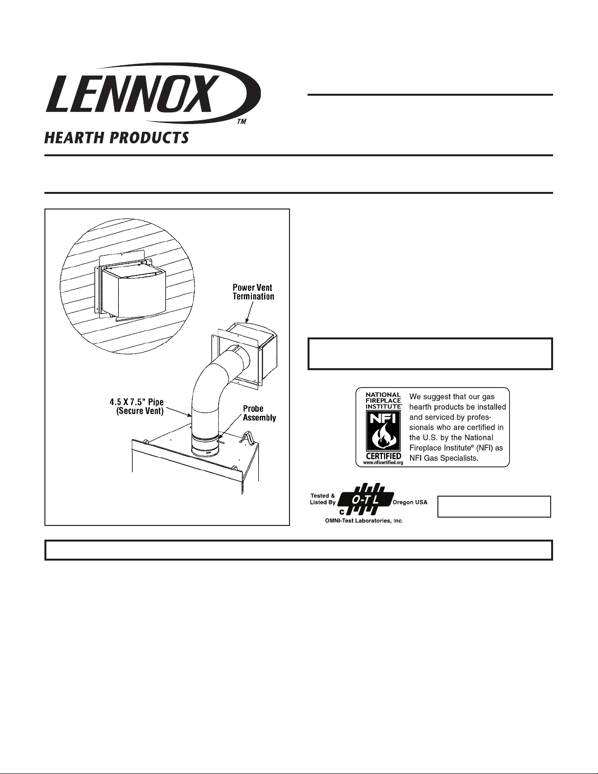
Figure 1 - Power Vent Assembly
OTL Report No. 116-F-39C-5
For Use With Lennox ELDV Fireplaces (Electronic Models) Catalog Numbers: H3950 (35”), H3953” (40”) and H3956 (45”)
NOTE: DIAGRAMS & ILLUSTRATIONS NOT TO SCALE.
1
Page 2
INSTALLATION INSTRUCTIONS
Locate the fireplace as per the instructions supplied under the fireplace. Make the following modifications to add the components used with the
Power Vent Kits. This kit can only be used in conjunction with “Direct Vent” series electronic versions of Lennox Fireplaces. This installation must
conform with local codes or, in the absence of local codes, with the Natural Fuel Gas Code, ANSI Z223.1/NFPA 54, or the Natural Gas and Propane
Installation Code, CSA B149.1.
CAUTION: The LPVK-110 Power Vent Kit cannot be used with Millivolt appliances. Use the LPVK-110 only with the Electronically controlled fireplaces listed for its use as shown in this document.
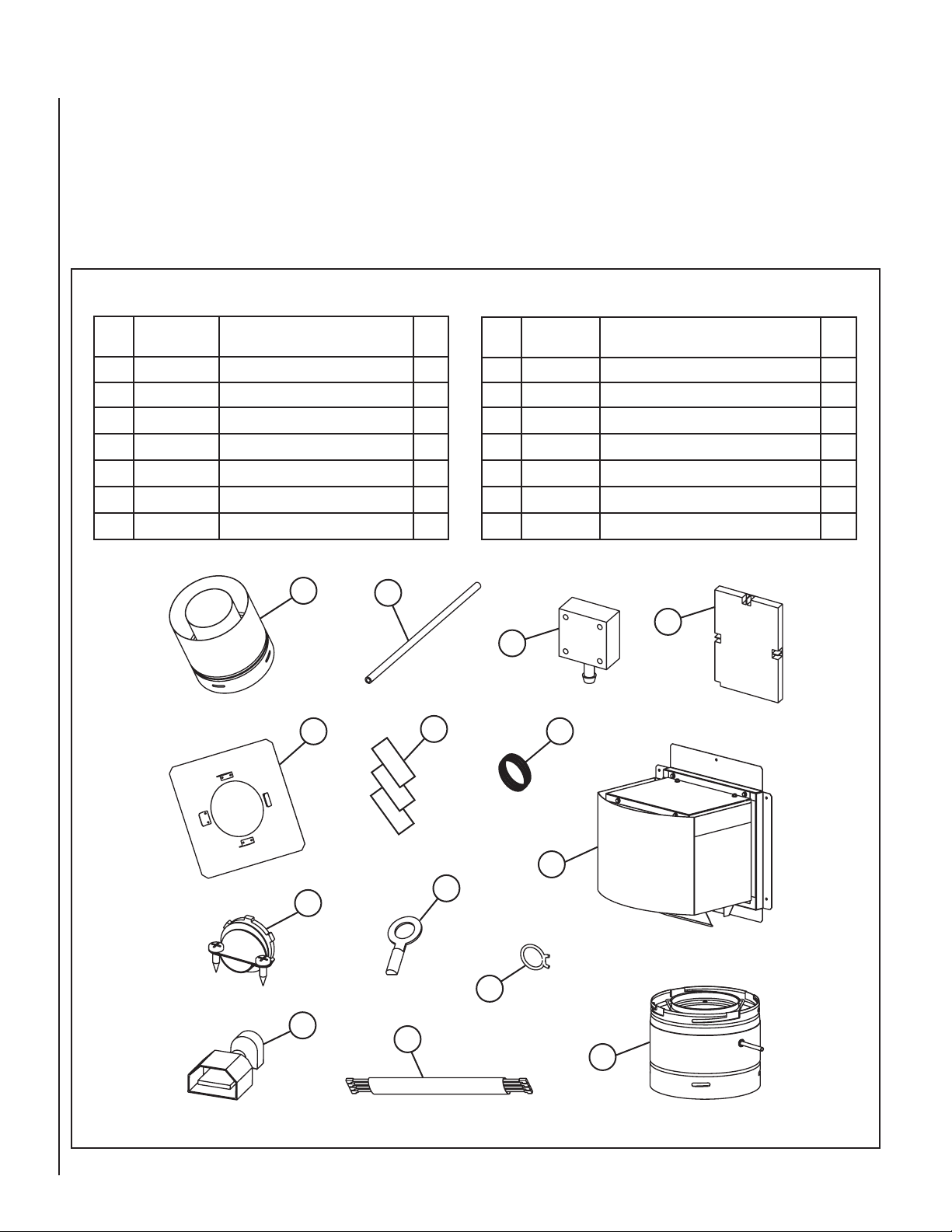
POWER VENT KIT CONTENTS
Item
No.
1 601970-01
Part
Number
Description Qty.
Vacuum Hose 1
2 102019-01 Wiring Harness 1
3 102005-01 Pressure Switch 1
4 102009-01 Control Module 1
5 102010-01 Strain Relief - 3/8” 2
6 102021-01 Ring Terminal - #10 2
7 H7384 Insulated 1/4” Male Terminal 4
12
1
13
14
Item
No.
8 102022-01
Part
Number
Description Qty.
Hose Clamp - 11/32” 2
9 P-8-7102 Snap Bushing 2
10 601957-01 Power Vent Termination 1
11 601978-01 Probe Assembly 1
12 74L61 SV Termination Adapter (SV4.5RCH) 1
13 H2246 Firestop Assembly (Horizontal) 1
14 67L6501 Velcro Strips (2” Lengths) 3
4
3
9
Power Vent Kit Components
2
10
6
5
8
7
2
11
NOTE: DIAGRAMS & ILLUSTRATIONS NOT TO SCALE.
Page 3
PREPARE THE FIREPLACE FOR POWER-VENTING
Exterior
Wall
3 Feet
Below Bottom
Of Fireplace
Maximum
SV4.5E90
Elbow
Horizontal / Inclined Run
Power Vent
Termination
Support
Brackets
Building
Support
Framing
Exterior
Wall
Power Vent
Termination
Power Vent
Termination
Fireplace
Firestop/Spacer
Ceiling
Maximum
Vertical Rise
66 Feet
Probe Adapter
(Required)
Probe Adapter
(Required)
Minimum
Vent Run 8’
Horizontal
Probe Adapter
(Required)
SV4.5E90
Elbow
SV4.5L6/12/24/36/48
Vent Sections
SV4.5L6/12/24/36/48
Vent Sections
Firestop/Spacer
Maximum Horizontal
Venting 110’ Max.
Up To 6 Elbows
Fireplace
Floor
5/8” Restrictor
1” Restrictor
Rear Log Bracket
Modify fireplace for acceptance of the power vent kit. Refer to Table 1
and install the appropriate adapter kit. Follow the instructions provided
with the kit to successfully prepare the fireplace for use with power
venting. If no kit is listed, the fireplace will not require modification.
Refer to the fireplace installation instructions for details and information
detailing its compatibility with power venting. If its is not compatible, do
not power-vent the fireplace.
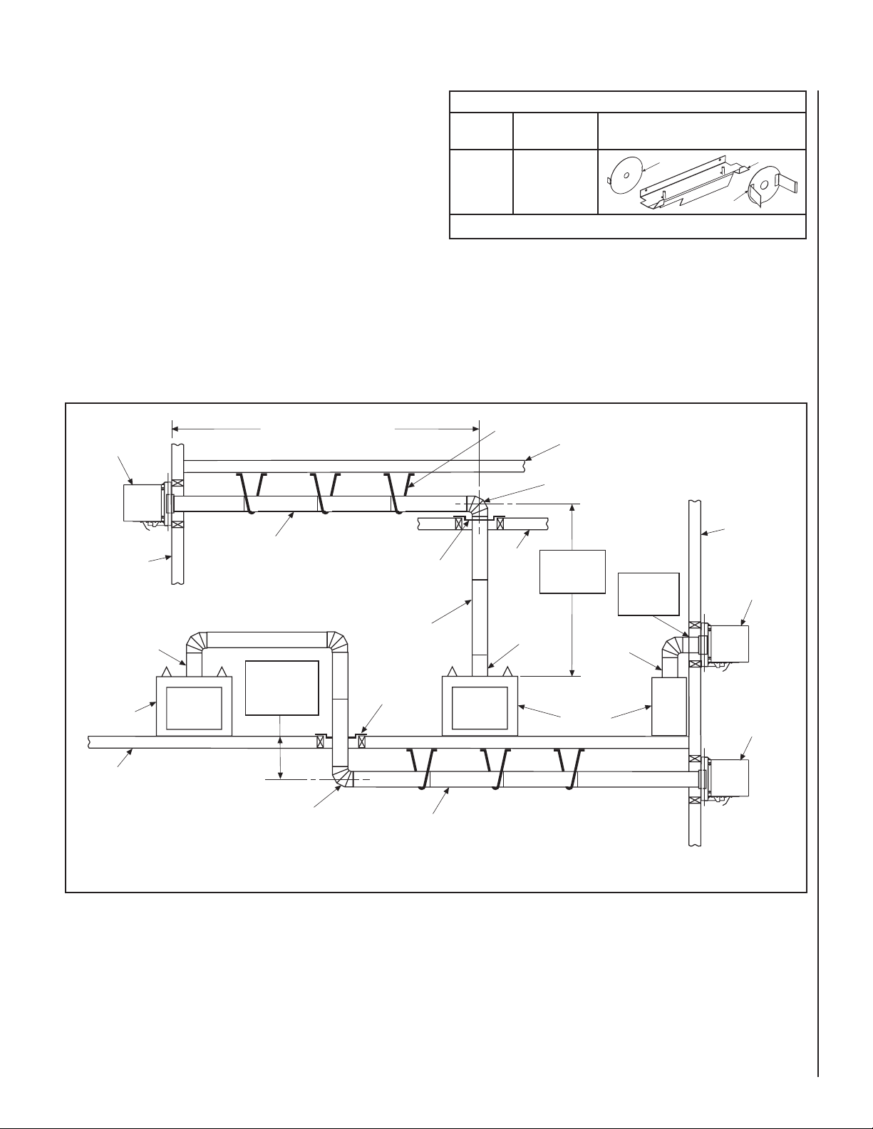
VENTING THE FIREPLACE
Venting Configurations
Maximum vent is 110 feet, plus six 90-degree elbows or twelve 45degree elbows. Minimum horizontal vent length is 8 feet, maximum
vertical rise above the fireplace is 66 feet. The vent can be installed
with any combination or rise and run between appliance and termination, including up to 3 feet below the unit (see Figure 2 ). Ensure
vent pipe is properly supported.
Fireplace
Model
ELDV
Table 1
FIREPLACE ADAPTER KITS (For LPVK-110)
Kit Catalog
Number
Kit Contents
H7407
(ELDV-PVAK)
Figure 2 Typical Power Vent Routing
NOTE: DIAGRAMS & ILLUSTRATIONS NOT TO SCALE.
3
Page 4
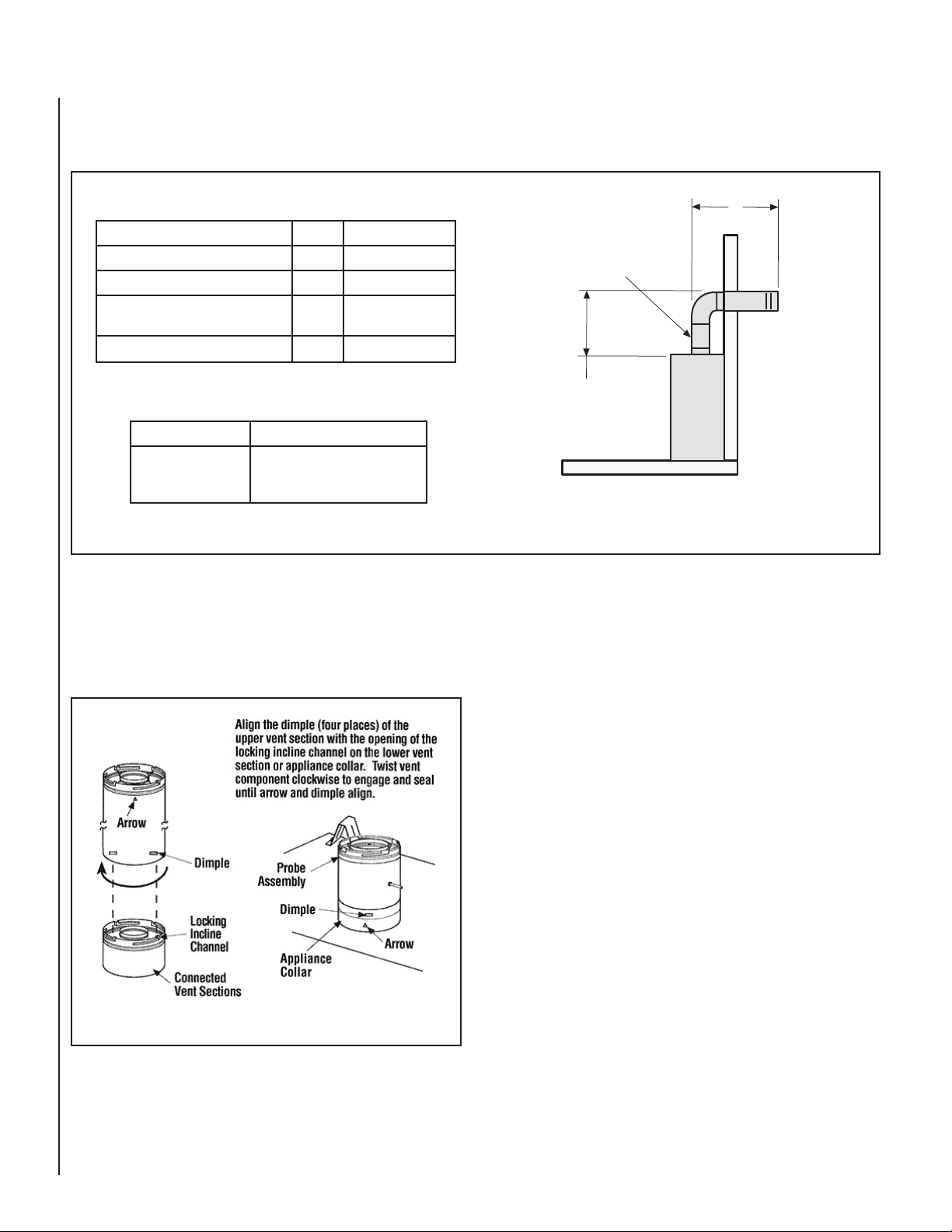
VENT CLEARANCES
A
(See Chart)
B
Probe Assembly
(Required)
Refer to the charts and illustration in Figure 3 for vent clearances for the LPVK-110 Power Vent Kit.
POWER VENT VENTING CHART
Maximmum Number Of Elbows - 6
Maximum Feet Of Run
Minimum Horizontal Run B 8 feet
Minimum Vertical Run A
Maximum Vertical Rise A
MINIMUM CLEARANCES TO COMBUSTIBLES
Vertical Vent Pipe 1.0 in. (25.4 mm)
Horizontal Vent
Pipe
Figure 3
A + B 110 feet
Probe Assembly
And Elbows
66 feet
Top - 3.0 in. (76.2 mm)
Sides - 1.0 in. (25.4 mm)
Bottom - 1.0 in. (25.4 mm)
All other clearances are as per the appliance Installation Instructions
INSTALL PROBE ASSEMBLY ON THE FIREPLACE
• Attach the probe assembly to appliance. The probe assembly (# 11
from Parts List) is of the same design as the unitized concentric pipe
components of the SV4.5 Secure-Vent System, featuring positive twist
lock connections (see Figure 4 ).
Figure 4
CAUTION: The probe assembly must be installed directly to the appliance collar. Install the probe assembly first before connecting any
other vent components to the fireplace.
All of the appliances that can be installed with this power vent kit, are
fitted with collars having locking inclined channels. The dimpled end of
the probe assembly fits over the appliance collar to create the positive
twist lock connection.
To attach the probe assembly to the appliance collar, align the dimpled
end over the collar, adjusting the radial alignment until the four locking
dimples are aligned with the inlet of the four inclined channels on the
collar (refer to Figure 4 ). Push the probe assembly against the collar
until it fully engages, then twist the probe assembly clockwise, running
the dimples down and along the incline channels until they seat at the
end of the channels. The unitized design of the probe assembly components will engage and seal both the inner and outer pipe without the
need for sealant or screws.
• Attach vent components to the probe assembly. Other vent sections
may be added to the previously installed probe assembly in accordance
with the requirements of the fireplace installation instructions and the
vent charts provided in the instructions.
4
NOTE: DIAGRAMS & ILLUSTRATIONS NOT TO SCALE.
Page 5
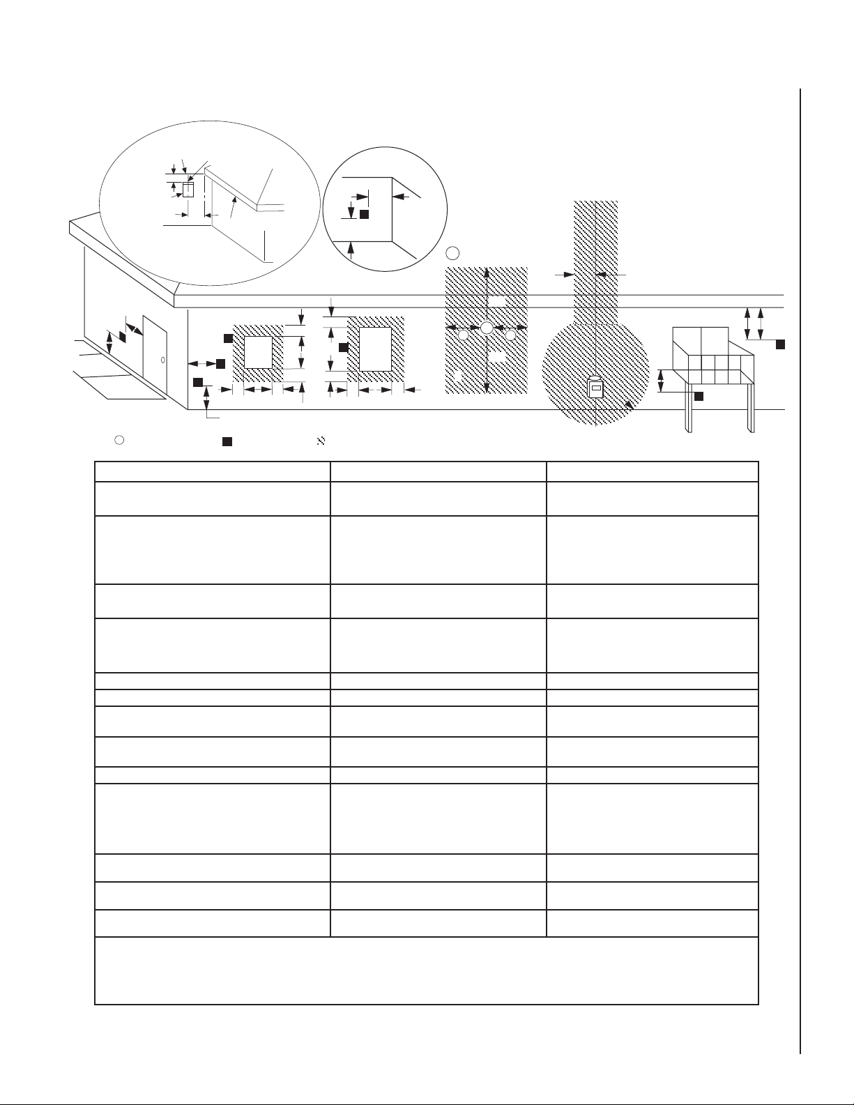
EXTERIOR HORIZONTAL VENT TERMINATION CLEARANCE REQUIREMENTS
F
C
Fixed
Closed
Window
Operable
Window
B
B
A
B
H
M
I
= Vent Terminal = Area where Terminal is not Permitted
= Air Supply Inlet
X
D
3 ft.
3 ft.
A
A
A
= 9” in U.S.
= 12” in Canada
V
L
B
J
X
E
V
A
G
Inside
Corner Detail
B
C
C
C
*18”
Ventilated Soffit
Horizontal
Termination
Detail D
Exterior Wall
Center Line
of Termination
18”
Inside Corner
* See Item D in the Text Below.
V
V
V
V
V
V
V
*noitallatsnInaidanaC **noitallatsnISU
,hcrop,adnarev,edargevobaecnaraelC=A
.ynoclabro,kced .ynoclabro,kced
.ynoclabro,kced
.ynoclabro,kced .ynoclabro,kced
*)mc03(sehcni21 **)mc03(sehcni21
ebyamtahtroodrowodniwotecnaraelC=B
.denepo .denepo
.denepo
.denepo .denepo
secnailpparof)mc51(ni6
)mc03(ni21,)Wk3(hutB000,01< )mc03(ni21,)Wk3(hutB000,01<
)mc03(ni21,)Wk3(hutB000,01<
)mc03(ni21,)Wk3(hutB000,01< )mc03(ni21,)Wk3(hutB000,01<
dna)Wk3(hutB000,01>secnailpparof dna)Wk3(hutB000,01>secnailpparof
dna)Wk3(hutB000,01>secnailpparof
dna)Wk3(hutB000,01>secnailpparof dna)Wk3(hutB000,01>secnailpparof
)mc19(sehcni63,)Wk03(hutB000,001< )mc19(sehcni63,)Wk03(hutB000,001<
)mc19(sehcni63,)Wk03(hutB000,001<
)mc19(sehcni63,)Wk03(hutB000,001< )mc19(sehcni63,)Wk03(hutB000,001<
*)Wk03(hutB000,001>secnailpparof *)Wk03(hutB000,001>secnailpparof
*)Wk03(hutB000,001>secnailpparof
*)Wk03(hutB000,001>secnailpparof *)Wk03(hutB000,001>secnailpparof
secnailpparof)mc51(ni6
)mc32(ni9,)Wk3(hutB000,01< )mc32(ni9,)Wk3(hutB000,01<
)mc32(ni9,)Wk3(hutB000,01<
)mc32(ni9,)Wk3(hutB000,01< )mc32(ni9,)Wk3(hutB000,01<
dna)Wk3(hutB000,01>secnailpparof dna)Wk3(hutB000,01>secnailpparof
dna)Wk3(hutB000,01>secnailpparof
dna)Wk3(hutB000,01>secnailpparof dna)Wk3(hutB000,01>secnailpparof
)mc03(sehcni21,)Wk51(hutB000,05< )mc03(sehcni21,)Wk51(hutB000,05<
)mc03(sehcni21,)Wk51(hutB000,05<
)mc03(sehcni21,)Wk51(hutB000,05< )mc03(sehcni21,)Wk51(hutB000,05<
**)Wk51(hutB000,05>secnailpparof **)Wk51(hutB000,05>secnailpparof
**)Wk51(hutB000,05>secnailpparof
**)Wk51(hutB000,05>secnailpparof **)Wk51(hutB000,05>secnailpparof
wodniwdesolcyltnenamrepotecnaraelC=C tneverpotdednemmocer)mm503("21
noitasnednocwodniw noitasnednocwodniw
noitasnednocwodniw
noitasnednocwodniw noitasnednocwodniw
tneverpotdednemmocer)mm922("9
noitasnednocwodniw noitasnednocwodniw
noitasnednocwodniw
noitasnednocwodniw noitasnednocwodniw
tiffosdetalitnevotecnaraelclacitreV=D
latnozirohanihtiwlanimretehtevobadetacol latnozirohanihtiwlanimretehtevobadetacol
latnozirohanihtiwlanimretehtevobadetacol
latnozirohanihtiwlanimretehtevobadetacol latnozirohanihtiwlanimretehtevobadetacol
retnecehtmorf)mm854(sehcni81foecnatsid retnecehtmorf)mm854(sehcni81foecnatsid
retnecehtmorf)mm854(sehcni81foecnatsid
retnecehtmorf)mm854(sehcni81foecnatsid retnecehtmorf)mm854(sehcni81foecnatsid
lanimretehtfoenil lanimretehtfoenil
lanimretehtfoenil
lanimretehtfoenil lanimretehtfoenil
)mm854("81 )mm854("81
tiffosdetalitnevnuotecnaraelC=E )mm503("21 )mm503("21
renrocedistuootecnaraelC=F muminim)mc7.21("5 muminim)mc7.21("5
renrocedisniotecnaraelC=G
"42 "42
enilretnecfoedisnihcaeotecnaraelC=H
ylbmessarotaluger/retemevobadednetxe ylbmessarotaluger/retemevobadednetxe
ylbmessarotaluger/retemevobadednetxe
ylbmessarotaluger/retemevobadednetxe ylbmessarotaluger/retemevobadednetxe
teef51fothgiehanihtiw)mc19(teef3
*ylbmessarotaluger/retemehtevoba *ylbmessarotaluger/retemehtevoba
*ylbmessarotaluger/retemehtevoba
*ylbmessarotaluger/retemehtevoba *ylbmessarotaluger/retemehtevoba
teef51fothgiehanihtiw)mc19(teef3
**ylbmessarotaluger/retemehtevoba **ylbmessarotaluger/retemehtevoba
**ylbmessarotaluger/retemehtevoba
**ylbmessarotaluger/retemehtevoba **ylbmessarotaluger/retemehtevoba
teltuotnevrotalugerecivresotecnaraelC=I *)mc19(teef3 **)mc19(teef3
telniylppusrialacinahcemnonotecnaraelC=J
ynaottelnirianoitsubmocehtrognidliubot ynaottelnirianoitsubmocehtrognidliubot
ynaottelnirianoitsubmocehtrognidliubot
ynaottelnirianoitsubmocehtrognidliubot ynaottelnirianoitsubmocehtrognidliubot
ecnailpparehto ecnailpparehto
ecnailpparehto
ecnailpparehto ecnailpparehto
secnailpparof)mc51(ni6
)mc03(ni21,)Wk3(hutB000,01< )mc03(ni21,)Wk3(hutB000,01<
)mc03(ni21,)Wk3(hutB000,01<
)mc03(ni21,)Wk3(hutB000,01< )mc03(ni21,)Wk3(hutB000,01<
dna)Wk3(hutB000,01>secnailpparof dna)Wk3(hutB000,01>secnailpparof
dna)Wk3(hutB000,01>secnailpparof
dna)Wk3(hutB000,01>secnailpparof dna)Wk3(hutB000,01>secnailpparof
)mc19(sehcni63,)Wk03(hutB000,001< )mc19(sehcni63,)Wk03(hutB000,001<
)mc19(sehcni63,)Wk03(hutB000,001<
)mc19(sehcni63,)Wk03(hutB000,001< )mc19(sehcni63,)Wk03(hutB000,001<
*)Wk03(hutB000,001>secnailpparof *)Wk03(hutB000,001>secnailpparof
*)Wk03(hutB000,001>secnailpparof
*)Wk03(hutB000,001>secnailpparof *)Wk03(hutB000,001>secnailpparof
secnailpparof)mc51(ni6
)mc32(ni9,)Wk3(hutB000,01< )mc32(ni9,)Wk3(hutB000,01<
)mc32(ni9,)Wk3(hutB000,01<
)mc32(ni9,)Wk3(hutB000,01< )mc32(ni9,)Wk3(hutB000,01<
dna)Wk3(hutB000,01>secnailpparof dna)Wk3(hutB000,01>secnailpparof
dna)Wk3(hutB000,01>secnailpparof
dna)Wk3(hutB000,01>secnailpparof dna)Wk3(hutB000,01>secnailpparof
)mc03(sehcni21,)Wk51(hutB000,05< )mc03(sehcni21,)Wk51(hutB000,05<
)mc03(sehcni21,)Wk51(hutB000,05<
)mc03(sehcni21,)Wk51(hutB000,05< )mc03(sehcni21,)Wk51(hutB000,05<
**)Wk51(hutB000,05>secnailpparof **)Wk51(hutB000,05>secnailpparof
**)Wk51(hutB000,05>secnailpparof
**)Wk51(hutB000,05>secnailpparof **)Wk51(hutB000,05>secnailpparof
telniylppusrialacinahcemaotecnaraelC=K *)m38.1(teef6 )m3(teef01nihtiwfievoba)mc19(teef3
**yllatnoziroh **yllatnoziroh
**yllatnoziroh
**yllatnoziroh **yllatnoziroh
devaproklawedisdevapevobaecnaraelC=L
ytreporpcilbupnodetacolyawevid ytreporpcilbupnodetacolyawevid
ytreporpcilbupnodetacolyawevid
ytreporpcilbupnodetacolyawevid ytreporpcilbupnodetacolyawevid
‡)m31.2(teef7 ‡)m31.2(teef7
rokced,hcrop,adnarevrednuecnaraelC=M
ynoclab ynoclab
ynoclab
ynoclab ynoclab
‡*)mc03(sehcni21 ‡)mc03(sehcni21
.edoCnoitallatsnIenaporPdnAsaGlanoitaN1.941B-ASCtnerrucehthtiwecnadroccanI*
.sedoCsaGleuFlanoitaN45APFN/1.322ZSISNAtnerucehthtiwecnadroccanI** .sedoCsaGleuFlanoitaN45APFN/1.322ZSISNAtnerucehthtiwecnadroccanI**
.sedoCsaGleuFlanoitaN45APFN/1.322ZSISNAtnerucehthtiwecnadroccanI**
.sedoCsaGleuFlanoitaN45APFN/1.322ZSISNAtnerucehthtiwecnadroccanI** .sedoCsaGleuFlanoitaN45APFN/1.322ZSISNAtnerucehthtiwecnadroccanI**
sevresdnasgnillewdylimafelgnisowtneewtebdetacolsihcihwyawevirddevaproklawedisaevobayltceridetanimrettonllahstnevA‡ sevresdnasgnillewdylimafelgnisowtneewtebdetacolsihcihwyawevirddevaproklawedisaevobayltceridetanimrettonllahstnevA‡
sevresdnasgnillewdylimafelgnisowtneewtebdetacolsihcihwyawevirddevaproklawedisaevobayltceridetanimrettonllahstnevA‡
sevresdnasgnillewdylimafelgnisowtneewtebdetacolsihcihwyawevirddevaproklawedisaevobayltceridetanimrettonllahstnevA‡ sevresdnasgnillewdylimafelgnisowtneewtebdetacolsihcihwyawevirddevaproklawedisaevobayltceridetanimrettonllahstnevA‡
.sgnillewdhtob .sgnillewdhtob
.sgnillewdhtob
.sgnillewdhtob .sgnillewdhtob
:roolfehthtaenebsedis2muminimanonepoyllufsiynoclabrokced,hcrop,adnarevfidettimrepylnO‡* :roolfehthtaenebsedis2muminimanonepoyllufsiynoclabrokced,hcrop,adnarevfidettimrepylnO‡*
:roolfehthtaenebsedis2muminimanonepoyllufsiynoclabrokced,hcrop,adnarevfidettimrepylnO‡*
:roolfehthtaenebsedis2muminimanonepoyllufsiynoclabrokced,hcrop,adnarevfidettimrepylnO‡* :roolfehthtaenebsedis2muminimanonepoyllufsiynoclabrokced,hcrop,adnarevfidettimrepylnO‡*
Figure 5
NOTE: DIAGRAMS & ILLUSTRATIONS NOT TO SCALE.
5
Page 6

BEGIN VENTING
PROBE (11)
HOSE CLAMP (8)
VACUUM HOSE (1)
• Install the strain relief (#5) on the termination as shown in Figure 9.
Horizontal (Outside Wall) Termination System
NOTE: The LPVK-110 Power Vent system can only be terminated
horizontally.
Various horizontal venting configurations are possible for use with
these power vent kit. Secure Vent pipe are used in these applications.
Refer to Figures 2, 3 and Tables in Figure 3 which summarizes each
system’s minimum and maximum vertical and horizontal length values
that can be used to design and install the vent components in a variety
of applications.
Horizontal vent systems terminate through an outside wall. Building
Codes limit or prohibit terminating in specific areas. Refer to local codes
and Figure 5 for location guidelines.
• Plan and execute the vent run -
Analyze the vent routing and determine the types and quantities of sections and elbows required. Vent sections are available in net lengths of
4-1/2” (114 mm), 10-1/2” (267 mm), 22-1/2” (572 mm), 34-1/2” (876
mm) and 46-1/2” (1181 mm). Plan the vent lengths so that a joint
does not occur at the intersection of ceiling or roof joists. Elbows are
available in 90° and 45° configurations. Make allowances for elbows
as indicated in the appliance installation instructions.
Maintain a minimum 1” (25 mm) clearance to combustibles on the
vertical sections. Clearances for the horizontal runs are; 3” (76 mm)
on top, 1” (25 mm) on sides, and 1” (25 mm) at the bottom.
• Refer to Figure 10 to connect the three wires of the Romex cable to
the termination. Ensure the ground ring terminal is grounded beneath
a structural screw as shown. Attach the junction box cover (#22) to the
termination with the three screws previously removed.
• Route 14 gauge AWG grounded Romex wiring (not provided). Ensure
the wiring is safety plated to prevent damage by framing nails and finish drywall screws. Route the wire into the lower control compartment
and cut to length before installing the terminals. Install provided wiring
hardware (# 6,7) on the ends of the Romex wire.
Fireplace (J-Box) Wiring
(Refer to appliance Installation
Instructions For Directions)
Strain Relief (5)
Snap
Bushing (9)
Install Vacuum Hose
• Refer to Figure 6 and remove the knockouts located where the strain
relief (#5) and snap bushing (#9) are to be installed, at the lower right
hand side.
• Install the snap bushing (#9) in the hole provided on the fireplace for
the vacuum hose (refer to Figure 6 ).
• Route the vacuum hose (#1), taking caution to not kink and/or damage
the hose (refer to Figure 6 ). Route the hose from the probe assembly
(#11) location to the appliance control compartment, through the snap
bushing previously installed. Ensure enough material is available at
either end to allow hook up. Ensure the hose is safety plated throughout
its run to prevent damage by framing nails and finish drywall screws.
Secure the vacuum hose (#1) to the probe (#11) with the hose clamp
(#8). Refer to Figure 7.
Route Wiring
NOTE: Electrical wiring must be performed by a qualified electrician.
• Install the strain relief (#5) in the hole provided on the fireplace for
the electrical wiring (refer to Figure 6 ).
• Remove the junction box cover (#22) from the termination by removing three screws (refer to Figure 8 ).
Figure 6
Figure 7
14 Gauge
Grounded Romex
Vacuum Hose (1)
6
NOTE: DIAGRAMS & ILLUSTRATIONS NOT TO SCALE.
Page 7

BLACK & WHITE
GROUND WIRE
ROMEX
6
7
(BOTTOM OF TERMINATION)
Junction Box Cover (22)
• Refer to Figure 10 and install the electrical hardware on the ends of
the Romex wiring. Male terminals (#7) on the Black and White wires,
and ring terminals (#6) on the ground wire.
Figure 10
Termination Wiring
Figure 8
(BACK OF TERMINATION)
Strain Relief (5)
Romex Wire
Figure 11
Strain Relief (5)
Ground Wire Lug (6)Male Terminals (7)
Figure 9
NOTE: DIAGRAMS & ILLUSTRATIONS NOT TO SCALE.
7
Page 8

Installing Power Vent Termination
Siding
Stucco
1-1 /4" Maximu m Recess of
the Squa re Term ina tion into
Exteri or Finishing Material
Exterior Surface of
Framing
5 in. to 9-1/4 in.
(127 to 235 mm)**
Exterior Surface of Siding
Interior Surface of
Finished Wall
Maximum wall thickness
10 in.(254 mm)**
Power Vent
Termination
Maximum Extent of Vent Run
Sections Relative to Exterior
Surface of Framing
Last Vent Section.
Use Telescopic Vent
Section (SV4.5LA),
If Necessary
Adapter
SV4.5RCH
Venting Connection and Exterior Wall Recessing
of the Power Vent Horizontal Termination
*Use silicone caulking to
seal the top and sides of
the termination, up to the
underlayment, stucco, or
masonry wall surface.
**For thicknesses greater
than 10”, see Appliance
Installation Instructions.
Power Vent
Termination
*Caulk
*Caulk
Firestop/Spacer (SV4.5HF) shown
on the exterior side of the wall. It
may also be installed on the
interior side.
Power Vent
Termination
7"
(178)
5-1/8"
(130 mm)
12-1/8"
(308 mm)
Note: Centerline of Vent Piping is
NOT the Same as the Centerline of
the Frame Opening.
6 to 48 inch Vent Section,
Telescopic vent section,
Elbow or Appliance Collar
See Appliance Installation
Instructions for Min. Distance
to Base of Appliance.
Base of Appliance
3"
(76 mm)
1"
(25.4 mm)
Adapter
SV4.5RCH
10-1/2"
(267 mm)
• Assemble vent run to exterior wall - If not
previously measured, locate the center of the
vent on the exterior wall. Prepare an opening
as described in the appliance installation
instructions. Assemble the vent system to a
point where the terminus of the last section
is within 8 inches of the outside wall surface
where the power vent is to be mounted (refer
to Figure 12 ).
If the terminus of the last section is not within
this distance, use the telescopic vent section
SV4.5LA, as the last vent section. For wall thicknesses greater than that shown in Figure 12,
refer to the appliance Installation Instructions
for the additional venting components needed
(in addition to the termination and adapter) for
a particular range of wall thicknesses.
• Attach termination adapter - Attach the
adapter (adapter - SV4.5RCH - provided with the
power vent kit - #12) to the vent section telescoping vent section, or elbow or appliance collar, as
shown in Figure 13 in the same manner as any
SV4.5 vent component.
Figure 12
• Install Firestop/Spacer at exterior wall -
Install SV4.5HF Firestop/Spacer (#13), provided
with the power vent kit, over the opening at the
exterior side of the framing, long side up, with
the 3 inch spacer clearance at the top as shown
in Figure 13, and nail into place.
(The Firestop/Spacer may also be installed over
the opening at the interior side of the framing).
• Install the Power Vent termination (#10)
- For the last step, from outside the exterior
wall, slide the collars of the termination onto
the adapter (the outer inside the outer and the
inner outside the inner) until the termination
seats against the exterior wall surface to which
it will be attached. Orient the housing of the
termination with the arrow pointed upwards.
Secure the termination to the exterior wall.
The termination must not be recessed into the
exterior wall or siding by more that the 1-1/4”
(32 mm) as shown in Figure 12.
The Power Vent termination has been designed to perform in a wide range of weather conditions. Our terminations meet or exceed
industry standards.
When selecting the location of your termination, do not place the termination where water from eaves and adjoining roof lines may
create a heavy flow of cascading water onto the terminations. If the termination must be placed where the possibility of cascading
water exists, it is the responsibility of the builder to direct the water away from the termination cap by using gutters or other means.
Take care to carefully follow the Installation Instructions for the termination, including the use of silicone caulking where required.
8
Figure 13 Installing Power Vent Horizontal Termination
NOTE: DIAGRAMS & ILLUSTRATIONS NOT TO SCALE.
Page 9

Connecting The Power Vent To The Fireplace Control System
• Disconnect and remove the battery pack. See Figures 15 and 16.
Remove any control compartment cover or access plates and set aside.
Ensure power is off to the fireplace.
Connecting To Battery Backed-up Dexen Systems
Refer to the general components layout shown in Figure 14.
Control Module System Power Cord
On/Off Switch Pressure Switch (3) Power Outlets Control Module Power Cord
• Disconnect system power transformer (3V) from power outlet. Refer
to Figure 14.
• Disconnect 2 brown wires from the On/Off switch.
• Reconnect 2 brown wires to the control module (#4). See Figure 17.
System Power Transformer
4 Wire Harness (2)Vacuum Hose (1)
Figure 14 General System Layout (Firebox Floor Removed For Clarity)
Bundle Disconnected Wire (Do Not Re-use)
Battery Pack (Remove) Disconnect Here
Figure 15
Figure 16
Control Module (4)
Disconnected Battery Pack
NOTE: DIAGRAMS & ILLUSTRATIONS NOT TO SCALE.
9
Page 10

• Position the pressure switch (#3) on the fireplace cabinet bottom.
Refer to Figure 14 and Figure 18. Secure in position using Velcro strips
(#4) provided. Install vacuum hose to the pressure switch. Secure with
hose clamp (#8).
Two Brown Wires
From On/Off Switch
Wires To DV
Termnation
Termination
Ground
• Connect control module (#4) (To Power Vent) to the power wire
for the power vent termination. Remove the paint plug from the
fireplace corner post to expose the bare metal at the grounding point
and connect the PV (Romex ground wire) ground with the Control
Module ground wire to the grounding point with the screw provided.
See Figure 19.
• Connect the control module (#4) power plug to the power socket.
(See Figure 19 ).
• Refer to Figure 14 and ensure all components are properly placed.
Ensure the ON/Off switch is secure and the pressure switch is in place.
Ensure the fireplace blower (if used) is installed and connected to
the power socket.
• Place the control module (#4) into position. Secure in position using Velcro strips provided. See Figure 20 and refer to Figure 14.
Control Module Power Plug
Control Module Ground
Figure 17
• Connect four-wire harness (#2) to the control module (#4) (Figure
17 ) at T-STAT (Red) and V-SWITCH (Black). Connect the other end
of the four-wire harness to the unit/wall On/Off switch and pressure
switch (#3) (Figure 18 ), black to the pressure switch, red to the
On/Off switch.
Control Module (4)
System Power Cord
Two 1/4” Wires
(Red)
Two 3/16” Wires
(Black)
Figure 19
Power Vent
Ground
Ground
Point
Control Module Ground
Control Module (4)
Power Supply
Transformer
On/Off Switch
(Wall)
Four-Wire
Harness (2)
Pressure
Switch (3)
Figure 18
• Connect the transformer (3V) to the control module system power.
(Refer to Figure 18 ).
10
NOTE: DIAGRAMS & ILLUSTRATIONS NOT TO SCALE.
Figure 20
Page 11

OPTIONAL
BLOWER SWITCH
JUNCTION BOX
EXHAUST
GR
120 VAC
BK
W
W
BK
R
OPTIONAL BLOWER
14-AWG
BLACK
BLACK
RED
RED
VACUUM
SWITCH
EXHAUST BOWER
CONTROL MODULE
THERMOSTAT OR
WALL SWITCH
BROWN
BROWN
TRANSFORMER 3V
IGNITOR MODULE 3V
BLACK (IGNITOR)
BLACK (SENSOR)
SPARK TO PILOT IGNITOR
ORANGE (THTP)
BLACK (TP)
GREEN (TH)
GAS VALVE
PILOT
IN
IN
POWER VENT WIRING DIAGRAM
NOTE: DIAGRAMS & ILLUSTRATIONS NOT TO SCALE.
11
Page 12

POWER VENT OPERATING INSTRUCTIONS
16.17
(411 mm)
15.92
(404 mm)
10.00
(254 mm)
11.19
(284 mm)
13.50
(343 mm)
Top View
Front View
Power Vent Control Sequences
Turn On
1. Turn On The Thermostat Or On/Off Switch.
2. Blower Should Start Immediately.
3. Ignitor Starts Sparking And Pilot Will Light.
4. Burner Should Light After A Few Seconds.
5. Fireplace Should Run Continuously Until Thermostat Or On/Off Switch Is Turned Off.
Turn Off
1. Turn Off The Thermostat Or On/Off Switch.
2. Burner And Pilot Should Be Off Immediately.
3. Blower Will Continue To Run For About 90 Seconds And Then The Blower Will Stop.
Note: Dimensions Are In Inches (mm)
POWER VENT SPECIFICATIONS
12
NOTE: DIAGRAMS & ILLUSTRATIONS NOT TO SCALE.
Page 13

TROUBLESHOOTING THE POWER VENT SYSTEM
Important: Service must be performed by a qualified installer, service agency or your gas supplier.
BEFORE COMMENCING TO TROUBLESHOOT THE UNIT:
1. Check if there is power to the unit (fireplace).
2. Check if there is gas to the unit (fireplace).
3. The igniter module in the fireplace is equipped with a lockout device, which will put the unit into a lockout condition. Follow the steps in the
chart below to reset the control: Turn the On/Off switch to the Off position, or turn the thermostat to the Off position.
4. If this is the first time that the unit has been fired, check the wiring of the unit against the wiring diagram before commencing troubleshooting.
START
Power Vent Motor
Is Working?
Yes
On/Off Switch Or Wall Thermostat “On”?
No
Is There 120V Power To The Fireplace?
Are All Wiring Connections Tight?
(Turn Off Power Before Checking)
Is There 120V Power
Yes
To The Motor?
No
Yes
Replace Blower
Replace Control Module
Does The Pilot
Spark?
Yes
Pilot Burner
Lights?
Yes
Does Spark
Stop When Pilot
Lights?
Yes
Does Main Burner
Light?
Yes
No No
Yes
Is The Lead To The
Spark Electrode
Attached Or Arcing
To Ground? Is The
Electrode Cracked?
No
No
No
No
Is Pilot Gas Line
Blocked? Is Pilot
Orifice Blocked?
No
Does Pilot Flame
Cover The Flame
Rod?
No
Check Pilot For Obstruction.
Check Gas Pressure.
Adjust Pilot Flame.
Is There 1V Power
At Terminal 1 (MV)
During Spark Cycle?
No
Yes
Is The Pressure
Switch Closed?
Yes
Replace Control
Module
Replace Ignition Module
Yes
Yes
Replace Pilot
Replace Ignition Module
Is The Flame Rod Corroded?
Is The Pilot Hood Corroded?
Is Flame Rod Insulator Cracked?
Is Wire To Flame Rod Damaged?
Are Wires To Valve
Loose Or Corroded?
Replace Ignition Module
Is There Blockage In The Vent?
Is There Water/Dirt In The Hose From
The Blower To The Pressure Switch?
Are the Hose Connections Loose?
Is The Hose Cracked?
WARNING: Never Jump The Pressure
Switch Out Of This System. Property
Damage, Injury Or Death May Result.
No
Replace Ignition Module
No
Is There Manifold Pressure?
No
Replace Gas Valve
No
Yes
Replace Pressure
Switch
Check Position Of
Pilot. Is Orifice
Blocked?
System Runs
Continuously
Until Switched
Off?
No
Is The Correct Size Of Orifice Restrictor Insalled In The Power Vent?
Does The Pilot Flame Cover The Flame Rod?
Is The Sensor Wire In Good Condition?
Is There Continuity To Ground From The Piloy Burner?
Yes
Does Pressure Switch Open During Operation?
No
Replace Ignition Module
NOTE: DIAGRAMS & ILLUSTRATIONS NOT TO SCALE.
Replace Control Module
Yes
Replace Pressure Switch
No
Is Vent Partially Blocked?
Is There Water/Dirt In Hose To Pressure Switch?
Are Hose Connections Loose?
Is The Hose Cracked?
No
Does System Run
Continue?
No
Replace Ignition
Modiule
13
Page 14

POWER VENT REPLACEMENT PARTS
25
19
20
18
17
16
15
9
4
26
23
24
22
1
5
21
8
6
2
7
3
Item
Part Number Description Qty.
1 H7383
2 H7369
3 H7366
4 H7367
5 H7368
6 H7370
7 H7384
8 H7371
9 P-8-7102
15 H7372
Vacuum Hose 1
Wire Harness
Pressure Switch
Control Module
Strain Relief - 3/8”
Ring Terminal - #10
Insulated 1/4” Male Terminal
Hose Clamp - 11/32”
Snap Bushing
Base Assembly (Power Vent)
Item Part Number
16 H7378
1
1
1
2
2
4
2
1
1
17 H7382
18 H7365
19 H7375
20 H7373
21 H7374
22 H7377
23 H7379
24 H7380
25 H7376
26 H7381
Kicker Assembly
Blower Gasket
Blower Assembly
Wrapper - Top
Wrapper
Wrapper - Bottom
J-Box
Diverter - Front
Diverter - Back
Wrapper Cover
Wire Mesh
Description
Qty.
1
1
1
1
1
1
1
1
1
1
1
14
NOTE: DIAGRAMS & ILLUSTRATIONS NOT TO SCALE.
Page 15

LISTED VENT COMPONENTS
The Power Vent Kit (LPVK-110) is designed and listed for use with Security Chimneys® SV4.5 Secure-Vent™ direct-vent systems. The following
list details the SV4.5 components are available for use in developing vent runs for the power vent system.
SECURE VENT COMPONENTS
Catalog Number
Model Number Description
77L70 SV4.5L6 6” Pipe Length
77L71 SV4.5L12 12” Pipe Length
77L72 SV4.5L24 24” Pipe Length
77L73 SV4.5L36 36” Pipe Length
77L74 SV4.5L48 48” Pipe Length
77L75 SV4.5LA 6” Pipe, Adjustable
77L76 SV4.5E45 Swivel 45° Elbow
77L77 SV4.5E90 Swivel 90° Elbow
96K92 SV4.5SP Support Plate
96K93 SV4.5SU Universal Support
H5816 SV4.5TWSK10 Through Wall Shield Kit
H3907 SV4.5RSA Attic Insulation Shield
H2247 SV4.5VF Firestop, Vertical (10 Pack)
H2246 SV4.5HF Firestop, Horizontal (10 Pack)
NOTE: This list is not complete, but is representative of components
most frequently used. Refer to Lennox Hearth Products catalog sheets
and individual fireplace installation instructions for a complete listing of
SV4.5 vent components listed for use in venting of this product.
NOTE: DIAGRAMS & ILLUSTRATIONS NOT TO SCALE.
15
Page 16

The manufacturer reserves the right to make changes at any time, without notice, in design, materials, specifications, prices and also to discontinue colors, styles and products.
Consult your local distributor for fireplace code information.
Printed in U.S.A. © 2008 by LHP
P/N 506022-01 REV. A 10/2008
16
NOTE: DIAGRAMS & ILLUSTRATIONS NOT TO SCALE.
1110 West Taft Avenue
Orange, CA 92865
 Loading...