

Page 1

7.3
M3000 Installation Guide
Page 2

Lenel® OnGuard® 7.3 M3000 Installation Guide
This guide is item number 461022001, revision G, June 2016.
© 2016 United Technologies Corporation. All rights reserved.
Lenel®, OnGuard® and Prism® (Registered trademarks of UTC Fire & Security Americas Corporation, Inc.)
Lenel is a part of UTC Climate, Controls & Security, a unit of United Technologies Corporation.
All trademarks are the property of their respective owners.
Information in this document is subject to change without notice. No part of this document may be reproduced
or transmitted in any form or by any means, electronic or mechanical, for any purpose, without the express
written permission of UTC Fire & Security Americas Corporation, Inc.
Non-English versions of Lenel documents are offered as a service to our global audiences. We have attempted
to provide an accurate translation of the text, but the official text is the English text, and any differences in the
translation are not binding and have no legal effect.
The software described in this document is furnished under a license agreement and may only be used in
accordance with the terms of that agreement.
Crystal Reports for Windows is a trademark of Crystal Computer Services, Inc.
OnGuard includes ImageStream® Graphic Filters. © 2002 eBT International, Inc. (f/k/a Inso Corporation). All
rights reserved. ImageStream Graphic Filters and ImageStream are registered trademarks of eBT
International, Inc. (f/k/a Inso Corporation).
Integral and FlashPoint are trademarks of Integral Technologies, Inc.
Portions of this product were created using LEADTOOLS ©1991-2011, LEAD Technologies, Inc. ALL
RIGHTS RESERVED. Portions of this product are licensed under US patent 5,327,254 and foreign
counterparts.
Active Directory, Microsoft, SQL Server, Windows, and Windows Server are either registered trademarks or
trademarks of Microsoft Corporation in the United States and/or other countries.
Oracle is a registered trademark of Oracle and/or its affiliates. Other names may be trademarks of their
respective owners.
Other product names mentioned may be trademarks or registered trademarks of their respective companies
and are hereby acknowledged.
Warranty
UTC Fire & Security Americas Corporation, Inc. ("Lenel") warrants that the product is free from defects in
material and workmanship under normal use and service with proper maintenance for one year from the date
of factory shipment. Lenel assumes no responsibility for products damaged by improper handling, misuse,
neglect, improper installation, over-voltages, repair, alteration, or accident. This warranty is limited to the
repair or replacement of the defective unit. In no event shall Lenel be liable for loss of use or consequential
damages of any kind, however occasioned. There are no expressed warranties other than those set forth herein.
Warranty expressly excludes third party additions, deletions and/or upgrades to this product, including those
contained herein. Lenel does not make, nor intends, nor does it authorize any agent or representative to make
any other warranties or implied warranties, and expressly excludes and disclaims all implied warranties of
merchantability or fitness for a particular purpose.
Returned units are repaired or replaced from a stock of reconditioned units. All returns must be accompanied
by a return authorization number (RMA) obtained from the Lenel customer service department prior to
returning or exchanging any product. The RMA number must appear on the outside of the shipping box and
on the packing slip. Any items returned without an RMA number will not be accepted and will be returned at
the customer's expense. All returns must have transportation, insurance, and custom brokers' fees prepaid.
Page 3

Liability
It is expressly understood and agreed that the interface should only be used to control exits from areas where
an alternative method for exit is available. This product is not intended for, nor is rated for operation in lifecritical control applications. Lenel is not liable under any circumstances for loss or damage caused by or
partially caused by the misapplication or malfunction of the product. Lenel's liability does not extend beyond
the purchase price of the product.
Page 4

Page 5

Table of Contents
CHAPTER 1 Introduction . . . . . . . . . . . . . . . . . . . . . . . . . . . . . . . . . . . . . . . . . . . . .9
Specifications . . . . . . . . . . . . . . . . . . . . . . . . . . . . . . . . . . . . . . . . . . . . . . . . . . . . . . . . . . . . . . . . .10
CPU Specifications . . . . . . . . . . . . . . . . . . . . . . . . . . . . . . . . . . . . . . . . . . . . . . . . . . . . . . . . . . . . . . . . . 12
Minimum Supported Board Levels for the PXNplus CPU Board . . . . . . . . . . . . . . . . . . . . . . . . .12
CHAPTER 2 Installation, Planning, and Mounting . . . . . . . . . . . . . . . . . . . . . . . .15
Safety . . . . . . . . . . . . . . . . . . . . . . . . . . . . . . . . . . . . . . . . . . . . . . . . . . . . . . . . . . . . . . . . . . . . . . .16
Radio Interference . . . . . . . . . . . . . . . . . . . . . . . . . . . . . . . . . . . . . . . . . . . . . . . . . . . . . . . . . . . . . . . . . . 16
Electrostatic Discharge (ESD) Precaution . . . . . . . . . . . . . . . . . . . . . . . . . . . . . . . . . . . . . . . . . . . . . . . 16
General Installation Rules . . . . . . . . . . . . . . . . . . . . . . . . . . . . . . . . . . . . . . . . . . . . . . . . . . . . . . . .16
Observing Noise Prevention Procedures . . . . . . . . . . . . . . . . . . . . . . . . . . . . . . . . . . . . . . . . . . . . .17
Signal Transmission . . . . . . . . . . . . . . . . . . . . . . . . . . . . . . . . . . . . . . . . . . . . . . . . . . . . . . . . . . . . . . . . . 17
Cable Routing . . . . . . . . . . . . . . . . . . . . . . . . . . . . . . . . . . . . . . . . . . . . . . . . . . . . . . . . . . . . . . . . . . . . . 17
Cable Length . . . . . . . . . . . . . . . . . . . . . . . . . . . . . . . . . . . . . . . . . . . . . . . . . . . . . . . . . . . . . . . . . . . . . . 17
Mounting . . . . . . . . . . . . . . . . . . . . . . . . . . . . . . . . . . . . . . . . . . . . . . . . . . . . . . . . . . . . . . . . . . . . .17
Mounting and Handling Guidelines . . . . . . . . . . . . . . . . . . . . . . . . . . . . . . . . . . . . . . . . . . . . . . . . . . . . . 17
Mounting Instructions . . . . . . . . . . . . . . . . . . . . . . . . . . . . . . . . . . . . . . . . . . . . . . . . . . . . . . . . . . . . . . . 18
CHAPTER 3 Power/Communications Board . . . . . . . . . . . . . . . . . . . . . . . . . . . . .23
Power Setup . . . . . . . . . . . . . . . . . . . . . . . . . . . . . . . . . . . . . . . . . . . . . . . . . . . . . . . . . . . . . . . . . .24
Connecting the AC Input Power to the M3000 . . . . . . . . . . . . . . . . . . . . . . . . . . . . . . . . . . . . . . . . . . . . 25
Installing the Battery Backup, AC Fail, and Low Battery . . . . . . . . . . . . . . . . . . . . . . . . . . . . . . . . . . . . 27
Wiring the Auxiliary Port . . . . . . . . . . . . . . . . . . . . . . . . . . . . . . . . . . . . . . . . . . . . . . . . . . . . . . . . . . . . . 29
LED Indicators on the Power/Communications Board . . . . . . . . . . . . . . . . . . . . . . . . . . . . . . . . . .29
M3000 Installation Guide 5
Page 6

Table of Contents
CHAPTER 4 PXNplus CPU Board . . . . . . . . . . . . . . . . . . . . . . . . . . . . . . . . . . . . 31
PXNplus CPU Board Overview and Layout . . . . . . . . . . . . . . . . . . . . . . . . . . . . . . . . . . . . . . . . . 31
Pins and Jumpers . . . . . . . . . . . . . . . . . . . . . . . . . . . . . . . . . . . . . . . . . . . . . . . . . . . . . . . . . . . . . . 33
Inserting and Removing the PXNplus Board . . . . . . . . . . . . . . . . . . . . . . . . . . . . . . . . . . . . . . . . . 33
Inserting the PXNplus Board . . . . . . . . . . . . . . . . . . . . . . . . . . . . . . . . . . . . . . . . . . . . . . . . . . . . . . . . . . 33
Removing the PXNplus Board . . . . . . . . . . . . . . . . . . . . . . . . . . . . . . . . . . . . . . . . . . . . . . . . . . . . . . . . . 33
Safe Shutdown Procedure for the PXNplus CPU Board . . . . . . . . . . . . . . . . . . . . . . . . . . . . . . . . 34
LED Indicators . . . . . . . . . . . . . . . . . . . . . . . . . . . . . . . . . . . . . . . . . . . . . . . . . . . . . . . . . . . . . . . . 34
LEDs on the PXNplus CPU Board . . . . . . . . . . . . . . . . . . . . . . . . . . . . . . . . . . . . . . . . . . . . . . . . . . . . . 34
UCSIMMPlus Board LED Indicators on the PXNplus Board . . . . . . . . . . . . . . . . . . . . . . . . . . . . . . . . . 36
Important Information for Firewall Users . . . . . . . . . . . . . . . . . . . . . . . . . . . . . . . . . . . . . . . . . . . 36
Configuring Upstream Communications with the Host . . . . . . . . . . . . . . . . . . . . . . . . . . . . . . . . . 36
CHAPTER 5 Reader Processing Boards . . . . . . . . . . . . . . . . . . . . . . . . . . . . . . . . 37
2RP Board . . . . . . . . . . . . . . . . . . . . . . . . . . . . . . . . . . . . . . . . . . . . . . . . . . . . . . . . . . . . . . . . . . . 37
2RP Board Layout . . . . . . . . . . . . . . . . . . . . . . . . . . . . . . . . . . . . . . . . . . . . . . . . . . . . . . . . . . . . . . . . . . 38
Setting DIP Switches . . . . . . . . . . . . . . . . . . . . . . . . . . . . . . . . . . . . . . . . . . . . . . . . . . . . . . . . . . . . . . . . 39
Setting Reader Voltage . . . . . . . . . . . . . . . . . . . . . . . . . . . . . . . . . . . . . . . . . . . . . . . . . . . . . . . . . . . . . . . 39
Installing Resistor Packs . . . . . . . . . . . . . . . . . . . . . . . . . . . . . . . . . . . . . . . . . . . . . . . . . . . . . . . . . . . . . 40
Wiring Readers . . . . . . . . . . . . . . . . . . . . . . . . . . . . . . . . . . . . . . . . . . . . . . . . . . . . . . . . . . . . . . . . . . . . . 41
Wiring Digital Inputs . . . . . . . . . . . . . . . . . . . . . . . . . . . . . . . . . . . . . . . . . . . . . . . . . . . . . . . . . . . . . . . . 45
Wiring Door Strikes . . . . . . . . . . . . . . . . . . . . . . . . . . . . . . . . . . . . . . . . . . . . . . . . . . . . . . . . . . . . . . . . . 45
Wiring Auxiliary DO Relays . . . . . . . . . . . . . . . . . . . . . . . . . . . . . . . . . . . . . . . . . . . . . . . . . . . . . . . . . . 47
Wiring Alarm Shunt Relays . . . . . . . . . . . . . . . . . . . . . . . . . . . . . . . . . . . . . . . . . . . . . . . . . . . . . . . . . . . 48
2SRP Board . . . . . . . . . . . . . . . . . . . . . . . . . . . . . . . . . . . . . . . . . . . . . . . . . . . . . . . . . . . . . . . . . . 49
2SRP Board Layout . . . . . . . . . . . . . . . . . . . . . . . . . . . . . . . . . . . . . . . . . . . . . . . . . . . . . . . . . . . . . . . . . 50
Setting the DIP Switches . . . . . . . . . . . . . . . . . . . . . . . . . . . . . . . . . . . . . . . . . . . . . . . . . . . . . . . . . . . . . 51
Setting Reader Voltage . . . . . . . . . . . . . . . . . . . . . . . . . . . . . . . . . . . . . . . . . . . . . . . . . . . . . . . . . . . . . . . 52
Installing Resistor Packs . . . . . . . . . . . . . . . . . . . . . . . . . . . . . . . . . . . . . . . . . . . . . . . . . . . . . . . . . . . . . 53
Wiring Readers . . . . . . . . . . . . . . . . . . . . . . . . . . . . . . . . . . . . . . . . . . . . . . . . . . . . . . . . . . . . . . . . . . . . . 53
Special Readers with Single Color LEDs . . . . . . . . . . . . . . . . . . . . . . . . . . . . . . . . . . . . . . . . . . . . . . . . 58
Wiring Digital Inputs . . . . . . . . . . . . . . . . . . . . . . . . . . . . . . . . . . . . . . . . . . . . . . . . . . . . . . . . . . . . . . . . 58
Wiring Door Strikes . . . . . . . . . . . . . . . . . . . . . . . . . . . . . . . . . . . . . . . . . . . . . . . . . . . . . . . . . . . . . . . . . 60
Wiring Auxiliary DO Relays . . . . . . . . . . . . . . . . . . . . . . . . . . . . . . . . . . . . . . . . . . . . . . . . . . . . . . . . . . 62
Wiring Alarm Shunt Relays . . . . . . . . . . . . . . . . . . . . . . . . . . . . . . . . . . . . . . . . . . . . . . . . . . . . . . . . . . . 63
8RP Board . . . . . . . . . . . . . . . . . . . . . . . . . . . . . . . . . . . . . . . . . . . . . . . . . . . . . . . . . . . . . . . . . . . 64
Board Layout . . . . . . . . . . . . . . . . . . . . . . . . . . . . . . . . . . . . . . . . . . . . . . . . . . . . . . . . . . . . . . . . . . . . . . 65
Setting the DIP Switches . . . . . . . . . . . . . . . . . . . . . . . . . . . . . . . . . . . . . . . . . . . . . . . . . . . . . . . . . . . . . 66
Powering Two 8RP Boards . . . . . . . . . . . . . . . . . . . . . . . . . . . . . . . . . . . . . . . . . . . . . . . . . . . . . . . . . . . 66
Wiring Readers . . . . . . . . . . . . . . . . . . . . . . . . . . . . . . . . . . . . . . . . . . . . . . . . . . . . . . . . . . . . . . . . . . . . . 67
Wiring Door Strikes . . . . . . . . . . . . . . . . . . . . . . . . . . . . . . . . . . . . . . . . . . . . . . . . . . . . . . . . . . . . . . . . . 68
CHAPTER 6 Optional DI and DO Boards . . . . . . . . . . . . . . . . . . . . . . . . . . . . . . . 71
20DI Board . . . . . . . . . . . . . . . . . . . . . . . . . . . . . . . . . . . . . . . . . . . . . . . . . . . . . . . . . . . . . . . . . . . 71
20DI Board Layout . . . . . . . . . . . . . . . . . . . . . . . . . . . . . . . . . . . . . . . . . . . . . . . . . . . . . . . . . . . . . . . . . 72
Setting the DIP Switches . . . . . . . . . . . . . . . . . . . . . . . . . . . . . . . . . . . . . . . . . . . . . . . . . . . . . . . . . . . . . 73
Wiring Digital Input Devices . . . . . . . . . . . . . . . . . . . . . . . . . . . . . . . . . . . . . . . . . . . . . . . . . . . . . . . . . . 73
6 M3000 Installation Guide
Page 7

Table of Contents
16DO and 16DOR Boards . . . . . . . . . . . . . . . . . . . . . . . . . . . . . . . . . . . . . . . . . . . . . . . . . . . . . . .74
Setting the DIP Switches . . . . . . . . . . . . . . . . . . . . . . . . . . . . . . . . . . . . . . . . . . . . . . . . . . . . . . . . . . . . . 77
Wiring Digital Output Devices . . . . . . . . . . . . . . . . . . . . . . . . . . . . . . . . . . . . . . . . . . . . . . . . . . . . . . . . . 77
CHAPTER 7 Pre-Power Up Testing . . . . . . . . . . . . . . . . . . . . . . . . . . . . . . . . . . . .79
CHAPTER 8 Controller Firmware Tools . . . . . . . . . . . . . . . . . . . . . . . . . . . . . . . .81
Integrated Configuration Tool (ICT) . . . . . . . . . . . . . . . . . . . . . . . . . . . . . . . . . . . . . . . . . . . . . . . .81
Software and Hardware Requirements . . . . . . . . . . . . . . . . . . . . . . . . . . . . . . . . . . . . . . . . . . . . . . . . . . 81
Initial Configuration . . . . . . . . . . . . . . . . . . . . . . . . . . . . . . . . . . . . . . . . . . . . . . . . . . . . . . . . . . . . . . . . 82
Connecting and Starting the Tool . . . . . . . . . . . . . . . . . . . . . . . . . . . . . . . . . . . . . . . . . . . . . . . . . . . . . . 83
Controller Setup Overview . . . . . . . . . . . . . . . . . . . . . . . . . . . . . . . . . . . . . . . . . . . . . . . . . . . . . . . . . . . . 83
Controller Information Menu > Parameters Form . . . . . . . . . . . . . . . . . . . . . . . . . . . . . . . . . . . . . . . . . 84
Controller Information Menu > Information Form . . . . . . . . . . . . . . . . . . . . . . . . . . . . . . . . . . . . . . . . . 85
Controller Parameters Menu > Primary Network Form . . . . . . . . . . . . . . . . . . . . . . . . . . . . . . . . . . . . . 86
Controller Parameters Menu > Secondary Network Form . . . . . . . . . . . . . . . . . . . . . . . . . . . . . . . . . . . 88
Controller Parameters Menu > Other Parameters Form . . . . . . . . . . . . . . . . . . . . . . . . . . . . . . . . . . . . 88
Disable/Enable the Integrated Configuration Tool (ICT) . . . . . . . . . . . . . . . . . . . . . . . . . . . . . . . . . . . . 89
Upgrading the Controller Firmware . . . . . . . . . . . . . . . . . . . . . . . . . . . . . . . . . . . . . . . . . . . . . . . .89
Configuration Checklist for the Integrated Configuration Tool . . . . . . . . . . . . . . . . . . . . . . . . . . . . . . . 91
Setting up the M3000 Controller in the Host Application . . . . . . . . . . . . . . . . . . . . . . . . . . . . . . .92
CHAPTER 9 Regulatory Information . . . . . . . . . . . . . . . . . . . . . . . . . . . . . . . . . . .93
CE (European) and FCC Compliance . . . . . . . . . . . . . . . . . . . . . . . . . . . . . . . . . . . . . . . . . . . . . . .93
UL Compliance . . . . . . . . . . . . . . . . . . . . . . . . . . . . . . . . . . . . . . . . . . . . . . . . . . . . . . . . . . . . . . . .96
WEEE . . . . . . . . . . . . . . . . . . . . . . . . . . . . . . . . . . . . . . . . . . . . . . . . . . . . . . . . . . . . . . . . . . . . . . .98
CE Regulatory Notice . . . . . . . . . . . . . . . . . . . . . . . . . . . . . . . . . . . . . . . . . . . . . . . . . . . . . . . . . . .99
CHAPTER 10 Troubleshooting and Maintenance . . . . . . . . . . . . . . . . . . . . . . . . .101
Troubleshooting . . . . . . . . . . . . . . . . . . . . . . . . . . . . . . . . . . . . . . . . . . . . . . . . . . . . . . . . . . . . . .101
Power Problems . . . . . . . . . . . . . . . . . . . . . . . . . . . . . . . . . . . . . . . . . . . . . . . . . . . . . . . . . . . . . . . . . . . 101
Reader Problems . . . . . . . . . . . . . . . . . . . . . . . . . . . . . . . . . . . . . . . . . . . . . . . . . . . . . . . . . . . . . . . . . . 102
Door Strike Problems . . . . . . . . . . . . . . . . . . . . . . . . . . . . . . . . . . . . . . . . . . . . . . . . . . . . . . . . . . . . . . . 103
PXNplus CPU Board Problems . . . . . . . . . . . . . . . . . . . . . . . . . . . . . . . . . . . . . . . . . . . . . . . . . . . . . . . 103
Diagnostic LED Display . . . . . . . . . . . . . . . . . . . . . . . . . . . . . . . . . . . . . . . . . . . . . . . . . . . . . . . . . . . . 104
Maintenance . . . . . . . . . . . . . . . . . . . . . . . . . . . . . . . . . . . . . . . . . . . . . . . . . . . . . . . . . . . . . . . . .105
Inserting and Removing the UCSIMMPlus Board . . . . . . . . . . . . . . . . . . . . . . . . . . . . . . . . . . . . . . . . . 105
M3000 Backup Battery Replacement . . . . . . . . . . . . . . . . . . . . . . . . . . . . . . . . . . . . . . . . . . . . . . . . . . . 105
M3000 Installation Guide 7
Page 8

Table of Contents
APPENDIX A Configuration of Option Boards . . . . . . . . . . . . . . . . . . . . . . . . . . . 107
APPENDIX B Termination Resistance Options . . . . . . . . . . . . . . . . . . . . . . . . . . . 111
Index . . . . . . . . . . . . . . . . . . . . . . . . . . . . . . . . . . . . . . . . . . . . . . . . . . . . . . . . . . . . . . . . . . . . . . . . . . . 115
8 M3000 Installation Guide
Page 9

CHAPTER 1 Introduction
The M3000 controller is a user-configurable controller enclosure for use with the OnGuard access
control and alarm management software platform. The M3000 provides distributed processing for the
interface of access control readers, keypads, alarm inputs and outputs back to a host system computer.
Distributed processing from the PXNplus CPU board within the M3000 enclosure allows the
controller to operate independent of the host system computer with the majority of access control and
alarm monitoring decisions made locally at the controller.
The PXNplus CPU employs an embedded Linux operating system. This operating system permits the
PXNplus to be network configured for DHCP or fixed (static) IP addressing. The PXNplus
configuration is set by configuring web pages that are served by the PXNplus internal web server.
Diagnostics and log files are also served up using web pages from the PXNplus CPU. The PXNplus
CPU supports persistent database storage. When the PXNplus is connected to a host, information
about readers, alarms, outputs, schedules, and badges are automatically downloaded to the CPU. The
PXNplus stores this information in nonvolatile memory. In case of a power failure and a loss of
communications to the host, the PXNplus CPU returns to operation as previously configured when
the power is restored to the CPU. When the host becomes available, the PXNplus automatically
uploads stored transactions and refreshes its database.
The M3000 enclosure has five (5) slots for controller boards. All boards plug into the controller
backplane making field configuration and maintenance easy and economical. Screw terminal
connector plugs for all wire connections eliminate field maintenance wiring errors. The M3000
enclosure can be wall mounted or rack mounted. The optional M3000 rack mounting kit allows the
M3000 to mount directly to a standard 19” EIA rack. The M3000 occupies 9U within a rack.
The M3000 consists of the following components:
• Enclosure (all steel cabinet with key lock and tamper-switch-protected door)
• Power supply (110/230 input/12 VDC output 6 amp), 50/60 Hz
• Battery backup (12 AH gel-cell)
• Power/Communications board
• PXNplus CPU board
Options include:
• Reader Processing board: 2RP, 2SRP, or 8RP
• Digital Input (DI) board: 20DI
M3000 Installation Guide 9
Page 10

Introduction
• Digital Output (DO) board: 16DO or 16DOR
For a complete list of option board combinations, refer to Appendix A: Configuration of Option
Boards on page 107.
The items received in your shipment depend on the items ordered. Inspect the package and contents
for visible damage. If any components are damaged or missing, do not use the unit; contact the
supplier immediately. If you need to return the unit, you must ship it in the original box.
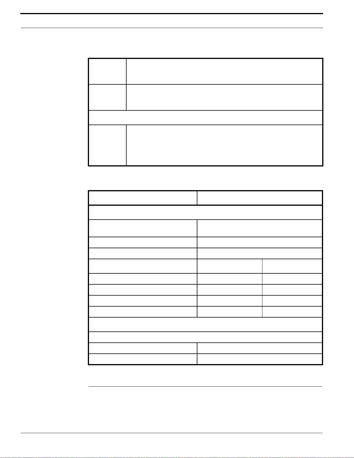
Specifications
For UL-compliant installations, refer to UL Compliance on page 96.
Enclosure Specifications
Enclosure Specifications
Physical
dimensions
Operating
environment
Humidity
range
Thermal air
cooling
Power (Door strikes powered separately)
Controller
powered by
Controller
power
requirements
Cabling
Host to
controller
Controller to
readers
17 inches high x 15.6 inches wide x 6.2 inches deep
(431 mm high x 396 mm wide x 158 mm deep)
+35
°F to +122°F (+2°C to +50°C)
5% to 95% non-condensing
At least 6 inches (15.2 cm) of clearance is required on all four sides of the
controller.
110/230 VAC to 12 VDC 6 Amp power supply is included.
12 AH gel-cell battery for battery backup is included.
Provided power supply meets all power requirements for this device.
Network: Category (Cat) 5 cable
Refer to specific reader manual for more details.
5 V Maximum cable distance 300 feet (91.44 m) with pull-up resistors
12 V Cable distance
Controller to
DIs or DOs
Use any cable with the desired number of individually shielded pairs.
10 M3000 Installation Guide
• Greater than 500 feet (152.4 m) and/or current per reader greater
than 150 mA: use Belden 8725 (or equivalent) 20-AWG, 4-pair
twisted shielded wire
• Less than 500 feet (152.4 m): use wire within 18- to 22-AWG range
Page 11

Specifications
Enclosure Specifications (Continued)
Boards and Devices
CPU board PXNplus (Refer to CPU Specifications on page 12.)
Reader
boards
Reader port power rating: 300 mA maximum per port with a total controller power
capacity of 2.7 A.
2RP or
2SRP
8RP Number supported: two (2) boards for maximum of 16 readers
Number supported: four (4) boards for maximum of eight (8) readers
Each 2RP reader board provides:
• Two (2) reader ports
• Four (4) unsupervised DIs (two (2) door alarms, two (2) REX inputs)
• Two (2) reader LED outputs
• Two (2) door strike DO relays
• Two (2) auxiliary DO relays
• Two (2) alarm shunt relays
Reader technology supported: Wiegand, Strobed, F/2F, and Supervised
F/2F
Supports keypad only and keypad/reader technology
Output devices ratings:
• Door DO (Reader LED) = 100 mA @ 12 VDC nominal
• Door strike (DO) relay = 2 A @ 30 VDC or 0.50 A @ 120 VAC
maximum
• Aux output (DO) relay = 2 A @ 30 VDC or 0.50 A @ 120 VAC
maximum
• Alarm shunt relay = 2 A @ 30 VDC or 0.50 A @ 120 VAC maximum
Each 8RP reader board provides:
• Eight (8) reader ports
• One (1) digital output (reader LED) per reader port
Reader technology supported: F/2F or Supervised F/2F
Supports keypad only and keypad/reader technology
Output devices ratings: Door DO (Reader LED) = 100 mA @ 12 VDC
nominal
20DI board Number supported: one (1) to four (4) boards
Each 20DI board provides: 20 supervised digital input (alarm) points (dry contacts)
M3000 Installation Guide 11
Page 12
Introduction
Enclosure Specifications (Continued)
16DO Number supported: one (1) to four (4) boards
Each 16DO board provides 16 digital outputs.
Output devices ratings: Digital outputs: 100 mA @ 24 VDC nominal
16DOR Number supported: one (1) to four (4) boards
Each 16DOR board provides 16 relay points.
Output devices ratings: Relays: 2 A @ 30 VDC or 0.5 A @ 120 VAC maximum
Regulatory Information
Listings FCC Class A
UL 1076
UL 294
CE
Refer to Regulatory Information on page 93 for more information.
CPU Specifications
PXNplus CPU Board
Communications interfaces
Network 10/100 MB Ethernet, on-board Ethernet RJ-45
connection, TCP/IP
Network: Static IP Supported
Network: DHCP Supported
CPU specifications Type 2 SIMM Type 3 SIMM
Operating system uClinux 2.6 uClinux 2.6
Processor Xilinx MicroBlaze Xilinx MicroBlaze
RAM 32 MB 64 MB
FLASH memory 32 MB 32 MB
Host Application and Capacities
All currently supported OnGuard versions
Badge capacity 28,000
Offline transaction capacity (number of logs) 50,000
Minimum Supported Board Levels for the PXNplus CPU Board
If the controller board contains a 4- or 5-digit numeric date code, it can be used with the PXNplus
CPU board.
12 M3000 Installation Guide
Page 13

Minimum Supported Board Levels for the PXNplus CPU Board
If the controller board shows a 2-digit alpha date code, refer to the table below for the minimum level
required.
Minimum Board Level Required for Use With the PXNplus CPU Board
Board Part Number Date Code
Power/Communications 110064001 IZ September 1999
2RP 110063001 DY April 1998
2SRP 110101501 No minimum level required
8RP 110100501 FY June 1998
20DI 110072003 IX September 1997
16DO 110071001 GZ July 1999
16DOR 110078001 No minimum level required
Backplane 110061001 Revision C
a. The first letter identifies the month where A=January, B=February, and so on. The second letter identifies
the year where Z=1999, Y=1998, and the sequence continues with each previous letter representing the
previous year.
The date code format for the years 2000 through 2007 was: WWYY (WW=week, YY=year) followed by
a letter indicating the manufacturing facility.
Example: “3903H” means week 39 of year 2003, manufactured in Hickory.
The date code format currently in use is: YYDDD (YY=year. DDD=day) followed by a letter indicating
the manufacturing facility,.
Example: “12053H” means day 53 of year 2012, manufactured in Hickory.
a
M3000 Installation Guide 13
Page 14

Introduction
14 M3000 Installation Guide
Page 15

CHAPTER 2 Installation, Planning, and Mounting
The following is a basic outline for installing and setting up your M3000 system. Some steps may
have been done for you depending on what you ordered. Some steps are optional, depending on the
additional equipment you plan to use. These steps are noted.
• WARNING! • Do not apply power to any component until the installation is complete.
Damage to components may occur if power is incorrectly applied.
1. Determine the cable clamps needed and obtain them before starting the installation.
During the installation, remember to:
• Label all connections/cables for ease of maintenance.
• Leave enough slack in the wiring so the cables can be “dressed”. This minimizes
interference during board removal or replacement.
2. Unpack your system. Refer to Introduction on page 9.
3. Mount the enclosure. Refer to Mounting on page 17.
4. Connect AC power to the power supply. Refer to Connecting the AC Input Power to the M3000
on page 25.
5. Mount and install the battery backup. Refer to Installing the Battery Backup, AC Fail, and Low
Battery on page 27.
6. Wire up the Power/Communications board. Be sure to configure and verify the switch settings.
Refer to Power/Communications Board on page 23.
7. If using networked controllers, verify that your network is up and running.
8. Install and wire up the PXNplus CPU board. Be sure to configure and verify the jumpers. If this
is a network controller, plug in the network cable. Refer to PXNplus CPU Board on page 31.
9. Install the reader board(s) into the enclosure and wire up the readers to the controller. Be sure to
configure and verify the switch settings, jumpers, and/or resistor packs. Refer to Reader
Processing Boards on page 37.
10. If using digital inputs (DIs), insert the DI board into the enclosure and wire the DIs to the board.
Be sure to configure and verify the switch settings. Refer to 20DI Board on page 71.
11. If using digital outputs (DOs), insert the DO board into the enclosure and wire the DOs to the
board. Be sure to configure and verify the switch settings. Refer to 16DO and 16DOR Boards on
page 74.
12. Test the wiring before you apply power. Refer to Pre-Power Up Testing on page 79.
M3000 Installation Guide 15
Page 16

Installation, Planning, and Mounting
13. Configure your controller. Configure the controller using the Integrated Configuration Tool.
Refer to Controller Firmware Tools on page 81.
Safety
Radio Interference
• WARNING! • This is an FCC Class A product. In a domestic environment, this product may
cause radio interference, in which case the user may be required to take
adequate measures.
Electrostatic Discharge (ESD) Precaution
• WARNING! • Circuit board components are vulnerable to damage by electrostatic discharge
(ESD). ESD can cause immediate or subtle damage to sensitive electronic
parts. An electrostatic charge can build up on the human body and then
discharge when you touch a board. A dischar ge can be produced when walking
across a carpet and touching a board, for example. Before handling any board,
make sure you dissipate your body’s charge by touching ground. This
discharges any static electricity build-up.
General Installation Rules
• WARNING! • This equipment is to be installed, maintained and serviced by authorized
service persons only.
The authorized installation contractor should comply with the following rules:
• Neatly label cables at both ends.
(For example, labels should include: controller address number/device or reader number)
• Use individually shielded pairs of cables only. All wiring must comply with local, state, and
federal electrical codes and fire codes.
• Obey all national, state, and local electrical and safety codes.
• Obtain any required permits and/or inspections. Contact the local fire marshal for assistance if
necessary.
• Safety of customer personnel is the primary consideration of the installation.
• Neatly dress and tie or lace all wiring in a professional manner.
• Gather together and tape all unused conductors in multiple conductor cables.
• Shield all cabling and terminate properly.
16 M3000 Installation Guide
Page 17

Observing Noise Prevention Procedures
Observing Noise Prevention Procedures
Signal Transmission
• Where practical, keep cables well separated from each other. Separate power cables from signal
cables.
• Keep the break-out at the ends of signal cables as short as possible.
• Ground all shield drain wire(s) at the M3000 controller using the grounding studs provided
outside the cabinet enclosure.
• For communication cables between controllers, ground shield to the upstream controller only.
• WARNING! • Do not ground both cable ends.
Cable Routing
Keep cabling at least 1 foot (30.5 cm) away from any power line or other AC voltage source.
Exercise caution when locating cables and M3000 components near any other equipment that may
cause electrical interference (noise). Examples of electrical and electro-magnetic noise sources are:
• Fluorescent lighting and neon fixtures.
• Power distribution panels, including wiring, transformers, generators, and alternators.
• Motors that drive machinery, such as air conditioners, elevators, escalators, large blowers, and
machine tools. Electromagnetic equipment such as degaussers, magnetic chucks, etc.
• Control equipment (relays) for machinery and other switching devices that carry or switch large
currents.
• Radio and television receivers and transmitters.
• Signal generators and intercom systems.
• Radar transmitting equipment.
• Arc welders, electrodischarge machinery, and related equipment.
• RF induction heaters.
Cable Length
• Minimize long parallel cable runs since they increase the likelihood of interference between
signal cables and electrical interference sources.
• Avoid excess cable length between the M3000 controller and the optional equipment, such as
readers and digital outputs, to reduce signal degradation due to external effects.
Mounting
Be sure to read the mounting and handling guidelines below before beginning to mount the controller.
Mounting and Handling Guidelines
Comply with the following guidelines:
M3000 Installation Guide 17
Page 18

Installation, Planning, and Mounting
• Locate the host computer and the M3000 controller in areas secure from any disruption to data
communications or tampering.
• Clean and clear all mounting areas of corrosive gases and airborne metallic particles. Avoid
installing near photocopiers due to contamination from toner particles.
• Protect the M3000 from hazardous (high) voltages.
• Mount the M3000 on a vertical surface with at least 6 inches (15.2 cm) clearance on all four sides
to support thermal air cooling.
• Locate the M3000 in a place that provides dedicated AC earth ground. The M3000 must be earth
grounded.
• Keep interior and exterior housing of all M3000 cabinets and other components free of wire
remnants.
• Avoid temperatures outside range specified for M3000 operating environment (refer to
Specifications on page 10). Do not leave boards or other components in direct sunlight.
• To avoid mechanical damage, do not drop or stack boards.
• Do not subject printed circuit boards to electrostatic discharge.
Mounting Instructions
The enclosure can be mounted in one of two ways
• Directly to the wall, or
• Into a standard Electronics Industries Alliance (EIA), 19-inch open frame IT Rack.
Wall Mounting
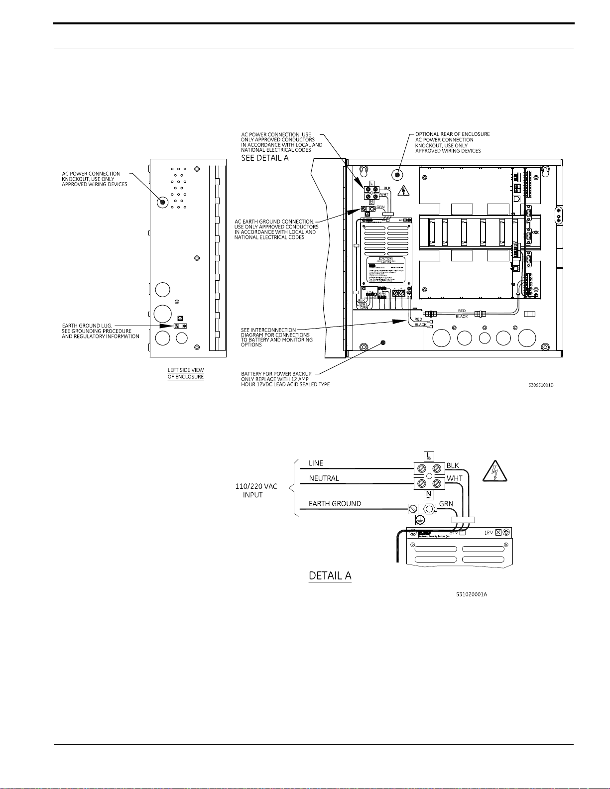
Mount the controller enclosure using the following steps and referring to figure M3000 Controller
and Components Assembly Drawing - Wall Mounting on page 19.
• WARNING! • Do not apply power to any component during installation. Damage to
components may occur if power is incorrectly applied.
1. Remove the packing material from the enclosure.
2. Using the template provided, mark and drill four mounting holes.
3. Using customer furnished 1/4-in. (6 mm) threaded lag bolts or equivalent and washers, secure the
enclosure to the wall.
4. If required, install cable conduit to the M3000 enclosure knockout holes.
5. The enclosure has knockout holes on the sides, bottom, and back; the cable is pulled through
these holes. To open the holes, strike the knockouts from the outside of the enclosure.
6. Fit and tighten a strain relief clamp in each knockout hole to be used.
• WARNING! • The M3000 must be earth grounded.
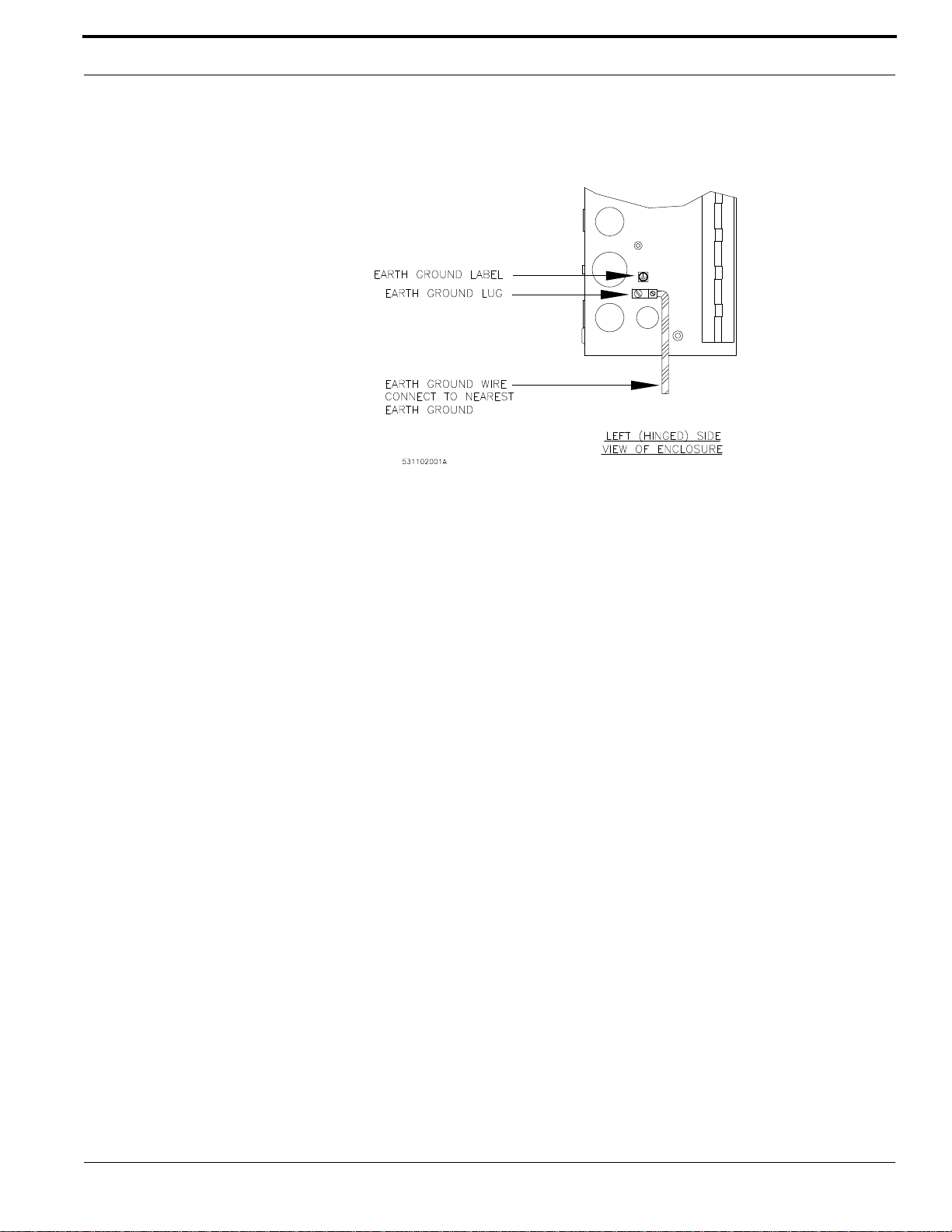
7. Find the nearest earth ground (such as an electrical box or ground bus). Run wire from the
M3000 enclosure ground terminal (top left of enclosure) to the earth ground point. Use wire size
in accordance with local and national electrical codes.
18 M3000 Installation Guide
Page 19
Mounting
M3000 Controller and Components Assembly Drawing - Wall Mounting
Wiring AC Power Through the Terminal Block – Detail A
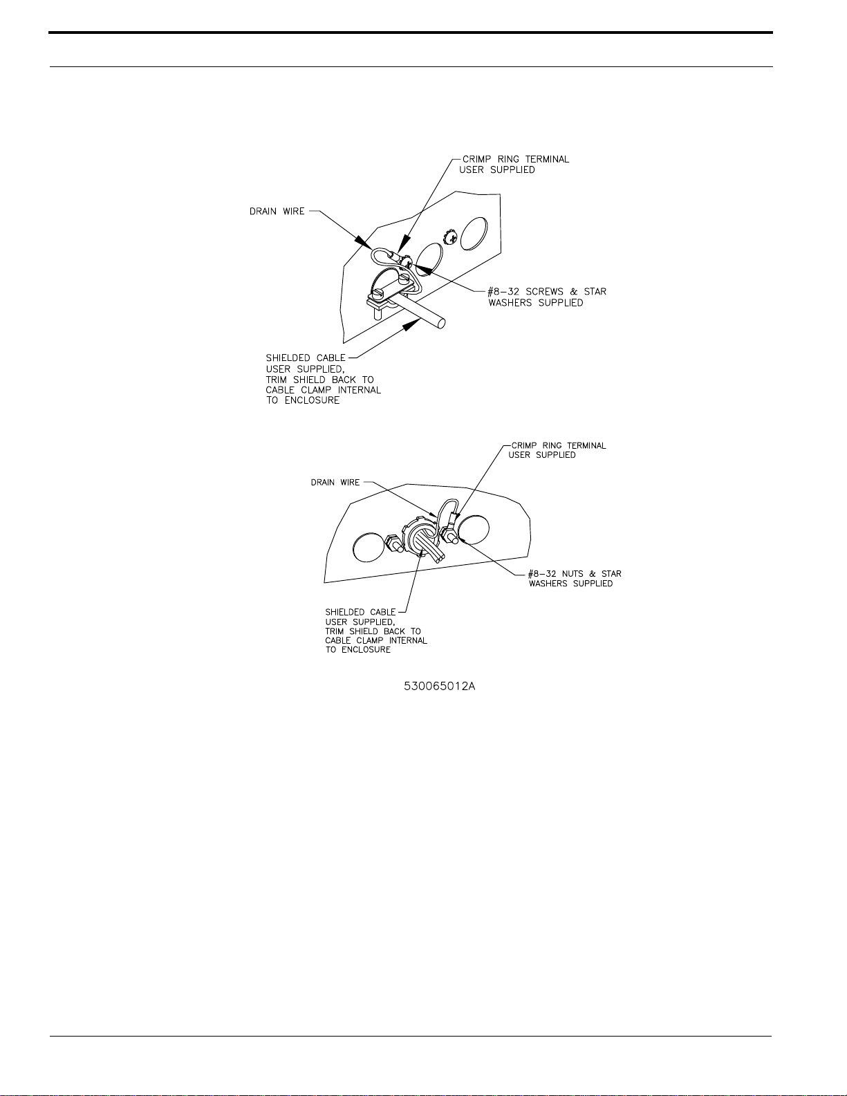
Note: All cables connected to the M3000 must be shielded with the shield terminated as
shown below.
M3000 Installation Guide 19
Page 20
Installation, Planning, and Mounting
s
Typical Installation Using Shielded Cable/drain Wire - Outside and Inside the Enclosure
Outside the enclo
Inside the enclos
8. Use the #8-32 SEMS screw and #8 flat washer provided to secure the ground lug.
20 M3000 Installation Guide
Page 21
Mounting
Earth Ground Connection
Note: The Power/Communications board must be in the far right slot and the CPU board must
be in the second right slot next to the Power/Communications board. Refer to figure
Location and Grounding of the Power/Communications and CPU Board on page 95 for
details.
Rack Mounting
The rack mount enclosure is 19-inch, EIA compatible with the optional rack mount kit.
• WARNING! • Do not apply power to any component during installation. Damage to
components may occur.
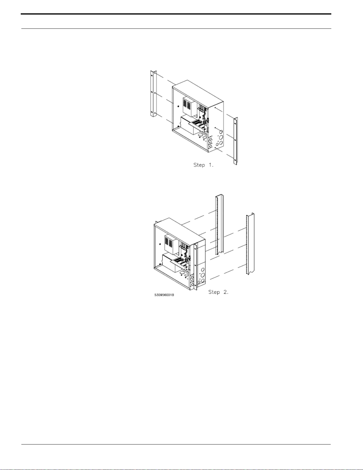
Mount the controller enclosure using the following steps and M3000 Controller - Rack Mounting on
page 22 for reference.
1. Remove the packing material from the enclosure.
2. Use the six (6) #12-24 screws provided to secure the brackets to the enclosure.
3. Secure the enclosure to the rack. This hardware is not supplied; select hardware sized to suit your
rack requirements. Sizes #10-32, #12-24, M5 or M6 screws are common rack mount hardware.
4. Install cable conduit to the M3000 enclosure knockout holes, if required.
The enclosure has knockout holes on the sides, bottom, and back; pull cable through these holes.
To open the holes, strike the knockouts from outside of the enclosure.
5. Fit and tighten approved strain relief clamp in each knockout hole to be used.
6. Find the nearest earth ground (such as, electrical box or ground bus). Run wire from the M3000
enclosure ground terminal (enclosure bottom left) to earth ground point. Use wire size in
accordance with local and national electrical codes. All cables connected to the M3000 must be
shielded with the shield terminated. (Refer to figure Typical Installation Using Shielded Cable/
drain Wire - Outside and Inside the Enclosure on page 20.)
M3000 Installation Guide 21
Page 22
Installation, Planning, and Mounting
M3000 Controller - Rack Mounting
• WARNING! • The M3000 must be earth grounded.
Note: When installing boards, the Power/Communications board must be in the far right slot
and the CPU board must be in the second right slot next to the Power/Communications
board. Refer to figure Location and Grounding of the Power/Communications and CPU
Board on page 95.
22 M3000 Installation Guide
Page 23

CHAPTER 3 Power/Communications Board
The Power/Communications board manages the power. The ICT is used for communication with the
controller. Refer to Integrated Configuration Tool (ICT) on page 81. The required communication
method is by Ethernet.
M3000 Installation Guide 23
Page 24
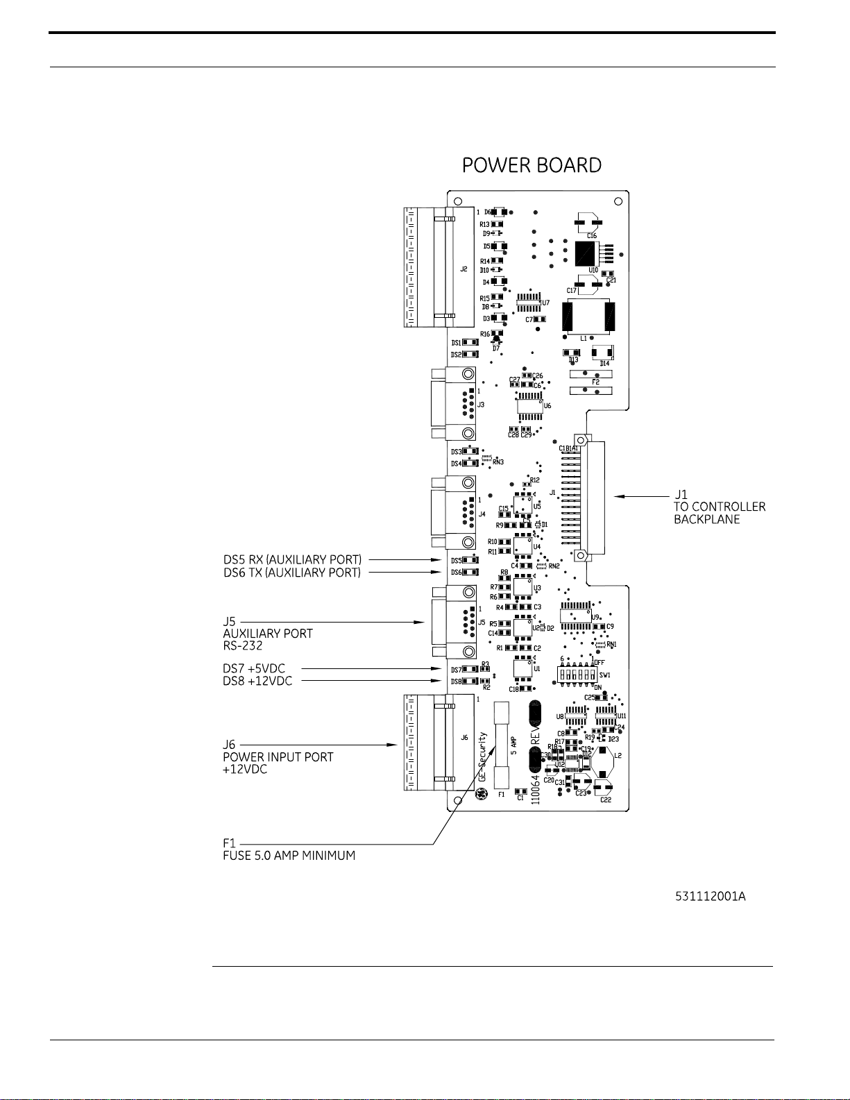
Power/Communications Board
Power/Communications Board
Layout
Power Setup
24 M3000 Installation Guide
Page 25

Power Setup
This section describes how to connect AC power to the M3000.
Connecting the AC Input Power to the M3000
Notes: A readily accessible disconnect device shall be incorporated in the building installation
wiring.
The maximum rated overcurrent protection for this device is 20 A in North America,
and 16 A in Europe, Australia, and New Zealand.
The power supply included is a 12 VDC power supply with a 6 amp current rating. This power supply
is installed in the enclosure and wired to the Power/Communications board for you.
• WARNING! • Make sure electrical power is removed before making connections to the
controller. Personal injury or death can occur if electrical power is not
removed.
To apply AC power to the power supply:
1. Follow all state, local, and national electrical codes.
2. Using the knockouts provided in the sides and back of the enclosure, connect AC power and
earth ground to the terminals provided inside the enclosure. Refer to figure Wiring AC Power
Through the Terminal Block on page 26.
Controller earth grounding (AC grounding) is a critical element for proper operation.
To test the AC power ground:
1. Using an ohmmeter, measure the resistance between the M3000 ground stud and a known good
earth ground (metal water pipe or building structural steel frame).
2. A resistance value greater than 50 ohms indicates poor AC ground.
M3000 Installation Guide 25
Page 26
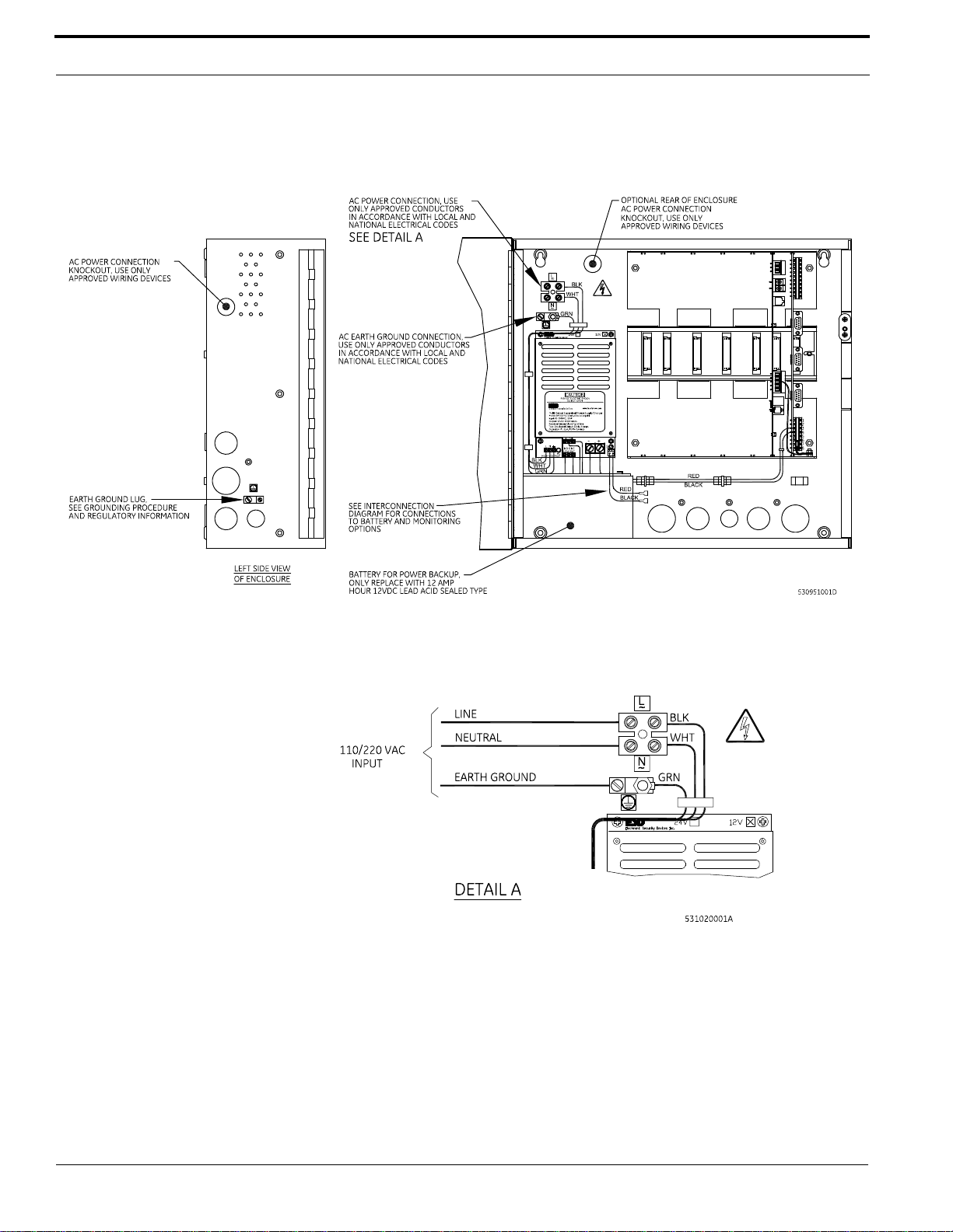
Power/Communications Board
Wiring AC Power Through the Terminal Block
Wiring AC Power Through the Terminal Block – Detail A
• WARNING! • Failure to connect the AC power and earth ground to the terminal blocks
provided will result in damage to the controller.
Use a properly sized disconnect device.
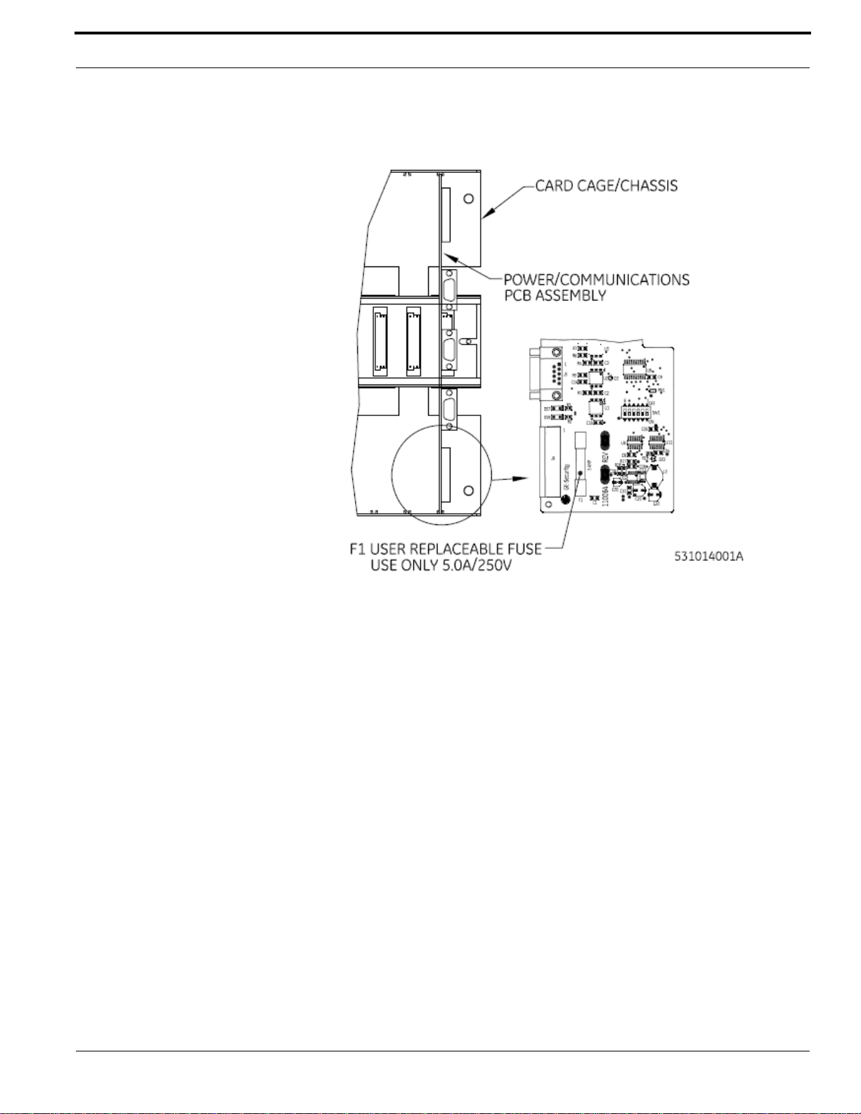
Replace fuse with the same type and rating as shown in figure Fuse Location
on the Power/Communications Board on page 27.
26 M3000 Installation Guide
Page 27
Power Setup
Fuse Location on the Power/Communications Board
• WARNING! • Good earth ground must be made before completing installation.
Installing the Battery Backup, AC Fail, and Low Battery
The battery backup acts as a temporary power supply to the M3000 when AC power is lost. The
battery included with the enclosure is 12 VDC with a 12 AH current rating. It needs to be wired to the
power supply. Refer to Troubleshooting and Maintenance on page 101 for battery removal and
installation procedures.
• WARNING! • Make sure AC input and battery backup power is disconnected prior to
installing CPU, reader, DI, and DO boards.
To install the battery
1. Unpack the battery from the shipping box.
2. Place the battery inside the enclosure below the power supply as shown in Wiring AC Power
Through the Terminal Block on page 26.
3. Remove the protective cover from the positive terminal of the battery.
4. Connect the battery leads from the power supply: Black to negative terminal and Red to positive
terminal of the battery. W iring Diagram for the Battery Backup, AC Power Fail, and Low Battery
on page 28 shows the wiring between the battery and the power supply.
• WARNING! • Replace battery with lead acid sealed 12 AH only.
M3000 Installation Guide 27
Page 28
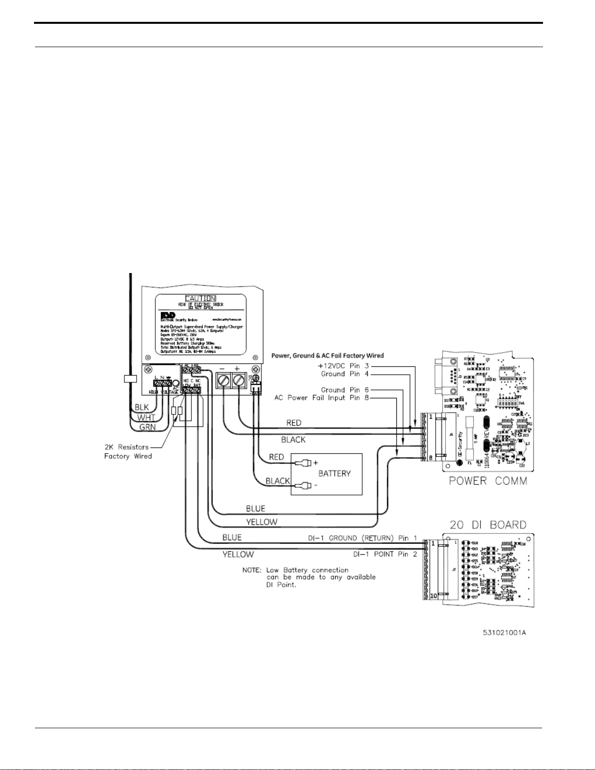
Power/Communications Board
Wiring AC Power Fail
The power supply includes a relay that monitors and signals the loss of AC power. The power fail line
is low during normal operation, and goes high when AC input power is lost.
If this option is used, connect the power supply AC power fail NC and COM terminals to the Power/
Communications Board connector J6, pin 6 (ground) and pin 8 (AC power fail input). Refer to figure
Wiring Diagram for the Battery Backup, AC Power Fail, and Low Battery on page 28.
Wiring Low Battery Detect
The power supply includes a low battery relay to detect and signal a low battery condition (11 VDC
or less).
If this option is used, connect the power supply low battery NC and NO terminals to the 20DI Board
connector J2, pins 1 and 2. Install 2K resistors at power supply terminals. Refer to the figure below.
Wiring Diagram for the Battery Backup, AC Power Fail, and Low Battery
28 M3000 Installation Guide
Page 29

LED Indicators on the Power/Communications Board
Wiring the Auxiliary Port
The Auxiliary port J5 is used to connect the PXNplus console. The console is used for testing and
debugging purposes under direction of Technical Support.
J5 - Auxiliary Port (RS-232)
Connector J5
Pin Signal Name
1 CTS (jumped to pin 9)
2 (jumped to pin 7)
3 Ground
4 +5 VDC
5 Not used
6 TX - Transmit data
7 (jumped to pin 2)
8 RX - Receive data
9 RTS (jumped to pin 1)
LED Indicators on the Power/Communications Board
The Power/Communications board has eight (8) LEDs.
LEDs Function
LED State Description
DS1 Not Used Data received from upstream host/controller connected to primary/controller
port (Receive RX).
DS2 Not Used Data transmitted to upstream host/controller connected to primary/controller
port (Transmit TX).
DS3 Not Used Data received from downstream controller connected to secondary/controller
port.
DS4 Not Used Data transmitted to downstream controller connected to secondary/controller
port.
DS5 Flashing Data received from device connected to auxiliary port (console mode).
DS6 Flashing Data transmitted to device connected to auxiliary port (console mode).
DS7 Reserved Indicates +5 VDC is present.
DS8 Reserved Indicates +12 VDC is present.
M3000 Installation Guide 29
Page 30

Power/Communications Board
30 M3000 Installation Guide
Page 31

CHAPTER 4 PXNplus CPU Board
PXNplus CPU Board Overview and Layout
The PXNplus CPU board provides network capabilities in one board.
The following are some product highlights:
• Supports Ethernet networks.
• Supports the dual Network Interface Card (NIC).
• Supports the following network protocols: DHCP and UDP.
• Utilizes a 32-bit platform, which provides better response times and higher capacity.
• Allows for remote diagnostics.
• Provides a browser-based configuration tool. Refer to Integrated Configuration Tool (ICT) on
page 81.
Refer to the OnGuard System Administration User Guide to configure this board within the access
control software.
The layout of the PXNplus CPU board is shown on the following page.
M3000 Installation Guide 31
Page 32
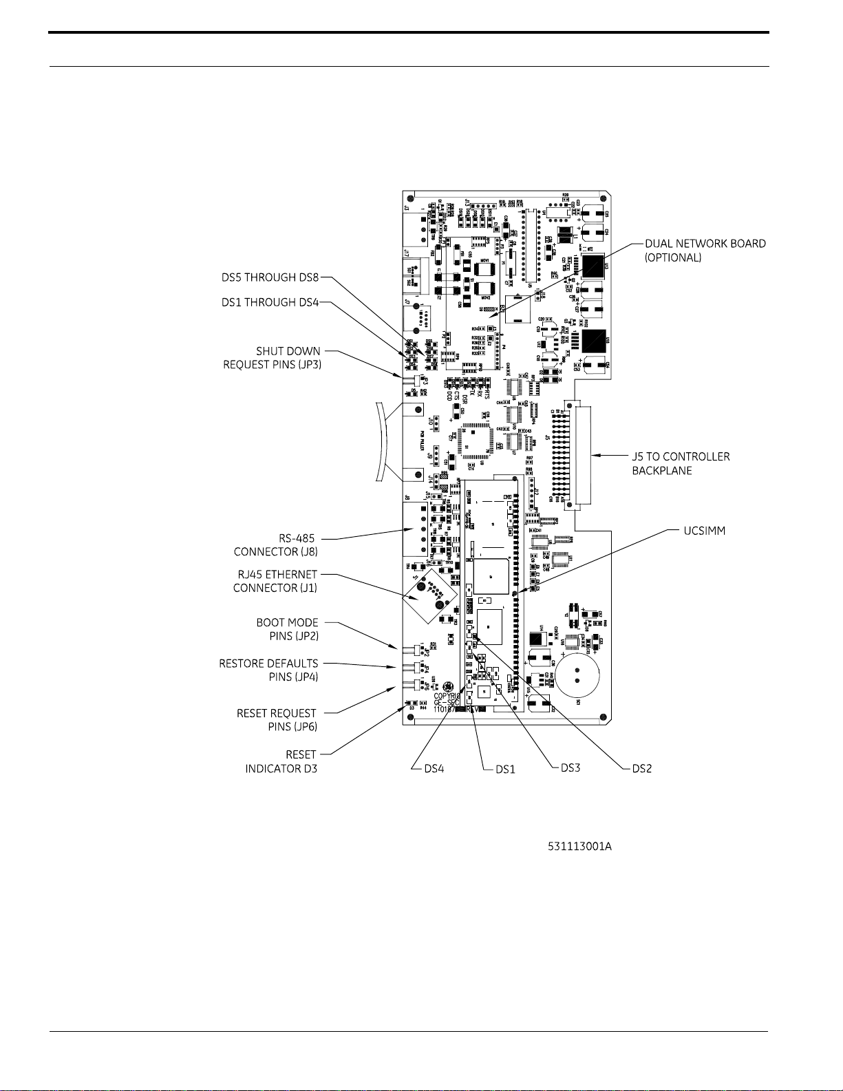
PXNplus CPU Board
PXNplus CPU Board Layout
32 M3000 Installation Guide
Page 33
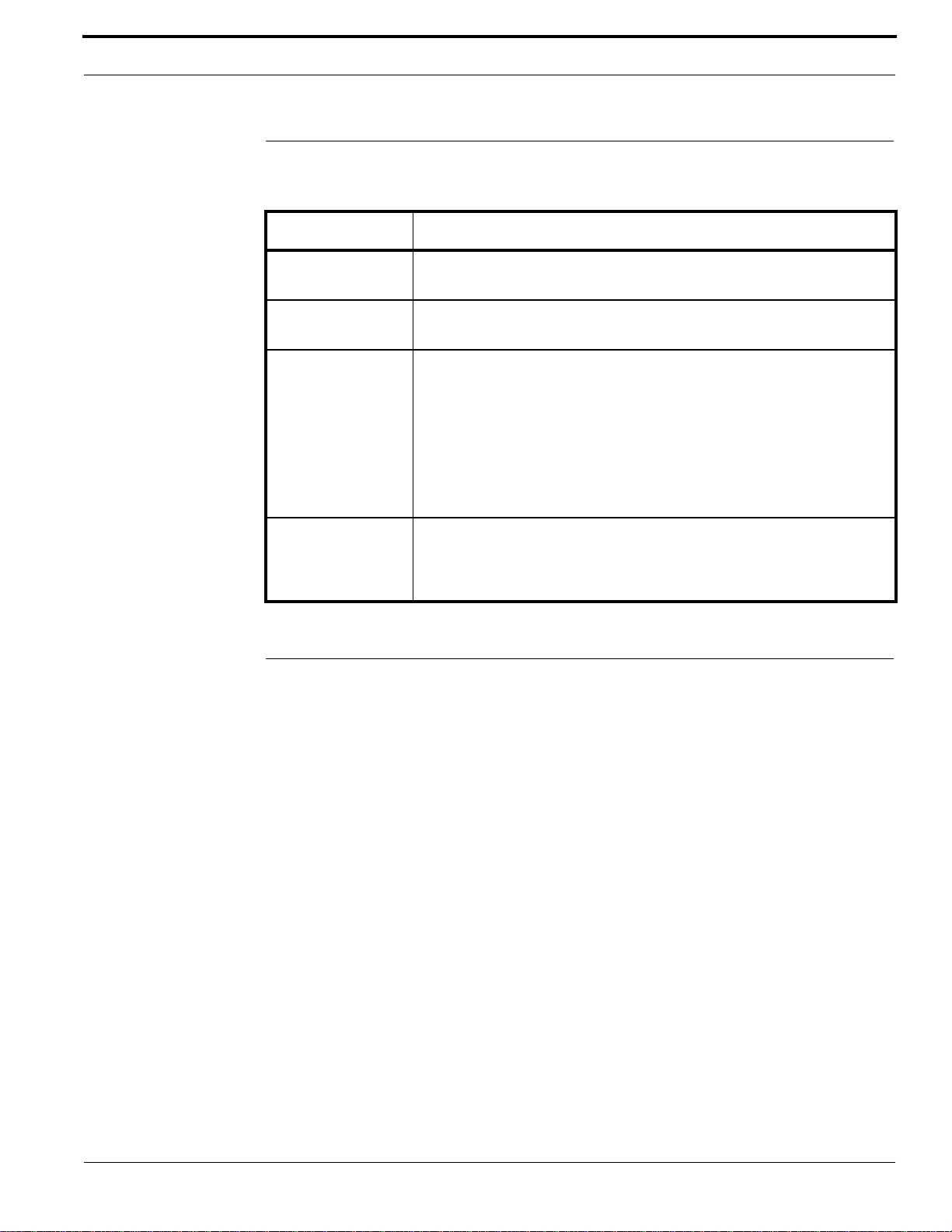
Pins and Jumpers
Pins and Jumpers
General Purpose Pins
Pins Shorting these pins...
JP2
Boot Mode
JP3
Shutdown requested
JP4
Restore Defaults
JP6
Hardware Reset
This function is for manufacturing and catastrophic failure recovery
only!
See Safe Shutdown Procedure for the PXNplus CPU Board on page 34.
Returns the configuration to the factory defaults:
• Primary Connection Type: Ethernet
• IP Address: 192.168.6.6
• Mask: 255.255.255.0
• Gateway: 192.168.6.1
Short JP4 for a minimum of five (5) seconds.
Enables the Integrated Configuration Tool (ICT). For more information, refer
to Disable/Enable the Integrated Configuration Tool (ICT) on page 89.
Reboots the CPU board without properly shutting down the application.
The PXNplus board runs an operating system just like a computer. Shorting
JP6 is like pressing the Off button on your computer without using the “Shut
down” feature. The controller shuts down but not in a clean way.
Inserting and Removing the PXNplus Board
Inserting the PXNplus Board
Caution: Follow standard static prevention procedures. Refer to Electrostatic
Discharge (ESD) Precaution on page 16.
1. Disconnect power and battery backup power.
Note: When re-inserting the CPU board, the J8 connector MUST be connected at all times to
comply with CE requirements for use in the European Union. Refer to figure Location
and Grounding of the Power/Communications and CPU Board on page 95.
2. Insert the CPU board into the controller.
3. Attach the network cable.
Removing the PXNplus Board
Caution: Follow standard static prevention procedures. Refer to Electrostatic
Discharge (ESD) Precaution on page 16.
1. To safely shut down the controller operating system, refer to the Safe Shutdown Procedure for
the PXNplus CPU Board
2. Disconnect power and battery backup power.
3. Remove any connected cables.
on page 34.
M3000 Installation Guide 33
Page 34

PXNplus CPU Board
4. Carefully remove the CPU board from the controller.
Safe Shutdown Procedure for the PXNplus CPU Board
The following procedure can be performed when in normal operation mode.
1. Insert jumper JP3 for at least 3 seconds until DS1 through DS8 turn on.
DS1 through DS8 will stay on.
2. Remove JP3.
DS1 through DS8 stay on.
3. Wait for about 5 seconds.
At this point power to the CPU board may be removed or reset via JP6.
Note: The halt state lasts for approximately 40 to 45 seconds, after which the system will auto-
restart.
LED Indicators
LEDs on the PXNplus CPU Board
Normal Operation Mode is the mode that the controller is in after application updates have been
made. During normal operation, the Watchdog LED (DS6) flashes once per second.
Note: After updates are made to the controller, or power is cycled to the controller, and the
Watchdog LED (DS6) starts flashing, wait at least four (4) minutes before attempting
any button commands. During this period, the panel software is initializing and the user
buttons are not monitored. At the end of this period, DS6 turns off for one second, and
then flashes once per second to indicate that the controller is in Normal Operation
Mode. At this time, the user buttons are monitored.
• Controller offline: The controller has lost communication with the host.
• Address received: The controller received a message from the host.
• Badge read OK: The controller decoded a badge read and determined that it was a valid badge.
• Waiting for database: The controller is waiting to receive the database from the host.
• Restore defaults requested: Jumper JP4 was shorted. This requests that the defaults be restored.
The defaults are listed in table General Purpose Pins on page 33.
• Shutdown requested: Request a safe halt of all processes running in the panel. Required for safe
power down.
• eFlash image save: The newly loaded image from the eFlash transfer is being saved into the
flash. This is an activity indicator only.
• Persistence: Indicates that the controller is operating without a host. In this mode, the controller
is operating standalone until communication is re-established with the host.
• Flash write: The controller is storing database records into the flash file system. This is an
activity indicator only.
34 M3000 Installation Guide
Page 35
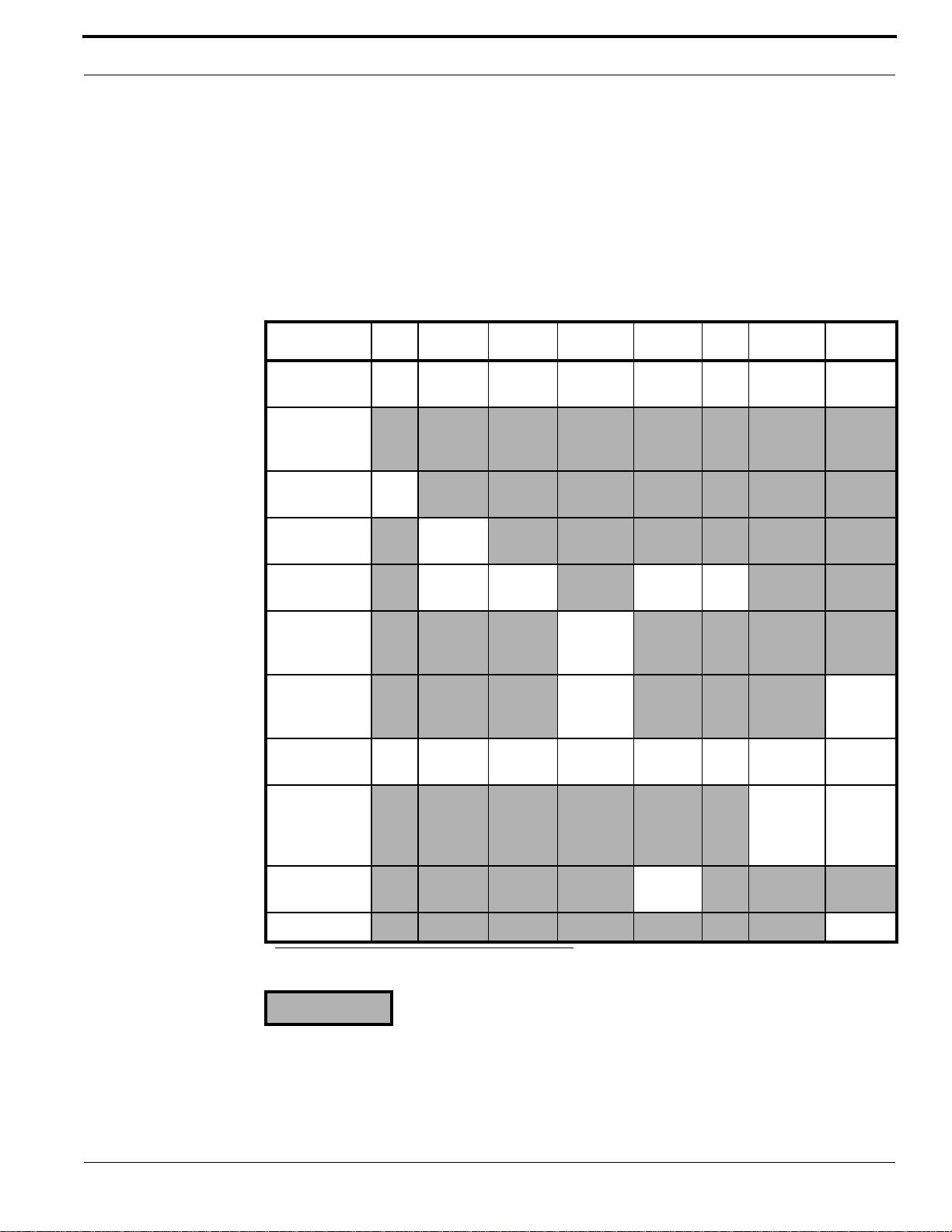
LED Indicators
• Watchdog failure mode: An internal thread failed. Details about the failure were logged
according to the log settings. The micro performs a complete reboot after this failure.
The table PXNplus CPU Board LED Normal State Transitions on page 35 shows the normal LED
state transitions.
Refer to Troubleshooting and Maintenance on page 101 for error conditions.
Refer to figure PXNplus CPU Board Layout on page 32 for the location of the LEDs.
PXNplus CPU Board LED Normal State Transitions
DS1 DS2 DS3 DS4 DS5 DS6 DS7 DS8
During power upON ON ON ON ON ON ON ON
Normal
operation
mode
Controller
offline
Address
received
Badge read
OK
Waiting for
panel
configuration
Restore
defaults
requested
Shutdown
requested
eFlash image
save
Flash Write
Persistence ON
ON
Flashes
once
Flashes
once
ON ON ON ON ON ON ON ON
Flashes
once
Flashes
once
Flashes
ON ON
a
Flashes
once
ON
Alternates
ON with
DS8
Alternates
ON with
DS7
a. For OnGuard systems DS4 blinks once per second.
= OFF
M3000 Installation Guide 35
Page 36
PXNplus CPU Board
UCSIMMPlus Board LED Indicators on the PXNplus Board
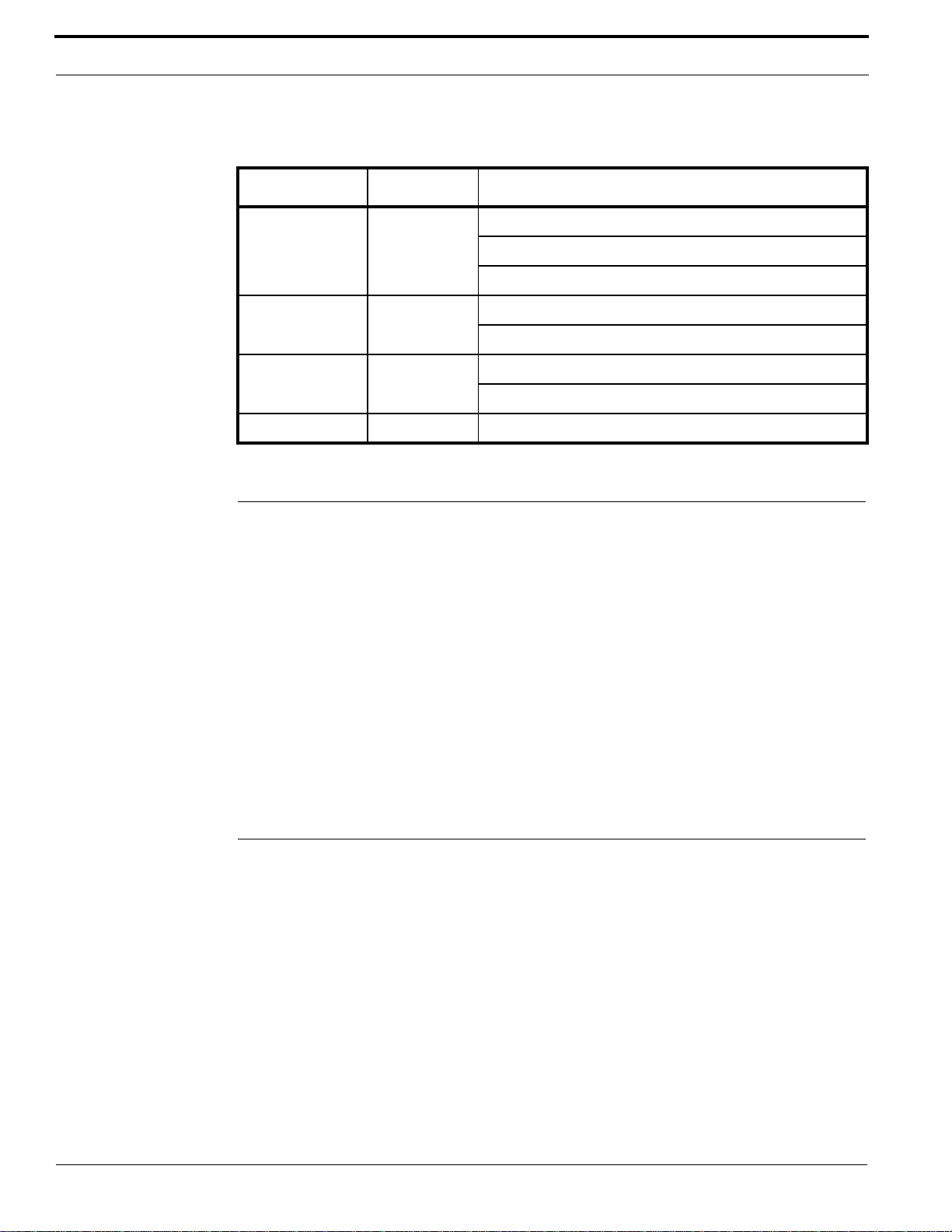
LEDs Color Purpose (Type 2 SIMM and Type 3 SIMM)
DS1 and DS5 Green ON - Link activity present.
OFF - No link activity present.
Flashing - Network activity detected.
DS2 and DS6 Yellow ON - 100 Mbps
OFF - 10 Mbps
DS3 and DS7 Red ON - Full duplex
OFF - Half duplex
DS4 and DS8 Red ON – Collision
Important Information for Firewall Users
If your installation requires any controller and its corresponding host to communicate through a
firewall, then the firewall must be configured to allow for connections through a specific port.
When OnGuard is used with the products listed below, firewall port 3001 (default) must be open.
• Integrated Configuration Tool
• DirecDoor
• M5PXNplus
• M2000PXNplus
• M3000PXNplus
Note: The default port (3001) can be changed using the ICT. Refer to Integrated Configuration
Tool (ICT) on page 81.
Configuring Upstream Communications with the Host
1. Verify that you have a working network. If you need to configure before your network is running,
go to step 3.
2. Connect the network cable into J1, the Ethernet connector. Refer to Regulatory Information on
page 93.
3. Use the Integrated Configuration Tool to set the board to network use. The default for this board
is network, so you may only need minimal set up. Refer to Controller Firmware Tools on page
81.
36 M3000 Installation Guide
Page 37

CHAPTER 5 Reader Processing Boards
The M3000 controller supports the following types of reader processing boards:
• 2RP Board on page 37
• 2SRP Board on page 49
• 8RP Board on page 64
Only one reader board type can be used at one time, for a maximum of:
• Four (4) 2RP boards (for support of up to eight (8) readers),
• Four (4) 2SRP boards (for support of up to eight (8) supervised readers), or
• Two (2) 8RP boards (for support of up to 16 readers).
2RP Board
Each 2RP reader board provides:
• Two (2) reader ports,
• Four (4) unsupervised DIs with
– two (2) door alarms, and
– two (2) REX inputs,
• Two (2) reader LED outputs,
• Two (2) door strike DO relays,
• Two (2) auxiliary DO relays, and
• Two (2) alarm shunt relays used to shunt out external alarm inputs.
Please note the following:
• Each 2RP board is limited to only one (1) type of reader technology: Wiegand, Strobed, F/2F, or
Supervised F/2F.
• Both readers connected to the board must use the same voltage.
• In Supervised F/2F mode, the exit request and door alarm contact wiring is terminated at the
reader.
• If alarm points are not available on the reader, use alarm points on the controller.
M3000 Installation Guide 37
Page 38
Reader Processing Boards
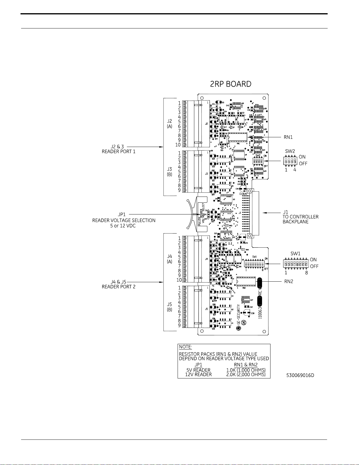
2RP Board Layout
2RP Board Layout
38 M3000 Installation Guide
Page 39
2RP Board
Setting DIP Switches
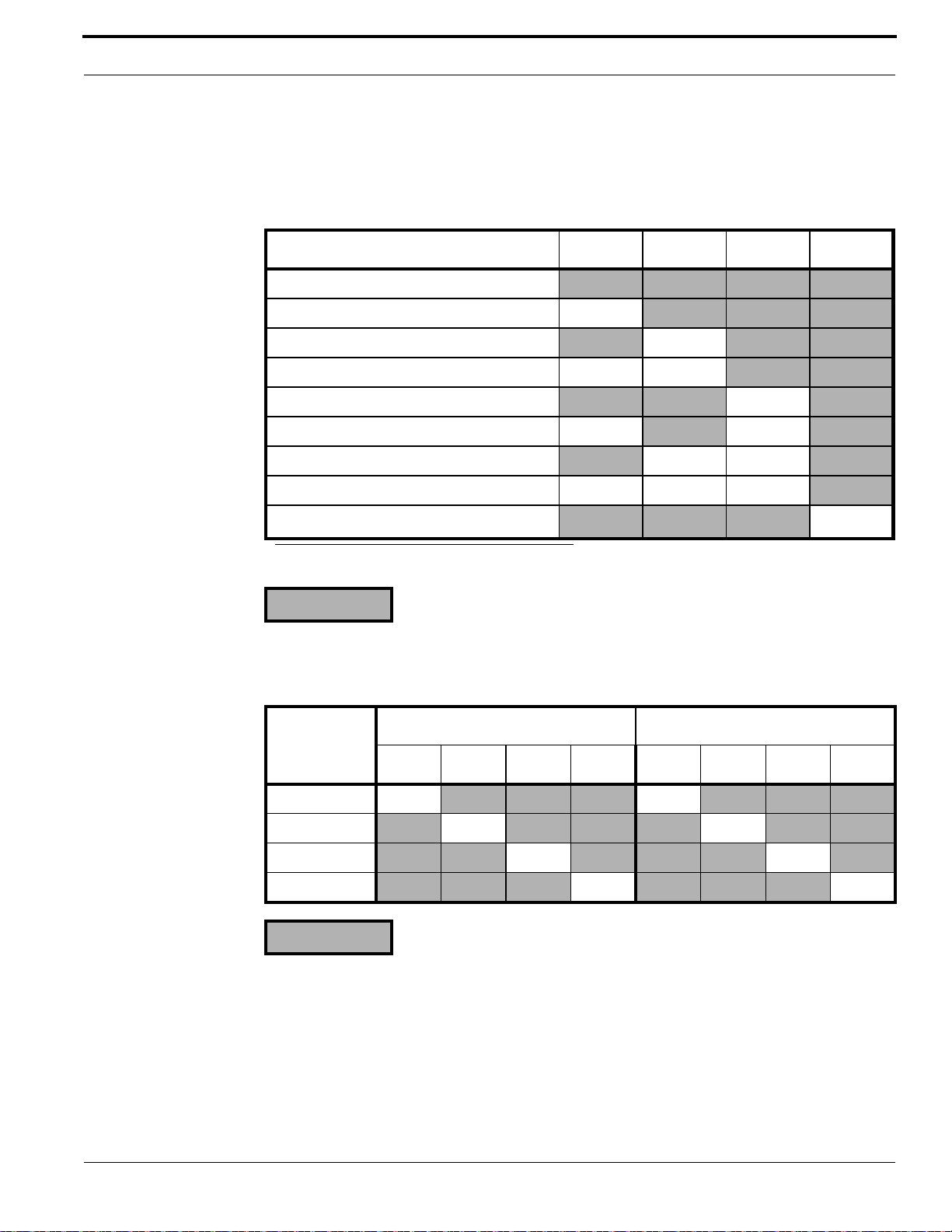
Set DIP switches as described in the following table before installing and wiring the 2RP board.
Reader Technology
Reader Technology SW1-1 SW1-2 SW1-3 SW1-4
Not Valid
Reserved ON
Reserved ON
Magstripe - Reversed Strobed ON ON
Magstripe - Water-Mark ON
Magstripe - Supervised F/2F (default) ON ON
Magstripe - Strobed ON ON
Magstripe - F/2F ON ON ON
Wiegand - <format>
a. Use the OnGuard application to configure the specific Wiegand card formats.
= OFF
a
ON
2RP Reader Board Address Settings
SW1- SW2-
Reader Board
1ON
2 ON ON
3 ON ON
4 ON ON
= OFF
56781234
ON
Note: Switches SW2-5, 6, 7, and 8 are not used.
Setting Reader Voltage
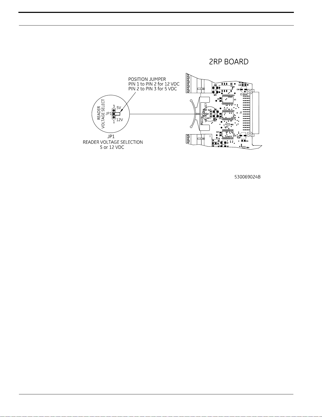
Select the proper reader voltage by placing the jumper on JP1. Refer to the figure below for details.
Both reader ports are set to the selected voltage.
M3000 Installation Guide 39
Page 40
Reader Processing Boards
Setting 2RP Reader Voltage
Installing Resistor Packs
Insert the proper resistor packs in RN1 and RN2. Be sure you insert the correct resistor pack for the
reader voltage selected. Both resistor packs must be the same since the voltage for both readers must
be the same. Refer to the figure below for details.
40 M3000 Installation Guide
Page 41
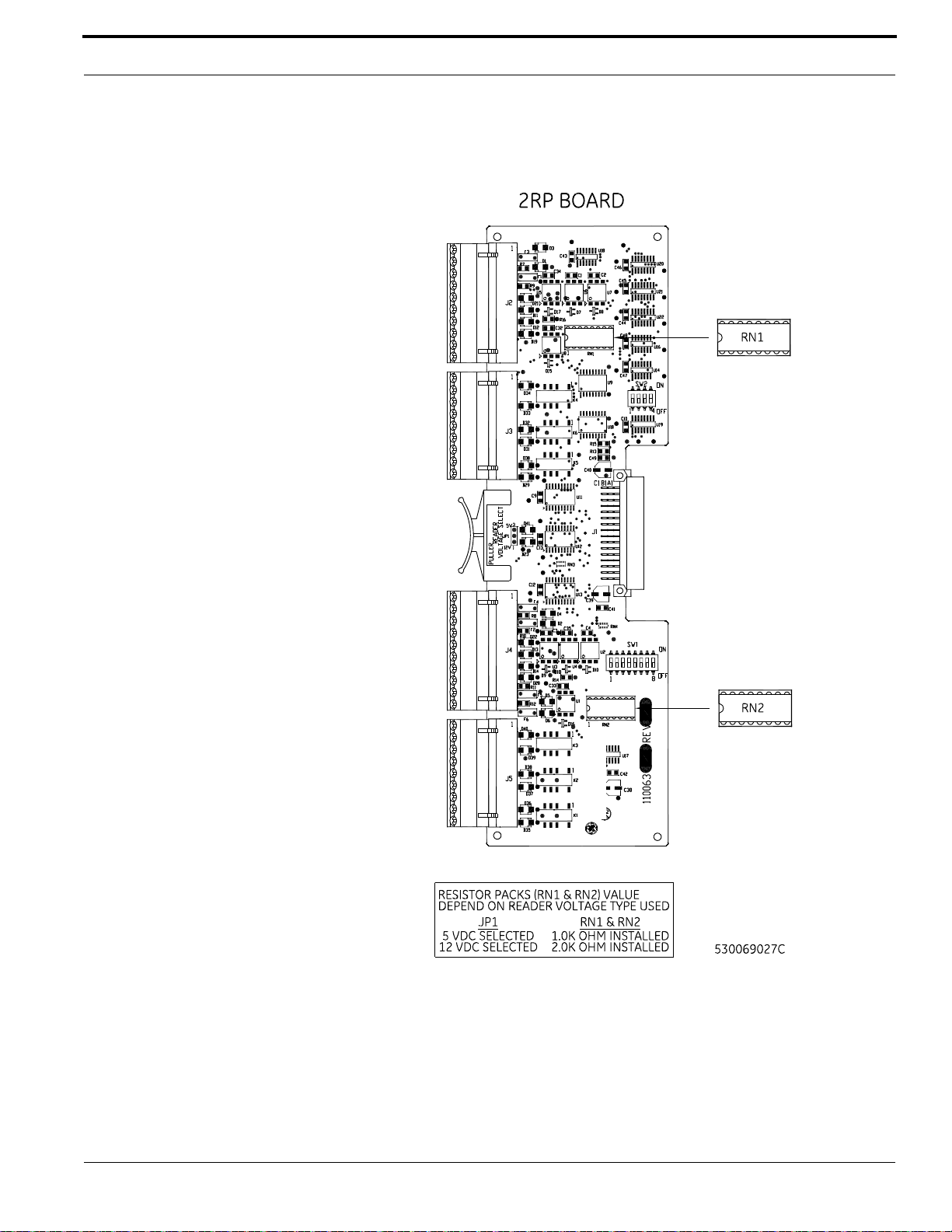
2RP Board
Installing 2RP Resistor Packs
Wiring Readers
If wiring a 12 V reader that uses 5 V data lines, note the following conditions before continuing:
• Set the reader voltage (JP1) to 5 V.
M3000 Installation Guide 41
Page 42

Reader Processing Boards
• Wire the Reader power lead to the Power output port (J6) on the Power/Communications board
instead of wiring it to the 2RP board.
To wire a reader:
1. Mount the reader. Refer to the manual that came with your reader for specific mounting
instructions.
2. Run cable from the reader to the controller. Bring each reader cable through the appropriate
knockout hole in the controller enclosure. Allow some slack wire for servicing the cables and for
plugging cable into an adjacent slot for troubleshooting.
3. Remove 8 inches (20.32 cm) of insulating material from the cable. Unwrap shielding and tie all
shields together. Connect the communications cable shield to the ground stud adjacent to the
cable entrance knockout of the cabinet enclosure. For more details, refer to figure Typical
Installation Using Shielded Cable/drain Wire - Outside and Inside the Enclosure on page 20.
4. Place the appropriate wires to the appropriate screw terminal on the 2RP reader board. Refer to
the reader wiring diagrams in this section. Pairing of cables is very important.
Important: For 12 V readers using cable runs over 500 feet (152.4 m), you must install pull-up
resistors (470 ohm, 1/2 watt) between Reader Data 0 and +12 VDC and between Reader Data 1
and +12 VDC. Some readers require pull-up resistors regardless of cable length. For 5 V readers,
the maximum cable distance is 300 feet (91.44 m) with pull-up resistors. Refer to your reader
manual to determine if pull-up resistors are required.
5. Label each cable end with the Controller Address Number/Device or Reader Number.
Recommended Pairing of Reader Wires - Typical Reader Cable (Use Belden
8725 twisted shielded pair or equivalent)
Pin Signal Name Typical Wire Color
1 +5 VDC or +12 VDC Reader Power Red
6
2 Ground (-) Green
7 Reader Data 1 White
4 Door DO (Reader LED) White/Black
8
3 Spare White/Green
5
a. Reader Data 0, Door DI, and Exit Request DI can be replaced or interchanged with Display DO and/or
Clock DO when required for a non-supervised keypad reader.
Reader Data 0
Door DI (Alarm input)
Exit Request DI
a
a
a
Black
White/Red
White/Yellow
42 M3000 Installation Guide
Page 43
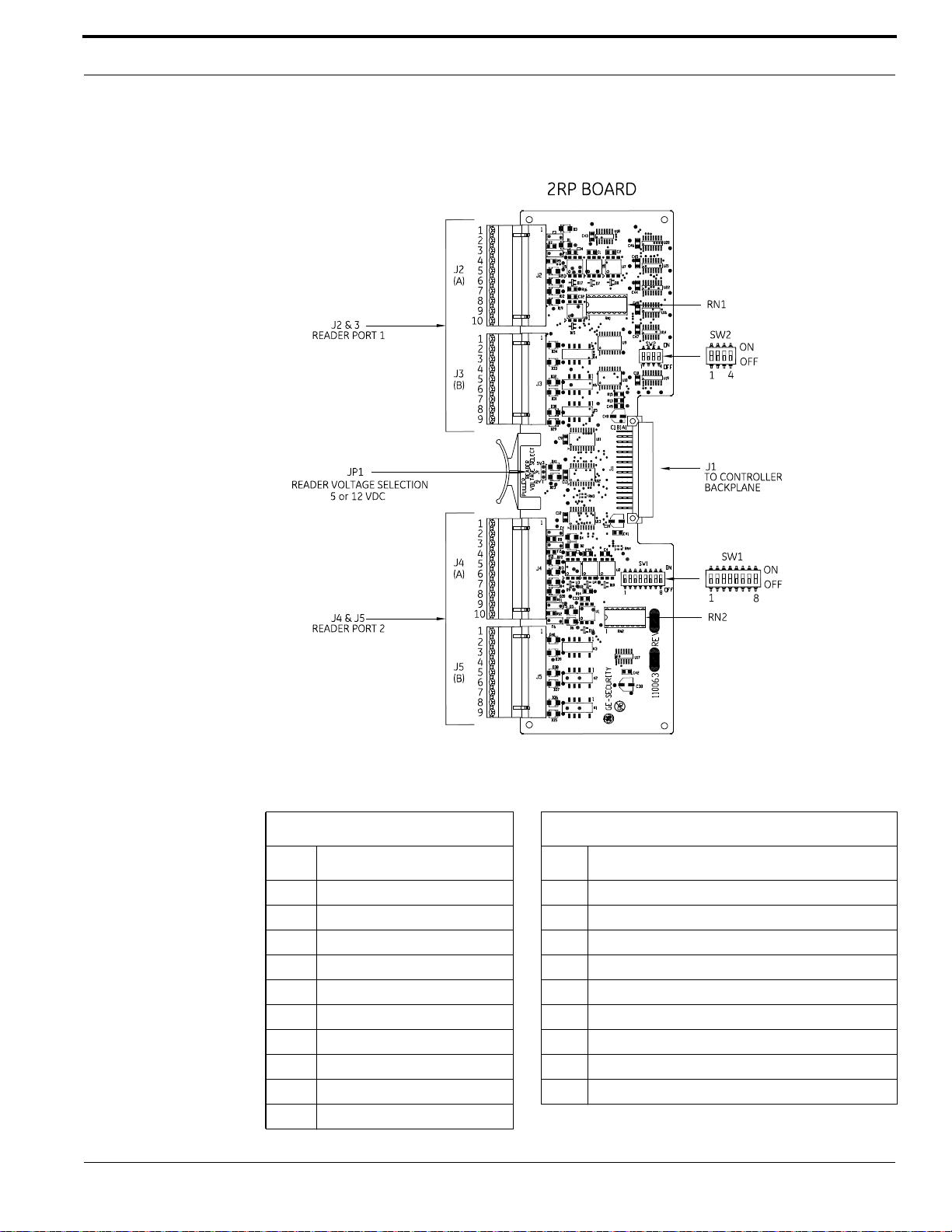
2RP Board
2RP Reader Connector Points
2RP Connector Pinouts
J2/J4 Reader Connector Pinouts J3/J5 Relay Connector Pinouts
Pin Signal Name Pin Relay
1 +5 VDC/+12 VDC 1 Door Strike Relay – Normally Closed (NC)
2 Ground 2 Door Strike Relay – Common (Com)
3 Display DO 3 Door Strike Relay – Normally Open (NO)
4 Door DO (Reader LED) 4 Auxiliary Output Relay – Common (Com)
5 Exit DI (Exit Request) 5 Auxiliary Output Relay – Normally Closed (NC)
6 Reader Data 0 6 Auxiliary Output Relay – Normally Open (NO)
7 Reader Data 1 7 Alarm Shunt Relay – Common (Com)
8 Door DI (Alarm Point) 8 Alarm Shunt Relay – Normally Closed (NC)
9 Not used 9 Alarm Shunt Relay – Normally Open (NO)
10 Clock DO
M3000 Installation Guide 43
Page 44
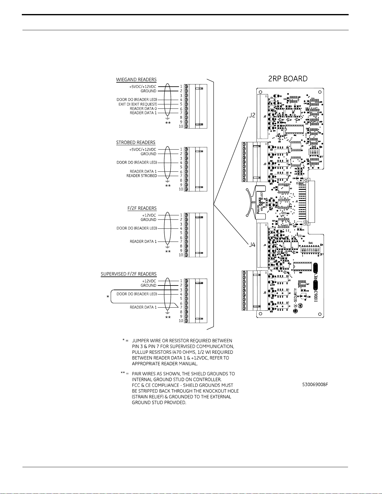
Reader Processing Boards
Wiring 2RP to Wiegand, Strobed, F/2F, and Supervised F/2F Readers
44 M3000 Installation Guide
Page 45
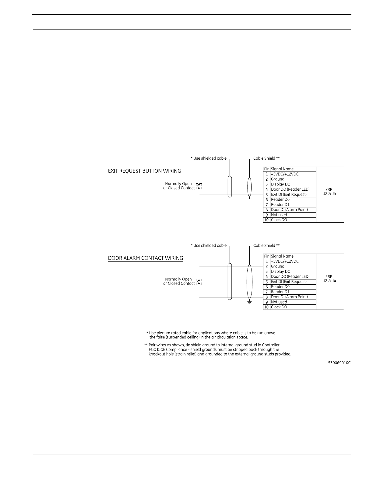
2RP Board
Wiring Digital Inputs
Each reader port has two (2) unsupervised digital inputs (DIs) which are used for door status devices
(door contacts and exit request input). Since these DIs are not supervised, they do not require end-ofline resistors.
To wire a DI:
1. Install the door contact and exit contact as required.
2. Wire the door DI between pin 2 (Gnd) and pin 8 (Door DI) and/or exit DI between pin 2 (Gnd)
and pin 5 (Exit DI) to the corresponding reader port on the 2RP board. The contact can be
Normally Open or Normally Closed.
Wiring 2RP Exit Request and Door Alarm Contact
Wiring Door Strikes
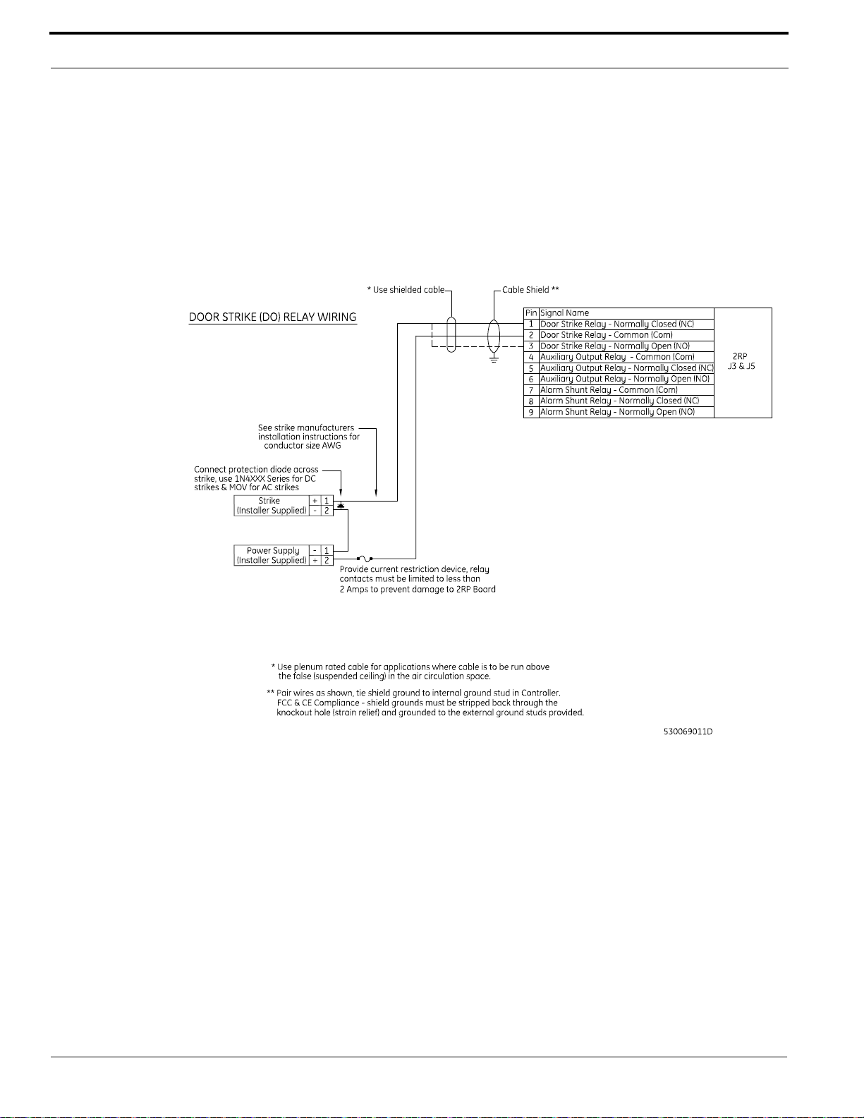
The 2RP provides a door DO relay dedicated to each reader port.
To wire a door strike:
1. Install the door strike (maximum 2 A @ 30 VDC or 0.50 A @ 120 VAC) as required.
M3000 Installation Guide 45
Page 46
Reader Processing Boards
2. Wire the door strike to the door DO (internal) relay. Normally Open or Normally Closed dry
contacts are available. Refer to figure Wiring 2RP Door Strike - Internal Relay on page 46.
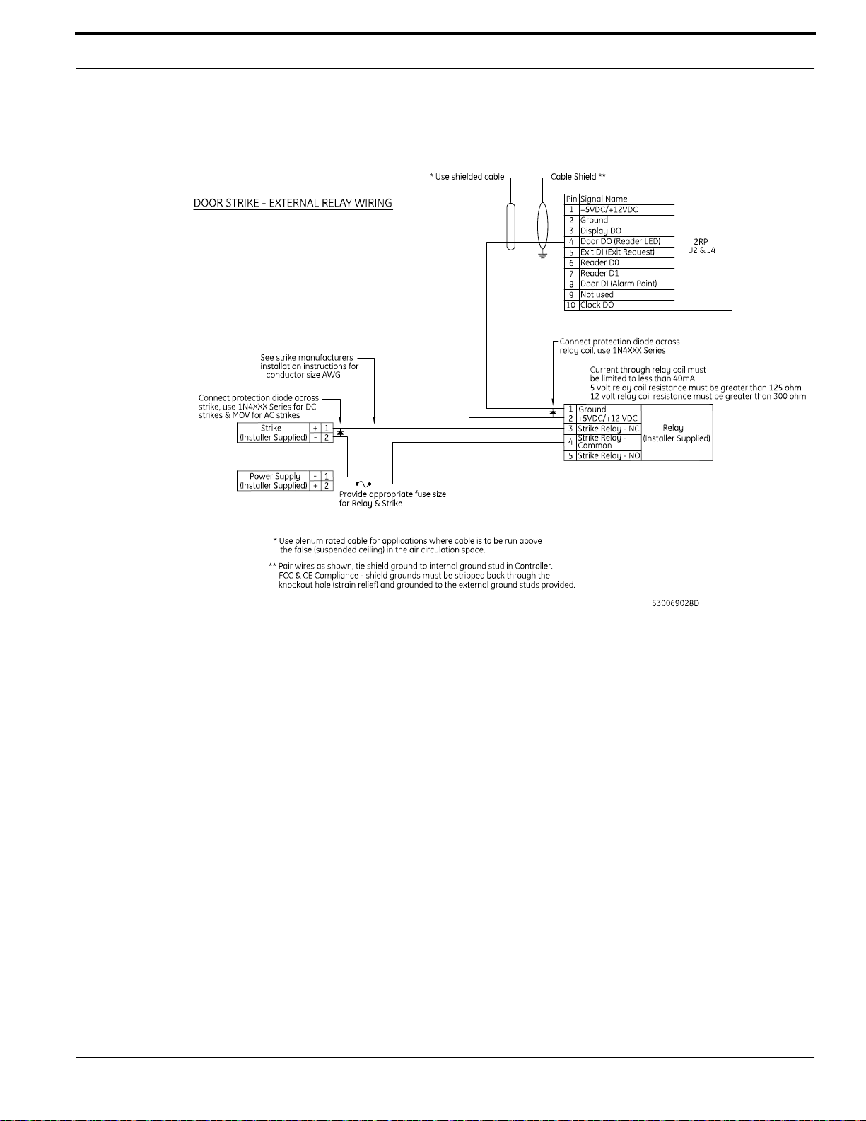
3. If required, wire the door strike to a customer supplied external relay and the 2RP board as
shown in figure Wiring 2RP Door Strike - External Relay on page 47.
4. Install a protection diode across the relay and the door strike. Use 1N4002, 1N4003, 1N4004 or
equivalent diodes for DC door strikes and metal oxide varistors (MOV) for AC door strikes.
Wiring 2RP Door Strike - Internal Relay
46 M3000 Installation Guide
Page 47
2RP Board
Wiring 2RP Door Strike - External Relay
Wiring Auxiliary DO Relays
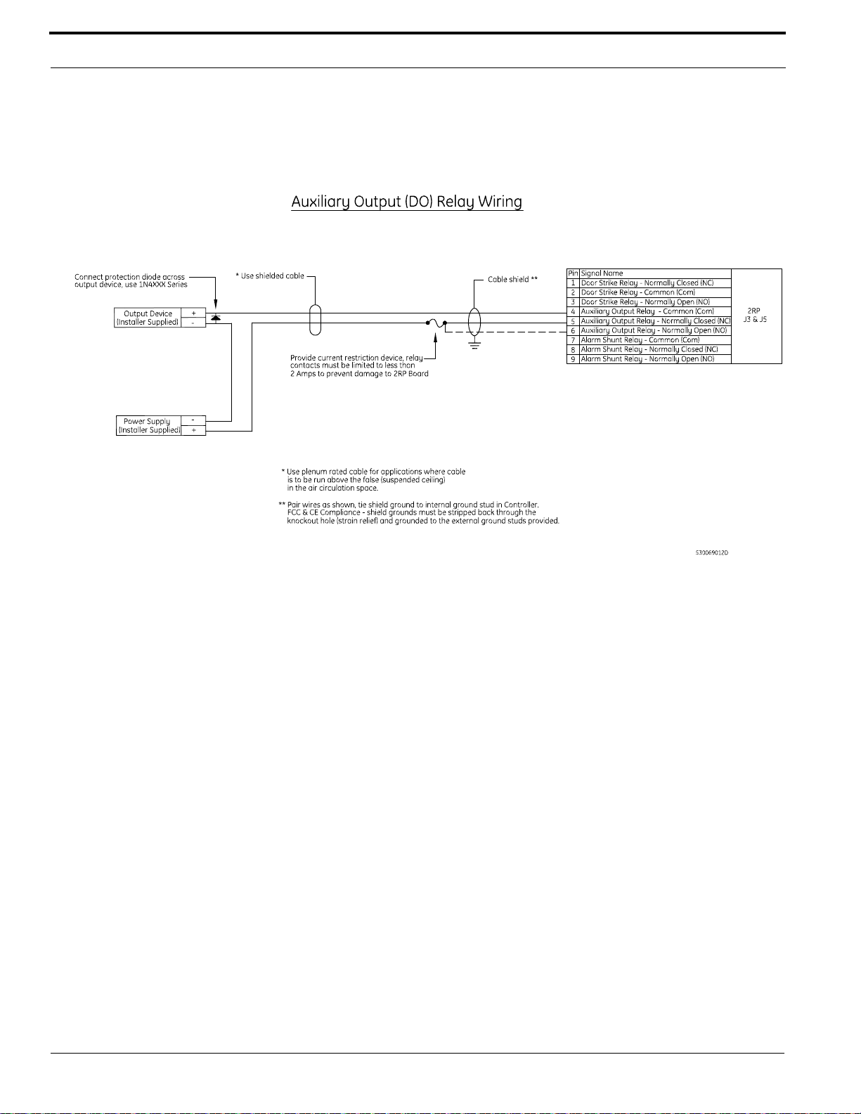
One auxiliary DO relay per reader port can be defined by the user. The auxiliary DO relay is used for
an auxiliary output device.
To wire an auxiliary DO relay:
1. Install the auxiliary output (maximum 2 A @ 30 VDC or 0.50 A @ 120 VAC) as required.
2. Wire the output device to the auxiliary DO relay. The auxiliary DO relay has either a Normally
Open or Normally Closed dry contact available (pin 4 = Common, pin 5 = Normally Closed,
pin 6 = Normally Open).
M3000 Installation Guide 47
Page 48
Reader Processing Boards
Wiring 2RP Auxiliary DO Relay
Wiring Alarm Shunt Relays
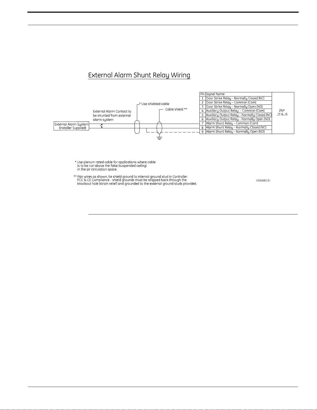
One alarm shunt relay is available per reader port. The alarm shunt relay is used to shunt (disable) an
external alarm system contact (such as burglar alarm) on a valid read or exit push button request.
To wire an alarm shunt relay:
1. Install the alarm shunt (maximum 2 A @ 30 VDC or 0.50 A @ 120 VAC), as required.
2. Wire the external alarm system to the alarm shunt relay. The relay has either a Normally Open or
Normally Closed dry contact available (pin 7 = Common, pin 8 = Normally Closed,
pin 9 = Normally Open).
48 M3000 Installation Guide
Page 49
2SRP Board
Wiring 2RP External Alarm Shunt Relay
2SRP Board
Each 2SRP board provides:
• Four (4) supervised DIs
– Two (2) alarms
– Two (2) REX inputs
• Two (2) reader LED outputs
• Two (2) door strike DO relays
• Two (2) auxiliary DO relays
• Two (2) alarm shunt relays used to shunt out external alarm inputs.
Please note the following:
• Each 2SRP board is limited to only one type of reader technology: Wiegand, Strobed, F/2F, or
Supervised F/2F.
• Both readers connected to the board must have the same voltage.
• The 2SRP board has built-in pull-up resistors to accommodate cable lengths over 500 feet
(152.4 m). External pull-up resistors are not required for the 2SRP board.
• If alarm points are not available on the reader, use alarm points on the controller.
M3000 Installation Guide 49
Page 50
Reader Processing Boards
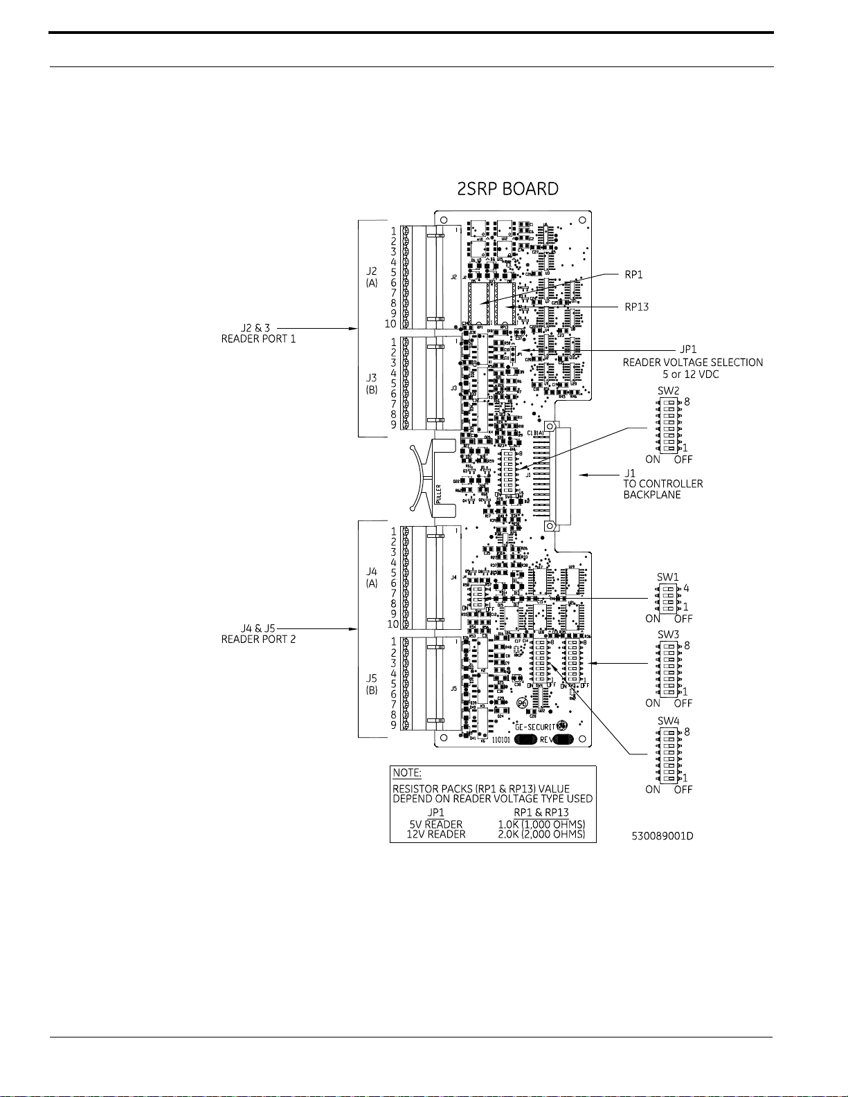
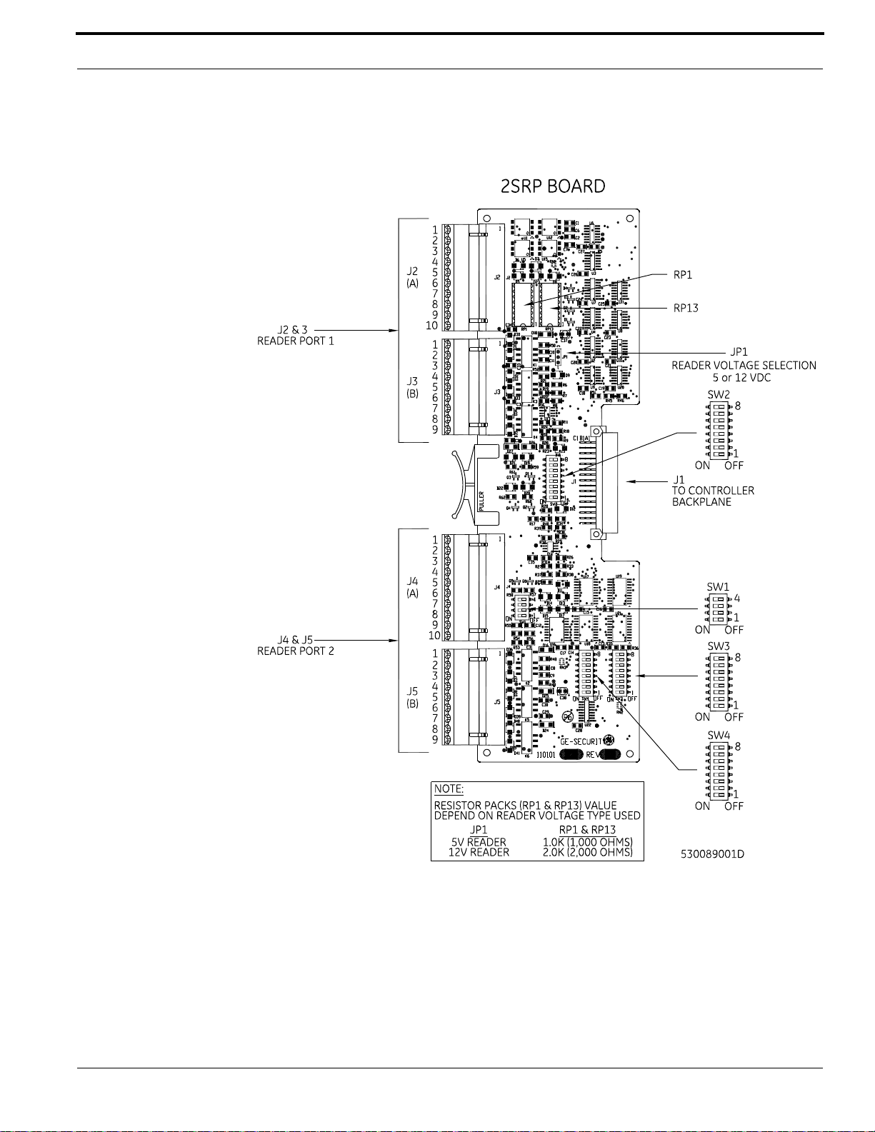
2SRP Board Layout
2SRP Board Layout
50 M3000 Installation Guide
Page 51
2SRP Board
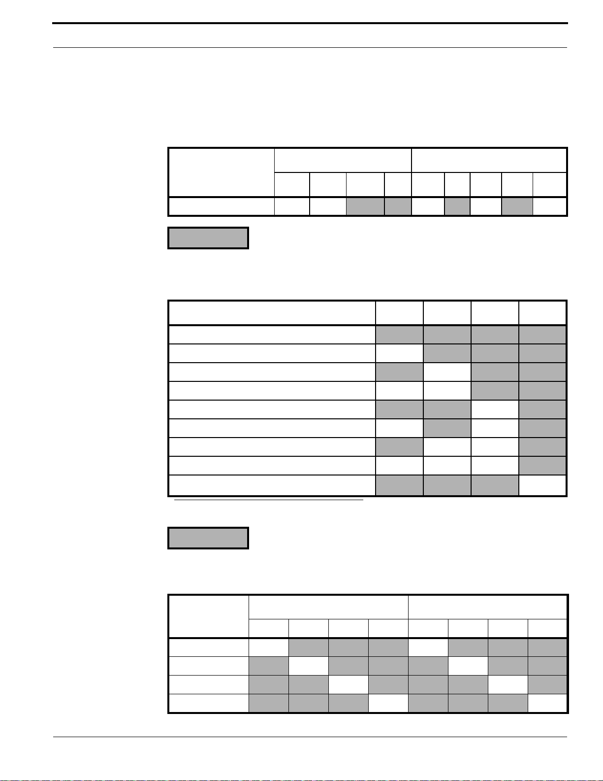
Setting the DIP Switches
Set the DIP switches as described in the tables below before installing and wiring the 2SRP board.
Supervised DI End-of-line Resistors
SW1- SW2-
1 2 3 4 1 2 3 4 5 - 8
Standard (1K, 1K) ON ON
= OFF
ON ON ON
Reader Technology
Reader Technology SW3-1 SW3-2 SW3-3 SW3-4
Not Valid
Reserved ON
Reserved ON
Magstripe - Reversed Strobed ON ON
Magstripe - Water-Mark ON
Magstripe - Supervised F/2F (default) ON ON
Magstripe - Strobed ON ON
Magstripe - F/2F ON ON ON
Wiegand - <format>
a
ON
a. Use the OnGuard application to configure the specific Wiegand card formats.
= OFF
Reader Board (2SRP) Address Settings
SW3- SW4-
Reader Board
1ON
2 ON ON
3 ON ON
4 ON ON
M3000 Installation Guide 51
56781234
ON
Page 52
Reader Processing Boards
Note: The boards must be numbered consecutively. This means that the first reader board
must be set to Address 1, the second reader board must be set to Address 2, and so on.
If they are not, the supervised DI points will not work correctly.
Special Reader Types
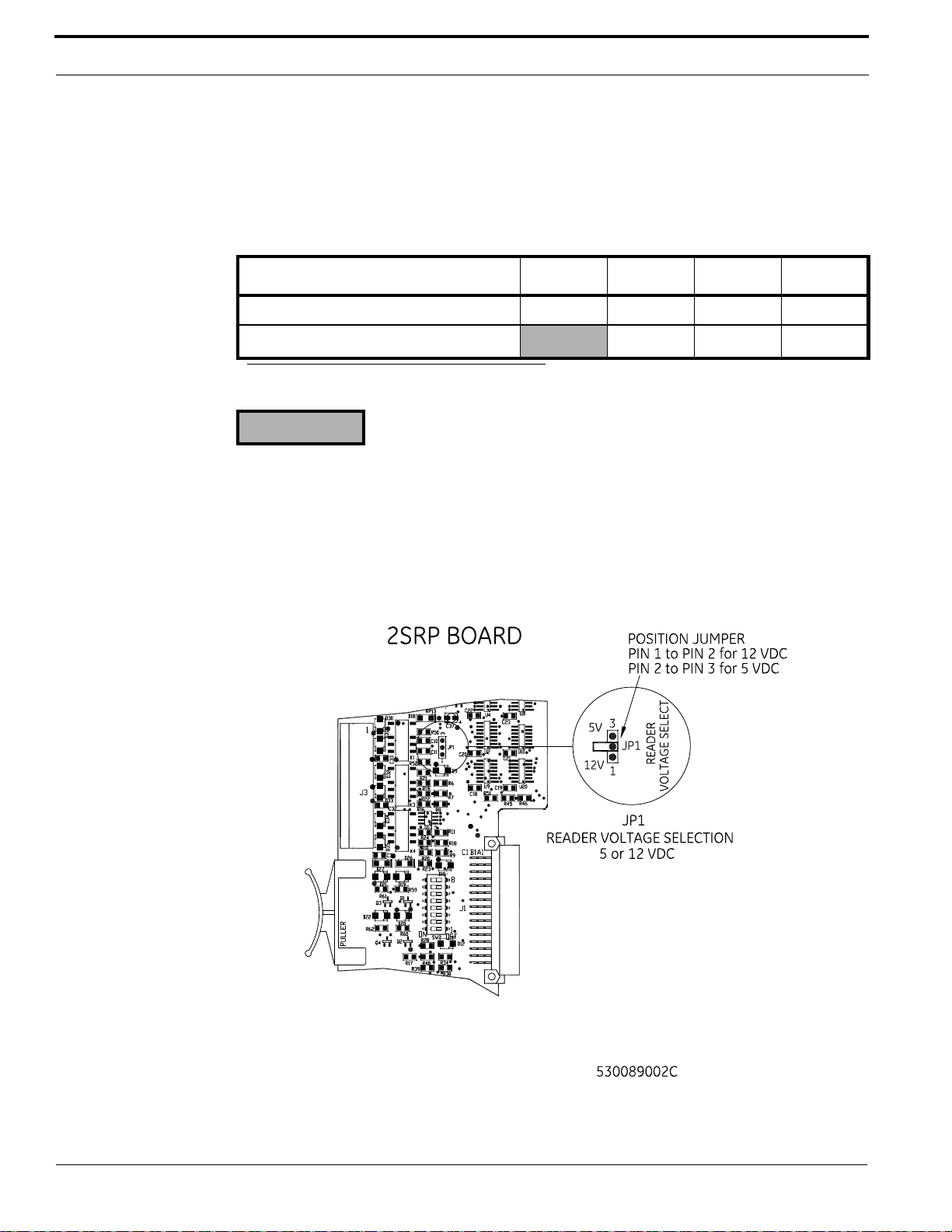
Reader Type SW4-5 SW4-6 SW4-7 SW4-8
Standard Readers ON ON ON ON
Special Readers (single-color LEDs)
a. For special readers, refer to figure Wiring 2SRP to Single Color LED Reader on page 58.
= OFF
a
ON ON ON
Setting Reader Voltage
Select the proper reader voltage by placing the jumper on JP1. Refer to the figure below for details.
Both reader ports are set to the selected voltage.
Setting 2SRP Reader Voltage
52 M3000 Installation Guide
Page 53
2SRP Board
Installing Resistor Packs
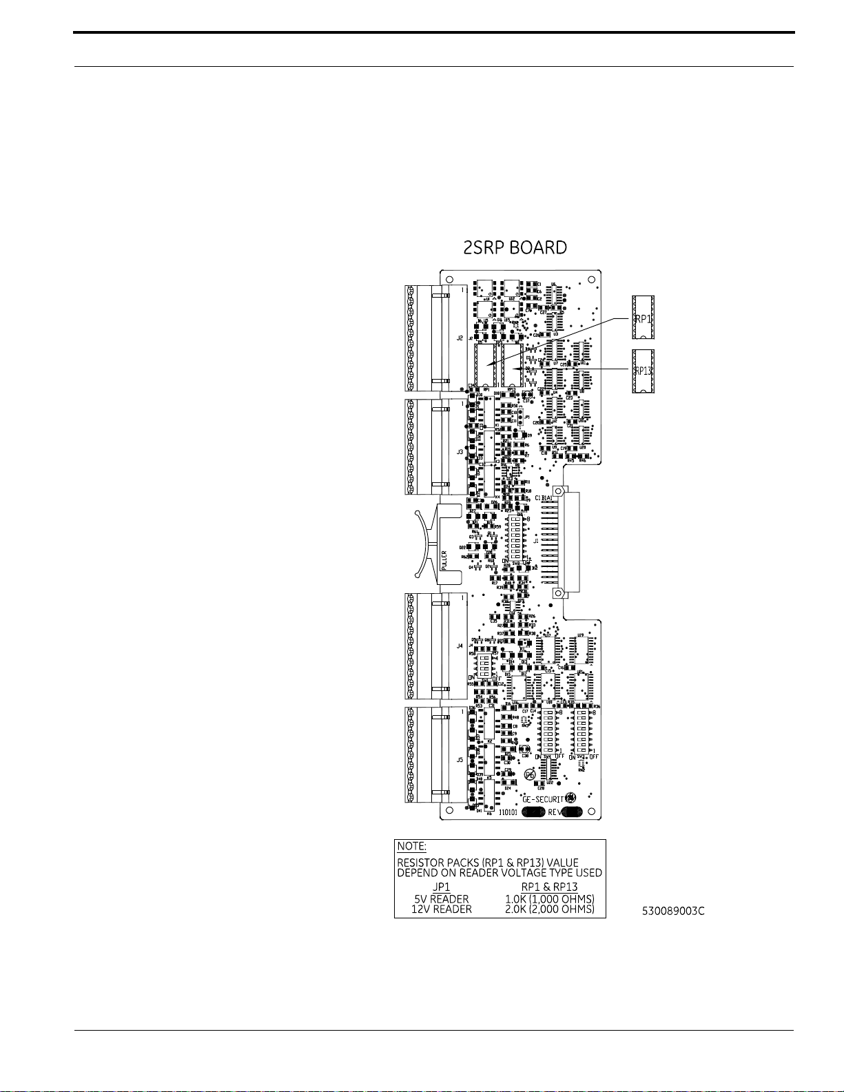
Insert proper resistor packs in RP1 and RP13. Be sure you insert the correct resistor pack for the
reader voltage selected. Both resistor packs must be the same since the voltage for both readers must
be the same. Refer to the figure below for details.
Installing 2SRP Resistor Packs
Wiring Readers
If wiring a 12 V reader that uses 5 V data lines, note the following conditions before continuing:
M3000 Installation Guide 53
Page 54
Reader Processing Boards
• Set the reader voltage (JP1) to 5 V.
• Wire the Reader power lead to the Power output port (J6) on the Power/Communications board
instead of to the 2SRP board.
To wire a 12 V reader:
1. Mount the reader. Refer to the manual that came with your reader for specific mounting
instructions.
2. Run cable from the reader to the controller. Bring each reader cable through the appropriate
knockout hole in the controller enclosure. Allow some slack wire for servicing the cables and for
plugging cable into an adjacent slot for troubleshooting.
3. Remove 8 inches (20.32 cm) of insulating material from the cable. Unwrap shielding and tie all
shields together. Connect the communications cable shield to the ground stud adjacent to the
cable entrance knockout of the cabinet enclosure. For more details, refer to figure Typical
Installation Using Shielded Cable/drain Wire - Outside and Inside the Enclosure on page 20.
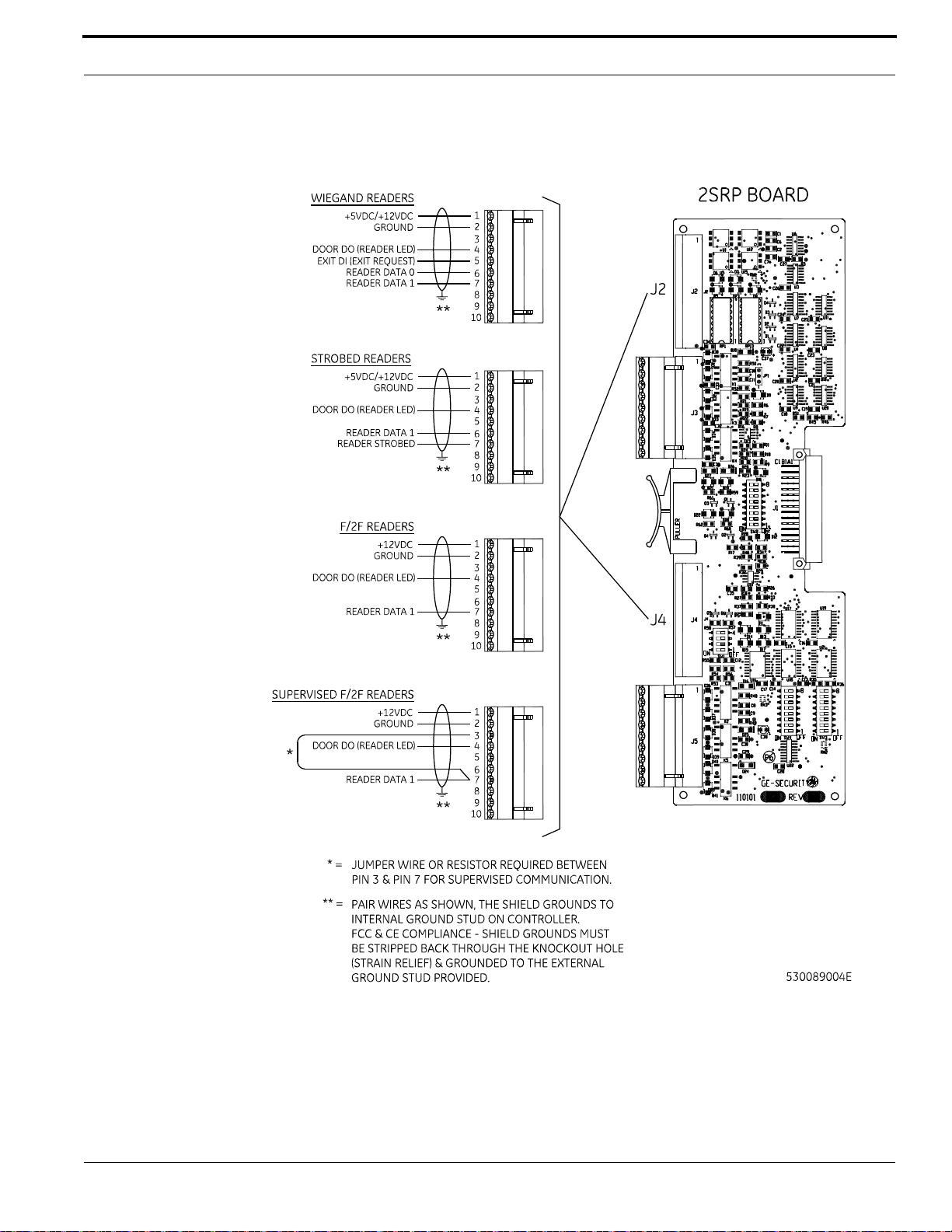
4. Place the appropriate wires to the appropriate screw terminal on the 2SRP reader board. Refer to
the reader wiring diagrams in this section. Pairing of cables is very important.
Note: The 2SRP board has built-in pull-up resistors. Do not install any external pull-up
resistors.
5. Label each cable end with the Controller Address Number/Device or Reader Number.
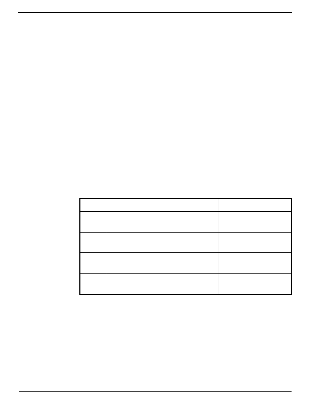
Recommended Pairing of Reader Wires - Typical Reader Cable (Use Belden
8725 twisted shielded pair or equivalent)
Pin Signal Name Typical Wire Color
1 +5V DC or +12V DC Reader Power Red
6
2 Ground (-) Green
7 Reader Data 1 White
4 Door DO (Reader LED) White/Black
8
3 Spare White/Green
9
a. Reader Data 0, Supervised Door DI, Supervised Door DI Return, and Supervised Exit Request DI Return
can be replaced or interchanged as needed.
Reader Data 0
Supervised Door DI (Alarm input)
Supervised Door DI Return
a
a
a
Black
White/Red
White/Yellow
54 M3000 Installation Guide
Page 55
2SRP Board
2SRP Supervised Reader Connector Points
M3000 Installation Guide 55
Page 56
Reader Processing Boards
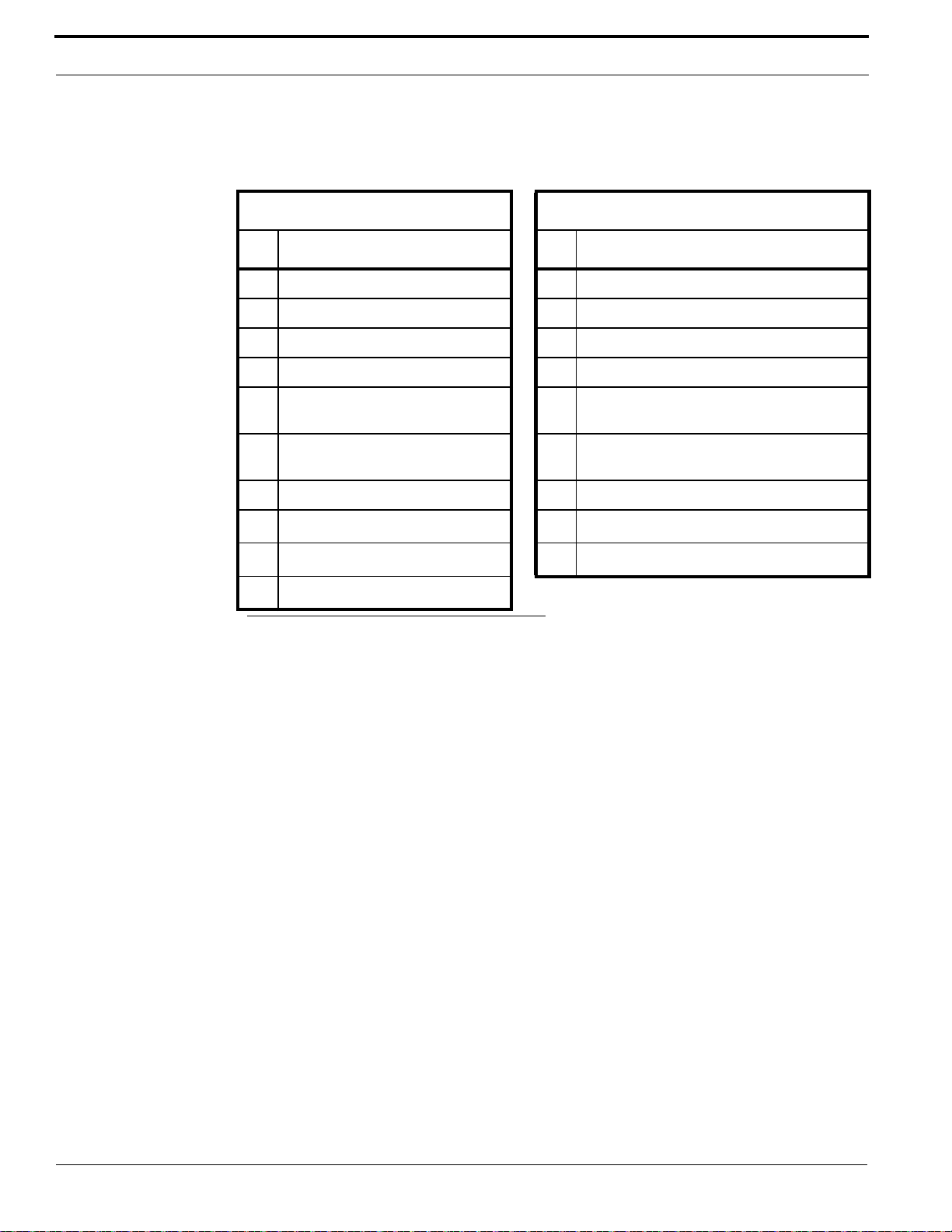
2SRP Connector Pinouts
J2/J4 Reader Connector Pinouts J3/J5 Relay Connector Pinouts
Pin Signal Name Pin Relay
1 +5 VDC/+12 VDC 1 Door Strike Relay – Normally Closed (NC)
2 Ground 2 Door Strike Relay – Common (Com)
3 Display DO 3 Door Strike Relay – Normally Open (NO)
4 Door DO (Reader LED) 4 Auxiliary Output Relay – Common (Com)
5
Supervised Exit DI (Exit Request)
a
5 Auxiliary Output Relay – Normally Closed
(NC)
6 Reader Data 0 6 Auxiliary Output Relay – Normally Open
(NO)
7 Reader Data 1 7 Alarm Shunt Relay – Common (Com)
8
Supervised Door DI (Alarm Point)
9
Supervised Door DI Return
10
Supervised Exit DI Return
a
a
a
8 Alarm Shunt Relay – Normally Closed (NC)
9 Alarm Shunt Relay – Normally Open (NO)
a. Supervised Exit DI and supervised Door DI point must use end-of-line resistors and must be terminated at
the appropriate Return point (not to ground).
56 M3000 Installation Guide
Page 57
2SRP Board
Wiring 2SRP to Wiegand, F/2F, Strobed, and Supervised F/2F Reader
M3000 Installation Guide 57
Page 58
Reader Processing Boards
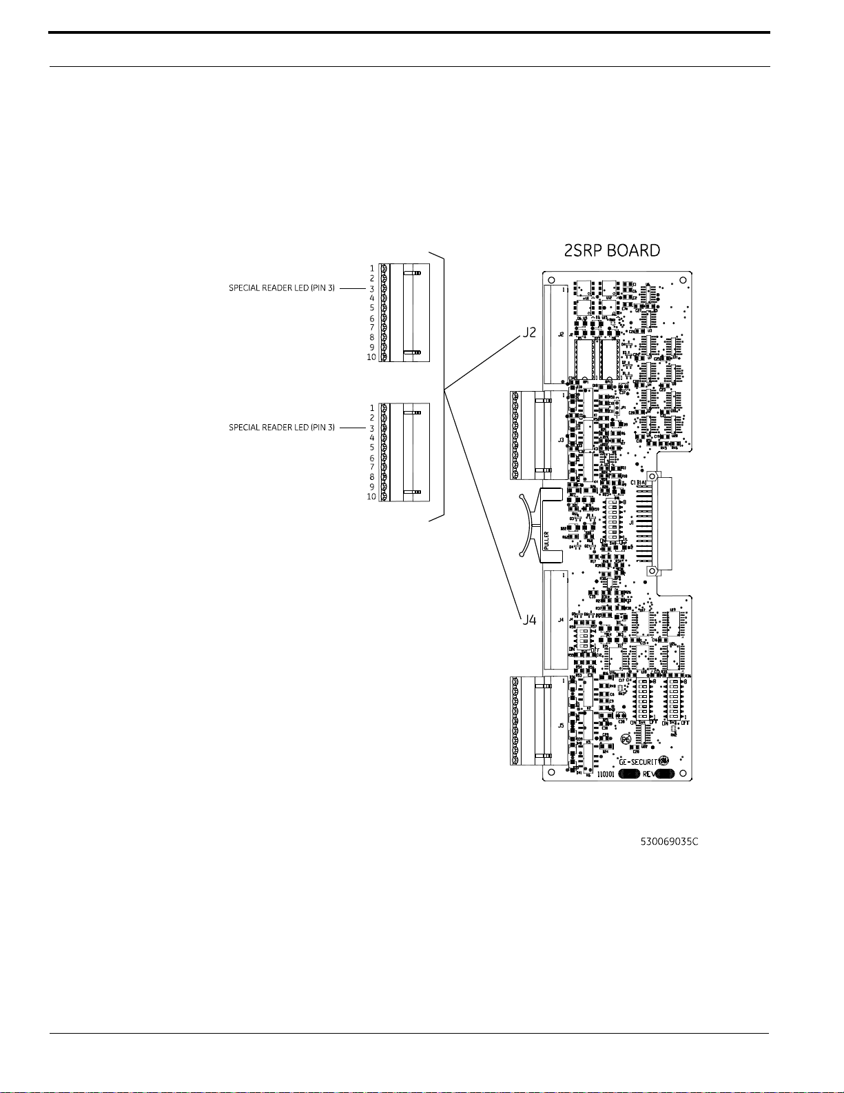
Special Readers with Single Color LEDs
The LEDs flash fast upon a valid access condition and turn off for 3 to 4 seconds upon an invalid
attempt. Refer to table Special Reader Types on page 52 for switch setting information. In this
configuration, the Alarm Shunt Relay is no longer available.
Wiring 2SRP to Single Color LED Reader
Wiring Digital Inputs
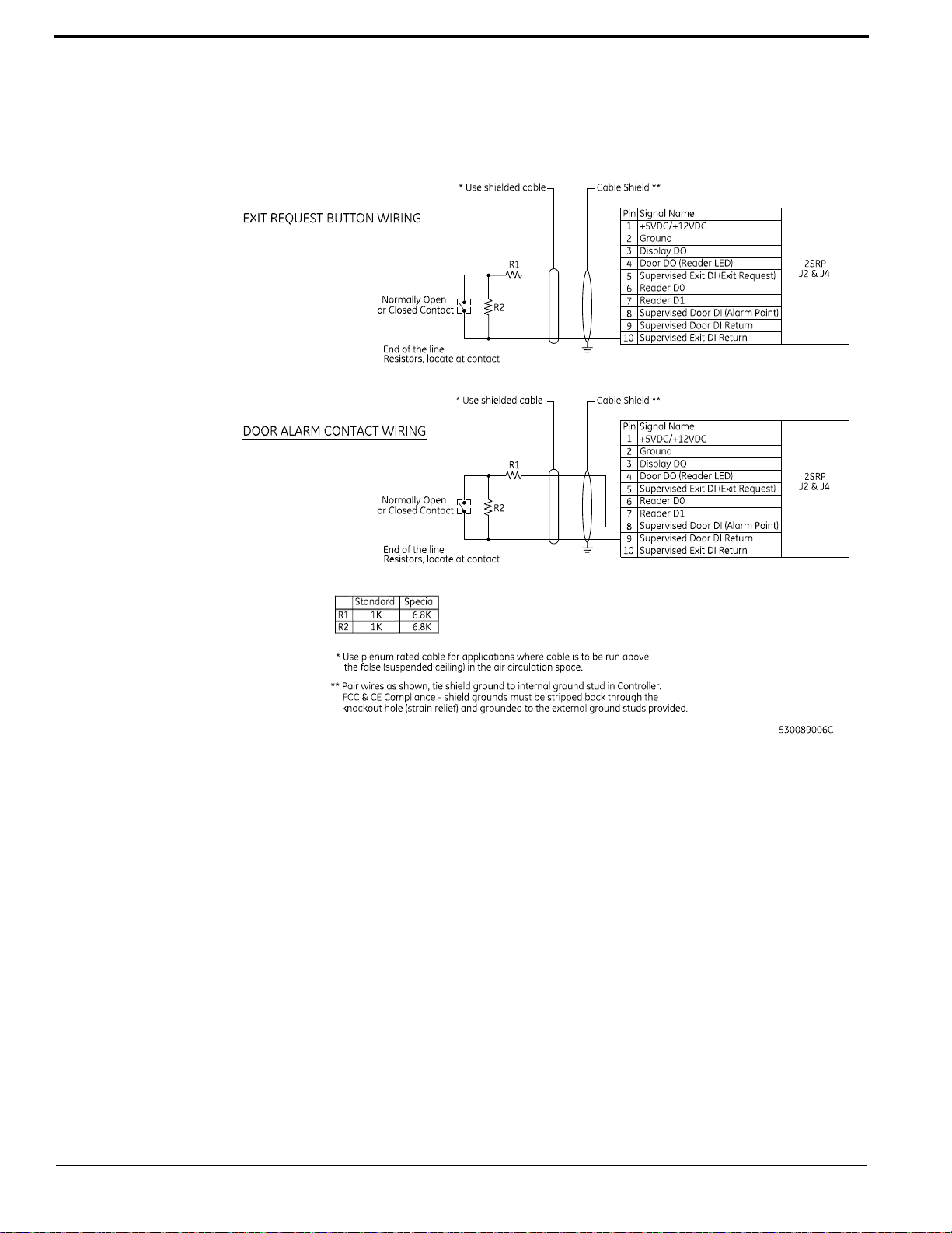
Each reader port has two (2) supervised digital inputs which are used for door status devices (door
contacts and exit request input). Since these digital inputs are supervised, they require end-of-line
resistors.
To wire a DI:
58 M3000 Installation Guide
Page 59

2SRP Board
1. Follow the installation specifications for the device. Mount the device according to the
manufacturer’s specifications. The alarm device (door contact) should have a dry contact which
can have a Normally Open or Normally Closed type switch. A Normally Closed contact is in its
normal or resting position when it is closed. For example, the contact is closed when the door is
closed. The opposite is true for a Normally Open contact. In this case, the contact is open when
the door is closed.
2. Select the appropriate digital input for each alarm input device.
3. Ground the shields of the cable at the M3000 enclosure grounding studs. Insulate the shield (with
tape or shrink tubing) at the DI device end to avoid electrical noise.
4. Install two (2) end-of-line resistors. Install each resistor as close to the door status contact as
possible.
5. We recommend the standard 1,000 (1K) ohm, 1/4 watt, 5% tolerance, high-quality end-of-line
resistors. If different resistor values are required, refer to Appendix B: Termination Resistance
Options.
Refer to figure Wiring 2SRP Door Alarm Contact and Exit Request on page 60 for the location of
the resistors.
Refer to table Supervised DI End-of-line Resistors on page 51 for the appropriate switch settings.
6. Wire the supervised door DI between pin 8 (Door DI) and pin 9 (Door DI Return). Wire the
supervised exit DI between pin 5 (Exit DI) and pin 10 (Exit DI Return). The contact can be
Normally Open or Normally Closed.
• WARNING! • The supervision capability will be impaired if the resistors are not wired
immediately adjacent to the door status contact.
7. Insulate resistors with tape or heat shrink tubing.
8. Document how you wired the alarm input devices. Future expansion of the system and its
maintenance depend upon accurate documentation.
M3000 Installation Guide 59
Page 60
Reader Processing Boards
Wiring 2SRP Door Alarm Contact and Exit Request
Wiring Door Strikes
One (1) reader LED (door DO) and one (1) door DO relay are dedicated to each reader port. The door
DO is used for the LED on the reader or an external door relay.
To wire a door strike:
1. Install the door strike (2 A @ 30 VDC or 0.50 A @ 120 VAC maximum) as required.
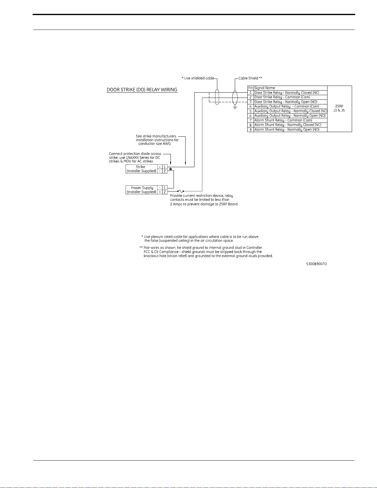
2. Wire the door strike to the door DO (internal) relay. Normally open or Normally Closed dry
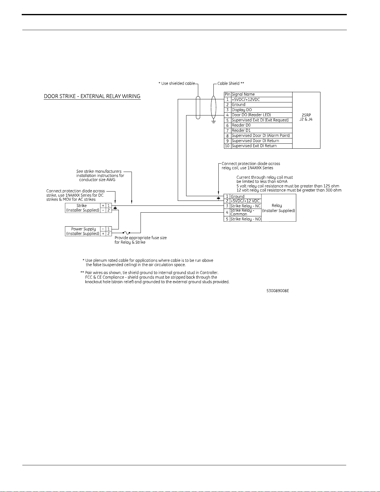
contacts are available (pin 1 = Normally Closed, pin 2 = Common, pin 3 = Normally Open). Use
pin 1 (+5/+12 VDC) and pin 4 (Reader LED) for wiring the external relay. Refer to figure Wiring
2SRP Door Strike - Internal Relay on page 61 and figure Wiring 2SRP Door Strike - External
Relay on page 62.
3. Install a protection diode. Use 1N4002, 1N4003, or 1N4004 diodes for DC door strikes and
Metal Oxide Varistors (MOV) for AC door strikes.
Note: A protection diode or MOV is required at each electronic door lock.
60 M3000 Installation Guide
Page 61
2SRP Board
Wiring 2SRP Door Strike - Internal Relay
M3000 Installation Guide 61
Page 62
Reader Processing Boards
Wiring 2SRP Door Strike - External Relay
Wiring Auxiliary DO Relays
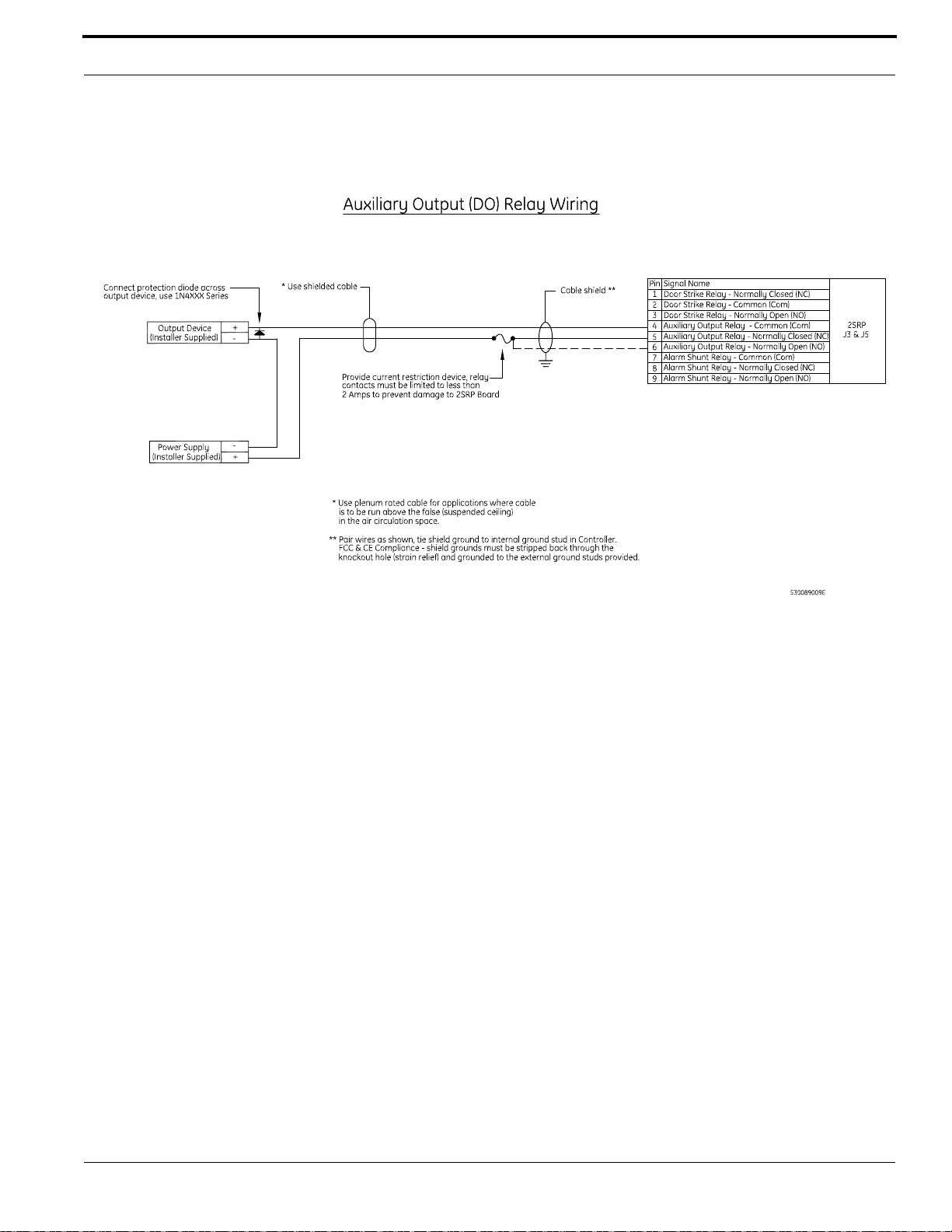
One (1) auxiliary DO relay per reader port can be defined by the user. The auxiliary DO relay is used
for an auxiliary output device.
To wire an auxiliary DO relay:
1. Install the auxiliary output device (maximum 2 A @ 30 VDC or 0.50 A @ 120 VAC) as required.
2. Wire the output device to the auxiliary DO relay. The auxiliary DO relay has either a Normally
Open or Normally Closed dry contact available (pin 4 = Common, pin 5 = Normally Closed,
pin 6 = Normally Open).
62 M3000 Installation Guide
Page 63
2SRP Board
Wiring 2SRP Auxiliary DO Relay
Wiring Alarm Shunt Relays
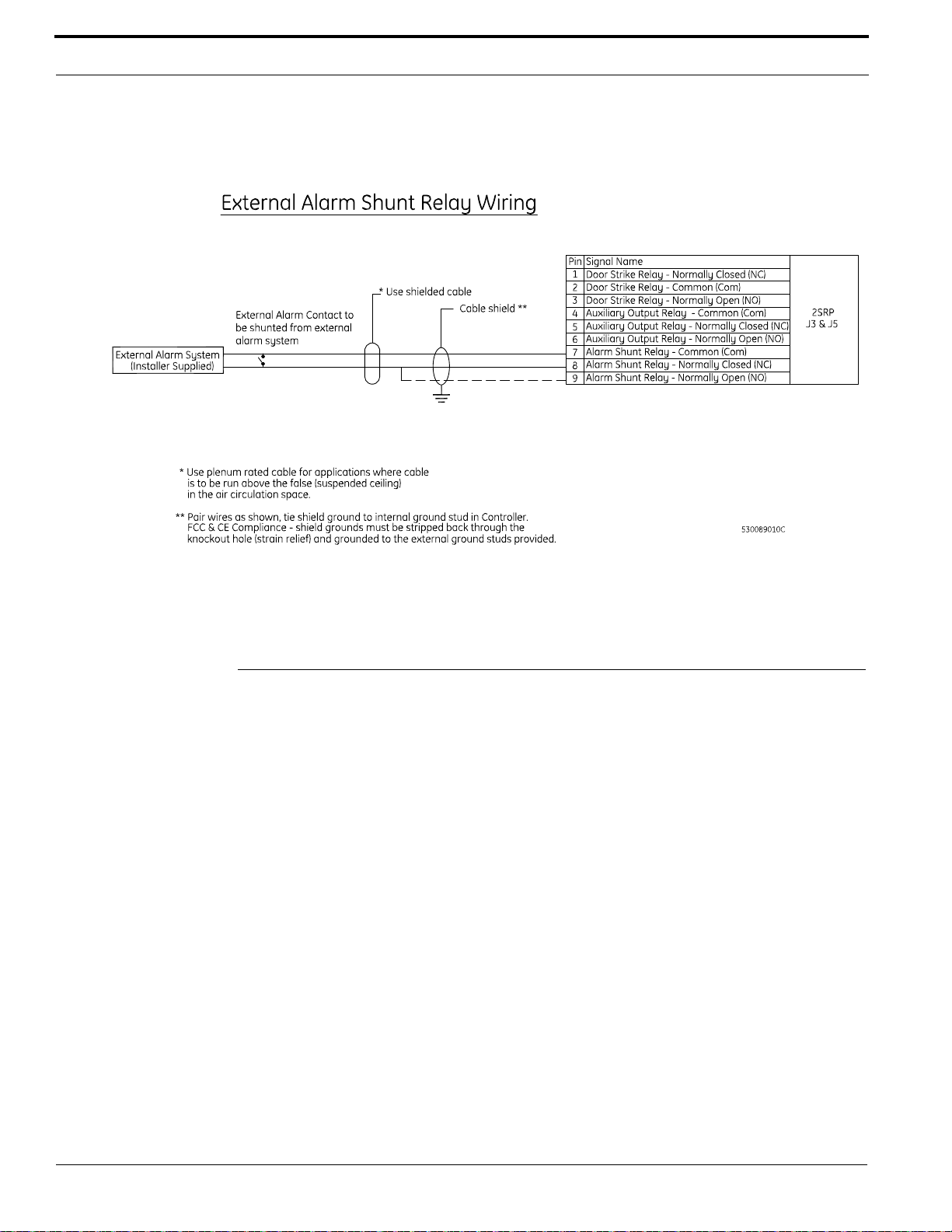
One (1) alarm shunt relay is available per reader port. The alarm shunt relay is used to shunt (disable)
an external alarm system contact (e.g., burglar alarm) on a valid read or exit push button request.
To wire an alarm shunt relay:
1. Install the alarm shunt (2 A @ 30 VDC or 0.50 A @ 120 VAC) as required.
2. Wire external alarm system to the alarm shunt relay. The relay has either a Normally Open or
Normally Closed dry contact available (pin 7 = Common, pin 8 = Normally Closed, pin 9 =
Normally Open).
Note: Single color LED readers do not support alarm shunt relays.
M3000 Installation Guide 63
Page 64
Reader Processing Boards
Wiring 2SRP External Alarm Shunt Relay
8RP Board
Each 8RP board provides:
• Eight (8) reader ports
• One (1) digital output (reader LED) per reader port
Please note the following:
• The 8RP board was redesigned to work with 12 V readers only. This version of the 8RP board
can be identified by the assembly number 110100001 with a revision of C or later.
• Each 8RP board is limited to only one type of reader technology: F/2F or Supervised F/2F.
• External pull-up resistors are not required for the 8RP board.
• No DI (alarm points) or exit DIs are available on the 8RP board. Therefore, use of supervised
readers is recommended since these points are available on the reader.
• If keypad readers are needed, use Supervised F/2F keypad readers.
– If non-supervised F/2F keypad readers are used, Wiegand Interface Units (WIU-2/WIU-4)
are required.
• The 8RP board provides one (1) digital output (reader LED) per reader port, 0.10 amps @
12 VDC maximum per output point.
64 M3000 Installation Guide
Page 65
8RP Board
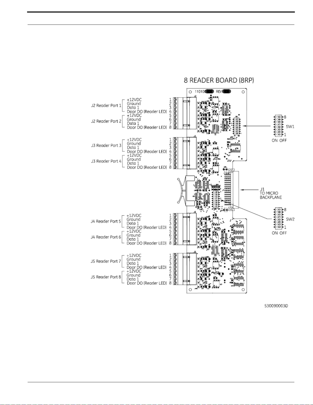
Board Layout
8RP Board Layout
M3000 Installation Guide 65
Page 66
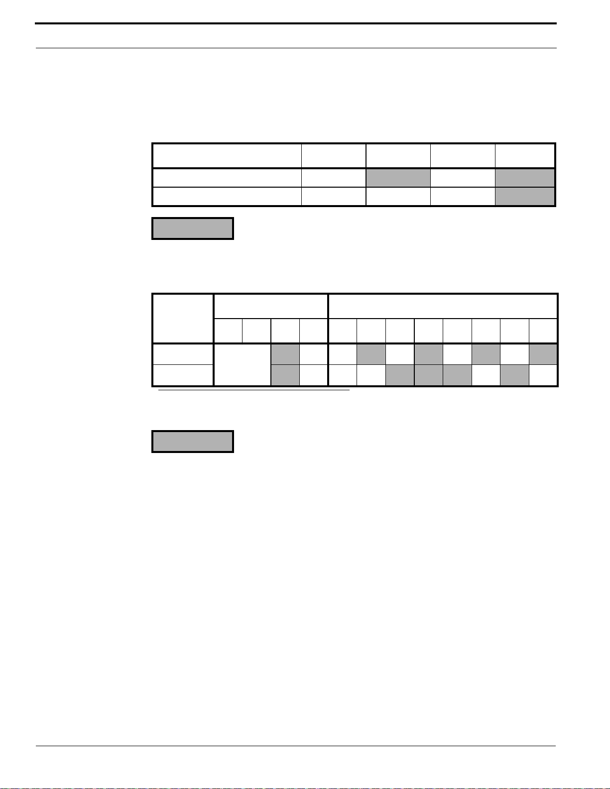
Reader Processing Boards
Setting the DIP Switches
Set the DIP switches as described in the table below before installing and wiring the 8RP board.
Reader Technology
Reader Technology SW 1-1 SW 1-2 SW 1-3 SW 1-4
Magstripe - Supervised F/2F ON
Magstripe - F/2F ON ON ON
= OFF
8RP Board Address Settings
SW 1- SW 2-
Board Type
Board 1
Board 2
= OFF
a
b
a. The first eight (8) readers out of 16.
b. The second eight (8) readers out of 16.
567812345678
Does not
apply.
ON ON ON ON ON
ON ON ON ON ON
ON
Powering Two 8RP Boards
To ensure proper function when using two 8RP Boards in the M3000 controller, the second 8RP
Board should be wired directly to the Power Communication board as shown in the figure below.
66 M3000 Installation Guide
Page 67
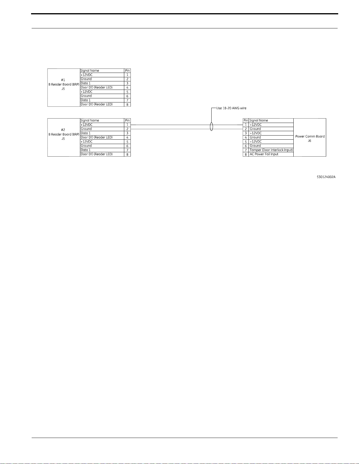
8RP Board
Powering Two 8RP Boards
To wire each 8RP board:
1. Connect an 18- or 20- gauge wire from Power/Communications board J6 Pin 1 (+12 VDC) to
8RP board J5 Pin 1 (+12 VDC)
2. Connect an 18- or 20- gauge wire from Power/Communications board J6 Pin 2 (GND) to 8RP
board J5 Pin 2 (GND)
3. Connect the power supply (5 A or higher required) to Power/Communications board J6 Pin 3
(+12 VDC) and Pin 4 (GND).
Wiring Readers
To wire a reader:
1. Mount the reader. Refer to the manual that came with your reader for specific mounting
instructions.
2. Run cable from the reader to the controller. Bring each reader cable through the appropriate
knockout hole in the controller cabinet. Allow some slack wire for servicing the cables and for
plugging the cable into an adjacent slot for troubleshooting.
3. Remove 8 inches (20.32 cm) of insulating material from the cable. Unwrap shielding and tie all
shields together. Connect the communications cable shield to the ground nut adjacent to the cable
entrance knockout of the cabinet enclosure. For more details, refer to figure Typical Installation
Using Shielded Cable/drain Wire - Outside and Inside the Enclosure on page 20.
4. Place the appropriate wires to the appropriate screw terminal on the 8RP reader board. Refer to
the reader wiring diagrams in this section. Pairing of cables is very important.
Caution: The 8RP board has built-in pull-up resistors. Do not install the external
pull-up resistors supplied with Proximity Readers.
5. Label each cable end with Controller Address Number/Device or Reader Number.
W e recommend using 20-AWG shielded cable for wiring reader DOs and DIs. Use plenum-rated
cable for applications where cable is to be run above the false (suspended) ceiling in the air
circulation space.
The following cable types are recommended:
M3000 Installation Guide 67
Page 68
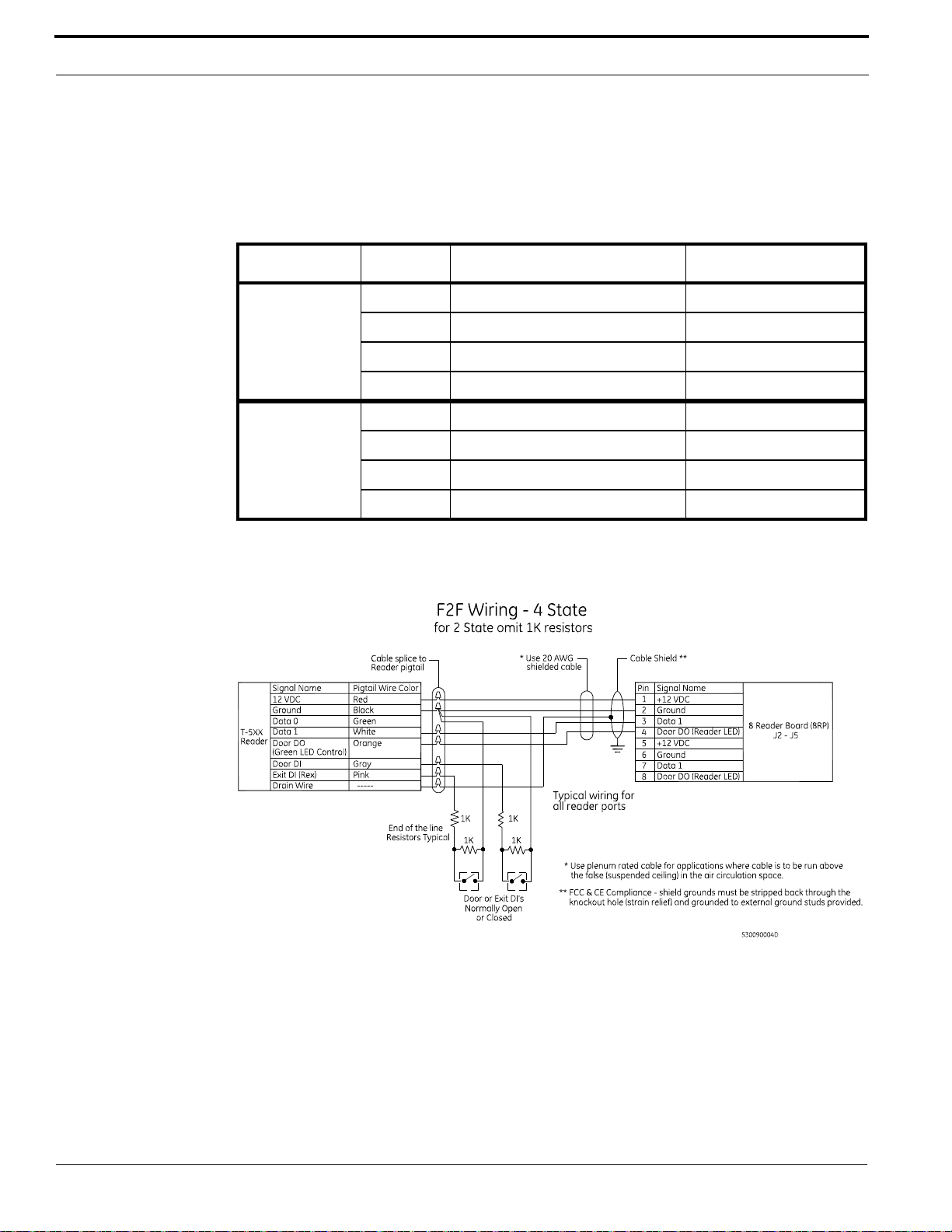
Reader Processing Boards
• Alpha Xtra Guard1® foil shield cable, non-plenum rated, and
• Belden security and alarm cable (commercial applications shielded), plenum-rated.
J2/J3/J4/J5 Reader Connector Pinouts and Recommended Pairing
Reader Port Pin Signal Name Typical Wire Color
1/3/5/7 1 +12 VDC Red
2 Ground Black
3 Reader Data 1 White
4 Door DO (Reader LED) Orange
2/4/6/8 5 +12 VDC Red
6 Ground Black
7 Reader Data 1 White
8 Door DO (Reader LED) Orange
Wiring 8RP to F/2F or Supervised F/2F Readers
Wiring Door Strikes
One (1) reader LED (door DO) is dedicated to each reader. The reader LED (door DO) is used for the
reader LED and/or for an external door strike relay.
To wire a door strike:
1. Install the door strike as required.
68 M3000 Installation Guide
Page 69
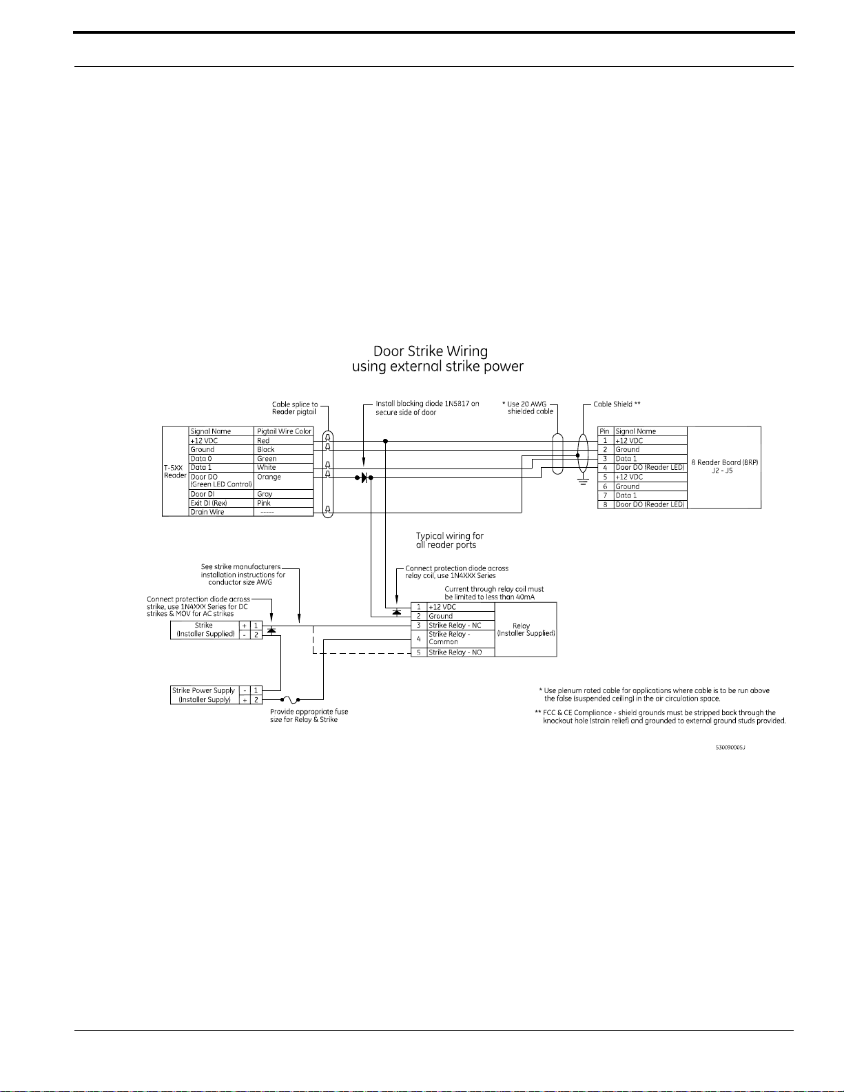
8RP Board
2. Wire the door strike to the external door strike relay. The door strike relay is connected to
+12 VDC (pin 1 and/or pin 5) and door DO (pin 4 and/or pin 8).
3. Install a protection diode across the relay and the door strike. Use 1N4002, 1N4003, 1N4004 or
equivalent diodes for DC door strikes and Metal Oxide Varistors (MOV) for AC door strikes.
Note: Protection diode or MOV and blocking diode required at all electronic door locks.
4. Install a blocking diode on the door DO (Reader LED) line between the reader and the door
strike relay. Use 1N5817 (included with reader). The diode must be installed on the secure side of
the door to be UL-compliant.
Wiring 8RP Door Strike - External Relay
M3000 Installation Guide 69
Page 70

Reader Processing Boards
70 M3000 Installation Guide
Page 71

CHAPTER 6 Optional DI and DO Boards
The M3000 controller supports the following DI and DO boards:
• 20 Digital Input (20DI) board (page 71)
• 16 Digital Output (16DO) board (page 74),
• 16 Digital Output with Relays (16DOR) board (page 74).
Although the M3000 enclosure holds up to five (5) option boards, the specific number of DI and DO
boards supported by the different host software systems varies. OnGuard supports a maximum of 4
DI or 4 DO/DOR boards.
20DI Board
The 20DI board provides 20 supervised digital input (alarm) points. Supervised DIs have end-of-line
resistors on the contacts which enable the controller to detect line shorts and breaks in addition to the
open and closed contact conditions.
Please note the following:
• The maximum distance allowed between the M3000 and the alarm input device is 1,000 feet
(304.8 m).
• The recommended cable wire is a two-conductor, 22-AWG shielded, stranded cable.
M3000 Installation Guide 71
Page 72
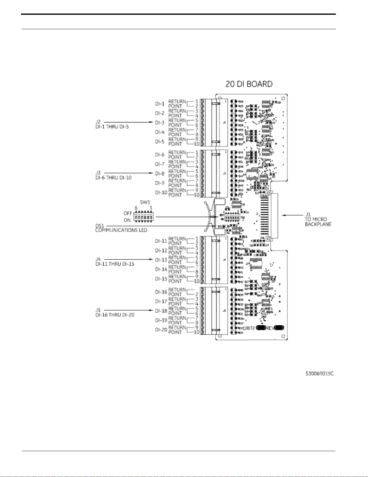
Optional DI and DO Boards
20DI Board Layout
20DI Board Layout
72 M3000 Installation Guide
Page 73
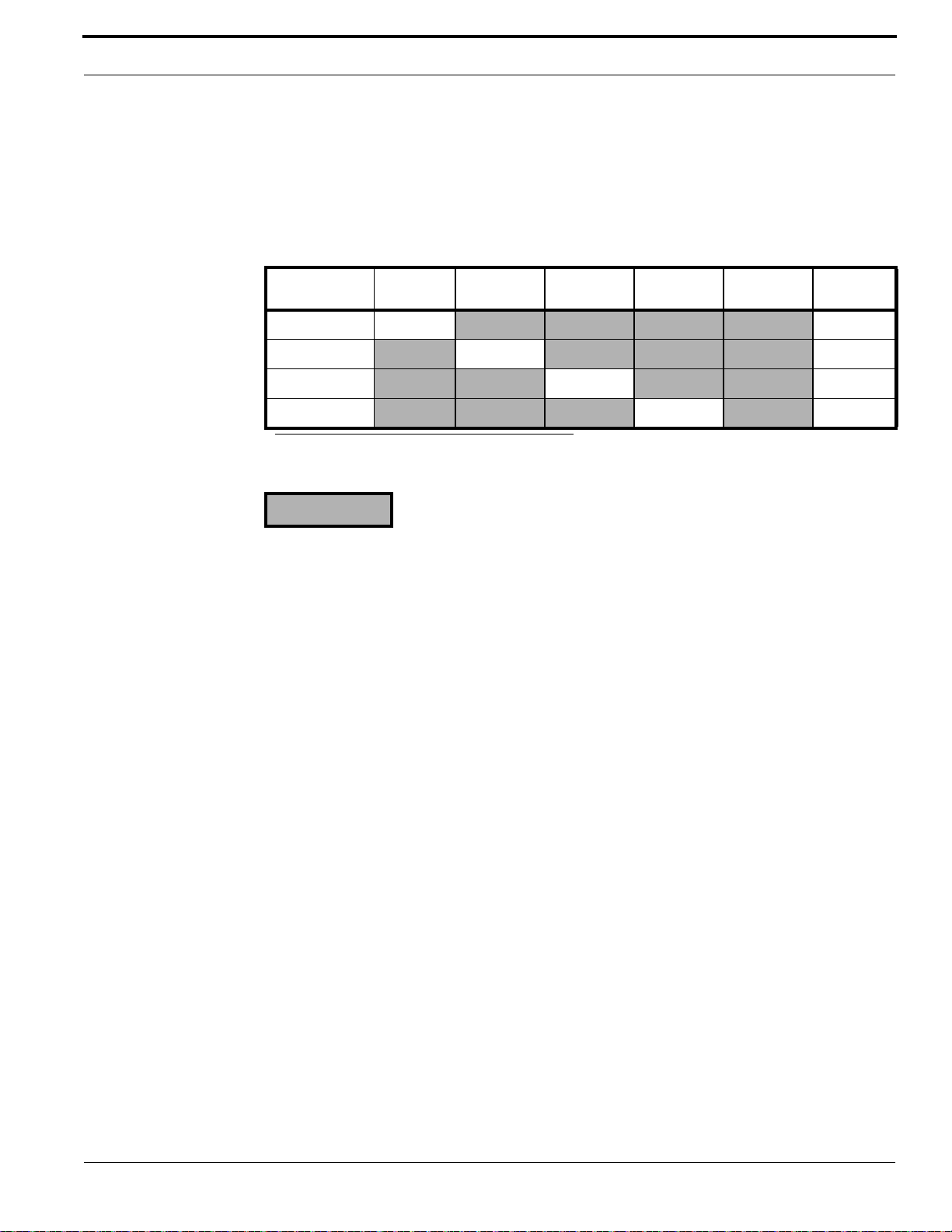
20DI Board
Setting the DIP Switches
Set the DIP switches on the 20DI board before installing it and wiring the alarm input devices. The
20DI PCB board should be at Revision G or later. (The revision level can be found on the underside
of the circuit board in the lower right corner.)
20DI Board Addressing
a
Board SW1-1 SW1-2 SW1-3 SW1-4
SW1-5 SW1-6
Board 1 ON
Board 2
Board 3
Board 4
a. ON for M5/E, M5/2, M5/P;
OFF for M5/PX, M5/PXN, M5/PXNPlus, and M3000.
= OFF
ON (1)
ON (1)
ON (1)
(1)
Wiring Digital Input Devices
To wire a digital input device:
1. Follow the installation specifications for the DI device. Mount the device according to the
manufacturer’s specifications. The alarm device (door contact) should have a dry contact which
can have a Normally Open or Normally Closed type switch. A Normally Closed contact is in its
normal position when it is closed. The opposite is true for a Normally Open contact.
2. Select the appropriate digital input for each alarm input device.
3. Ground the shields of the cable at the M3000 enclosure grounding studs. Float the shield (with
tape or shrink tubing) at the DI device end to avoid electrical noise.
4. Install two (2) end-of-line resistors. We recommend high quality, 1,000 (1K) ohm, 1/4 watt, 5%
tolerance end-of-line resistors. Install each resistor as close to the door status contact as possible.
If different resistors are required, refer to Appendix B: Termination Resistance Options.
• WARNING! • The supervision capability will be impaired if the resistors are not wired
immediately adjacent to the door status contact.
5. Insulate resistors with tape or heat shrink tubing.
6. Document how you wired the alarm input devices. Future expansion of the system and its
maintenance depend upon accurate documentation.
M3000 Installation Guide 73
Page 74
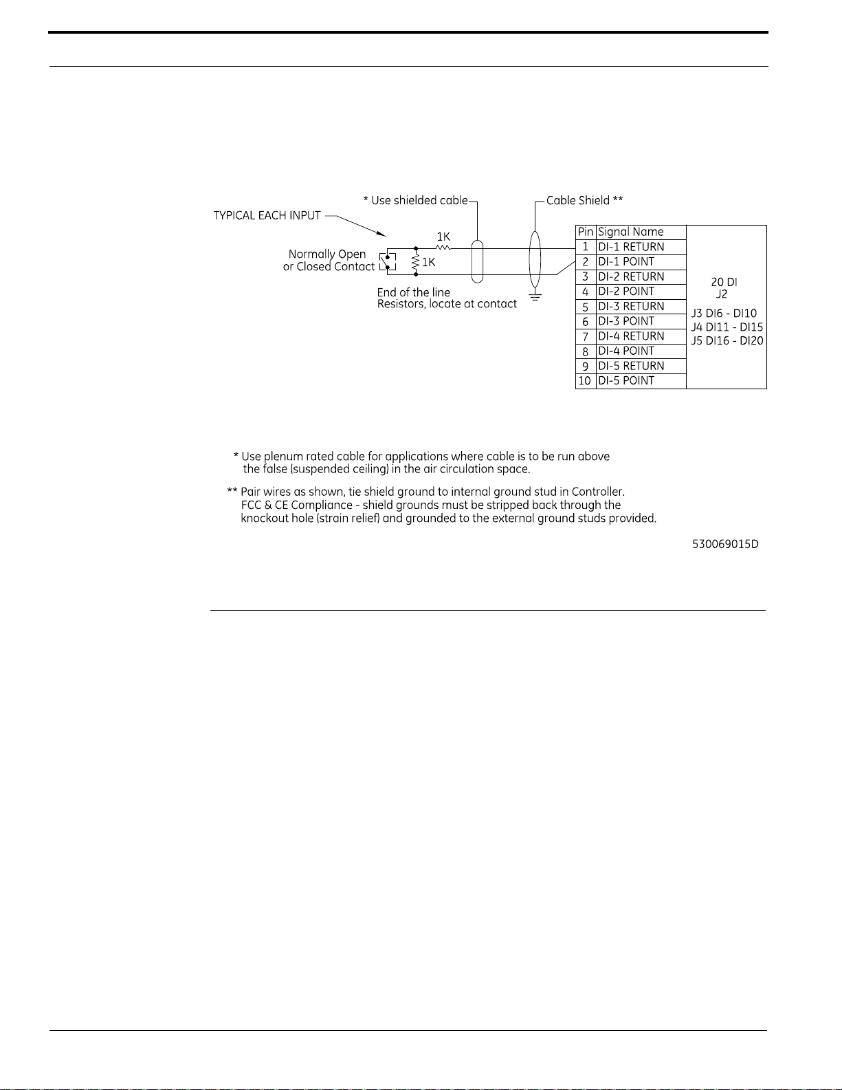
Optional DI and DO Boards
Wiring DI Point
16DO and 16DOR Boards
Two types of DO boards are available:
• the 16 Digital Output (16DO) board and
• the 16 Digital Output with Relays (16DOR) board.
The 16DO board provides 16 digital outputs rated at 100 mA @ 24 VDC maximum per output point.
The 16DOR board has 16 relay output points rated at 2 A @ 30 VDC or 0.50 A @ 120 VAC
maximum per output point. The first two relays on each J connector can be wired as Normally Open
or Normally Closed. The last two relays on each J connector are factory-set as Normally Open.
Please note the following:
• The maximum allowable distance between the M3000 16DO/16DOR board and the output
device is 1,000 feet (304.8 m).
• Two-conductor, 22-AWG shielded, stranded wire is recommended for the 16DO board.
• Two conductor 18 to 22-AWG shielded, stranded wire is recommended for the 16DOR board
depending on the cable distance, amperage (current draw), and voltage of the output device.
74 M3000 Installation Guide
Page 75
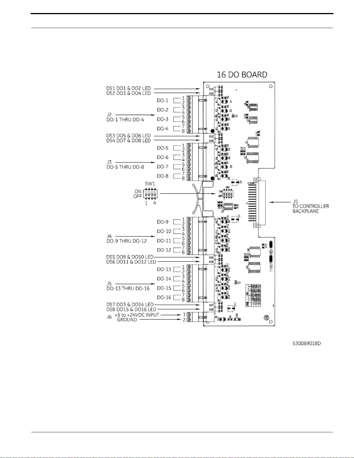
16DO and 16DOR Boards
16DO Board Layout
M3000 Installation Guide 75
Page 76
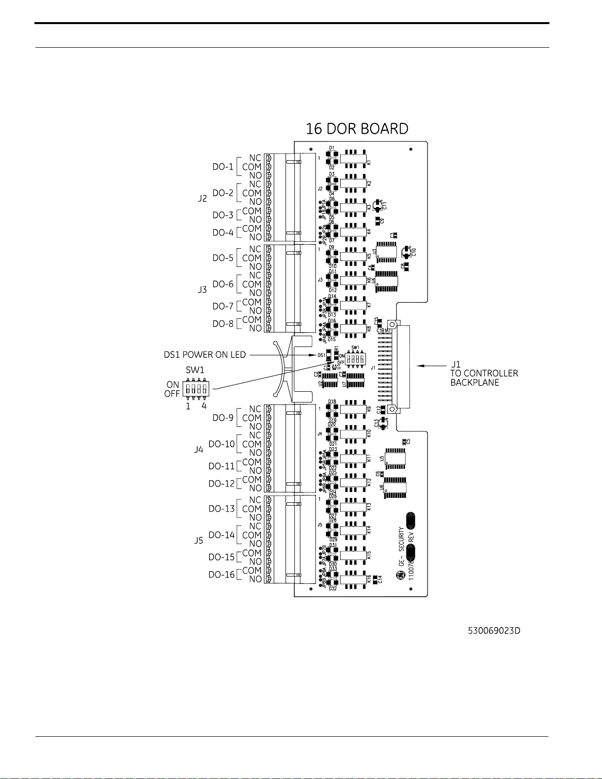
Optional DI and DO Boards
16DOR Board Layout
76 M3000 Installation Guide
Page 77
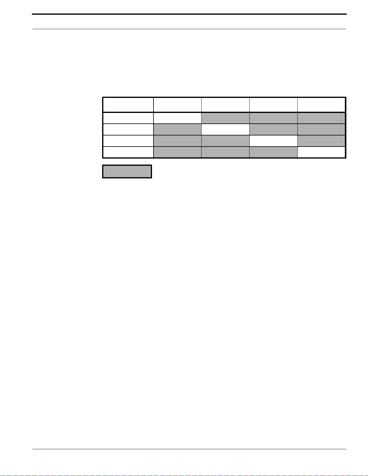
16DO and 16DOR Boards
Setting the DIP Switches
Set the DIP switches as described in the table below before installing the 16DO/DOR board and
wiring the digital output devices.
DO/DOR Board Addressing
Board Number SW1-1 SW1-2 SW1-3 SW1-4
1ON
2 ON
3 ON
4 ON
= OFF
Wiring Digital Output Devices
To wire a digital output (DO) device:
1. Mount the digital output device according to the manufacturer’s specifications.
2. Complete the wiring. If the DO is used to energize a relay, install a diode in parallel with the
relay coil to absorb transients when the relay is de-energized. A transient protection diode (user
supplied) is necessary on the 16DO board.
3. Connect a 5 to 24 VDC power supply to port J6. The voltage needed depends on the relay
requirements of the DO points. Pins 1, 3, 5, and 7 on ports J2, J3, J4, and J5 get their DC voltage
from pin 1 on J6.
M3000 Installation Guide 77
Page 78
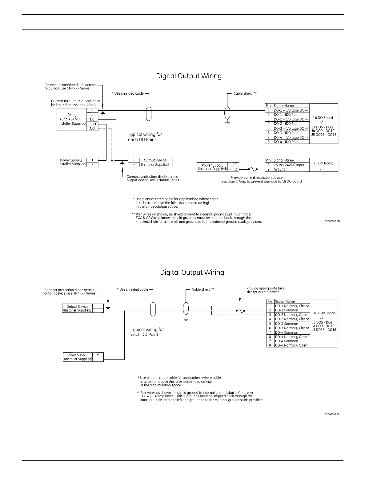
Optional DI and DO Boards
Wiring Output Device to 16DO Board
Wiring Output Device to 16DOR Board
78 M3000 Installation Guide
Page 79

CHAPTER 7 Pre-Power Up Testing
Follow the steps below before powering up the controller.
1. Measure the AC power supplied to the power supply (110 VAC or 220 VAC, depending on the
power supply installed). The power supply must have a dedicated circuit breaker. Do not plug
into an outlet that is controlled by an on/off switch.
2. Test the reader power wiring to determine if a short circuit exists. Unplug each reader connector
and measure, from the reader connector going out to the readers between pin 1 to chassis and
pin 1 to pin 2, with an ohmmeter.
Result: A measurement of less than 100 ohms indicates a short circuit. Correct this condition
before powering up.
3. If a 16DO board is installed, check for a short circuit. Unplug each connector and measure from
chassis ground to all pins on the DO connector.
Result: A measurement of less than 100 ohms indicates a short circuit. Trace out the wiring to
locate the short circuit.
4. Reconnect all connectors.
5. Disconnect power input connector J6 on the Power/Communications board.
6. Use a voltmeter to measure input voltage across J6. Pin 3 = +, pin 4 = Ground.
Result: If the meter reads -12 to -15 VDC, the wires are reversed.
Solution: Reverse the wires on pins 3 and 4 so pin 3 is the + voltage. The meter should read +12
to +15 VDC.
7. Reconnect the J6 connector.
Once you have completed these steps, power up the M3000.
M3000 Installation Guide 79
Page 80

Pre-Power Up Testing
80 M3000 Installation Guide
Page 81

CHAPTER 8 Controller Firmware Tools
Integrated Configuration Tool (ICT)
The ICT is a browser-based utility used to configure the PXNplus CPU board, update the firmware,
and view the controller information reports.
Software and Hardware Requirements
One of the following Internet browsers:
• A supported Internet browser.
Refer to the OnGuard Release Notes for supported browsers and versions.
• One of the following setups:
– Cat 5 cable with network hub
(refer to figure Connecting Through Network Hub on page 82).
– Cat 5 cable for direct connection to a controller.
M3000 Installation Guide 81
Page 82
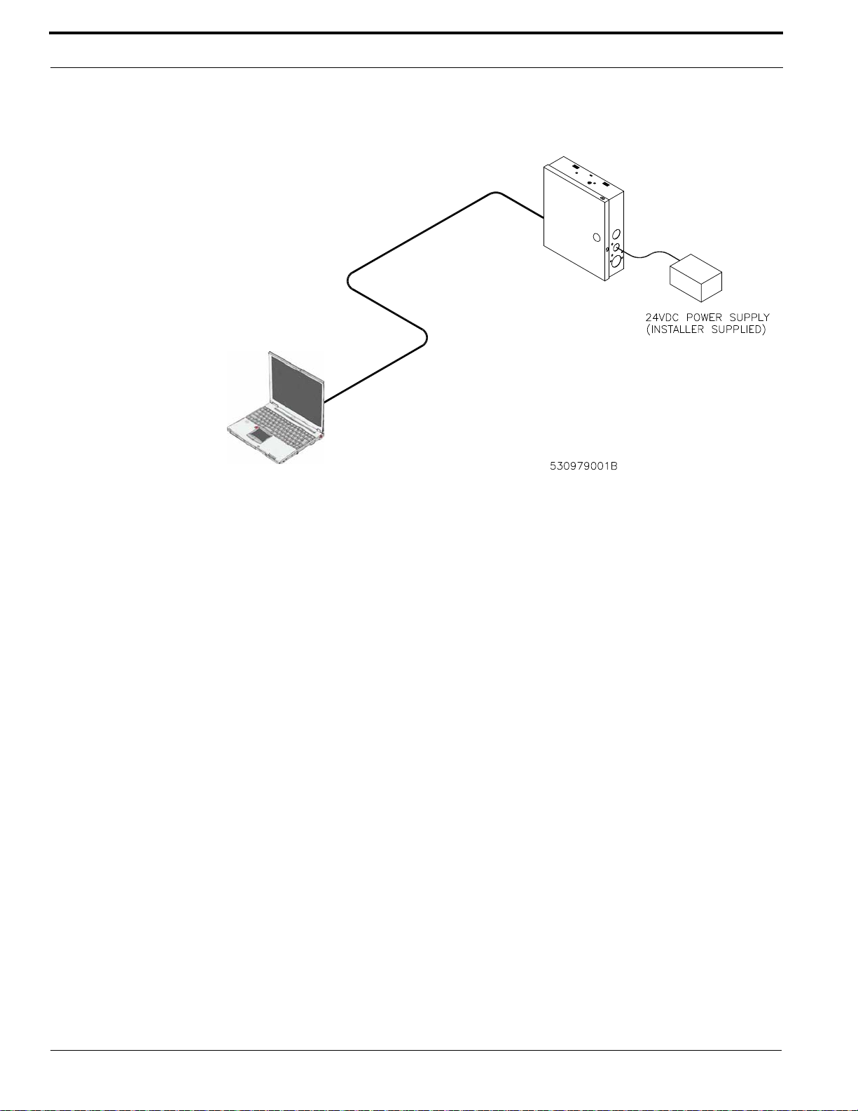
Controller Firmware Tools
Connecting Through Network Hub
Answer these questions before continuing:
• Is there a firewall on the computer you are using to access the Integrated Configuration
Tool? If yes, disable the firewall in order to use the Integrated Configuration Tool.
• Is your network using a proxy? If yes, disable the proxy or bypass it.
Complete the Configuration Checklist for the Integrated Configuration Tool on page 91 for each
controller. Then return to this section and proceed with the initial configuration, as described next.
Initial Configuration
By default, the controller’s IP address is 192.168.6.6. To have your computer communicate with
the controller, you must set your computer IP address to 192.168.6.5, or similar valid IP address
(192.168.6.x where x is any number between 1 and 254 except 6).
1. In Windows, open the Network and Sharing Center.
For more information, refer to “Using OnGuard in the Supported Operating Systems” in the
Installation Guide.
2. In the View your active networks section of the form, click the Local Ar ea Connection link.
Note: If you are not currently connected to a network, restore the connection before
continuing. Use the Windows Network Diagnostics tools, or contact your Network
Administrator for assistance.
3. In the Local Area Connection dialog box, click Properties.
4. In the Local Area Connection Properties dialog box, select either Internet Protocol Version 4
(TCP/IPv4) or Internet Protocol Version 6 (TCP/IPv6).
5. Click Properties.
• If Obtain an IPvx /Address Automatically is already checked, select Use the Following
IPvx Address, where x is the Internet Protocol Version you are using (4 or 6).
82 M3000 Installation Guide
Page 83

Integrated Configuration Tool (ICT)
• If the connection is static, write down the IP address and Subnet mask number. You will
need to reset your computer back to these numbers once the controller configuration is
complete.
6. Enter the IP address, 192.168.6.5, or a similar valid IP address (192.168.6.x where x is
any number between 1 and 254 except 6).
7. Change the Subnet Prefix Length value to 255.255.255.0. You do not need to change the
default gateway.
8. Click OK and Close until all open windows are closed.
9. Connect the computer to the RJ45 connector on the controller’s CPU board using a network hub
or standard Cat 5 cable.
10. If your controller is not yet powered up, power it up now.
11. Open an Internet browser window on your computer.
12. In the browser’s Address field, enter the default static IP address of the controller:
192.168.6.6
13. The Integrated Configuration Tool starts. At the password screen, enter your username and
password. The default is install, install. We recommend that you change this default.
Connecting and Starting the Tool
If this is the first time setting up this controller, you will need to follow special directions. Refer to
Initial Configuration on page 82. Otherwise, follow the steps below to start the Integrated
Configuration T ool (ICT).
To start the Integrated Configuration Tool:
1. Connect the computer to the RJ45 connector on the controller’s CPU board using a network hub
or standard Cat 5 cable.
2. Open an Internet browser window on your computer.
3. In the browser Address field, enter the IP address of the controller.
4. When the Integrated Configuration T ool starts, enter your username and password. The default is
install, install. We recommend that you change this default.
If you need to update the controller, refer to Upgrading the Controller Firmware on page 89.
Controller Setup Overview
To set up the controller, complete the following forms in the Integrated Configuration Tool (ICT):
• Controller Information Menu > Parameters Form: Set the controller’s host Port Number.
• Controller Parameters Menu > Primary Network Form: Set up static or dynamic IP addressing.
• Controller Parameters Menu > Secondary Network Form: This form is available if the controller
has a secondary Network Interface Card (NIC). Set up static or dynamic IP addressing.
Note: The ICT screens included in this section are examples only. The actual fields visible on
each form vary depending upon which configuration options you have selected.
Saving Configuration Changes
Before using the ICT, note the following details about saving your changes:
M3000 Installation Guide 83
Page 84
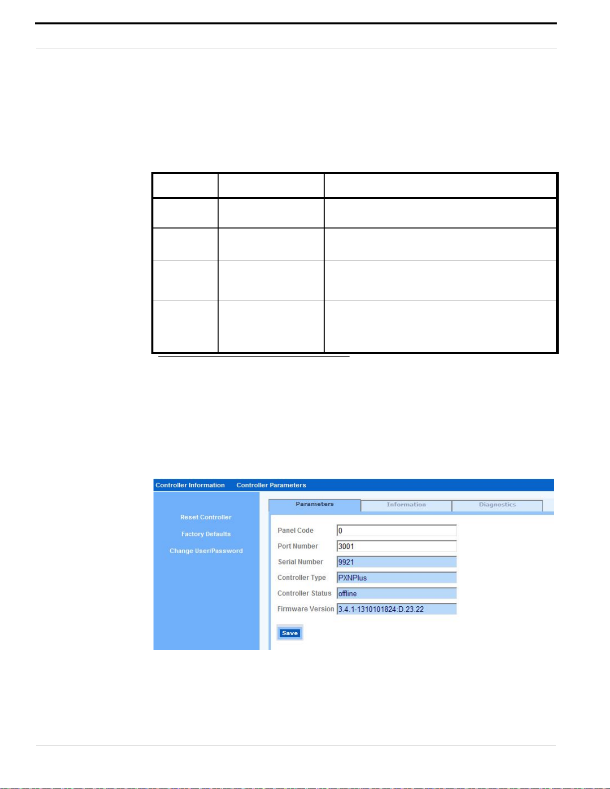
Controller Firmware Tools
• If you change any options on a form, you must click the Save button at the bottom of the form to
save your changes before switching to another form. This action saves your latest changes to a
temporary file.
• After completing all the forms, click Apply Changes and then click Restart Application for the
changes to take effect. Changes will be saved to the controller’s config file.
ICT Buttons and When to Use Them
Button Usage Result
Save After making changes
on any form
Reset
Controller
Factory
Defaults
Change
User/
Password
aa
a. If the default parameters are restored using the JP6 pin (refer to Pins and Jumpers on page 33), then all
parameters (including the IP of the controller) get modified.
After selecting Apply
a
Changes
To restore the
controller’s default
settings
To set the username
and/or password used
to log on to the ICT.
Saves the changes to the controller.
The operating system picks up the latest changes and
starts again.
The controller’s settings are restored to factory defaults.
The IP address settings of the controller are retained.
Changes the username and/or password for the ICT.
By default, these values are install, install.
For increased security, we recommend that you change
the default values.
Controller Information Menu > Parameters Form
Access the Controller Information menu and use the Parameters form to set the host Port Number.
Once the controller is configured, this form shows the controller’s serial number, the controller type,
the online/offline status, and the firmware build version.
Parameters Form
1. Click the Controller Information menu to open Parameters form.
2. Enter the host Port Number or accept the default port 3001.
3. Click Save.
4. If this completes your controller configuration, click Reset Controller.
84 M3000 Installation Guide
Page 85
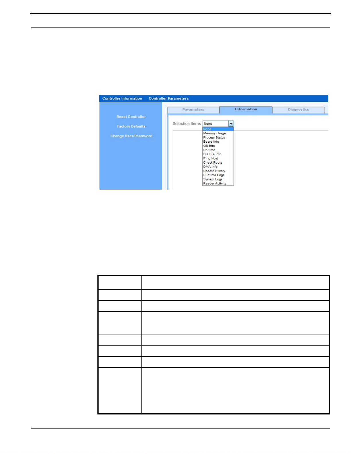
Integrated Configuration Tool (ICT)
Controller Information Menu > Information Form
Access the Controller Information menu and select the Information tab. The Information form
provides access to several status reports which are provided for checking and monitoring the
controller. These reports are used by technical support staff to troubleshoot controller issues.
Information Form > Selection Items
1. Click the Controller Information menu and then click the Information tab.
2. On the Information form, in the Select Items field, click the down arrow for a list of available
reports.
3. Select the desired report. Refer to table Controller Information Reports on page 85 for brief
descriptions of each report.
4. If technical assistance is needed, capture the report output by copying and pasting the output to a
text file (for example, using Notepad). Contact technical support on www.lenel.com.
Controller Information Reports
Report Description
Memory Usage Displays the amount of memory available, both used and free.
Process Status Lists which processes are running.
Board Info Displays hardware-related information, such as boot and board version, FPGA
version, SIMM type, available hardware devices, physical memory size
(SDRAM, BRAM, FLASH), and FLASH memory type.
OS Info Displays information related to the Linux operating system on the controller.
Up time Shows the time since the last reboot.
DB File Info Lists persistence-related database files.
Ping Host Pings the host from the controller (based on the current host IP or name).
• Example of a successful ping result:
2 packets transmitted, 2 packets received, 0% packet loss
• Example of a failed ping result:
2 packets transmitted, 0 packets received, 100% packet loss
M3000 Installation Guide 85
Page 86
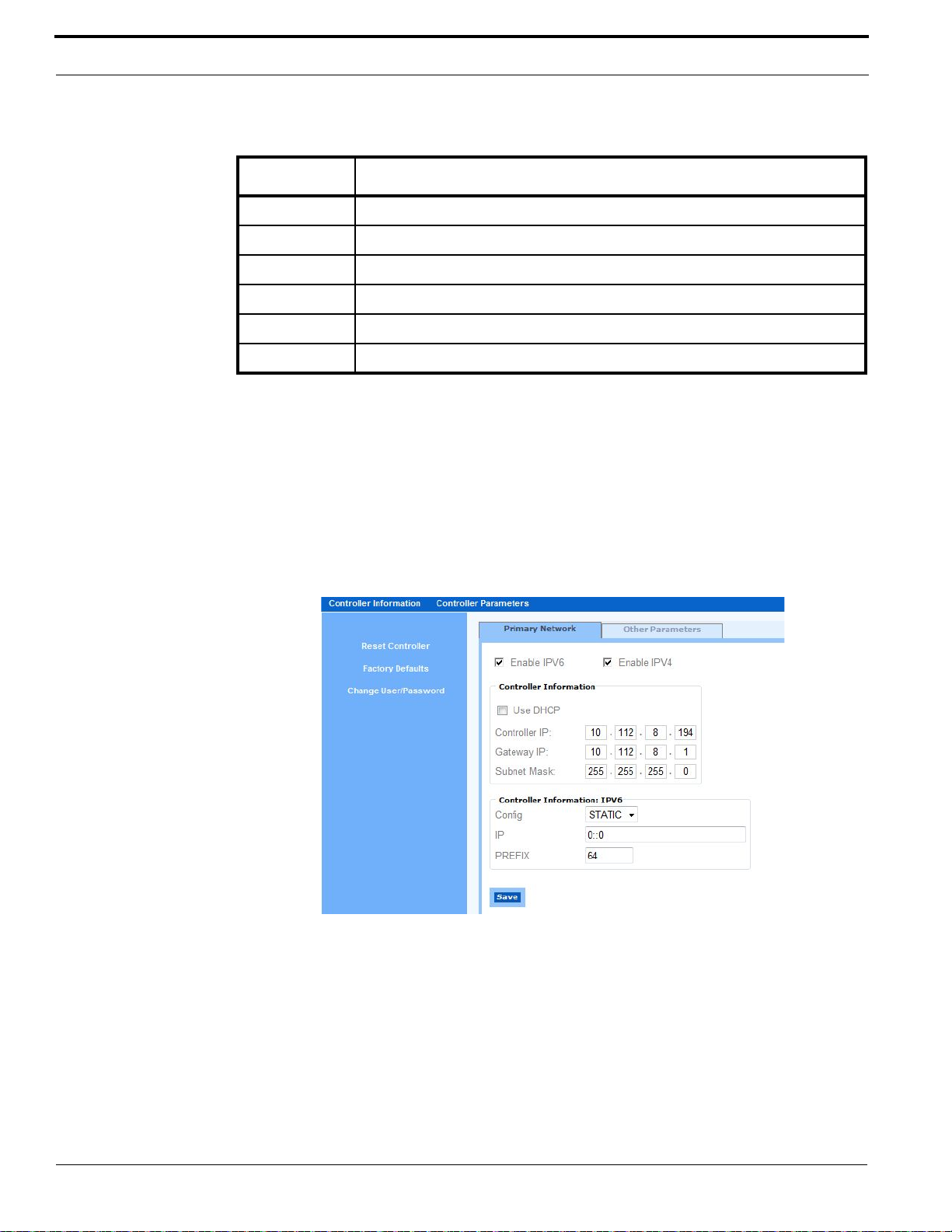
Controller Firmware Tools
Controller Information Reports (Continued)
Report Description
Check Route Checks route information from the controller.
DMA Info Shows the status of the DMA IO interface.
Update History Lists all updates to the firmware for the selected controller.
Runtime Logs Provides daily critical runtime information.
System Logs Provides daily critical system information.
Reader Activity Displays raw reader activity.
Controller Parameters Menu > Primary Network Form
Access the Controller Parameters menu and use the Primary Network form to configure the network
address settings for the controller. A static or dynamic IP address can be used for the controller.
Note: By default, the Enable IPV6 and Enable IPV4 check boxes are selected. At least one
of these check boxes must be selected. Deselecting Enable IPV4 hides the Controller
Information section. Deselecting Enable IPV6 hides the Controller Information:
IPV6 section.
Primary Network Form
IPV6 Configuration
1. Click the Controller Parameters menu and select the Primary Network form.
2. Make sure the Enable IPV6 check box is selected.
3. In the Controller Information: IPV6 section, select an option from the Config menu (STATIC,
AUTO, or DHCP).
• If STATIC is selected, enter the panel’s IP address in the IP field. Enter the prefix in the
PREFIX field (default is 64).
• If AUTO or DHCP is selected, no additional configuration is needed.
86 M3000 Installation Guide
Page 87
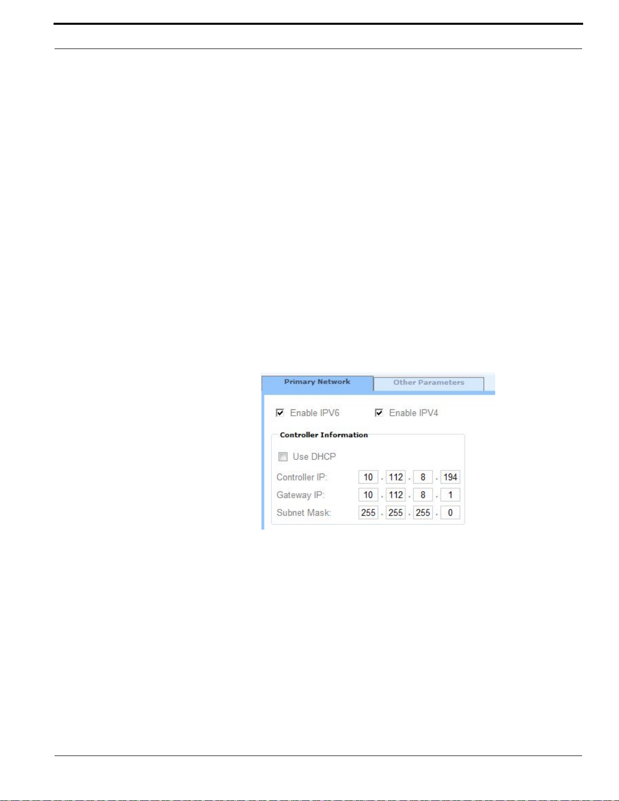
Integrated Configuration Tool (ICT)
4. Click Save.
5. If this completes your controller configuration, click Reset Controller.
IPV4 Configuration
1. Click the Controller Parameters menu and select the Primary Network form.
2. Make sure the Enable IPV4 check box is selected.
3. In the Controller Information section, set the controller IP addressing (Static) or dynamic
(DHCP). Refer to the appropriate section that follows.
Static:
1. Make sure the Use DHCP check box is not selected.
2. In the Controller IP field, enter the IP address of the controller given to you by your Network
Administrator.
3. You may accept the gateway IP generated based on the controller’s IP address or you may enter
the gateway IP address given to you by your Network Administrator in the Gateway IP field.
4. You may accept the subnet mask generated based on the controller’s IP address or you may enter
the subnet mask given to you by your Network Administrator in the Subnet Mask field.
5. Click Save.
6. If this completes your controller configuration, click Reset Controller.
Primary Network Form – Static IP Address
DHCP:
1. Select the Use DHCP check box.
2. Identify the controller by doing one of the following:
• Enter a name in the Controller Name field.
– or –
• Select the Use MAC address check box.
The MAC address for your controller board is displayed in the MAC address field.
Note: Give the MAC address to your Network Administrator so that it can be added to the
DNS database.
3. Click Save.
4. If this completes your controller configuration, click Reset Controller.
M3000 Installation Guide 87
Page 88
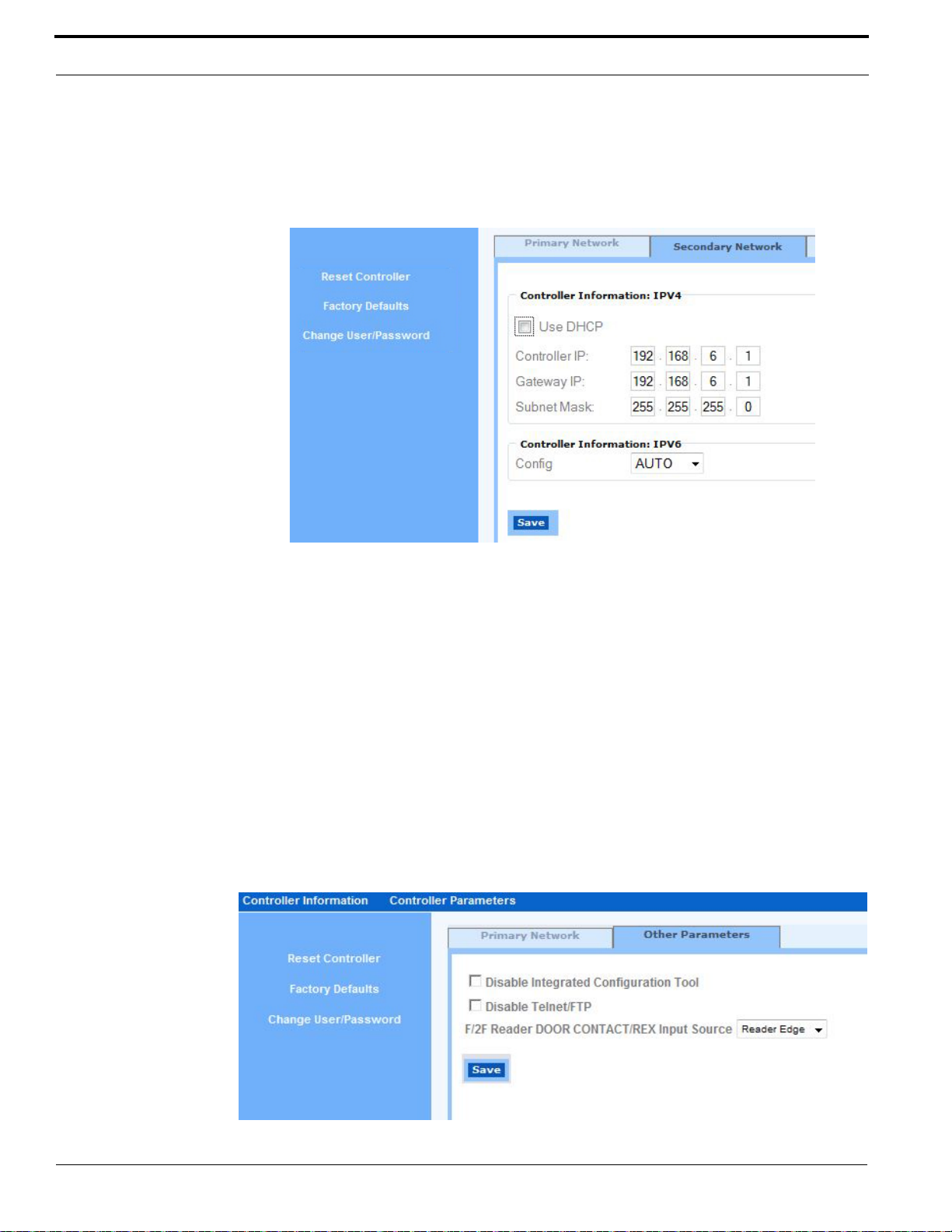
Controller Firmware Tools
Controller Parameters Menu > Secondary Network Form
If controller has a Dual Network Interface Card (NIC) installed, a Primary Network tab and a
Secondary Network tab are available from the Controller Parameters menu.
Secondary Network Form
To configure the Dual NIC:
1. Click the Controller Parameters menu and select the Primary Network form.
2. On the Primary Network form, select the Enable Secondary check box.
3. Click the Secondary Network tab.
4. In the Controller Information area of the Secondary Network form, set the static IP address or
select DHCP (refer to the instructions for the Controller Parameters Menu > Primary Network
Form on page 86.)
5. Click Save.
6. If this completes your controller configuration, click Reset Controller.
Controller Parameters Menu > Other Parameters Form
Access the Controller Parameters menu and use the Other Parameters form to enable/disable the ICT ,
enable/disable Telnet/FTP, and to select the door contact/request to exit (REX) input source options.
Other Parameters Form
88 M3000 Installation Guide
Page 89

Upgrading the Controller Firmware
• Disable Integrated Configuration Tool: Check this box to disable the ICT.
IMPORTANT: To ensure the security of the controller after configuration is complete, disable
the ICT. If the controller requires configuration updates after initial
configuration, re-enable the ICT. For more information, refer to Disable/
Enable the Integrated Configuration Tool (ICT) on page 89.
• Disable Telnet/FTP: Check this box to disable Telnet/FTP functions.
• F/2F Reader DOOR CONTACT/REX Input Source:
– Reader Edge: Door contact and REX are wired to reader, door junction box, or Wiegand
Interface Unit (WIU).
– Board Edge: Door contact and REX are terminated into inputs at the controller.
Disable/Enable the Integrated Configuration Tool (ICT)
Note: Disabling the ICT prevents access to the configuration parameters for the controller.
Disable the ICT only if necessary.
To disable the ICT:
1. Log into the ICT.
Refer to Connecting and Starting the Tool on page 83.
2. From the Controller Parameters menu, select Other Parameters.
3. Check the Disable Integrated Configuration Tool box and click OK.
4. To permanently disable the ICT, click Save.
The ICT web page closes and the ICT is permanently disabled.
To enable the ICT:
Note: The DS6 LED flashes once per second to indicate that the controller is in Normal
Operation Mode.
1. Short the JP4 jumper and wait while the DS6 LED completes the following sequence:
a. DS6 turns ON for approximately three (3) seconds.
b. DS6 turns OFF for one (1) second.
c. DS6 starts flashing once per second, indicating that the controller is in Normal Operation
Mode.
2. Remove the short from the JP4 jumper. The ICT is enabled.
Note: Shorting the JP4 jumper restores the controller’s default configuration. for more
information, refer to General Purpose Pins on page 33.
Upgrading the Controller Firmware
Note: Once the controller has the initial NGP-CASI firmware loaded (using ICT), you must
use Alarm Monitoring (not ICT) to upgrade to subsequent versions of the NGP-CASI
firmware.
M3000 Installation Guide 89
Page 90
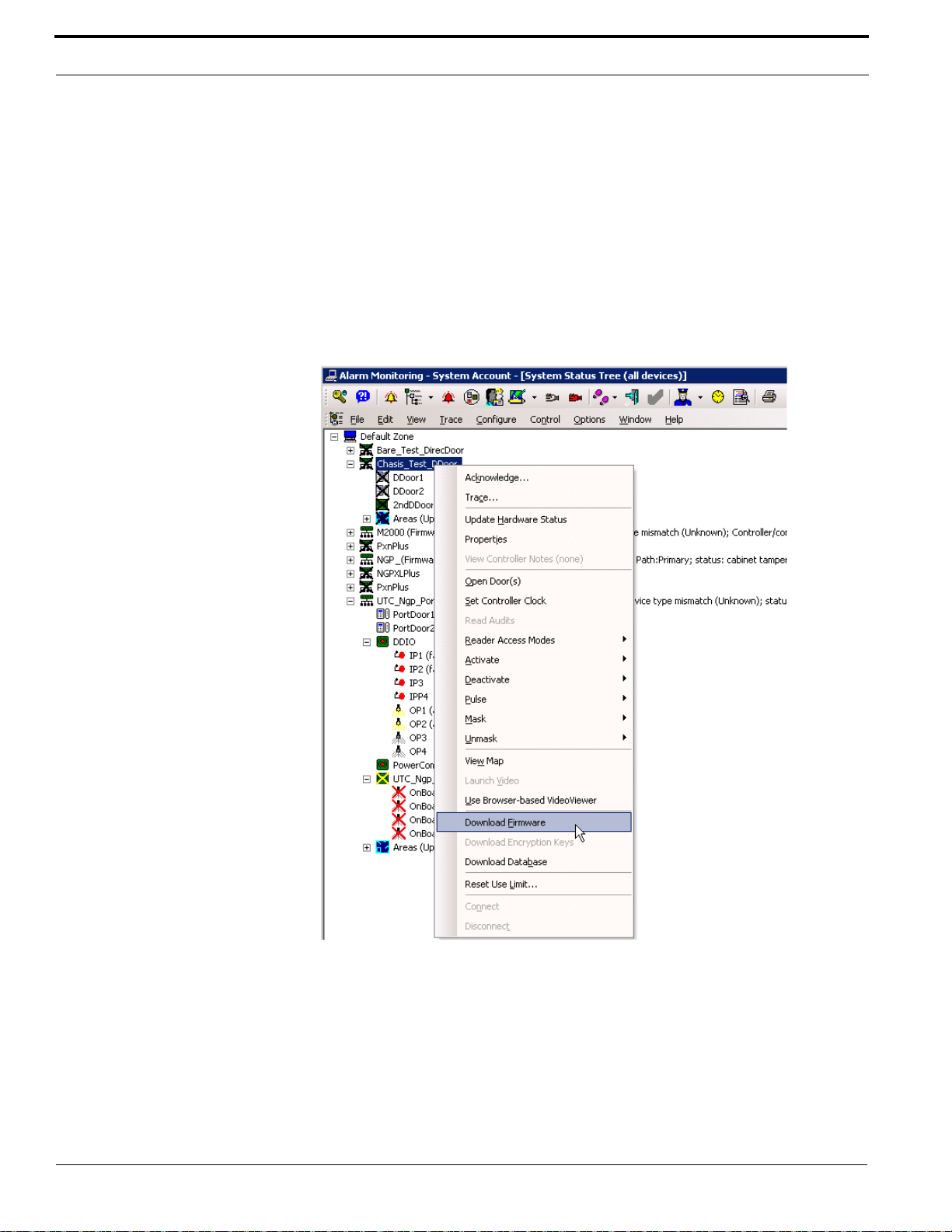
Controller Firmware Tools
• WARNING! • Do not reset or restart the controller in the middle of the flash process or the
controller will become nonfunctional.
1. Open the OnGuard Alarm Monitoring application and select the controller you are planning to
flash or upgrade in the main Alarm Monitoring window.
2. From the Control Menu > Current Device (the device name) submenu, select Download
Firmware.
– or –
Select View > System Status and then choose the desired view.
Right-click the controller in the hardware view and select Download Firmware.
Alarm Monitoring System Status Window
3. When the following message appears, click Yes to confirm the download
90 M3000 Installation Guide
Page 91
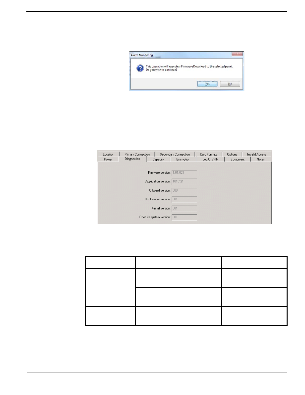
Upgrading the Controller Firmware
Firmware Download Confirmation
4. Wait for the firmware to download. After the download is completed, you should see a message
Firmware Download Completed in the Main Alarm Monitoring window.
5. Verify that the build version was updated in the Alarm Monitoring hardware view.
– or –
Check the controller’s firmware version in Diagnostics tab of the Access Panels folder in
System Administration application.
System Administration > Access Panels > Diagnostics
Configuration Checklist for the Integrated Configuration Tool
To complete controller configuration using the ICT, collect the following information:
Communication type Information needed Write your answer here
Use DHCP: NO Controller IP:
Gateway IP:
Subnet:
OnGuard Host IP:
Use DHCP: YES Controller Name or Controller MAC
Host Name:
M3000 Installation Guide 91
Page 92
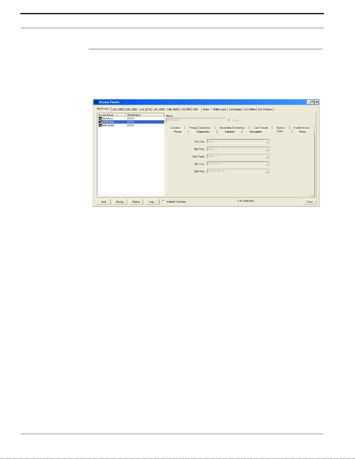
Controller Firmware Tools
Setting up the M3000 Controller in the Host Application
Set up this controller as you would any other NGP controller by using the NGP/CASI Form in the
Access Panels folder and selecting CASI M5/M3000 from the Model drop-down. Complete the
Options tab and the remaining tabs as applicable for your site.
Access Panels - NGP/CASI Form
For more information, refer to Access Panels Folder in the System Administration User Guide.
92 M3000 Installation Guide
Page 93

CHAPTER 9 Regulatory Information
CE (European) and FCC Compliance
As of January 1, 1996, all new European Union member installations must be CE compliant.
To make the M3000 installation CE and FCC compliant, the following conditions must be met:
• All cables connected to the M3000 must be shielded with shield terminated as shown in figure
T ypical Installation Using Shielded Cable/Drain Wire - Outside and Inside the Enclosure on page
94.
• The M3000 enclosure must be connected to the nearest earth ground. Refer to figure Earth
Ground Connection on page 95. Use #8-32 SEMS screw and #8 flat washer provided to secure
the ground lug.
• The Power/Communications board must be in the far right slot of the M3000 card cage and
grounded with a factory-installed braided wire as shown in figure Location and Grounding of the
Power/Communications and CPU Board on page 95.
• The CPU board must be in the second slot from the right of the M3000 card cage and grounded
with a factory-installed braided wire as shown in figure Location and Grounding of the Power/
Communications and CPU Board on page 95.
• Before connecting the network cable to connector J1, loop the cable through the Ferrite provided
and wrap cable around the Ferrite four times as shown in figure Installing Ferrite on page 96.
Note: Ferrite must be installed inside of the enclosure.
M3000 Installation Guide 93
Page 94
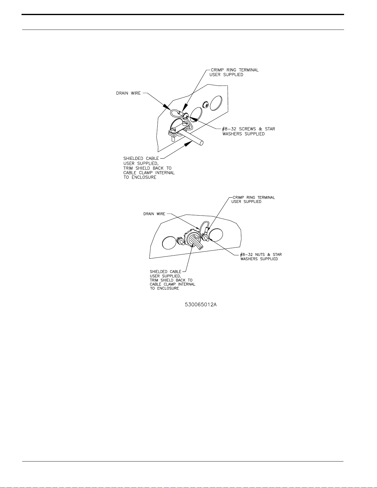
Regulatory Information
l
o
Typical Installation Using Shielded Cable/Drain Wire - Outside and Inside the Enclosure
Outside the enc
Inside the encl
94 M3000 Installation Guide
Page 95
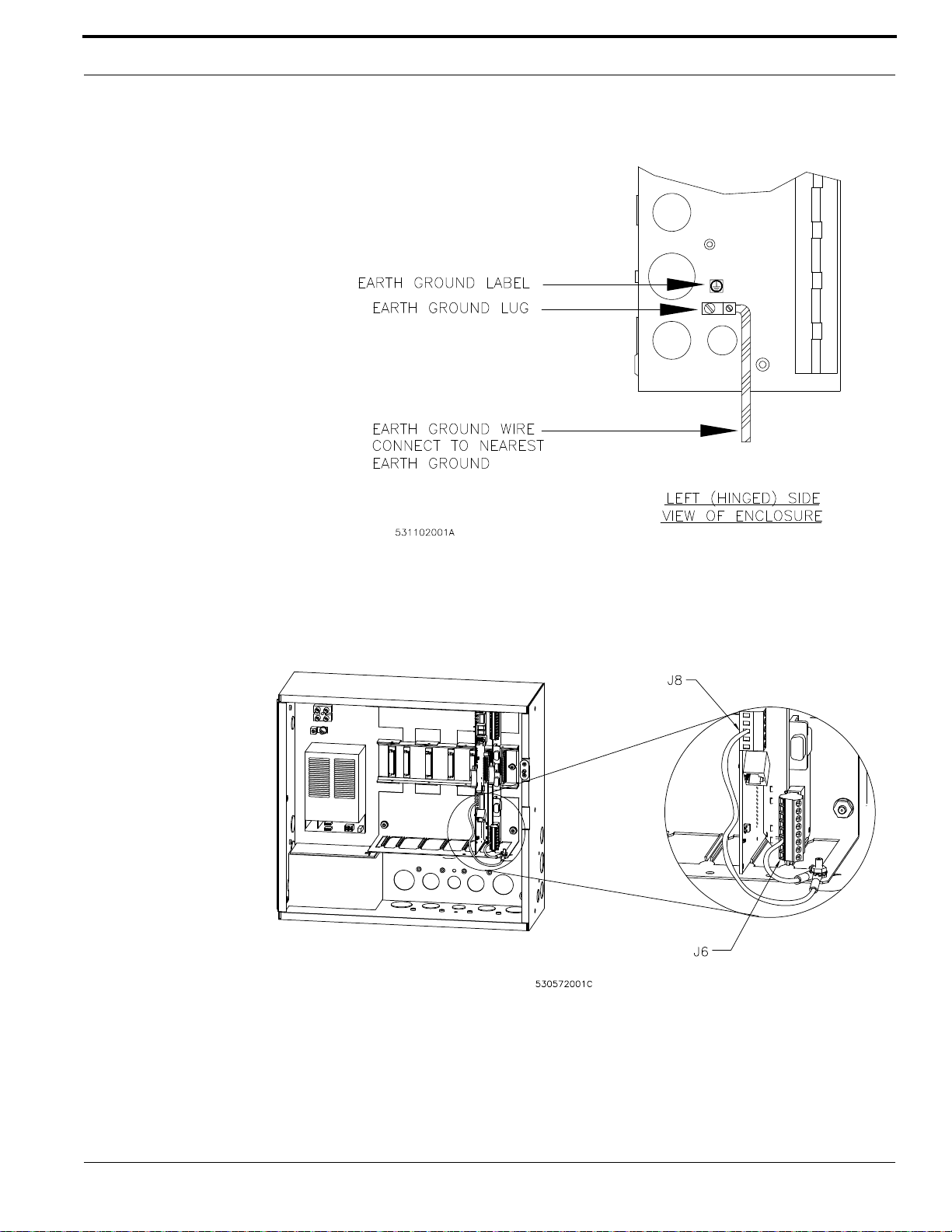
CE (European) and FCC Compliance
530572001C
J8
J6
Earth Ground Connection
Location and Grounding of the Power/Communications and CPU Board
M3000 Installation Guide 95
Page 96
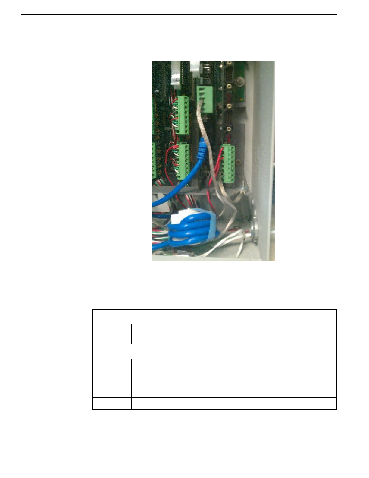
Regulatory Information
Installing Ferrite
UL Compliance
Ratings
Enclosure Specifications
Operating
environment
Boards and Devices
Reader
boards
16DO Output devices ratings: Digital outputs: 0.04 A @ 24 VDC
Failure to install and program the M3000 and OnGuard system in accordance with these instructions
voids the listing mark of Underwriters’ Laboratories, Inc.
96 M3000 Installation Guide
+32
°F to +120°F (+0°C to +49°C)
85% humidity
2RP Output devices ratings:
8RP Output devices ratings: Door DO (Reader LED) = 0.04 A @ 24 VDC
• Aux output (DO) relay = 2 A @ 30 VDC
• Alarm shunt relay = 2 A @ 30 VDC
Page 97
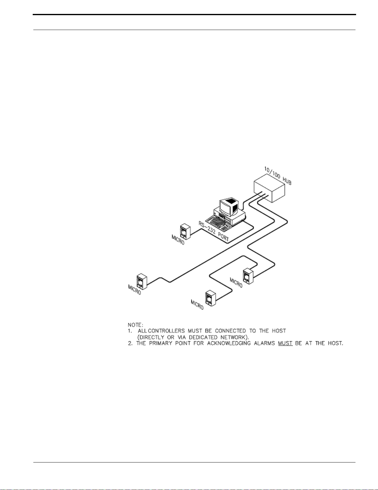
UL Compliance
A clearly marked redundant system with the same configuration as the primary machine must be
available as a backup.
The monitoring equipment must be protected by a Listed Transient Voltage Surge Suppressor with a
maximum rating of 330 V Listed under UL 1449. The communication circuit must be protected with
a Secondary Protector for Communication Circuits Listed under UL 497A.
The monitoring equipment must be installed in a temperature controlled environment with 24 hours
of standby power for the HVAC and computer system. In addition to the 24 hours of standby power, a
minimum of 15 minutes of standby power must be available to the computer system via a UPS
system. The UPS system must be Listed to UL 1778 or UL 1481 and must be provided with a
maintenance bypass switch.
An Altronix 3 A battery backup unit model AL400UL must be used.
UL-Approved System Configuration
The M3000 is UL Listed as an access control unit and a proprietary burglar alarm control unit (UL
1076 and UL 294). It should be used with the listed OnGuard system. The minimum configuration
consists of the M3000 with a 2RP or 8RP board and a 20DI board. The 20DI board must be used for
proprietary burglar alarm applications. The 2RP or 8RP board must be used for access control
applications.
• Operating environment: 32°F to 120°F (0°C to 49°C); Humidity: 85%
• Output Ratings: 2RP, 2SRP, 8RP reader boards - card reader outputs must be rated a minimum 11
to 12 VDC at 150 mA per output.
• Input Ratings: 120 VAC, 50/60 Hz, 0.9 A and 240 VAC, 50/60 Hz, 0.5 A
M3000 Installation Guide 97
Page 98

Regulatory Information
• M3000 must be used with the ESD model SPS-6.5 power supply or the Power One model
LWR1141-6EM3 power supply.
• The electrical rating of the battery is 12 VDC, 12 AH, sealed-lead acid battery.
• Grounding must be in accordance with Article 250 of the National Electrical Code.
• The M3000 controller must only be used with the following compatible card readers: Models
100, 940, 941, 970, 971, 972, 973, 820, 825, 840, 845, 430/435, 1000/1010, and 1100/1081.
• The exit request input circuit and initiating device must be contained within the secured area. The
exit device circuit must be connected to listed switches or exit devices.
• The M3000 must be mounted inside the secured area.
• The door strike power must be provided from a listed burglar alarm system power supply. If the
door strike circuit is arranged as fail secure (door remains locked upon loss of power), listed
emergency panic hardware must be provided to allow exit from the secured area. A fail-safe
configuration results in the door strike circuit unlocking in case of a power loss.
• The number of separate signals on a single channel shall be limited to 1000.
• Alarms on OnGuard should be set using the following priority list with 1 being the highest
priority and 7 being the lowest:
– Fire alarm and industrial supervision
– Hold-up or panic alarm
– Burglar alarm
– Watchman or guard tour
– Fire-alarm supervision
– Burglar-alarm supervision
– Industrial supervision
• A clearly marked redundant system with the same configuration as the primary machine should
be available as a backup.
• In order for this product to be UL-compliant, the firmware level must be R2.5 or later.
Notes: Removing all alarms from the Alarm Monitor should not be available to operators on
UL Listed systems.
Encryption is not investigated by UL.
WEEE
European Union directive:
The European directive “Waste Electrical and Electronic Equipment” (WEEE) aims to minimize the
impact of electrical and electronic equipment waste on the environment and human health. For proper
treatment, recovery and recycling, you can return the equipment marked with this symbol to your
local supplier upon the purchase of equivalent new equipment, or dispose of it in designated
collection points. Further information can be found on the following website: www.recyclethis.info
European representative for manufacture: UTC Fire & Security B.V., Kelvinstraat 7, 6003 DH Weert,
The Netherlands.
98 M3000 Installation Guide
Page 99
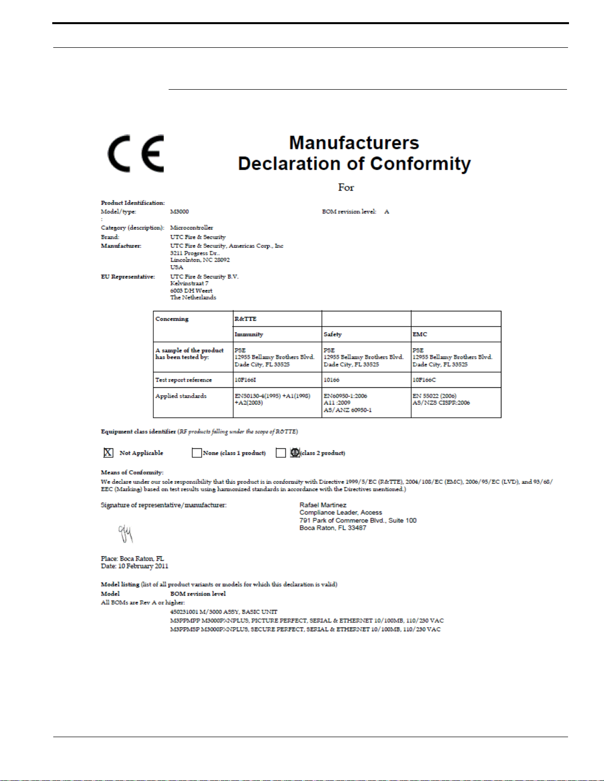
CE Regulatory Notice
CE Regulatory Notice
M3000 Installation Guide 99
Page 100

Regulatory Information
100 M3000 Installation Guide
 Loading...