

Page 1
OWNER’S MANUAL
Mobile Audio System
• PLL Synthesizer Stereo Radio
• RDS (Radio Data System) Operation
• Digital Compact Disc Player
• Automatic Memory Storing
• Full Detachable Panel
•Preset Equalization
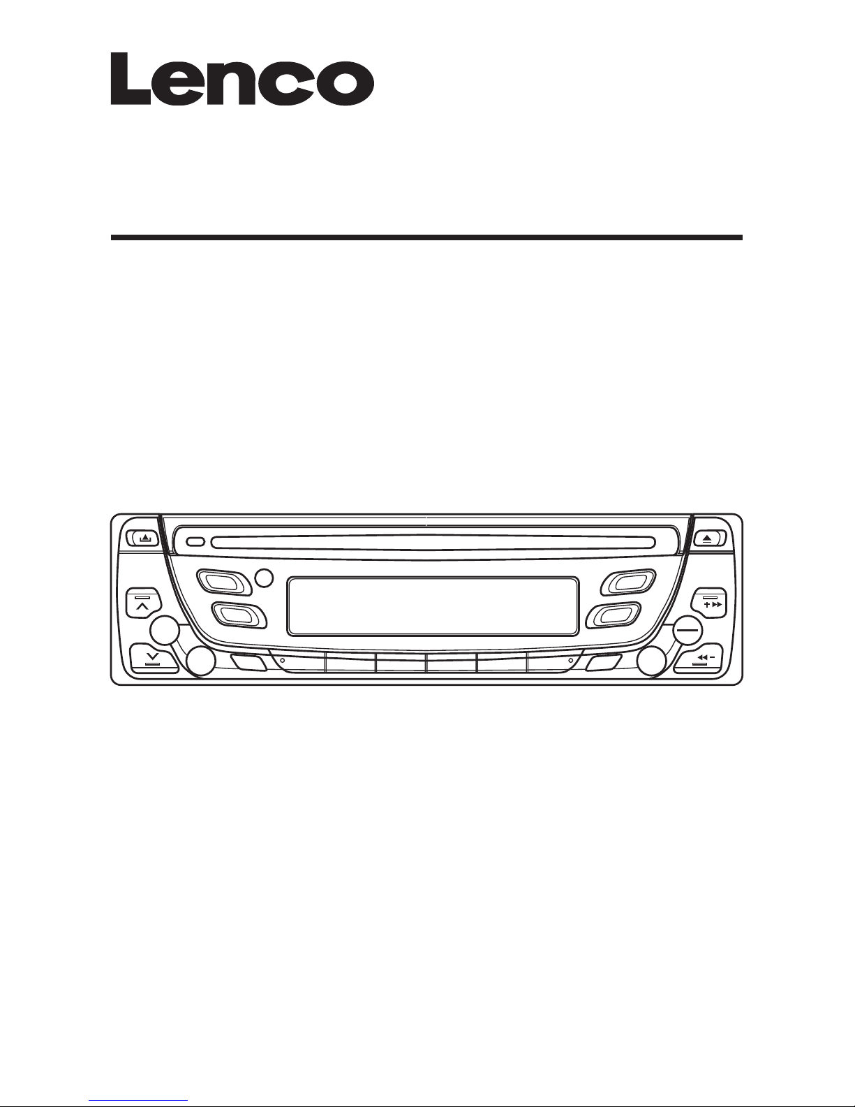
CS-1004 MP3
Page 2

CONTENTS
Installation ...........................................3
Take out screw before installation.........3
DIN Front-Mount (Method A) ................3
Installing the unit.................................3
Removing the unit...............................4
DIN Rear-Mount (Method B) .................5
Using the detachable front panel ......6
Wiring Connection ..............................7
Operation .............................................8
Location of keys....................................8
Switching on/off the unit.......................9
Faceplate release..................................9
Sound adjustment.................................9
Loudness ............................................10
Display ................................................10
Equalization.........................................11
Liquid crystal display ..........................11
Reset function.....................................11
Radio operation ..................................11
Switching to radio mode ................11
Selecting the frequency band ........11
Selecting station.............................11
Automatic memory storing &
program scanning ..........................11
Station storing ................................11
R.D.S.
(radio data system) operaation..........11
CD operation.......................................13
Switching to CD mode ...................13
Selecting tracks..............................13
Pausing playing ..............................13
Previewing all tracks.......................13
Repeating the same track ..............13
Playing all tracks in random ...........14
Ejecting a disc ................................14
MP3 operation ....................................14
Disc notes ...........................................17
Specification......................................18
Trouble shooting ...............................19
GB-2
Page 3
INSTALLATION
Notes:
• Choose the mounting location where
the unit will not interfere with the
normal driving function of the driver.
• Before finally installing the unit,
connect the wiring temporarily and
make sure it is all connected up
properly and the unit and the system
work properly.
• Use only the parts included with the
unit to ensure proper installation.
The use of unauthorized parts can
cause malfunctions.
• Consult with your nearest dealer if
installation requires the drilling of holes
or other modifications of the vehicle.
• Install the unit where it does not get in
the driver’s way and cannot injure the
passenger if there is a sudden stop,
like an emergency stop.
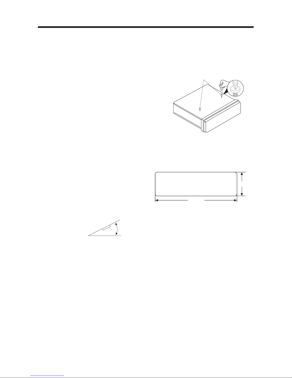
• If installation angle exceeds 30˚ from
horizontal, the unit might not give its
optimum performance.
•Avoid installing the unit where it would
be subject to high temperature, such
as from direct sunlight, or from hot air,
from the heater, or where it would be
subject to dust, dirt or excessive
vibration.
DIN FRONT/REAR-MOUNT
This unit can be properly installed either
from “Front” (conventional DIN Frontmount) or “Rear” (DIN Rear-mount
installation, utilizing threaded screw holes
at the sides of the unit chassis).
For details, refer to the following
illustrated installation methods.
TAKE OUT SCREW BEFORE
INSTALLATION
Before install the unit, please remove the
two screws.
DIN FRONT-MOUNT (Method A)
Installation Opening
This unit can be installed in any dashboard
having an opening as show below:
Installing the unit
Be sure you test all connections first, and
then follow these steps to install the unit.
1. Make sure the ignition is turned off,
and then disconnect the cable from
the vehicle battery's negative (-)
terminal.
2. Disconnect the wire harness and the
antenna.
3. Press the release button on the front
panel and remove the control panel
(see the steps of “using the detachable
front panel”).
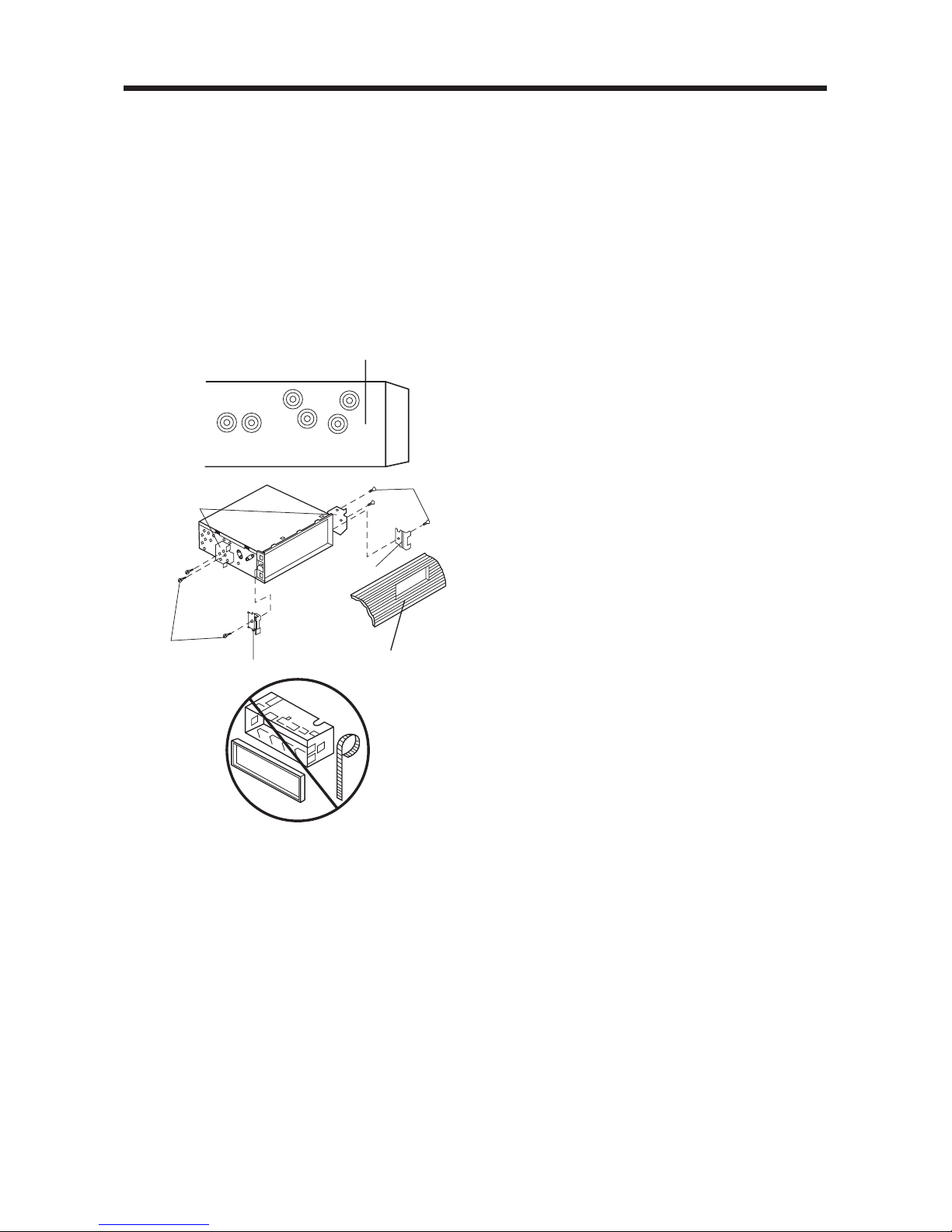
4. Lift the top of the outer trim ring then
pull it out to remove it.
5. The two supplied keys release tabs
inside the unit's sleeve so you can
remove it. Insert the keys as far as they
will go (will the notches facing up) into
the appropriate slots at the middle left
and right sides of the unit. Then slide
the sleeve off the back of the unit.
30˚
182 mm
53 mm
Take out screw before installation
GB-3
Page 4

INSTALLATION
6. Mount the sleeve by inserting the sleeve
into the opening of the dashboard and
bend open the tabs located around the
sleeve with a screwdriver. Not all tabs
will be able to make contact, so
examine which ones will be most
effective. Bending open the appropriate
tabs behind the dashboard to secure
the sleeve in place.
7. Reconnect the wire harness and the
antenna and be careful not to pinch
any wires or cables.
8. Slide the unit into the sleeve until it
locks into place.
9. To further secure the unit, use the
supplied metal strap to secure the back
of the unit in place. Use the supplied
hardware (Hex Nut (M5mm) and Spring
Washer) to attach one end of the strap
to the mounting bolt on the back of
the unit. If necessary, bend the metal
strap to fit your vehicle's mounting
area. Then use the supplied hardware
(Tapping Screw (5x25mm) and Plain
Washer) to attach the other end of
metal strap to a solid metal part of the
vehicle under the dashboard. This strap
also helps ensure proper electrical
grounding of the unit.
Front Panel
Outer Trim Ring
L Key
Sleeve
R Key
Sleeve
Dashboard
Screwdriver
Tabs
Spring Washer
Tapping Screw
Plain Washer
Hex Nut
Metal Strap
Mounting Bolt
10. Reconnect the cable to the vehicle
battery's negative (-) terminal. Then
replace the outer trim ring and install
the unit's front panel. (see the steps
of “using the detachable front panel”).
Removing the unit
1. Make sure the ignition is turned off,
and then disconnect the cable from
the vehicle battery's negative (-)
terminal.
2. Remove the metal strap attached the
back of the unit (if attached).
3. Press the REL button to remove the
front panel.
4. Lift the top of the outer trim ring then
pull it out to remove it.
5. Insert both of the supplied keys into
the slots at the middle left and right
sides of the unit, then pull the unit out
of the dashboard.
GB-4
Page 5
DIN REAR-MOUNT (Method B)
If your vehicle is a Nissan, Toyota, follow
these mounting instructions. Use the
screw holes marked T (Toyota), N (Nissan)
located on both sides of the unit to fasten
the unit to the factory radio mounting
brackets supplied with your vehicle.
To fasten the unit to the factory radio
mounting brackets.
1. Use a screwdriver to loose the hook's
screws on the front left and right sides
of the unit and remove the hooks.
2. Align the screw holes on the bracket
with the screw holes on the unit, and
then tighten the screws (5x5mm) on
each side.
Note: the outer trim ring, sleeve and the
metal strap are not used for method B
installation.
INSTALLATION
Dashboard or
Console
Side view showing
Screw Holes marked
T, N
Factory Radio
Mounting
Bracket
Hook
Screw
Screw
Hook
GB-5
Page 6
USING THE DETACHABLE FRONT PANEL
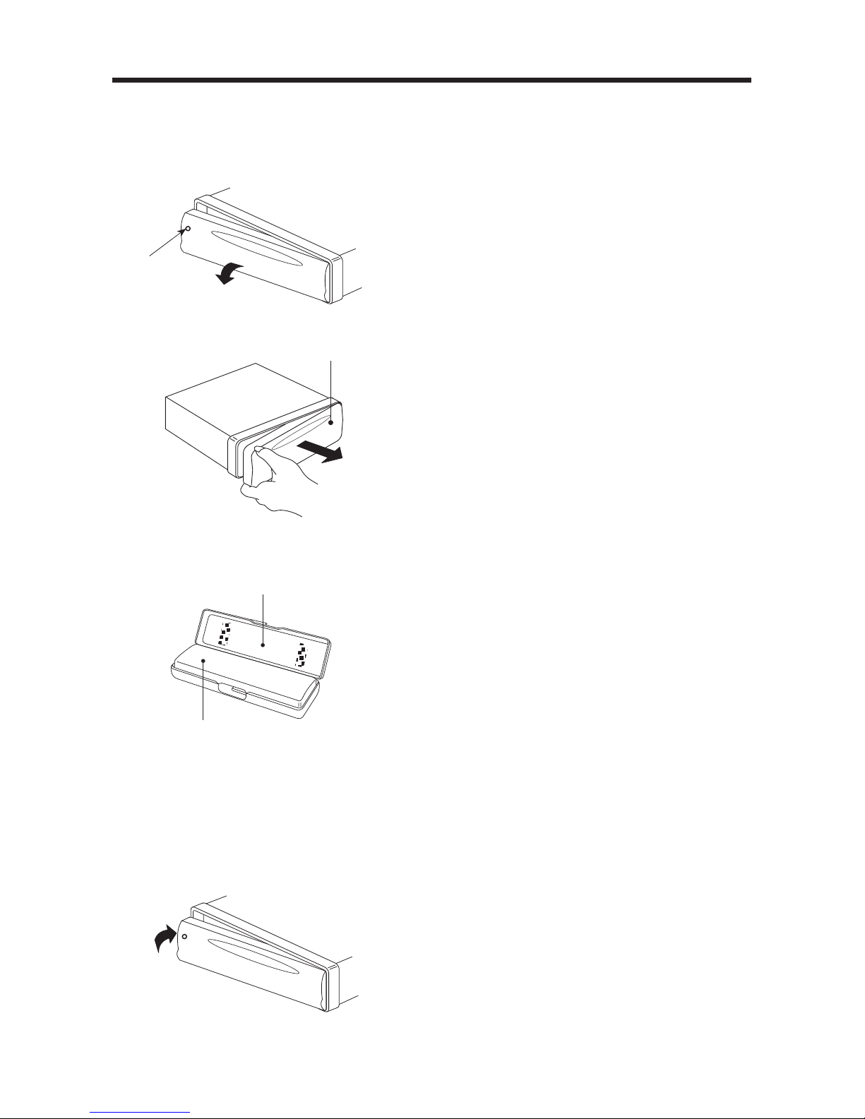
REMOVING THE FRONT PANEL
1. Press the release button (REL) on the
front panel and pull off the front panel.
2. Keep front panel into the case.
INSTALLING THE FRONT PANEL
To install the front panel, insert the panel
into the housing and make sure the panel
is properly installed. Otherwise,
abnormality occurs on the display or some
keys will not function properly.
Release Button
Front Panel
Protective Case
Front Panel
Precautions when handing
1. Do not drop the front panel.
2. Do not put pressure on the display or
control buttons when removing or
installing the front panel.
3. Do not touch the contacts on the front
panel or on the main unit body. It may
result in poor electrical contact.
4. If any dirt or foreign substances
adhered on the contacts, they can be
removed with a clean and dry cloth.
5. Do not expose the front panel to high
temperatures or direct sunlight in
anywhere.
6. Keep away any volatile agents (e.g.
benzene, thinner, or insecticides) from
touching the surface of the front panel.
7. Do not attempt to disassemble the
front panel.
GB-6
Page 7

WIRING CONNECTION
ISO Connection
ISO SOCKET PIN OUT
Part A Power Connection Part B Speaker Connection
1. Free 1 +
2. Free 2 –
3. Free 3 +
4. Memory (+B permanent) 4 –
5. Trip line for fully automatic antenna 5 +
6. Free 6 –
7. Main power supply (+B ignition) 7 +
8. Ground 8 –
Part C
1. Audio frequency out, rear left
2. Audio frequency out, rear right
3. Audio frequency out, ground
4. Battery plus, switched by radio
RR = Rear right
RF = Front right
LF = Front left
LR = Rear left
BLUE
14710131619
369121518
25811141720
13 5 7
24 6 8
13 5 7
24 6 8
Part C
Part B
Part A
AUTO ANTENNA
Rch RED
Lch WHITE
BROWN
GB-7
Page 8

OPERATION
LOCATION OF KEYS
14
4
2 16
17
138
910
711 1
12 3 20 21 6
22
23 19
18 15
5
24
GB-8
Page 9

OPERATION
SWITCHING ON/OFF THE UNIT
Switch on the unit by pressing any button
(except REL button (7) and EJECT
button (4)). When system is on, press
PWR button (9) to turn off the unit.
FACEPLATE RELEASE
Press REL button (7) to detach the
removable faceplate.
SOUND ADJUSTMENT
Press SEL button (10) shortly to select
the desired adjustment mode.
The adjustment mode will change in the
following order:
By pressing the AUDIO SELECT
button (11) or AUDIO SELECT
button (12), it is possible to adjust the
desired sound quality.
Press SEL Button (10) for several
seconds, it is activated as cyclical
mode of following functions for user’s
selection.
a) TA SEEK or TA ALARM
- TA SEEK mode:
When newly tuned station does not
receive TP information for several
seconds, the radio retunes to next
station which has not the same
station (PI) as the last station, but
has the TP information.
When TP information gets lost at
the current station for retune time
which is set by RETUNE SHORT
(30 sec.) or RETUNE LONG (90
sec.), the radio start to retune to
next same PI station.
When same PI station does not
catch in 1 cyclic search, the radio
retunes to next station with TP
information.
-TA ALARM mode:
When this mode is selected, any
automatic retune mode is not
activated. Only double beep sound
(ALARM) is output.
When newly tuned station does not
have TP information for several
seconds, beeps come out.
When TP information gets lost at
the current station for retune time,
the beep sound is out-putted.
When newly tuned station has not
RDS signal, “PI SEEK” is
suppressed somewhat.
b) PI SOUND or PI MUTE
While AF switching is implemented
in C201 station, AF can switch to
100 MHz, which is non genuine AF
(where, different PI with same AF) in
short “DIP”.
If a car cruises that critical area back
and forth, an oscillation
phenomenon can be occurred,
because the different PI code can
be received from 100 MHz with
“XXX” PI.
The car radio has special procedure
to reduce even this kind of
unavoidable situation however there
is a limit to be escaped from this
serious case perfectly.
In that serious case, 2 mode is
selectable as follows:
- PI SOUND mode:
When above different PI sound
(DIP) is heard once in a while, the
DIP’s sound will be heard for a
short time.
- PI MUTE mode:
Under above same situation, a
mute sound will be heard for a
short time.
VOL BAS TRE BAL FAD
(Volume) (Bass) (Treble) (Balance) (Fader)
TA SEEK or ALARM PI SOUND or MUTE
MASK DPI or ALL RETUNE L or S
BEEP 2’nd, ALL or OFF
100
90
98
100
PI : C201 PI : XXX
GB-9
Page 10

OPERATION
c) RETUNE L, RETUNE S mode
The initial time of automatic TA
search or PI search mode is selected.
When PI information is not caught for
retune time, the radio start to retune
to next same PI station. When same
PI station does not catch 1 cyclic
search, the radio goes to last station
and waits for several minutes until PI
code is received.
- RETUNE L mode:
Selected as 90 seconds.
- RETUNE S mode:
Selected as 30 seconds.
d) MASK DPI or MASK ALL mode
The AF frequency (which has
different PI or NO R.D.S. signal with
high field strength) is masked during
checking PI when the unit searches
AF. The unit doesn’t search this AF
(DIP) for few minutes. In the case
of the AF of NO R.D.S. signal with
high field strength, if the real AF is
wrongly masked as DIP by some
interference, the unit hesitates to
search real Afs. For this reason, the
unit has the user option (MASK DPI)
which doesn’t mask the AF of NO
R.D.S. signal with high field strength.
In MASK DPI mode, the wrong
sound or long mute (according to PI
SOUND or PI MUTE) can be heard
from the AF station which has NO
R.D.S. signal and of which the field
strength is higher than that of the
currently tuning AF (station).
But, these phenomenon are rare
and the user will hardly hear the
wrong sound in whole Europe.
- MASK DPI mode:
Masked only the AF which has
different PI.
- MASK ALL mode:
Masked the AF which has
different PI and NO R.D.S. signal
with high field strength.
e) BEEP 2’ND, BEEP ALL, BEEP OFF
mode
The situation of beep sound is
selected. The 3 mode is selected as
also pressng AUDIO SELECT
button (11) or AUDIO SELECT
button (12).
- BEEP 2’nd mode:
The beep is only generated when
all allowed double key is pressed
long (1 sec).
e.g.
When preset button (14) is
pressed.
When BND/LOU button (13) is
pressed.
When AMS button (18) is pressed.
- BEEP ALL mode:
The beep is generated when
every key is pressed.
- BEEP OFF mode:
The beep is disabled.
LOUDNESS
Press BND/LOU button (13) for several
seconds to reinforce the bass output.
Press it for several seconds again to
release this function.
DISPLAY
Press DSP button (15) to operate as
the conversion of each display mode
as follows:
- In case of receiving a RDS station
In radio mode:
-> PS -> CT -> FREQ. -> PTY ->
In CD mode:
-> CD -> CT -> PS -> FREQ. ->
PTY ->
- In case of no receiving CT or PTY
information, the display shows as
“NO CLOCK” or “NO PTY”.
-
In case of receiving a non RDS station
In radio mode:
-> “NO CLOCK” -> FREQ. ->
“NO PTY” ->
In CD (MP3) mode:
-> CD (MP3) -> CT -> FREQ. ->
GB-10
Page 11

OPERATION
“NO PTY” ->
Each displaying time is several
seconds, and come back to 1’st
position after several seconds.
Notes:
- CT = clock time
- FREQ. = frequency
EQUALIZATION
Press PEQ button (19) to turn on
equalization function and to select
desired audio mode. There are five kinds
of mode as below:
LIQUID CRYSTAL DISPLAY
Exhibit current frequency and activated
functions on the display (8).
RESET FUNCTION
RESET
button (24) must be activated
with either a ballpoint pen or thin metal
object.
The RESET button is to be activated for
the following reasons:
- Initial installation of the unit when all
wiring is completed.
- All the function buttons do not operate.
- Error symbol on the display.
Note: If press RESET button (24), the
unit can’t work yet, please use a cotton
swab soaked in isopropyl alcohol to
clean the socket on the back of the front
panel.
RADIO OPERATION
• SWITCHING TO RADIO MODE
Press MOD button (6) shortly to
select radio mode, the radio mode
appears in the display together with
the memory band and frequency.
• SELECTING THE FREQUENCY
BAND
At radio mode, press BND/LOU
button
(13) shortly to select the desired
band.
FLAT CLASSICS POP M ROCK M DSP OFF
The reception band will change in the
following order:
• SELECTING STATION
Press TUNE/SEEK/TRACK
button (17) or TUNE/SEEK/TRACK
button (16) shortly to activate
automatic seek function. Press for
several seconds until “MANUAL”
appeared on the display, the manual
tuning mode is selected. If both
buttons have not pressed for several
seconds, they will return to seek tuning
mode and “AUTO” appeared on the
display.
• AUTOMATIC MEMORY
STORING & PROGRAM SCANNING
- Automatic memory storing
Press AMS button (18) for several
seconds, the radio searches from
the current frequency and checks
the signal strength until one cycle
search is finished. And then 6
strongest stations are stored into the
corresponding preset number
button.
- Program scanning
Press AMS shortly to scan preset
station. When the field strength level
is more than the threshold level of
stop level, the radio is holding at that
preset number for several seconds
with release mute, then searches
again.
• STATION STORING
Press any one of the preset buttons
(14) (1 to 6) to select a station, which
had been stored in the memory. Press
this button for several seconds, (Until
2’nd beeps come out), current station
is stored into the number button.
• R.D.S. (RADIO DATA SYSTEM)
OPERATION
- Setting R.D.S. Mode
Press AF/REG button (3) and release
FM1 FM2 FM3
GB-11
Page 12

OPERATION
immediately to switch on or off R.D.S.
mode.
Whenever R.D.S. is switched on,
symbol “AF” appears on the display.
Program name is displayed on
receiving a R.D.S. station.
“AF” starts blinking if the
broadcasting signal getting worse.
“ALARM” will be displayed when an
emergency broadcasting is received;
meanwhile sound output level will be
adjusted to the preset output level
automatically when the volume
control is set at minimum.
- Regional Program Operation
Press AF/REG button (3) for several
seconds to switch on or off region
mode.
Some broadcasting stations change
their program from normal
broadcasting to regional
broadcasting for a certain time
period. When region is on, the
current listening program remains
unchanged. When region is off, it
allows the reception moves to the
regional station.
- Using PTY to Select Program
PTY button (1) is operated as follows:
While selecting PTY engagement, its
selection is implemented by preset
buttons as described in notes.
When PTY is selected, the radio
starts to search corresponding PTY
information, and stops if the
corresponding PTY information is
detected.
If corresponding PTY information is
not existed any more, PTY engaging
is automatically exit to normal mode.
Notes:
When PTY mode is engaged, the
PTY switch is shared as follows:
According to above 2 allotted group,
the preset number is used for PTY
selection as follows:
MUSIC group
- POP M, ROCK M
- EASY M, LIGHT M
- CLASSICS, OTHER M
- JAZZ, COUNTRY
-NATION M, OLDIES
- FOLK M.
SPEECH group
- NEWS, AFFAIRS, INFO
- SPORT, EDUCATE, DRAMA
- CULTURE, SCIENCE, VARIED
- WEATHER, FINANCE,
CHILDREN
- SOCIAL, RELIGION, PHONE IN
- TRAVEL, LEISURE,
DOCUMENT
- Listening to Traffic Announcement
TA button (2) is operated as follows:
When pressed short, it is engaging
whether TA mode on or off.
When TA mode, is on and a traffic
announcement is transmitted:
When the unit was in CD (MP3)
mode, it will switch temporarily to
radio mode.
Temporary switch over to an R.D.S.
linked station when R.D.S. detects a
traffic announcement on that other
program. If the volume level was
under the threshold point it will be
raised to the threshold point.
But the user changed the volume
level which was more than the
threshold point (min. TA volume
level), it will be set to the last level.
When TA mode is on, TA of individual
segment is turned on.
When a TP station is received, TP of
individual segment is turned on.
TA interruption function
The current traffic announcement is
cancelled by pressing this key.
But the TA mode will not be off.
When pressed long, it is selected
R.D.S. TA LOCAL/R.D.S. TA
DISTANCE mode.
The purpose of this key is to reduce
wanted R.D.S. TA switching, which
PTY MUSIC group PTY SPEECH group PTY off
PTY MUSIC group PTY SPEECH group PTY off
GB-12
Page 13

OPERATION
R.D.S. TA information was received
from current station and the radio
switched to that R.D.S. linked station,
but no information could not be
received because the R.D.S. linked
station is located too far from that
area. So the radio is switched back
to current station again.
In above operation, a customer listen
to a wrong program or mute sound
for a while.
R.D.S. TA LOCAL mode
When the filed strength level of R.D.S.
linked is less than threshold level,
the radio does not switch that station,
and a customer can hardly listen to
any disturbances.
When R.D.S. TA LOCAL mode is
selected, “R.D.S. TA LO” on numeric
display is indicated for a few
seconds.
R.D.S. TA DISTANCE mode
R.D.S. TA switching is try to
implemented by the information of
current station.
When R.D.S. TA DISTANCE mode is
selected, “R.D.S. TA DX” on numeric
display is indicated for a few
seconds.
The RDS data used are the PI, PS,
AF, TP, TA, R.D.S. and PTY data.
PI: Program Identification Code
Code for identifying programs
PS: Program Service Name
Broadcast station name data
expressed in
alphanumerically characters
AF: Alternative Frequencies
Frequency list of
broadcasting stations
transmitting the same
program
TP: Traffic Program Identification
Identification data for traffic
information broadcasting
station
TA:Traffic Announcement
Identification Identification
data showing traffic
information is being
transmitted or not
R.D.S.: Enhanced Other Networks
Information Broadcasting
information on PI, AF, TP, TA,
etc. relating to networks other
than the network used for
current reception
PTY:Program Type Code Contents
of programs such as news,
light music, sports etc.
CD OPERATION
• SWITCHING TO CD MODE
If there is no CD inserted in the driver:
Gently insert the CD with the printed
side uppermost into the CD
compartment until you feel some
resistance. The CD is drawn into the
drive automatically. CD playback
begins.
If a CD is already inserted in the driver:
Keep pressing MOD button (6)
shortly until the CD mode display
appears.
• SELECTING TRACKS
Press TUNE/SEEK/TRACK
button (16) or TUNE/SEEK/TRACK
button (17) to move the previous
track or the following track. Track
number shows on display.
Hold TUNE/SEEK/TRACK
button (16) or TUNE/SEEK/TRACK
button (17) to fast reverse or fast
forward. CD play starts from when you
release the button.
• PAUSING PLAYING
Press PAU button (20) to pause CD
player. Press it again to resume play.
• PREVIEWING ALL TRACKS
Press SCN button (21) to play first
several seconds of each track on the
current disc. Press it again to stop
intro and listen to track.
• REPEATING THE SAME TRACK
Press RPT button (22) to continuously
repeat the same track. Press it again
to stop repeat.
GB-13
Page 14

OPERATION
• PLAYING ALL TRACKS IN RANDOM
Press SHF button (23) to play all
tracks on CD in random order. Press
again to cancel the function.
• EJECTING A DISC
Press EJECT button (4) to stop CD
playing and eject the disc from the
disc slot (5).
Note: When you first play a CD and
when whichever track is playing, press
M5 button (24) or M6 (25), the unit will
search the disc again and start to play
the first track. Later, there is no
function of pressing M5 button (24) or
M6 button (25).
MP3 OPERATION
• SWITCHING TO CD (MP3) MODE
If there is no MP3 disc inserted in the
driver:
Gently insert the MP3 disc with the
printed side uppermost into the disc
slot (5) until you feel some resistance.
The MP3 disc is drawn into the driver
automatically. The MP3 playback
begins.
If a MP3 disc is already inserted in the
driver:
Keep pressing MOD button (6) shortly
until the CD (MP3) mode display
appears.
• EJECTING A DISC
Press EJECT button (4) to stop MP3
playing and eject the disc from the disc
slot (5).
• SELECTING TRACKS IN SINGLE
STEP
Press TUNE/SEEK/TRACK
button (16) or TUNE/SEEK/TRACK
button (17 to move to the
previous track or the following track.
Track number shows on display.
• SELECTING DIRECTORY UP/ DOWN
Press M5 button or M6 button to
select directory downward or upward.
If the MP3 disc does contain any
directory, there is no function of
pressing M5 button or M6 button.
•PAUSING PLAYING
Press PAU button (20) to pause MP3
player. Press it again to resume play.
• PREVIEWING ALL TRACKS
Press SCN button (21) to play first
several seconds of each track on the
current disc. Press again to stop intro
and listen to track.
• REPEATING THE SAME TRACK
Press RPT button (22) to continuously
repeat the same track. Press it again
to stop repeat.
• PLAYING ALL TRACKS IN RANDOM
Press SHF button (23) to play all tracks
on MP3 disc in random order. Press
again to cancel the function.
• SELECTING TRACKS BY AMS/MPS
(MP3) BUTTON
AMS button is assigned as Digital
Audio Mode selection button in MP3
operation.
When pressed, it is activated as
selecting each mode of Digital Audio.
“Searching track directly” =>
“Searching Directory or File Name”=>
“Navigation” from root by
TUNE/SEEK/TRACK UP/DOWN
buttons=> “Navigation” from current
directory by TUNE/SEEK/TRACK
UP/DOWN buttons.
Searching Track Directly
Press AMS (MP3) button for one
time. It enters into “Searching track
directly” in Digital Audio CD.
The unit searches the track selected
by following direct numeric buttons:
M1-M6, MODE (7),
TUNE/SEEK/TRACK DOWN (8),
TUNE/SEEK/TRACK UP (9), DSP(0).
If selected three digits, the unit
searches the tract at once. If selected
one or two digits, the unit wait for ENT
(BND/LOU) button for seconds. The
GB-14
Page 15

OPERATION
unit searches the track after few
seconds, even if the enter button is not
pressed.
Searching Directory or File Name
Press AMS (MP3) button for two times.
It enters into “Searching Directory or
File Name” in Digital Audio CD.
The unit searches files and directories
that have the same character which is
inputted by the user pressing the
corresponding buttons listed on the
Table 1 below.
Explain as follows:
- Use the corresponding buttons to
select the characters A to Z, blank,
0 to 9, _, -, +.
- Press SEL button to confirm entry
of each characters.
-Press BND/LOU (ENT) button to
start the title search.
In case the selected title is a directory
name, display will show (‘ ‘),
then
- Use the TUNE/SEEK/TRACK
UP/DOWN buttons to list all
songs under this directory and select
the title.
-Press BND/LOU (ENT) button to
confirm and start the play.
- Repeat the above steps if the newly
selected title is again a directory.
Searching From Root Directory
Press AMS (MP3) button for three
times. The unit searches fire or
directory from root by
TUNE/SEEK/TRACK UP/DOWN
buttons. (D-DIR icon turns on if the
name is directory). Display will list all
available directories and songs. Select
the desired directory/songs by using
TUNE/SEEK/TRACK UP/DOWN
buttons and BND/LOU (ENT) button
to confirm. If the selected title is a
song, it starts to play.
If the selected title is a directory name,
display will show (‘ ‘), then
- Use the TUNE/SEEK/TRACK
UP/DOWN buttons to list all songs
under this directory and select the
title.
- Press BND/LOU (ENTER)
button to confirm and start the play.
- Repeat the above steps if the newly
selected title is again a directory.
Searching From Current Directory
Press AMS (MP3) button for four
times. The unit searches fire or
directory from current directory by
TUNE/SEEK/TRACK UP/DOWN
buttons. (D-DIR icon turns on if the
name is directory). The current
directory name is displayed for a
second and the currently playing file
name is displayed (selected). The user
can select the directory or file in the
directory by TUNE/SEEK/TRACK
UP/DOWN buttons. The selected file
can be played by pressing BND/LOU
(ENT) button.
• DISPLAY INFORMATION
Press DSP button, following
information are shown in sequence:
Clock –> ID3 TAG (if available: song
title, directory name, artist name, other
contents…) (FOR WITH MP3 ID3
FUNCTION VERSION ONLY)
–> Radio frequency –> PTY
“MP3” icon turns on when MP3 disc is
played and blinks when search mode.
GB-15
Page 16

OPERATION
KEY Assigned IN Searching mode (Table 1)
AUDIO SELECT UP/DOWN &
TUNE/SEEK/TRACK UP/DOWN buttons:
Searching file and directory during
Navigation.
MIXED-CD OPERATION
If available, the unit can play the mixedCD disc (the disc contains both CD audio
tracks and MP3 files).
When you insert a mixed-CD disc into
the CD slot, it starts to play the CD audio
tracks. And the operation is the same
with the CD operation described as
above.
If you want to switch to play MP3 files,
press M5 button or M6 button, it will
search the disc over again and start to
play the MP3 files. And the operation is
the same with the MP3 operation
described as above.
If you want to revert to play CD audio
tracks, press M5 button or M6 button
repeatedly, when it jumps to the end (i.e.
when it selects the first directory or the
last directory), it will start to play the CD
tracks again.
In this way, you can switch between
playing CD audio tracks or MP3 songs
repeatedly.
AMS Mode Select
LOUD/BAND ENTER
M1 A, B, C, 1
M2 D, E, F, 2
M3 G, H, I, 3
M4 J, K, L, 4
M5 M, N, O, 5/
Directory DOWN
M6 P, Q, R, 6/
Directory UP
MODE S, T, U, 7
TUNE/SEEK/ V, W, X, 8
TRACK DOWN
TUNE/SEEK/
Y, Z, SPACE, 9
TRACK UP
SEL CHARACTER
SHIFT RIGHT
DSP _, –, +, 0
AUDIO SELECT
CHARACTER SELECT
UP/DOWN (A, B - 8, 9, 0)
GB-16
Page 17

Recordable Rewritable
DISC NOTES:
A. Notes on discs:
1. Attempting to use nonstandard
shape discs (e.g. square, start, heart)
may damage the unit. Be sure to use
round shape CD discs only for this
unit.
2. Do not stick paper or tape etc., onto
the label side or the recording side
of any discs, as it may cause a
malfunction.
3. Dirt, dust, scratches and warping
discs will cause misoperation.
B. Notes on CD-Rs (recordable
CDs)/CD-RWs (rewritable CDs):
1. Be sure to use discs with following
marks only for the unit to play:
2. The unit cannot play a CD-R and
CD-RW that is not finalized.
(Please refer to the manual of your
CD-R/CD-RW recorder or CD-R/
CD-RW software for more information
on finalization process).
3. Depending on the recording status,
conditions of the disc and the
equipment used for the recording,
some CD-Rs/CD-RWs may not be
played on this unit. (See *)
*1:To have more reliable play back,
please see following
recommendations:
a. Use CD-RWs with speed 1x to
4x and write with speed 1x to 2x.
b.Use CD-Rs with speed 1x to 8x
and write with speed 1x to 2x.
c. Do not play a CD-RW which has
been written for more than 5 times.
C. Notes on MP3 files (MP3 Version
Only):
1. The disc must be in the ISO9660 level
1 or level 2 format, or Joliet or Romeo
in the expansion format.
2. When naming a MP3 file, be sure the
file name extension is “.MP3”.
3. For a non-MP3 file, even though the
file name extension is “.MP3”, the unit
cannot recognize it.
D. Notes on multi session disc:
1. If the first track of the first session is
audio CD data, then the unit will play
only the audio CD data.
2. When the first track of the first session
is not audio CD data, but MP3 file is
in the disc, then only MP3 files will be
played back and other data (including
CD data) is skipped.
3. For recording status other than above
2 situations, the unit may not play
properly. Be sure to avoid this case.
OPERATION
GB-17
Page 18

GENERAL
Power Supply Requirements : DC 12 Volts, Negative Ground
Chassis Dimensions : 178 (W) x 160 (D) x 50 (H)
Tone Controls
- Bass (at 100 Hz) : ± 10 dB
- Treble (at 10 KHz) : ± 10 dB
Maximum Output Power : 4 x 15 Watts
Current Drain : 5 Ampere (max.)
CD PLAYER
Signal to Noise Ratio : More than 55 dB
Channel Separation : More than 45 dB
Frequency Response : 40 Hz - 18 KHz
RADIO
FM
Frequency Coverage : 87.5 to 108 MHz
IF : 10.7 MHz
Sensitivity (S/N = 30 dB) : 4 µV
Stereo Separation : > 25 dB
SPECIFICATION
GB-18
Page 19

TROUBLE SHOOTING
Before going through the check list, check wiring connection. If any of the problems
persist after check list has been made, consult your nearest service dealer.
Symptom Cause Solution
No power. The car ignition switch is If the power supply is properly
not on. connected to the car accessory
terminal, switch the ignition key to
“ACC”.
The fuse is blown. Replace the fuse.
Disc cannot Presence of CD disc Remove the disc in the player, then
be loaded or inside the player. put a new one.
ejected.
Inserting the disc in Insert the compact disc with the
reverse direction. label facing upward.
Compact disc is extremely Clean the disc or try to play a new
dirty or defective disc. one.
Temperature inside the Cool off or until the ambient
car is too high. temperature return to normal.
Condensation. Leave the player off for an hour
or so, then try again.
No sound. Volume is in minimum. Adjust volume to a desired level.
Wiring is not properly Check wiring connection.
connected.
The operation The built-in microcomputer Press the RESET button.
keys do not is not operating properly Front panel is not properly fixed into
work. due to noise. its place.
Sound skips. The installation angle is Adjust the installation angle to less
more than 30 degrees. than 30 degrees.
The disc is extremely dirty Clean the compact disc. Then try to
or defective disc. play a new one.
The radio does The antenna cable is not Insert the antenna cable firmly.
not work. The connected.
radio station
automatic The signals are too weak. Select a station manually.
selection does
not work.
GB-19
 Loading...