


CS-351 BT
CS-3
CS-3
CS-3
CS-3 5
5
5
5 1
1
1
1
MODE
MODE
MODE
MODE D'EMPLOI
D'EMPLOI
D'EMPLOI
D'EMPLOI
Syst
Syst
Syst
Syst è
è
è
è me
me
me
me audio
audio
audio
audio portable
portable
portable
portable
�
�
�
� English
English
English
English --------------------------------------------------
--------------------------------------------------
--------------------------------------------------
-------------------------------------------------- 1
1
1
1 -
-
-
- 20
20
20
20
�
�
�
� German
German
German
German ------------------------------------------------
------------------------------------------------
------------------------------------------------
------------------------------------------------ 21
21
21
21 -
-
-
- 45
45
45
45
�
�
�
� Dutch
Dutch
Dutch
Dutch ---------------------------------------------------
---------------------------------------------------
---------------------------------------------------
--------------------------------------------------- 46
46
46
46 -
-
-
- 67
67
67
67
�
�
�
� French
French
French
French -------------------------------------------------
-------------------------------------------------
-------------------------------------------------
------------------------------------------------- 68
68
68
68 -
-
-
- 89
89
89
89
�
�
�
� Spanish
Spanish
Spanish
Spanish -----------------------------------------------
-----------------------------------------------
-----------------------------------------------
----------------------------------------------- 90
90
90
90 -
-
-
- 110
110
110
110
CS-351
CS-351
CS-351
CS-351
OWNER
OWNER
OWNER
OWNER ’
’
’
’ S
S
S
S MANUAL
MANUAL
MANUAL
MANUAL
Mobile
Mobile
Mobile
Mobile Audio
Audio
Audio
Audio System
System
System
System
�
�
�
� PLL
PLL
PLL
PLL Synthesizer
Synthesizer
Synthesizer
Synthesizer Stereo
Stereo
Stereo
Stereo Radio
Radio
Radio
Radio
�
�
�
� Automatic
Automatic
Automatic
Automatic Memory
Memory
Memory
Memory Storing
Storing
Storing
Storing
�
�
�
� RDS
RDS
RDS
RDS Function
Function
Function
Function
�
�
�
� USB
USB
USB
USB &SD/MMC
&SD/MMC
&SD/MMC
&SD/MMC Card
Card
Card
Card Interface
Interface
Interface
Interface
�
�
�
� Bluetooth
Bluetooth
Bluetooth
Bluetooth Hands-free
Hands-free
Hands-free
Hands-free function
function
function
function &
&
&
& A2DP
A2DP
A2DP
A2DP (Advanced
(Advanced
(Advanced
(Advanced
Audio
Audio
Audio
Audio
Distribution
Distribution
Distribution
Distribution Profile)
Profile)
Profile)
Profile) Stereo
Stereo
Stereo
Stereo Audio
Audio
Audio
Audio Transmission
Transmission
Transmission
Transmission
�
�
�
� Fold
Fold
Fold
Fold Down
Down
Down
Down Detachable
Detachable
Detachable
Detachable Panel
Panel
Panel
Panel
�
�
�
� Auxiliary
Auxiliary
Auxiliary
Auxiliary Input
Input
Input
Input Function
Function
Function
Function
for
for
for
for information
information
information
information and
and
and
and support,www.lenco.eu
support,www.lenco.eu
support,www.lenco.eu
support,www.lenco.eu

2
CONTENTS
CONTENTS
CONTENTS
CONTENTS
Installatio
Installatio
Installatio
Installatio n
n
n
n ....................................................
....................................................
....................................................
.................................................... 3
3
3
3
DIN Front-Mount (Method A) ................... 3
Installing the unit ................................... 3
Removing the unit ................................. 4
DIN Rear-Mount (Method B) ................... 5
Using
Using
Using
Using the
the
the
the detachable
detachable
detachable
detachable front
front
front
front panel
panel
panel
panel ...............
...............
...............
............... 6
6
6
6
Wiring
Wiring
Wiring
Wiring Connection
Connection
Connection
Connection .......................................
.......................................
.......................................
....................................... 7
7
7
7
ISO connection .......................................... 7
Location
Location
Location
Location of
of
of
of keys
keys
keys
keys ......................................
......................................
......................................
...................................... 8
8
8
8
Basic
Basic
Basic
Basic operation
operation
operation
operation
.......................................
.......................................
.......................................
.......................................
9
9
9
9
Switching on/off the unit ........................... 9
Faceplate release ...................................... 9
Sound adjustment
.....................................
9
Loudness .................................................... 9
Display ........................................................ 9
Equalization
............................................
… 9
Reset function ............................................ 9
Mode selection ........................................... 9
System setting
...........................................
9
Auxiliary input ............................................. 10
Radio
Radio
Radio
Radio operation
operation
operation
operation .......................................
.......................................
.......................................
....................................... 10
10
10
10
Selecting the frequency band
..............
10
Selecting a station ................................. 10
Automatic memory storing & program
scanning
..................................................
10
Scan ........................................................ 10
Station storing ........................................ 10
RDS (radio data system) operation
....
10
USB
USB
USB
USB play
play
play
play operation
operation
operation
operation .................................
.................................
.................................
................................. 13
13
13
13
Switching to USB mode ....................... 13
Selecting file s
.........................................
13
Pausing playing ..................................... 13
Previewing all file s ................................. 13
Repeating the same file ....................... 13
Playing all file s in random .................... 13
Selecting directory up/down ................ 13
Selecting tracks ..................................... 13
Display ID3 information ........................ 14
SD/MMC
SD/MMC
SD/MMC
SD/MMC operation
operation
operation
operation ..
..
..
.. ................................
................................
................................
................................ 15
15
15
15
IPOD
IPOD
IPOD
IPOD OPERA TION
OPERATION
OPERATION
OPERATION ...................................
...................................
...................................
................................... 1
1
1
1 5
5
5
5
Bluetooth
Bluetooth
Bluetooth
Bluetooth operation
operation
operation
operation
................................
................................
................................
................................
16
16
16
16
Preparing for operation ......................... 16
Pairing
.....................................................
16
Connect ................................................... 17
T-menu .................................................... 17
Making an outgoing call
.......................
18
Transfer the call between mobile phone
and the unit ............................................. 18
BT reset .................................................. 18
Bluetooth audio (A2DP function)
........
18
Specification
Specification
Specification
Specification
.............................................
.............................................
.............................................
.............................................
19
19
19
19
Trouble
Trouble
Trouble
Trouble shooting
shooting
shooting
shooting .....................................
.....................................
.....................................
..................................... 20
20
20
20
3
INSTALLATION
INSTALLATION
INSTALLATION
INSTALLATION
Notes:
Notes:
Notes:
Notes:
Choose the mounting location where the
unit will not interfere with the normal
driving function of the driver.
Before finally installing the unit, connect
the wiring temporarily and make sure it is
all connected up properly and the unit and
the system work properly.
Use only the parts included with the unit
to ensure proper installation. The use of
unauthorized parts can cause
malfunctions.
Consult with your nearest dealer if
installation requires the drilling of holes or
other modifications of the vehicle.
Install the unit where it does not get in the
driver s way and cannot injure the
passenger if there is a sudden stop, like
an emergency stop.
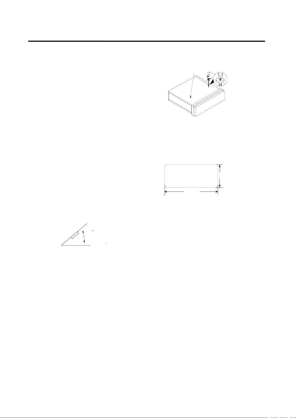
If installation angel exceeds 30
°
from
horizontal, the unit might not give its
optimum performance.
�
Avoid installing the unit where it would be
subject to high temperature, such as from
direct sunlight, or from hot air, from the
heater, or where it would be subject to
dust, dirt or excessive vibration.
DIN
DIN
DIN
DIN FRONT/REAR-MOUNT
FRONT/REAR-MOUNT
FRONT/REAR-MOUNT
FRONT/REAR-MOUNT
This unit can be properly installed either
from “ Front ” (conventional DIN Front-mount)
or “ Rear ” (DIN Rear-mount installation,
utilizing threaded screw holes at the sides
of the unit chassis). For details, refer to the
following illustrated installation methods.
DIN
DIN
DIN
DIN FRONT-MOUNT
FRONT-MOUNT
FRONT-MOUNT
FRONT-MOUNT (Method
(Method
(Method
(Method A)
A)
A)
A)
Installation
Installation
Installation
Installation Opening
Opening
Opening
Opening
This unit can be installed in any dashboard
having an opening as show n below:
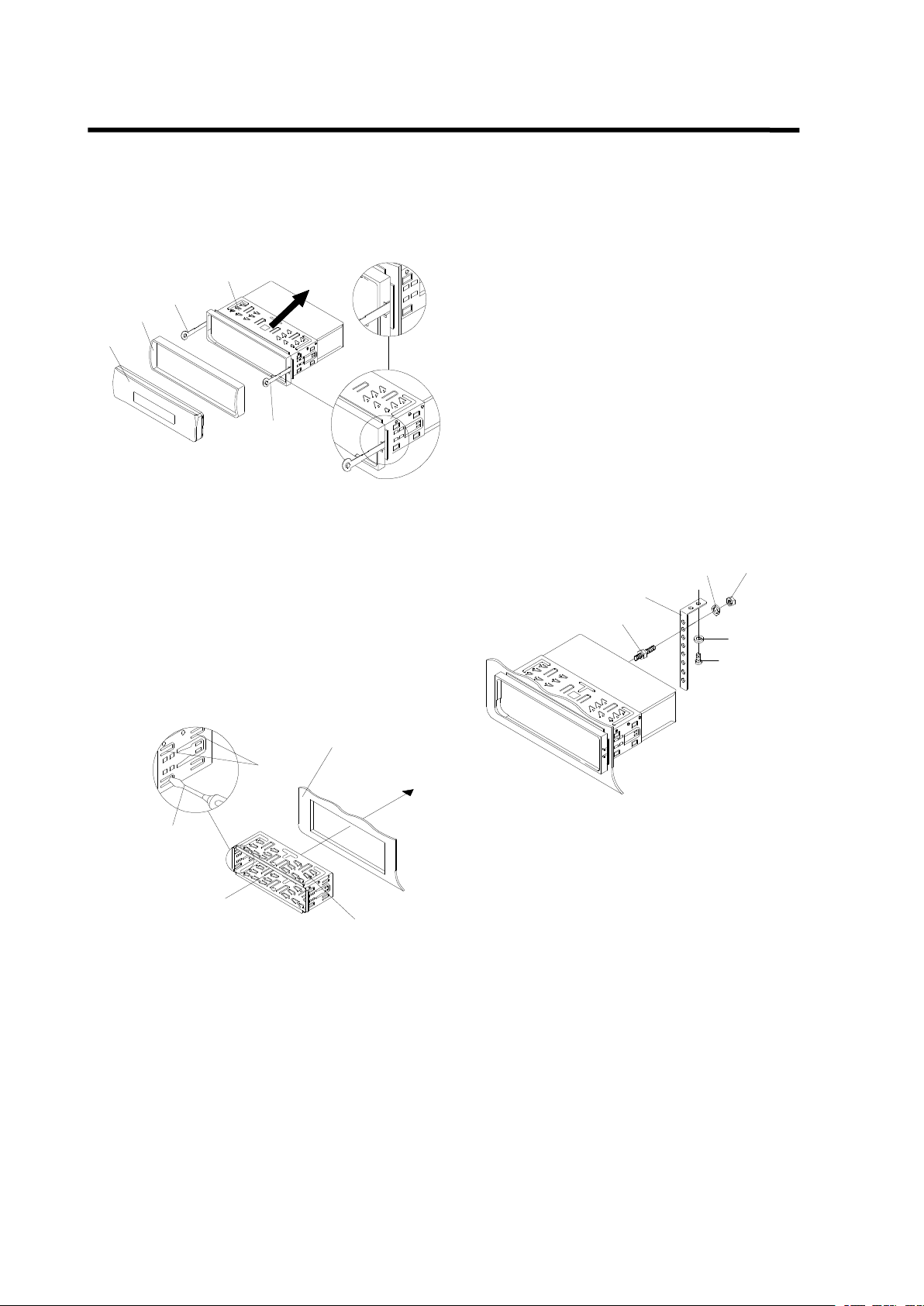
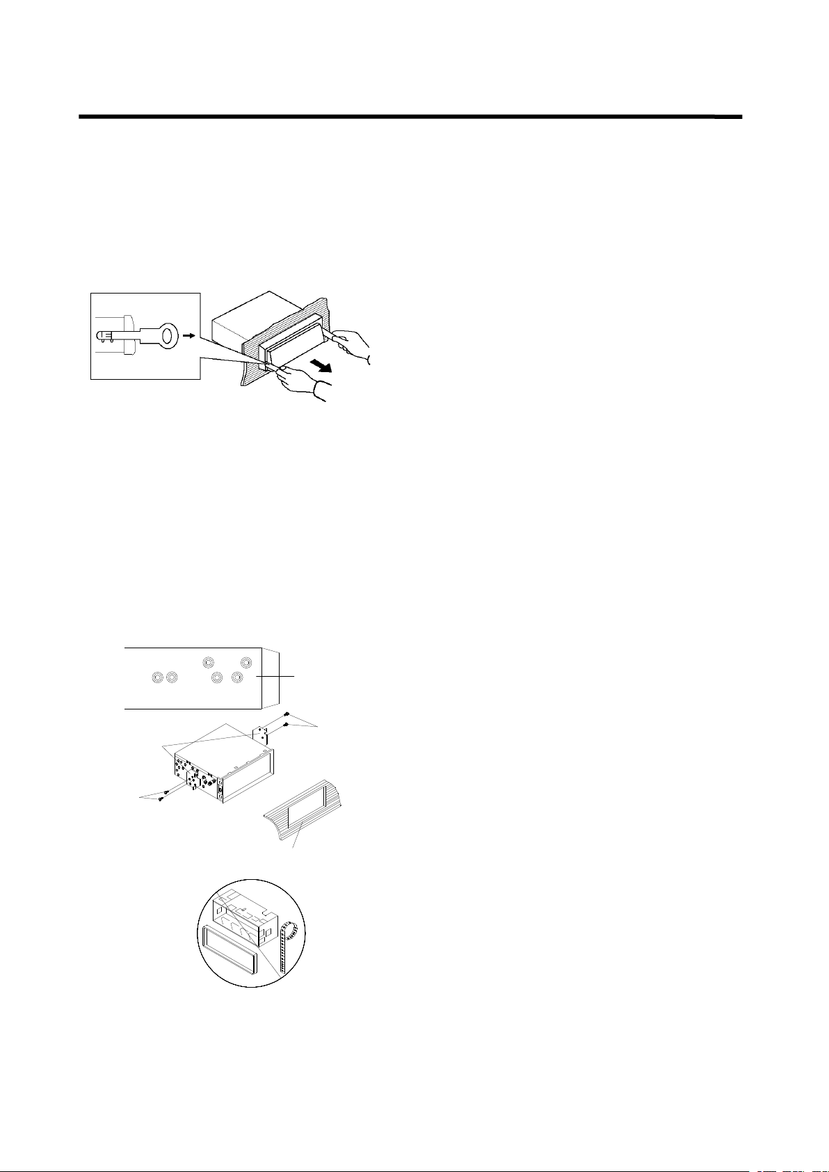
Installing
Installing
Installing
Installing the
the
the
the unit
unit
unit
unit
Be sure you test all connections first, and
then follow these steps to install the unit.
1. Make sure the ignition is turned off, and
then d isconnect the cable from the
vehicle battery
’
s negative (-) terminal.
2. Disconnect the wire harness and the
antenna.
3. Press the release button on the front
panel and remove the control panel
(see the steps of “ removing the front
panel ” ).
4. Lift the top of the outer trim ring then pull
it out to remove it.
5. The two supplied keys release tabs inside
the unit s sleeve so you can remove it.
Insert the keys as far as
30
53mm
182mm
Take out screw
before installation.
4
INSTALLATION
INSTALLATION
INSTALLATION
INSTALLATION
they will go (with the notches facing up) into
the appropriate slots at the middle left and
right sides of the unit. Then slide the sleeve
off the back of the unit.
6. Mount the sleeve by inserting the sleeve
into the opening of the dashboard and
bend open the tabs located around the
sleeve with a screwdriver. Not all tabs will
be able to make contact, so examine
which ones will be most effective . Bending
open the appropriate tabs behind the
dashboard to secure the sleeve in place.
Tabs
Screwdriver
Sleeve
Dashboard
7. Reconnect the wire harness and the
antenna and be careful not to pinch any
wires or cables.
8. Slide the unit into the sleeve until it locks
into place.
9. To further secure the unit, use the supplied
metal strap to secure the
back of the unit in place. Use the supplied
hardware (Hex Nut ( M 5mm) and Spring
Washer) to attach one end of the strap to
the mounting bolt on the back of the unit. If
necessary, bend the metal strap to fit your
vehicle s mounting area. Then use the
supplied hardware (Tapping Screw
(5x25mm) and Plain Washer) to attach the
other end of metal strap to a solid metal part
of the vehicle under the dashboard. This
strap also helps ensure proper electrical
grounding of the unit.
Note to install the short threading terminal of
the mounting bolt to the back of the unit and
the other long threading terminal to the
dashboard .
Mounting Bolt
Spring Washer
Plain Washer
Tapping Screw
Hex Nut
Metal Strap
10. Reconnect the cable to the vehicle
battery s negative (-) terminal. Then replace
the outer trim ring and install the unit s front
panel (see the steps of installing the front
panel ).
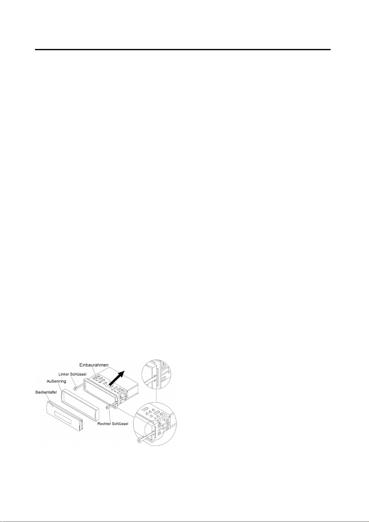
Removing
Removing
Removing
Removing the
the
the
the unit
unit
unit
unit
1. Make sure the ignition is turned off, then
d isconnect the cable from the vehicle
battery s negative (-) terminal.
2. Remove the metal strap attached the back
of the unit (if attached).
3. Press the release button to remove the front
panel.
Outer Trim Ring
Front Panel
L Key
Sleeve
R Key
5
INSTALLATION
INSTALLATION
INSTALLATION
INSTALLATION
4. Lift the top of the outer trim ring then pull it
out to remove it.
5. Insert both of the supplied keys into the
slots at the middle left and right sides of the
unit, then pull the unit out of the dashboard.
DIN
DIN
DIN
DIN REAR-MOUNT
REAR-MOUNT
REAR-MOUNT
REAR-MOUNT (Method
(Method
(Method
(Method B)
B)
B)
B)
If your vehicle is a Nissan, Toyota, follow these
mou n ting instructions.
Use the screw holes marked T ( Toyota ), N
(Nissan) located on both sides of the unit to
fasten the unit to the factory radio mounting
brackets supplied with your vehicle.
Dashboard or Console
Screw
Factory Radio
Mounting Bracket
Side View showing
Screw Holes marked
T, N
Screw
To fasten the unit to the factory radio mounting
brackets.
Align the screw holes on the bracket with the
screw holes on the unit, and then tighten the
screws (5x5mm ) on each side.
Note: the outer trim ring, sleeve and the metal
strap are not used for method B installation.
6
To
To
To
To
Detach
Detach
Detach
Detach the
the
the
the Front
Front
Front
Front Panel
Panel
Panel
Panel
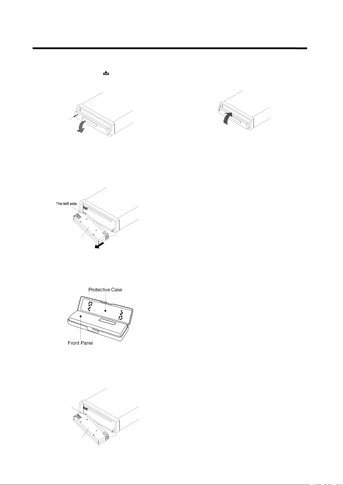
1. Press the release ( ) button, then the
front panel will be folded down.
OPEN
2.
To
r emove the front panel , lift it up at a
little angle from horizontal position, then
first pull out the right side and then pull
out the left side.
Front Panel
The right side
3. For safekeeping, store the front panel in
the supplied protective case immediately
after being removed.
To
To
To
To
I
I
I
I nstall
nstall
nstall
nstall the
the
the
the Front
Front
Front
Front Panel
Panel
Panel
Panel
1.
To
install the front panel , first insert the
left side into proper position then insert
the right side into place .
The left side
Front Panel
The right side
2. When the two sides fixed into place,
push the front panel into main unit.
3. Note that if the front panel fails to lock in
position properly, press ing control button
may not function and the display may be
missing some segments. Press the
release button and then reinstall the front
panel again.
Precautions
Precautions
Precautions
Precautions when
when
when
when handling
handling
handling
handling
1. Do not drop the front panel.
2. Do not put pressure on the display or
control buttons when detaching or
re-installing the front panel.
3. Do not touch the contacts on the front
panel or on the main unit body. It may
result in poor electrical contact.
4. If any dirt or foreign substances
adhered on the contacts, they can be
removed with a clean and dry cloth.
5. Do not expose the front panel to high
temperatures or direct sunlight in
anywhere.
6. Keep away any volatile agents (e.g.
benzene, thinner, or insecticides) from
touching the surface of the front panel
7. Do not attempt to disassemble the front
panel.
USING
USING
USING
USING THE
THE
THE
THE DETACHABLE
DETACHABLE
DETACHABLE
DETACHABLE FRONT
FRONT
FRONT
FRONT PANEL
PANEL
PANEL
PANEL
7
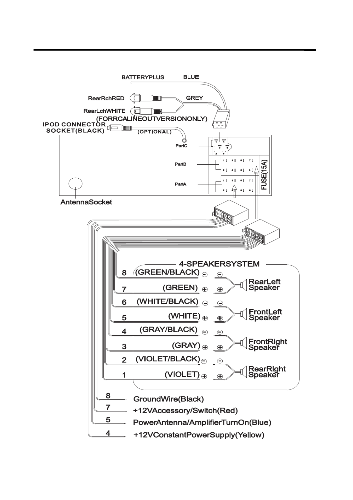
WIRING
WIRING
WIRING
WIRING CONNECTION
CONNECTION
CONNECTION
CONNECTION
ISO
ISO
ISO
ISO CONNECTION
CONNECTION
CONNECTION
CONNECTION
8
OPERATION
OPERATION
OPERATION
OPERATION
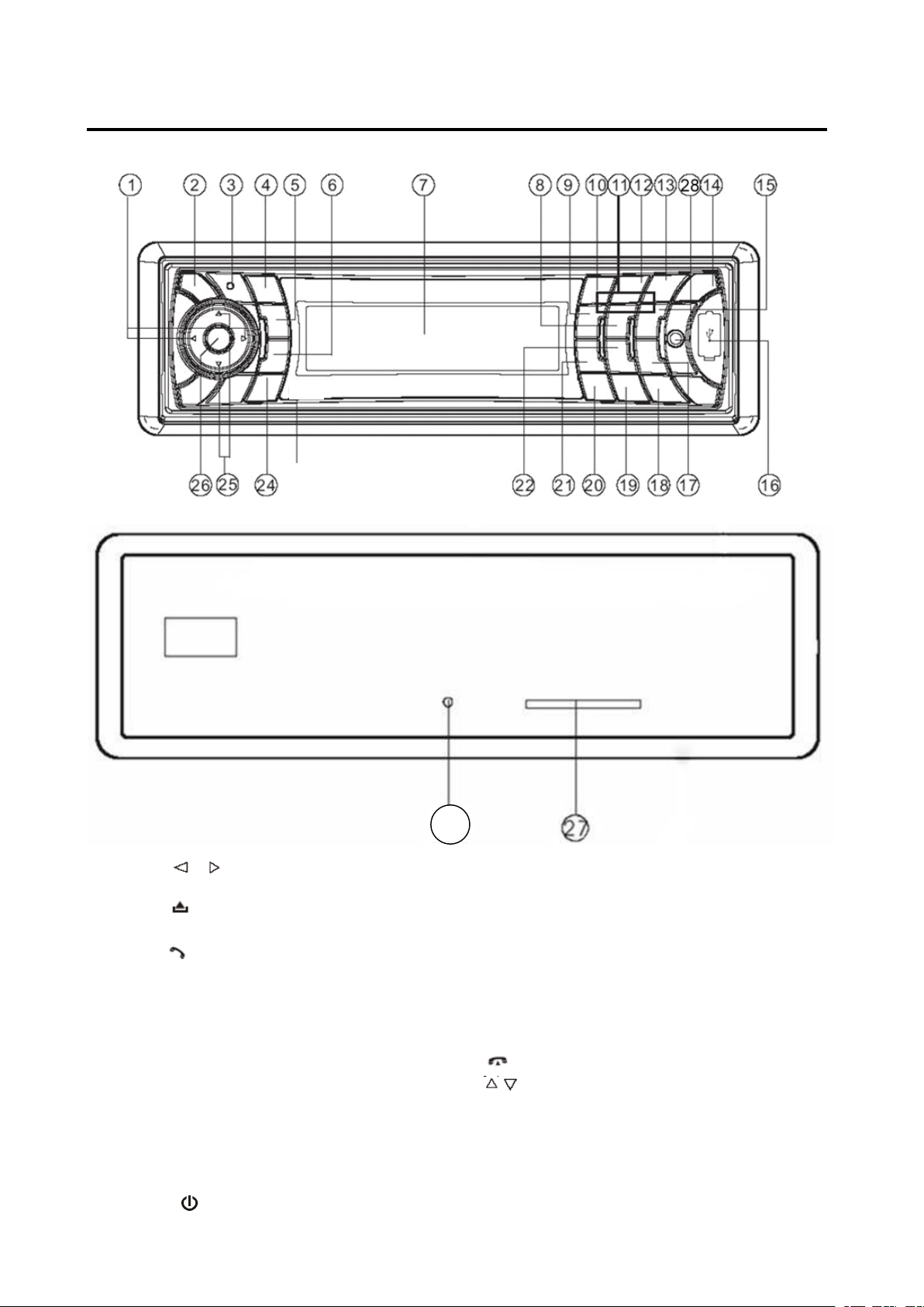
LOCATION
LOCATION
LOCATION
LOCATION OF
OF
OF
OF KEYS
KEYS
KEYS
KEYS
1. / (tune/seek/track down/up
buttons)
2. ( release button )
3. Mic
4. ( pick up )
5.PAIR/ MOD
6. T-MENU /TRANSFER
7. LCD
8. 5 DIR-
9. 4 SHF
10. 1 PAU
11. 1-6 preset buttons
12. 2 SCN
13. 3 RPT
14. / MUTE
15. 6 DIR+
16.USB interface
17.9 PTY
18. SCAN /RE-CON
19.0 DSP
20. AS/PS/*/+/Navi-SCH
21.7 AF
22.8 EQ/TA
23. .reset button
24 . (hang up) / BND/LOUD / CLR
25. / (volume up/down buttons)
26.SEL/MENU
27.SD/MMC interface
28. AUX IN
23

9
OPERATION
OPERATION
OPERATION
OPERATION
BASIC
BASIC
BASIC
BASIC OPERATION
OPERATION
OPERATION
OPERATION
SWITCHING
SWITCHING
SWITCHING
SWITCHING ON/OFF
ON/OFF
ON/OFF
ON/OFF THE
THE
THE
THE UNIT
UNIT
UNIT
UNIT
P ress button ( 14 ) to turn on the unit.
When the unit is on, press and hold
button (1 4 ) to turn the unit off .
FACEPLATE
FACEPLATE
FACEPLATE
FACEPLATE RELEASE
RELEASE
RELEASE
RELEASE
Press button ( 2 ) to detach the
removable faceplate.
SOUND
SOUND
SOUND
SOUND ADJUSTMENT
ADJUSTMENT
ADJUSTMENT
ADJUSTMENT
Shortly p ress SEL
SEL
SEL
SEL /MENU
/MENU
/MENU
/MENU button ( 26 ) to
enter AUDIO SETTING mode, use
SEL
SEL
SEL
SEL /MENU
/MENU
/MENU
/MENU button (26) or / (1) to
select the desired adjustment mode. The
adjustment mode will change in the
following order:
Bass / Treble / Balance / Fader /Sub-woof/ON/
OF (Exit)
Shortly press / (25) to adjust the sound
quality up or down step by step, press and
hold / (25) will change the sound quality
continuously.
Shortly press MUTE
MUTE
MUTE
MUTE button (14) will mute
the sound, press it again will resume the
sound.
LOUDNESS
LOUDNESS
LOUDNESS
LOUDNESS
Press LO
LO
LO
LO UD
UD
UD
UD button ( 24 ) for several
seconds to switch loudness function on,
and “ LOUD ” will appear on the LCD. Press
it for several seconds again to release this
function , and “ LOUD ” will disappear.
DISPLAY
DISPLAY
DISPLAY
DISPLAY
Press DSP
DSP
DSP
DSP button (19) to change display
mode.
EQUALIZATION
EQUALIZATION
EQUALIZATION
EQUALIZATION
Press E
E
E
E Q
Q
Q
Q button ( 22 ) shortly to turn on
equalization function and to select desired
audio mode. There are five kinds of mode
as below:
FLAT → CLAS → POP M → ROCK → DSP OFF
RESET
RESET
RESET
RESET FUNCTION
FUNCTION
FUNCTION
FUNCTION
RESET
RESET
RESET
RESET button ( 23 ) must be activated with
either a ballpoint pen or thin metal object.
The RESET
RESET
RESET
RESET button is to be activated for the
following reasons:
- Initial installation of the unit when all
w i ri ng is completed.
- All the function buttons do not operate.
- Error symbol on the display.
Note: if press RESET
RESET
RESET
RESET button ( 23 ), the unit
can ’ t work yet, please use a cotton swab
soaked in isopropyl alcohol to clean the
socket on the front panel.
MODE
MODE
MODE
MODE SELECTION
SELECTION
SELECTION
SELECTION
Shortly press MOD
MOD
MOD
MOD button (5) to change the
mode among: Radio, CD, USB, CARD,
IPOD (optional), AUX and BT Audio.
SYSTEM
SYSTEM
SYSTEM
SYSTEM SETTING
SETTING
SETTING
SETTING
Press and hold MENU
MENU
MENU
MENU button (26) on the
front panel to enter SYSTEM SETTING
mode. There are below items for you to
adjust.
BEEP / P-VOL / AREA / HOUR 24H / PCLK
Use SEL
SEL
SEL
SEL button (26) or / (1) to select
the item you want to change, and use
/ (25) to change the corresponding
setting.
1) BEEP: ON/OFF
To
turn the beep sound on/off when
pressing the buttons on the front panel
2) P-VOL Select
P-VOL: The max volume value when you
turn on the unit. Such as when you set
the P-VOL to 4 0. If the volume value is
small than 4 0 when you turn off the unit.
Next time you turn on the unit. The
volume will keep the last volume value.
But if the volume value is large than 4 0
when you turn off the unit. Then next time
you turn on the unit. The volume value
will back to 4 0.
3) Area: Use / (25) button.
You
can

10
OPERATION
OPERATION
OPERATION
OPERATION
set the radio frequency to Europe
frequency or USA frequency.
4) HOUR 24/12
You
can select time format to 12 hour or
24 hour format. (In AREA item. When you
change the radio frequency to the EUR.
The time format will be changed to 24
HOUR format automatically. When you
change the radio frequency to the USA.
The time format will be change to 12
HOUR format automatically.)
5) PCLK ON/OFF: no function.
AUXILIARY
AUXILIARY
AUXILIARY
AUXILIARY INPUT
INPUT
INPUT
INPUT
The unit can be connected to a portable
audio player through the AUX
AUX
AUX
AUX IN
IN
IN
IN jack (30)
on the front panel. A fter finishing the
connection, you can press MOD
MOD
MOD
MOD button (5)
on the front panel to switch the mode to
AUX IN mode.
RADIO
RADIO
RADIO
RADIO OPERATION
OPERATION
OPERATION
OPERATION
SELECTING
SELECTING
SELECTING
SELECTING THE
THE
THE
THE FREQUENCY
FREQUENCY
FREQUENCY
FREQUENCY BAND
BAND
BAND
BAND
At radio mode, press BND
BND
BND
BND button ( 24 )
shortly to select the desired band.
The reception band will change in the
following order:
FM1 / FM2 / FM3 / AM
SELECTING
SELECTING
SELECTING
SELECTING STATION
STATION
STATION
STATION
Shortly press / buttons (1) to activate
automatic seek function. Press for several
seconds until “ MANUAL ……” appears on
the display, the manual tuning mode is
selected. If both buttons have not been
pressed for several seconds, they will
return to seek tuning mode and
“ AUTO ……” appears on the display.
AUTOMATIC
AUTOMATIC
AUTOMATIC
AUTOMATIC MEMORY
MEMORY
MEMORY
MEMORY STORING
STORING
STORING
STORING &
&
&
&
PROGRAM
PROGRAM
PROGRAM
PROGRAM SCANNING
SCANNING
SCANNING
SCANNING
- Automatic memory storing
Press AS/PS
AS/PS
AS/PS
AS/PS button (20) for several
seconds “ SEARCH ” will appear on LCD.
the radio will search from the current
frequency and checks the signal
strength until one cycle search is
finished. And then 6 strongest stations
are stored into the corresponding preset
number button.
- Program scanning
Press A
A
A
A S/PS
S/PS
S/PS
S/PS button ( 20 ) shortly to scan
preset station. A nd the corresponding
station number P1~P6 will flash on LCD.
S
S
S
S CAN
CAN
CAN
CAN
Press SCAN
SCAN
SCAN
SCAN button (18) to enter scan
mode, the unit will scan to higher frequency
station and keep on each station for several
seconds (the corresponding frequency will
flash 5 times on LCD).
STATION
STATION
STATION
STATION STORING
STORING
STORING
STORING
Searched a station p ress preset button (1-6)
for several seconds (until 2 ’ nd beeps come
out), current station is stored into the
number button.
RDS
RDS
RDS
RDS (RADIO
(RADIO
(RADIO
(RADIO
DATA
DATA
DATA
DATA
SYSTEM)
SYSTEM)
SYSTEM)
SYSTEM)
OPERATION
OPERATION
OPERATION
OPERATION
- Setting RDS mode
Press AF
AF
AF
AF button ( 21) and release
immediately to switch on or off RDS
mode.
Whenever RDS is switch on, “ RDS ” will
flash on LCD.
- USE PT
PT
PT
PT Y
Y
Y
Y BUTTON (17)
1) Shortly press PTY
PTY
PTY
PTY button ( 17 ) will
enter PTY SELECT mode, the
program name will be displayed on
the LCD, you can use / (25) to
select the items and press /
button s ( 1 ) to begin search the
corresponding program.
2) Press and hold PTY
PTY
PTY
PTY button (17) will
enter RDS MENU, in the menu, use
/ (25) to select the items and
press / button s ( 1 ) to adjust
corresponding item.
There are below items for you to
adjusting:
11
OPERATION
OPERATION
OPERATION
OPERATION
TA
/ PI / RETURN / MASK / EONTA /
TAVOL
/ REG
TA:
TA:
TA:
TA: SEEK/ALARM
a)
TA
SEEK mode:
When newly tuned station does not
receive TP information for 5
seconds, the radio retunes to next
station which has not the same
station (PI) as the last station, but
has the TP information.
When TP information gets lost at the
current station for retune time which
is set by RETUNE SHORT or
RETUNE LONG, the radio start to
retune to next same PI station.
W hen PI station does not catch in
one cyclic search, the radio retunes
to next station with TP information.
Note: In
TA
SEEK mode, the current
station can be changed to the
completely different station because
the unit searches TP station when
the field (signal) strength of the
current station is very weak, or the
current station has no “ TP ” signal.
(The higher priority is TP rather than
PI.)
b)
TA
ALARM mode
When this mode is selected, any
automatic retune mode is not
activated. Only double beep sound
(ALARM) is output. So, in this mode,
the unit keeps the current station
anyhow. (The PI priority is higher
than
TP.)
When newly tuned station doesn ’ t
have TP information for 5 seconds,
beeps come out. When TP
information gets lost at the current
station for retune time, the beep
sound is output.
When newly tuned station has not
RDS signal, “ PI SEEK ” is
suppressed somewhat.
PI:
PI:
PI:
PI: SOUND/MUTE:
While AF switching is implemented in
C201 station, AF can switch to 100
MHz , w hich is non genuine AF (where,
different PI with same AF) in short
“ DIP ” .
If a car cruises that critical area back
and forth, an oscillation phenomenon
can be occurred, because the different
PI code can be received from 100
MHz with “ XXX ” PI.
The car radio has special procedure to
reduce even this kind of unavoidable
situation however there is a limit to be
escaped from this serious case
perfectly.
In that serious case, 2 mode is
selectable as follows:
- PI SOUND mode:
When above different PI sound (DIP)
is heard once in a while, the DIP
’
s
sound will be heard for a short time.
- PI MUTE mode:
Under above same situation, a mute
sound will be heard for a short time.
RETUNE:
RETUNE:
RETUNE:
RETUNE: LONG/SHORT
When PI information gets lost at the
current station for retune time which
is set by RETUNE SHORT (30 sec.)
or RETUNE LONG (90 sec.), the
radio start to retune to next same PI
station.
MASK:
MASK:
MASK:
MASK: DPI/ALL
MASK DPI mode: masked only the
AF which has Different PI (DPI).
MASK ALL mode: masked the AF
which has Different PI and NO RDS
signal with high field strength.
100
100
PI: C201
PI: XXX
98
90

12
OPERATION
OPERATION
OPERATION
OPERATION
EONTA:
EONTA:
EONTA:
EONTA: DX/LO (DISTANCE/LOCAL):
The purpose of this key is to reduce
unwanted EON
TA
switching, which
EON
TA
information was received from
current station and the radio switched to
that EON linked station, but no
information could not be received
because the EON linked station is
located too far from that area. So the
radio is switched back to current station
again. In above operation, a customer
listens to a wrong program or mute
sound for a while.
EON
TA
LOCAL mode
When the filed strength level of EON
linked is less than threshold level, the
radio does not switch that station, and a
customer can hardly listen to any
disturbances.
When EON
TA
LOCAL mode is selected,
“ EON
TA
LO ” on numeric display is
indicated for a few seconds.
EON
TA
DISTANCE mode
EON
TA
switch is tried to implemented
by the information of current station.
When EON
TA
DISTANCE mode is
selected, “ EON
TA
DX ” on numeric
display is indicated for a few seconds
TA-VOLUME:
TA-VOLUME:
TA-VOLUME:
TA-VOLUME: Volume 30 (the default
TA
volume value is 30, you can adjust it
from 0 to 100).
REG
REG
REG
REG (REGION) :
:
:
: OFF/ON
REGION ON mode: AF switching or PI
SEEK is implemented to the station
which have all PI codes are the same as
current station.
REGION OFF mode: The regional code
in the format of PI code is ignored when
AF switching or PI SEEK is
implemented.
-
-
-
- Listening
Listening
Listening
Listening to
to
to
to Traffic
Traffic
Traffic
Traffic Announcement
Announcement
Announcement
Announcement
TA
TA
TA
TA
button ( 22 ) is operated as follows:
When pressed and held for several
seconds , it is engaging whether
TA
TA
TA
TA
mode on or off.
When
TA
TA
TA
TA
mode, is on and a traffic
announcement is transmitted:
When the unit was in CD (MP3) mode
or AUX IN mode or IPOD mode , it will
switch temporarily to radio mode.
Temporary switch over to an EON linked
station when EON detects a traffic
announcement on that other program.
If the volume level was under the
threshold point it will be raised to the
threshold point. But the user changed
the volume level, which was more than
the threshold point (min.
TA
TA
TA
TA
volume
level), it will be set to the last level.
When
TA
TA
TA
TA
mode is on,
TA
TA
TA
TA
of individual
segment is turned on.
When a TP station is received, TP of
individual segment is turned on.
TA
TA
TA
TA
interruption function
The current traffic announcement is
cancelled by pressing this key.
But the
TA
TA
TA
TA
mode will not be off.
The RDS data used are the PI, PS,
AF,
TP,
TA, EON and PTY data.
PI: Program Identification code
Code for identifying programs
PS: Program Service Name
Broadcast station name data
expressed in alphanumerically
characters
AF: Alternative Frequencies
Frequency list of broadcasting
stations transmitting the same
program
TP: Traffic Program Identification
Identification data for traffic
information-broadcasting station
TA: Traffic Announcement Identification
Identification data showing traffic
information is being transmitted or
not

13
OPERATION
OPERATION
OPERATION
OPERATION
EON: Enhanced O ther N etworks
Information
Broadcasting information on PI,
AF,
TP,
TA, etc, relating to networks
other than the network used for
current reception
PTY: Program Type Code
Contents of programs such as
news, light music, sports etc.
USB
USB
USB
USB PLAY
PLAY
PLAY
PLAY OPERATION
OPERATION
OPERATION
OPERATION
SWITCH
SWITCH
SWITCH
SWITCH TO
TO
TO
TO USB
USB
USB
USB MODE
MODE
MODE
MODE
In the front panel of the unit, there is an
USB interface ( 16 ).
You
can connect an
USB driver through this interface ( 16 ).
W hen you connect a n USB driver through
the interface, the unit will search the MP3
files or WMA files in the USB driver and
start to play MP3 files or WMA files
automatically.
I f in other mode, you can also press MOD
MOD
MOD
MOD
button (5) to select USB mode.
SELECT
SELECT
SELECT
SELECT ING
ING
ING
ING TRACKS
TRACKS
TRACKS
TRACKS
P ress / (1) will skip to the
previous /next file . File number will be
show ed on display.
Press and h old / (1) will fast
reverse / forward. File play starts when you
release the button.
PAUSING
PAUSING
PAUSING
PAUSING PLAYING
PLAYING
PLAYING
PLAYING
Press PAU
PAU
PAU
PAU button ( 10 ) to pause , and
“ Pause ” will appear on LCD.
Press it again to resume play , and “ Pause ”
will disappear.
PREVIEW
PREVIEW
PREVIEW
PREVIEW ING
ING
ING
ING ALL
ALL
ALL
ALL TRACKS
TRACKS
TRACKS
TRACKS
P ress SCN
SCN
SCN
SCN button ( 12 ) to play first several
seconds of each file, and “ Scan ” will appear
on LCD. Press again to stop intro and listen
to file, “ Scan ” will disappear.
Press and hold SCN
SCN
SCN
SCN button (12) will play
first several seconds of each file in the
current folder, and “ D-SCN ” will appear,
press it again will exit this mode.
REPEAT
REPEAT
REPEAT
REPEAT ING
ING
ING
ING THE
THE
THE
THE SAME
SAME
SAME
SAME TRACK
TRACK
TRACK
TRACK
P ress RPT
RPT
RPT
RPT button ( 13 ) to continuously
repeat the same file, and “ S-RPT ” will
appear on LCD. Press it again to stop
repeat , and “ S-RPT ” will disappear.
Press and hold RPT
RPT
RPT
RPT button (13) will repeat
all the files in the current folder. A nd
“ D-RPT ” will appear on LCD. P ress it again
will exit this mode.
PLA
PLA
PLA
PLA YING
YING
YING
YING ALL
ALL
ALL
ALL TRACKS
TRACKS
TRACKS
TRACKS IN
IN
IN
IN RANDOM
RANDOM
RANDOM
RANDOM
P ress SHF
SHF
SHF
SHF button ( 9 ) to play all file s on CD
in random order , and “ S-SHF ” will appear
on LCD. Press again to cancel the function ,
and “ S-SHF ” will disappear.
Press and hold SHF
SHF
SHF
SHF button (9) for 2
seconds will play all files (in the current
folder) in random order. A nd “ S-SHF ” will
appear on LCD. P ress it again will exit this
mode.
SELECTING
SELECTING
SELECTING
SELECTING DIRECTORY
DIRECTORY
DIRECTORY
DIRECTORY UP/DOWN
UP/DOWN
UP/DOWN
UP/DOWN
Press DIR-
DIR-
DIR-
DIR- button (8) or DIR+
DIR+
DIR+
DIR+ button
(15) to select directory downward or
upward. If the USB driver does not
contain any directory, there is no
function of pressing DIR-
DIR-
DIR-
DIR- button (8) or
DIR+
DIR+
DIR+
DIR+ button (15).
SELECT
SELECT
SELECT
SELECT ING
ING
ING
ING TRACKS
TRACKS
TRACKS
TRACKS
Searching
Searching
Searching
Searching Track
Track
Track
Track Directly
Directly
Directly
Directly
Press A
A
A
A S/PS
S/PS
S/PS
S/PS (
(
(
( Navi-SCH
Navi-SCH
Navi-SCH
Navi-SCH )
)
)
) button (20) for
one time. It enters into “ Searching track
directly ” mode .
The unit searches the track selected by
following direct numeric buttons:
M1-M6,
M1-M6,
M1-M6,
M1-M6, MOD
MOD
MOD
MOD (
(
(
( 5
5
5
5 ),
),
),
), TUNE/SEEK/TRACK
TUNE/SEEK/TRACK
TUNE/SEEK/TRACK
TUNE/SEEK/TRACK
DOWN
DOWN
DOWN
DOWN (8),
(8),
(8),
(8), TUNE/SEEK/TRACK
TUNE/SEEK/TRACK
TUNE/SEEK/TRACK
TUNE/SEEK/TRACK UP
UP
UP
UP (9),
(9),
(9),
(9),
DSP(0).
DSP(0).
DSP(0).
DSP(0).
If selected three digits, the unit searches
the tract at once. If selected one or two
digits, the unit wait for BND/LOU
BND/LOU
BND/LOU
BND/LOU /ENT
/ENT
/ENT
/ENT
button for seconds. The unit searches
the track after few seconds, even if the

14
OPERATION
OPERATION
OPERATION
OPERATION
enter button is not pressed.
Searching
Searching
Searching
Searching Directory
Directory
Directory
Directory or
or
or
or File
File
File
File Name
Name
Name
Name
Press A
A
A
A S/PS
S/PS
S/PS
S/PS (
(
(
( Navi-SCH
Navi-SCH
Navi-SCH
Navi-SCH )
)
)
) button (20) for
two times. It enters into “ Searching
Directory or File Name ” mode .
The unit searches files and directories
that have the same character which is
inputted by the user pressing the
corresponding buttons listed on the
Table below .
AS/PS Mode Select
BND/LOU ENTER
M1 A, B, C, 1
M2 D, E,
F,
2
M3 G, H, I, 3
M4 J, K, L, 4
M5
M, N, O, 5/Directory
DOWN
M6
P,
Q, R, 6/Directory UP
MOD S,
T,
U, 7
TUNE/SEEK/TRACK
DOWN
V,
W, X, 8
TUNE/SEEK/TRACK
UP
Y,
Z, SPACE, 9
PUSH SEL
CHARACTER SHIFT
RIGHT
DSP _,-,+,0
Explain as follows:
- Use the corresponding buttons to
select the characters
A
to Z,
blank,
0
to 9,
_, -,
+ .
- Press SEL
SEL
SEL
SEL button (26) to confirm
entry of each characters .
- Press B
B
B
B ND/LOU
ND/LOU
ND/LOU
ND/LOU /
/
/
/ ENT
ENT
ENT
ENT button (24)
to start the title search.
In case the selected title is a
directory name, display will show ( ‘ ‘ ),
then
- Use the TUNE/SEEK/TRACK
TUNE/SEEK/TRACK
TUNE/SEEK/TRACK
TUNE/SEEK/TRACK
UP/DOWN
UP/DOWN
UP/DOWN
UP/DOWN buttons to list all songs
under this directory and select the
title.
- Press B
B
B
B ND/LOU
ND/LOU
ND/LOU
ND/LOU /
/
/
/ ENT
ENT
ENT
ENT button to
confirm and start the play .
- Repeat the above steps if the newly
selected title is again a directory.
Searching
Searching
Searching
Searching From
From
From
From Root
Root
Root
Root Directory
Directory
Directory
Directory
Press A
A
A
A S/PS
S/PS
S/PS
S/PS (
(
(
( Navi-SCH
Navi-SCH
Navi-SCH
Navi-SCH )
)
)
) button (20) for
three times. The unit s earch es file or
directory from root by
TUNE/SEEK/TRACK
TUNE/SEEK/TRACK
TUNE/SEEK/TRACK
TUNE/SEEK/TRACK
UP/DOWN
UP/DOWN
UP/DOWN
UP/DOWN
buttons.
(D-DIR icon turns on if the name is
directory). D isplay will list all available
directories and son gs. Select the
desired directory / songs by using
TUNE/SEEK/TRACK
TUNE/SEEK/TRACK
TUNE/SEEK/TRACK
TUNE/SEEK/TRACK
UP/DOWN
UP/DOWN
UP/DOWN
UP/DOWN
buttons
and BND/LOU/ENT
BND/LOU/ENT
BND/LOU/ENT
BND/LOU/ENT button to confirm. If
the selected title is a song, it starts to
play.
If the selected title is a directory name,
display will show ( ‘ ‘ ), then
- Use the TUNE/SEEK/TRACK
TUNE/SEEK/TRACK
TUNE/SEEK/TRACK
TUNE/SEEK/TRACK
UP/DOWN
UP/DOWN
UP/DOWN
UP/DOWN buttons to list all songs
under this directory and select the
title.
- Press B
B
B
B ND/LOU
ND/LOU
ND/LOU
ND/LOU /
/
/
/ ENT
ENT
ENT
ENT button to
confirm and start the play .
- Repeat the above steps if the newly
selected title is again a directory.
Searching
Searching
Searching
Searching From
From
From
From Current
Current
Current
Current Directory
Directory
Directory
Directory
Press A
A
A
A S/PS
S/PS
S/PS
S/PS (
(
(
( Navi-SCH
Navi-SCH
Navi-SCH
Navi-SCH )
)
)
) button for four
times. The unit s earch es file or directory
from current directory by
TUNE/SEEK/TRACK
TUNE/SEEK/TRACK
TUNE/SEEK/TRACK
TUNE/SEEK/TRACK
UP/DOWN
UP/DOWN
UP/DOWN
UP/DOWN
buttons.
(D-DIR icon turns on if the name is
directory). The current directory name is
displayed for a second and the currently
playing file name is displayed (selected).
The user can select the directory or file
i n the directory by TUNE/SEEK/TRACK
TUNE/SEEK/TRACK
TUNE/SEEK/TRACK
TUNE/SEEK/TRACK
UP/DOWN
UP/DOWN
UP/DOWN
UP/DOWN
buttons. The selected file can
be played by press ing BND
BND
BND
BND /
/
/
/ LOU
LOU
LOU
LOU /
/
/
/ (
(
(
( ENT
ENT
ENT
ENT )
)
)
)
button.
DISPLAY
DISPLAY
DISPLAY
DISPLAY ID3
ID3
ID3
ID3 INFORMATION
INFORMATION
INFORMATION
INFORMATION
Press ID3
ID3
ID3
ID3 button (20) to show the ID3
TAG (title, artist and album)
15
OPERATION
OPERATION
OPERATION
OPERATION
SUPPORT
SUPPORT
SUPPORT
SUPPORT MP3/WMA
MP3/WMA
MP3/WMA
MP3/WMA DECODING
DECODING
DECODING
DECODING MODE
MODE
MODE
MODE
T he main unit supports MP3/WMA
(Windows Media Audio) decoding modes
as below.
Standard
Standard
Standard
Standard
Bit
Bit
Bit
Bit Rate
Rate
Rate
Rate
(kbps)
(kbps)
(kbps)
(kbps)
Supports
Supports
Supports
Supports
Mode
Mode
Mode
Mode
MPEG1 Audio
Layer 3
(44.1kHz)
32,48,64,96,
128,192,256,
320
Stereo
Windows
Media Audio
(44.1kHz)
64,96,128,192 Stereo
The USB solution can support:
1. Folder: 500 max.
2. File: 999 max.
3. Depth of folder: 8 layers
4. Size: 2 GB
N
N
N
N ote
ote
ote
ote :
T he main unit can only support the
standard USB-memory disc which is
approved by M i crosoft.
USB MP3 player is not a standard
which means different brand name or
different models have their own
standard. S o our product cannot
support every MP3 player.
W hen connecting an MP3 player and
there has normal battery in the player
(non recha rgeable battery), you should
remove the battery from the MP3
player then connect it to the USB
interface. O therwise, it may cause
battery burst.
When in USB play mode, be sure not to
remove the USB driver from the USB
interface.
CAUTION
CAUTION
CAUTION
CAUTION
W hen there are important files in the USB
device. Do not connect it to the main unit to
play. B ecause any wrong operation may
cause files loss. A nd our company
assumes no responsibility for this.
SD/MMC
SD/MMC
SD/MMC
SD/MMC
OPERATION
OPERATION
OPERATION
OPERATION (OPTIONAL)
(OPTIONAL)
(OPTIONAL)
(OPTIONAL)
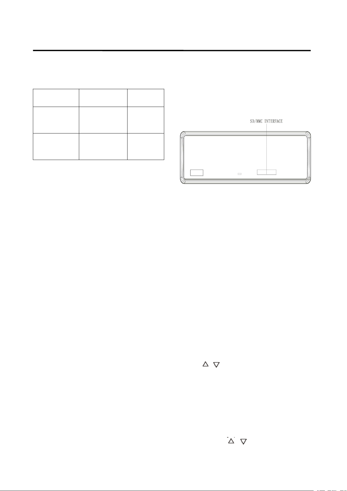
A ccording to the customer
’
s need, the unit
will add a SD/MMC interface. S ee below,
the SD/MMC interface is on the housing of
the unit.
When you insert a SD/MMC card in the
SD/MMC interface, the unit will search the
MP3 files or WMA files in the card and start
to play MP3 files or WMA files automatically.
The operation is the same with the MP3
operation described above. I f in other mode,
you can also press MOD
MOD
MOD
MOD button (5) to
select SD/MMC mode.
W hen there are important files in the
SD/MMC card , do not connect it to the main
unit to play.
IPOD
IPOD
IPOD
IPOD operation
operation
operation
operation
Select
Select
Select
Select Category
Category
Category
Category
When IPOD is playing, Press BND button
( 24 ) the category will appear on the display,
Press / (25) to change the category
among PL
A
Y LIST / ARTIST / ALBUM /
GENR E / SONG / COMPOSER, then press
SEL
SEL
SEL
SEL button ( 26 ) to confirm the selected
category.
Select
Select
Select
Select Song
Song
Song
Song
Press BND
BND
BND
BND button ( 24 ), the display will
show the current catalog (stored in the
IPOD). Press / (25) to change the
song title to the next song or the previous

16
OPERATION
OPERATION
OPERATION
OPERATION
song. Then press SEL
SEL
SEL
SEL ( 26 ) button to play
the selected song.
PAU
PAU
PAU
PAU (Pause)
(Pause)
(Pause)
(Pause)
When playing a song, press PAU
PAU
PAU
PAU button
( 10 ) will pause the playing. Press it again
will resume playing.
RPT
RPT
RPT
RPT (Repeat)
(Repeat)
(Repeat)
(Repeat)
When playing a song, press RPT
RPT
RPT
RPT button (12)
shortly will repeat the current song, and
“ S-RPT ” will appear on the display. Press it
again to exit this mode. Press it for about 2
seconds to repeat Album, and “ D-RPT ” will
appear on the display. Press it again to exit
this mode.
SHF
SHF
SHF
SHF (Shuffle)
(Shuffle)
(Shuffle)
(Shuffle)
When playing a song, press SHF
SHF
SHF
SHF button (8)
shortly, after the current song play to the
end, It will play the song in current category
in random order, and “ S HF ” will appear on
the display. Press it again to exit this mode.
Press it for 2 seconds to play all songs in
the album and “ D -S HF ” will appear on the
display Press it again to exit this mode .
TUNE/TRACK
TUNE/TRACK
TUNE/TRACK
TUNE/TRACK UP/DOWN
UP/DOWN
UP/DOWN
UP/DOWN
When playing a song, press / button
( 1 ) will play the previous/ next track in the
current category, but you can not enter to
the next category.
When playing a song more than 3 second,
press will play the song from the start
position.
When playing a song less than 3 second,
press will play the previous track.
When playing a song, press ad hold /
button ( 1 ) for several seconds will fast
reverse / forward of the playing. And the
display will show the playing time (e.g.
1 ’ 2 0).
BLUETOOTH
BLUETOOTH
BLUETOOTH
BLUETOOTH
OPERATION
OPERATION
OPERATION
OPERATION
PREPAIR
PREPAIR
PREPAIR
PREPAIR FOR
FOR
FOR
FOR BLUETOOTH
BLUETOOTH
BLUETOOTH
BLUETOOTH
OPERATION
OPERATION
OPERATION
OPERATION
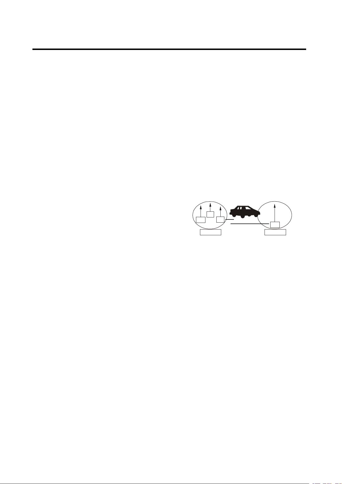
(i) When use Bluetooth, please make
sure the mobile phone supports
Bluetooth function.
(ii) For the different kind of mobile
phone, Bluetooth emissive power has
some difference.
To
get the best
conversation quality, it is commended
that the distance between the mobile
phone and the unit is within 3m. And
please don ’ t put any metal object or
any obstacle between the path of the
mobile phone and the unit.
PAIRING
PAIRING
PAIRING
PAIRING
1) In any mode, press and hold
PAIR(MOD)
PAIR(MOD)
PAIR(MOD)
PAIR(MOD) button (5) on the front
panel, “ PAIRING ” will appear on the
LCD.
2) On the mobile phone, select the
Bluetooth set up. (Please refer to the
instruction manual of your mobile
phone on how to operate Bluetooth.)
3) “ CARBT ” should appear in the list on
your mobile phone, please select
“ CARBT ” and then input password
“ 0000 ” .
4) When successful paired, “ CONN
OK! ” will be displayed on LCD.
5) When pairing failed, “ PAIR END ” will
be displayed on LCD.
You
can press
and hold PAIR button (5) again to try
the pairing again.
6) Note:
During Pairing, MODE key will no
functional during pairing mode. When
pairing, you can press and hold PAIR
PAIR
PAIR
PAIR
button (5) to terminate the pairing.

17
OPERATION
OPERATION
OPERATION
OPERATION
CONNECT
CONNECT
CONNECT
CONNECT
This unit is built-in auto-reconnection
function. Every time when you short
press button (4), the unit will auto
reconnect with the mobile phone (note:
the mobile phone must have been
paired with the unit before.).
In the following conditions you can
reconnect manually by pressing
RECON
RECON
RECON
RECON button (1 8 ) for several
seconds, when reconnect is
successful “ Conn OK! ” will be
displayed.
1) If the mobile phone is out of range,
the connection will be lost, when you
come back to the unit, reconnection is
necessary .
2) When the mobile phone is out of
range from the unit, and there is an
incoming call, when you come back to
the unit, and you want to transfer the
audio to the unit, you need to
reconnection.
3) When you press button (2) to
release the front panel, the connection
will be break off. W hen you install the
front panel, you need to reconnection.
4) If you turn off the mobile phone that
has paired with the unit, when you
turn on the mobile phone, you need to
reconnection.
T-MENU
T-MENU
T-MENU
T-MENU
When successful paired, shortly press
T-MENU
T-MENU
T-MENU
T-MENU button (6) on the front panel
will enter the telephone menu, keep
pressing this button or press /
button ( 1 ) to change the items in this
menu. The items will be displayed in
the following sequence:
PRE NUM / RECELVED / DIALED /
MISSED / MANUANS / TALK.
T he details please see the following
instruction.
1) PRE NUM:
You
can save 10
phone-call to the phonebook. In PRE
NUM mode. Press / button (25)
to select the NUMBER. Then press
SEL button, and enter the phone
number. Then press SEL button again
to save it to phonebook.
2) RECELVED: Display the last call
you have received.
3) DIALED: Display the last dialed
number.
4) MISSED: Display the call you have
missed.
5) MANU ANS
(
manual answer
)
You
can set Answer mode to manual
answer (MANU ANS) mode or Auto
Answer (AUTO ANS) mode.
I n auto answer mode, when a call
coming the Phone Number will
appear on LCD. The unit will answer
the call automatically.
In MANU
MANU
MANU
MANU ANS
ANS
ANS
ANS mode, When a call
coming, the Phone Number will
appear on LCD. you can press
button (4) to answer the call, or press
button (24) to reject the incoming
call.
6) TALK (00~20)
You
can set the bluetooth volume in
TALK item. If it is 00, When a call
coming. T he main volume will be set
to 60 automatically. If you set the
TALK volume to 20. The main volume
will be set to 100 automatically when
a call coming.

18
OPERATION
OPERATION
OPERATION
OPERATION
E xample:
TALK volume MAIN volume
00 = 60
01 = 62
02 = 64
…………………… ..
20 = 100
MAKING
MAKING
MAKING
MAKING AN
AN
AN
AN OUTGOING
OUTGOING
OUTGOING
OUTGOING CALL
CALL
CALL
CALL
1) Making an outgoing call from
SPEED DIAL, RECEIVED LIST,
DIALED LIST, MISSED LIST, PHONE
BOOK(Mobile Phone) and PHONE
BOOK (SIM Card) please refer to the
T-MENU
T-MENU
T-MENU
T-MENU section.
2) Making an outgoing call by inputting
the phone number manually.
Press button (4) on the front panel
“ CALL_ ” will appear on LCD. U se 0~9,
*, # buttons to enter the phone
number you want to dial. (Note:
shortly press * button will input “ * ”
character , press and hold it will input
“ + ” character ). Then press button
(4) again will call the number.
Note: if you input the wrong number
shortly press CLR
CLR
CLR
CLR button (24) to clear
it. P ress and hold CLR
CLR
CLR
CLR button (24) will
clear all numeric.
TRANSFER
TRANSFER
TRANSFER
TRANSFER THE
THE
THE
THE CALL
CALL
CALL
CALL BETWEEN
BETWEEN
BETWEEN
BETWEEN
MOBILE
MOBILE
MOBILE
MOBILE PHONE
PHONE
PHONE
PHONE AND
AND
AND
AND THE
THE
THE
THE UNIT
UNIT
UNIT
UNIT
During the talking mode, you can press
and hold TRANSFER
TRANSFER
TRANSFER
TRANSFER ( T-MENU)
T-MENU)
T-MENU)
T-MENU) button
(6) to transfer the phone call between
the mobile phone and the unit.
Note:
1) If you transfer the call to mobile
phone, the mute of the present mode
will be released at the same time.
2) When making an outgoing call, it
’
s
not possible to transfer if the call is
not being answered yet.
BT
BT
BT
BT reset
reset
reset
reset : : In BT AUDIO mode. Press
and hold BND/LOU/ key for
several seconds. Some of the
bluetooth information will be reseted
(The RECELVED / DIALED / MLSSED
information will be lost).
BLUETOOTH
BLUETOOTH
BLUETOOTH
BLUETOOTH AUDIO
AUDIO
AUDIO
AUDIO (A2DP
(A2DP
(A2DP
(A2DP
FUNCITON)
FUNCITON)
FUNCITON)
FUNCITON)
The unit support s B luetooth audio
function. I f your mobile phone can play
stereo audio, when the pairing is ok,
you can choose the unit you have
paired to play the stereo music.
M1, M2, button on the front panel of the
unit serves as PAUSE/PLAY and STOP
control button. (It is up to the mobile
phone, the different mobile phone has
the d i f fer ent define.)
Use / button ( 1 ) on the front panel
of the unit to choose the previous/next
track. (It is up to the mobile phone, the
d i f fer ent mobile phone has the d i f fer ent
define)

19
SPECIFICATION
SPECIFICATION
SPECIFICATION
SPECIFICATION
GENERAL
GENERAL
GENERAL
GENERAL
Power Supply Requirements : DC 12 Volts, Negative Ground
Chassis Dimensions : 178 (W) x 1 60 (D) x 50 (H)
Tone Controls
- Bass (at 100 Hz) : ± 10 dB
- Treble (at 10 kHz) : ± 10 dB
Maximum Output Power
- Version Y/Y1/Y2 : 4x40 watts /4X45watts/4X50watts
Current Drain
- Version Y/Y1/Y2 : 15 A mpere (max.) (For High Power
Version)
CD
CD
CD
CD PLAYER
PLAYER
PLAYER
PLAYER
Signal to Noise Ratio : More than 55 d B
C hannel Separation : More than 50 dB
Frequency Response : 40 Hz – 18 kHz
RADIO
RADIO
RADIO
RADIO
For
For
For
For 2
2
2
2 Bands
Bands
Bands
Bands
Europe)
Europe)
Europe)
Europe)
FM
FM
FM
FM
Frequency Coverage 87.5 to 10 8 MHz
IF 10.7 MHz
Sensitivity (S/N=30dB) 4 μ V
Stereo Separation > 25 dB
MW
MW
MW
MW
Frequency Coverage 5 22 to 1620 K Hz
IF 450 K Hz
Sensitivity (S/N=20dB) 36dBuV

20
TROUBLE
TROUBLE
TROUBLE
TROUBLE SHOOTING
SHOOTING
SHOOTING
SHOOTING
Before going through the checklist, check wiring connection. If any of the
problems persist after checklist has been made, consult your nearest service
dealer.
Symptom
Symptom
Symptom
Symptom Cause
Cause
Cause
Cause Solution
Solution
Solution
Solution
No power .
The car ignition switch is
not on.
If the power supply is
connected to the car accessory
circuits, but the engine is not
moving, switch the ignition key
to “ ACC ” .
The fuse is blown. Replace the fuse.
Temperature inside the car
is too high.
Cool off or until the ambient
temperature return to normal.
Condensation. Leave the player off for an hour or
so, then try again.
No sound .
Volume is in minimum Adjust volume to a desired level.
Wiring is not properly
connected.
Check wiring connection.
Sound skips .
The installation angle is
more than 30 degree.
Adjust the installation angle less
than 30 degree.
The disc is extremely
dirty or defective disc.
Clean the compact disc, then try to
play a new one.
The operation
keys do not
work .
The built-in microcomputer
is not operating properly
due to noise.
Press the RESET button.
Front panel is not properly fix into
its place.
The radio does
not Work. The
radio station
automatic
selection does
not work .
The antenna cable is not
connected.
Insert the antenna cable firmly.
The signals are too weak. Select a station manually.
CS-351
CS-351
CS-351
CS-351
BENUTZERHANDBUCH
BENUTZERHANDBUCH
BENUTZERHANDBUCH
BENUTZERHANDBUCH
Mobiles
M obiles
Mobiles
MobilesAudiosystem
A udiosystem
Audiosystem
Audiosystem
�
�
�
�Stereoradio
Stereoradio
Stereoradio
Stereoradiomit
m it
mit
mitPLL-Synthesizer
P LL-Synthesizer
PLL-Synthesizer
PLL-Synthesizer
�
�
�
�Automatisches
Automatisches
Automatisches
AutomatischesSpeichern
S peichern
Speichern
Speichernvon
v on
von
vonSendern
S endern
Sendern
Sendern
�
�
�
�RDS-Funktion
RDS-Funktion
RDS-Funktion
RDS-Funktion
�
�
�
�Elektronischer
Elektronischer
Elektronischer
ElektronischerErsch
E rsch
Ersch
Erschü
ü
ü
ütterungsschutz
t terungsschutz
tterungsschutz
tterungsschutz(ESP)
( ESP)
(ESP)
(ESP)
�
�
�
�USB-Port
USB-Port
USB-Port
USB-Port&
&
&
&SD/MMC-Kartenslot
S D/MMC-Kartenslot
SD/MMC-Kartenslot
SD/MMC-Kartenslot
�
�
�
�IPOD-Unterst
IPOD-Unterst
IPOD-Unterst
IPOD-Unterstü
ü
ü
ützung
t zung
tzung
tzung
�
�
�
�Bluetooth-Freisprechfunktion
Bluetooth-Freisprechfunktion
Bluetooth-Freisprechfunktion
Bluetooth-Freisprechfunktion&
&
&
&
A2DP-Stereo
A2DP-Stereo
A2DP-Stereo
A2DP-Stereoü
ü
ü
übertragung
b ertragung
bertragung
bertragung
�
�
�
�Faltbare,
Faltbare,
Faltbare,
Faltbare,abnehmbare
a bnehmbare
abnehmbare
abnehmbareBedientafel
B edientafel
Bedientafel
Bedientafel
�
�
�
�Aux-Eingang
Aux-Eingang
Aux-Eingang
Aux-Eingang
Zur
Z ur
Zur
ZurInformation
I nformation
Information
Informationund
u nd
und
undUnterst
U nterst
Unterst
Unterstü
ü
ü
ützung,
t zung,
tzung,
tzung,www.lenco.eu
w ww.lenco.eu
www.lenco.eu
www.lenco.eu

INHALT
INHALT
INHALT
INHALT
Einbau
Einbau
Einbau
Einbau.
.
.
..........................................................
.........................................................
.........................................................
.........................................................2
2
2
23
3
3
3
HerauschraubenderSchraubenvordem
Einbau.........................................................23
DIN-Vordereinbau(MethodeA)...............23
EinbaudesGeräts................................24
EntfernendesGeräts...........................25
DIN-Rückseiteneinbau(MethodeB)......26
Benutzung
Benutzung
Benutzung
Benutzungder
der
de r
derabnehmbaren
abne hmbaren
abnehmbaren
abnehmbarenBedientafel
Bedi entafel
Bedientafel
Bedientafel.
.
.
.27
27
27
27
K abelanschluss
Kabelanschluss
Kabelanschluss
Kabelanschluss...........................................
...........................................
...........................................
...........................................29
29
29
29
I SO-Anschluss...........................................29
Anordnung
Anordnung
Anordnung
Anordnungder
der
de r
derTasten
Tast en
Tasten
Tasten...........................
...........................
...........................
...........................30
30
30
30
G rundlegende
Grundlegende
Grundlegende
GrundlegendeBedienung
Bedi enung
Bedienung
Bedienung
.....................
.....................
.....................
.....................
30
30
30
30
E in-/AusschaltendesGeräts.................31
EntfernenderBedientafel........................31
EinstellendesSounds
..............................
31
Loudness....................................................31
Anzeige.......................................................31
Equalizer
.....................................................
31
Infrarot-Sensor(optional).........................31
Resetfunktion.............................................31
Betriebsartauswahl
...................................
31
Systemeinstellungen.................................31
Aux-Eingang...............................................32
Radiobetrieb
Radiobetrieb
Radiobetrieb
Radiobetrieb
.............................................
.............................................
.............................................
.............................................
32
AuswahldesFrequenzbands..............32
Sendersuche..........................................32
SpeichernvonSendern
........................
33
RDS-Funktion(RadioDataSystem)..33
USB-Wiedergabe
USB-Wiedergabe
USB-Wiedergabe
USB-Wiedergabe
.....................................
.....................................
.....................................
.....................................
36
UmschaltenindenUSB-Betrieb
.........
36
Dateiauswahl
.........................................
36
Wiedergabepause
.................................
36
VorschauallervorhandenenDateien
.................................................................
36
WiederholungdergleichenDatei
.......
36
Zufallswiedergabe
.................................
36
ESP-Funktion
.......................................
36
SD/MMC-Betrieb
SD/M MC-Betrieb
SD/MMC-Betrieb
SD/MMC-Betrieb......................................
......................................
......................................
......................................39
39
39
39
I POD-Betrieb
IPOD-Betrieb
IPOD-Betrieb
IPOD-Betrieb.............................................
.............................................
.............................................
.............................................40
40
40
40
B luetooth-Betrieb
Bluetooth-Betrieb
Bluetooth-Betrieb
Bluetooth-Betrieb..................................
..................................
..................................
..................................40
40
40
40
V orbereitung
...........................................
40
Pairing
.....................................................
41
Verbindungsaufbau
...............................
41
T-Menü
....................................................
42
AnrufentgegennehmenMANUANSI
.
42
Anruftätigen
...........................................
42
ZwischenMobiltelefonundGerät
umherschalten
.......................................
42
Bluetooth-Audio(A2DP-Funktion)
......
43
Technische
Technische
Technische
TechnischeDaten
Date n
Daten
Daten
....................................
....................................
....................................
....................................
44
Fehlerbehebung
Fehlerbehebung
Fehlerbehebung
Fehlerbehebung......................................
......................................
......................................
......................................45
45
45
45
23
EINBAU
Anmerkun
gen:
Montieren Sie das Gerät an einen
geeigneten Ort, an dem es nicht die
normalen Fahrfunktionen des Fahrers
beeinflussen kann.
Bevor Sie das Gerät einbauen,
verbinden Sie die Kabel
vorübergehend mit dem Gerät, um
sicher zu gehen, dass das System
richtig funktioniert.
Nur die Benutzung der mitgelieferten
Teile kann einen vollfunktionsfähigen
Einbau gewährleisten. Die Benutzung
nicht autorisierter Teile kann zu
Funktionsstörungen führen.
Wenden Sie sich an Ihren Händler,
wenn der Einbau Bohrungen oder
andere Modifikationen im Wagen
erzwingt.
Bauen Sie das Gerät an einer Stelle ein
an der es den Fahrer nicht behindert
und Mitfahrer nicht verletzen kann,
wenn der Wagen plötzlich gebremst
wird.
Wenn der Einbauwinkel 30° über der
Horizontalen liegt, kann es sein, dass
das Gerät nicht seine optimale
Leistung erbringen kann.
Vermeiden Sie es das Gerät an Stellen
zu montieren, an denen es besonders
hohen Temperaturen ausgesetzt ist.
Dies kann u.a. direktes Sonnenlicht
oder Warmluft von der Autoheizung
sein. Vermeiden Sie außerdem Staub,
Schmutz und übermäßige Vibrationen.
DIN-VORDER-/RÜCKSEITENEINBAU
Dieses Gerät kann sowohl von vorne
(normaler DIN-Vordereinbau) oder von
hinten (DIN-Rückseiteneinbau mit
Flachgewindeschraubenfassungen an den
Seiten des Gerätegehäuses) eingebaut
werden. Für genauere Informationen, lesen
Sie bitte die folgende bebilderte
Einbauanleitung.
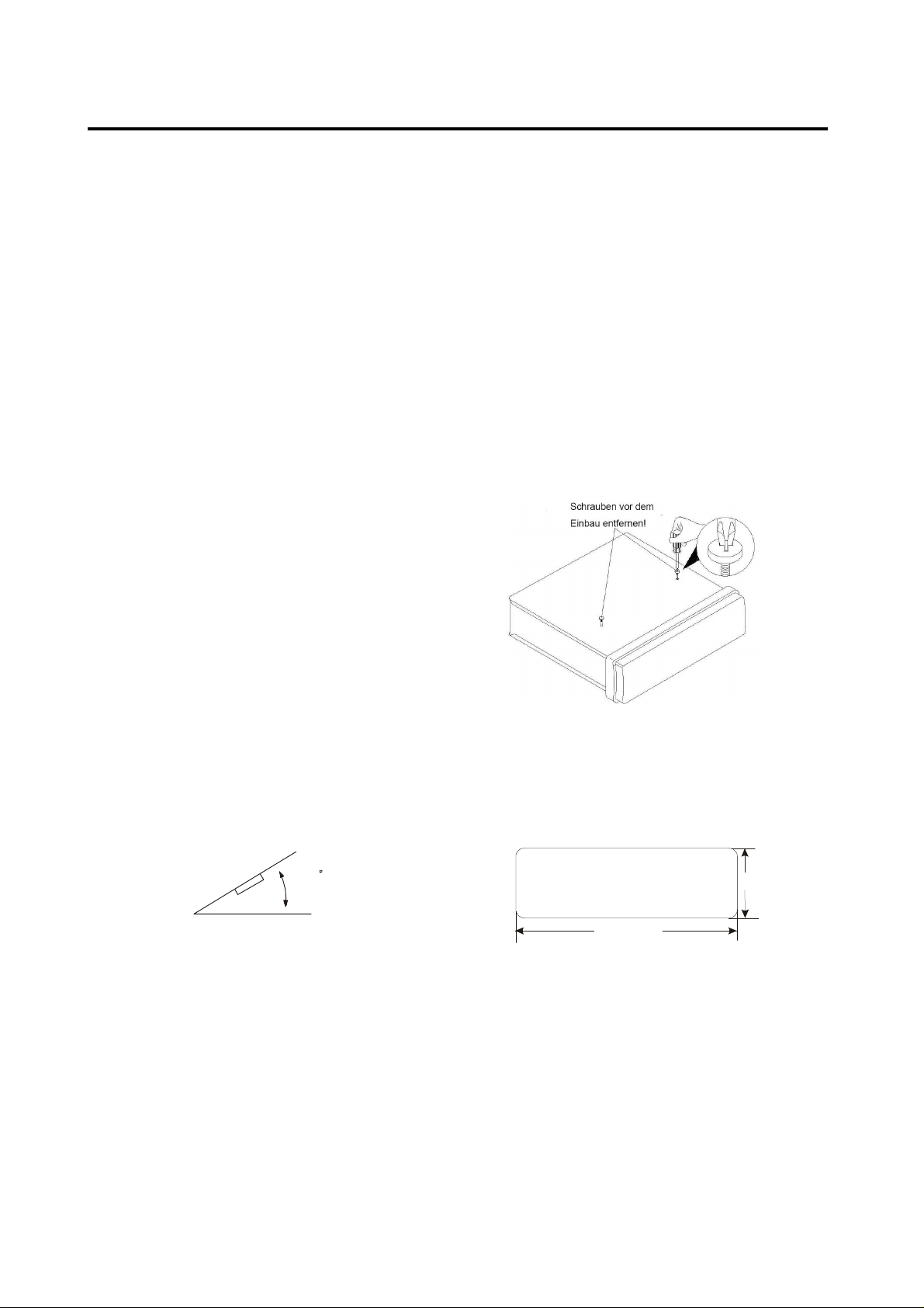
HERAUSNEHMEN DER SCHRAUBEN VOR
DEM EINBAU
Vor dem Einbau müssen folgende zwei
Schrauben entfernt werden.
DIN-VORDEREINBAU (Methode A)
Einbauöffnung
Dieses Gerät kann unter jedem
Armaturenbrett mit einer Einbauöffnung der
folgenden Größe eingebaut werden:
30
53mm
182mm
24
EINBAU
Einbau d
es Geräts
Vergewissern Sie sich, dass Sie die
Anschlüsse vorher getestet haben.
Benutzen Sie danach die folgenden
Schritte zum Einbau des Geräts.
1. Vergewissern Sie sich, dass die
Zündung ausgestellt ist und trennen Sie
das Kabel am Minuspol (-) der
Autobatterie ab.
2. Trennen Sie das Kabelgeschirr und die
Antenne ab.
3. Betätigen Sie den Entriegelungsknopf
an der Gerätevorderseite und nehmen
Sie die Bedientafel (siehe „Bedientafel
vom Gerät abnehmen”).
4. Heben Sie die Oberseite des
Außenrings hoch und ziehen den Ring
herunter.
5. Schieben Sie die beiden mitgelieferten
Montageschlüssel in den Einbaurahmen,
um diesen zu entfernen. Stecken Sie
die Schlüssel so weit es geht (mit den
Kerben nach oben zeigend) in die
entsprechenden Schlitzen an der
rechten und linken Seitenmitte.
Ziehen Sie dann den Einbaurahmen
vom Gerät herunter.
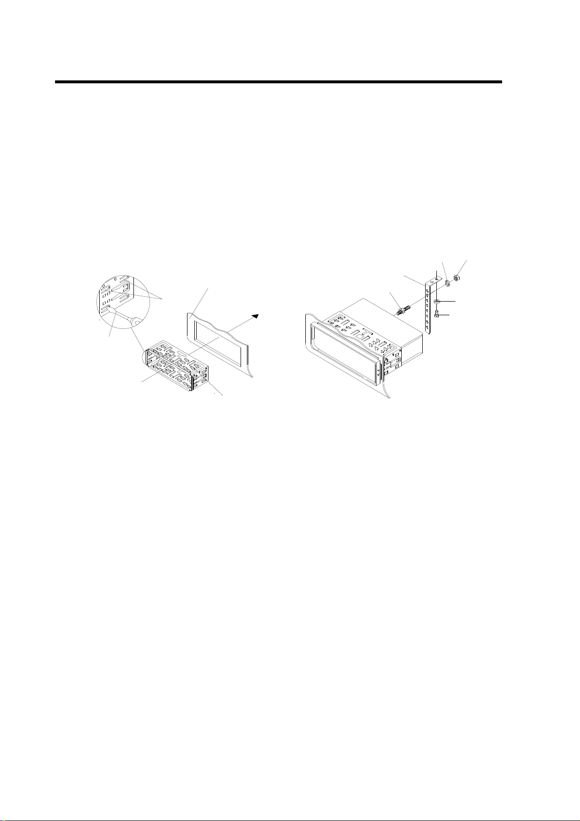
25
EINBAU
6. Bau
en Sie den Einbaurahmen in das
Armaturenbrett ein und drücken Sie die
Blechlaschen im Einbaurahmen mit
einem Schraubenzieher ein. Nicht alle
Blechlaschen sorgen für Kontakt.
Überprüfen Sie deshalb welche am
effektivsten sind. Biegen Sie die
entsprechenden Blechlaschen hinter
dem Armaturenbrett auf, um den
Einbaurahmen zu fixieren.
Tabs
Screwdriver
Sleeve
Dashboard
7. Schließen Sie das Kabelgeschirr und
die Antennen wieder an. Achten Sie
dabei darauf, dass keine Drähte oder
Kabel beschädigt werden.
8. Schieben Sie das Gerät in den
Einbaurahmen, bis es einrastet.
9. Zur zusätzlichen Befestigung an der
Rückseite des Geräts dient der
mitgelieferte Metallstreifen. Benutzen
Sie die mitgelieferten Metallteile (5 mm
Sechskantmutter und Federscheibe),
um das eine Ende des Metallstreifens
an der Schraube auf der Rückseite des
Geräts zu befestigen. Falls notwendig
können Sie den Metallstreifen biegen,
damit er in Ihrem Wagen befestigt
werden kann. Benutzen Sie dann die
mitgelieferten Metallteile (5 x 25 mm
Blechschraube und Unterlegscheibe),
um das andere Ende des
Metallstreifens unter dem Armaturenbrett
an einem festen Metallteil des Wagens
zu befestigen. Der Metallstreifen dient
außerdem dazu das Gerät sachgemäß
zu erden.
Hinweis: Befestigen Sie das kurze Teil
des Metallstreifens an der
Befestigungsschraube auf der Rückseite
des Geräts und das lange Teil am
Armaturenbrett.
Mounting Bolt
Spring Washer
Plain Washer
Tapping Screw
Hex Nut
Metal Strap
10. Schließen Sie das Stromkabel wieder
am Minuspol (-) der Autobatterie an.
Setzen Sie dann den Außenring zurück
auf das Gerät und befestigen Sie die
Bedientafel an der Vorderseite (siehe
Anleitung in Abschnitt „Anbringen der
Bedientafel“).
Entfernen des Geräts
1.Vergewissern Sie sich, dass die Zündung
ausgestellt ist und trennen Sie das Kabel
am Minuspol (-) der Autobatterie ab.
2.Entfernen Sie den Metallstreifen an der
Rückseite des Geräts (falls vorhanden).
3.
3.3.
3. Betätigen Sie den Entriegelungsknopf
an der Gerätevorderseite, um die
Bedientafel zu entfernen.
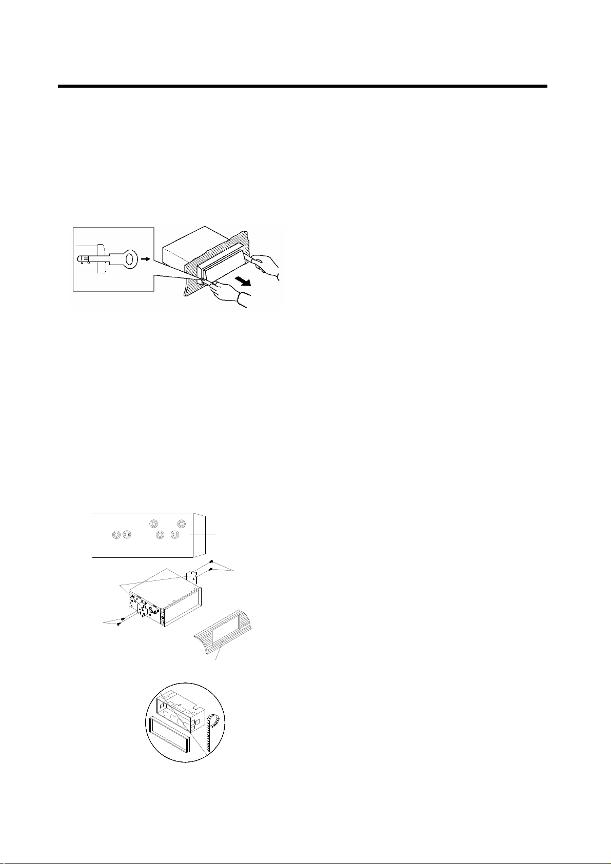
26
EINBAU
4.Heben
Sie die Oberseite des Außenrings
hoch und ziehen den Ring herunter.
5.Stecken Sie die mitgelieferten
Einbauschlüssel in die Schlitzen an der
rechten und linken Seitenmitte des
Geräts und ziehen Sie das Gerät aus
dem Armaturenbrett heraus.
DIN RÜCKSEITENEINBAU (Methode B)
Wenn Sie einen Nissan oder Toyota
besitzen, verwenden Sie die folgenden
Einbauanweisungen.
Benutzen Sie die mit T (für Toyota) oder N
(für Nissan) markierten Schraubbohrungen
an beiden Seiten des Geräts, um das Gerät
an den mitgelieferten Einbauschienen zu
befestigen.
Dashboard or Console
Screw
Factory Radio
Mounting Bracket
Side View showing
Screw Holes marked
T, N
Screw
Befestigung d
es Geräts an den
Einbauschienen.
Richten Sie die Schraublöcher in den
Einbauschienen auf die Schraublöcher am
Gerät aus und schrauben Sie die Schienen
mit den Schrauben (5 x 5 mm) fest.
Hinweis: Der Außenring, der
Einbaurahmen und der Metallstreifen
werden bei der Einbaumethode B nicht
benötigt.
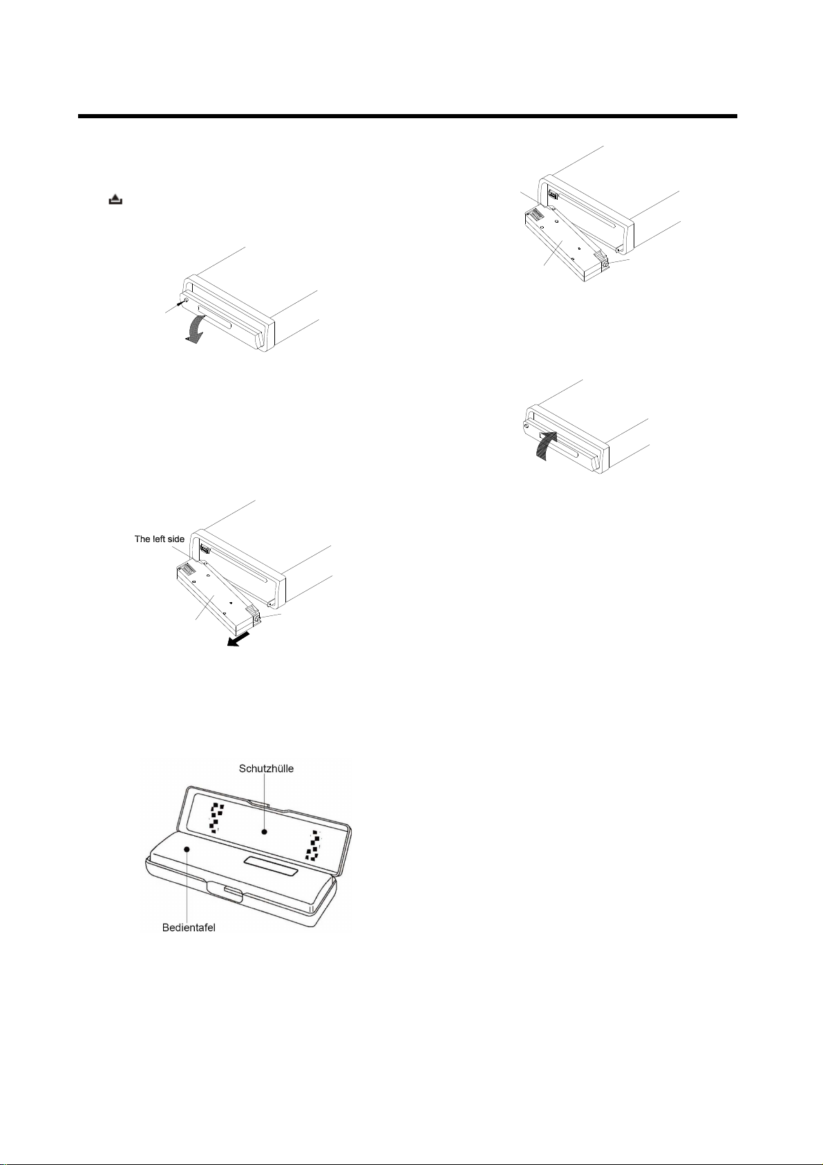
27
Entfernen
der Bedientafel
1. Betätigen Sie den Entriegelungsknopf
( ) und die Bedientafel klappt nach
unten.
OPEN
2. Um die Bedientafel zu entfernen, heben
Sie sie in einem leichten Winkel zur
Horizontalen an und ziehen Sie sie
zuerst auf der rechten und dann auf der
linken Seite heraus.
Front Panel
The right side
3. Um Beschädigungen zu vermeiden,
sollte die Bedientafel sofort nach dem
Entfernen in der mitgelieferten
Schutzhülle aufbewahrt werden.
Anbringen der Bedientafel
1. Um die Bedientafel wieder am Gerät zu
befesitigen, setzen Sie zunächst die linke
Seite in die richtige Position und dann die
rechte Seite.
The left side
Front Panel
The right side
2. Wenn beide Seite in der richtigen
Position sind, drücken Sie die
Bedientafel in das Gerät.
3. Beachten Sie, dass die Tasten nicht
benutzt werden können und die Anzeige
nicht richtig funktioniert, wenn die
Bedientafel bei der Befestigung nicht
richtig einrastet. Betätigen Sie in diesem
Fall den Entriegelungsknopf auf der
Bedientafel und befestigen Sie sie
erneut.
Handhabung der Bedientafel
1. Lassen Sie die Bedientafel nicht fallen.
2. Üben Sie keinen Druck auf die Anzeige
oder die Funktionstasten aus, wenn Sie
die Bedientafel abnehmen oder
befestigen.
3. Berühren Sie keine der Kontakte auf
der Bedientafel oder dem Hauptgerät.
Dies kann dazu führen, dass der
elektrische Kontakt verschlechtert wird.
4. Wenn Schmutz oder
Fremdgegenstände an den Kontakte
haften, können Sie mit einem sauberen,
trockenen Tuch entfernt werden.
BENUTZUNG DER ABNEHMBAREN BEDIENTAFEL

7. Versuchen Sie niemals die Bedientafel
Benzin, Verdünnungsmittel oder Insektizide).
28
5. Setzen Sie die Bedientafel niemals
hohen Temperaturen oder direktem
Sonnenlicht aus.
6. Halten Sie die Bedientafel fern von
leicht flüchtigen Substanzen ( z. B.
7.
auseinander zu bauen.
BENUTZUNG DER ABNEHMBAREN BEDIENTAFEL
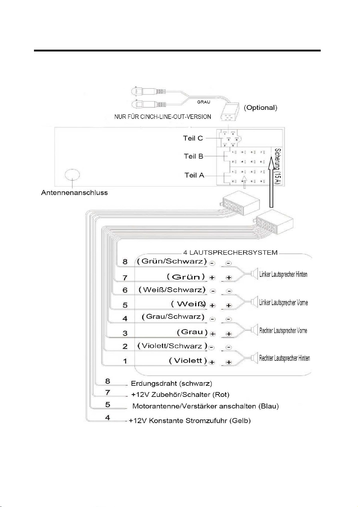
KABELANSCHLUSS
ISO-Anschluss
29
 Loading...