

Page 1
Page 2

Contents
Electrical Alignment Instructions
Page
- Technical data ................................................................................ 3
- Playback ......................................................................................... 4
1. Azimuth Adjustment
2. Tape Speed Adjustment
3. Output Level Adjustment
4. DNL Adjustment
- Recording ...................................................................................... 4
1. OSC Frequency Adjustment
2. Bias Trap Adjustment
3. Bias Current Adjustment
4. Dolby Nr. Bias Trap Adjustment
5. Input Sensitivity Adjustment
6. Level Meter Adjustment
7. Record Current Adjustment
8. Peak Indicator Level Adjustment
9. ALC Balance Adjustment
- Electrical Adjustment Procedure .......................................... 5+6
1. DC F.G. Servo Motor
2. RIP Head (Azimuth)
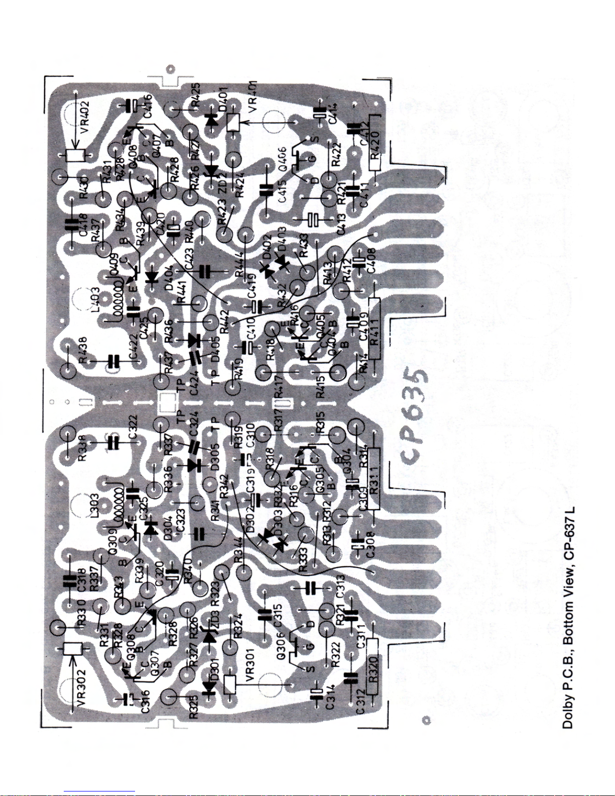
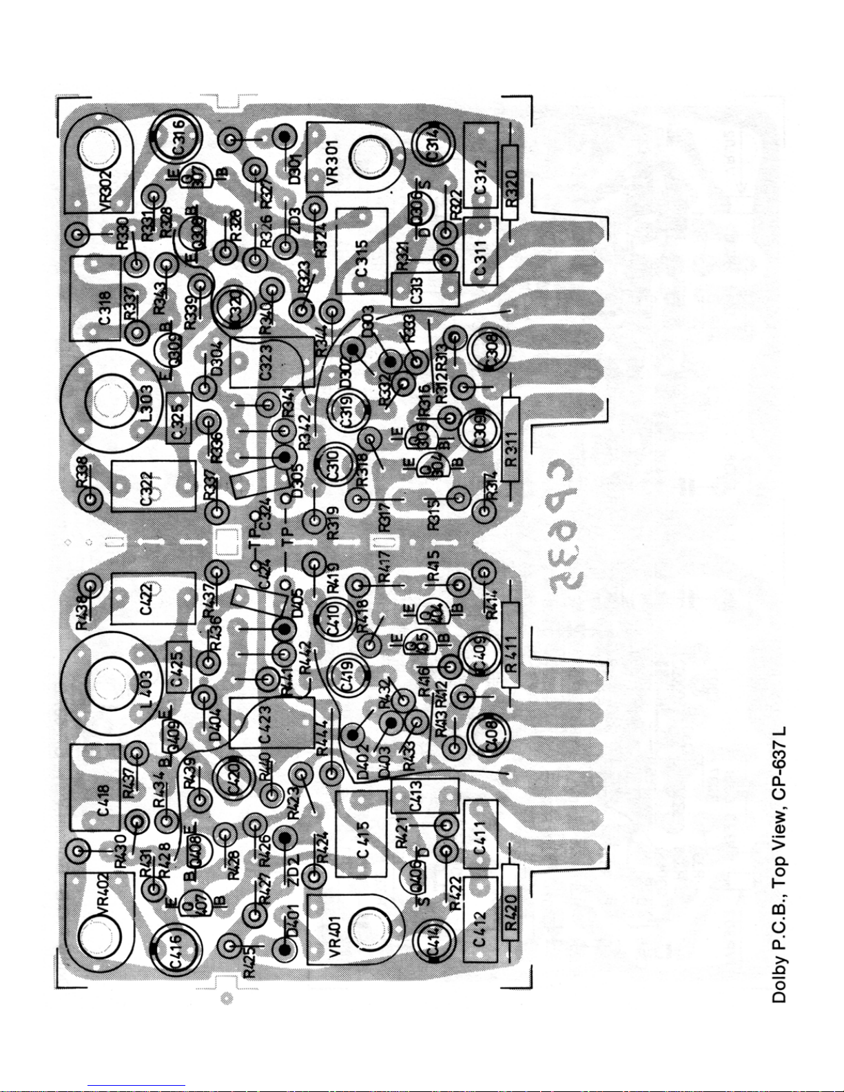
3. Dolby P.C.B.
4. DNL P.C.B.
5. Power P.C.B.
6. Pre Amp. P.C.B.
Mechanical Alignment Instructions
Page
- Tape Speed................................. 7
- Wow and Flutter ............................................................................... 7
- Mechanical Adjustment ........................................................ 8 + 9
1. Pinch Roller Pressure Measurement
2. Azimuth, Head Location Adjustment
3. Tape Speed Adjustment Location
Mechanical Parts List ........................................... 10-14
- Take-up Torque ............................................................................... 7
- Fast Forward and Rewind Torque ................................................... 7
- Pinch Roller Pressure ...................................................................... 7
- Tape Speed / Wow and Flutter ........................................................ 7
- Azimuth Head, Alignment ................................................................ 7
Electrical Parts List
............................................ 15-21
Drawings
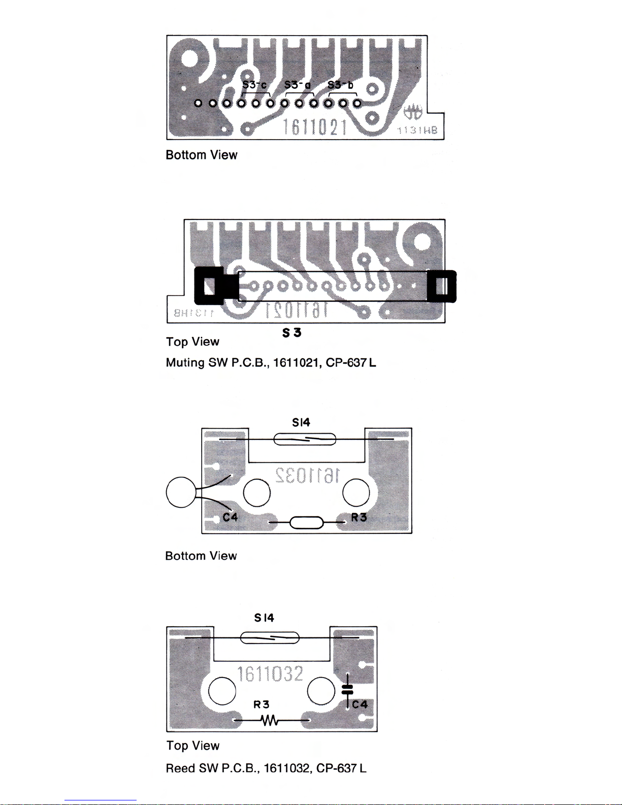
- Muting SW P.C.B. .................... ..................................................... 22
- Reed SW P.C.B. ...................... ..................................................... 22
- Mic Jack P.C.B. ........................ ..................................................... 23
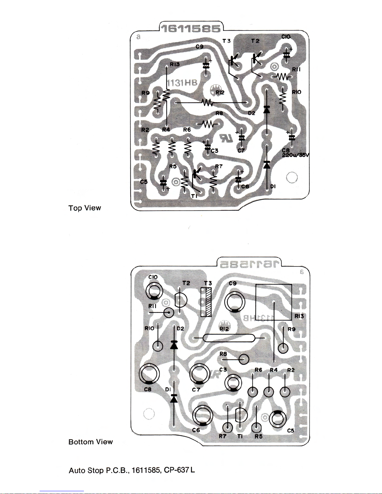
- Auto Stop P.C.B. ...................... ..................................................... 24
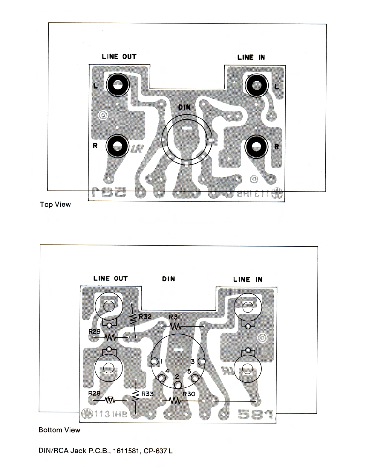
- DIN/RCA Jack P.C.B. ............... ..................................................... 25
- Power Supply P.C.B. (Bottom View) .............................. 26
- Power Supply P.C.B. (Top View) ................................... 27
- LED P.C.B. ............................... ..................................................... 28
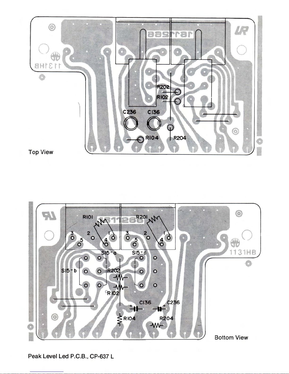
- Peak Level LED P.C.B. ............ ..................................................... 28
- PRE P.C.B. (Bottom View) .............................. 29
- PRE P.C.B. (Top View) ................................... 30
- Dolby P.C.B. (Bottom View) ............................. 31
- Dolby P.C.B. (Top View) ................................... 32
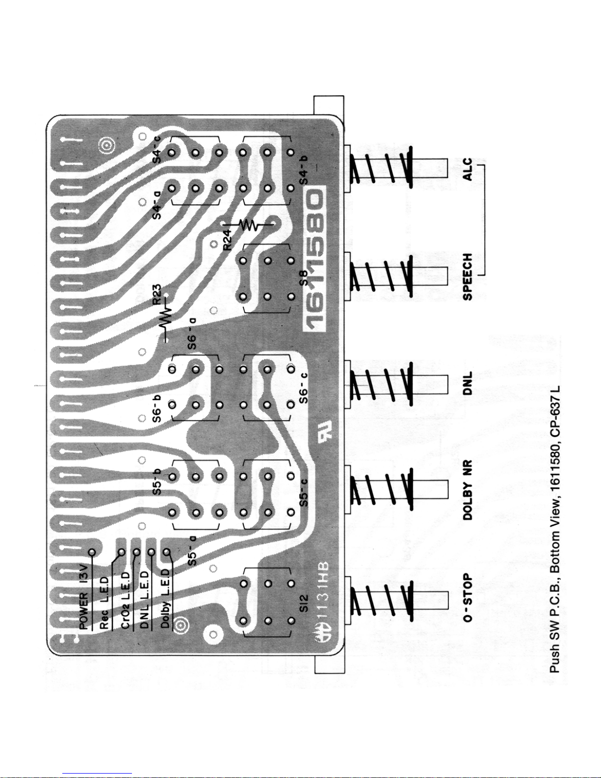
- Push SW P.C.B. (Bottom View) .............................. 33
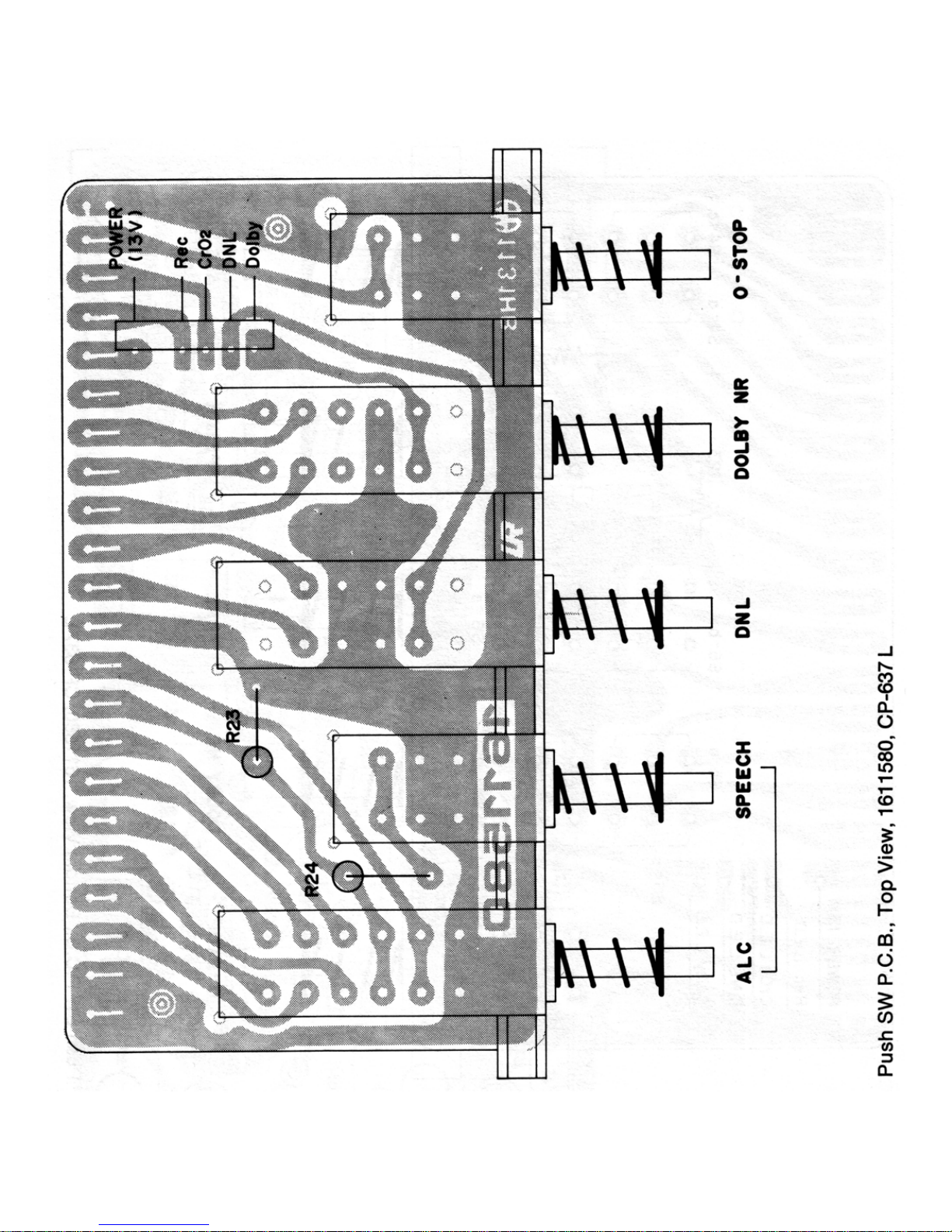
- Push SW P.C.B. (Top View) ................................... 34
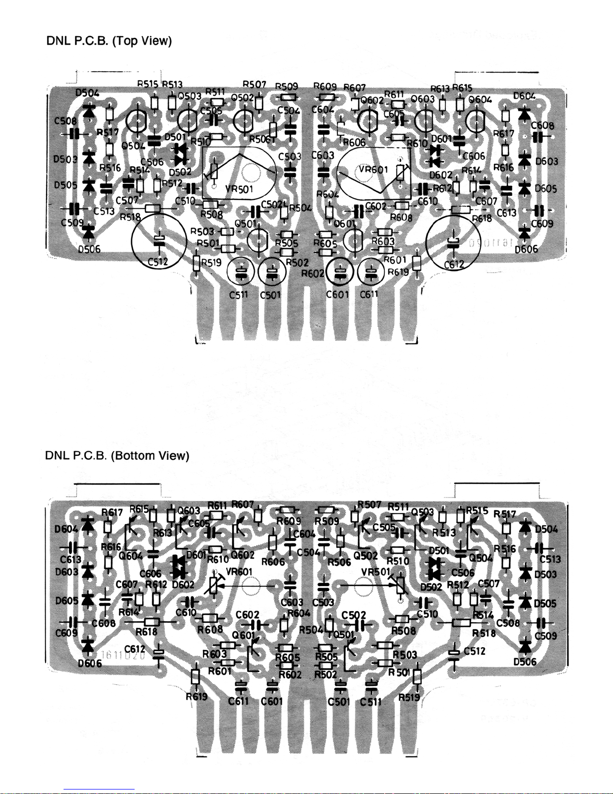
- DNL P.C.B. ............................... ..................................................... 35
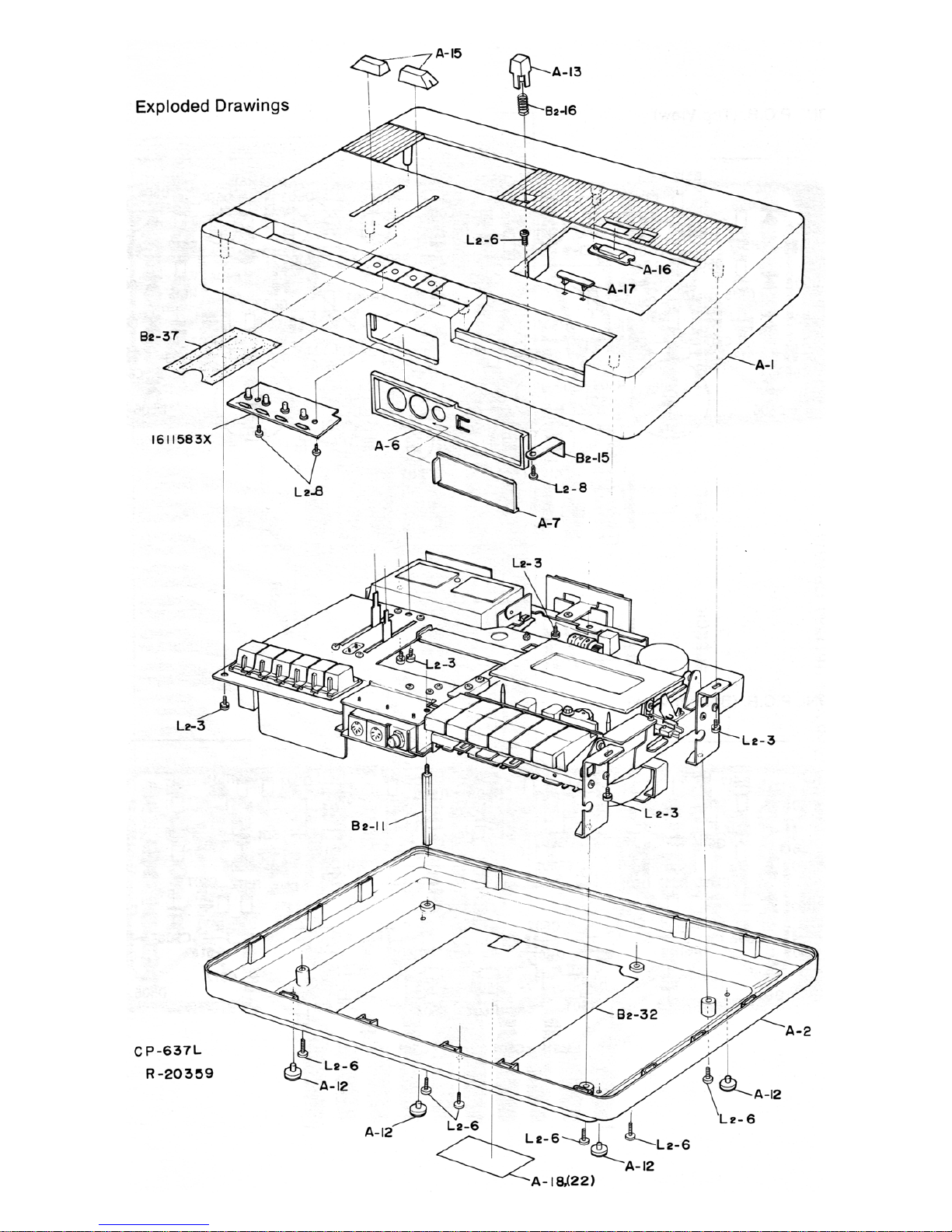
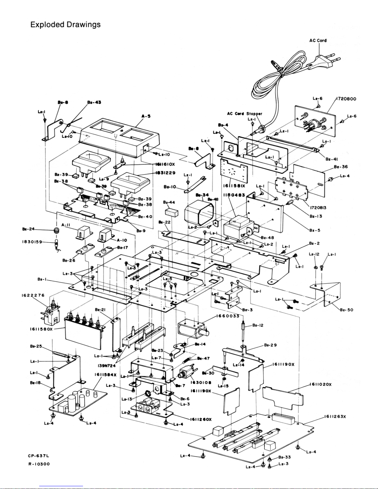
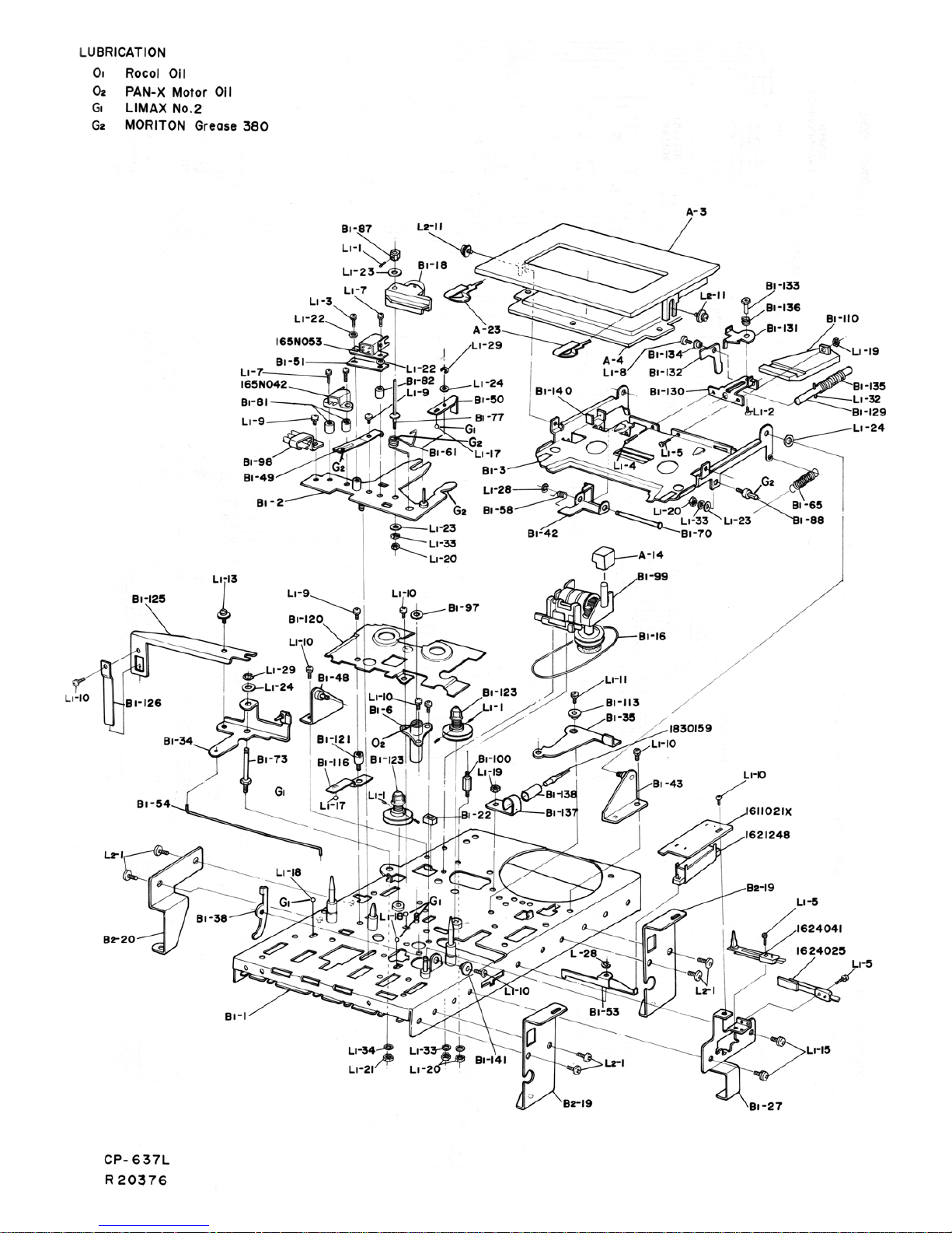
- Exploded drawings ................... ............................................... 36+37
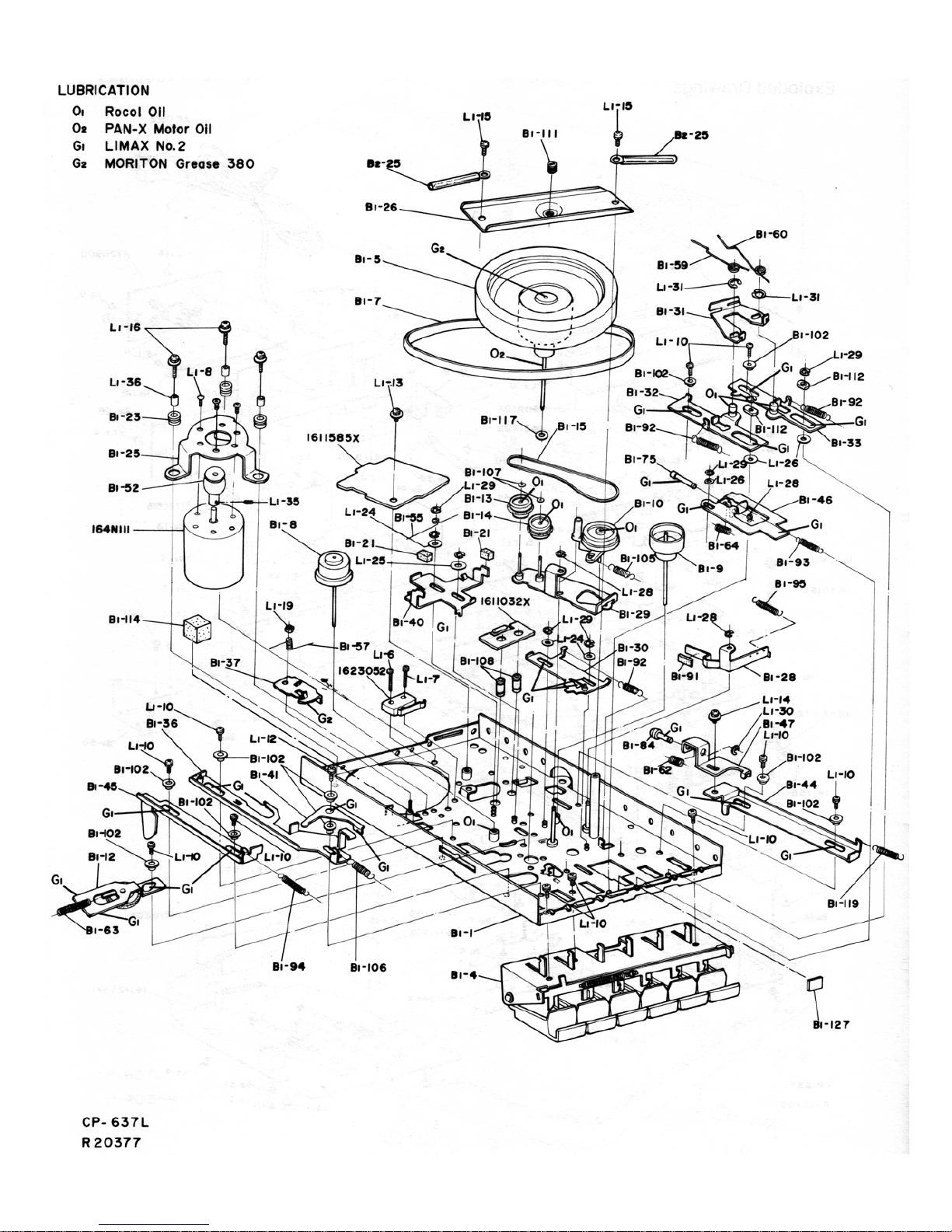
- Exploded and Lubrication drawings ......................................... 38+39
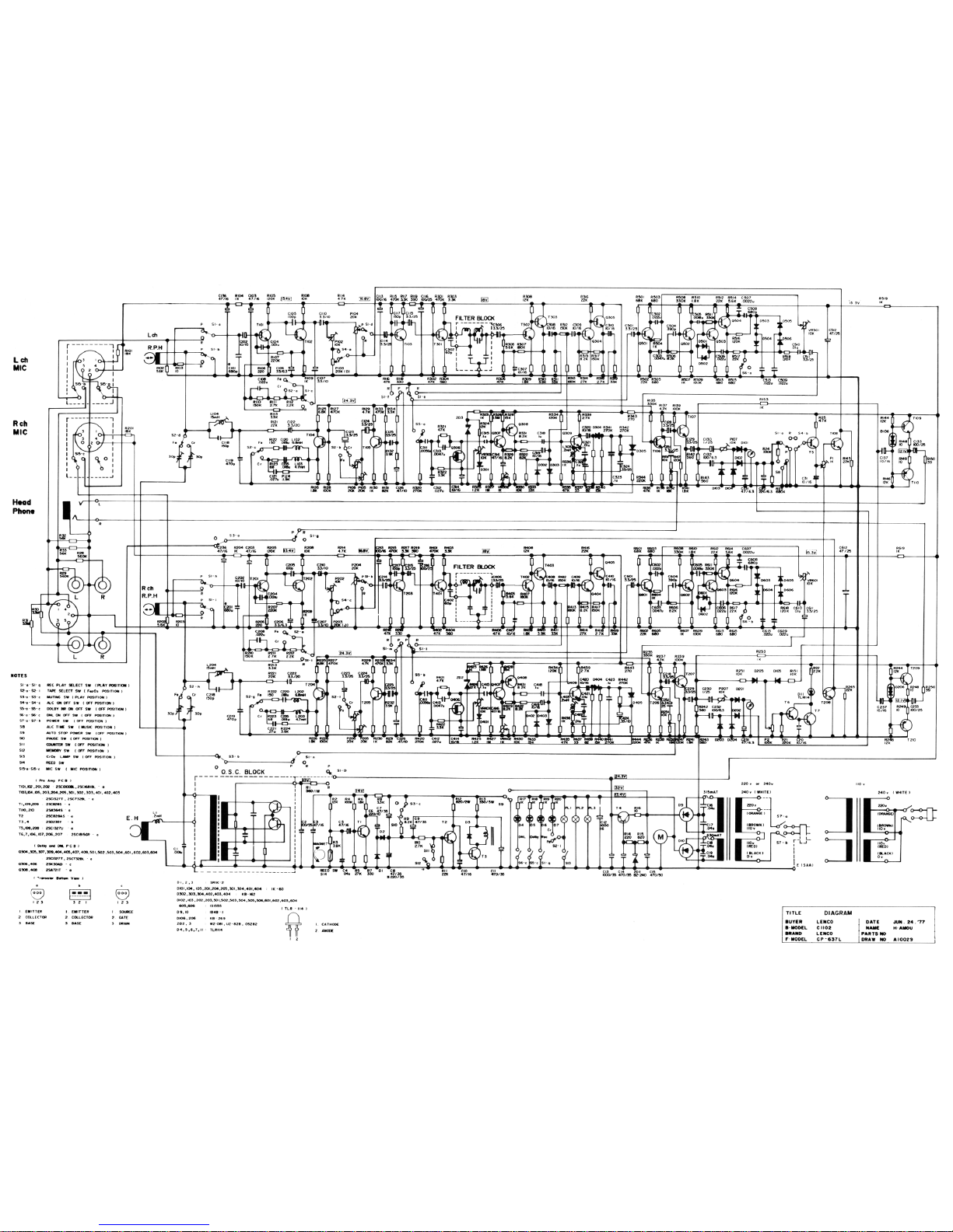
Wiring Diagram.......................... 40
Electrical Circuit Diagram ................................ ......... 40
Page 3

Technical data
Mains voltage:
220 V, can be resoldered for 110 V (Europe)
240 V (UK)
117 V (USA, ANP, Canada)
Mains frequency:
50 - 60 Hz
Power requirement:
0 W
Motors:
1 DC-motor with servo control
Cassettes:
Compact cassette:
Chrome dioxide BASF CrO
2
C 60 C 401 R
Standard TEAC MTT-502
Tape speed:
4.76 cm/s
Fast forward and rewind:
<75 s with C 60 cassette
Erase and bias frequency:
105 kHz
Level meter:
2 VU-meter
1 Peak Level Indicator
Dolby Level at
± 3 dB
Inputs: (for Dolby level)
1. Microphone input with DIN plug for low-impedance
microphones
Sensitivity: 330 µV imped. about 5.6 kOhms
Max. input voltage: 33 mV
Electret microphones: + 5 V max. 0.5 mA
2. Input DIN plug connections 1 + 4
Sensitivity: 0.33 mV impedance: 5.6 kOhms
(0.06 mVikOhm)
Max. input voltage: 33 mV
3. Line input PHONO plug
Sensitivity: 33 mV impedance: 560 kOhms
Max. input voltage: 3.3 V
4. Phono Input (DIN) DIN Plug connection 3+5
Sensitivity: 200 mV impedance: 3.3 mOhms
Outputs: (for Dolby level)
1. DIN plug, pin 3+5: 1000 mV impedance: 15 kOhms
2. LINE output (PHONO): 1000 mV impedance: 15 kOhms
3. Headphone output: 200 mV impedance: 8 kOhms
Harmonic distortion (333 Hz): (for 0 dB VU)
Standard cassette:
< 2.0 %
Ferri chrome cassette: < 2.0 %
Frequency response with: 20 dB VU
Standard cassette: 30-15000 Hz ± 3 dB
Ferri chrome cassette: 30-16000 Hz ± 3 dB
Wow + Flutter:
to WRMS < 0.06 % to DIN 45507 weighted
< ± 0.14 %
Drift: < ± 1.5 %
Signal/noise ratio: (DIN 45500)
(Reference 3 % third harmonic distortion)
Standard cassette: 53 dB 58 dB
Ferri chrome cassette: 54 dB 60 dB
without Dolby with Dolby
Cross talk: (1000 Hz)
with two track recording in opposite directions: > 60 dB with
stereo recording:
> 35 dB
Erase attenuation: (1000 Hz, full modulation Cr02 tape) >
62dB
Weight:
5.5 kg
Dimensions:
268 x 424 x 107 mm
Page 4

Alignment Instructions
Playback
1. Azimuth Adjustment
Connect a scope or VTVM to the right channel PRE-AMP OUTPUT
jack. Insert a test tape (TEAC MTT-114, 115) into the unit. Adjust the
Azimuth adjusting screw for maximum output into the right channel.
(See figure 1 R/P HEAD.)
2. Tape Speed Adjustment
Connect scope, VTVM and FREQUENCY COUNTER to the right
channel PRE-AMP OUTPUT jack. Insert a Test Tape (MTT-111 3
kHz) into the unit. Adjust the tape speed adjusting screw for a 3 kHz
value in the frequency counter. (See fig. 1 DC F.G. Servo Motor.)
3. Output Level Adjustment
Connect scope and VTVM to the TP-2 and Ground (L-ch and R-ch).
Insert a test tape MTT-150 (Dolby level calibration tape 200 nwb/m)
into the unit. Adjust the P 104 (left) and P 204 (right) for a 580 mV
reading.
4. DNL adjustment
Connect a scope to the PRE-AMP OUTPUT jack. Set the unit for a
PLAY function, then depress the PAUSE button, DNL switch, ON.
Adjust the VR 501 (L-ch), VR 601 (R-ch) so that the level of high
frequency noise is at a minimum on the scope. (See fig. 1, DNL
P.C.B.)
Recording
1. OSC Frequency Adjustment
Connect the scope and frequency counter to the terminals of the
erase head. Set the unit for recording. Adjust L 1 so that there is an
OSC frequency value of 105 kHz on the frequency counter. (See fig.
1 Power P.C.B.)
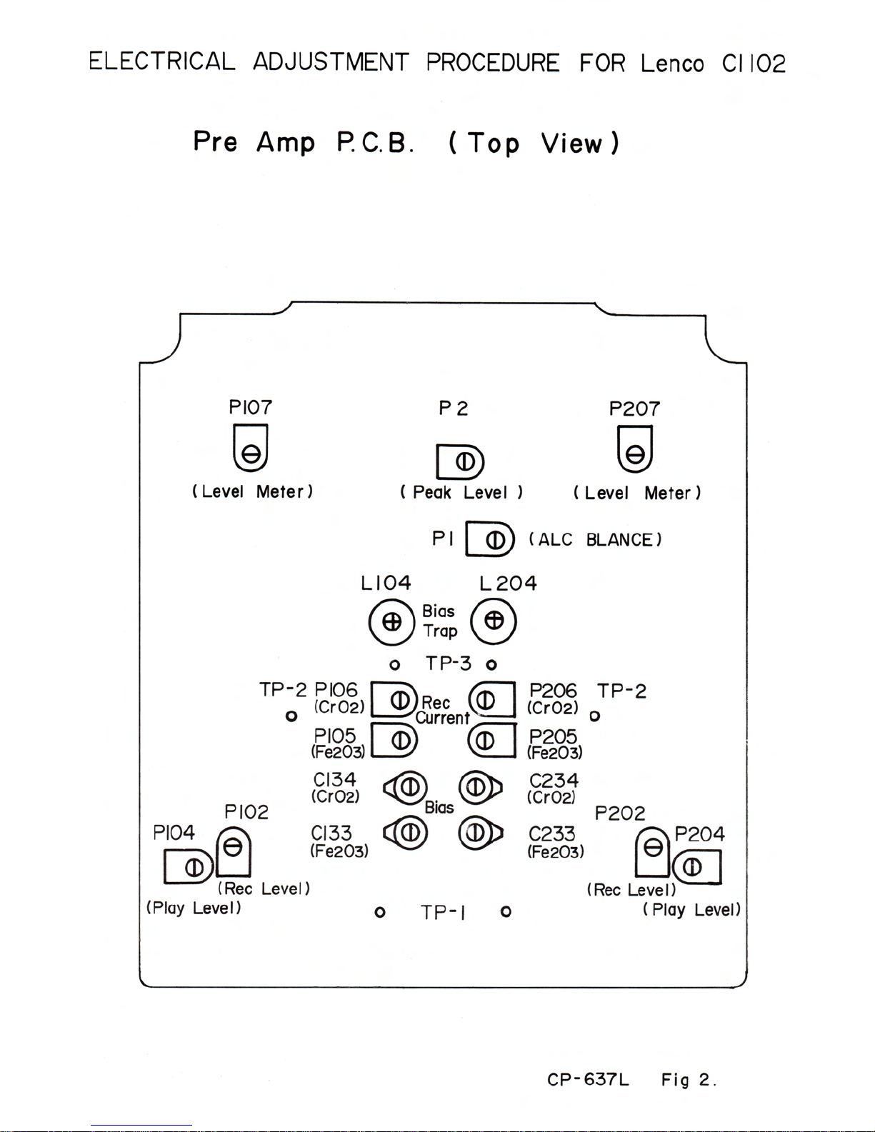
2. Bias Trap Adjustment
Connect the scope and VTVM to the TP-3 and Ground. (See fig. 2.)
Set the unit for recording. Adjust the L 104 (L-ch) and L 204 (R-ch) so
that the level on the VTVT is at a minimum. (See fig. 2.)
3. Bias Current Adjustment AF
Generator
333 Hz
1 kHz
0 dB - 1 V
Attenuator 95 dB Unit
Mic. Input L
R
V.T.V.M.
Scope
Connection should be made as above. Set the unit for recording. For
Fe 203, adjust C 133 (L-ch), C 233 (R-ch) to flat level at between 333
Hz and 10 kHz. For Cr02, adjust C 134 (L-ch), C 234 (R-ch) to flat
level at between 333 Hz and 12,5 kHz. (See figure 2.)
4. Dolby NR Bias Trap Adjustment
Connect the VTVM and scope to the test point pin on the Dolby
P.C.B. (See figure 1).
Set the unit for recording. Dolby NR switch "ON" position. Adjust L
303 (L-ch), L 403 (R-ch) for the minimum indication on the VTVM.
5. Input Sensitivity Adjustment AF
Generator
333 Hz
0 dB - 1 V
Attenuator
-70 dB Unit
DIN Input
L
R
TP-2
V.T.V.M.
Scope
Connection should be made as above. Set the unit for recording.
Record level controls (P 103, P 203) set at maximum. Adjust P 102
(L-ch), P 202 (R-ch) for 580 mV reading at TP 2 (L-ch, R-ch). (See
figure 2.)
6. Level Meter Adjustment
Connection should be made as for ADJUSTMENT 5. When
ADJUSTMENT 5 has been completed (580 mV rading at TP a),
adjust P 107 (L-ch), P 207 (R-ch) for +3 VU reading on level meters
(L-ch, R-ch). (See figure 2.)
7. Record Current Adjustment
Connection should be made as in ADJUSTMENT 5. Feed -70 dB
(333 Hz) into the DIN input. Set the record level controls (103/203) to
maximum.
Make a recording (use blank tape) then playback what has been
recorded and adjust P 105 (L-ch), P 205 (R-ch) for Fe 203 Tape, P
106 (L-ch), P 206 (R-ch) for Cr02 Tape so that the output at TP 2 has
a value of 580 mV. (See figure 2.)
8. Peak Indicator Level Adjustment
Set the unit for recording. Feed -68.5 dB (1 kHz) into the DIN input
Left and Right channels.
Adjust P 2 until the peak level indicator lights up. (See fig. 2).
AF Generator
1 kHz
0 dB = 1 V
Attenuator
-68.5 dB (1 kHz)
DIN Input
L
R
Unit
9. ALC Balance Adjustment
Disconnect R 1 (or cut the foil pattern) so that the Bias OSC is
stopped. Set the ALC switch to the "ON" position and keep the unit
set at recording. Feed -50 dB (1 kHz) signal into the DIN input Left
and Right channels. Adjust P 1 so that the value of the level meter on
Left and Right channel will be the same. (See figure 2 ALC
BALANCE).
AF Generator
1 kHz
0 dB = 1 V
Attenuator -50 dB
(1 kHz) Unit
DIN Input
L
R
Page 5

Page 6
Page 7

Mechanical Checks and Adjustments
Model C 1102
Note:
All the mechanical checks and alignments should be
done with the upper and bottom cabinet assembly (A-1 and A-
2) removed.
Take-up Torque
(Spec. 30-60 g/cm)
1.
Load the torque meter cassette.
2.
Set the unit in the play mode and read the value on the dial
scale. The meter should indicate a torque of 30 to 60 g/cm.
3.
If the torque range is out of the specified limit, clean the
driving surface of the take-up reel base shaft assembly (B
1-8) and tape-up pulley assembly (B 1-12) with pure
alcohol.
4.
If the above cleaning proves ineffective for a correct tor
que alignment, replace the take-up reel base shaft as
sembly.
5.
First, remove the reel table assembly (B 1-12), then pull
out the take-up reel base shaft assembly. After putting a
drop of oil on the reel shaft (B 1-17), insert the new part
and then fit the reel assembly onto it's shaft. Finally tighten
two set screws (L 1-1).
Fast-Forward and Rewind Torque
(Spec. 65-120 g/cm)
1. Load the torque meter cassette.
2. Set the unit at F.F. or REWIND mode and read the value on
the dial scale. The meter should indicate a torque of 65 to
120 g/cm.
3. If the value is outside the specified range, clean the driving
surface of the fast forward pulley A assembly (B 1-14), fast
forward pulley B (B 1-13) and C (B 1-14).
4. If the above cleaning operation is ineffective for a torque
alignment replace the fast forward pulley A assembly.
5. To replace, first remove the fast forward and rewind arm A
assembly (B 1-29).
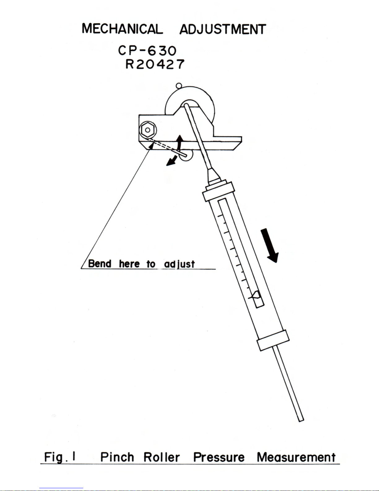
Pinch Roller Pressure
1. Place the unit in the play mode (but without a loaded tape).
2. Attach the spring scale to the edge of the pinch roller as
sembly (B 1-18) as shown (fig. 1).
3. Gently draw the pinch roller assembly away from the capstan
shaft (in a direction parallel to a line that inter cepts the
centre of the capstan shaft and the pinch roller) until the
capstan shaft and the pinch roller are completely separated.
4. Gradually lessen the pressure until the pinch roller just begins
to rotate. The scale should then read approximately 500-650
g/cm.
5. If the scale reading is outside the above range, replace the
pinch roller spring (B 1-61) or adjust the spring arm as shown.
6. After the replacement, install the pinch roller adjusting nut (B
1-87) with 1 mm vertical clearance. Check whether the pinch
roller is vertical to the capstan.
Tape Speed / WOW and Flutter
Note:
Before commencing the following alignments, make
sure that all parts in the tape path, particularly the capstan,
pinch roller and head, are cleaned with pure alcohol.
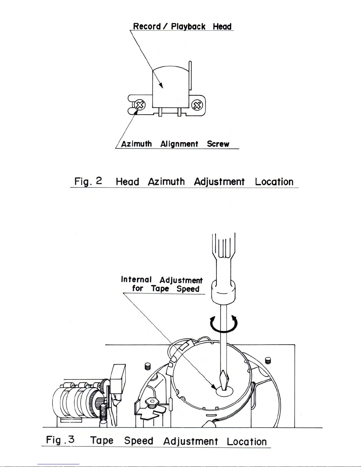
Head Azimuth Alignment
1. Connect the AC vacuum tube voltage meter to both chan
nels of the "Line-out".
2. Use a test tape (in which 10,000 Hz signal is recorded).
3. To achieve the maximum reading on the AC VTVM adjust the
azimuth alignment screw (fig. 2).
4. After the adjustment, fix the screw with lacquer.
Tape Speed
(Spec. 3000 Hz ± 45 Hz)
1. Connect the frequency counter to both channels of the lineout.
2. Set the EQ switch to normal position, then load and play a
TEAC MTT-111 test tape in which a 3000 Hz signal is
recorded.
3. Adjust the control located at the top of the meter for a reading
of 3000 Hz ± 5 Hz on the frequency counter (fig. 3). (This
tape speed alignment should be done after approx. 30
seconds operating time).
4. Then, verify the reading on the frequency counter as being
within the specified range 3000 Hz±45 Hz at the beginning,
middle and near the end of the tape.
Wow and Flutter
(Spec. DIN weighted: within ± 0.2% at record and playback)
Note: When using these methods, obtain the maximum wow and
flutter value, by repeated play, stop or pause mode of operation.
This operation ls necessary to make sure that the wow and
flutter value between record and playback will not create a false
reading.
1. Connect the oscillator to the line-in of the unit, and the wow
and flutter meter to either channel of the line-out.
2. Set line or record controls of the unit to obtain the optimum
input level.
3. Load a test tape (BASF C 60) and set the BASF/EQ
switches to the normal position.
4. Apply and record a 3000 Hz signal.
5. Record and play the recorded section.
6. Read the value on the wow and flutter meter. The wow and
flutter value should be within ± 0.2 %, DIN max.
7. If the measured value is out of specification, check the takeup torque and pinch roller pressure, and see that the capstan
or belt is not stretched or oily.
8. If the above checks prove ineffective, repair or replace the
pinch roller assembly (B 1-6), motor and any other defective
parts.
9. When the capstan assembly must be replaced, make sure it
is weil oiled. Re-adjust the end clearance by adjusting the
thrust-screw (B 1-111) until the clearance is between 0.15-0.3
mm.
Page 8
Page 9
Page 10

!
Parts List
CP-637 L (Lenco C 1102)
Mechanical Parts
Reference No.
Descrlption
Lenco Part No.
Quantity
Unlt Price
A-1
Cabinet Assembly, Top
21C7384X
1
Consists of following:
A-1 Cabinet, Top
21C7384
1
A-16 Window, Tapecounter
21W7472
1
B 2-37 Cover, Volume Control
24W7808
1
A-2
Cabinet Assembly, Bottom
21C7386X
1
Consists of following:
A-2 Cabinet, Bottom
21C7386
1
A-12 Rubber, Foot
21W7299
4
B 2-32 Paper, Shield
24W7641
1
A-3
Door Assembly, Cassette
21C7392X
1
Consists of following:
A-3 Door, Cassette
21C7392
1
A-4 Window, Cassette
2107088
1
A-23 Spring, Cassette Setting
23W9627
2
A-5
Box, VU Meter
21C7389
1
A-6
Cover, Microphone Jack
21C7390
1
A-7
Door, Microphone Jack
21C7391
1
A-10
Button, Push Switch
21N7597
5
A-11
Button, Power Switch
21N7598
1
A-13
Button, VU Meter Box
21N7602
1
A-14
Button, Tapecounter
21N7603
1
A-15
Knob, Volume Control
21N7604
2
A-17
Decoration Plate, Azimuth Hole
21W7473
1
A-18
Plate, Rating (220 V, 50 Hz)
23M7885
1
A-22
Plate, Rating (240 V, 50 Hz)
23M7890
1
B 1-1
Chassis Assembly
23S7191X
1
Consists of following:
B 1-1 Chassis, Mechanism
23S7191
1
B 1-17 Metal, Reel Shaft
22R7051
2
B 1-56 Stay, Auto Stop PC Board
25W8271
1
B 1-67 Stay, Flywheel Holder
25W7723
1
B 1-71 Shaft, Pause Lever B
25W7718
1
B 1-74 Stay, Basic
25W8172
2
B 1-83 Shaft, Head Chassis Guide
25W7713
2
B 1-85 Stay, Basic
25W7709
1
B 1-86 Shaft, Guide
25W7710
5
B 1-89 Shaft, Fast Forward Arm
25W7719
2
B 1-104 Shaft, Tape Changing Spring
25W7737
1
B 1-2
Plate Assembly, Head Base
23W8776X
1
Consists of following:
B 1-2 Chassis, Head
23W8776
1
B 1-76 Stay, Pinch Roller Arm
25W7712
1
B 1-79 Stay, Head Adjusting Spring
25W7720
1
B 1-83 Shaft, Head Chassis Guide
25W7713
1
B 1-3
Plate Assembly, Cassette Lifting
23W9940X
1
Consists of following:
B 1-3 Plate, Cassette Lifting
23W9940
1
A-19 Sheet A
24W7508
1
A-20 Sheet B
24W7509
1
B 1-140 Spacer
24W7443
1
B 1-4
Pushbutton Assembly
27N7060
1
B 1-5
Capstan Assembly
27W7060
1
Note:
Page 11

!
Reference No.
Descrlption
Lenco Part No.
Quantity
Unlt Prlce
B 1-6
Metal, Capstan
22H7050
1
B 1-7
Belt, Capstan
21V7068
1
B 1-8
Shaft Assembly, Take-up Reel Base
27W7061
1
B 1-9
Shaft Assembly, Supply Reel Base
27W7062
1
B 1-10
Pulley A Assembly, Fast Forward
27W7063X
1
Consists of following:
B 1-10 Pulley A, Fast Forward
27W7063
1
B 1-24 Arm, Fast Forward Pulley
21W7204
1
B 1-78 Shaft, Fast Forward Pulley
25W7683
1
B 1-101 Washer
24W7369
1
L 1-27 E-Ring Ø 1.5
EEU0015
1
B 1-12
Pulley Assembly, Take-up
21W7327X
1
Consist of following
B 1-12 Puliey, Take-up
21W7327
1
B 1-39 Arm, Take-up Pulley
23W8774
1
B 1-68 Shaft, Take-up Pulley
25W7681
1
L 1-27 E-Ring Ø 1.5
EEU0015
1 B 1-13
Pulley B, Fast Forward
27W7064
1
B 1-14
Pulley C, Fast Forward
27W7065
1
B 1-15
Belt, Fast Forward
21W7104
1
B 1-16
Belt, Counter
21V7040
1
B 1-18
Pinch Roller Assembly
21W7203X
1
Consist of following
B 1-18 Arm, Pinch Roller
21W7203
1
B 1-19 Pinch Rolier
27W7071
1
B 1-66 Shaft, Pinch-Roller
25W7741
1
B 1-21
Rubber, Brake
21W7201
2
B 1-22
Cushion, Door
21W7199
1
B 1-23
Cushion, Motor
21W7236
3
B 1-25
Holder, Motor
23X7262
1
B 1-26
Bracket A, Flywheel
23W8783
1
B 1-27
Bracket B, Flywheel
23W8765
1
B 1-28
Arm Assembly, Back Tension
23W8778X
1
Consists of following:
B 1-28 Arm, Back Tension
23W8778
1
B 1-91 Felt. Back Tension
24W7360
1
B 1-29
Arm A Assembly, Fast Forward and Rewind
23W8794X
1
Consists of following:
B 1-29 Arm A, Fast Forward and Rewind
23W8794
1
B 1-69 Shaft, Fast Forward Pulley B
25W7682
2
B 1-30
Arm B Assembly, Fast Forward and Rewind
23W8793X
1
Consists of following:
B 1-30 Arm B, Fast Forward and Rewind
23W8793
1
B 1-103 Shaft, Fast Forward and Rewind Arm B
25W7733
1
B 1-31
Arm C, Fast Forward and Rewind
23W8792
1
B 1-32
Arm Assembly, Fast Forward
23W8791X
1
Consists of following:
B 1-32 Arm, Fast Forward
23W8791
1
B 1-72 Shaft, Fast Forward and Rewind Arm C
25W7721
1
B 1-33
Arm Assembly, Rewind
23W8790X
1
Consists of following:
B 1-33 Arm, Rewind
23W8790
1
B 1-72 Shaft, Fast Forward and Rewind Arm C
25W7721
1
B 1-34
Arm A Assembly, Tape Changing
23W9954X
1
Consists of following
B 1-34 Arm A, Tape Changing
23W9954
1
B 1-96 Stop Pin
25W8169
1
Note:
Page 12

!
Reference No.
Description
Lenco Part No.
Quantity
Unit Price
B 1-35
Arm B, Tape Changing
23W8785
1
B 1-36
Lever A Assembly, Pause
23W8782X
1
Consists of following:
B 1-36 Lever A, Pause
23W8782
1
B 1-90 Shaft, Pause Lever A
25W7708
1 B 1-37
Lever B, Pause
23W8795
1
B 1-38
Lever C, Pause
23W8781
1
B 1-40
Arm, Brake
23W8773
1
B 1-41
Plate, Lock Release
23W9698
1
B 1-42
Plate, Record Prevention
23W8779
1
B 1-43
Angle B Assembly, Door
23W9749X
1
Consist of following
B 1-43 Angle B, Door
23W9749
1
B 1-80 Shaft B, Door
25W7946
1 B 1-44
Arm A, Record
23W8771
1
B 1-45
Lever B, Eject
23W9753
1
B 1-46
Arm, Head Chassis
23W8775
1
B 1-47
Arm B, Record
23W8770
1
B 1-48
Angle Assembly, Door
23W8777X
1
Consist of following
B 1-48 Angle, Door
23W8777
1
B 1-11 Shaft, Door
25W7704
1
B 1-49
Spring A, Head Chassis Holding
23W8789
1
B 1-50
Spring B, Head Chassis Holding
23W8788
1
B 1-51
Spring, R/P Head
23W8796
1
B 1-52
Pulley, Motor
25R7082
1
B 1-53
Spring, Slide Switch Changing
23W8772
1
B 1-54
Spoke, Switch Changing
26W7359
1
B 1-55
Spring, Brake Arm
26W7487
1
B 1-57
Spring, Pause Lever B
26W7249
1
B 1-58
Spring, Record Prevention Plate
26W7246
1
B 1-59
Spring, Fast Forward
26W7250
1
B 1-60
Spring, Rewind
26W7251
1
B 1-61
Spring, Pinch Roller
26W7244
1
B 1-62
Spring A, Push Shaft
26W7254
1
B 1-63
Spring, Take-up Pulley Arm
26W7245
1
B 1-64
Spring B, Push Shaft
26W7253
1
B 1-65
Spring, Door
26W7248
1
B 1-70
Shaft, Record Prevention Plate
25W7707
1
B 1-73
Shaft, Tape Changing Arm A
25W7715
1
B 1-75
Shaft, Head Chassis Pushing
25W7711
1
B 1-77
Shaft 8, Pinch Roller Arm
25W8004
1
B 1-81
Stay, Erase Head
25W7706
2
B 1-82
Stay, R/P Head
25W7705
1
B 1-84
Shaft, Record Arm B
25W7714
1
B 1-87
Nut B, Pinch Roller Adjusting
25W8005
1
B 1-88
Shaft, Eject Lever B
25W7717
1
B 1-92
Coil Spring A
26W7258
3
B 1-93
Coil Spring B
23W7259
1
B 1-94
Coil Spring C
26W7292
1
B 1-95
Spring, Back Tension Arm
23W7261
1
B 1-97
Washer, Oil Stopper
24W7370
1
B 1-98
Cramp, Shield Wire
23W8848
1
B 1-99
Counter Assembly
1670017X
1
Consists of following:
B 1-99 Counter
1670017
1
B 1-124 Washer
24W7505
1
Magnet Ring
1790100
1
B 1-100
Stay, Counter
25W7961
1
B 1-102
2 H pipe
25W7241
10
B 1-105
Coil Spring D
26W7265
1
B 1-106
Coil Spring E
26W7266
1
B 1-107
Washer B
24W7653
2
B 1-108
Cushion, Rubber
21W7210
2
B 1-110
Window, Tape Lighting
21 U7100
1
Note:
Page 13

!
Reference No.
Descrlption
Lenco Part No.
Quantity
Unit Price
B 1-111
Screw, Thrust
25W7132
1
B 1-112
Roller B, Guide
25W8000
2
B 1-113
Guide, Tape Changing Arm B
25W7595
1
B 1-114
Stay, Pause Lever B
21W7220
1
B 1-116
Spring C, Head Chassis Holding
23W8900
1
B 1-117
Washer, Thrust
24W7228
1
B 1-119
Spring, Record Arm A
26W7333
1
B 1-120
Cover, Chassis
23W9966
1
B 1-121
Stay, Chassis Cover
25W7781
1
B 1-123
Reel Table Assembly
27W7082
2
B 1-125
Arm C, Tape Changing
23W9425
1
B 1-126
Spring, Tape Changing
23W8800
1
B 1-127
Spacer, Head Chassis
23W9555
1
B 1-129
Bar, Eject
21W7253
1
B 1-130
Holder, Eject Bar
23W9086
1
B 1-131
Plate, Eject Bar Locking
23W9763
1
B 1-132
Plate, Lock Release
23W9764
1
B 1-133
Pipe, Locking Plate
25W7829
1
B 1-134
Pipe, Lock Release Plate
25W7830
1
B 1-135
Spring, Eject Bar
23W7315
1
B 1-136
Spring, Eject Bar Locking
23W7316
1
B 1-137
Holder, Lamp
23W9624
1
B 1-138
Cover, Lamp
21W7351
1
B 1-141
Pipe, Pause Lever C
25W8064
1
B 2-1
Chassis
23X7296
1
B 2-2
Joint A
23X7295
1
B 2-3
Joint B Assembly
23X7298X
1
Consists of following:
B 2-3 Joint B
23X7298
1
B 2-49 Spacer
25W0744
1
B 2-4
Bracket, Pin Jack
23X7301
1
B 2-5
Bracket, Transformer
23X7302
1
B 2-6
Holder, Microphone Jack
23X7290
1
B 2-7
Bracket, Microphone Jack
23X7291
1
B 2-8
Holder Assembly, VU Meter Box
23X7292X
2
Consists of following:
B 2-8 Holder, VU Meter Box
23X7292
2
B 2-42 Pin, VU Meter Box
25W7777
2
B 2-9
Plate Assembly, VU Meter
23X7293X
1
Consists of following:
B 2-9 Plate, VU Meter
23X7293
1
B 2-40 Cover, VU Meter Box
24T7258
1 B 2-10
Spring, VU Meter Box Locking
23X7294
1
B 2-11
Stay, Bottom Cabinet Holding
25W8281
1
B 2-12
Shaft, Record Arm C
25W8282
1
B 2-13
Stay, Terminal Board
25W8283
1
B 2-14
Lever, Auto Stop
23X7299
1
B 2-15
Arm, Meter Box Lifting
23X7300
1
B 2-16
Spring, Meter Box Lifting Button
26W7537
1
B 2-17
Holder, Push Switch Button
21W7311
5
B 2-18
Bracket, Power PCB
23W9560
1
B 2-19
Bracket, Mechanism Chassis
23W8734
2
B 2-20
Bracket B, Record/Playback PC Board
23W9413
1
B 2-21
Bracket C, Record/Playback PC Board
23W9419
1
B 2-22
Plate, PC Board
23W9566
1
B 2-23
Pipe, Auto Stop Lever
25W7518
1
B 2-24
Holder, Lamp
21W8502
2
B 2-25
Retainer, Wire
23W1046
3
B 2-26
Holder, Power Switch Button
21W7312
1
B 2-29
Lever C Assembly, Record
23W9423X
1
Consists of following:
B 2-29 Lever C, Record
23W9423
1
B 2-31 Shaft, Record Lever D
25W7959
1
Note:
Page 14

!
Reference No.
Description
Lenco Part No.
Quantity
Unit Price
B 2-30
Lever 0, Record
23W9564
1
B 2-33
Spring, Earth
26W7227
1
B 2-34
Shield, Transformer
23W9562
2
B 2-36
Plate, Insulation
24W7807
1
B 2-38
Cushion, Stopper
21W7013
4
B 2-39
Cushion, VU Meter
24W7805
4
B 2-41
Plate, Shelter
23X7303
1
B 2-43
Spring, Meter 80x Lifting
26W7242
1
B 2-44
Cushion, Meter 80x
24W7389
1
B 2-47
Spring, Auto Stop Lever
26W7439
1
B 2-48
Washer, Transformer
23W0255
2
B 2-50
Joint C
23X7426
1 L 1-1
Siotted Socket Setscrew M 2 X 3
SSI2003
5
L 1-2
Flat Countersunk Head Screw M 2 X 5
SDM1205
1
L 1-35
Siotted Socket Setscrew M 2.6 X 4
SSI2604
1
L 1-3
Pan Head Screw M 2 X 8
SPM1208
1
L 1-4
Pan Head SEMS Screw M 2 X 5
CPM1205
1
L 1-5
Pan Head SEMS Screw M 2 X 8
CPM1208
3
L 1-6
Pan Head SEMS Screw M 2 X 10
CPM1210
1
L 1-7
Pan Head SEMS Screw M 2 X 12
CPM1212
4
L 1-8
Pan Head Screw M 2.6 X 3
SPM1903
4
L 1-9
Pan Head SEMS Screw M 2.6 X 4
CPM1904
3
L 1-10
Pan Head SEMS Screw M 2.6 X 6
CPM1906
19
L 1-11
Pan Head SEMS Screw M 2.6 X 8
CPM1908
1
L 1-12
Pan Head SEMS Screw M 2.6 X 10
CPM1910
1
L 1-13
Pan Head W SEMS Screw M 2.6 X 6
FPM1906
2
L 1-14
Pan Head W SEMS Screw M 3 X 6
FPM3306
1
L 1-15
Pan Head SEMS Screw M 3 X 6
CPM3306
4
L 1-16
Pan Head W SEMS Screw M 3 X 12
FPM3312
3
Steel Ball Ø 2.5
80S0025
2
L 1-18
Steel Ball Ø 3
80S0030
3
L 1-19
Nut M 2
NHM0020
3
L 1-20
Nut M 2.6
NHM0026
4
L 1-21
Nut M 3
NHM0030
1
L 1-22
Flat Washer M 2 (0.4 t X Ø 5)
WP82054
2
L 1-23
Flat Washer M 2.6 (0.5 t X Ø 7.5)
WP89075
3
L 1-24
Flat Washer M 3.5 (0.5 t X Ø 7)
WP8C075
9
L 1-25
Flat Washer Ø 4 X Ø 10X 0.8 t
1
L 1-26
Flat Washer M 4 (0.5 t X Ø 10)
WP84103
3
L 1-28
E-Ring Ø 2
EEU0020
5 L 1-29
E-Ring Ø 2.5
EEU0025
10
L 1-30
E-Ring Ø 3
EEU0030
1
L 1-31
E-Ring Ø 4
EEU0040
2
L 1-32
Spring Pin Ø 1.6 X 12
PSK1612
1
L 1-33
Spring Washer M 2.6
WSM9056
4
L 1-34
Spring Washer M 3
WSM3067
1
L 1-36
Spacer Ø 3 X Ø 4 X 7
G003070
3 L 2-1
Tapping Screw (Tap-Tite C Type) M 3 X 6
36
L 2-2
Tapping Screw (Tape-Tite C Type) M 3 X 8
2
L 2-3
Pan Head SEMS Screw M 3 X 6
CPM3306
18
L 2-4
Pan Head W SEMS Screw M 3 X 6
FPM3306
7
L 2-5
Pan Head SEMS Screw M 3 X 5
CPM3305
3
L 2-6
8inding Head Screw M 3 X 8
S8K3308
9
L 2-7
Pan Head SEMS Screw M 2.6 X 6
CPM1906
1
L 2-8
Pan Head Tapping Screw M 2.6 X 6
3
L 2-9
Tapping Screw M 3 X 8
SLM3308
1
L 2-10
Flat Countersunk Head Screw M 2.6 X 6
SDK1906
2
L 2-11
Pan Head W SEMS Screw M 2.6 X 6
FPK1906
2
L 2-12
Nut M 3
NHM0030
1
L 2-13
Nut M 12
NHM0120
1
L 2-14
E-Ring Ø 3
1
L 2-15
E-Ring Ø 2.5
1
Note:
Page 15

!
Electrical Parts
Reference No.
Description
Lenco Part No.
Quantity
Unlt Price
Record/Playback Head
165N053
1
Erase Head
165N042
1
Level Meter
1831229
2
Power Transformer
118G483
1
AC Cord (COMMON-type)
1750277
1
AC Cord (BASEC-type)
1750280
1
AC Cord (SAA-type)
1750283
1
AC Cord Stopper (COMMON-type)
SR-4N-4
1
AC Cord Stopper (BASEC-type)
SR-5N-4
1
AC Cord Stopper (SAA-type)
SR-6W-1
1
DC FG-Servo Motor
164N111
1
S 1
Slide Switch (12-Circuit)
1621210, 1621259,
2
1621345
S 2
Slide Switch ( 9-Circuit)
1621318,1621237,
1
1621344
S 3
Slide Switch ( 4-Circuit)
1621248,1621341
1
S 4, 5, 6, 12
Push Switch (5-function- common)
1622298
1
Power Switch
1622276
1
Micro Switch
1623052
1
Leaf Switch
1624025
1
Leaf Switch
1624041
1
S 14
Reed Switch
1623133,1623136
1
S 15
Push Switch (2-Circuit)
1622195,1622174
2
P.C.B. Connector 10 P
172M459
1
P.C.B. Connector 6 P
172M584
2
Connector (5 P-3.5 mm)
172M606
1
Connector (3 P-3.5 mm)
172M604
13
Connector (5 P-2.5 mm) L-type
172M854
1
Connector Socket (5 P-3.5 mm)
172M870, 172M590
1
Connector Socket (3 P-3.5 mm)
172M588, 172M868 13
Connector Socket (5 P-2.5 mm)
172M862
1
P 103, 203
Slide Resistor 20 K (D)
139N724
2
DIN/RCA Jack Board
1720800
1
Terminal Board
1720813
1
DIN/RCA Jack P.C.B.
1611581
1
MIC Jack P.C.B.
1611266
1
Pre-Amplifier P.C.B.
1611263B
1
Dolby P.C.B.
1611190
1
DNL P.C.B.
1611020
1
Auto Stop P.C.B.
1611585
1
Push Switch P.C.B.
1611580
1
LED P.C.B. (4-function-common)
1611583
1
Peak Level LED P.C.B.
1611610
1
Power P.C.B.
1611584
1
Muting P.C.B.
1611021
1
Reed Switch P.C.B.
1611032
1
PL 1, 2, 3
Pilot Lamp
1830159
3
Solenoid Coil
1660033
1
Head Phone Jack (6.3 mm)
1630108
1
DIN Jack (P.C.B.-type)
1720401, 172C401
2
O.S.C. Block
1810074
1
Filter Block
1810098
2
Magnet Ring
1790100
1
Fuse (315 mAT)
1790095
1
Fuse (630 mAT)
1790098
1
L 102, 202
Semi-fixed Inductance 6.8 mH
1170100
2
L 103, 203
Semi-fixed Inductance 4.7 mH (J)
1170135
2
L 104, 204
Semi-fixed Inductance 15 mH
1170078
2
L 1, 303, 403
Semi-fixed Inductance 200 µH
1170069
3
Trimmer Capacitor
1280057
4
VR 302, 402
Semi-fixed Resistor (8 mm) 1 K
138N026
3
P102, 202
Semi-fixed Resistor (8 mm) 10 K
138N271
8
107, 207
VR 501, 601
301, 401
Page 16

!
Reference No.
Description
Lenco Part No.
Quantity
Unit Price
P 104, 204, 105
Semi-fixed Resistor (8 mm) 20 K
138N028
6
205,106,206
P2
Semi-fixed Resistor (8 mm) 100 K
138N004
1
MIC Jack P.C.B. Assembly
1611266X
MIC Jack P.C.B.
1611266
1
R 101, 201
Carbon Resistor
18 K
1337183
2
R102,202
Carbon Resistor
5.6 K
1337562
2
R 104, 204
Carbon Resistor
1
K
1337102
2
1622195
S 15
Push Switch (2-Circuit)
1622174
1
DIN/RCA Jack P.C.B. Assembly
1611581X
DIN/RCA Jack P.C.B.
1611581
1
R 28, 29
Carbon Resistor
560 K
W (J)
1346564
2
R 30, 31
Carbon Resistor
3.3 M
1321335
2
R 32, 33
Carbon Resistor
56
K
W (J)
1346563
2
DIN/RCA Jack Board
1720800
1
Peak Level P.C.B. Assembly
1611610X
Peak Level P.C.B.
1611610
1
011
Light Emitting Diode
TLR-114
1
Pre-Amplifier P.C.B. Assembly
1611263BX
Pre-Amplifier P.C.B.
1611263B
1
Filter Block
1810098
2
T 5
Transistor
2SC1327U
1
T 6,7
Transistor
2SC1815GR
2
T 10, 201
Transistor
2SC1000BL
4
102, 202
2SC1681BL
T 103, 203
Transistor
2SC1327T
6
104, 204
2SC732BL
105, 205
T 106, 206
Transistor
2SC1815GR
4
107, 207
T 108, 208
Transistor
2SC1327U
2
T 109, 209
Transistor
2SC828S
2
T 110, 210
Transistor
2SA564S
2
T 301, 401
Transistor
2SC1327T
6
302, 402
2SC732BL
303, 403
P 1
Semi-fixed Resistor
(8 mm)
1 K
138N026
1
P 2
Semi-fixed Resistor
(8 mm) 100 K
138N004
1
P 103, 203
Slide Resistor
20 K (0)
139N724
2
P 104, 204
Semi-fixed Resistor
(8 mm) 20 K
138N028
6
105, 205
106, 206
P 107, 207
Semi-fixed Resistor
(8mm)
10 K
138N271
2
L 102, 202
Semi-fixed Inductance
6.8 mH
1170100
2
L 103, 203
Semi-fixed Inductance
4.7 mH (J)
1170135
2
L 104, 204
Semi-fixed Inductance
15
mH
1170078
2
PL 1, 2, 3
Pilot Lamp
1830159
3
D 101, 201
Diode
1K-60
2
D 102, 202
Diode
1S1555
4
103, 203
D 104, 204
Diode
1K-60
4
105, 205
D 106, 206
Diode
KB-269
2
R 21
Carbon Resistor
220
K
1337224
2
R 22
Carbon Resistor
2.2 K
1337222
2
R 23
Carbon Resistor
680
K
1337684
2
R 24
Carbon Resistor
330
K
1337334
2
Note:
Page 17

!
Reference No.
Description
Lenco Part No.
Quantity
Unit Prlce
R 25
Carbon Resistor
4.7 K 1337472
2
R 103, 203
Carbon Resistor
10
1337100
2
R 105, 205
Carbon Resistor
120 K 1337124
2
R 106, 206
Carbon Resistor
220
1337221
2
R 107, 207
Carbon Resistor
220 K 1337224
2
R 108, 208
Carbon Resistor
10 K 1337103
2
R 109, 209
Carbon Resistor
1 K 1337102
2
R 110, 210
Carbon Resistor
150 K 1337154
2
R 111, 211
Carbon Resistor
2.7 K
1337272
2
R 112, 212
Carbon Resistor
2.2 K
1337222
2
R 113, 213
Carbon Resistor
3.3 K
1337332
2
R 114, 214
Carbon Resistor
4.7 K
1337472
2
R 115, 215
Carbon Resistor
470 K 1337474
2
R 116, 216
Carbon Resistor
47 K 1337473
2
R 117, 217
Carbon Resistor
3.3K
1337332
2
R 118, 218
Carbon Resistor
330
1337331
2
R 119, 219
Carbon Resistor
390
1337391
2
R 121, 221
Carbon Resistor
22 K 1337223
2
R 122, 222
Carbon Resistor
150
1337151
2
R 123, 223
Carbon Resistor
68
1337680
2
R 124, 224
Carbon Resistor
3.9 K 1337392
2
R 125, 225
Carbon Resistor
6.8 K
1337682
2
R 126, 226
Carbon Resistor
1.8 K
1337182
2
R 127, 227
Carbon Resistor
470 K 1337474
2
R 128, 228
Carbon Resistor
100 K 1337104
2
R 129, 229
Carbon Resistor
4.7 K
1337472
2
R 130, 230
Carbon Resistor
1 K 1337102
2
R 131, 231
Carbon Resistor
82 K 1337823
2
R 132, 232
Carbon Resistor
3.9 K
1337392
2
R 133, 233
Carbon Resistor
470 K 1337474
2
R 134, 234
Carbon Resistor
3.3 K
1337332
2
R 135, 235
Carbon Resistor
330 K 1337334
2
R 136, 236
Carbon Resistor
47 K 1337473
2
R 137, 237
Carbon Resistor
4.7 K
1337472
2
R 138, 238
Carbon Resistor
1 K 1337102
2
R 139, 239
Carbon Resistor
100 K 1337104
2
R 141, 241
Carbon Resistor
1.8 K
1337182
2
R 142, 242
Carbon Resistor
560
1337561
4
143, 243
R 144, 244
Carbon Resistor
12 K 1337123
2
R 145, 245
Carbon Resistor
22 K 1337223
2
R 146, 246
Carbon Resistor
12 K 1337123
2
R 147, 247
Carbon Resistor
120 K 1337124
2
R 148, 248
Carbon Resistor
10
1337100
2
R 149, 249
Carbon Resistor
10
1337100
2
R 150, 250
Carbon Resistor
39
1337390
2
R 151, 251
Carbon Resistor
10 K 1337102
2
R 152, 252
Carbon Resistor
18 K 1337183
2
R 153, 253
Carbon Resistor
1 K 1337102
2
R 301,401
Carbon Resistor
470
K 1337474
2
R 302, 402
Carbon Resistor
47
K 1337473
2
R 303, 403
Carbon Resistor
3.3 K
1337332
2
R 304, 404
Carbon Resistor
560
1337561
2
R 305, 405
Carbon Resistor
5.6 K
1337562
2
R 306, 406
Carbon Resistor
47 K 1337473
2
R 307, 407
Carbon Resistor
180 K 1337184
2
R 308, 408
Carbon Resistor
12 K 1337123
2
R 309, 409
Carbon Resistor
1.8 K
1337182
2
R 310, 410
Carbon Resistor
3.9 K
1337392
2
R 343, 443
Carbon Resistor
270
1337271
2
C 101, 201
Styrol Capacitor
680 p
1230681
2
C 102, 202
Tantal Electrolytic Capacitor
10 µ/10
1224106
2
C 103, 203
Electrolytic Capacitor
47 µ/16
1203476
2
C 104, 204
Myler Capacitor
0.001 µ (K)
1250102
2
C 105, 205
Ceramic Capacitor
100 p
1203101
2
C 106, 206
Electrolytic Capacitor
33 µ/6.3
1201336
2
Note:
Page 18

!
Reference No.
Description
Lenco Part No.
Quantity
Unit Price
C 107, 207
Tantal Electrolytic Capacitor
3.3 µ/10
1224335
2
C 108, 208
Myler Capacitor
0.022 µ (J)
1254223
2
C 110, 210
Tantal Electrolytic Capacitor
3.3 µ/10
1224335
2
C 113, 213
Electrolytic Capacitor
100 µ/16
1203107
2
C 114, 214
Tantal Electrolytic Capacitor
3.3 µ/10
1224335
2
C 115, 215
Electrolytic Capacitor
3.3 µ/25
1204335
2
C 116, 216
Electrolytic Capacitor
100 µ/25
1204107
2
C 117, 217
Ceramic Capacitor
150 p
12D3151
4
118, 218
C 119, 219
Ceramic Capacitor
470 p
12D3471
2
C 120, 220
Myler Capacitor
0.018 µ (J)
1254183
2
C 121, 221
Myler Capacitor
0.027 µ (J)
1254273
2
C 122, 222
Tantal Electrolytic Capacitor
3.3 µ/25
1225335
2
C 123, 223
Electrolytic Capacitor
3.3 µ/25
1204335
2
C 124, 224
Electrolytic Capacitor
3.3 µ/25
1204335
4
125, 225
C 126, 226
Aluminium Solid Element Capacitor 0.47 µ/10
1211474
2
C 128, 228
Electrolytic Capacitor
3.3 µ/25
1204335
4
129, 229
C 130, 230
Electrolytic Capacitor
1 µ/25
1204105
2
C 131, 231
Electrolytic Capacitor
47 µ/6.3
1201476
2
C 132, 232
Electrolytic Capacitor
100 µ/6.3
1201107
2
C 133, 233
Electrolytic Capacitor
100 µ/25
1204107
2
C 137, 237
Electrolytic Capacitor
10 µ/16
1203106
2
C 151, 251
Electrolytic Capacitor
3.3 µ/25
1204335
2
C 302, 402
Ceramic Capacitor
60 p
12D3600
2
C 306, 406
Electrolytic Capacitor
3.3 µ/25
1204335
2
C 307, 407
Electrolytic Capacitor
10 µ/16
1203106
2
C 20
Electrolytic Capacitor
10 µ/16
1203106
2
C 30
Electrolytic Capacitor
220 µ/6.3
1201227
2
C 31
Electrolytic Capacitor
10 µ/16
1203106
2
Dolby P.C.B. Assembly
1611190X
Dolby P.C.B.
1611190
1
Q 304, 404
Transistor
2SC732BL
2
2SC1327T
Q 305, 405
Transistor
2SC732BL
2
2SC1327T
Q 306, 406
Transistor
2SK30AD
2
Q 307, 407
Transistor
2SC732BL
2
2SC1327T
Q 308, 408
Transistor
2SA721T
2
Q 309, 409
Transistor
2SC732BL
2
2SC1327T
D 301, 401
Diode
1 K-60
2
D 302, 402
Diode
KB-162
8
D 303, 403
D 304, 404
D 305, 405
VR 301, 401
Semi-fixed Resistor
(8 mm) 10 K
138N271
2
VR 302, 402
Semi-fixed Resistor
(8 mm) 1 K
138N026
2
ZD 2,3
Zener Diode
WZ-018
2
UZ-82B
2
05Z82
2
L 303, 403
Semi-fixed Inductance
0.2 mH
117D069
2
R 311, 411
Carbon Resistor
33 K 1321333
2
R 312, 412
Carbon Resistor (Precision)
150
K/ W
1330052
2
R 313, 413
Carbon Resistor (Precision)
180
K/ W
1330053
2
R 314, 414
Carbon Resistor
27 K 1337273
2
R 315, 415
Carbon Resistor
8.2 K
1337822
2
R 316, 416
Carbon Resistor
22 K 1337223
2
R 317, 417
Carbon Resistor (Precision)
150
K/ W
1330052
2
R 318, 418
Carbon Resistor
2.7 K
1337272
2
R 319, 419
Carbon Resistor
33 K 1337333
2
R 320, 420
Carbon Resistor
270 K 1321274
2
Note:
Page 19

!
Reference No.
Descrlptlon
Lenco Part No.
Quantlty
Unlt Prlce
R 321, 421
Carbon Resistor
47 K 1337473
2
R 322, 422
Carbon Resistor (Precision)
3.3 K / W
1330051
2
R 323, 423
Carbon Resistor
1 K 1337102
2
R 324, 424
Carbon Resistor
12 K 1337123
2
R 325, 425
Carbon Resistor
1.2 K
1337122
2
R 326, 426
Carbon Resistor
1.5 M
1337155
2
R 327, 427
Carbon Resistor
1 M 1337105
2
R 328, 428
Carbon Resistor
15 K 1337153
2
R 329, 429
Carbon Resistor
8.2 K
1337822
2
R 330, 430
Carbon Resistor
10 K 1337103
2
R 331, 431
Carbon Resistor
8.2 K
1337822
4
332, 432
R 333, 433
Carbon Resistor
33
K
1337333
2
R 334, 434
Carbon Resistor
120 K 1337124
2
R 335, 435
Carbon Resistor
47 K 1337473
2
R 336, 436
Carbon Resistor
1 K 1337102
2
R 337, 437
Carbon Resistor
33
1337330
2
R 338, 438
Carbon Resistor
82
1337820
2
R 339, 439
Carbon Resistor
2.7 K
1337272
2
R 340, 440
Carbon Resistor
15 K 1337153
2
R 341, 441
Carbon Resistor
270 K 1337274
2
R 342, 442
Carbon Resistor
270 K 1337274
2
R 344, 444
Carbon Resistor
220 K 1337224
2
C 308, 408
Electrolytic Capacitor
10 µ/16
1203106
6
309, 409
310, 410
C 311, 411
Precision Film Capacitor
0.0056 µ
1220124
2
C 312, 412
Precision Film Capacitor
0.027 µ
1220123
2
C 313, 413
Precision Film Capacitor
0.0047 µ
1220125
2
C 314, 414
Electrolytic Capacitor
10 µ/16
1203106
2
C 315, 415
Myler Capacitor
0.1 µ (K)
1250104
2
C 316, 416
Electrolytic Capacitor
47 µ/16
1203476
2
C 318, 418
Myler Capacitor
0.1 µ (K)
1250104
2
C 319, 419
Electrolytic Capacitor
10 µ/16
1203106
4
320, 420
C 321, 421
Myler Capacitor
0.01 µ (K)
1250103
2
C 322, 422
Myler Capacitor
0.1 µ
(J) 1254104
2
C 323, 423
Myler Capacitor
0.1 µ (K)
1250104
2
C 324, 424
Alminium Solid Element Capacitor
0.33 µ/10
1211334
2
Auto Stop P.C.B. Assembly
1611585X
Auto Stop P.C.B.
1611585
1
T 1
Transistor
2SC828S
1
T 2
Transistor
2SC828AS
1
T 3
Transistor
2SD235Y
1
D 1, 2
Diode
SR1K-2
2
R 2
Carbon Resistor
12 K 1337123
1
R 4
Carbon Resistor
100 K 1337104
1
R 5
Carbon Resistor
27 K 1337273
1
R 6
Carbon Resistor
1.8 K
1337182
1
R 7
Carbon Resistor
330
1337331
1
R 8
Carbon Resistor
3.3 K
1337332
1
R 9
Carbon Resistor
8.2 K
1337822
1
R 10
Carbon Resistor
2.7 K
1337272
1
R 11
Carbon Resistor
22 K 1337223
1
R 12
Metal Oxide Resistor
820/2 W
1340821
1
R 13
Cement Resistor
330/5 W
1330055
1
1330056
C 3, 5
Electrolytic Capacitor
47 µ/16
1203476
2
C 6
Electrolytic Capacitor
220 µ/10
1202227
1
C 7
Electrolytic Capacitor
47 µ/35
1200476
1
C 8
Electrolytic Capacitor
220 µ/35
1200227
1
C 9
Electrolytic Capacitor
47 µ/35
1200476
1
C 10
Electrolytic Capacitor
47 µ/16
1203476
1
C 11
Electrolytic Capacitor
470 µ/35
1200477
1
Note:
Page 20

!
Reference No.
Descrlption
Lenco Part No.
Quantity
Unlt Prlce
DNL P.C.B. Assembly
1611020X
DNL P.C.B.
1611020
1
Q 501, 601
Transistor
28C1327T
8
502, 602
28C732BL
503, 603
504, 604
D 501, 601
Diode
181555
12
502, 602
503, 603
504, 604
505, 605
506, 606
VR 501, 601
Semi-fixed Resistor
10 K 138N271
2
R 501, 601
Carbon Resistor
68 K 1337683
2
R 502, 602
Carbon Resistor
22 K 1337223
2
R 503, 603
Carbon Resistor
680
1337681
2
R 504, 604
Carbon Resistor
1 K 1337102
2 R 505, 605
Carbon Resistor
680 1337681
2
R 506, 606
Carbon Resistor
8.2 K
1337822
2
R 507, 607
Carbon Resistor
1 K 1337102
2
R 508, 608
Carbon Resistor
330 K 1337334
2
R 509, 609
Carbon Resistor
100 K 1337104
2
R 510, 610
Carbon Resistor
1.8 K
1337182
2
R 511, 611
Carbon Resistor
330 K 1337334
2
R 512, 612
Carbon Resistor
22 K 1337223
2
R 513, 613
Carbon Resistor
680
1337681
2
R 514, 614
Carbon Resistor
5.6K
1337562
2
R 515, 615
Carbon Resistor
680
1337681
2
R 516, 616
Carbon Resistor
120 K 1337124
2
Note:
Page 21

!
Reference No.
Description
Lenco Part No.
Quantity
Unit Price
R 517, 617
Carbon Resistor
22 K 1337223
2
R 518, 618
Carbon Resistor
120 K 1337124
2
R 519, 619
Carbon Resistor
1 K 1337102
2
C 501, 601
Electrolytic Capacitor
3.3 µ/25
1204335
2
C 502, 602
Myler Capacitor
0.022 µ (K)
1250223
2
C 503, 603
Myler Capacitor
0.0047 µ (K)
1250472
2
C 504, 604
Styrol Capacitor
390 p (J)
1230390
2
C 505, 605
Myler Capacitor
0.0018 µ (K)
1250182
2
C 506, 606
Myler Capacitor
0.022 µ (K)
1250223
2
C 507, 607
Myler Capacitor
0.0022 µ (K)
1250222
2
C 508, 608
Styrol Capacitor
680 p
1230681
2
C 509, 609
Myler Capacitor
0.022 µ (K)
1250223
2
C 510, 610
Myler Capacitor
0.01 µ (K)
1250103
2
C 511, 611
Electrolytic Capacitor
3.3 µ/25
1204335
2
C 512, 612
Electrolytic Capacitor
47 µ/25
1204476
2
C 513, 613
Myler Capacitor
0.022 µ (K)
1250223
2
Power P.C.B. Assembly
1611584X
Power P.C.B.
1611584
1
OSC Block
1810074
1
T 4
Transistor
2SD235Y
1
D 9, 10
Diode
1 B4B-1
2
ZD 1
Zener Diode
BZ-240
1
R 1
Metal Oxide Resistor
560/1 W
1334561
1
R 14
Carbon Resistor
220
1337221
1
R 15
Carbon Resistor
820
1337821
1
R 16
Metal Oxide Resistor
10/1 W
1344100
1
C 1
Styrol Capacitor
1000 p (J)
1231102
1
C 2
Electrolytic Capacitor
100 µ/25
1204107
1
C 12
Electrolytic Capacitor
1000 µ/16
1203108
1
C 13
Electrolytic Capacitor
1000 µ/35
1200108
1
C 14
Electrolytic Capacitor
470 µ/35
1200477
1
C 15
Electrolytic Capacitor
470 µ/50
1221477
1
C 16, 17, 18, 19
Ceramic Capacitor
0.04 µ 1203402
4
Reed Switch P.C.B. Assembly
1611032X
Reed Switch P.C.B.
1611032
1
S 14
Reed Switch
1623133
1
1623136
R 3
Carbon Resistor
3.9 K
1321392
1
C 4
Ceramic Capacitor
0.04 µ 1203402
1
LED P.C.B. (4-function) Assembly
1611583X
LED P.C.B. (4-function)
1611583
1
D 4, 5, 6, 7
Light Emitting Diode
TLR-114
4
R 17, 18, 19, 20
Carbon Resistor
1/K 1321102
4
Mutting P.C.B. Assembly
1611021X
Muting P.C.B.
1611021
1
S 3
Slide Switch (4-circuit)
1621248
1
Push Switch P.C.B. Assembly
1611580X
Push Switch P.C.B.
1611580
1
Push Switch (5-function)
1622298
1
R 23
Carbon Resistor
680 K
1337684
1
R 24
Carbon Resistor
330 K
1337334
1
Page 22
Page 23
Page 24
Page 25
Page 26

Page 27

Page 28

Page 29

Page 30

Page 31
Page 32
Page 33
Page 34
Page 35
Page 36
Page 37
Page 38
Page 39
Page 40

Page 41
 Loading...