

O W N E R ’ S M A N U A L

LeMond Fitness Inc.
15540 Woodinville-Redmond Road
Building A, Suite 100
Woodinville, WA 98072 USA
Telephone (+1) 425.482.6773
Fax: (+1) 425.482.6724

CONGRATULATIONS!
You have just become a valued LeMond fitness customer. Our team is committed to making your cycling
experience fun and rewarding — offering you detailed product information, expert fitness advice, and
direct customer support you can depend on. I want to thank-you for purchasing an exciting LeMond
g•force RT recumbent bike.
g•force RT Owner’s Manual will help you get the most enjoyment from your new recumbent bike.
This
It not only explains all the important features, programs and safety considerations of the
g•force RT, it includes great workout tips and riding profiles, including how to use our popular heart-
rate training programs. If at any time you have questions about this information, please call us directly at
(425) 482-6773 and we will be happy to help you. To help us answer your questions quickly, we recommend having the serial number of your bike ready when you call us. The serial number of your bike is
located on the front tubing near the bottom of the bike.
g•force RT has been tested by some of America’s most famous cyclists. Our company founder,
The
Greg LeMond, is the force (the g force) behind the inspiration and design of this remarkable indoor bike.
Greg’s story is one of courage and heroic accomplishment. In 1986, Greg became the first American to
win the longest and most physically demanding event in the world — the Tour de France. Only nine
months later in April of 1987, he narrowly escaped death when he was accidentally shot in a hunting
accident. During a long and painful rehabilitation, he set a goal that many considered inconceivable:
to once again win the Tour de France. In 1989, he achieved that goal and then proved it was no mere
stroke of luck by winning the Tour a third time in 1990.
A legendary athlete, Greg introduced many cycling innovations during his racing career. Just as aero
bars are now commonplace, the
g•force RT will be the new standard in indoor fitness bikes. The
g•force RT combines Greg’s passion for cycling with exceptional product innovation. Built to deliver
an incredible workout, every component of the g•force RT has been designed to be more innovative,
user friendly and comfortable than any other indoor bike you have ridden. Whether you are a beginning
fitness enthusiast or a highly conditioned athlete, you will immediately feel the difference.
Attractive and cordless, you can position the
ment. Starting with how quiet a g•force RT workout is, you will quickly discover that the g•force RT
gives you a better cycling experience than any other indoor exercise bike.
Greater Comfort
• Low step over height — makes it easy to get on and off the bike
• Contour fitting mesh seat back — for greater ventilation and maximum support
• Rotational seat — accommodates a variety of users and their personal cycling preferences
• An exclusive seat track angle — maintains correct knee positioning while reducing quad loading
and fatigue, and maximizing muscular use
g•force RT anywhere in your home for maximum enjoy-
3

More Features
• Cordless power supply — place your new bike anywhere
• More training resistance levels — from 1-20 with the greatest watt range available; from 23 to over
1200
• Up to three storable user profiles — allows quick set-up for multiple users
• Ratchet style pedal straps — for more secure and comfortable positioning of the foot
• Standard thread for pedal options— accepts any standard cycling pedal
• Exclusive ‘time out’ option — take up to a 2 minute exercise break without powering down
• Contact heart rate sensors — maximize your workout efficiency with heart rate monitoring
• Telemetry Heart Rate equipped
• No calibration required
Challenging Workout Programs
• Eleven different workout programs — enjoy using five traditional exercise programs and six Greg
LeMond training programs specifically designed for a variety of training applications
• Traditional Programs
Manual Hill Constant Heart Rate
Fat burner Race
• Exclusive 30 minute Greg LeMond Training and Conditioning Programs
• Anaerobic programs
• Rev-It-Up • Bust Your Gut
• Pump the Power
• Aerobic Intervals
• Strong and Steady • Peak Power
• Race Day Warm Up
• Race Day
Exclusive Features
• The patent pending adjustable seat, automatically keeps you in the ‘sweet zone’ for muscular
participation - allowing you to involve a larger number of muscles to get results faster and easier
• The
ever imagined
Please review the rest of this Owner’s Manual carefully before you start using your new
The information enclosed here will help you get the most enjoyment out of your workout and includes
valuable assembly, operating, service, safety, and trouble-shooting information, as well as guidelines for
an effective exercise program.
We are confident that you will love your new
team, we wish you a lifetime of good rides and great workouts.
g•force RT is so smooth you can actually work out longer and more efficiently than you
g•force RT.
g•force RT. From Greg and the whole LeMond Fitness
4

Table of Contents
BEFORE GETTING STARTED . . . . . . . . . . . . . . . . . . . . . . . . . . . . . . . . . . . . . . . . . . . . . . . . . . 6
IMPORTANT SAFETY INSTRUCTIONS . . . . . . . . . . . . . . . . . . . . . . . . . . . . . . . . . . . . . . . . . .
ASSEMBLY AND INSTALLATION INSTRUCTIONS
SETTING UP AND OPERATING THE g•force RT
GUIDELINES FOR AN EFFECTIVE EXERCISE PROGRAM
PROGRAM PROFILES . . . . . . . . . . . . . . . . . . . . . . . . . . . . . . . . . . . . . . . . . . . . . . . . . . . . . . .
MAINTENANCE INSTRUCTIONS . . . . . . . . . . . . . . . . . . . . . . . . . . . . . . . . . . . . . . . . . . . . .
TROUBLESHOOTING
LIMITED WARRANTY
. . . . . . . . . . . . . . . . . . . . . . . . . . . . . . . . . . . . . . . . . . . . . . . . . . . . . . . 40
. . . . . . . . . . . . . . . . . . . . . . . . . . . . . . . . . . . . . . . . . . . . . . . . . . . . . . . 42
. . . . . . . . . . . . . . . . . . . . . . . . . . . . . . . . 8
. . . . . . . . . . . . . . . . . . . . . . . . . . . . . . . . . 19
. . . . . . . . . . . . . . . . . . . . . . . . . 24
27
39
7
PRODUCT SERVICE
SPECIFICATIONS
APPENDIX . . . . . . . . . . . . . . . . . . . . . . . . . . . . . . . . . . . . . . . . . . . . . . . . . . . . . . . . . . . . . . . . 46
WARRANTY REGISTRATION . . . . . . . . . . . . . . . . . . . . . . . . . . . . . . . . . . . . . . . . . . . . . . . . . . 47
. . . . . . . . . . . . . . . . . . . . . . . . . . . . . . . . . . . . . . . . . . . . . . . . . . . . . . . . . 44
. . . . . . . . . . . . . . . . . . . . . . . . . . . . . . . . . . . . . . . . . . . . . . . . . . . . . . . . . . . 45

1 BEFORE GETTING STARTED
It is always important to consult a physician for a complete physical examination before starting any
exercise program. Beyond identifying any risk factors you may have, your health professional can assist
you in developing an exercise program which establishes the frequency and intensity appropriate for
your age and current health status.
g•force RT is an excellent choice for overweight or severely deconditioned individuals in that it
The
provides more seat adjustability and the lowest pedaling requirement of all other fitness recumbents.
However, if you consider yourself such an individual, you should still exercise caution when using this
equipment for the first time. Overexertion or the possibility of injury exists when starting any new exercise program.
CAUTION: If at any time during a workout, you experience pain or tightness in the chest,
an irregular heartbeat, shortness of breath, feel faint or severe discomfort of any kind,
STOP exercising immediately. Consult your physician before continuing your program.
6

2 IMPORTANT SAFET Y INSTRUCTIONS
Save these Instructions
This Owner’s Manual contains all the information necessary to operate the g•force RT in a safe and en-
joyable manner. Please read and understand the contents of this Owner’s Manual in it’s entirety before
attempting to operate the g•force RT .
• The
• The display console of the
• Keep the area around your bike clear while in use.
• The
• Keep very young children, disabled persons and pets away from the
• Keep all loose clothing, shoelaces, cords and towels away from pedals and other moving parts. Shoe
• Do not place fingers or any other objects into moving parts of the equipment.
g•force RT was designed for indoor use only. Choose a location that is clear of any obstruc-
tions, including walls and furniture. Leave a minimum of 12 in (30.5 cm) ft clearance on each side of
the bike.
g•force RT uses four AA rechargeable nickel-metal hydride (Ni-MH)
batteries.
electronics and void your warranty.
Never replace with conventional alkaline batteries.
Doing so will damage your
g•force RT was designed for users between 58 in (147.3 cm) and 80 in (203.2 cm) in height.
Children who meet the height requirements should be closely supervised when using the bike.
g•force RT while it is in use.
Children, and pets in particular, may find the repetitive motion of the pedals fascinating, and this curiosity may result in injury. Do not allow any child or pet to touch the bike while it is still in motion.
laces, in particular, can become entangled in the pedal mechanism, causing serious discomfort or
injury.
-
• Never drop or insert any object into any opening.
• Never turn pedal crank arms by hand. To avoid entanglement and possible injury, hands or arms
should not be exposed to the drive mechanism.
• Always wear appropriate shoes while riding the
• Use the
mended by the manufacturer will void the warranty.
• Do not attempt to remove the side panels of the
an authorized service provider. Please call the LeMond Fitness Customer Service Department at
(+1) 425.482.6773 between the hours of 7:00 a.m. – 5:00 p.m. M – F Pacific time for assistance.
• Do not use the
• User capacity of the
g•force RT only as described in this manual. Attachments or modifications not recom-
g•force RT in the vicinity where aerosol spray or oxygen is being used.
g•force RT is 300 lbs. (136.4 kg)
g•force RT .
g•force RT. Service should be completed by
7
3 ASSEMBLY AND INSTALLATION INSTRUCTIONS
All equipment manufactured by LeMond Fitness, Inc. has been thoroughly inspected by the manufacturing facility prior to shipment. Proper installation and regular maintenance of the g•force RT is
required to ensure the safety of the operators.
3.1 Location
It is to your benefit to choose a suitable location in your home for your new recumbent bike. The
g•force RT was designed to be an unobtrusive and attractive addition to your home. A smaller profile
and much quieter drive mechanism than other recumbent bikes, allows the bike to be situated and used
in almost any location in the home with a minimum of disruption. Make sure that the chosen location
provides adequate room for the equipment while it is in use. The physical dimensions of the assembled
bike are listed below.
Choose a setting that is comfortable and appealing and that will encourage you to continue with your
fitness goals. A cool and dry location will make the time you spend exercising on the
enjoyable and will extend the life of the bike.
g•force RT more
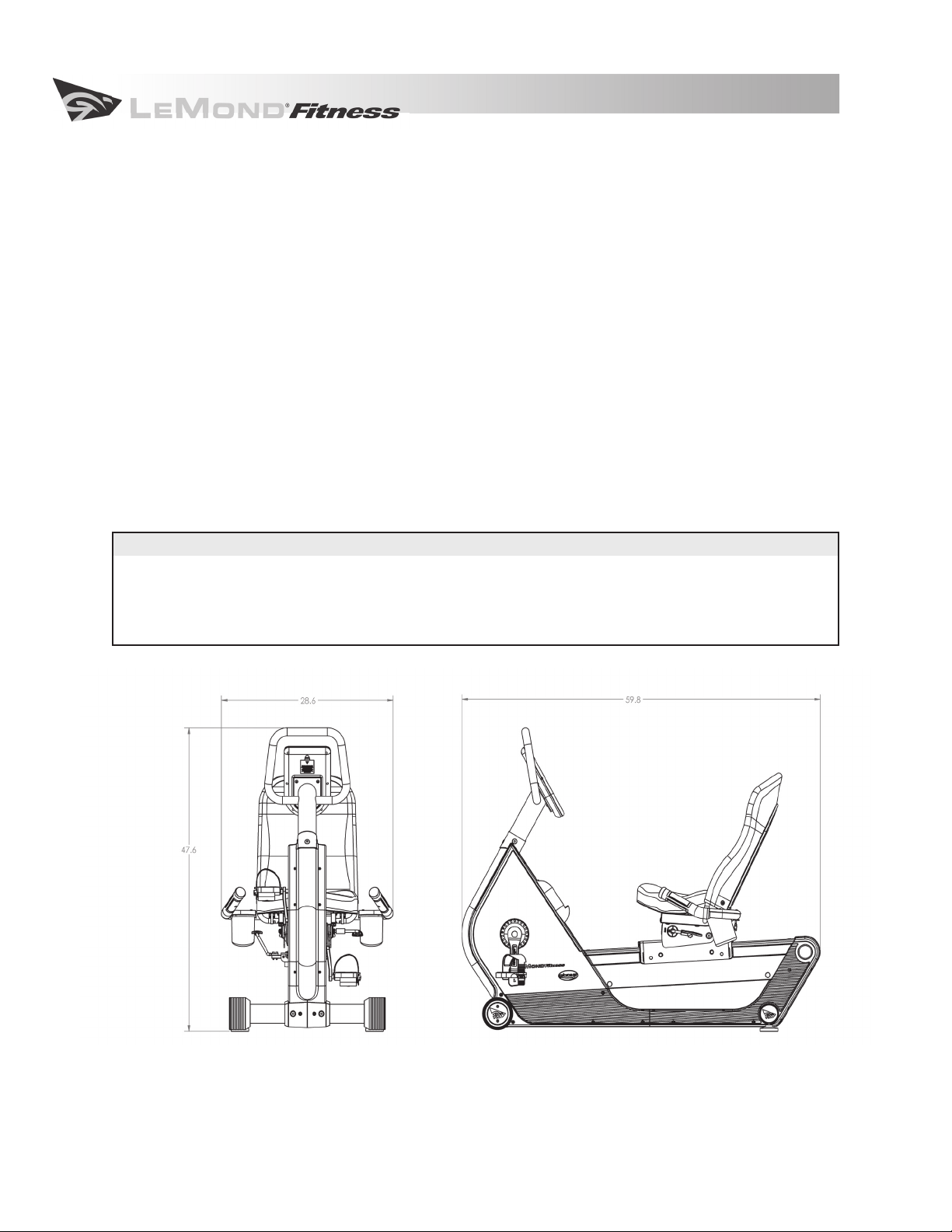
Dimensions for the assembled
g•force RT Recumbent Fitness Bike
Physical Dimensions
Length 59.8 in (151.9 cm)
Width 28.6 in (72.6 cm)
Height 47.6 in (120.9 cm)
Weight 156 lbs (70.9 kg)
8
3 ASSEMBLY AND INSTALLATION INSTRUCTIONS
3.2 Getting Started
Follow these detailed instructions to quickly assemble your new bike and you will be on the way to starting your new fitness program.
and could result in injury!
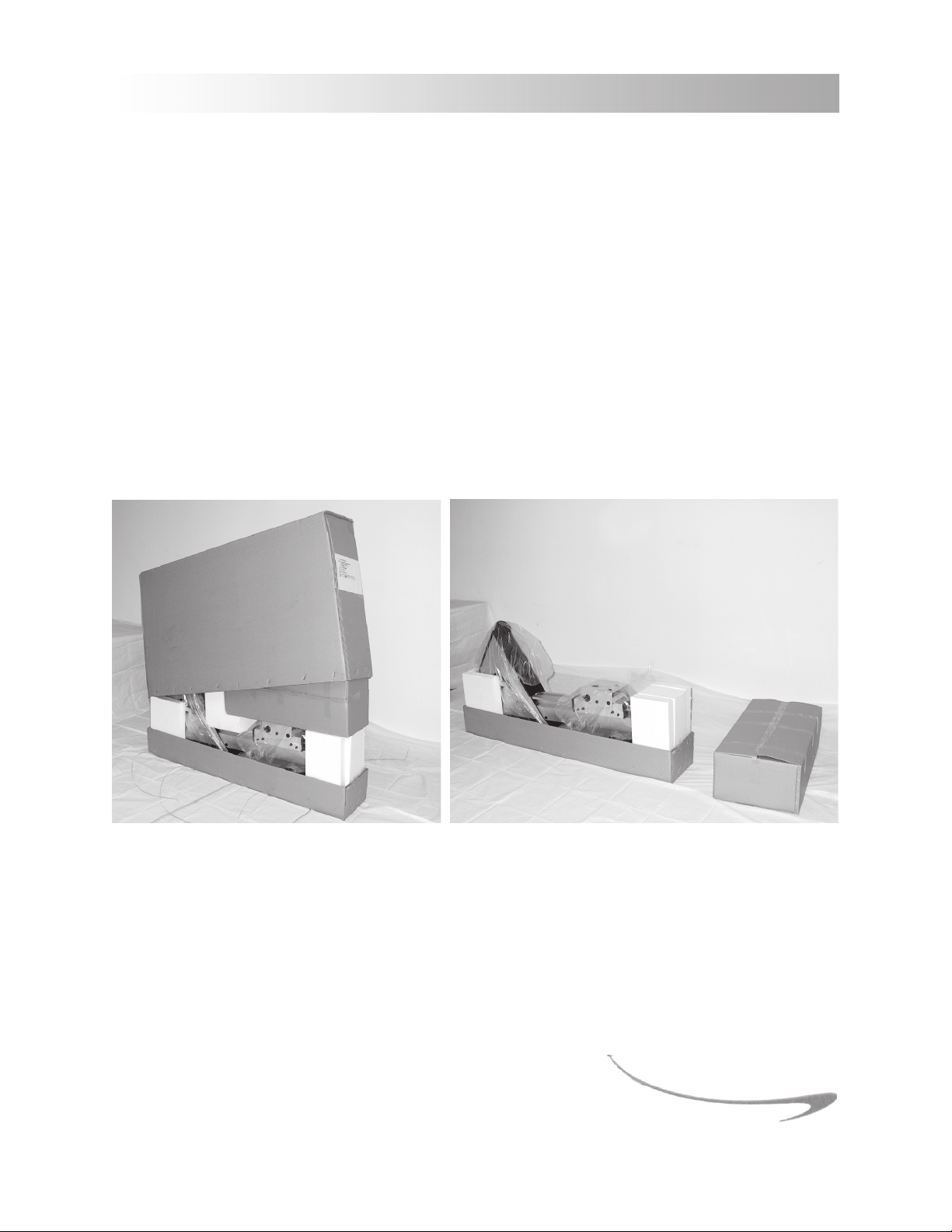
Your g•force RT will arrive in a single carton. Unpack the shipping carton in the location where the bike
will be assembled and used. Cut the shipping straps and remove the staples from the bottom edge and
then remove the top of the carton. The shipping carton contains two separate boxes and the body of the
bike.
Remove the cardboard box and the packaging materials from around the body of the bike. Unpack the
box and inspect each part thoroughly for any damage that may have occurred during shipping. Contact
the delivery carrier immediately if any damage is discovered. Contact the LeMond Fitness Customer
Service Department at (+1) 425.482.6773 between 7:00 a.m. – 5:00 p.m., M-F, Pacific time to report any
damages that have occurred during shipping.
Failure to follow these simple instructions will void your warranty
9
3 ASSEMBLY AND INSTALLATION INSTRUCTIONS
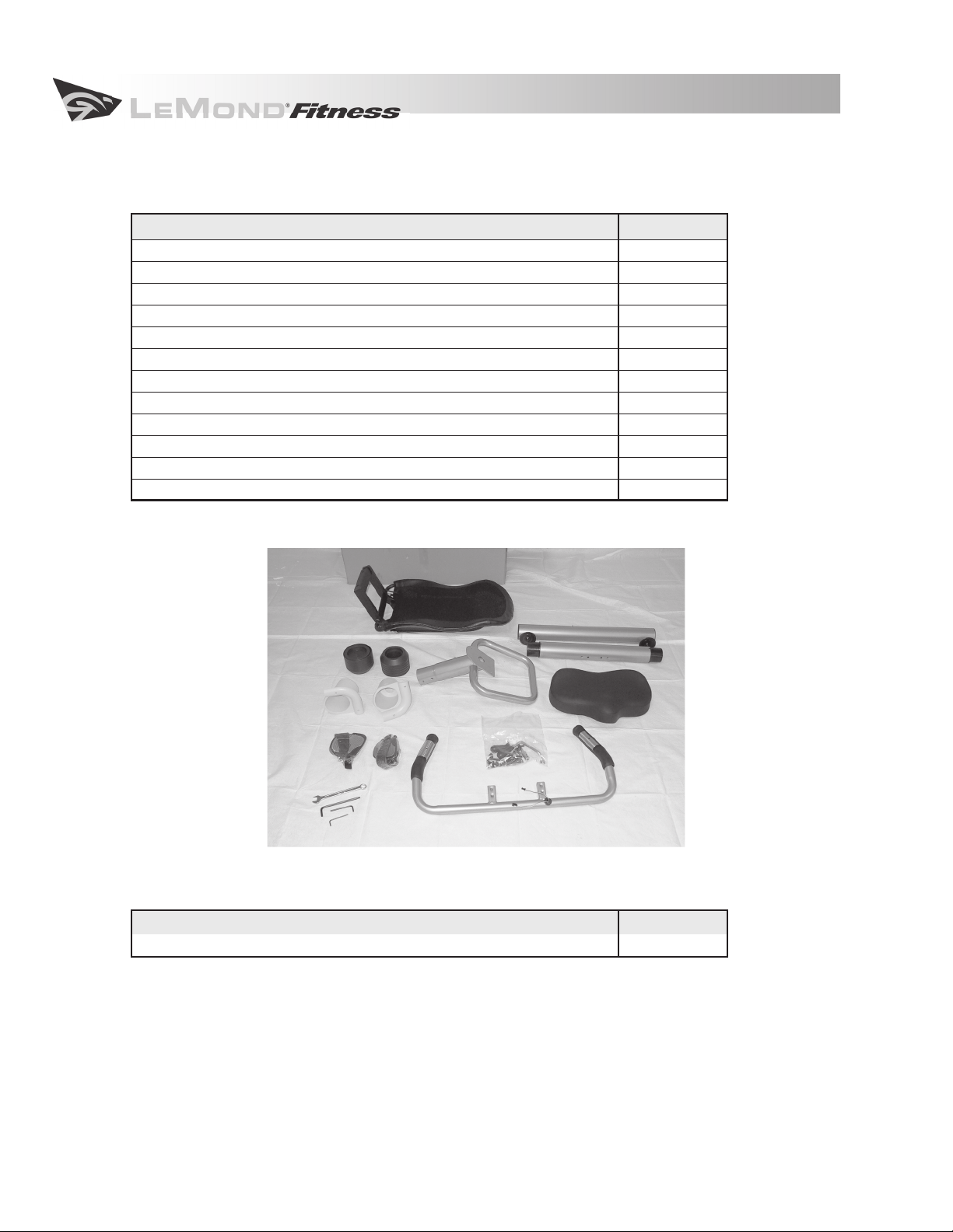
3.3 Parts
Contents of Large Cardboard Box
Part Description Quantity
Plastic bag with tools, hardware and instructions 1
Front stabilizer with one wheel attached 1
Front wheel 1
Front wheel cap 1
Rear stabilizer with one foot attached 1
Rear leveling foot 1
Seat frame 1
Seat bottom 1
Handlebar 1
Console mast 1
Pedals 2
Cup holders 2
Contents of Small Cardboard Box
Part Description Quantity
Display Console 1
3.4 Tools and Hardware
All of the tools and hardware required for the assembly of your g•force RT are included in a plastic bag
in the large box inside the main shipping carton.
10
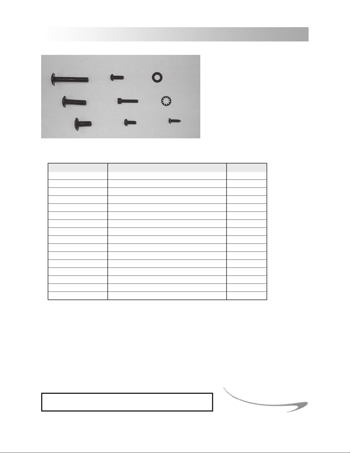
3 ASSEMBLY AND INSTALLATION INSTRUCTIONS
M8x50 M6x15 flat washer
M8x30 M5x25 star washer
M8x20 M5x15 self-tapping screw
Tools and Hardware List
Part Number Description Quantity
SA10525 M5x25 screw 2
SC10830 M8x30 screw 4
SC10615 M6x15 screw 4
SC10515 M5x15 screw 4
SC10820 M8x20 screw 9
SC10850 M8x50 screw 4
SL20515 self-tapping screw 2
W108016 flat washer 2
W308008 star washer 17
70390 fore/aft seat adjustment handle 1
70392 seat angle adjustment handle 1
70670 2.5 mm hex wrench 1
70669 3mm hex wrench 1
70668 4mm hex wrench 1
70667 6mm hex wrench 1
70671 pedal wrench 1
3.5 Assembling the Bike
The unique serial number of your g•force RT is located on the front tubing and near the bottom of the
bike. Please take a moment to find and record the serial number of your bike.
Record your serial number in the box below as well as in the PRODUCT SERVICE section. Having easy ac
cess to your serial number will help us provide you with great service more quickly should you need it.
ENTER YOUR SERIAL NUMBER IN THE BOX BELOW
-
11
3 ASSEMBLY AND INSTALLATION INSTRUCTIONS
3.5.1 Body
1. Fold down the sides of the carton base and
remove the packing material from around the
bike.
2. Leave the body of the bike on the carton base
while the remaining assembly is completed.
CAUTION: Remove the staples completely to
avoid injury.
3.5.2 Front Stabilizer
1. Locate the front stabilizer and the unattached wheel. The front stabilizer already has one wheel
attached.
2. Slide the front stabilizer into place at the front of the body frame from the left side. Rotate the
stabilizer until the set screw is positioned into the alignment notch. This will align the attachment screw holes of the body and the front stabilizer. Be careful not to dislocate the plastic
sleeve at the opposite side of the tubing. If the sleeve is pushed out of place, remove the stabilizer, replace the sleeve and reinstall the stabilizer.
3. Secure the front stabilizer by sliding star washers onto each of (2) M8x30 screws and tightening
with the 6mm hex wrench.
4. Slide the remaining front wheel onto the end of the front stabilizer and attach the wheel cap.
Use the alignment pins as a guide to install the wheel cap correctly.
5. Secure the wheel cap to the wheel with (2) self-tapping screws and tighten with the 3mm
wrench.
12
3 ASSEMBLY AND INSTALLATION INSTRUCTIONS
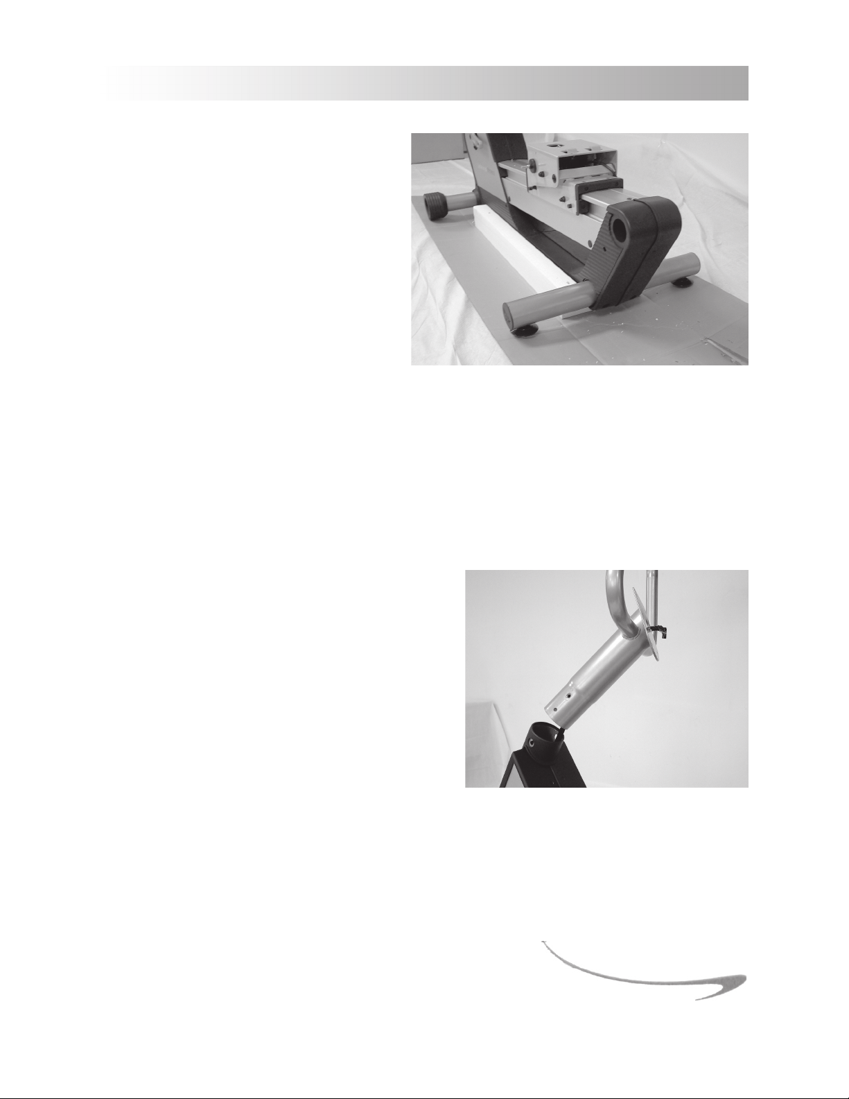
3.5.3 Rear Stabilizer
1. Locate the rear stabilizer and the leveling feet.
2. Slide the rear stabilizer into place at the
rear of the body frame from the right
side and rotate until the set screw is
positioned in the alignment notch. As
with the front stabilizer, be careful not to
dislocate the plastic sleeve.
3. Align the holes for the attachment
screws on the body and the rear stabi
lizer. Secure the rear stabilizer by sliding
star washers onto each of (2) M8x30 screws and tighten with the 6mm hex wrench.
4. Attach the leveling foot to the rear stabilizer by screwing it into the underside of the rear
stabilizer. Assume at first, that your floors are level and install each foot snugly against the rear
stabilizer.
-
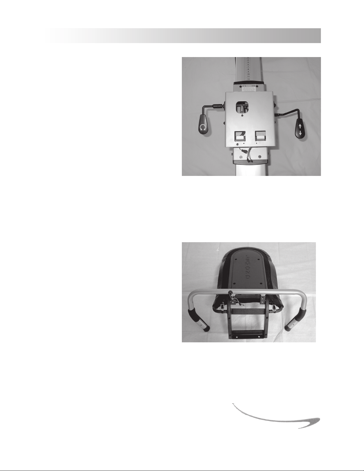
3.5.4 Display Console
Attaching the Console Mast to the Bike
1. Before installing the console mast to the body,
locate the (2) wires at the top of the front tube on
the body. Feed the wires through the tubing and
out of the hole at the top of the console mast.
2. Insert the console mast into the front tubing of
the body, taking care to align the holes for the at
tachment screws of the mast with both the body
and the plastic sleeve.
3. Secure the console mast to the body by sliding
star washers onto each of (3) M8x20 screws and
tighten with the 6mm hex wrench.
-
13
3 ASSEMBLY AND INSTALLATION INSTRUCTIONS
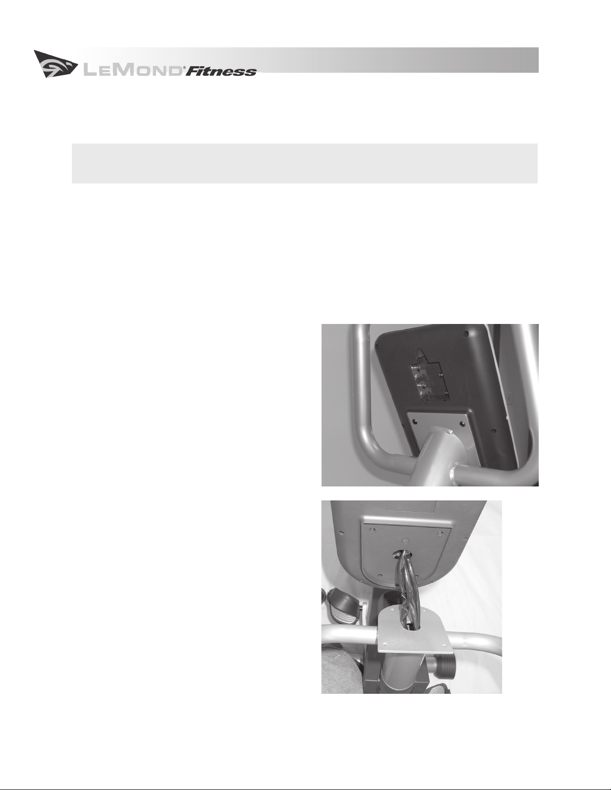
Attaching the Display Console to the Console Mast
Battery Installation
CAUTION: Never use conventional alkaline batteries. You will damage your electronic parts
and void your warranty.
The display console of the g•force RT is powered by (4) rechargeable AA nickel-metal hydride (Ni-MH)
batteries, which are included. You provide the power to recharge the batteries by simply pedaling and
working out on your bike.
1. Remove the battery compartment cover on the back of the display by pressing down on the tab
and then lifting the cover off. An illustration at the bottom of the battery compartment indicates the correct positioning of the batteries.
2. Place the batteries into the compartment as indicated on the illustration. Insert the negative
end into position first and then gently push the positive end into place.
3. Replace the battery compartment cover.
Note:
Your batteries will not be fully charged when
your bike arrives. You will need to pedal for at least 1
hour to fully charge the batteries.
Attaching the Display Console
1. Connect the wires from the console mast to
the wires on the back of the display console.
2. Once connected, gently feed the wiring into
the console mast until the display console
can rest snugly against the platform. The
platform of the console mast should fit
completely inside the grooved section of
the back of the display console.
3. Attach the display console to the console
mast using (4) M5x15 screws and tighten
with the 3mm hex wrench.
14
3 ASSEMBLY AND INSTALLATION INSTRUCTIONS
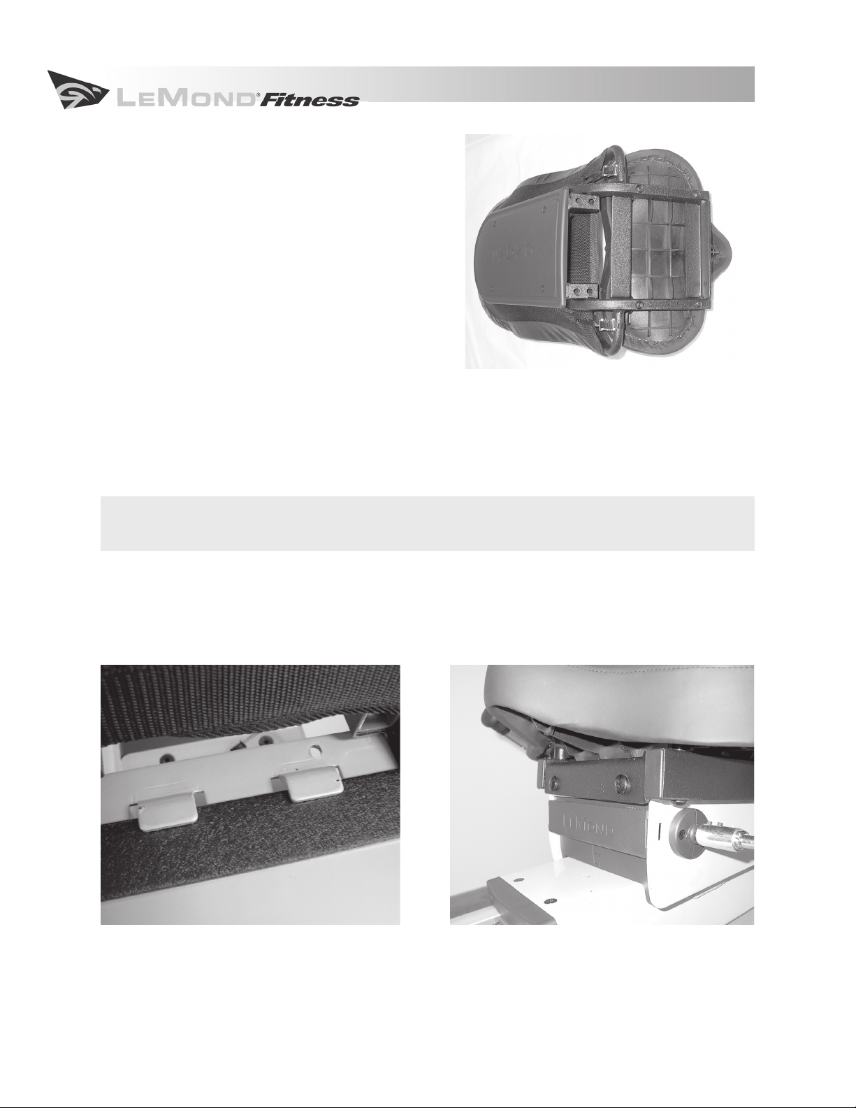
3.5.5 Seat
Attaching the Adjustment Handles to the Seat
Carrier
1. Locate the seat adjustment handles. They
can be found in the plastic bag contain
ing the tools and other hardware.
2. The shorter, L-shaped handle is attached
to the left side of the bike and controls
the seat angle adjustment. Slide the han
dle onto the post on the left side of the
seat carrier so that the set screws make
contact with the flat portion of the post.
Tighten the (2) set screws at the top of
the handle with the 2.5 mm hex wrench.
3. The longer handle controls the fore/aft adjustment of the seat and is located on the right side of
the bike. Align the (2) holes of the handle with the (2) holes on the right side of the seat carrier.
Attach the handle with (2) M5x25 screws and tighten using the 3mm hex wrench.
-
-
Attaching the Handlebars to the Seat Assembly
Attach the handlebars to the seat assembly before
attaching the seat to the body of the bike.
1. Turn the seat assembly upside down so
that the seat rails and the seat back touch
the floor.
2. Insert the handlebars into the seat as
sembly with the holes on the handlebars
facing up and aligned with the holes on
the seat carrier.
3. Secure the handlebars to the seat assem
bly by sliding (4) star washers onto each
of the (4) M8x20 screws and tighten using
the 6mm hex wrench.
-
-
15
3 ASSEMBLY AND INSTALLATION INSTRUCTIONS
Attaching the Saddle to the Seat Assembly
1. Place the seat bottom on the rails of the seat
assembly.
2. Attach the seat bottom to the seat assembly by
sliding (4) star washers onto each of (4) M8x50
screws and tighten using the 6mm hex wrench.
Attaching the Seat Assembly to the Body
Note:
Install the handlebars and seat bottom before
attaching the seat assembly to the body of the bike.
1. Locate the two tabs that are on the top surface of the seat carrier which is located on the seat
track of the body.
2. Located under the seat is a bar that runs the width of the seat. Hook the tabs of the seat carrier
over the bar on the seat assembly. (A)
CAUTION: Be careful not to pinch the wiring for the contact heart rate grips when attaching
the seat assembly to the seat carrier.
3. Lower the seat assembly over the seat carrier and align the holes at the front of the seat assembly with those on the seat carrier. (B)
4. Secure the seat assembly to the seat carrier by sliding (2) flat washers and (2) star washers onto
each of (2) M8x20 screws and tighten with the 6mm hex wrench.
16
A B
3 ASSEMBLY AND INSTALLATION INSTRUCTIONS
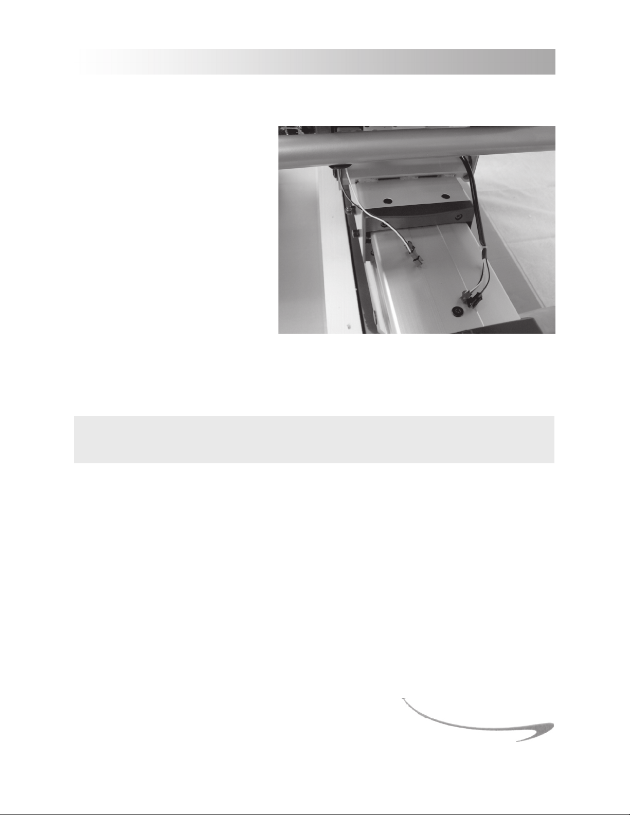
Connecting the Wiring for the Contact Heart Rate Grips
Once the seat assembly has been attached to the seat carrier, connect the two
wires on the handlebars to their corresponding wires on the seat carrier.
The connection on each of the two wires
is different. There is only one correct way
to make the connection. Do not try to
force the connection.
3.5.6 Pedals
Note:
left and right. Your pedals are marked as
such on the pedal itself.
Left and right orientation on the bike is
determined as the position you would be in while riding the bike. It is important that you attach each
pedal to the corresponding crank, as the threads on the left pedal and crank are reversed. Left pedals
are always reverse-threaded so that the pedal tightens rather than loosens while you are pedaling the
bike.
All bicycle pedals have a designated
CAUTION: Attempting to install the pedals on the incorrect side will cause damage to both
the pedal and the crank.
17

3 ASSEMBLY AND INSTALLATION INSTRUCTIONS
Attaching the Pedals to the
Crank Arms
1. Before attaching the pedals to
the cranks apply multipurpose
grease to the threads of each
pedal. Pedals that are not sufficiently lubricated will often
make a squeaking or clicking
noise with every pedal rotation
which can become an annoyance.
2. Attach the left pedal (marked L)
to the left crank. Tighten with
the pedal wrench in a COUNTER-CLOCKWISE direction.
3. Attach the right pedal (marked R) to the right crank. Tighten with the pedal wrench in a CLOCKWISE direction.
The cranks of the
systems, including the LeMond® Dual-sided Indoor Cycling Pedal.
g•force RT have 9/16-20 threads, making the bike compatible with all standard pedal
3.5.7 Cup Holders
1. Place one cup holder in each bend of the handlebars. The cup holders are marked as left (L) or
right (R) on the underside of the holder.
2. Attach the cup holders with (4) M6x15 screws and tighten with the 4mm hex wrench.
3.6 Leveling the g•force RT
Now that the bike is fully assembled, carefully lift the rear end, and roll the bike to its final location.
Check the stability of the bike by attempting to rock it from side to side. If the bike rocks or wobbles, it
should be leveled. A bike that is leveled correctly will provide a more stable and comfortable ride.
The two feet of the rear stabilizer can be adjusted to compensate for uneven floors. To level the bike,
simply raise or lower the two leveling feet by screwing them in or out as needed.
18

4 SETTING UP AND OPERATING THE g•force RT
4.1 Bike
Taking a moment to learn how to set up your g•force RT correctly will make your workouts a more
pleasant experience. The design of the g•force RT provides more seat adjustability than any other
recumbent available. Making full use of this feature will give you the most comfortable ride possible and
ensure maximum exercise efficiency. Using the bike in an incorrect position can result in unnecessary
discomfort and increase the risk of injury.
4.1.1 Seat Adjustment
To find the correct seat position for you, sit on the seat and place the ball of your foot on the center of
the pedal. Your knee should remain slightly bent when the pedal is in the farthest position away from
you. You should be able to complete the entire pedal rotation without locking the knees and without
dramatically shifting your weight from side to side.
Adjusting the Fore/Aft Position
The g•force RT is designed to be used by adults from 58 in (147.3 cm) to 80 in (203.2 cm) tall. The seat
rail has 23 locking positions to choose from.
1. Place the pedal in the forward position. Sit comfortably on the seat with the ball of your foot on
the center of the pedal.
2. If the knee is locked, move the seat forward. If the knee is bent too much, move the seat
backward.
3. To move the seat, simply pull up on the handle that is on the RIGHT side and adjacent to the
seat. With the handle held in the upward position, slide the seat forward or backward to the
correct position until it clicks into place.
4. Release the handle to its original position.
Adjusting the Seat Angle
Seat angle adjustment is a feature that is unique to the g•force RT. This adjustability allows you to find
the most comfortable riding position for your specific body type. It also offers you (5) riding positions
to fine-tune you in a way that no other recumbent bike can. Correct positioning on the bike will help
prevent over-use injuries and keep you moving forward in achieving your fitness goals.
1. To tilt the angle of the seat, simply rotate the handle that is on the LEFT side and adjacent to the
seat.
2. While holding the handle up, adjust the tilt of the seat by shifting your weight forward or back
ward until you find the most comfortable pedaling position.
3. After establishing your optimal seat angle, release the handle to its original position.
Note:
readjust the fore/aft position of the seat. Remember that your knee should not lock when the pedal is in the
most forward position.
Once you have found the seat angle position that is most comfortable for you, it may be necessary to
-
19

4 SETTING UP AND OPERATING THE g•force RT
4.1.2 Foot Positioning
For greatest pedaling efficiency, the ball of the foot should be placed over the center of the pedal. This
may feel awkward or unnatural at first, but it is to your benefit to maintain a foot position that maximizes
your exercising efficiency. After a short while, this position will begin to feel quite comfortable. Avoid
pedaling the bike with the arch of your foot centered on the pedal of the bike. Although this may seem
like a comfortable position, the arch of the foot has far less support than the ball of the foot. Pedaling for
long distances or extended periods of time with the pedal centered on the arch of the foot may cause
unnecessary pain and could lead to a more extensive injury.
As you become more familiar with your new fitness bike, you may want to consider a strapless pedal
system such as the LeMond® Dual-sided Indoor Cycling Pedal. This type of pedal has long been used by
professional and serious recreational cyclists to maximize the efficiency of their pedal stroke and keep
the foot in the correct position.
4.1.3 Pedal Strap Adjustment
The straps of the g•force RT are designed to allow you to adjust the pedal to your individual foot size.
The pedals include spring-loaded, locking clips for easy adjustments. Follow the steps below to adjust
the straps so that your foot does not slip or slide about on the pedal.
1. Place the ball of each foot on the center of the pedal and under the strap.
2. Rotate the pedals until one foot is in the position closest to you.
3. To tighten the strap, simply pull down on the end of the strap until it fits snugly over your shoe.
Make sure that the strap is secure, but not overly tight or pressing uncomfortably on your foot.
4. Repeat these steps for the other foot.
5. To loosen the pedal strap, press down at the top of the clip that holds the strap secure, and pull
the strap up. Release the clip to lock the strap into place.
Now that you have established a riding position, take a few minutes to ride the bike and confirm that
your position is comfortable. Start pedaling at a slow pace with your toes and knees pointed directly forward. Hold the grips lightly and in a position that allows your shoulders and upper body to relax. Pedal
easily at a low resistance until you feel confident that you could ride in that position comfortably for the
duration of your workout.
20

4 SETTING UP AND OPERATING THE g•force RT
4.2 Display Console
The display console of the g•force RT serves two purposes: to allow you to choose the bike’s functions,
and to provide you with feedback about the progress of your current workout.
Always use a light touch when pressing keys on the console overlay. Never press the keys with any-
Note:
thing other than your fingers. Sharp objects such as ball point pens, keys or tools could damage the overlay
and are considered misuse for warranty purposes.
4.2.1 Display Console Features
Power:
button, but the easiest way to power up the display console is to simply start pedaling.
Quick Start:
parameters.
Note:
target heart rate.
Stop:
pause the program. To restart the program where you left off, simply press ENTER. Pressing the STOP
key twice will end the program and the MESSAGE DISPLAY will show the data accumulated during your
workout. Pressing the STOP key three times will return you to the SELECT WORKOUT prompt.
Enter:
Pressing the ENTER key will confirm the value you have chosen and move you to the next step in setting
up your program.
Back:
+/- Keys:
or decrease values such as weight, or age. While a defined program is running, the +/- KEYS are used to
increase or decrease resistance.
Turns the display console on or off. You can start the display console by pressing the POWER
This key overrides the need to enter user data and starts a selected program with default
This function can not be used in the Constant HR program. User data is required to establish your
This key is only effective while a DEFINED PROGRAM is running. Pressing the STOP key once will
Press this key when prompted by the MESSAGE DISPLAY to enter values such as time or weight.
Use this key to return to the previous screen on the MESSAGE DISPLAY.
These keys serve two functions. While setting up a program, the +/- KEYS are used to increase
+ Key:
fined program is running, use this key to increase the resistance level – making the workout harder.
- Key:
fined program is running, use this key to decrease the resistance level – making the workout easier.
Note:
on the PROFILE DISPLAY.
Message Display:
program workouts. Simply answer the prompts that are given on the screen to start any of the eleven
DEFINED PROGRAMS.
While setting up a program or a profile, use this key to increase a numeric value. While a de-
While setting up a program or a profile, use this key to decrease a numeric value. While a de-
You can press these keys repeatedly or, simply touch and hold the key until the desired value appears
This LCD display will guide you through the steps to set up your user profiles and the
21

4 SETTING UP AND OPERATING THE g•force RT
Profile Display:
When setting up a program, the PROFILE DISPLAY will show values, such as age and weight, that you
will be asked to modify. Use the + or - keys to increase or decrease the default value that is shown in the
PROFILE DISPLAY.
Once a program is started, the PROFILE DISPLAY will show your progress through out the workout by
showing the segments of a workout that you are about to complete or have already completed. It also
shows the resistance level for each segment.
Each column in the PROFILE DISPLAY represents a specific segment of the workout. Your progress is
represented by the blinking column. Each row represents the resistance level at that segment. There
are 20 levels of resistance in the g•force RT. Each row in the PROFILE DISPLAY represents two levels of
resistance. A dimly lit row represents that you are on the easier of the two resistances in that level.
Feedback Displays:
ries you are expending, as well as physical information such as the time you have spent working out and
the number of miles you have traveled in your living room.
Distance/HR:
Distance:
HR:
contact heart rate grips with both hands, or by wearing a heart rate transmitter chest strap.
This 10x16 LED matrix screen has two functions.
These displays show you physiological information such as heart rate and the calo-
Toggles between DISTANCE and HR values.
The total DISTANCE traveled in miles.
The detected HEART RATE in beats per minute. HEART RATE is detected by holding the
Note:
can affect the accuracy of your heart rate reading. The heart rate function of the g•force RT should not be
considered or used as a medical device.
Time/RPM:
Time:
RPM:
kCal/Watts:
kCal:
Note: The WATT is a measurement of workload. It is affected by both resistance and pedal speed. Increased
resistance and increased pedal rate increases the number of WATTS expended. This information can be used
to evaluate your fitness progress over time. As your fitness improves, your WATTS expenditure for a given
program should decrease.
The heart rate function of the g•force RT is intended only for use as an exercise aid. Various factors
Toggles between TIME and RPM values.
The amount of TIME remaining in your workout. Shown in minutes:seconds.
Keeps track of your pedal speed in revolutions per minute (RPM).
Toggles between kCAL and WATTS values.
The approximate number of CALORIES burned since the beginning of the workout.
Watts:
The approximate power that is being expended while pedaling the bike.
22

4 SETTING UP AND OPERATING THE g•force RT
Defined Programs:
esting, including some of Greg LeMond’s favorite workouts (located in the Lemond Training Program)
that he uses for race preparation which are located in the LEMOND TRAINING program.
1 Manual
2 Hill
3 Fat Burner
4 Race
5 Constant HR
6 LeMond Training
Rev-it-Up
Pump the Power
Bust your Gut
Strong & Steady
Peak Power
Race Day
Profile 1,2,3:
programs. This information is the data that is needed to accurately calculate feedback functions such as
your caloric expenditure and the watts measurement.
Often, the toughest, but most important step, of any exercise program is simply getting started. By pur
chasing the g•force RT, you have already achieved what many people are still struggling with — making the commitment to leading a more fulfilling life by including a program of physical activity.
Allows up to three users to program personal information to be used in the workout
A variety of workouts that allow you keep your exercise program varied and inter-
-
Congratulations on accomplishing the first step towards a healthier and more satisfying future.
23

5 GUIDELINES FOR AN EFFECTIVE EXERCISE PROGRAM
Setting a Goal and Defining Objectives
An important step in a successful exercise program is to set achievable goals and objectives. Regardless
of your current physical condition, you need to establish a workable plan to reach your fitness goals.
Begin by asking yourself a few basic questions. Are you just beginning an exercise program and wishing
to change your lifestyle from sedentary to physically active, or are your goals to enhance your current
fitness levels? What are your primary objectives? Is your program to be geared toward losing weight,
increasing aerobic capacity, maintaining or building muscle tone, or perhaps all three?
In order to ensure that you fully receive all benefits associated with a sound exercise program, you
should first identify any risk factors that may influence the design of your exercise program. Your health
care professional should be the first step in identifying risk factors that may need to be addressed in establishing a program. Consider having a trained fitness professional help you in developing an individualized program that is enjoyable, easily maintained, but still challenging enough to achieve your desired
results.
Remember that your greatest benefit will come from an increased sense of well-being that comes along
with a lifestyle that includes physical activity. People who have already made physical fitness a part of
their daily lives, will confirm that the benefits of including physical activity in your life far outweigh the
inconvenience and time spent.
Any time you spend on your exercise program will reward you with increased energy, reduced stress, a
greater ability to focus and concentrate, and improved self-confidence. You and the people you share
your life with will reap the rewards of your new lifestyle.
Flexibility Training
Achieving and maintaining an adequate range of motion should always be included in a comprehensive
exercise program. Sufficient flexibility will increase your enjoyment and maximize the effectiveness of
exercising on the g•force RT. It will also reduce discomfort while working out and reduce the risk of
injury. Always warm-up before stretching. Warm-up should include light activity to increase both your
heart rate and body temperature. Increasing your body temperature allows you to stretch muscles
more effectively and safely. Attempting to stretch a cold muscle is counterproductive and can lead to an
injury that may interfere with the continuation of your fitness program and can postpone reaching your
goals.
24

5 GUIDELINES FOR AN EFFECTIVE EXERCISE PROGRAM
Guidelines for Exercising on the g•force RT
Warming Up
A good warm-up is one of the most important and most frequently overlooked part of an exercise regimen. Without a proper warm-up, the muscles of the body are far more prone to injury. A good warm-up
prepares the body for the stress you will place your muscles under during your workout and will decrease your chances of becoming injured. Muscles perform better when they are warmer than normal
body temperature. Always take the time to warm-up properly. It will decrease the discomfort during
exercise and will help you get the most out of your workout.
While a 5 to 10 minute warm-up is adequate for some people, others may need a longer warm-up period
to be physiologically ready for intense efforts. Because different people have different requirements for
an adequate warm-up, the workouts in the
This allows you to warm up for a period of time and at a resistance level that is appropriate for you.
Take the time to learn what your personal requirements are for warming up. Pedal slowly and at a low
resistance at first, gradually increasing your pedal speed until you feel the muscles in your legs begin to
relax. Slowly increase your heart rate to about 110-120 beats per minute. Once you have warmed up
sufficiently, begin your workout. Your workout will be more enjoyable and more productive
g•force RT, do not include a specific warm-up segment.
Frequency
How often should you exercise? The number of times per week that you engage in aerobic exercise
depends largely on what your goals are and your current fitness level. People new to an active lifestyle
are more likely to keep with it if they start gradually. Beginners might consider a weekly schedule that
includes days off. Seasoned athletes may workout almost every day, but even these athletes know that
easy days are essential for muscular and mental recovery. Work towards a goal of including exercise at
least 3 to 5 days per week.
Intensity
How hard should you exercise? Again, the intensity of your workout will reflect your goals and your
current fitness level. To achieve the greatest cardiovascular benefit, and to see the most improvement in
weight loss and physical tone, you must raise your heart rate into your target zone. Your target zone is
generally between 55 to 85% of your maximum heart rate. Training in this zone is what is referred to by
exercise scientists as ‘aerobic exercise’. The CONSTANT HR program in the g•force RT is programmed
to help you exercise in the middle of this zone by maintaining your heart rate at 70% of you maximum
heart rate.
25

5 GUIDELINES FOR AN EFFECTIVE EXERCISE PROGRAM
Duration
How long should you exercise? You should aim to complete 20 to 60 minutes of continuous activity in
your aerobic exercise zone. Keep in mind that this does not include warm-up or cool-down. A 30 minute
workout with 10 minutes warm-up and 10 minutes cool-down, five days a week, will result in noticeable
improvement in physical conditioning.
Cool-down
Just as the warm-up is essential for preparing your muscles for vigorous exercise, the cool-down is equally important. It is tempting to simply stop pedaling as soon as you have finished your programmed
workout. You will reap greater rewards from your workout, however, if you consistently take the time for
a proper cool-down. This process is important in allowing your body’s cardiovascular system to gradually return to normal. It also allows your muscles to begin the process of recovery which will make your
next workout easier.
Over 5 to 10 minutes, gradually lower your heart rate to below 110 beats per minute by slowly decreasing your exercise intensity.
Taking the time to warm-up and cool-down properly will decrease the level of discomfort you will experience when you tackle your next workout. More importantly, though, proper warm-up and cool-down
segments will greatly decrease your risk of injury.
Most importantly:
commitment and you researched, chose, and bought the equipment to make your goals become reality.
Now it’s up to you. Remember that all of the guidelines you just read are just that – guidelines. If a 30
minute workout is too much for your current fitness level, choose a duration that you can complete and
gradually increase your time. Any increase in the amount of physical activity over what you are currently
doing, is a step forward.
Remember that even the most conditioned and dedicated athletes have days in which they slip from
their training plans, make poor nutritional choices, or quit in the middle of a workout. If you find yourself in such a situation, think about the progress you had made previously, reevaluate your training plan,
and recommit to your goals. Keep in mind the story of Greg LeMond who came back from a near fatal
injury to win the most famous bike race in the world - not just once but twice. He too had to start over
one step at a time.
Stick with your program! You already accomplished the hard part. You made the
26

6 PROGRAM PROFILES
Custom User Profiles
The PROFILE [1, 2, or 3] keys on the g•force RT allow three different users to enter and store personal
information for weight, age, target heart rate, and intensity level. These specifics can be quickly entered
and stored when setting up a defined program. A custom PROFILE may also be changed at a later date
to reflect changes in your age or weight.
Defined Programs
The g•force RT has eleven different workouts programmed into the console. Each PROGRAM provides
different benefits and can help you achieve your own personal fitness goals, be it weight loss, increasing endurance, or improving your aerobic threshold. The variety of programs allows you to use your
g•force RT for very different aspects of your fitness program. Seasoned athletes know that varying
your routine is essential to success. A tough day of interval training or a challenging hill workout is best
followed by an easy day that allows your body to recover from the previous days efforts.
For example, you can choose a challenging workout such as a RACE against Greg LeMond on a Tuesday,
and then do a less intense, recovery ride with the CONSTANT HR workout on the following day.
These programs allow you to vary your workouts and provide you with fun and challenging ways to
jumpstart you fitness program and reach your fitness goals faster. Having a variety of programs available
to you, keeps you from becoming bored with your daily workout routine and more likely to stick with
your fitness plan.
1 Manual
The simplest program in the g•force RT, the MANUAL program provides a workout with a constant
resistance and a time limit that you specify. At any time during the workout you can increase or decrease the resistance using the + or - keys.
We recommend that you use this program to become familiar with the bike and the resistance functions.
MANUAL PROGRAM
Increments
Intensity
Level
%
1 2 3 4 5 6 7 8 9 10 11 12 13 14 15
100
90
80
70
60
50
40
30
20
10
27

6 PROGRAM PROFILES
2 Hill
The HILL workout is designed to increase your strength as you pedal up and over four resistance hills of
varying steepness and distance.
HILL PROGRAM - RESISTANCE INTERVALS
30 MINUTE WORKOUT
1 MINUTE INCREMENTS
Increments
3 Fat Burner
The FAT BURNER program is a challenging workout with several intervals of increased resistance. The
program is specifically designed to optimize your workout for weight loss.
1 2 3 4 5 6 7 8 9 10 11 12 13 14 15 16 17 18 19 20 21 22 23 24 25 26 27 28 29 30
100
90
80
70
60
50
40
30
20
10
FAT BURNER PROGRAM
30 MINUTE WORKOUT
1 MINUTE INCREMENTS
Increments
Intensity
Level
%
1 2 3 4 5 6 7 8 9 10 11 12 13 14 15 16 17 18 19 20 21 22 23 24 25 26 27 28 29 30
100
90
80
70
60
50
40
30
20
10
4 Race
Test your fitness against Greg’s! The RACE program is a simulated competition between yourself and
Greg LeMond. In the PROFILE DISPLAY a circle of lights represents your progress throughout the race.
The inside circle of lights represents Greg and the outside circle of lights represents you. The flashing LED
represents the ‘racer’. See if you can overtake Greg during your workout and win the race.
RACE PROGRAM
INNER CIRCLE - COMPUTER; OUTER CIRCLE - USER
Increments
Intensity
Level
%
1 2 3 4 5 6 7 8 9 10 11 12 13 14 15
100
90
80
70
60
50
40
30
20
10
28

6 PROGRAM PROFILES
5 Constant HR
The CONSTANT HR workout is programmed to help you maintain a chosen target heart rate by automatically changing the level intensity during your workout.
CONSTANT HR PROGRAM
Increments
Intensity
Level
%
Note:
This program is an easy way to keep you from becoming lazy during your workout. It is also a good
program to make sure that you are not working too hard during a recovery ride.
1 2 3 4 5 6 7 8 9 10 11 12 13 14 15
100
90
80
70
60
50
40
30
20
10
The CONSTANT HR program requires the use of a heart rate transmitter chest strap.
The target heart rate that the computer chooses for you is based on the age you have entered during
the set up of the program. The value of your target heart rate for this program is 70% of your theo
retical maximum heart rate. For example, the theoretical maximum heart rate for a 40 year-old is 180
bpm. The target heart rate of 70% is 126 bpm.
When setting up the CONSTANT HR program the MESSAGE DISPLAY will ask you to enter your age.
Once your age has been entered the console will calculate your target heart rate and display it on the
PROFILE DISPLAY. At this point you can change your target heart rate with the +/- Keys and then press
ENTER to accept.
The minimum target heart rate that you will be allowed to ENTER is 80. The maximum target heart
rate is 200.
6 LeMond Training
Within this program are six different workouts specifically designed by Greg LeMond, which he uses
for race preparation. Each workout has a specific purpose in his, and in your, training plan. Use these
workouts for your own race preparation, and then test your progress by challenging Greg in a RACE
program.
Rev-it-Up
Pump the Power
Bust Your Gut
Strong and Steady
Peak Power
Race Day
29

6 PROGRAM PROFILES
Setting Up and Running the Programs
The easiest way to set up and run the programs in the display console, is to simply enter data as asked
for by the MESSAGE DISPLAY. The prompts in the MESSAGE DISPLAY are simple messages that guide you
through the program set up. The following is a detailed description of the same messages that are asked
of you in the MESSAGE DISPLAY.
Custom User Profiles
The PROFILE [1, 2, or 3] keys on the g•force RT allow three different users to enter and store personal
information for weight, age, target heart rate, and intensity level. These specifics can be quickly entered
when setting up a defined program by simply pressing your personal PROFILE at the PROMPT.
Don’t cheat! Enter your current weight, not the weight you intend to be. By giving the console correct
information, it can more accurately calculate the calories and Watts that you’ve actually expended during a workout. Keep in mind that a person with a greater body weight actually burns more calories per
hour at the same effort than a person who weighs less.
Entering Weight:
Your current body weight is used to calculate your caloric expenditure. After selecting a PROFILE, the
MESSAGE DISPLAY will prompt you to enter your weight. Use the + or – keys to change the default
weight of 180 that is shown in the PROFILE DISPLAY. When your current weight is displayed in the PROFILE DISPLAY, press the ENTER key.
Entering Age:
Your current age is used to calculate your target heart rate. Use the + or – keys to change the default age
of 40 that is shown in the PROFILE DISPLAY. When your correct age is displayed in the PROFILE DISPLAY,
press the ENTER key.
Choosing a Target Heart Rate:
You may wish to change the target heart rate that the console calculates for you based on the age you
entered in the previous step. The console automatically generates a target heart rate that is 70% of your
theoretical maximum heart rate. You may wish to increase or decrease your target heart rate. To do so,
simply change your calculated target heart rate that is displayed in the PROFILE DISPLAY, using the + or
– keys. Once the desired target heart rate is displayed, press the ENTER key.
30

6 PROGRAM PROFILES
Defining a USER PROFILE
Entering data for a custom USER PROFILE can be accomplished at two different stages. The parameters
can be entered before a DEFINED PROGRAM has been selected, or during the initial set-up of a DEFINED
PROGRAM.
To enter and store data before running a program, follow these steps:
1. At the SELECT WORKOUT prompt, enter one of the three PROFILE keys. The MESSAGE DISPLAY
will then prompt you to enter values for: weight, age, target heart rate, and intensity level. De
fault values for each of these are displayed on the PROFILE DISPLAY. Change the value with the
+/- KEYS and then press ENTER for each parameter.
-
2. Once the values have been entered for each parameter in the PROFILE option, you will be re
turned to the SELECT WORKOUT prompt on the MESSAGE DISPLAY. The values you have entered
have now been stored.
To enter and store data after a program has been selected, follow these steps:
1. At the SELECT WORKOUT prompt, choose any of the DEFINED PROGRAMS by pressing the cor
responding key, and then pressing the ENTER key. The MANUAL program is a good one to start
with.
2. Once the program has been entered, the MESSAGE DISPLAY will ask you to ENTER PROFILE.
Select a PROFILE [1, 2, or 3]. If no data has been previously entered for that profile, the DISPLAY
PROMPT will guide you through set up of the profile. Remember that the default values are
shown in the PROFILE DISPLAY screen. Use the + and – keys to change the default data.
3. After the parameters have been entered, they are stored under the PROFILE number that you
initially chose.
A USER PROFILE can be changed at a later time to reflect the results of your fitness program, such as
weight loss, or the inevitable aging process. A stored USER PROFILE can only be changed before a DE
FINED PROGRAM has been selected.
1. At the SELECT WORKOUT program enter the PROFILE number you wish to change.
2. The values previously stored will be shown in the PROFILE DISPLAY. Change the desired param
eters with the + or - keys as the MESSAGE DISPLAY guides you through the process.
-
-
-
-
31

6 PROGRAM PROFILES
Running the Defined Programs
Once you have become comfortable with the DISPLAY CONSOLE, take the following steps to run a
DEFINED PROGRAM and begin your exercise routine in earnest. Remember that the messages in the
MESSAGE DISPLAY will quickly and easily get you started with your workout.
1. Begin pedaling until you see the SELECT WORKOUT prompt, in the MESSAGE DISPLAY
2. Choose a workout from the six keyed programs and press ENTER when asked to confirm the
program you have chosen.
3. If you have already set up a USER PROFILE, press the key for which you have entered information
for your PROFILE and then press ENTER.
4. If you have not set up a PROFILE, the MESSAGE DISPLAY will guide you through the necessary
steps.
Note:
You can also skip setting up a personal profile by simply pressing the QUICK START key which
will immediately start your chosen program running with the default parameters. Using the default
program, you are a 180 pound, 40 year-old male. Keep in mind that physiological data in the FEEDBACK DISPLAY is only accurate when you have entered in your profile accurately.
Remember that you cannot use the QUICK START key with the CONTINUOUS HR program, be-
cause user data is required to establish your target heart rate zone.
5. Once a PROFILE has been selected or defined, the MESSAGE DISPLAY will ask you to select a
length of time for your workout. Using the + or – keys, select a length of time between 5 and 99
minutes. Press the ENTER key to select the duration.
Ending a Defined Program
The best way to end a defined program is to finish your workout. Once the time you have selected for
your workout has elapsed. The MESSAGE DISPLAY will then display the statistics from workout you have
just completed.
You can also end a workout by simply pressing the STOP key. Pressing this key once will pause your
workout. Press ENTER to resume your workout where you left off, or press STOP again to end your workout. Pressing STOP for a third time will bring you back to the SELECT WORKOUT prompt.
Once a program has paused, if no action is taken and the bike is at rest, the display console will automatically shut off after two minutes of inactivity.
32

6 PROGRAM PROFILES
LeMond Training Programs
Within the LeMond Training Program are six different workouts specifically designed by Greg LeMond,
which he uses for race preparation. The set up of these programs is identical to the other DEFINED
PROGRAMS in the g•force RT, with one exception – the duration of the workout is fixed and cannot be
changed.
All of the workouts are 30 minutes in duration.
These are challenging workouts that are a mix of aerobic and anaerobic efforts. Make sure that you have completed a proper warm-up before undertaking
these programs. The programs will be far easier to complete if your muscles are sufficiently prepared.
Setting up and Running the LeMond Training Programs
1. To run one of the six workouts in the LeMond training program, first select LEMOND TRAINING at
the SELECT WORKOUT prompt.
2. After pressing ENTER you will be prompted to SELECT PROGRAM. Using the + or - keys, scroll
through the six different programs and select your program by pressing ENTER.
3. Once a program has been entered the MESSAGE DISPLAY will guide you through set up of the
chosen program as is done in any of the other DEFINED PROGRAMS, with the exception of dura
tion. All LeMond training programs are a fixed duration of 30 minutes.
4. If no program is chosen at the SELECT PROGRAM prompt, by default you will be started on the
REV IT UP program.
Rev-it-Up:
REV-IT-UP - ANAEROBIC INTERVAL
30 MINUTE WORKOUT
20 SEC INCREMENTS
1 2 3 4 5 6 7 8 9 10 11 12 13 15 15
Increments
Intensity
Level
%
1 2 3 4 5 6 7 8 9 10 11 12 13 14 15 16 17 18 19 20 21 22 23 24 25 26 27 28 29 30 31 32 33 34 35 36 37 38 39 40 41 42 43 44 45
100
90
80
70
60
50
40
30
20
10
-
Increments
Intensity
Level
%
REV-IT-UP - ANAEROBIC INTERVAL
30 MINUTE WORKOUT
20 SEC INCREMENTS
16 17 18 19 20 21 22 23 24 25 26 27 28 29 30
46 47 48 49 50 51 52 53 54 55 56 57 58 59 60 61 62 63 64 65 66 67 68 69 70 71 72 73 74 75 76 77 78 79 80 81 82 83 84 85 86 87 88 89 90
100
90
80
70
60
50
40
30
20
10
33

6 PROGRAM PROFILES
The REV-IT-UP program is designed to increase your maximum power output. Low intensity, recovery
segments are punctuated by short but extremely high intensity intervals. Designed to increase your
top end, this workout will give you speed and power to spare!
Pump the Power:
This challenging workout is designed to develop greater strength and endurance. Higher intensity anaerobic efforts of varied duration are followed by moderate intensity recovery segments. A sure winner
for those who want to see results fast.
PUMP THE POWER - ANAEROBIC INTERVALS
30 MINUTE WORKOUT
15 SEC INCREMENTS, 30 & 45 SEC INTERVALS
1 2 3 4 5 6 7 8 9 10 11
Increments
Intensity
Level
%
1 2 3 4 5 6 7 8 9 10 11 12 13 14 15 16 17 18 19 20 21 22 23 24 25 26 27 28 29 30 31 32 33 34 35 36 37 38 39 40 41 42 43 44 45
100
90
80
70
60
50
40
30
20
10
12 13 14 15 16 17 18 19 20 21 22
46 47 48 49 50 51 52 53 54 55 56 57 58 59 60 61 62 63 64 65 66 67 68 69 70 71 72 73 74 75 76 77 78 79 80 81 82 83 84 85 86 87 88 89 90
23 24 25 26 27 28 29 30
91 92 93 94 95 96 97 98 99 0 1 2 3 4 5 6 7 8 9 10 11 12 13 14 15 16 17 18 19 20
34

6 PROGRAM PROFILES
Bust Your Gut:
This workout tests all aspects of your fitness. 60 second high intensity efforts are followed by three
minute recovery periods of moderate intensity. Those three minutes might feel pretty short by the end
of this 30 minute workout. This program will do wonders for your strength, power, endurance, and, of
course, your waistline.
BUST YOUR GUT - ANAEROBIC INTERVAL
30 MINUTE WORKOUT
1 MINUTE INCREMENTS, 3 MIN RECOVERY, 6 INTERVALS
Increments
Intensity
Level
%
1 2 3 4 5 6 7 8 9 10 11 12 13 14 15 16 17 18 19 20 21 22 23 24 25 26 27 28 29 30
100
90
80
70
60
50
40
30
20
10
Strong and Steady:
This workout focuses on building aerobic capacity. Combining moderate intensity efforts with low
intensity recovery segments, aerobic strength and fat metabolism are the main objectives. Just a couple
of STRONG AND STEADY workouts a week will have you looking leaner and breathing easier in no time.
STRONG AND STEADY - AEROBIC INTERVAL
30 MINUTE WORKOUT
1 MINUTE INCREMENTS, 5 MIN STEADY STATE, 5 MIN RECOVERY, 3 INTERVALS
Increments
Intensity
Level
%
1 2 3 4 5 6 7 8 9 10 11 12 13 14 15 16 17 18 19 20 21 22 23 24 25 26 27 28 29 30
100
90
80
70
60
50
40
30
20
10
35

6 PROGRAM PROFILES
Peak Power:
In this program you will complete an ‘aerobic ladder’. Starting at a low intensity, you will gradually climb
to a moderate intensity level and then gradually work your way back down. This is a great program to
alternate with STRONG AND STEADY to enhance fat metabolism and improve aerobic capacity.
PEAK POWER - ANAEROBIC INTERVAL
30 MINUTE WORKOUT
30 SEC INCREMENTS
1 2 3 4 5 6 7 8 9 10 11 12 13 14 15 16 17 18 19 20 21 22
Increments
Intensity
Level
%
1 2 3 4 5 6 7 8 9 10 11 12 13 14 15 16 17 18 19 20 21 22 23 24 25 26 27 28 29 30 31 32 33 34 35 36 37 38 39 40 41 42 43 44 45
100
90
80
70
60
50
40
30
20
10
23 24 25 26 27 28 29 30
46 47 48 49 50 51 52 53 54 55 56 57 58 59 60
36

6 PROGRAM PROFILES
Race Day:
A great workout for ‘active recovery’ rest days or as a warm up for races, ball games or a hard weightlifting session. With several bursts of hard efforts in the beginning, and finishing with an extended tempo
segment, you’ll be ready for your next power workout.
RACE DAY
30 MINUTE WORKOUT
30 SEC INCREMENTS
1 2 3 4 5 6 7 8 9 10 11
Increments
Intensity
Level
%
1 2 3 4 5 6 7 8 9 10 11 12 13 14 15 16 17 18 19 20 21 22 23 24 25 26 27 28 29 30 31 32 33 34 35 36 37 38 39 40 41 42 43 44 45
100
90
80
70
60
50
40
30
20
10
12 13 14 15 16 17 18 19 20 21 22
46 47 48 49 50 51 52 53 54 55 56 57 58 59 60 61 62 63 64 65 66 67 68 69 70 71 72 73 74 75 76 77 78 79 80 81 82 83 84 85 86 87 88 89 90
23 24 25 26 27 28 29 30
91 92 93 94 95 96 97 98 99 0 1 2 3 4 5 6 7 8 9 10 11 12 13 14 15 16 17 18 19 20
37

6 PROGRAM PROFILES
A Few Additional Tips about the Functions of the Display Console:
• You can easily change the resistance level of a workout after the program is running. Using the +
or – keys, increase or decrease the resistance to suit your needs. Doing so changes the resistance
throughout all segments of the program.
• The duration of a workout can be changed before a program begins running but not during the
program. To change the duration once a program is running, you will need to exit the program and
restart it after entering in the desired duration.
• During a workout, the MESSAGE DISPLAY will scroll through the statistics of your current workout.
• At the completion of a workout, the MESSAGE DISPLAY will summarize statistical information from
the workout you have just completed such as total distance, and total time. These statistics are also
displayed if the workout has been ended prematurely.
• Pressing STOP during a program will pause the program. To restart the workout, simply press ENTER
and the workout will resume at the segment that it was paused. If no action is taken within 15 seconds of a program being paused, the display console will switch to a resting mode. After two minutes
the display console will turn itself off.
• If you stop pedaling during a workout, the display console will behave in the same manner as if you
had pressed the STOP key.
• You can change the units that distance is measured in from miles to kilometers (km), by pressing the
ENTER, BACK and MANUAL keys simultaneously. Use the + or – keys to toggle between UNITS USA
(miles) and UNITS METRIC (km).
g•force RT was designed to be an attractive, effective and safe method for realizing your fitness
The
goals. Durable and high performance components were a key design feature of the g•force RT. The
safety level achieved by the design, however, can only be maintained when the equipment is regularly
examined for damage and wear. Inoperable or worn components should be replaced immediately and
the equipment should be put out of use until it is repaired. Read all maintenance instructions thoroughly before beginning work. Maintenance is the sole responsibility of the owner.
Initial Service
Choosing a cool and dry location for the g•force RT will extend the lifetime of the equipment and increase your enjoyment while using the bike. After assembling the equipment, use a soft cotton cloth to
remove any dust or residue that may have accumulated during shipping. Regular maintenance will keep
your bike in good working order. No calibration is required by the user.
38

7 MAINTENANCE INSTRUCTIONS
Maintenance Tips
• Always use a soft, cotton cloth and dilute non-abrasive cleaner or a mild detergent for cleaning the
exterior of the bike.
• Never use ammonia, acid-based, or petroleum-based solvents on any portion of the bike as it may
damage the finish.
Preventative Maintenance Schedule
Daily
• Before each use, make certain that the area around the bike is free of obstacles and any clutter that
may interfere with the pedal rotation.
• After each use, wipe down the surfaces of the
• Wipe the face of the display console with a slightly damp, soft, cotton cloth. Avoid getting extra mois
ture on the display console. Keeping the display console free of fingerprints and sweat will extend the
life of the console.
g•force RT to remove sweat and moisture.
Regularly
• Thoroughly clean the housing of the bike.
• Clean the top of the pedal straps, accessory trays, saddle and seat back, and the display console.
• Check that pedals are securely tightened and inspect both pedals and pedal straps for wear.
• Inspect all assembly bolts for wear and ensure that they are sufficiently tight.
Moving the g•force RT
To move the bike, simply lift the rear end of the bike and slowly push it forward to the desired location.
Use caution when moving the bike. The
experience when riding the bike is due to its substantial weight. Use care and additional
help, if necessary, when moving the bike.
g•force RT
is well-built and the stability that you
-
39

8 TROUBLESHOOTING
The g•force RT was specifically designed to be easy to use, reliable and maintenance free. However, certain common problems that may arise are addressed in the following TROUBLESHOOTING guide. Should
the symptom not be resolved after consulting this section, please contact our LeMond Fitness Customer
Service Department at (+1) 425.48256773 between the hours of 7:00 a.m. – 5:00 p.m. M–F, Pacific time
for assistance.
PROBLEM:
SOLUTION:
SOLUTION:
SOLUTION:
PROBLEM:
SOLUTION:
Display console doesn’t light up.
If the bike has been out of use for an extended period of time the batteries may have
discharged over time and the console will not light up when the POWER key is pressed.
Begin pedaling the bike to light the console and recharge the batteries.
If the display console is dim once you have begun pedaling, press the power key to turn
on the display console.
If the display console remains dim or doesn’t light up after attempting the previous solu-
tions, you may need to replace the rechargeable batteries. The longevity of rechargeable batteries varies depending on frequency and type of use, as well as differences
between brands. The g•force RT require rechargeable AA nickel-metal hydride batteries. Never replace with conventional alkaline batteries. Doing so will damage your
electronics and void your warranty.
No heart rate signal is displayed on the console or heart rate reading is erratic or
inconsistent.
If using a heart rate chest strap:
Make certain that the strap is being worn correctly. When worn correctly the rubber
electrodes of the strap are flat against the skin.
The electrodes must be sufficiently moist before heart rate can be accurately detected
by the console. Removing the chest strap and rewetting the electrodes will frequently
solve the problem.
Make sure the chest strap transmitter is within three feet of the display console.
Heart rate chest straps emit a low-level radio signal that is detected by the display con-
sole of the g•force RT. Interference from other radio or sound waves such television
sets, DVD players, cell phones, computers, or loudspeakers can cause erratic readings.
Moving your bike away from such interference may eliminate this problem.
Another heart rate transmitter within three feet may cause abnormal heart rate
readings.
40

8 TROUBLESHOOTING
SOLUTION:
Make sure that the connection for the sensor grips is secure. Refer to the Assembly
Grasp the heart rate sensor grips with both hands and apply firm and even pressure to
Remember that contact heart rate grips are not always accurate due, in part, to biologi
PROBLEM:
SOLUTION:
SOLUTION:
If using the contact heart rate sensor grips:
Guide fo r specific connection instructions.
the grips.
cal differences between users. Contact heart rate can be affected by body oils, metal
from jewelry or in clothing, as well as outside electrical interference.
Bike makes clicking noises.
Silly as it sounds, this is often simply a matter of shoelaces or pedal straps hitting the
side covers of the bike.
So, you say it’s not the shoelaces. Remove the pedals from the crank arms using the
pedal wrench that came with your bike. Apply multipurpose grease to the pedal
threads, then reattach and tighten the pedals keeping in mind that the left pedal is
reverse threaded.
-
PROBLEM:
SOLUTION:
Bike wobbles or rocks when in use.
Make sure that the bike is level in the position that it is located in. It should not rock
back and forth when in use. Make needed adjustments with the leveling feet that are
located on the rear stabilizer. Refer to the Assembly Guide for specific leveling instructions.
41

9 LIMITED WARRANTY
LeMond Fitness warrants that all parts of the g•force RT are free of defects in material and
workmanship. LeMond Fitness will repair or replace defective parts or equipment in accordance to the
terms listed below. Warranty coverage begins from the date of original purchase and is for the original
purchaser.
Limited Warranty for Residential Use:
FRAME and CRANKS LIFETIME
ELECTRONIC BRAKE 6 YEARS
ELECTRONIC COMPONENTS 3 YEARS
PARTS – pedal straps, saddle, seat back, console overlay, etc 2 YEARS
LABOR 1 YEAR
Limited Warranty for Light Commercial Use:
FRAME and CRANKS 10 YEARS
ELECTRONIC BRAKE 3 YEARS
ELECTRONIC COMPONENTS 2 YEARS
PARTS– pedal straps, saddle, seat back, console overlay, etc 6 MONTHS
LABOR 1 YEAR
Exclusions:
1. Batteries.
2. Normal wear and tear.
3. Any damage, failure or loss caused by improper assembly and installation.
4. Any damage done to the seat by abuse or misuse.
5. Any damage, failure or loss caused by accident, neglect, abuse improper maintenance or failure
to follow instructions or warnings in this Owner’s Manual.
6. Use of the product in a manner for which it was not designed.
7. Use of the product in other than a residential setting unless noted in the Owner’s Manual.
Note:
providing service is provided by an authorized LeMond service agent.
This Limited Warranty applies only to the cost of repair or replacement parts and parts and labor
Limitations:
LeMond Fitness Inc. neither makes assumes nor authorizes any representative or other person to make
or assume for us, any other warranty whatsoever, whether express or implied, in connection with the
sale, service, or shipment of our products. We reserve the right to make changes and improvements in
our products without incurring any obligation to similarly alter products previously purchased. In order
to maintain your product warranty and to ensure the safe and ecient operation of your machine, only
authorized replacement parts can be used. This warranty is void if parts other than those provided by
LeMond Fitness are used.
42

9 LIMITED WARRANTY
THIS LIMITED WARRANTY IS IN LIEU OF ALL WARRANTIES, EXPRESS OR IMPLIED, AND IN LIEU OF ALL
OTHER OBLIGATIONS OR LIABILITIES ON THE PART OF LEMOND FITNESS. LEMOND FITNESS SHALL IN NO
EVENT BE LIABLE BY VIRTUE OF THIS LIMITED WARRANTY FOR INCIDENTAL OR CONSEQUENTIAL LOSSES,
DAMAGES OR EXPENSES IN CONNECTION WITH EXERCISE PRODUCTS.
Any implied warranty is limited in duration to the time period covered by this Limited Warranty. Some
states do not permit the exclusion or limitation of implied warranties of incidental or consequential
damages, so the preceding limitations and exclusions may not apply to you.
Claims:
Warranty service may be obtained by contacting the authorized LeMond Fitness dealer from whom you
purchased the product, or by contacting LeMond Fitness between the hours of 7:00 a.m. – 5:00 p.m.
M– F, Pacific Time.
LeMond Fitness Customer Service
15540 Woodinville-Redmond Road
Building A, Suite 100
Woodinville, WA 98072 USA
Telephone: (+1) 425.482.6773
Fax: (+1) 425.482.6724
Email: service@LeMondfitness.com
www.LeMondfitness.com
To submit a warranty claim, LeMond Fitness requires a proof-of-purchase and the serial number of the
equipment in question.
LeMond Fitness will have the option of either repair or replacement at no charge for any defective prod
uct. Delivery of the product to and from the authorized LeMond Fitness dealer is the sole responsibility
of the purchaser.
-
43

10 PRODUCT SERVICE
Most common problems can be quickly remedied by reviewing the OPERATING INSTRUCTIONS or the
TROUBLESHOOTING section of this manual. In the event that review of these sections fails to pinpoint
and solve the problem, please contact our LeMond Fitness Customer Service Department at
(+1) 425.482.6773 between the hours of 7:00 a.m. – 5:00 p.m. M–F, Pacific time for assistance.
ENTER YOUR SERIAL NUMBER IN THE BOX BELOW
LeMond Fitness Customer Service
15540 Woodinville-Redmond Road
Building A, Suite 100
Woodinville, WA 98072 USA
Telephone: (+1) 425.482.6773
Fax: (+1) 425.482.6724
Email: service@LeMondfitness.com
www.LeMondfitness.com
44

11 SPECIFICATIONS
Designed Use:
Light Commercial
hours per day.
Maximum User Weight:
User Height Range:
Workload Range:
dependent)
External Power Requirements:
Batteries:
batteries.
The display console is powered by (4) rechargeable AA nickel-metal hydride (NiMH)
Heart Rate Monitoring System:
adjacent to the seat. Telemetry HR straps are also supported.
Consumer or light commercial.
is defined as: any application in which the equipment is used for less than four
300 pounds (136 kg)
58 in (147.3 cm) to 80 in (203.2 cm) tall
23 – 365 Watts at 70 rpm and a maximum output of 1200 watts (speed
None. The g•force RTis a cordless product.
Contact Heart Rate Sensor Grips are located on the handlebars
Physical Dimensions:
Length: 60 in (152.4 cm)
Height: 29 in (73.7 cm)
Width: 48 in (121.9 cm)
Weight:
156 lbs (70.9 kg)
Shipping Dimensions:
Length: 66 in (167.6 cm)
Height: 13.5 in (34.3 cm)
Width: 38 in (96.5 cm)
Weight:
175 lbs (79.5 kg)
45

12 APPENDIX
FCC Regulations
This equipment has been tested and found to comply with the limits for a Class B digital device, pursuant to part 14 of FCC rules. In accordance with the FCC, operation of this equipment is subject to the
following guidelines:
1. This device may not cause harmful interference.
2. This device must accept any interference received, including interference that may cause undesired operation.
g•force RT uses, generates, and can radiate radio frequency energy. If the equipment is not
The
installed and used in accordance to the instructions provided in this Owner’s Manual, interference with
radio communications may occur. The intent of the FCC Class B regulations is to provide reasonable
protection against interference when installed in a residential application. However, there is no guarantee that interference will not occur in a particular installation. If your installation does cause interference
to radio, television or other electronic equipment reception, turn off the power to the g•force RT to
verify that it is the source of the interference. If so, attempt to correct the interference by the following
measures:
• Relocate the unit to increase the distance between the
• Reorient or relocate the receiving antennae for your television, radio or other electronic equipment
that is in the vicinity.
• Consult LeMond Fitness Customer Service, your authorized dealer, or a qualified radio/television
technician for help.
This product has also been tested and certified to meet the following standards:
• CAN/CSA 22.2 No 68
• UL 1647
• ASTM F1250
• ASTM F2276
• EN 957-1
• EN 957-5
• EM 60335-1
It has also been tested to United States, Canadian and European requirements for:
• Radiated Emissions
• Radiated Immunity
• Static Electricity Immunity
g•force RT and the affected electronics.
46

✃
13 WARRANTY REGISTRATION
WARRANTY REGISTRATION
PLEASE FILL O UT & R ETURN TO R EGI STER YOU R FITNESS PRODUCT FOR WARRA NT Y
Thank you for purchasing a g•force RT. You have just purchased the finest, most technologically ad-
vanced piece of exercise equipment. To validate your product warranty, please have the primary user of
the product complete the following information and return to LeMond Fitness within 60 working days
from the date of equipment installation.
NAME OF PURCHASER
ADDRESS
CITY STATE ZIP COUNTRY
PHONE ( ) FAX ( )
❏ Please send me special offers, timely fitness tips and health information*
*EMAIL
STORE PURCHASED FROM
CITY STATE ZIP
SERIAL NO.
MODEL NO.
SIGNATURE
DATE OF PURCHASE
Mail to:
15540 Woodinville-Redmond Road
Building A, Suite 100
Woodinville, WA 98072 USA
Telephone: (+1) 425.482.6773
(+1) 425.482. 6724
Fax:
47


Daily and Monthly Exercise Logs
Week # Weekly Goals
1.
2.
3.
Day Date Distance Calories Time Comments
Mon
Tue
Wed
Thu
Fri
Sat
Sun
Weekly Totals
Week # Weekly Goals
1.
2.
3.
Day Date Distance Calories Time Comments
Mon
Tue
Wed
Thu
Fri
Sat
Sun
Weekly Totals
Week # Weekly Goals
1.
2.
3.
Day Date Distance Calories Time Comments
Mon
Tue
Wed
Thu
Fri
Sat
Sun
Weekly Totals

Week # Weekly Goals
1.
2.
3.
Day Date Distance Calories Time Comments
Mon
Tue
Wed
Thu
Fri
Sat
Sun
Weekly Totals
Week # Weekly Goals
1.
2.
3.
Day Date Distance Calories Time Comments
Mon
Tue
Wed
Thu
Fri
Sat
Sun
Weekly Totals
Week # Weekly Goals
1.
2.
3.
Day Date Distance Calories Time Comments
Mon
Tue
Wed
Thu
Fri
Sat
Sun
Weekly Totals

JANUARY Monthly Goals
1.
2.
3.
Week Distance Calories Time
Monthly Totals
FEBRUARY Monthly Goals
1.
2.
3.
Week Distance Calories Time
Monthly Totals
MARCH Monthly Goals
1.
2.
3.
Week Distance Calories Time
Monthly Totals

APRIL Monthly Goals
1.
2.
3.
Week Distance Calories Time
Monthly Totals
MAY Monthly Goals
1.
2.
3.
Week Distance Calories Time
Monthly Totals
JUNE Monthly Goals
1.
2.
3.
Week Distance Calories Time
Monthly Totals

JULY Monthly Goals
1.
2.
3.
Week Distance Calories Time
Monthly Totals
AUGUST Monthly Goals
1.
2.
3.
Week Distance Calories Time
Monthly Totals
SEPTEMBER Monthly Goals
1.
2.
3.
Week Distance Calories Time
Monthly Totals

OCTOBER Monthly Goals
1.
2.
3.
Week Distance Calories Time
Monthly Totals
NOVEMBER Monthly Goals
1.
2.
3.
Week Distance Calories Time
Monthly Totals
DECEMBER Monthly Goals
1.
2.
3.
Week Distance Calories Time
Monthly Totals


LeMond Fitness Inc.
15540 Woodinville-Redmond Road
Building A, Suite 100
Woodinville, WA 98072 USA
www.Lemondfitness.com
Telephone: (+1) 425.482.6773
Fax: (+1) 425.482.6724
Document #300205, Rev B
 Loading...