


LeMond Fitness Inc.
15540 Woodinville-Redmond Road
Building A, Suite 100
Woodinville,WA 98072 USA
Telephone (+1) 425.482.6773
Fax: (+1) 425.482.6724

CONGRATULATIONS!
You have just become a valued LeMond fitness customer. Our team is committed to making your cycling experience fun and rewarding — o ering you detailed product information, expert fitness advice, and
direct customer support you can depend on. I want to thank-you for purchasing an exciting LeMond g•force RT recumbent bike.
This g•force RT Owner’s Manual will help you get the most enjoyment from your new recumbent bike.
It not only explains all the important features, programs and safety considerations of the
g•force RT, it includes great workout tips and riding profiles, including how to use our popular heartrate training programs. If at any time you have questions about this information, please call us directly at (425) 482-6773 and we will be happy to help you. To help us answer your questions quickly, we recommend having the serial number of your bike ready when you call us. The serial number of your bike is located on the front tubing near the bottom of the bike.
The g•force RT has been tested by some of America’s most famous cyclists. Our company founder, Greg LeMond, is the force (the g force) behind the inspiration and design of this remarkable indoor bike. Greg’s story is one of courage and heroic accomplishment. In 1986, Greg became the first American to win the longest and most physically demanding event in the world — theTour de France. Only nine months later in April of 1987, he narrowly escaped death when he was accidentally shot in a hunting accident. During a long and painful rehabilitation, he set a goal that many considered inconceivable: to once again win theTour de France. In 1989, he achieved that goal and then proved it was no mere stroke of luck by winning theTour a third time in 1990.
A legendary athlete, Greg introduced many cycling innovations during his racing career. Just as aero bars are now commonplace, the g•force RT will be the new standard in indoor fitness bikes. The
g•force RT combines Greg’s passion for cycling with exceptional product innovation. Built to deliver an incredible workout, every component of the g•force RT has been designed to be more innovative,
user friendly and comfortable than any other indoor bike you have ridden. Whether you are a beginning fitness enthusiast or a highly conditioned athlete, you will immediately feel the di erence.
Attractive and cordless, you can position the g•force RT anywhere in your home for maximum enjoyment. Starting with how quiet a g•force RT workout is, you will quickly discover that the g•force RT
gives you a better cycling experience than any other indoor exercise bike.
Greater Comfort
•Low step over height — makes it easy to get on and o the bike
•Contour fitting mesh seat back — for greater ventilation and maximum support
•Rotational seat — accommodates a variety of users and their personal cycling preferences
•An exclusive seat track angle — maintains correct knee positioning while reducing quad loading and fatigue, and maximizing muscular use
3

More Features
•Cordless power supply — place your new bike anywhere
•More training resistance levels — from 1-20 with the greatest watt range available; from 23 to over 1200
•Up to three storable user profiles — allows quick set-up for multiple users
•Ratchet style pedal straps — for more secure and comfortable positioning of the foot
•Standard thread for pedal options— accepts any standard cycling pedal
•Exclusive‘time out’option — take up to a 2 minute exercise break without powering down
•Contact heart rate sensors — maximize your workout e ciency with heart rate monitoring
•Telemetry Heart Rate equipped
•No calibration required
Challenging Workout Programs
•Eleven di erent workout programs — enjoy using five traditional exercise programs and six Greg LeMond training programs specifically designed for a variety of training applications
•Traditional Programs
Manual |
Hill |
Constant Heart Rate |
Fat burner |
Race |
|
•Exclusive 30 minute Greg LeMondTraining and Conditioning Programs
•Anaerobic programs
• Rev-It-Up |
• BustYour Gut |
•Pump the Power
•Aerobic Intervals
• |
Strong and Steady • Peak Power |
• Race DayWarm Up |
|
• |
Race Day |
Exclusive Features
•The patent pending adjustable seat, automatically keeps you in the‘sweet zone’for muscular participation - allowing you to involve a larger number of muscles to get results faster and easier
•The g•force RT is so smooth you can actually work out longer and more e ciently than you ever imagined
Please review the rest of this Owner’s Manual carefully before you start using your new g•force RT. The information enclosed here will help you get the most enjoyment out of your workout and includes valuable assembly, operating, service, safety, and trouble-shooting information, as well as guidelines for an e ective exercise program.
We are confident that you will love your new g•force RT. From Greg and the whole LeMond Fitness team, we wish you a lifetime of good rides and great workouts.
4

Table of Contents
BEFORE GETTING STARTED . . . . . . . . . . . . . . . . . . . . . . . . . . . . . . . . . . . . . . . . . . . . . . . . . |
. 6 |
IMPORTANT SAFETY INSTRUCTIONS . . . . . . . . . . . . . . . . . . . . . . . . . . . . . . . . . . . . . . . . . . |
7 |
ASSEMBLY AND INSTALLATION INSTRUCTIONS . . . . . . . . . . . . . . . . . . . . . . . . . . . . . . . . |
8 |
SETTING UP AND OPERATINGTHE g•force RT . . . . . . . . . . . . . . . . . . . . . . . . . . . . . . . . . |
19 |
GUIDELINES FOR AN EFFECTIVE EXERCISE PROGRAM . . . . . . . . . . . . . . . . . . . . . . . . . |
24 |
PROGRAM PROFILES . . . . . . . . . . . . . . . . . . . . . . . . . . . . . . . . . . . . . . . . . . . . . . . . . . . . . . . |
27 |
MAINTENANCE INSTRUCTIONS . . . . . . . . . . . . . . . . . . . . . . . . . . . . . . . . . . . . . . . . . . . . . |
39 |
TROUBLESHOOTING . . . . . . . . . . . . . . . . . . . . . . . . . . . . . . . . . . . . . . . . . . . . . . . . . . . . . . . |
40 |
LIMITEDWARRANTY . . . . . . . . . . . . . . . . . . . . . . . . . . . . . . . . . . . . . . . . . . . . . . . . . . . . . . . |
42 |
PRODUCT SERVICE . . . . . . . . . . . . . . . . . . . . . . . . . . . . . . . . . . . . . . . . . . . . . . . . . . . . . . . . . |
44 |
SPECIFICATIONS . . . . . . . . . . . . . . . . . . . . . . . . . . . . . . . . . . . . . . . . . . . . . . . . . . . . . . . . . . . |
45 |
APPENDIX . . . . . . . . . . . . . . . . . . . . . . . . . . . . . . . . . . . . . . . . . . . . . . . . . . . . . . . . . . . . . . . . |
46 |
WARRANTY REGISTRATION . . . . . . . . . . . . . . . . . . . . . . . . . . . . . . . . . . . . . . . . . . . . . . . . . . |
47 |

1 BEFORE GETTING STARTED
It is always important to consult a physician for a complete physical examination before starting any exercise program. Beyond identifying any risk factors you may have, your health professional can assist you in developing an exercise program which establishes the frequency and intensity appropriate for your age and current health status.
The g•force RT is an excellent choice for overweight or severely deconditioned individuals in that it provides more seat adjustability and the lowest pedaling requirement of all other fitness recumbents. However, if you consider yourself such an individual, you should still exercise caution when using this equipment for the first time. Overexertion or the possibility of injury exists when starting any new exercise program.
CAUTION: If at any time during a workout, you experience pain or tightness in the chest, an irregular heartbeat, shortness of breath, feel faint or severe discomfort of any kind, STOP exercising immediately. Consult your physician before continuing your program.
6

2 IMPORTANT SAFETY INSTRUCTIONS
Save these Instructions
This Owner’s Manual contains all the information necessary to operate the g•force RT in a safe and en-
joyable manner. Please read and understand the contents of this Owner’s Manual in it’s entirety before attempting to operate the g•force RT .
•The g•force RT was designed for indoor use only. Choose a location that is clear of any obstructions, including walls and furniture. Leave a minimum of 12 in (30.5 cm) ft clearance on each side of the bike.
•The display console of the g•force RT uses four AA rechargeable nickel-metal hydride (Ni-MH) batteries. Never replace with conventional alkaline batteries. Doing so will damage your electronics and void your warranty.
•Keep the area around your bike clear while in use.
•The g•force RT was designed for users between 58 in (147.3 cm) and 80 in (203.2 cm) in height. Children who meet the height requirements should be closely supervised when using the bike.
•Keep very young children, disabled persons and pets away from the g•force RT while it is in use. Children, and pets in particular, may find the repetitive motion of the pedals fascinating, and this curiosity may result in injury. Do not allow any child or pet to touch the bike while it is still in motion.
•Keep all loose clothing, shoelaces, cords and towels away from pedals and other moving parts. Shoelaces, in particular, can become entangled in the pedal mechanism, causing serious discomfort or injury.
•Do not place fingers or any other objects into moving parts of the equipment.
•Never drop or insert any object into any opening.
•Never turn pedal crank arms by hand. To avoid entanglement and possible injury, hands or arms should not be exposed to the drive mechanism.
•Always wear appropriate shoes while riding the g•force RT .
•Use the g•force RT only as described in this manual. Attachments or modifications not recommended by the manufacturer will void the warranty.
•Do not attempt to remove the side panels of the g•force RT. Service should be completed by an authorized service provider. Please call the LeMond Fitness Customer Service Department at (+1) 425.482.6773 between the hours of 7:00 a.m. – 5:00 p.m. M – F Pacific time for assistance.
•Do not use the g•force RT in the vicinity where aerosol spray or oxygen is being used.
•User capacity of the g•force RT is 300 lbs. (136.4 kg)
7

3 ASSEMBLY AND INSTALLATION INSTRUCTIONS
All equipment manufactured by LeMond Fitness, Inc. has been thoroughly inspected by the manufacturing facility prior to shipment. Proper installation and regular maintenance of the g•force RT is
required to ensure the safety of the operators.
3.1 Location
It is to your benefit to choose a suitable location in your home for your new recumbent bike.The g•force RT was designed to be an unobtrusive and attractive addition to your home. A smaller profile
and much quieter drive mechanism than other recumbent bikes, allows the bike to be situated and used in almost any location in the home with a minimum of disruption. Make sure that the chosen location provides adequate room for the equipment while it is in use.The physical dimensions of the assembled bike are listed below.
Choose a setting that is comfortable and appealing and that will encourage you to continue with your fitness goals. A cool and dry location will make the time you spend exercising on the g•force RT more
enjoyable and will extend the life of the bike.
Dimensions for the assembled g•force RT Recumbent Fitness Bike
Physical Dimensions |
|
|
Length |
59.8 in |
(151.9 cm) |
Width |
28.6 in |
(72.6 cm) |
Height |
47.6 in |
(120.9 cm) |
Weight |
156 lbs |
(70.9 kg) |
8

3 ASSEMBLY AND INSTALLATION INSTRUCTIONS
3.2 Getting Started
Follow these detailed instructions to quickly assemble your new bike and you will be on the way to starting your new fitness program. Failure to follow these simple instructions will void your warranty and could result in injury!
Your g•force RT will arrive in a single carton. Unpack the shipping carton in the location where the bike will be assembled and used. Cut the shipping straps and remove the staples from the bottom edge and then remove the top of the carton.The shipping carton contains two separate boxes and the body of the bike.
Remove the cardboard box and the packaging materials from around the body of the bike. Unpack the box and inspect each part thoroughly for any damage that may have occurred during shipping. Contact the delivery carrier immediately if any damage is discovered. Contact the LeMond Fitness Customer Service Department at (+1) 425.482.6773 between 7:00 a.m. – 5:00 p.m., M-F, Pacific time to report any damages that have occurred during shipping.
9

3 ASSEMBLY AND INSTALLATION INSTRUCTIONS
3.3 Parts
Contents of Large Cardboard Box
Part Description |
Quantity |
Plastic bag with tools, hardware and instructions |
1 |
Front stabilizer with one wheel attached |
1 |
Front wheel |
1 |
Front wheel cap |
1 |
Rear stabilizer with one foot attached |
1 |
Rear leveling foot |
1 |
Seat frame |
1 |
Seat bottom |
1 |
Handlebar |
1 |
Console mast |
1 |
Pedals |
2 |
Cup holders |
2 |
Contents of Small Cardboard Box
Part Description |
Quantity |
Display Console |
1 |
3.4 Tools and Hardware
All of the tools and hardware required for the assembly of your g•force RT are included in a plastic bag in the large box inside the main shipping carton.
10
|
|
3 ASSEMBLY AND INSTALLATION INSTRUCTIONS |
M8x50 |
M6x15 |
flat washer |
M8x30 |
M5x25 |
star washer |
M8x20 |
M5x15 |
self-tapping screw |
Tools and Hardware List
Part Number |
Description |
Quantity |
SA10525 |
M5x25 screw |
2 |
SC10830 |
M8x30 screw |
4 |
SC10615 |
M6x15 screw |
4 |
SC10515 |
M5x15 screw |
4 |
SC10820 |
M8x20 screw |
9 |
SC10850 |
M8x50 screw |
4 |
SL20515 |
self-tapping screw |
2 |
W108016 |
flat washer |
2 |
W308008 |
star washer |
17 |
70390 |
fore/aft seat adjustment handle |
1 |
70392 |
seat angle adjustment handle |
1 |
70670 |
2.5 mm hex wrench |
1 |
70669 |
3mm hex wrench |
1 |
70668 |
4mm hex wrench |
1 |
70667 |
6mm hex wrench |
1 |
70671 |
pedal wrench |
1 |
3.5 Assembling the Bike
The unique serial number of your g•force RT is located on the front tubing and near the bottom of the bike. Please take a moment to find and record the serial number of your bike.
Record your serial number in the box below as well as in the PRODUCT SERVICE section. Having easy access to your serial number will help us provide you with great service more quickly should you need it.
ENTER YOUR SERIAL NUMBER IN THE BOX BELOW
11
3 ASSEMBLY AND INSTALLATION INSTRUCTIONS
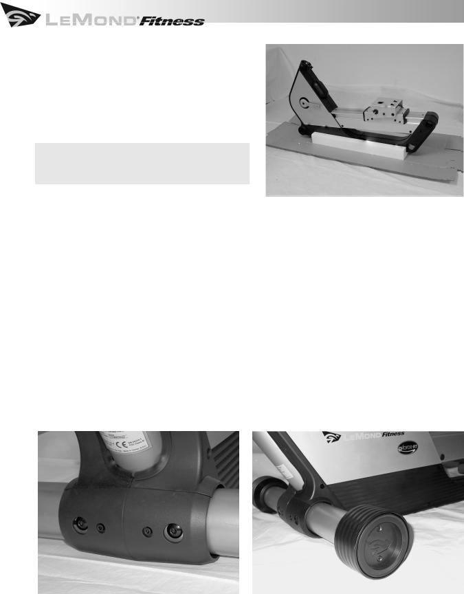
3.5.1 Body
1.Fold down the sides of the carton base and remove the packing material from around the bike.
2.Leave the body of the bike on the carton base while the remaining assembly is completed.
CAUTION: Remove the staples completely to avoid injury.
3.5.2 Front Stabilizer
1.Locate the front stabilizer and the unattached wheel. The front stabilizer already has one wheel attached.
2.Slide the front stabilizer into place at the front of the body frame from the left side. Rotate the stabilizer until the set screw is positioned into the alignment notch. This will align the attachment screw holes of the body and the front stabilizer. Be careful not to dislocate the plastic sleeve at the opposite side of the tubing. If the sleeve is pushed out of place, remove the stabilizer, replace the sleeve and reinstall the stabilizer.
3.Secure the front stabilizer by sliding star washers onto each of (2) M8x30 screws and tightening with the 6mm hex wrench.
4.Slide the remaining front wheel onto the end of the front stabilizer and attach the wheel cap. Use the alignment pins as a guide to install the wheel cap correctly.
5.Secure the wheel cap to the wheel with (2) self-tapping screws and tighten with the 3mm wrench.
12

3 ASSEMBLY AND INSTALLATION INSTRUCTIONS
3.5.3 Rear Stabilizer
1.Locate the rear stabilizer and the leveling feet.
2.Slide the rear stabilizer into place at the rear of the body frame from the right side and rotate until the set screw is positioned in the alignment notch. As with the front stabilizer, be careful not to dislocate the plastic sleeve.
3.Align the holes for the attachment screws on the body and the rear stabilizer. Secure the rear stabilizer by sliding
star washers onto each of (2) M8x30 screws and tighten with the 6mm hex wrench.
4.Attach the leveling foot to the rear stabilizer by screwing it into the underside of the rear stabilizer. Assume at first, that your floors are level and install each foot snugly against the rear stabilizer.
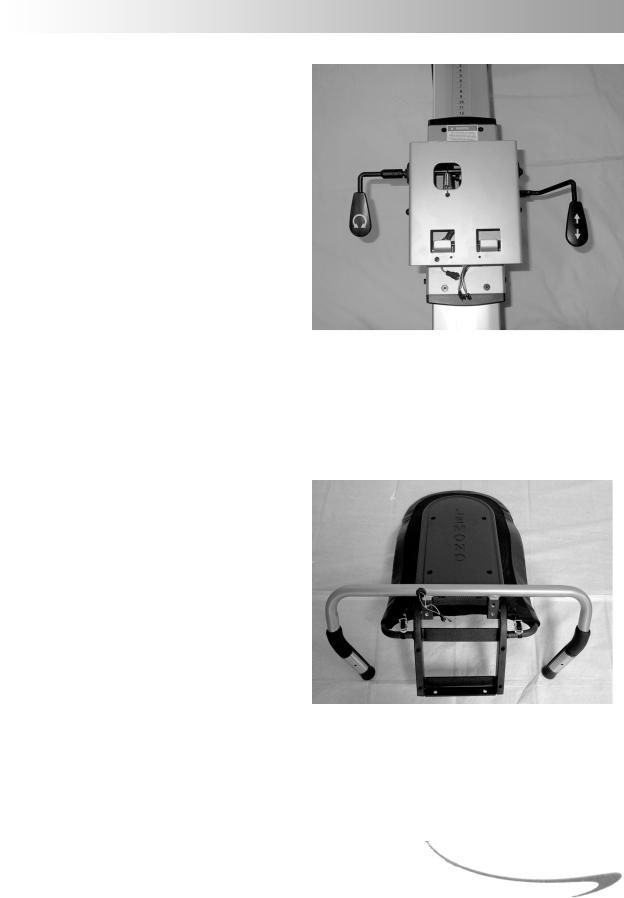
3.5.4 Display Console
Attaching the Console Mast to the Bike
1.Before installing the console mast to the body, locate the (2) wires at the top of the front tube on the body. Feed the wires through the tubing and out of the hole at the top of the console mast.
2.Insert the console mast into the front tubing of the body, taking care to align the holes for the attachment screws of the mast with both the body and the plastic sleeve.
3.Secure the console mast to the body by sliding star washers onto each of (3) M8x20 screws and tighten with the 6mm hex wrench.
13

3 ASSEMBLY AND INSTALLATION INSTRUCTIONS
Attaching the Display Console to the Console Mast
Battery Installation
CAUTION: Never use conventional alkaline batteries. You will damage your electronic parts and void your warranty.
The display console of the g•force RT is powered by (4) rechargeable AA nickel-metal hydride (Ni-MH) batteries, which are included. You provide the power to recharge the batteries by simply pedaling and working out on your bike.
1.Remove the battery compartment cover on the back of the display by pressing down on the tab and then lifting the cover o . An illustration at the bottom of the battery compartment indicates the correct positioning of the batteries.
2.Place the batteries into the compartment as indicated on the illustration. Insert the negative end into position first and then gently push the positive end into place.
3.Replace the battery compartment cover.
Note: Yourbatterieswillnotbefullychargedwhen yourbikearrives.Youwillneedtopedalforatleast1 hourtofullychargethebatteries.
Attaching the Display Console
1.Connect the wires from the console mast to the wires on the back of the display console.
2.Once connected, gently feed the wiring into the console mast until the display console can rest snugly against the platform. The platform of the console mast should fit completely inside the grooved section of the back of the display console.
3.Attach the display console to the console mast using (4) M5x15 screws and tighten with the 3mm hex wrench.
14
3 ASSEMBLY AND INSTALLATION INSTRUCTIONS
3.5.5 Seat
Attaching the Adjustment Handles to the Seat
Carrier
1.Locate the seat adjustment handles. They can be found in the plastic bag containing the tools and other hardware.
2.The shorter, L-shaped handle is attached to the left side of the bike and controls the seat angle adjustment. Slide the handle onto the post on the left side of the seat carrier so that the set screws make contact with the flat portion of the post. Tighten the (2) set screws at the top of the handle with the 2.5 mm hex wrench.
3.The longer handle controls the fore/aft adjustment of the seat and is located on the right side of the bike. Align the (2) holes of the handle with the (2) holes on the right side of the seat carrier. Attach the handle with (2) M5x25 screws and tighten using the 3mm hex wrench.
Attaching the Handlebars to the Seat Assembly
Attach the handlebars to the seat assembly before attaching the seat to the body of the bike.
1.Turn the seat assembly upside down so that the seat rails and the seat back touch the floor.
2.Insert the handlebars into the seat assembly with the holes on the handlebars facing up and aligned with the holes on the seat carrier.
3.Secure the handlebars to the seat assembly by sliding (4) star washers onto each of the (4) M8x20 screws and tighten using the 6mm hex wrench.
15

3 ASSEMBLY AND INSTALLATION INSTRUCTIONS
Attaching the Saddle to the Seat Assembly
1.Place the seat bottom on the rails of the seat assembly.
2.Attach the seat bottom to the seat assembly by sliding (4) star washers onto each of (4) M8x50 screws and tighten using the 6mm hex wrench.
Attaching the Seat Assembly to the Body
Note: Installthehandlebarsandseatbottombefore attachingtheseatassemblytothebodyofthebike.
1.Locate the two tabs that are on the top surface of the seat carrier which is located on the seat track of the body.
2.Located under the seat is a bar that runs the width of the seat. Hook the tabs of the seat carrier over the bar on the seat assembly. (A)
CAUTION: Be careful not to pinch the wiring for the contact heart rate grips when attaching the seat assembly to the seat carrier.
3.Lower the seat assembly over the seat carrier and align the holes at the front of the seat assembly with those on the seat carrier. (B)
4.Secure the seat assembly to the seat carrier by sliding (2) flat washers and (2) star washers onto each of (2) M8x20 screws and tighten with the 6mm hex wrench.
A B
16

3 ASSEMBLY AND INSTALLATION INSTRUCTIONS
Connecting the Wiring for the Contact Heart Rate Grips
Once the seat assembly has been attached to the seat carrier, connect the two wires on the handlebars to their corresponding wires on the seat carrier.
The connection on each of the two wires is di erent.There is only one correct way to make the connection. Do not try to force the connection.
3.5.6 Pedals
Note: Allbicyclepedalshaveadesignated leftandright.Yourpedalsaremarkedas suchonthepedalitself.
Left and right orientation on the bike is
determined as the position you would be in while riding the bike. It is important that you attach each pedal to the corresponding crank, as the threads on the left pedal and crank are reversed. Left pedals are always reverse-threaded so that the pedal tightens rather than loosens while you are pedaling the bike.
CAUTION: Attempting to install the pedals on the incorrect side will cause damage to both the pedal and the crank.
17
 Loading...