

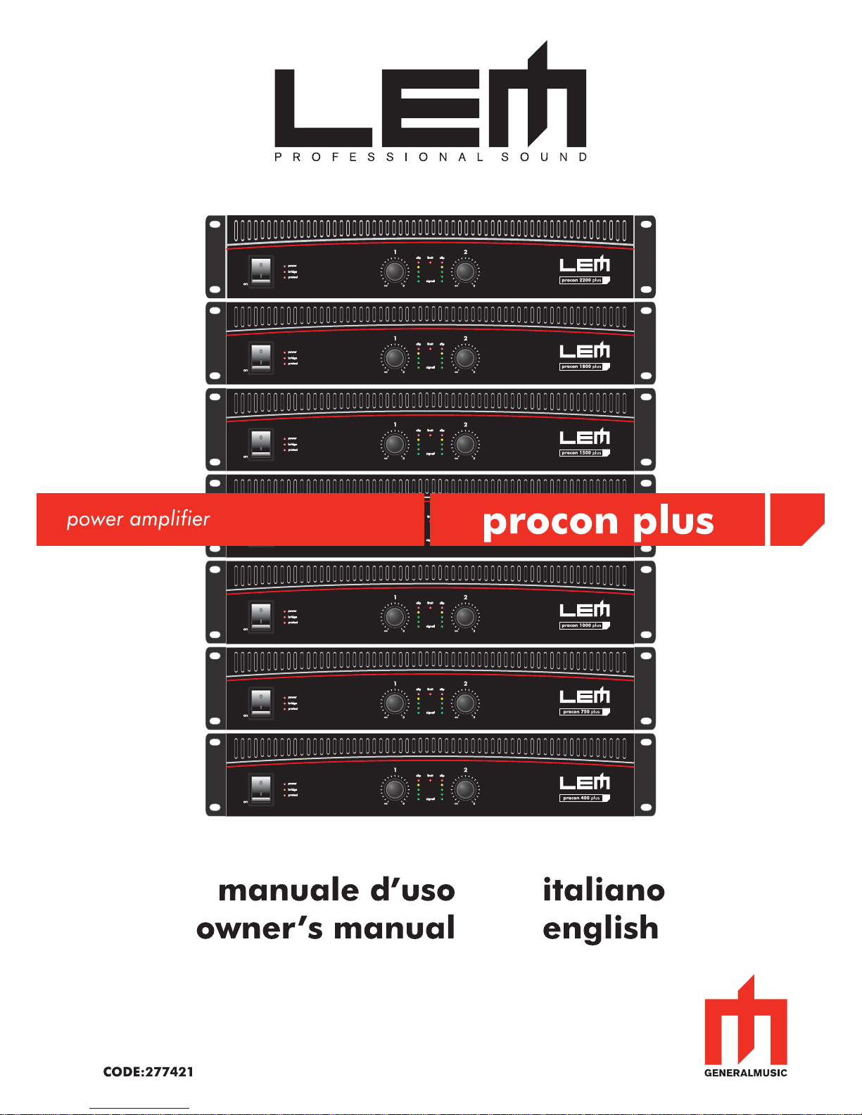
LEM PROCON PLUS 400P, PROCON PLUS 1250P, PROCON PLUS 750P, PROCON PLUS 1000P, PROCON PLUS 1500P Owner's Manual [it, en]
...Page 1
Page 2

IMPORTANT SAFETY INSTRUCTIONS
INSTRUCTIONS PERTAINING TO A RISK OF FIRE, ELECTRIC SHOCK OR INJURY TO PERSONS
WARNING - When using electric products, basic precautions should always be followed, including the
following:
1. Read all the SAFETY INSTRUCTIONS before using the product.
2. To reduce the risk of injury, close supervision is necessary when the product is used near children.
3. Do not use this product near water - for example, near a bathtub, washbowl, kitchen sink, in a wet
basement or near a swimming poor or the like.
4. This product in combination with headphones or an amplifi er, may be capable of producing sound
levels that could cause permanent hearing loss. Do not operate for a long period of time at high volume
level or at a level that is uncomfortable. If you experience any hearing loss or ringing in the ears, you
should consult an audiologist.
5. This product should be located so that its location or position does not interfere with its proper
ventilation.
6. This product should be located away from heat sources such as radiators, heat registers or other
products that produce heat.
7. The product should be connected to a power supply only of the type described on the operating
instructions or as marked on the product.
8. This product may be equipped with a polarized line plug (one blade wider than the other). This is a
safety feature. If you are unable to insert the plug into the outlet, contact an electrician to replace your
obsolete outlet. Do not defeat the safety purpose of the plug.
9. The power-supply cord of the product should be unplugged from the outlet when left unused for a
long period of time. When unplugging the power-supply cord, do not pull on the cord, but grasp it by
the plug.
10. Care should be taken so that object do not fall and liquid are not spilled into the enclosure through
openings.
11. The product should be serviced by qualifi ed service personnel when:
A. The power-supply cord or the plug has been damaged; or
B. Objects have fallen, or liquid has been spilled into the product; or
C. The product has been exposed to rain; or
D. The product does not appear to operate normally or exhibits a marked change in performance; or
E. The product has been dropped or the enclosure damaged.
12. Do not attempt to service the product beyond that described in the user-maintenance instructions.
All other servicing should be referred to qualifi ed service personnel.
13. WARNING - Do not place objects on the product's power cord or place it in a position where anyone
could trip over, walk on or roll anything over it. Do not allow the product to rest on or to be installed over
power cords of any type. Improper installations of this type create the possibility of fi re hazard and/or
personal injury.
SAVE THESE INSTRUCTIONS
The lightning flash with arrowhead symbol within an
equilateral triangle is intended to alert the user to the
presence of uninsulated "dangerous voltage" within the
product's enclosure, that may be of sufficient magnitude to
constitute a risk of electric shock to persons.
The exclamation point within an equilateral triangle is
intended to alert the user to the presence of important
operating and maintenance (servicing) instructions in the
literature accompanying the appliance.
Page 3

procon plus
3
1. Introduzione
Congratulazioni per l’acquisto degli amplificatori
procon plus! Per un impiego corretto seguite le
istruzioni riportate in questo manuale. Buon divertimento
e buon lavoro.
2. Sommario
3. Norme di Installazione ed Uso . . . . . . . . . . .3
4. Funzioni e Controlli . . . . . . . . . . . . . . . . . . .4
6. Pannello Connessioni . . . . . . . . . . . . . . . . .4
7. Specifi che Tecniche . . . . . . . . . . . . . . . . . . .5
3. Norme di Installazione ed Uso
ATTENZIONE !!!
Gli amplificatori della serie PROCON PLUS
producono un elevato voltaggio in uscita. Per
evitare rischi di shock elettrico NON TOCCATE
alcun fi lo scoperto mentre l’apparato è acceso.
1. Collegamento alla rete
Prima di collegare l’amplifi catore alla presa della corrente
accertatevi sempre che:
- l’impianto elettrico e la presa della corrente dispongano
di un’appropriata messa a terra compatibile con le
norme di sicurezza (in caso di incertezza consultate
personale specializzato);
- la tensione di rete corrisponda a quella indicata sul retro
dell’apparato (è accettata una tolleranza fi no a ±10%);
- il cavo di alimentazione non sia danneggiato e non
presenti fi li scoperti;
- il pulsante di accensione sia in posizione OFF .
Assicuratevi che l’amplifi catore sia spento anche prima
di scollegare il cavo di alimentazione dalla presa della
corrente.
2. Accensione e spegnimento
Nel vostro impianto di amplificazione accendete
l’amplifi catore sempre per ultimo e spegnetelo sempre
per primo: eviterete fastidiosi e talvolta pericolosi picchi
di segnale. E’ normale che all’accensione i vari LEDs
del pannello frontale rimangano illuminati per alcuni
istanti).
3 Installazione e uso
Il vostro amplificatore PROCON PLUS genera una
potenza decisamente elevata. Installatelo, pertanto, in
collocazioni che consentano una corretta circolazione
d’aria. Evitate prolungate esposizioni alla irradiazione
solare diretta, a forti fonti di calore, ad intense
vibrazioni, ad ambienti molto polverosi o particolarmente
umidi o, peggio ancora, alla pioggia: eviterete possibili
malfunzionamenti, deterioramenti o addirittura shock
elettrici ed incendi.
L’aria per il raffreddamento dell’apparato viene forzata
ad entrare attraverso le feritoie del pannello frontale e
ad uscire da quelle del pannello posteriore. Assicuratevi,
pertanto, che attorno all’amplificatore vi sia spazio
suffi ciente per consentire un adeguato riciclo d’aria.
Se utilizzate rack o flight-cases, assicuratevi che
l’aria possa defl uire senza resistenza: non installate
gli amplificatori in rack o flight-cases con la parte
posteriore chiusa.
4. Collegamenti audio
Ricordate di effettuare e rimuovere i collegamenti con
altri apparati sempre ad amplifi catore spento.
Per il collegamento tra uscite del mixer ed ingressi
degli amplificatori utilizzate di preferenza “cavi
segnale bilanciati”: l’utilizzo di cavi sbilanciati potrebbe
facilmente determinare l’insorgere di fastidiosi ronzii e
rumori di fondo. Per il collegamento tra uscite di potenza
degli amplifi catori e casse acustiche utilizzate sempre e
solo “cavi potenza” (cavi per casse acustiche costituiti
da due fi li di grossa sezione). Abbiate cura dei cavi
di collegamento, afferrandoli sempre per i connettori,
evitando di tirarli lungo il cordone ed avvolgendoli
senza nodi o forti torsioni: ne allungherete la vita e
l’affi dabilità, a vostro assoluto vantaggio. Verifi cate
periodicamente che i cavi che impiegate siano in buono
stato, con le connessioni realizzate nel modo corretto e
con tutti i contatti in perfetta effi cienza: spesso, infatti,
molti problemi ed inconvenienti (falsi contatti, rumori
di massa, scariche, ecc.) sono dovuti unicamente
all’utilizzo di cavi inadatti o avariati.
5. Prevenzione o individuazione di disturbi
Verifi cate, innanzitutto, che il luogo di installazione non
presenti disturbi industriali o a radio frequenza. Evitate
comunque di installare la vostra apparecchiatura in
stretta prossimità di apparecchi radio, TV, telefoni
cellulari, etc., in quanto questi potrebbero causare
interferenze rumorose. Collegando gli apparati del
vostro impianto audio, fate attenzione ai cosiddetti
“loop di massa” che potrebbero causare ronzii: in caso
di disturbi, provate ad agire sullo switch SHIELD posto
sul pannello connessioni dell'amplifi catore.
6. Protezione e manutenzione
L’amplificatore è realizzato in materiale antiurto, in
ogni caso è buona norma proteggerne il trasporto con
fl ight-case, imballaggi o contenitori simili per prevenirne
gli incidenti del caso. Dopo un uso prolungato,
specialmente in ambienti polverosi, l’accumulo
interno di polvere può interferire con il raffreddamento
dell’apparato. Senza aprire l’amplificatore ed
assicurandovi di averlo scollegato dalla presa della
corrente, potete rimuovere la polvere usando dell’aria
compressa, forzandola attraverso le feritoie dello
chassis. Se l’accumulo risulta eccessivo, non aprite
Page 4

4
procon plus
l’amplifi catore, poiché potreste esporvi a seri rischi
di shock elettrici: rivolgetevi al più vicino Centro di
Assistenza GENERALMUSIC.
7. In caso di avaria
Tutte le regolazioni sono esterne ed accessibili alla
vostra portata. Non aprite mai l’amplifi catore: potreste
esporvi a seri rischi di shock elettrici. In caso di
avaria rivolgetevi al più vicino Centro di Assistenza
GENERALMUSIC.
4. Funzioni e controlli (fi g. 1)
1. POWER ON/OFF
Interruttore di accensione e spegnimento.
2. POWER ON LED
LED di segnalazione dell’accensione dell’apparato.
3. BRIDGE LED
LED di segnalazione dell’attivazione della modalità
BRIDGE (vedi MODE in Pannello Connessioni).
4. PROTECT LED
Indicatore di intervento delle protezioni.
Segnala l'attivazione di una delle protezioni che
salvaguardano le diverse sezioni dell'amplifi catore in
caso di condizione anomala di funzionamento. In questi
casi, l'erogazione della potenza viene sospesa fi no al
ripristino delle normali condizioni di funzionamento.
5. ATTENUATORI d’INGRESSO
Potenziometri a 21 scatti per l’attenuazione del
guadagno d'ingresso. Consentono di attenuare il
livello del segnale esterno verso i rispettivi canali
dell’amplifi catore. La regolazione avviene per valori
continui espressi in dB e compresi tra:
∞
: tutto chiuso (il segnale viene completamente
attenuato e, quindi, non viene inviato al canale
dell’amplifi catore);
0 : tutto aperto ovvero livello nominale (il segnale
non subisce alcuna attenuazione e, quindi,
viene inviato al canale dell’amplifi catore con lo
stesso livello con il quale giunge in ingresso).
6. METERS
BARGRAPHS a 5 LED per la visualizzazione del
livello del segnale. I LED sono di 3 diversi colori.
• verde: indicano condizioni operative normali.
• giallo: si accendono a -6dB rispetto al livello
massimo.
• rosso: segnalano il “clipping” degli stadi di
amplifi cazione, vale a dire la condizione in cui
il livello del segnale audio eccede la capacità
d’uscita del canale dell’amplifi catore. Quando
questi LEDs si accendono, riducete il livello
del segnale in ingresso nell’amplifi catore.
7. LIMIT LED
Indicatore di intervento del circuito di CLIP LIMITER.
L'accensione di questo LED indica che il circuito di CLIP
LIMITER riconosce segnali in ingresso di livello troppo
elevato e, di conseguenza, attiva il LIMITER in modo da
evitare distorsioni dell'amplifi catore.
5. Pannello Connessioni (fi g. 2)
1. INPUTS
Connettori XLR-F bilanciati (0 dB).
Sono gli ingressi dei due canali dell’amplificatore.
Possono ricevere segnali di linea ad alta impedenza
bilanciati o sbilanciati, provenienti da apparecchiature
con uscita ad alto livello.
NOTA: Usate possibilmente cavi bilanciati. In ogni caso, evitate di
usare un cavo bilanciato per un canale e uno sbilanciato per l’altro
poiché otterreste una sensibile differenza di livello tra un canale
e l’altro.
2. LINK
Connettori JACK bilanciati (0 dB).
Questi connettori sono collegati in “parallelo” con i
rispettivi connettori XLR-F. Ciò consente di rilanciare
il segnale verso un secondo apparato (ad esempio,
un’altro amplificatore). In questo modo è possibile
pilotare più amplifi catori utilizzando lo stesso segnale,
realizzando, così, sistemi di amplifi cazione di maggiore
portata.
3. OUTPUTS
Connettori per il collegamento dei diffusori.
Nei modelli 400P, 750P, 1000P, 1250P e 1500P per
ciascun canale sono presenti un connettore SPEAKON
e due connettori BINDING POST collegati nel seguente
modo:
- PIN 1+ collegato in parallelo al BINDING POST “+”
(colore rosso);
- PIN 1- collegato in parallelo al BINDING POST “-”
(colore nero);
- PIN 2+ e 2- NON collegati.
L'uscita BRIDGE è costituita dai due connettori
BINDING POST positivi (colore rosso), la cui polarità è
indicata in serigrafi a.
Nei modelli 1800P e 2200P è presente un conettore
SPEAKON per ciascun canale più un ulteriore
connettore SPEAKON dedicato per l'uscita BRIDGE.
NOTA: per evitare possibili danni alle casse acustiche, collegate
solo diffusori o sistemi di diffusori compatibili con i limiti di carico
di potenza e di impedenza dichiarati dall’amplifi catore (in tal senso
consultate il capitolo “Specifi che Tecniche” per avere riferimenti
sul vostro modello di amplifi catore). Usate solo cavi per casse
acustiche e mai cavi segnale ovvero cavi utilizzati normalmente per
microfoni, strumenti e apparecchiature audio in genere.
Page 5
procon plus
5
4. MODE
Selettore delle due modalità di funzionamento
dell'amplifi catore.
a) STEREO: in questa modalità, 2 segnali separati
vengono trattati separatamente dai canali 1 e 2
dell'amplifi catore ed inviati rispettivamente alle uscite
1 e 2.
b) BRIDGE: in questa modalità, 1 solo segnale
collegato all'ingresso 1 viene amplifi cato dalle sezioni
1 e 2 dell'amplifi catore sommate tra loro ed inviato
all'uscita BRIDGE con potenza ed impedenza nominali
raddoppiate (vedi Specifi che Tecniche).
Nei modelli 400P, 750P, 1000P, 1250P e 1500P,
l'uscita BRIDGE è costituita dai due connettori BINDING
POST positivi (colore rosso), la cui polarità è indicata
in serigrafi a.
Nei modelli 1800P e 2200P l'uscita BRIDGE presenta
un proprio connettore SPEAKON dedicato.
Nella sezione CONNECTION EXAMPLES potete trovare
gli schemi di connessione per entrambe le modalità.
5. SHIELD
Controllo di separazione della massa elettrica dalla
massa del telaio. Agite su questo selettore nel caso si
verifi chino ronzii dovuto ai cosiddetti “loop di massa”.
6. A.C. ~
Cavo di alimentazione.
7. Alloggiamento fusibile principale
In caso di rottura del fusibile, sostituitelo sempre con
uno dello stesso tipo e dello stesso valore.
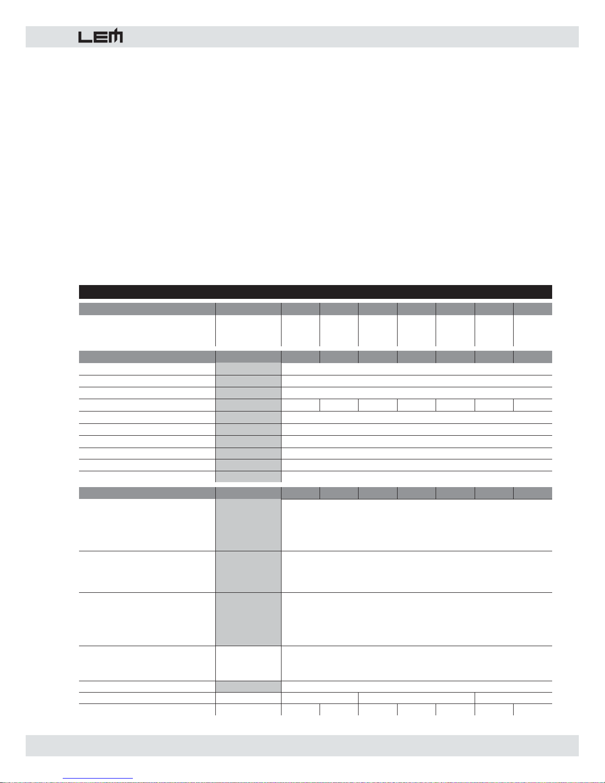
SPECIFICHE DI POTENZA
400P 750P 1000P 1250P 1500P 1800P 2200P
Potenza di uscita EIA
1kHz, THD massima 1%
Entrambi i canali
8 ohm
4 ohm
8 ohm BRIDGED
125+125
200+200
400
215+215
375+375
750
300+300
550+550
1100
375+375
625+625
1250
450+450
750+750
1500
550+550
900+900
1800
650+650
1100+1100
2200
SPECIFICHE ELETTRONICHE
400P 750P 1000P 1250P 1500P 1800P 2200P
SENSIBILITA' DI INGRESSO
IMPEDENZA DI INGRESSO
RISPOSTA in FREQUENZA
GUADAGNO in VOLTAGGIO
32dB 33dB 35dB 36dB 37dB 37dB 39dB
SLEW RATE
DAMPING FACTOR
DIAFONIA
Rapporto S/N
Distorsione armonica (THD+N)
Distorsione di intermodulazione SMPTE
SPECIFICHE GENERALI
400P 750P 1000P 1250P 1500P 1800P 2200P
PROTEZIONI
CONTROLLI
INDICATORI
CONNETTORI
IN
OUT
ALIMENTAZIONE
DIMENSIONI
mm (LxAxD)
PESO
kg 13 15 18 19.5 21 23.5 25
PROCON PLUS SERIES • SPECIFICHE TECNICHE
0dB (0.775V)
10 kOhms (bilanciato)
10÷50000 Hz (-0.5dB)
22 V/ms
>400:1 @ 1kHz, 8Ohms
-82 dB (1KHz)
Protezione termica sul trasformatore
Protezione contro il corto circuito
Rilevatore di corrente in uscita
CLIP Limiter su ciascun canale
Circuito soft start (dal 1000P al 2200P)
-100 dB
483x88x456
<0.1% (ref 20Hz -20KHz)
<0.1% (metodo SMPTE, 60Hz & 7kHz, rapporto 4:1)
1 XLR-F + 1 JACK in parallelo per ciascun canale
2 x BINDING POST + 1 SPEAKON per ciascun canale (400-1500)
1 SPEAKON per ciascun canale + 1 SPEAKON per uscita BRIDGE (1800-2200)
483x88x366 483x88x428
Interruttore di accensione
Controllo di livello per ciascun canale a 21 scatti
Selettore MODE
Selettore SHIELD
POWER ON: 1 LED rosso
BRIDGE: 1 LED rosso
PROTECT: 1 LED rosso
LEVEL: 2 barre a 5 LEDs
LIMIT: 1 LED rosso
vedi etichetta sull'apparato
Page 6

6
procon plus
1. Introduction
Congratulations for having chosen a procon plus
power amplifi er! To make the best use of your amplifi er,
please read this manual thoroughly before operating
the equipment.
2. Contents
3. Instructions for use and installation . . . . . . .6
4. Functions & Controls . . . . . . . . . . . . . . . . . .7
5. Connection Panel . . . . . . . . . . . . . . . . . . . .7
9. Technical Specifi cations . . . . . . . . . . . . . . .8
3. Instructions for use and installation
ATTENTION !!!
The PROCON PLUS series amplifiers generate
high voltage on output. To avoid the risk of electric
shocks, DO NOT TOUCH any bare wires when the
unit is switched on.
1. Connection to the mains supply
Before connecting the amplifi er to the mains socket,
always make certain that:
- the electric system and mains socket have an
adequate grounding, compatible with the safety norms
(if you’re uncertain, consult specialized personnel);
- the mains voltage corresponds to that shown on
the rear of the unit (an allowance of up to ±10% is
accepted);
- the power cord is not damaged and has no bare
wires;
- the on/off switch is in the OFF position.
Make sure the amplifi er is also off before disconnecting
the power cord from the mains socket.
2. Switching on and off
In your sound reinforcement system, always switch on
the amplifi er after all the other equipment and always
switch it off before anything else, if possible with the
Gain controls set at minimum: this will avoid annoying
and sometimes dangerous signal peaks.
3 Installation and use
Your PROCON PLUS amplifi er generates decidedly
high power, so install it in locations which ensure correct
air circulation. Avoid long exposure to direct sunlight,
sources of strong heat, powerful vibrations, very dusty
or particularly damp surroundings or (even worse) rain:
this will avoid possible faulty operation, deterioration or
even electric shocks and fi res.
The air for cooling the unit is forced in through the
vents in the front panel and out through those on the
rear panel, so make certain that there’s suffi cient space
round the amplifi er to allow adequate air circulation.
If racks or fl ight-cases are used, make sure that airfl ow
is unobstructed: don’t install the amplifi ers in racks or
fl ight-cases with closed backs. Since part of the heat
is dissipated thru the metal bottom of the amplifi er, it’s
advisable to install the amplifi ers with at least one rack
unit space between them.
4. Audio connections
Remember to always connect and disconnect other
units with the amplifi er switched off.
To connect the mixer outputs to the amplifi ers inputs,
make certain to always use balanced signal cables: the
use of unbalanced cables could in fact probably cause
annoying hum and noise. To connect the amplifi er to
the loudspeaker enclosures always use power cables
(speaker cables made up of two wires, normally with
a large cross-section). Take care of your connector
cables, always gripping them by the plugs, avoid pulling
them directly and winding them without knots or bends:
they’ll last longer and be more reliable, which is to your
advantage. Check periodically that your cables are
in good condition, correctly wired and with perfectly
effi cient contacts: in fact many problems and drawbacks
(false contacts, ground hum, crackles, etc.) are caused
by the use of unsuitable or damaged cables.
5. Preventing or identifying interference
First of all, check that the amplifi er is installed in a place
free from industrial or RF (radio frequency) interference.
Avoid installing your equipment very near radio or TV
sets, mobile phones, etc., as these can cause noisy
interference. When connecting the other components of
your sound system, watch out for the so-called “ground
loops”, which could cause hum and jeopardize the
amplifi er’s excellent Signal-to-Noise and low distortion
characteristics. In case hum noises would occur, try the
SHIELD switch on the amplifi er's rear panel.
6. Protection and maintenance
The amplifier is built in shock-resistant material.
Nevertheless, protect it during transport with a fl ightcase to avoid the risk of any casual accidents.
After long periods of use, particularly in dusty
surroundings, accumulated dust may interfere with the
unit’s cooling. Without opening the amplifi er and making
certain it’s disconnected from the mains supply, dust
can be removed with a jet of compressed air, forcing it
out through the chassis’ louvers. If the dust build-up is
excessive, don’t open the amplifi er, as you could run
the risk of serious electric shocks: contact the nearest
GENERALMUSIC Assistance Centre
7. In the event of breakdown
All user-adjustable parts are external and easily
accessible. Never open the amplifi er: you could run the
risk of serious electric shocks.
Page 7

procon plus
7
NB: Whenever possible, use balanced cables. In any case, avoid
using a balanced cable for one channel and an unbalanced one
for the other, as this would cause a considerable difference in
channel levels.
2. LINK
Balanced JACK connectors (0 dB).
These connectors are connected in parallel with the
respective XLR-F connectors. This enables a second
unit (e.g. another amplifi er) to be daisy-chained to the
fi rst. It’s thus possible to feed several amplifi ers using
the same signal.
3. OUTPUTS
Power connectors.
In the 400P, 750P, 1000P, 1250P and 1500P models
each channel has 1 SPEAKON and 2 BINDING POST
connectors wired in this way:
- PIN 1+ connected in parallel to the “+” BINDING POST
“+” (red color);
- PIN 1- connected in parallel to the “-” BINDING POST
“+” (black color);
- PIN 2+ and 2- NOT connected.
The BRIDGE output is made up of the two positive
BINDING POST connectors (red color) and its polarity
is printed on the amplifi er's panel.
In the 1800P and 1500P models each channel has just
1 SPEAKON and the BRIDGE output is made up of
another dedicated SPEAKON connector.
NOTE: to avoid possible damage to the loudspeaker enclosures,
only connect enclosures or speaker systems compatible with
the power load and impedance limits indicated for the amplifi er
(regarding this, consult the “Technical specifi cations” chapter for
reference to your specifi c amplifi er model). Use only loudspeaker
enclosure cables, never signal cables, i.e. those normally used for
microphones, instruments and audio equipment in general.
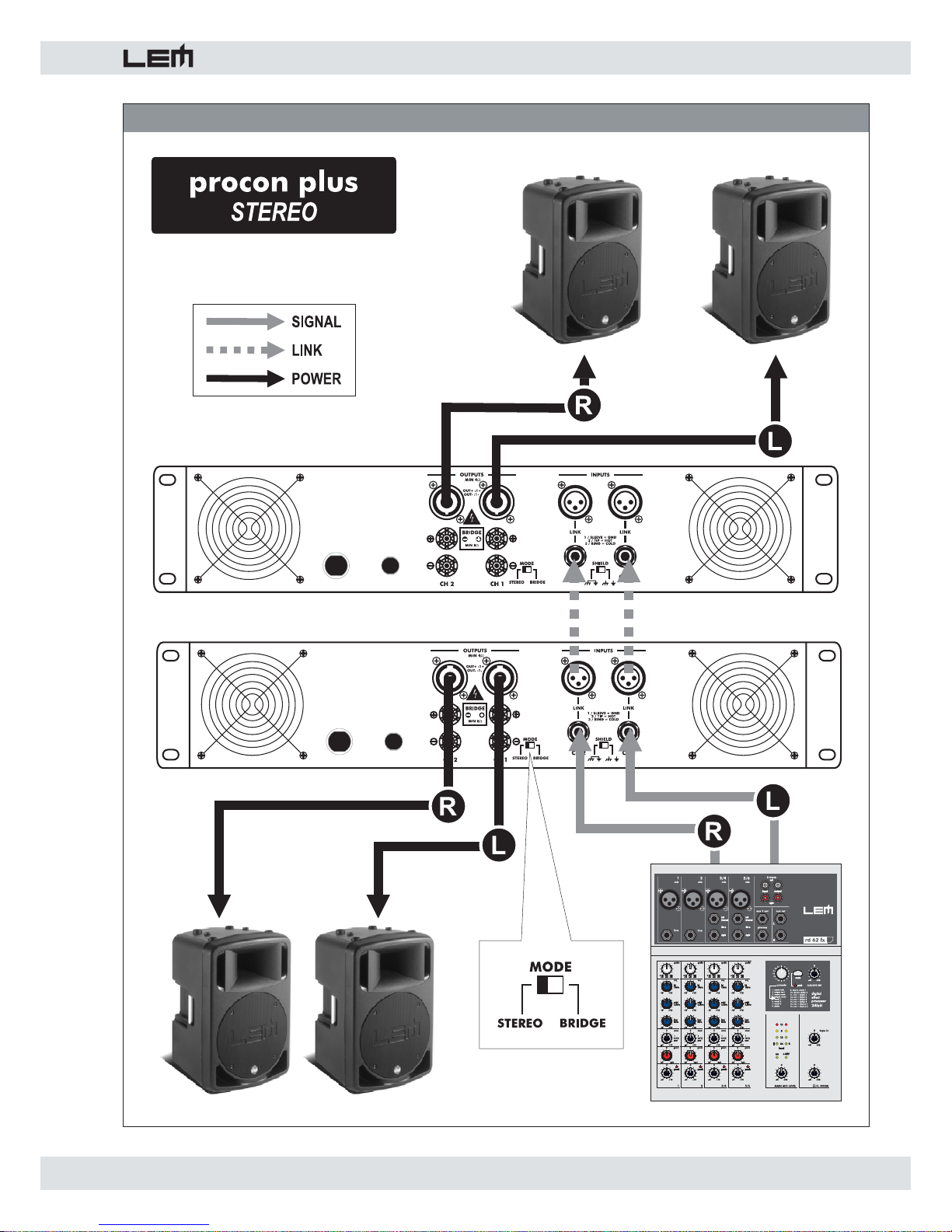
4. MODE
Selector for the amplifi er's two operating modes.
a) STEREO: in this operating mode 2 separate signals
are treated separately by channels 1 and 2 of the
amplifi er and sent respectively to outputs 1 and 2.
b) BRIDGE: in this operating mode 1 single signal
connected to the input 1 is amplifi ed by the two sections
of the amplifier summed together and sent to the
BRIDGE output with double the power and rated
impedance (see Technical Specifi cations).
In the 400P, 750P, 1000P, 1250P and 1500P models
the BRIDGE output is made up of the two positive
BINDING POST connectors (red color) and its polarity
is printed on the amplifi er's panel.
In the 1800P and 1500P models the BRIDGE output
has its own dedicated SPEAKON connector.
In the event of breakdown, contact the nearest
GENERALMUSIC Assistance Centre.
4. Functions & Controls (fi g. 1)
1. POWER ON/OFF
ON/OFF switch.
2. POWER ON LED
LED indicating when the amplifi er is switched on.
3. BRIDGE LED
LED indicating when the BRIDGE mode is activated
(see MODE in Connection Panel).
4. INPUT ATTENUATORS
Input gain attenuator potentiometers.
Attenuate the level of the external signal sent to the
respective channels of the amplifi er.
Continuously variable values, expressed in dB, are
between:
∞
: fully closed (the signal is completely attenuated
and therefore not sent to the channel of the
amplifi er);
0 : fully open, i.e. nominal level (the signal is not
attenuated in any way, so is fed to the amplifi er
channel at the same level at which it arrives on
input).
5. METERS
5-LED bargraphs for the visualization of the input
signal. The LEDs are of three different colors:
• green: show the normal operative level of the
signal;
• yellow: light up at -6dB referred to the maximum
level;
• red (CLIP): indicate clipping (the audio signal level
exceeds the output capacity of the
amplifi er channel). When these LEDs
fl ash reduce the input signal level.
6. LIMIT LED
CLIP LIMITER indicator.
Indicates that the CLIP LIMITER circuit has sensed a
too high input signal and has therefore activated the
LIMITER in order to avoid excessive distortions.
5. Connection Panel (fi g. 2)
1. INPUTS
Balanced XLR-F connectors (0 dB).
The inputs of the amplifi er’s two channels. Can receive
balanced or unbalanced high impedance line signals
from equipment with high level outputs.
Page 8
8
procon plus
You can fi nd schematic drawings for each operating
mode in the CONNECTION EXAMPLES section.
5. SHIELD
Control for separating the electrical earth from that
of the chassis. Use this control to try to eliminate hum
noises due to so-called 'ground loops'.
6. A.C. ~
Power cord.
7. Main fuse holder
In the event of breaking, always replace the fuse with
same type and rating.
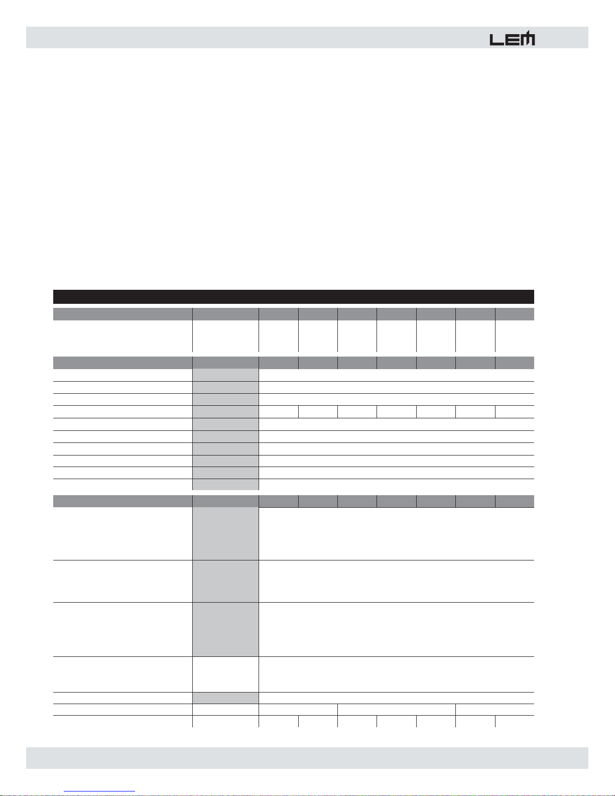
POWER SPECIFICATIONS
400P 750P 1000P 1250P 1500P 1800P 2200P
EIA output power
1kHz, THD maximum 1%
Both channels
8 ohm
4 ohm
8 ohm BRIDGED
125+125
200+200
400
215+215
375+375
750
300+300
550+550
1100
375+375
625+625
1250
450+450
750+750
1500
550+550
900+900
1800
650+650
1100+1100
2200
ELECTRICAL SPECIFICATIONS
400P 750P 1000P 1250P 1500P 1800P 2200P
INPUT SENSITIVITY
INPUT IMPEDANCE
FREQUENCY RESPONSE
VOLTAGE GAIN
32dB 33dB 35dB 36dB 37dB 37dB 39dB
SLEW RATE
DAMPING FACTOR
CROSSTALK
S/N ratio
Harmonic distortion THD
Intermodulation distortion SMPTE
GENERAL SPECIFICATIONS
400P 750P 1000P 1250P 1500P 1800P 2200P
PROTECTIONS
CONTROLS
INDICATORS
CONNECTORS
IN
OUT
POWER SUPPLY
DIMENSIONS
mm (WxHxD)
WEIGHT
kg 13 15 18 19.5 21 23.5 25
483x88x456
<0.1% (ref 20Hz -20KHz)
<0.1% (SMPTE method, 60Hz & 7kHz, 4:1 ratio)
1 XLR-F + 1 JACK in parallel for each channel
2 x BINDING POST + 1 SPEAKON for each channel (400-1500)
1 SPEAKON for each channel + 1 SPEAKON for BRIDGE output (1800-2200)
483x88x366 483x88x428
ON/OFF switch
21-detect input level control for each channel
MODE selector
SHIELD selector
POWER ON: 1 red LED
BRIDGE: 1 red LED
PROTECT: 1 red LED
LEVEL: 2 x 5-LED meters
LIMIT: 1 red LED
see label on the unit
22 V/ms
>400:1 @ 1kHz, 8Ohms
-82 dB (1KHz)
Power transformer thermal protection
Short circuit protection
Sensor for current on outputs
CLIP Limiter on each channel
Soft-start circuit (1000P to 2200P)
-100 dB
PROCON PLUS SERIES • TECHNICAL SPECIFICATIONS
0dB (0.775V)
10 kOhms (balanced)
10÷50000 Hz (-0.5dB)
Page 9

procon plus
9
FIG. 2 - PANNELLO CONNESSIONI - CONNECTION PANEL
FIG. 1 - PANNELLO FRONTALE - FRONT PANEL
FIG. 3 - CAVI DI COLLEGAMENTO - CONNECTION CABLES
XLR-M bilanciato / Balanced XLR-M JACK bilanciato / Balanced JACK
Connettore di potenza SPEAKON / SPEAKON power connector
Page 10
procon plus
10
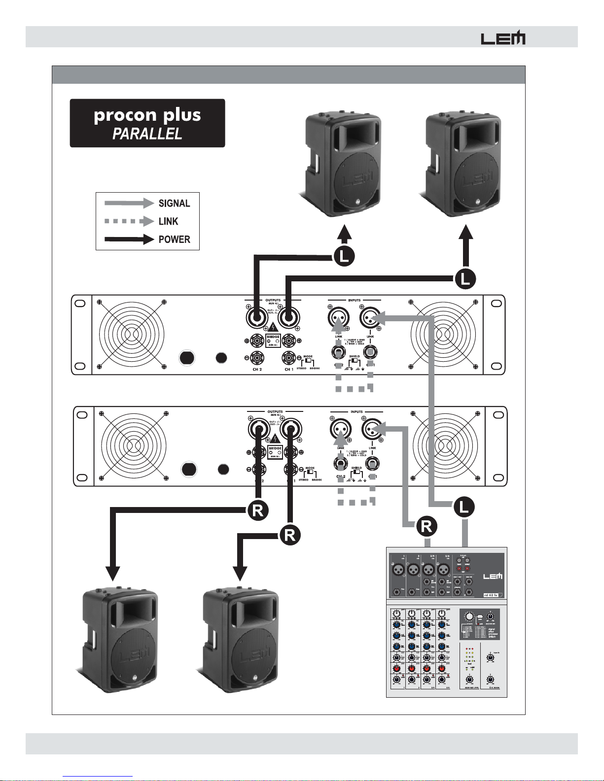
FIG. 4 - ESEMPI DI COLLEGAMENTO - CONNECTION EXAMPLES
Page 11
11
procon plus
FIG. 5 -ESEMPI DI COLLEGAMENTO - CONNECTION EXAMPLES
Page 12

procon plus
12
FIG. 6 - ESEMPI DI COLLEGAMENTO - CONNECTION EXAMPLES
Page 13

Le informazioni contenute in questo documento sono state at ten ta men te redatte e controllate. Tuttavia non è assunta
alcuna re spon sa bi li tà per eventuali inesattezze.
Tutti i diritti sono riservati e questo documento non può essere copiato, fotocopiato, riprodotto per intero o in parte
senza previo consenso scritto della GENERALMUSIC S.p.A.
GENERALMUSIC si riserva il diritto di apportare senza preavviso cam bia men ti e modifi che estetiche, funzionali o
di design a ciascun proprio prodotto.
GENERALMUSIC non assume alcuna responsabilità sull’uso o sul l’ap pli ca zio ne dei prodotti o dei circuiti qui
descritti.
STAMPATO IN P.R.C.
The information contained in this publication has been carefully prepared and checked. However no responsibility
will be taken for any errors.
All rights are reserved and this document cannot be copied, photocopied or reproduced in part or completely without
written consent being obtained in advance from GENERALMUSIC S.p.A.
GENERALMUSIC reserves the right to make any aesthetic, functional or design modifi cation to any of its products
without any prior notice.
GENERALMUSIC assumes no responsibility for the use or application of the products or circuits described
herein.
PRINTED IN P.R.C.
Page 14

 Loading...