

Page 1

Page 2

spn series
1. Introduzione
Congratulazioni per l’acquisto dei diffusori spn series!
Per un impiego corretto seguite le istruzioni riportate in
questo manuale. Buon divertimento e buon lavoro!
2. Sommario
3. Norme di Installazione ed Uso . . . . . . 2
1. La protezione e la manutenzione. . . . . . . . .2
2. Prevenzione di possibili disturbi. . . . . . . . .2
3. Collegamenti . . . . . . . . . . . . . . . . . . . . . . 2
4. I cavi di collegamento . . . . . . . . . . . . . . . .2
4. La serie spn . . . . . . . . . . . . . . . . . . . 2
5. Installazione . . . . . . . . . . . . . . . . . . . 2
6. Pannello connessioni spn6a/spn8a . . . 3
7. Pannello connessioni spn12sa . . . . . . 3
8. Sistemi spn . . . . . . . . . . . . . . . . . . . 4
9. Specifiche Tecniche . . . . . . . . . . . . . . 4
3. Norme di Installazione ed Uso
1. La protezione e la manutenzione.
Evitate di collocare i diffusori in vicinanza di forti fonti di
calore e di esporli direttamente alla luce solare, alla pioggia,
all’umidità, alla polvere o ad intense vibrazioni. Lasciate
l’apposita griglia di protezione sempre applicata ai diffusori.
In caso di avaria non aprite il diffusore, ma rivolgetevi al più
vicino Centro di Assistenza GENERALMUSIC.
2. Prevenzione di possibili disturbi.
Collegando gli apparati del vostro impianto audio, fate
attenzione ai cosiddetti “loop di massa” che potrebbero
causare ronzii: in caso di disturbi, provate ad agire sullo
switch SHIELD posto sul pannello controlli del diffusore.
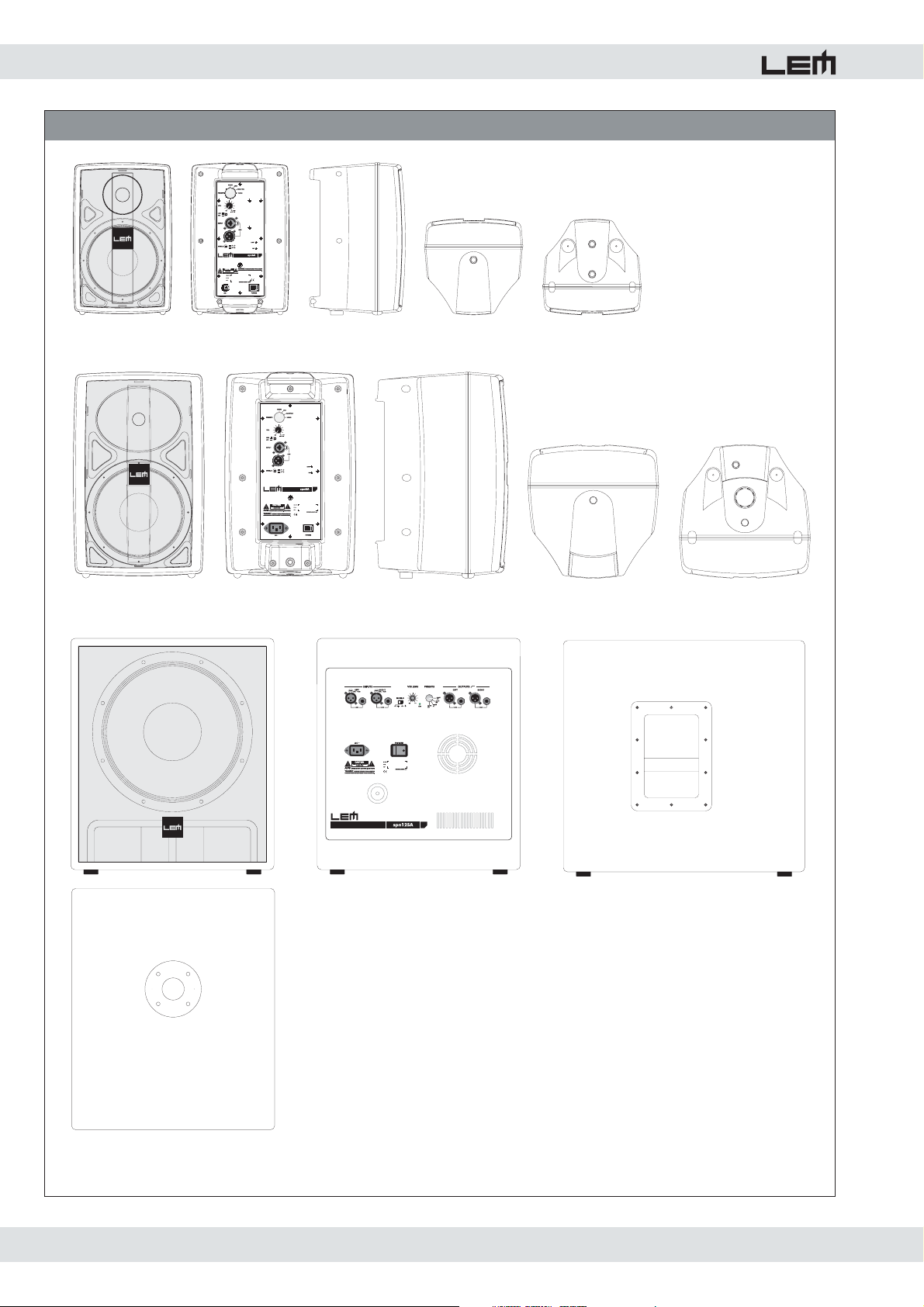
4. La serie spn (fig. 1)
La serie spn è una linea di diffusori amplificati compatti
con cabinet in polipropilene (spn6a e spn8a) o multistrato
(spn12sa), progettati per l'impiego in installazioni fisse,
sistemi multimediali o sistemi di amplificazione portatili di
piccole dimensioni. La serie si compone di 3 modelli.
- spn6a: utilizza un driver a compressione al neodimio da
1” su guida d'onda sferica ed un woofer da 6.5” sempre
al neodimio con schermatura magnetica. Il modulo di
amplificazione incorporato include un amplificatore da 130W
con tecnologia PWM per la sezione bassi ed un amplificatore
in classe AB da 20W per la sezione alti.
- spn8a: utilizza un driver a compressione da 1” su tromba
EWT ed un woofer da 8” al neodimio. La potenza applicabile
è di 300W AES su 8ohm. Il modulo di amplificazione
incorporato include un amplificatore da 180W con tecnologia
PWM per la sezione bassi ed un amplificatore in classe AB
da 20W per la sezione alti.
Entrambi i moduli di amplificazione di spn6a e spn8a sono
dotati di un processore di segnale che include crossover
attivo, due circuiti di CLIP LIMITER separati per le sezioni
ALTI e BASSI e 4 diversi PRESET di equalizzazione, in
grado di ottimizzare le prestazioni dei diffusori per le varie
applicazioni.
- spn12sa: si tratta di un sub-woofer che utilizza un woofer
da 12” al neodimio con bobina da 2.5". E' equipaggiato
con un modulo di amplificazione in classe AB da 400W,
dotato di ingressi ed uscite stereo, crossover attivo stereo
e circuito di CLIP LIMITER. Sono disponibili 4 diversi PRESET
di configurazione per l'accoppiamento del sub con spn6a
o spn8a.
3. Collegamenti
Prima di collegare i diffusori alla presa di corrente, accer tatevi
che la tensione di rete corrisponda a quella indicata sul retro
dell’apparato (è accettata una tolleranza fino a ±10%).
Collegate il cavo di alimentazione al diffusore sempre prima
di accenderlo e rimuovete il cavo sempre dopo aver spento
il diffusore. Per evitare pericolosi picchi di segnale effettuate
i collegamenti con altri apparati sempre a diffusore spento e
accendete sempre prima il mixer e poi il diffusore.
4. I cavi di collegamento (fig. 4)
Per il collegamento dei diffusori al mixer accertatevi di
utilizzare sempre e solo cavi di segnale schermati costituiti
da due fili più una calza che funge da schermo. L’utilizzo
di cavi non schermati potrebbe determinare l’insorgere di
fastidiosi ronzii e rumori di fondo.
Verificate periodicamente che i cavi impiegati siano in buono
stato, con le connessioni realizzate nel modo corretto e con tutti
i contatti in perfetta efficienza, in modo da evitare inconvenienti
come falsi contatti, rumori di massa, scariche, ecc.
5. Installazione (fig. 1)
spn6a e spn8a sono dotati ciascuno di due inserti filettati
a passo M6 (sul lato superiore e su quello inferiore) per
l'utilizzo di accessori dedicati per l'installazione a parete
o a soffitto. Entrambi i modelli presentano anche un terzo
inserto filettato per l'utilizzo di un cavo di sicurezza.
In più, spn8 presenta sul lato inferiore un alloggiamento
(con morsetto di fissaggio) per l'installazione su supporto
standard per diffusori (LEM SC-30).
Grazie alla speciale forma del cabinet, spn6a e spn8a
possono essere collocati anche a terra in posizione
orizzontale ed utilizzati come monitors da palco.
spn12sa presenta sul lato superiore un alloggiamento
per l'utilizzo di un supporto telescopico (LEM SC-31) per il
posizionamento del satellite direttamente sopra il sub.
2
Page 3

spn series
6. Pannello connessioni spn6a e spn8a (fig. 2)
1. Connettore COMBO di ingresso: a seconda della
posizione del selettore LINE/MIC (vedi punto 3), potete
collegare
il collegamento utilizzate cavi di segnale BILANCIATI con
connettore XLR o JACK
2. Connettore XLR-M per il rilancio (LINK) del segnale verso
un altro diffusore o un'altra apparecchiatura.
3. Selettore LINE/MIC: utilizzate questo pulsante per
selezionare la sensibilità di ingresso dell'amplificatore.
In posizione LINE (selettore sollevato) l'ingresso accetta
segnali di linea provenienti da
alto livello
può ricevere direttamente il segnale di un microfono
dinamico, senza bisogno di utilizzare un mixer esterno.
Nota: per agire sul selettore potete utilizzare un
oggetto appuntito, come una penna o un cacciavite. NON
COLLEGATE SEGNALI DI LINEA QUANDO IL SELETTORE
SI TROVA NELLA POSIZIONE MIC: il livello elevato del
segnale potrebbe danneggiare gli amplificatori e gli
altoparlanti.
4. Controllo di livello del segnale inviato all’amplificatore
interno: la sensibilità massima varia a seconda della
posizione del selettore LINE/MIC (LINE +4dB / MIC 40dB).
5. Selettore PRESET: i 4 PRESETS di equalizzazione
disponibili in spn6a e spn8a sono stati elaborati allo scopo
di dotare il diffusore di risposte timbriche diverse a seconda
del tipo di utilizzo, del tipo di segnale riprodotto o del gusto
personale. Di seguito trovate una descrizione di tali PRESET
che vi potrà aiutare nella scelta.
- MUSIC: questo PRESET è stato elaborato per fornire la
risposta in frequenza ideale per la riproduzione di musica
registrata ed è, per tanto, adatto per DJ, installazioni in locali
pubblici ed applicazioni multi-mediali.
- LIVE: questo PRESET fornisce una risposta estremamente
lineare, adatta all'utilizzo nelle situazioni LIVE oppure
in tutte le applicazioni che richiedono una risposta in
frequenza neutra.
- MONITOR: si tratta di un PRESET ottimizzato per l’utilizzo
dei diffusori spn come monitors da palco. A questo scopo
la risposta in gamma medio-bassa è stata corretta per
compensare le riflessioni del pavimento ed è stata aggiunta
una compensazione in gamma medio-alta per ottenere un
suono brillante ed intelleggibile.
- VOICE: questo PRESET può essere utilizzato quando
al diffusore viene collegato direttamente un microfono
dinamico. Il PRESET contiene una equalizzazione che
consente di ottenere dal microfono una risposta chiara ed
intelligibile senza bisogno del mixer.
segnali di linea oppure segnali microfonici. Per
.
apparecchiature con uscite ad
. In posizione MIC (selettore abbassato) l'ingresso
6. LED LIMIT: segnala l’entrata in funzione del CLIP LIMITER a
seguito del rilevamento di un segnale di livello eccessivamente
alto inviato agli amplificatori. In questi casi, il LIMITER provvede
ad abbassare il livello del segnale per il danneggiamento degli
altoparlanti e il CLIPPING degli amplificatori.
7. Controllo di separazione della massa elettrica dalla massa
del telaio: il selettore SHIELD può consentire,in alcune
condizioni, di interrompere i ‘loop’ (ricicli) di massa e,
quindi, di eliminare ronzii od altri rumori di fondo.
8. LED di segnalazione dell'accensione dell'apparato.
Nota: è normale che allo spegnimento del diffusore
questo LED rimanga acceso per alcuni secondi.
9. Interruttore di accensione/spegnimento.
10. Cavo di alimentazione (spn6a) / Presa per il cavo di
alimentazione (spn8a).
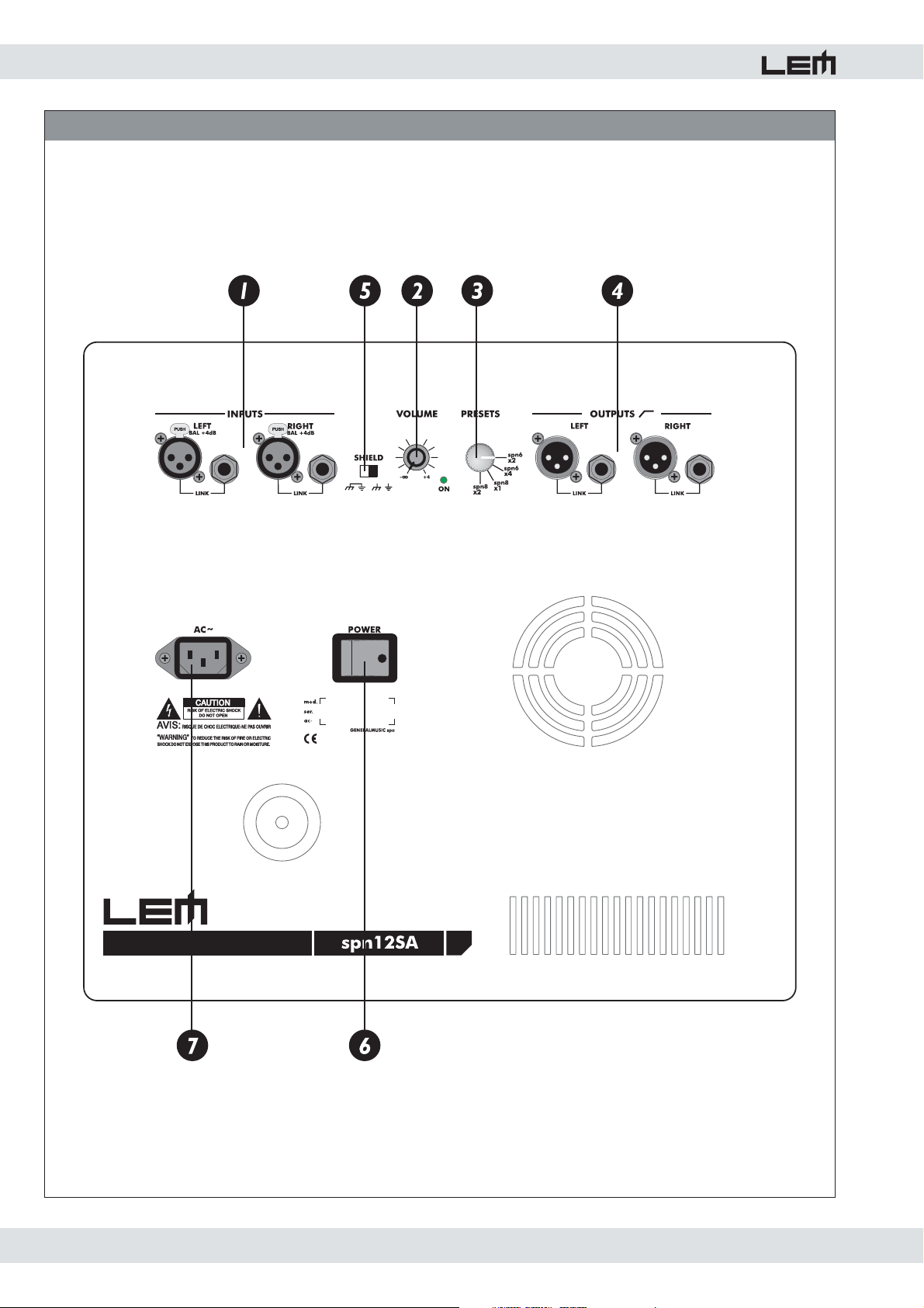
7. Pannello connessioni spn12sa (fig. 3)
1. Connettori STEREO XLR-F + JACK collegati in parallelo
(LINK) per l’ingresso ed il rilancio del segnale.
2. Controllo di livello del segnale inviato all’amplificatore
interno: la sensibilità massima (potenziometro ruotato
completamente verso destra) è di +4dB.
3. Selettore PRESET: i 4 PRESETS disponibili in spn12sa
sono stati preparati per consentire un bilanciamento ideale
del sub con diversi tipi di satellite. Essi includono, pertanto,
valori diversi per quanto riguarda i parametri del crossover,
i filtri di equalizzazione ed il livello del segnale inviato al sub
e ai satelliti.
- spn6x2: PRESET per l'utilizzo di un sub-woofer con
due spn6a (vedi figura 6).
- spn6x4: PRESET per l'utilizzo di un sub-woofer con
quattro spn6a (vedi figura 7).
- spn8x1: PRESET per l'utilizzo di un sub-woofer con
una spn8a. In questa configurazione, in un sistema
stereo vengono utilizzati 1 sub e 1 satellite per ciascun
lato (vedi figura 10).
- spn8x2: PRESET per l'utilizzo di un sub-woofer con
due spn8a (vedi figura 9).
4. Connettori STEREO XLR-M + JACK collegati in parallelo
(LINK) per il collegamento dei satelliti: queste uscite inviano
all'esterno il segnale originale filtrato dal crossover stereo
interno e vanno collegate all'ingresso dei satelliti.
5. Controllo di separazione della massa elettrica dalla massa
del telaio: il selettore SHIELD può consentire,in alcune
condizioni, di interrompere i ‘loop’ (ricicli) di massa e,
quindi, di eliminare ronzii od altri rumori di fondo.
6. Interruttore di accensione/spegnimento.
7. Presa per il cavo di alimentazione.
3
Page 4
spn series
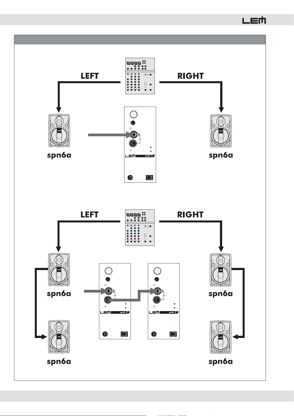
8. Sistemi spn (fig. 5, 6, 7, 8, 9 e 10)
Di seguito sono riportati degli esempi di sistemi di diffusione
che possono essere realizzati con i diffusori della serie spn,
utilizzando solo i satelliti oppure combinazioni di satelliti e
sub-woofer. Gli schemi di collegamento sono riportati nelle
figure 5, 6, 7, 8, 9 e 10.
a) Negozio di piccole dimensioni, personal monitors per PC
Musica a basso volume
2 x spn6a (potenza totale 300W)
b) Negozio di medie dimensioni, piccolo bar o ristorante,
LIVE P.A. di piccole dimensioni (piano bar)
Musica a basso volume
4 x spn6a (potenza totale 600W)
2 x spn6a + 1 x spn12sa (potenza totale 700W)
2 x spn8a (potenza totale 400W)
c) Negozio di dimensioni medio-grandi, bar o ristorante di
medie dimensioni, LIVE P.A. di dimensioni medie
Musica a medio volume, annunci
4 x spn6a + 1 x spn12sa (potenza totale 1000W)
4 x spn8a (potenza totale 800W)
2 x spn8a +1 x spn12sa (potenza totale 800W)
2 x spn8a + 2 x spn12sa (potenza totale 1200W)
d) Negozio o ristorante di grandi dimensioni,
disco bar, sala multimediale, sala conferenze
Musica a volume medio-alto, annunci, audio-video
8 x spn6a + 2 x spn12sa (potenza totale 2000W)
4 x spn8a + 2 x spn12sa (potenza totale 1600W)
e) Discoteca di piccole dimensioni,
LIVE P.A. di dimensioni medio-grandi
Musica ad alto volume
4 x spn8a + 4 x spn12sa (potenza totale 2400W)
8 x spn8a + 4 x spn12sa (potenza totale 3200W)
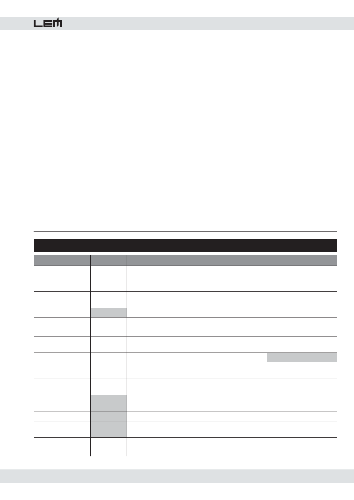
9. Specifiche Tecniche
AMPLIFICATORE
(1kHz, THD 1%)
DISTORSIONE (THD+N)
INGRESSO
ALIMENTAZIONE
SPL 1W/1m dB
MAX SPL dB
RISPOSTA IN
FREQUENZA
DISPERSIONE (OxV) °
FREQUENZA di
CROSSOVER
COMPONENTI
COSTRUZIONE
CONTROLLI
CONNESSIONI
DIMENSIONI mm (LxAxP)
PESO kg
Bassi
Sensibilità
Impedenza
Hz (-10dB)
HF driver
LF woofer
SPN SERIES • SPECIFICHE TECNICHE
SPN6A SPN8A SPN12SA
Alti
Hz
20
130
30kOhms (bilanciato) - 15kOhms (sbilanciato)
vedi targhetta informativa sull'apparato
90 93.5 94
112 116 120
50-25000 45-22000 33-200
100x100 90x60
3.5Hz @ 24dB/ott. 2.8Hz @ 24dB/ott. 150Hz @ 24/24dB/ott.
1" al neodimio
6½" al neodimio
Polipropilene
Griglia metallica - 2 punti di aggancio M6
Controllo di volume - Shield - Selettore PRESET
1 XLR-F + 1 JACK
196x301x185 260x410x264 410x470x480
4.7 8.2 28.0
20
180
Inferiore a 0.1%
+4dB
1"
8" al neodimio
400
12"
al neodimio
Multistrato con vernice nera
Griglia metallica
Input: 2 XLR-F + 2 JACK
Output: 2 XLR-M + 2 JACK
4
Page 5

spn series
1. Introduction
Congratulations for having chosen the spn series of
loudspeaker system! To make the best use of the system, please
read this manual thoroughly before operating the equipment.
2. Contents
3. Instructions for use and installation . . 5
1. Protection and maintenance. . . . . . . . . . . . . 5
2. Prevention of possible interference. . . . . . . 5
3. Connections . . . . . . . . . . . . . . . . . . . . . . . 5
4. Connector cables . . . . . . . . . . . . . . . . . . . .5
4. The spn series . . . . . . . . . . . . . . . . . 5
5. Installation . . . . . . . . . . . . . . . . . . . . 5
6. spn6a/spn8a connection panel . . . . . . 6
7. spn12sa connection panel . . . . . . . . . 6
8. spn systems . . . . . . . . . . . . . . . . . . . 7
9. Technical specifications . . . . . . . . . . . 7
3. Instructions for use and installation
1. Protection and maintenance.
To avoid jeopardizing correct operation, it is best not to
position the enclosure for long periods in exposed places
(damp, high temperature, etc.), in dusty environments
or those subject to strong vibrations. On this subject, it’s
advisable to always leave the protective grid mounted on
the enclosure. In the event of breakdown, do not open the
enclosure, but contact the nearest GENERALMUSIC Service
Centre.
2. Prevention of possible interference.
Avoid installing your equipment in the vicinity of radios,
televisions, etc., since this could cause noisy disturbance.
When connecting other equipment to your sound system,
pay close attention to so-called earth loops, which can
cause hum: in the event of interference, try using the
SHIELD switch on the enclosure’s control panel.
Check periodically that your cables are in good condition,
correctly wired and with perfectly efficient contacts: in fact
many problems and drawbacks (false contacts, ground
hum, crackles, etc.) are caused by the use of unsuitable or
damaged cables.
4. The spn series (fig. 1)
The spn series is a range of active loudspeaker systems
hosted in polypropylene (spn6a and spn8a) or plywood
(spn12sa) cabinets, designed for the use in fixed
installations, multimedia systems or small-size portable P.A.
systems. The series includes 3 different models.
- spn6: it is fitted with a 1” neodymium compression driver
on a spherical waveguide and with a 6.5” magnetically
shielded neodymium woofer. The built-in power module
includes one 130W PWM amplifier for the LOW section and
one 20W AB class amplifier for the HIGH section.
- spn8: it is fitted with a 1” compression driver on EWT horn
and with a 8” neodymium woofer. The built-in power module
includes one 180W PWM amplifier for the LOW section and
one 20W AB class amplifier for the HIGH section.
Both the power modules of spn6 and spn8 feature a
signal processor including active crossover, two separate
CLIP LIMITER circuits for the HF and LF sections and 4 EQ
PRESETS provided to optimize the speaker's response for
different applications.
- spn12s: it's a sub-woofer system fitted with a 12”
neodymium woofer with 2.5" coil. The built-in power module
includes a 400W amplifier, together with STEREO inputs and
outputs, STEREO active crossover and CLIP LIMITER circuit.
4 PRESETS are available for the use of the sub-woofer with
spn6a or spn8a.
5. Installation (fig. 1)
3. Connections.
Before connecting the enclosure to the mains supply, make
certain that the current corresponds with that indicated on
the rear of the unit (there is an allowance of ±10%). Always
connect the power cable to the enclosure before switching
on the enclosure and always remove it after having switched
off. Remember to always connect or disconnect other
equipment with the enclosure off and to always switch on
the mixer first, then the enclosure: in this manner, annoying
and often dangerous peaks are avoided.
4. Connector cables (fig. 4).
When connecting the enclosures to the mixer, make certain
to always use only screened signal cables made up of two
wires plus a braid/screen: the use of unscreened cables
could in fact probably cause annoying hum and noise.
spn6a and spn8a are fitted with two M6 threaded inserts
(one on the top side and another one on the bottom side)
for the use of dedicated LEM accessories for ceiling or wall
installation. Both models features a third M6 threaded inser t
to be used with a safety cable.
In addition, spn8a includes a housing on the bottom side
(with fixing clamp) for the installation on a standard speaker
stand (LEM SC-30).
Thanks to the shape of their cabinet, spn6a and spn8a
can be placed on the floor in horizontal position and used
as stage monitors.
spn12sa is fitted with an adapter for the use of a telescopic
loudspeaker stand (LEM SC-31) for the installation of the
satellite upon of the sub-woofer.
5
Page 6

spn series
6. spn6a / spn8a connection panel (fig. 2)
1. Input COMBO connector: according to the LINE/MIC
selector position (see point 3), you can connect line or
microphone signals. For the connection use BALANCED
signal cables with XLR or JACK connectors.
2. XLR-M connector producing the same signal that is
connected to the INPUT COMBO (LINK): it can be use to
daisy-chain several speakers together.
3. LINE/MIC selector: use this button to select the input
sensitivity of the built-in amplifier. In the LINE position
(button up) the input accepts line signals from equipment
with high-level outputs. In the MIC position (button down) the
input accepts the signal coming from a dynamic microphone
connected directly to the speaker without the need of an
external mixer.
Nota: use a sharp object (such as a pen or a small
screw-driver) to push this button. DO NOT CONNECT LINE
SIGNALS WHEN THE SELECTOR IS IN THE MIC POSITION:
the signal's high level could damage the amplifiers and
the speakers.
4. Level control of the signal sent to the built-in amplifiers:
the nominal sensitivity is different according to the LINE/MIC
selector's position (LINE +4dB / MIC -40dB).
5. PRESET selector: the 4 PRESETS available in spn6a
and spn8a have been prepared in order to provide the
loudspeaker systems with different acoustical responses
suitable for different applications, different kind of signal
and different tastes. Here below you can find a short
description that can help you in the choice.
- MUSIC: this PRESET has been prepared to provide the
best frequency response for the reproduction of recorded
music and is suitable for DJs, installations in public venues
and multimedia applications.
- LIVE: this PRESET provides a flat response, suitable for
LIVE setups and for any applications requiring the ‘natural’
response of the loudspeaker system.
- MONITOR: this is the PRESET to be chosen when the
spn are used as stage monitors. The frequency response
has been adjusted in order to compensate the reflections
from the floor, while the mid-high EQ provides a clear and
intelligible sound.
- VOICE: this PRESET can be used when you connect a
dynamic microphone directly to the speaker's input. The
equalization contained in this PRESET allows to get from the
microphone a brilliant and intelligible response even without
using a mixer.
7. Control for separating the electrical earth from that of the
chassis: under certain conditions, the SHIELD selector can
enable to break earth loops and to eliminate hum or other
annoying noises.
8. This LED glows when the unit is switched ON.
Note: it is normal for this LED keep glowing for a few
seconds when the units is switched off.
9. ON/OFF switch.
10. Mains cable (spn6a) / Power supply socket (spn8a).
7. spn12sa connection panel (fig. 3)
1. STEREO XLR-F + JACK sockets connected in parallel for
the signal input and linking.
2. Level control of the signal sent to the built-in amplifier:
the nominal sensitivity (knob fully rotated clock-wise) is
+4dB.
3. PRESET selector: the 4 PRESETS available in the
spn12sa have been prepared in order to provide an
optimal coupling of the sub-woofer with different satellites.
Therefore, they include different parameters for the
crossover filters, the EQ filters and the level of the signal
sent to the satellites.
- spn6x2: PRESET for the use of one sub-woofer with
two spn6a (see fig. 6).
- spn6x4: PRESET for the use of one sub-woofer with
four spn6a (see fig. 7).
- spn8x1: PRESET for the use of one sub-woofer with
one spn8a. In this configuration, a stereo system
includes 1 sub and 1 satellite for each side (see fig. 10).
- spn8x2: PRESET for the use of one sub-woofer with
two spn8a (see fig. 9).
4. STEREO XLR-M + JACK sockets connected in parallel for
the connection of the satellites: they send out the signal
filtered by the built-in STEREO crossover and must be
connected to the satellite's inputs.
5. Control for separating the electrical earth from that of the
chassis: under certain conditions, the SHIELD selector can
enable to break earth loops and to eliminate hum or other
annoying noises.
6. ON/OFF switch.
7. Power supply socket.
6. LIMIT LED: it indicates when the CLIP LIMITER starts
operating following the detection of a too high signal
level being fed to the amplifiers. In this case, the LIMITER
lowers the signal level to avoid damage to the enclosure
components and amplifier clipping.
6
Page 7
spn series
8. spn systems (fig. 5, 6, 7, 8, 9 e 10)
Here below you can find some examples of spn setups
including only the satellites or combinations of satellites and
sub-woofers. The connection schemes are shown in fig. 5,
6, 7, 8, 9 and 10.
a) Small retail store, personal monitors for PC
Low level music
2 x spn6a (total power 300W)
b) Mid-size retail store, small bar or restaurant,
small size LIVE P.A. (piano bar)
Low level music
4 x spn6a (total power 600W)
2 x spn6a + 1 x spn12sa (total power 700W)
2 x spn8a (total power 400W)
c) Medium-to-large retail store, mid-size bar or
restaurant, mid-size LIVE P.A.
Mid level music, voice paging
4 x spn6a + 1 x spn12sa (total power 1000W)
4 x spn8a (total power 800W)
2 x spn8a +1 x spn12sa (total power 800W)
2 x spn8a + 2 x spn12sa (total power 1200W)
d) Large retail store, restaurant, disco bar
multimedia venue or conference room
Mid-high level music, voice-paging, audio-video
8 x spn6a + 2 x spn12sa (total power 2000W)
4 x spn8a + 2 x spn12sa (total power 1600W)
e) Small disco, big LIVE P.A.
High level music
4 x spn8a + 4 x spn12sa (total power 2400W)
8 x spn8a + 4 x spn12sa (total power 3200W)
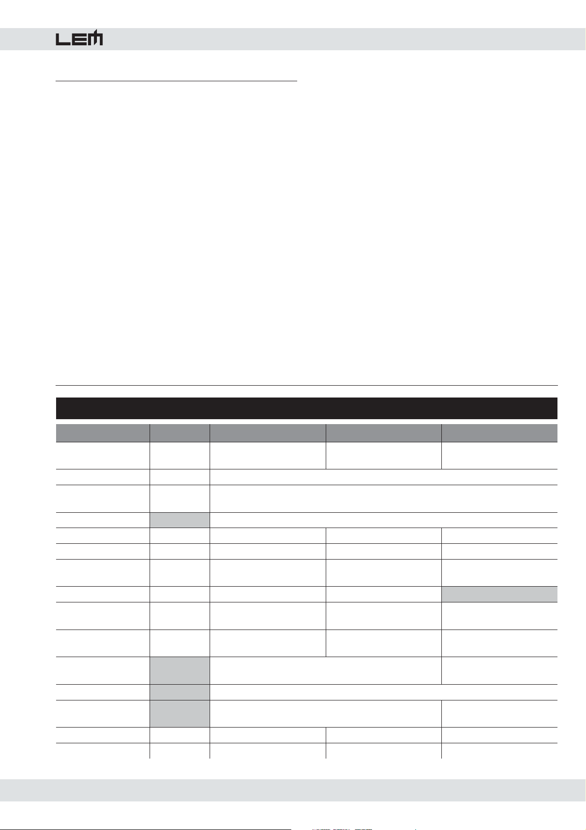
7. Technical Specifications
SPN SERIES • TECHNICAL SPECIFICATIONS
POWER AMPLIFIER
(1kHz, THD 1%)
DISTORTION (THD+N)
INPUT
POWER SUPPLY
SPL 1W/1m dB
MAX SPL dB
FREQUENCY
RESPONSE
DISPERSION (OxV) °
CROSSOVER
FREQUENCY
COMPONENTS
CABINET
CONTROLS
CONNECTIONS
DIMENSIONS mm (WxHxD)
WEIGHT kg
High
Low
Sensitivity
Impedance
Hz (-10dB)
HF driver
LF woofer
Hz
SPN6A SPN8A SPN12SA
20
130
30kOhms (balanced) - 15kOhms (unbalanced)
see label on the apparatus
90.5 93.5 94
112 116 120
50-25000 45-22000 33-200
100x100 90x60
3.5Hz @ 24dB/oct. 2.8Hz @ 24dB/oct. 150Hz @ 24/24dB/oct.
1" neodymium
6½" neodymium
High-density polypropylene
Metal grille - 2 x M6 flying points
Volume control - Shield - PRESET selector
1 XLR-F + 1 JACK
196x301x185 260x410x264 410x470x480
4.7 8.2 28.0
20
180
Less than 0.1%
+4dB
1"
8" neodymium
400
12" neodymium
Plywood with black painting
Metal grille
Input: 2 XLR-F + 2 JACK
Output: 2 XLR-M + 2 JACK
7
Page 8
spn series
FIG. 1 - THE SPN SERIES
spn6a
spn8a
spn12sa
8
Page 9

FIG. 2 - CONNECTOR PANELS
spn series
9
Page 10
spn series
FIG. 3 - CONNECTOR PANELS
10
Page 11
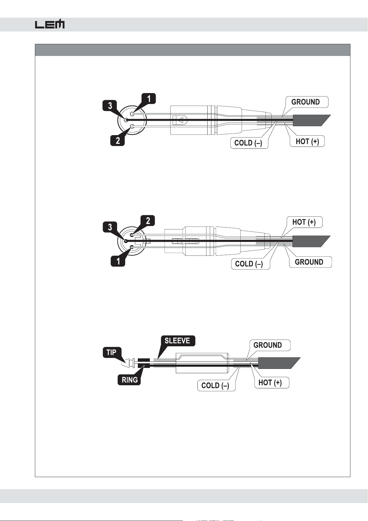
FIG. 4 - CONNECTION CABLES
Balanced XLR-M
XLR-M bilanciato
spn series
Balanced XLR-F
XLR-F bilanciato
Balanced JACK
JACK bilanciato
11
Page 12
spn series
FIG. 5 - CONNECTION EXAMPLES
12
Page 13
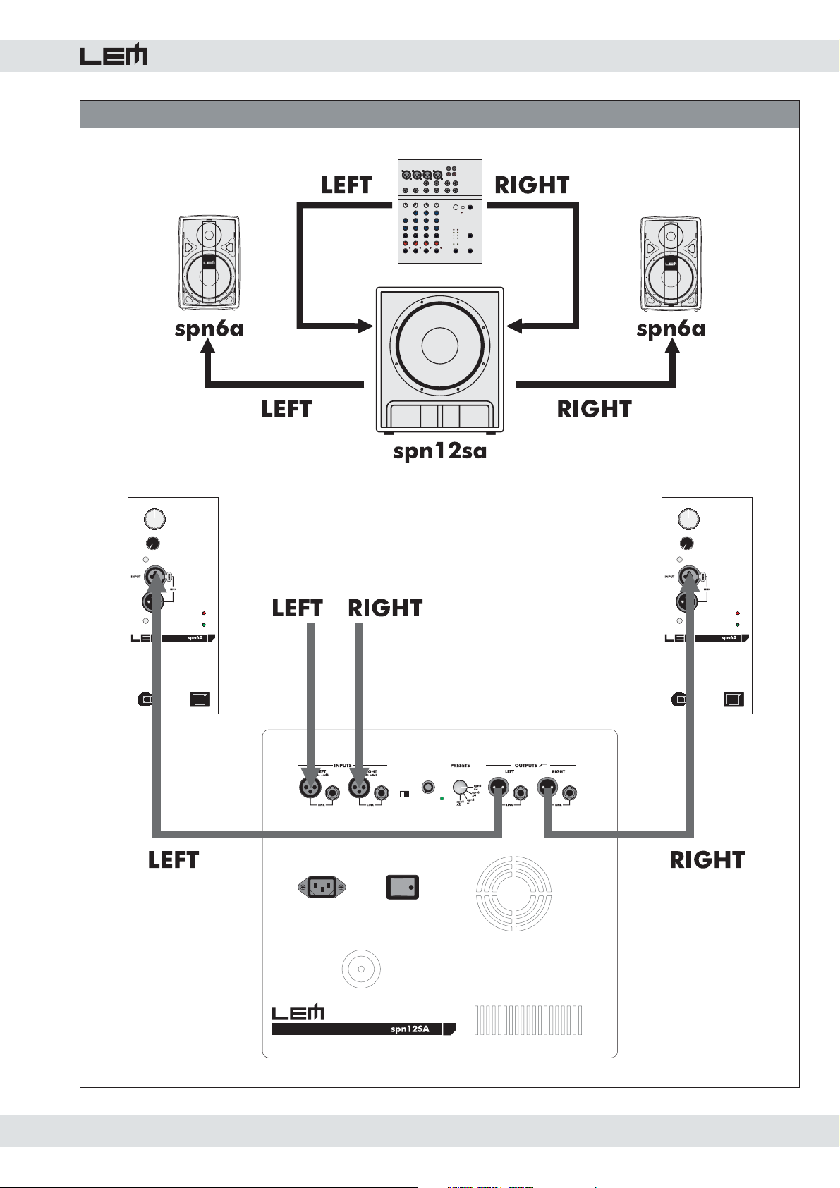
FIG. 6 - CONNECTION EXAMPLES
spn series
13
Page 14
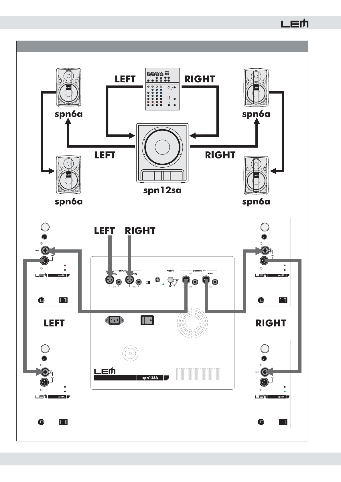
spn series
FIG. 7 - CONNECTION EXAMPLES
14
Page 15
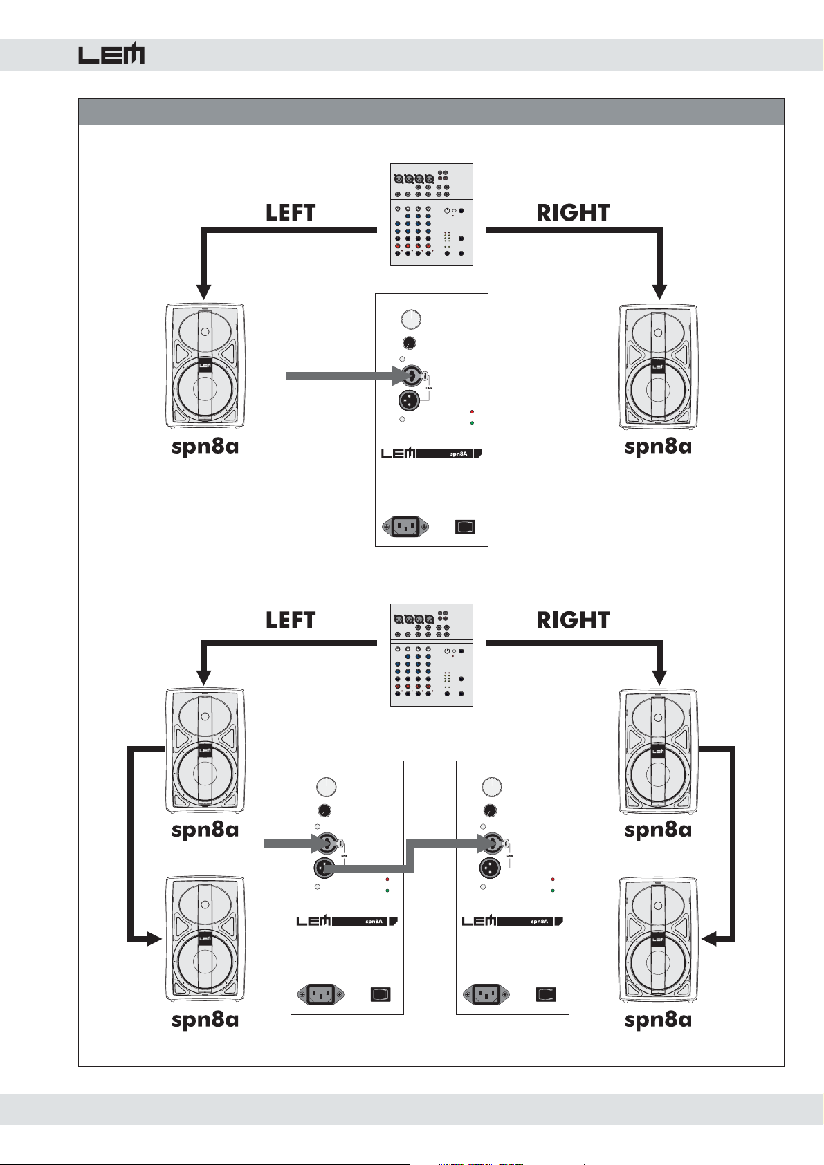
FIG. 8 - CONNECTION EXAMPLES
spn series
15
Page 16
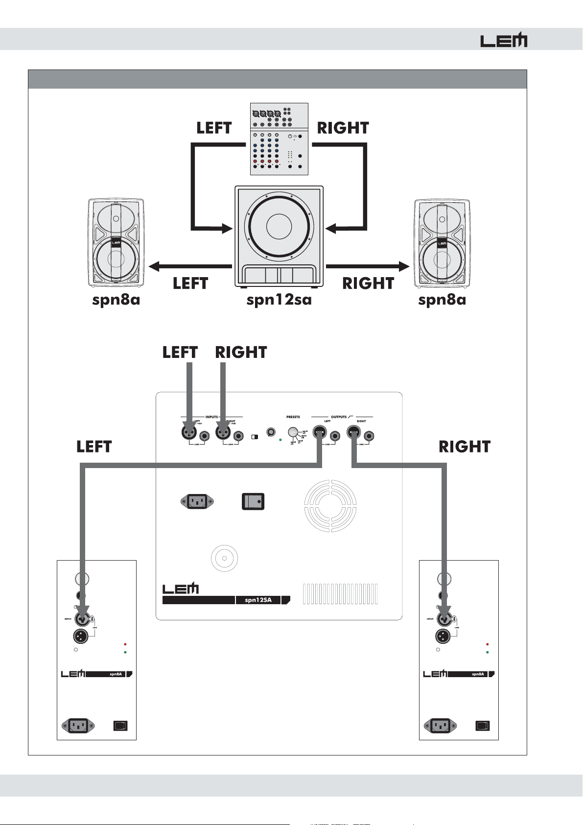
spn series
FIG. 9 - CONNECTION EXAMPLES
16
Page 17
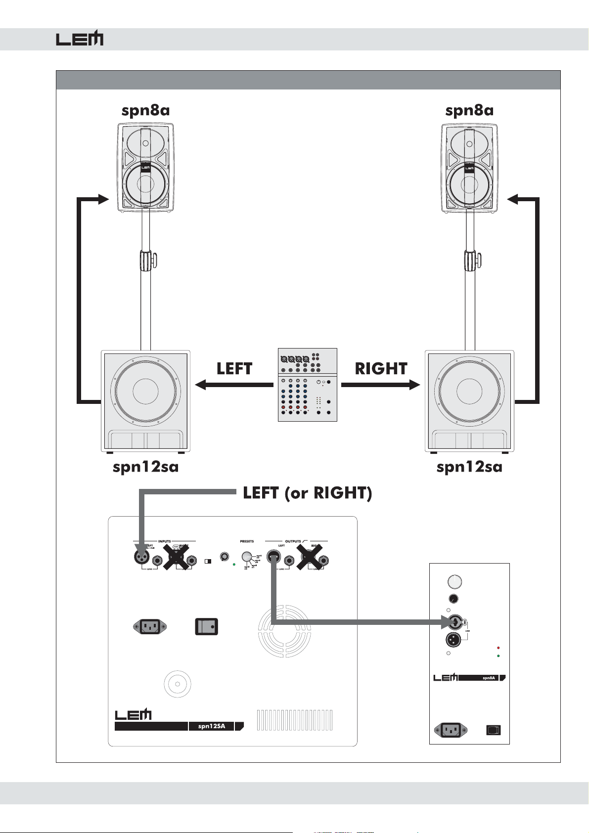
FIG. 10 - CONNECTION EXAMPLES
spn series
17
Page 18

Le informazioni contenute in questo documento sono state at ten ta men te redatte e controllate. Tuttavia non è assunta
alcuna re spon sa bi li tà per eventuali inesattezze.
Tutti i diritti sono riservati e questo documento non può essere copiato, fotocopiato, riprodotto per intero o in parte
senza previo consenso scritto della GENERALMUSIC S.p.A.
GENERALMUSIC si riserva il diritto di apportare senza preavviso cam bia men ti e modifi che estetiche, funzionali o
di design a ciascun proprio prodotto.
GENERALMUSIC non assume alcuna responsabilità sull’uso o sul l’ap pli ca zio ne dei prodotti o dei circuiti qui
descritti.
STAMPATO IN ITALIA
The information contained in this publication has been carefully prepared and checked. However no responsibility
will be taken for any errors.
All rights are reserved and this document cannot be copied, photocopied or reproduced in part or completely without
written consent being obtained in advance from GENERALMUSIC S.p.A.
GENERALMUSIC reserves the right to make any aesthetic, functional or design modifi cation to any of its products
without any prior notice.
GENERALMUSIC assumes no responsibility for the use or application of the products or circuits described
herein.
PRINTED IN ITALY
 Loading...