

Page 1

Index
PROCON 400 Test Procedure2
PROCON 750 Test Procedure2
PROCON 950 Test Procedure
3
PROCON 1100 Test Procedure
3
PROCON 1250 Test Procedure
4
4 PROCON 1500 Test Procedure
5
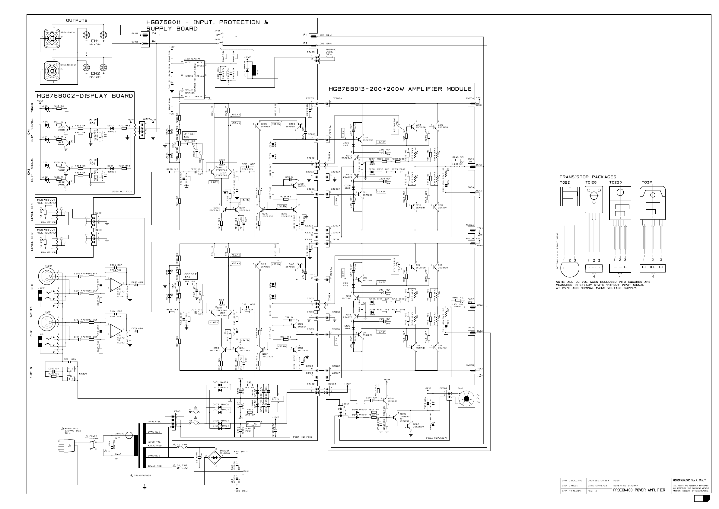
PROCON 400 Schematic
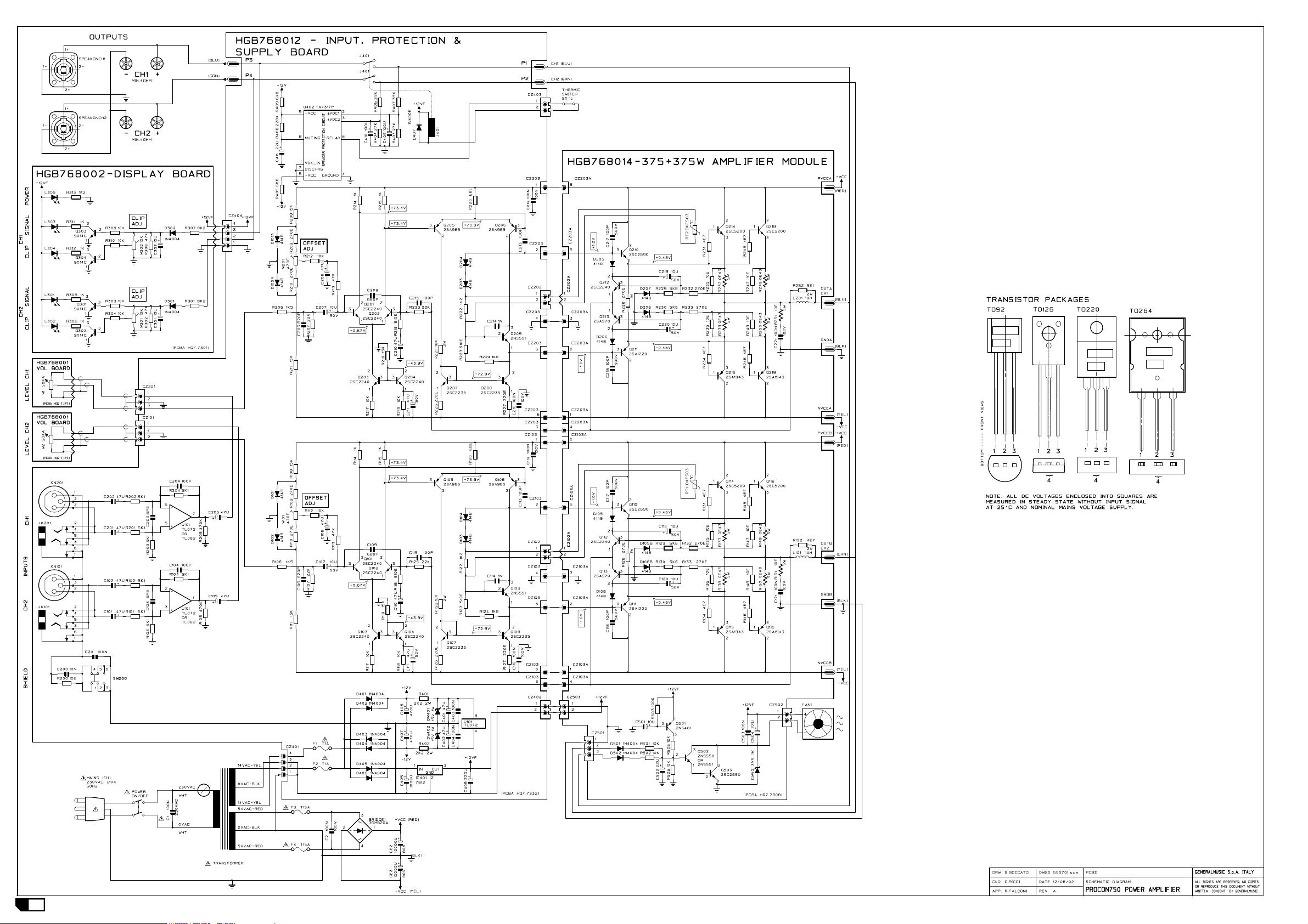
PROCON 750 Schematic
6
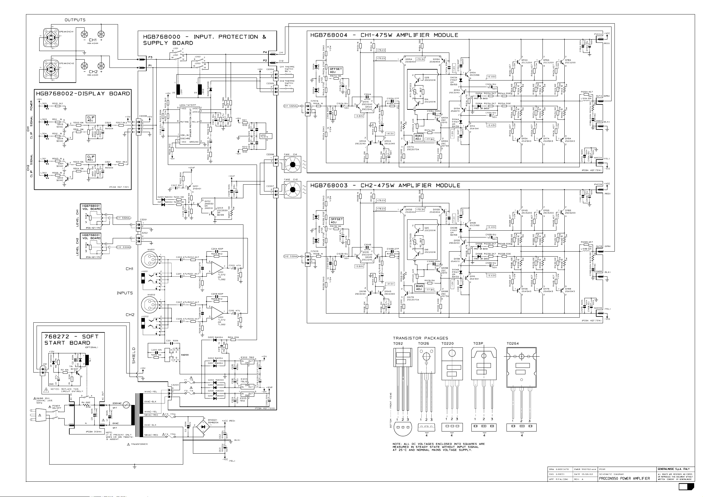
PROCON 950 Schematic
7
8
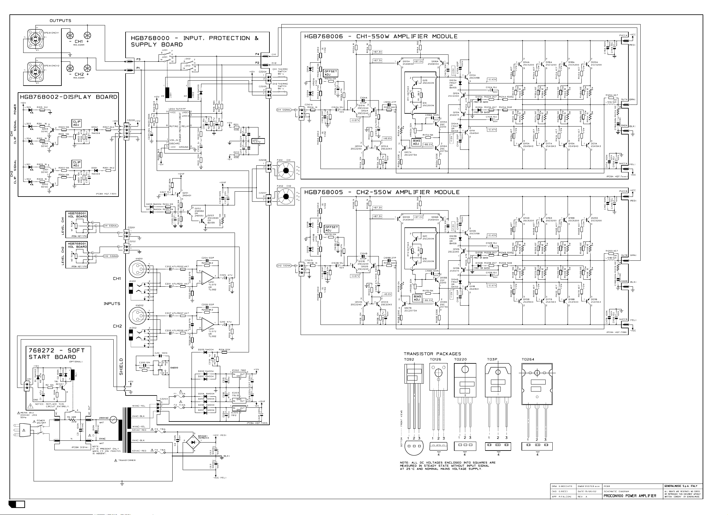
PROCON 1100 Schematic
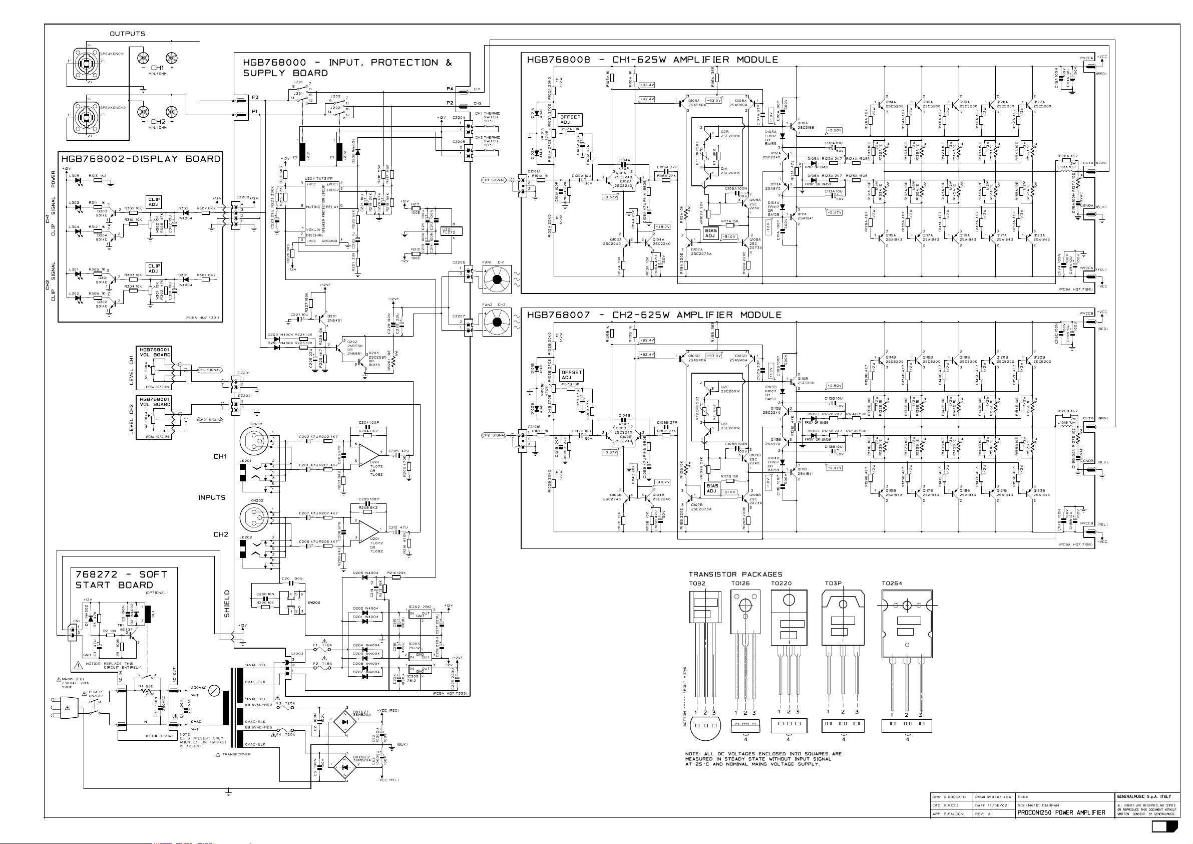
PROCON 1250 Schematic
9
PROCON 1500 Schematic
10
11
Spare Part List
SERVICE MANUAL
®
Notice
Service must be carried out by qualified personnel only. Any tampering carried out by unqualified personnel during the guarantee period
✔
will forfeit the right to guarantee.
For a correct operation of the instrument, after having switched off, be careful to wait at least 3 seconds before switching on again.
✔
To improve the device's specifications, the schematic diagrams may be subject to change without prior notice.
✔
All components marked by this symbol have special safety characteristics, when replacing any of these components use only
manufacturer's specified parts.
The (µ) micro symbol of capacitance value is substituted by U.
✔
Ω) omega symbol of resistance value is substituted by E.
The (
✔
The electrolytic capacitors are 25Vdc rated voltage unless otherwise specified.
✔
All resistors are 1/8W unless otherwise specified.
✔
All switches shown in the "OFF" position. All DC voltages measured to ground with a voltmeter 20KOhm/V.
✔
✔
✔
✔
✔
Soldering point.
Male connector.
Female connector.
M/F faston connector.
ATTENTION Observe precautions when handling electrostatic sensitive devices.
Supply voltage. Logic supply ground.
Test point.
Flag joined with one or more flags
with the same signal name inscribed.
Analog supply ground.
Chassis ground.
Earth ground.
code 270266
GENERALMUSIC S.p.A. Sales Division: 47842 S.Giovanni in Marignano (RN) ITALY - Via delle Rose, 12
✒
Phone +39(0)541/959511 - Fax +39(0)541/957404 - Internet: www.generalmusic.com
☎
11
1
11
Page 2
PROCON400 - Test procedures andPROCON400 - Test procedures and
PROCON400 - Test procedures and
PROCON400 - Test procedures andPROCON400 - Test procedures and
adjustmentsadjustments
adjustments
adjustmentsadjustments
PRECAUTIONPRECAUTION
PRECAUTION
PRECAUTIONPRECAUTION
• To prevent short circuit during any test, the oscilloscope must
be EARTH INSULATED, this occurs because some test require to
connect its probe to the amplifier output, non-compliance may
cause damages to oscilloscope inputs circuitry.
• Before removing or installing any modules and connectors,
disconnect the amplifier from AC MAINS and measure the DC
supply voltages across each of the power supply capacitors. If
your measurement on any of the caps is greater than 10Vdc,
connect a 100E 30W resistor across the applicable caps to
discharge them for your safety. Remember to remove the
discharge resistor immediately after discharging caps. Do not
power up the amplifier with the discharge resistor connected.
• Do not check the amplifier with the speakers connected use the
appropriate load resistors only.
• BE CAREFUL increasing the Variac you must not exceed the
nominal mains voltage plus its tolerance (see specifications) any
upper voltage can be cause of damage.
VISUAL CHECKVISUAL CHECK
VISUAL CHECK
VISUAL CHECKVISUAL CHECK
• Use compressed air to clear dust in the amplifier chassis.
• Before proceed to supply the amplifier check visually the
internal assembly, if appears an evident damage find the most
possible reasons that cause it.
• Check the wiring cables for possible interruptions or shorts.
• If the damage has burnt a printed circuit board don’t try to
repair it, replace with a new one.
TESTING GEARTESTING GEAR
TESTING GEAR
TESTING GEARTESTING GEAR
• Audio Generator
• Dual Trace Oscilloscope
• Digital Multimeter
• 4E 300W, 8E 200W, 100E 30W resistors
• Variac
SETUPSETUP
SETUP
SETUPSETUP
• Connect the Variac between the Mains and the amplifier and set
it at zero voltage.
• Turn full counter-clockwise the LEVEL potentiometers.
• Connect the audio generator to the channel inputs and set it to
1KHz 775mVrms (0dBm) sinusoidal signal.
• Connect the two scope traces to the amplifier outputs, before
the relay, and set them in DC at 20V/div. 2mS/div.
SUPPLY CHECKSUPPLY CHECK
SUPPLY CHECK
SUPPLY CHECKSUPPLY CHECK
• Verify with the Multimeter the insulation between the heatsinks
and all transistor collectors mounted on them; placing the
multimeter tips between the screw heads and the collector pins
you can exclude an erroneus reading due to the insulation of the
heatsink anodization.
• Verify with the Multimeter the NTC (RT1 or RT2) and R122 or
R222 paralleled resistor value, it must be about 1.17K (at 25°c).
• Turn on the Amplifier.
• Remove the transformer secondary fuses, set the Variac to the
nominal mains voltage, check with the Multimeter the AC supply
voltages:
F1-F2 = 28±2Vac.
F3-F4 = 85±8Vac.
• Re-set the Variac at zero voltage, turn off the amplifier and put
the fuses back on its holders.
• Set up the Variac slowly monitoring the oscilloscope screen, it
should display no signal; if you notice a DC voltage or a
protection trips check the amplifier as suggested in the ADVICES
section.
• As soon as the +12VF supply circuit reaches its nominal value,
all cooling fans run at their minimum and the speaker output
relay (J401) switches.
• When the Variac ac voltage reaches the nominal voltage verify
the DC supplies as follow:
+VCC = +57±5Vdc
-VCC = -57±5Vdc
U101 pin 8 = +15±1Vdc
U101 pin 4 = -15±1Vdc
U401 pin 3 = +12±1Vdc
• If one or more voltages don’t correspond, check the rectifiers,
capacitors and transformers disconnecting them from circuitry.
CHANNEL CHECKCHANNEL CHECK
CHANNEL CHECK
CHANNEL CHECKCHANNEL CHECK
• Be sure you have disconnected the load resistor.
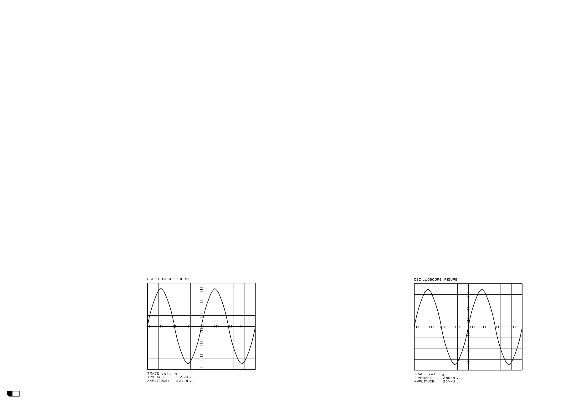
• Increasing the input signal also the output signal raise
accordingly, it must be symmetrical without visible distortion or
oscillation as shown in figure (note: the figure is representative
don`t refer to the levels displayed). If there is a distortion read
the section ADVICES.
• When the input signal exceeds -18dBm (~8Vpp on output) the
SIGNAL led lights and the fan turns at its maximum speed.
• Firstly you must check the channel without load, afterwards
you must repeat the check with the loads attached, the following
table reports the approx. maximum level obtainable with this
amplifier:
out level in level
no load 110Vpp +4.5dB
1CH 8E 104Vpp +4dB
1CH 4E 92Vpp +3dB
2CH 8E 90Vpp +3dB
2CH 4E 80Vpp +2dB
CLIP LED ADJUSTMENTCLIP LED ADJUSTMENT
CLIP LED ADJUSTMENT
CLIP LED ADJUSTMENTCLIP LED ADJUSTMENT
• Check if the clip led lights at approx. 0dBm on input level, if
necessary adjust the trimmer W301 and W302 on display board.
OFFSET ADJUSTMENTOFFSET ADJUSTMENT
OFFSET ADJUSTMENT
OFFSET ADJUSTMENTOFFSET ADJUSTMENT
• Set the input level at minimum (no signal), the output dc offset
voltage must be within ±20mV, if necessary adjust the W201
(CH1) or W201 (CH2) trimmers to be within this threshold.
BIAS ADJUSTMENTBIAS ADJUSTMENT
BIAS ADJUSTMENT
BIAS ADJUSTMENTBIAS ADJUSTMENT
• No bias adjustment is necessary for this amplifier circuitry.
ADVICESADVICES
ADVICES
ADVICESADVICES
• If you have determinate that the problem is a short on a rail,
you must check the output transistors.
• To determine which transistor devices are bad, use a soldering
iron to lift one leg of each emitter pin and measure the emittercollector resistance on each device. Unsolder and lift one leg of
each base pin and check the base-collector resistance of each
transistor and replace any that measure as a short.
• If all the transistors are OK, unsolder and lift one leg of each
diode and check them.
• Check the circuit board for open foil traces.
• Use the Multimeter as Ohm-meter to check the resistors,
particularly the base and emitter resistors of damaged transistor.
• If the input sinewave appears to be distorted during the
negative cycle, you can assume that the problem is located
somewhere in the circuitry of the positive rail.
• If the positive cycle appears distorted, you can assume that the
problem is in the circuitry of the negative rail.
• The dc voltages printed on the schematics are measured with
the amplifier in steady state without input signal and nominal
mains voltage supply, it can be useful to localize a damage.
FIGURESFIGURES
FIGURES
FIGURESFIGURES
PROCON750 - Test procedures andPROCON750 - Test procedures and
PROCON750 - Test procedures and
PROCON750 - Test procedures andPROCON750 - Test procedures and
adjustmentsadjustments
adjustments
adjustmentsadjustments
PRECAUTIONPRECAUTION
PRECAUTION
PRECAUTIONPRECAUTION
• To prevent short circuit during any test, the oscilloscope must
be EARTH INSULATED, this occurs because some test require to
connect its probe to the amplifier output, non-compliance may
cause damages to oscilloscope inputs circuitry.
• Before removing or installing any modules and connectors,
disconnect the amplifier from AC MAINS and measure the DC
supply voltages across each of the power supply capacitors. If
your measurement on any of the caps is greater than 10Vdc,
connect a 100E 60W resistor across the applicable caps to
discharge them for your safety. Remember to remove the
discharge resistor immediately after discharging caps. Do not
power up the amplifier with the discharge resistor connected.
• Do not check the amplifier with the speakers connected use the
appropriate load resistors only.
• BE CAREFUL increasing the Variac you must not exceed the
nominal mains voltage plus its tolerance (see specifications) any
upper voltage can be cause of damage.
VISUAL CHECKVISUAL CHECK
VISUAL CHECK
VISUAL CHECKVISUAL CHECK
• Use compressed air to clear dust in the amplifier chassis.
• Before proceed to supply the amplifier check visually the
internal assembly, if appears an evident damage find the most
possible reasons that cause it.
• Check the wiring cables for possible interruptions or shorts.
• If the damage has burnt a printed circuit board don’t try to
repair it, replace with a new one.
TESTING GEARTESTING GEAR
TESTING GEAR
TESTING GEARTESTING GEAR
• Audio Generator
• Dual Trace Oscilloscope
• Digital Multimeter
• 4E 500W, 8E 300W, 100E 60W resistors
• Variac
SETUPSETUP
SETUP
SETUPSETUP
• Connect the Variac between the Mains and the amplifier and set
it at zero voltage.
• Turn full counter-clockwise the LEVEL potentiometers.
• Connect the audio generator to the channel inputs and set it to
1KHz 775mVrms (0dB) sinusoidal signal.
• Connect the two scope traces to the amplifier outputs, before
the relay, and set them in DC at 20V/div. 2mS/div.
SUPPLY CHECKSUPPLY CHECK
SUPPLY CHECK
SUPPLY CHECKSUPPLY CHECK
• Verify with the Multimeter the insulation between the heatsinks
and all transistor collectors mounted on them; placing the
multimeter tips between the screw heads and the collector pins
you can exclude an erroneus reading due to the insulation of the
heatsink anodization.
• Verify with the Multimeter the NTC (RT1 or RT2) and R122 or
R222 paralleled resistor value, it must be about 1.17K (at 25°c).
• Turn on the Amplifier.
• Remove the transformer secondary fuses, set the Variac to the
nominal mains voltage, check with the Multimeter the AC supply
voltages:
F1-F2 = 28±2Vac.
F3-F4 = 104±10Vac.
• Re-set the Variac at zero voltage, turn off the amplifier and put
the fuses back on its holders.
• Set up the Variac slowly monitoring the oscilloscope screen, it
should display no signal; if you notice a DC voltage or a
protection trips check the amplifier as suggested in the ADVICES
section.
• As soon as the +12VF supply circuit reaches its nominal value,
all cooling fans run at their minimum and the speaker output
relay (J401) switches.
• When the Variac ac voltage reaches the nominal voltage verify
the DC supplies as follow:
+VCC = +75±5Vdc
-VCC = -75±5Vdc
U101 pin 8 = +15±1Vdc
U101 pin 4 = -15±1Vdc
U401 pin 3 = +12±1Vdc
• If one or more voltages don’t correspond, check the rectifiers,
capacitors and transformers disconnecting them from circuitry.
CHANNEL CHECKCHANNEL CHECK
CHANNEL CHECK
CHANNEL CHECKCHANNEL CHECK
• Be sure you have disconnected the load resistor.
• Increasing the input signal also the output signal raise
accordingly, it must be symmetrical without visible distortion or
oscillation as shown in figure (note: the figure is representative
don`t refer to the levels displayed). If there is a distortion read
the section ADVICES.
• When the input signal exceeds -18dBm (~8Vpp on output) the
SIGNAL led lights and the fan turns at its maximum speed.
• Firstly you must check the channel without load, afterwards
you must repeat the check with the loads attached, the following
table reports the approx. maximum level obtainable with this
amplifier:
out level in level
no load 148Vpp +7dBm
1CH 8E 128Vpp +5.5dBm
1CH 4E 120Vpp +4.5dBm
2CH 8E 120Vpp +5dBm
2CH 4E 104Vpp +4dBm
CLIP LED ADJUSTMENTCLIP LED ADJUSTMENT
CLIP LED ADJUSTMENT
CLIP LED ADJUSTMENTCLIP LED ADJUSTMENT
• Check if the clip led lights at approx. 0dBm on input level, if
necessary adjust the trimmer W301 and W302 on display board.
OFFSET ADJUSTMENTOFFSET ADJUSTMENT
OFFSET ADJUSTMENT
OFFSET ADJUSTMENTOFFSET ADJUSTMENT
• Set the input level at minimum (no signal), the output dc offset
voltage must be within ±20mV, if necessary adjust the W201
(CH1) or W201 (CH2) trimmers to be within this threshold.
BIAS ADJUSTMENTBIAS ADJUSTMENT
BIAS ADJUSTMENT
BIAS ADJUSTMENTBIAS ADJUSTMENT
• No bias adjustment is necessary for this amplifier circuitry.
ADVICESADVICES
ADVICES
ADVICESADVICES
• If you have determinate that the problem is a short on a rail,
you must check the output transistors.
• To determine which transistor devices are bad, use a soldering
iron to lift one leg of each emitter pin and measure the emittercollector resistance on each device. Unsolder and lift one leg of
each base pin and check the base-collector resistance of each
transistor and replace any that measure as a short.
• If all the transistors are OK, unsolder and lift one leg of each
diode and check them.
• Check the circuit board for open foil traces.
• Use the Multimeter as Ohm-meter to check the resistors,
particularly the base and emitter resistors of damaged transistor.
• If the input sinewave appears to be distorted during the
negative cycle, you can assume that the problem is located
somewhere in the circuitry of the positive rail.
• If the positive cycle appears distorted, you can assume that the
problem is in the circuitry of the negative rail.
• The dc voltages printed on the schematics are measured with
the amplifier in steady state without input signal and nominal
mains voltage supply, it can be useful to localize a damage.
FIGURESFIGURES
FIGURES
FIGURESFIGURES
22
2
22
Page 3
PROCON950 - Test procedures andPROCON950 - Test procedures and
PROCON950 - Test procedures and
PROCON950 - Test procedures andPROCON950 - Test procedures and
adjustmentsadjustments
adjustments
adjustmentsadjustments
PRECAUTIONPRECAUTION
PRECAUTION
PRECAUTIONPRECAUTION
• To prevent short circuit during any test, the oscilloscope must
be EARTH INSULATED, this occurs because some test require to
connect its probe to the amplifier output, non-compliance may
cause damages to oscilloscope inputs circuitry.
• Before removing or installing any modules and connectors,
disconnect the amplifier from AC MAINS and measure the DC
supply voltages across each of the power supply capacitors. If
your measurement on any of the caps is greater than 10Vdc,
connect a 100E 70W resistor across the applicable caps to
discharge them for your safety. Remember to remove the
discharge resistor immediately after discharging caps. Do not
power up the amplifier with the discharge resistor connected.
• Do not check the amplifier with the speakers connected use the
appropriate load resistors only.
• BE CAREFUL increasing the Variac you must not exceed the
nominal mains voltage plus its tolerance (see specifications) any
upper voltage can be cause of damage.
VISUAL CHECKVISUAL CHECK
VISUAL CHECK
VISUAL CHECKVISUAL CHECK
• Use compressed air to clear dust in the amplifier chassis.
• Before proceed to supply the amplifier check visually the
internal assembly, if appears an evident damage find the most
possible reasons that cause it.
• Check the wiring cables for possible interruptions or shorts.
• If the damage has burnt a printed circuit board don’t try to
repair it, replace with a new one.
TESTING GEARTESTING GEAR
TESTING GEAR
TESTING GEARTESTING GEAR
• Audio Generator
• Dual Trace Oscilloscope
• Digital Multimeter
• 4E 600W, 8E 400W, 100E 70W resistors
• Variac
• Digital Thermometer (not indispensable)
SETUPSETUP
SETUP
SETUPSETUP
• Connect the Variac between the Mains and the amplifier and
set it at zero voltage.
• Turn full counter-clockwise the LEVEL potentiometers.
• Connect the audio generator to the channel inputs and set it to
1KHz 775mVrms (0dBm) sinusoidal signal.
• Connect the two scope traces to the amplifier outputs, before
the relay, and set them in DC at 20V/div. 2mS/div.
SUPPLY CHECKSUPPLY CHECK
SUPPLY CHECK
SUPPLY CHECKSUPPLY CHECK
• Verify with the Multimeter the insulation between the heatsinks
and all transistor collectors mounted on them; placing the
multimeter tips between the screw heads and the collector pins
you can exclude an erroneus reading due to the insulation of the
heatsink anodization.
• Verify with the Multimeter the NTC (RT1) and R1 paralleled
resistor value, it must be about 7KE (at 25°c).
• Turn on the Amplifier.
• Remove the transformer secondary fuses, set the Variac to the
nominal mains voltage, check with the Multimeter the AC supply
voltages:
F1-F2 = 28±2Vac.
F3-F4 = 119±12Vac.
• Re-set the Variac at zero voltage, turn off the amplifier and put
the fuses back on its holders.
• Set up the Variac slowly monitoring the oscilloscope screen, it
should display no signal; if you notice a DC voltage or a
protection trips check the amplifier as suggested in the ADVICES.
• As soon as the +12VF supply circuit reaches its nominal value,
all cooling fans run at their minimum and the speaker output
relais (J201-202) switch.
• When the Variac ac voltage reaches the nominal voltage verify
the DC supplies as follow:
+VCC = +81±6Vdc
-VCC = -81±6Vdc
U201 pin 8 = +12±0.5Vdc
U201 pin 4 = -12±0.5Vdc
U202 pin 3 = +12±0.5Vdc
• If one or more voltages don’t correspond, check the rectifiers,
capacitors and transformers disconnecting them from circuitry.
CHANNEL CHECKCHANNEL CHECK
CHANNEL CHECK
CHANNEL CHECKCHANNEL CHECK
• Be sure you have disconnected the load resistor.
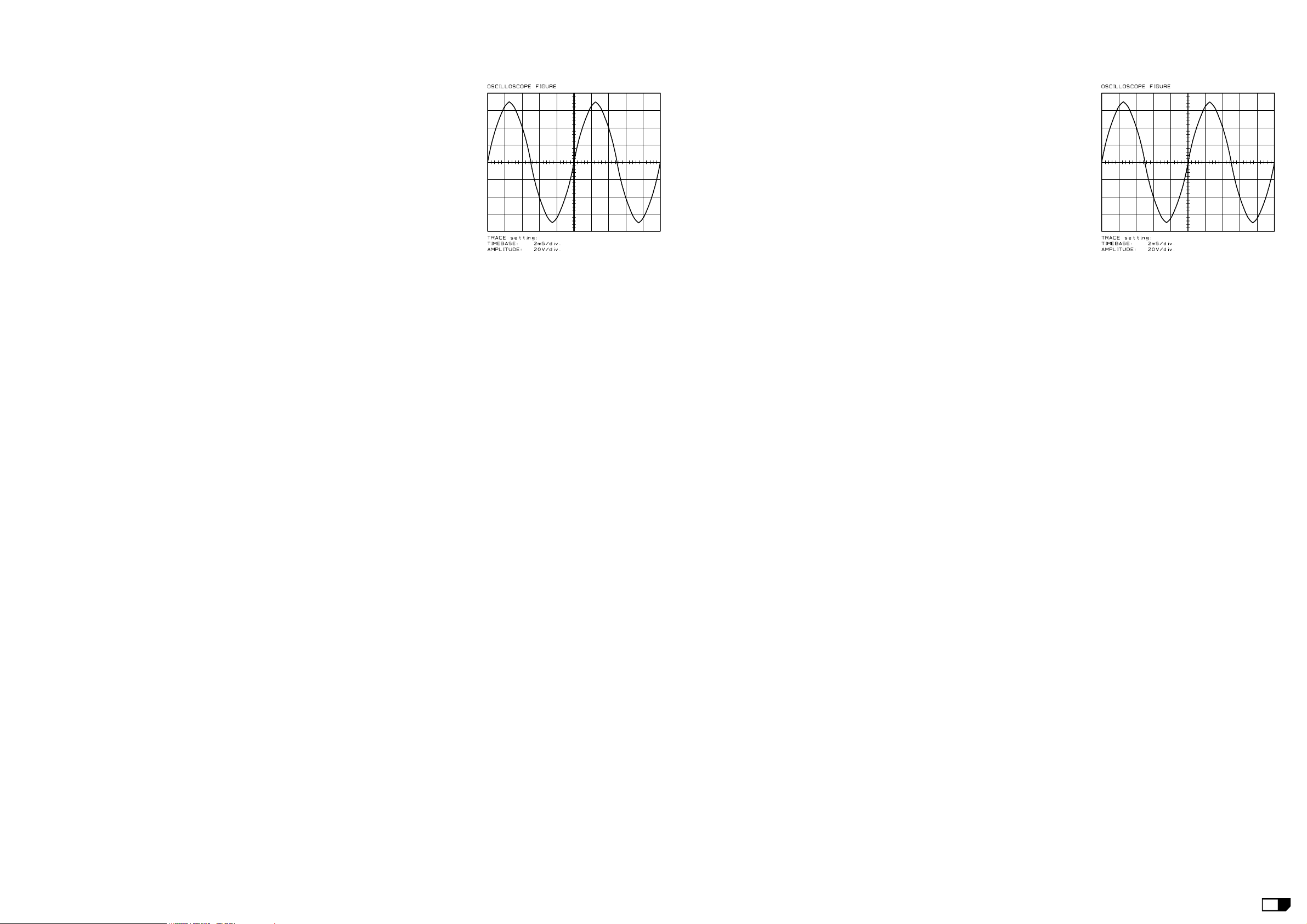
• Increasing the input
signal also the output
signal raise accordingly,
it must be symmetrical
without visible distortion
or oscillation as shown in
figure (note: the figure
is representative don`t
refer to the levels displayed). If there is a distortion read the section
ADVICES.
• When the input signal
exceeds -25dBm (9Vpp
on output) the SIGNAL
led lights and the fans
turn at their maximum
speed.
• Firstly you must check the channel without load, afterwards
you must repeat the check with the loads attached, the following
table reports the approx. maximum level obtainable with this
amp:
out level in level
no load 160Vpp +0dBm
1CH 8E 158Vpp -0.7dBm
1CH 4E 128Vpp -1.5dBm
2CH 8E 130Vpp -1.3dBm
2CH 4E 116Vpp -2.5dBm
CLIP LED ADJUSTMENTCLIP LED ADJUSTMENT
CLIP LED ADJUSTMENT
CLIP LED ADJUSTMENTCLIP LED ADJUSTMENT
• Check if the clip led lights at -6/-5dBm on input (~80Vpp on
output), if necessary adjust the trimmers W301/2 on display
board.
OFFSET ADJUSTMENTOFFSET ADJUSTMENT
OFFSET ADJUSTMENT
OFFSET ADJUSTMENTOFFSET ADJUSTMENT
• Set the input level at minimum (no signal), the output dc offset
voltage must be within ±20mV, if necessary adjust the VR101
trimmer (for each channel) to be within this threshold.
BIAS ADJUSTMENTBIAS ADJUSTMENT
BIAS ADJUSTMENT
BIAS ADJUSTMENTBIAS ADJUSTMENT
• No bias adjustment is necessary for this amplifier circuitry; in
any case the amplifier has the possibility to adjust it if necessary.
To check properly the bias proceed as follows:
• Using a sinusoidal signal (1KHz or more) and the 4E load
attached, wait till the heatsink temperature reaches about 60°c.
• Turn down the signal at the smallest intensity you can read on
your oscilloscope trace connected at the amplifier output.
• Zoom in the crossing region using the amplitude, timebase and
trigger controls of your oscilloscope. If you see a distortion, try
to eliminate it adjusting the VR102 trimmer.
• Finally, set the input level at minimum and verify with the
multimeter attached across an emitter resistance (p.e. R132)
that the dc voltage doesn`t exceed 10mV.
ADVICESADVICES
ADVICES
ADVICESADVICES
• If you have determinate that the problem is a short on a rail,
you must check the output transistors.
• To determine which transistor devices are bad, use a soldering
iron to lift one leg of each emitter pin and measure the resistance
across emitter and collector of each device. Unsolder and lift one
leg of each base pin and check the base-collector resistance.
Replace any device that measure as a short.
• If all the transistors are OK, unsolder and lift one leg of each
diode and check them.
• Check the circuit board for open foil traces.
• Use the Multimeter to check the resistors, particularly the base
and emitter resistors of damaged transistor.
• If the input sinewave appears to be distorted during the
negative cycle, you can assume that the problem is located
somewhere in the circuitry of the positive rail.
• If the positive cycle appears distorted, you can assume that
the problem is in the circuitry of the negative rail.
• The dc voltages printed on the schematics are measured with
the amplifier in steady state without input signal and nominal
mains voltage supply, it can be useful to localize a damage.
PROCON1100 - Test procedures andPROCON1100 - Test procedures and
PROCON1100 - Test procedures and
PROCON1100 - Test procedures andPROCON1100 - Test procedures and
adjustmentsadjustments
adjustments
adjustmentsadjustments
PRECAUTIONPRECAUTION
PRECAUTION
PRECAUTIONPRECAUTION
• To prevent short circuit during any test, the oscilloscope must
be EARTH INSULATED, this occurs because some test require to
connect its probe to the amplifier output, non-compliance may
cause damages to oscilloscope inputs circuitry.
• Before removing or installing any modules and connectors,
disconnect the amplifier from AC MAINS and measure the DC
supply voltages across each of the power supply capacitors. If
your measurement on any of the caps is greater than 10Vdc,
connect a 100E 80W resistor across the applicable caps to
discharge them for your safety. Remember to remove the
discharge resistor immediately after discharging caps. Do not
power up the amplifier with the discharge resistor connected.
• Do not check the amplifier with the speakers connected use the
appropriate load resistors only.
• BE CAREFUL increasing the Variac you must not exceed the
nominal mains voltage plus its tolerance (see specifications) any
upper voltage can be cause of damage.
VISUAL CHECKVISUAL CHECK
VISUAL CHECK
VISUAL CHECKVISUAL CHECK
• Use compressed air to clear dust in the amplifier chassis.
• Before proceed to supply the amplifier check visually the
internal assembly, if appears an evident damage find the most
possible reasons that cause it.
• Check the wiring cables for possible interruptions or shorts.
• If the damage has burnt a printed circuit board don’t try to
repair it, replace with a new one.
TESTING GEARTESTING GEAR
TESTING GEAR
TESTING GEARTESTING GEAR
• Audio Generator
• Dual Trace Oscilloscope
• Digital Multimeter
• 4E 650W, 8E 400W, 100E 80W resistors
• Variac
• Digital Thermometer (not indispensable)
SETUPSETUP
SETUP
SETUPSETUP
• Connect the Variac between the Mains and the amplifier and
set it at zero voltage.
• Turn full counter-clockwise the LEVEL potentiometers.
• Connect the audio generator to the channel inputs and set it to
1KHz 775mVrms (0dBm) sinusoidal signal.
• Connect the two scope traces to the amplifier outputs, before
the relay, and set them in DC at 20V/div. 2mS/div.
SUPPLY CHECKSUPPLY CHECK
SUPPLY CHECK
SUPPLY CHECKSUPPLY CHECK
• Verify with the Multimeter the insulation between the heatsinks
and all transistor collectors mounted on them; placing the
multimeter tips between the screw heads and the collector pins
you can exclude an erroneus reading due to the insulation of the
heatsink anodization.
• Verify with the Multimeter the NTC (RT1) and R1 paralleled
resistor value, it must be about 7KE (at 25°c).
• Turn on the Amplifier.
• Remove the transformer secondary fuses, set the Variac to the
nominal mains voltage, check with the Multimeter the AC supply
voltages:
F1-F2 = 28±2Vac.
F3-F4 = 127±12Vac.
• Re-set the Variac at zero voltage, turn off the amplifier and put
the fuses back on its holders.
• Set up the Variac slowly monitoring the oscilloscope screen, it
should display no signal; if you notice a DC voltage or a
protection trips check the amplifier as suggested in the ADVICES.
• As soon as the +12VF supply circuit reaches its nominal value,
all cooling fans run at their minimum and the speaker output
relais (J201-202) switch.
• When the Variac ac voltage reaches the nominal voltage verify
the DC supplies as follow:
+VCC = +88±6Vdc
-VCC = -88±6Vdc
U201 pin 8 = +12±0.5Vdc
U201 pin 4 = -12±0.5Vdc
U202 pin 3 = +12±0.5Vdc
• If one or more voltages don’t correspond, check the rectifiers,
capacitors and transformers disconnecting them from circuitry.
CHANNEL CHECKCHANNEL CHECK
CHANNEL CHECK
CHANNEL CHECKCHANNEL CHECK
• Be sure you have disconnected the load resistor.
• Increasing the input
signal also the output
signal raise accordingly,
it must be symmetrical
without visible distortion
or oscillation as shown in
figure (note: the figure
is representative don`t
refer to the levels displayed). If there is a distortion read the section
ADVICES.
• When the input signal
exceeds -24dBm (9Vpp
on output) the SIGNAL
led lights and the fans
turn at their maximum
speed.
• Firstly you must check the channel without load, afterwards
you must repeat the check with the loads attached, the following
table reports the approx. maximum level obtainable with this
amp:
out level in level
no load 175Vpp +1.6dBm
1CH 8E 150Vpp +0.5dBm
1CH 4E 140Vpp -0.2dBm
2CH 8E 142Vpp +0dBm
2CH 4E 124Vpp -1.2dBm
CLIP LED ADJUSTMENTCLIP LED ADJUSTMENT
CLIP LED ADJUSTMENT
CLIP LED ADJUSTMENTCLIP LED ADJUSTMENT
• Check if the clip led lights at -6/-5dBm on input (~82Vpp on
output), if necessary adjust the trimmers W301/2 on display
board.
OFFSET ADJUSTMENTOFFSET ADJUSTMENT
OFFSET ADJUSTMENT
OFFSET ADJUSTMENTOFFSET ADJUSTMENT
• Set the input level at minimum (no signal), the output dc offset
voltage must be within ±20mV, if necessary adjust the VR101
trimmer (for each channel) to be within this threshold.
BIAS ADJUSTMENTBIAS ADJUSTMENT
BIAS ADJUSTMENT
BIAS ADJUSTMENTBIAS ADJUSTMENT
• No bias adjustment is necessary for this amplifier circuitry; in
any case the amplifier has the possibility to adjust it if necessary.
To check properly the bias proceed as follows:
• Using a sinusoidal signal (1KHz or more) and the 4E load
attached, wait till the heatsink temperature reaches about 60°c.
• Turn down the signal at the smallest intensity you can read on
your oscilloscope trace connected at the amplifier output.
• Zoom in the crossing region using the amplitude, timebase and
trigger controls of your oscilloscope. If you see a distortion, try
to eliminate it adjusting the VR102 trimmer.
• Finally, set the input level at minimum and verify with the
multimeter attached across an emitter resistance (p.e. R132)
that the dc voltage doesn`t exceed 10mV.
ADVICESADVICES
ADVICES
ADVICESADVICES
• If you have determinate that the problem is a short on a rail,
you must check the output transistors.
• To determine which transistor devices are bad, use a soldering
iron to lift one leg of each emitter pin and measure the resistance
across emitter and collector of each device. Unsolder and lift one
leg of each base pin and check the base-collector resistance.
Replace any device that measure as a short.
• If all the transistors are OK, unsolder and lift one leg of each
diode and check them.
• Check the circuit board for open foil traces.
• Use the Multimeter to check the resistors, particularly the base
and emitter resistors of damaged transistor.
• If the input sinewave appears to be distorted during the
negative cycle, you can assume that the problem is located
somewhere in the circuitry of the positive rail.
• If the positive cycle appears distorted, you can assume that
the problem is in the circuitry of the negative rail.
• The dc voltages printed on the schematics are measured with
the amplifier in steady state without input signal and nominal
mains voltage supply, it can be useful to localize a damage.
33
3
33
Page 4
PROCON1250 - Test procedures andPROCON1250 - Test procedures and
PROCON1250 - Test procedures and
PROCON1250 - Test procedures andPROCON1250 - Test procedures and
adjustmentsadjustments
adjustments
adjustmentsadjustments
PRECAUTIONPRECAUTION
PRECAUTION
PRECAUTIONPRECAUTION
• To prevent short circuit during any test, the oscilloscope must
be EARTH INSULATED, this occurs because some test require to
connect its probe to the amplifier output, non-compliance may
cause damages to oscilloscope inputs circuitry.
• Before removing or installing any modules and connectors,
disconnect the amplifier from AC MAINS and measure the DC
supply voltages across each of the power supply capacitors. If
your measurement on any of the caps is greater than 10Vdc,
connect a 100E 90W resistor across the applicable caps to
discharge them for your safety. Remember to remove the
discharge resistor immediately after discharging caps. Do not
power up the amplifier with the discharge resistor connected.
• Do not check the amplifier with the speakers connected use the
appropriate load resistors only.
• BE CAREFUL increasing the Variac you must not exceed the
nominal mains voltage plus its tolerance (see specifications) any
upper voltage can be cause of damage.
VISUAL CHECKVISUAL CHECK
VISUAL CHECK
VISUAL CHECKVISUAL CHECK
• Use compressed air to clear dust in the amplifier chassis.
• Before proceed to supply the amplifier check visually the
internal assembly, if appears an evident damage find the most
possible reasons that cause it.
• Check the wiring cables for possible interruptions or shorts.
• If the damage has burnt a printed circuit board don’t try to
repair it, replace with a new one.
TESTING GEARTESTING GEAR
TESTING GEAR
TESTING GEARTESTING GEAR
• Audio Generator
• Dual Trace Oscilloscope
• Digital Multimeter
• 4E 700W, 8E 450W, 100E 90W resistors
• Variac
• Digital Thermometer (not indispensable)
SETUPSETUP
SETUP
SETUPSETUP
• Connect the Variac between the Mains and the amplifier and
set it at zero voltage.
• Turn full counter-clockwise the LEVEL potentiometers.
• Connect the audio generator to the channel inputs and set it to
1KHz 775mVrms (0dBm) sinusoidal signal.
• Connect the two scope traces to the amplifier outputs, before
the relay, and set them in DC at 20V/div. 2mS/div.
SUPPLY CHECKSUPPLY CHECK
SUPPLY CHECK
SUPPLY CHECKSUPPLY CHECK
• Verify with the Multimeter the insulation between the heatsinks
and all transistor collectors mounted on them; placing the
multimeter tips between the screw heads and the collector pins
you can exclude an erroneus reading due to the insulation of the
heatsink anodization.
• Verify with the Multimeter the NTC (RT1) and R1 paralleled
resistor value, it must be about 7KE (at 25°c).
• Turn on the Amplifier.
• Remove the transformer secondary fuses, set the Variac to the
nominal mains voltage, check with the Multimeter the AC supply
voltages:
F1-F2 = 28±2Vac.
F3-gnd and F4-gnd = 69±7Vac.
• Re-set the Variac at zero voltage, turn off the amplifier and put
the fuses back on its holders.
• Set up the Variac slowly monitoring the oscilloscope screen, it
should display no signal; if you notice a DC voltage or a
protection trips check the amplifier as suggested in the ADVICES.
• As soon as the +12VF supply circuit reaches its nominal value,
all cooling fans run at their minimum and the speaker output
relais (J201-202) switch.
• When the Variac ac voltage reaches the nominal voltage verify
the DC supplies as follow:
+VCC = +93±7Vdc
-VCC = -93±7Vdc
U201 pin 8 = +12±0.5Vdc
U201 pin 4 = -12±0.5Vdc
U202 pin 3 = +12±0.5Vdc
• If one or more voltages don’t correspond, check the rectifiers,
capacitors and transformers disconnecting them from circuitry.
CHANNEL CHECKCHANNEL CHECK
CHANNEL CHECK
CHANNEL CHECKCHANNEL CHECK
• Be sure you have disconnected the load resistor.
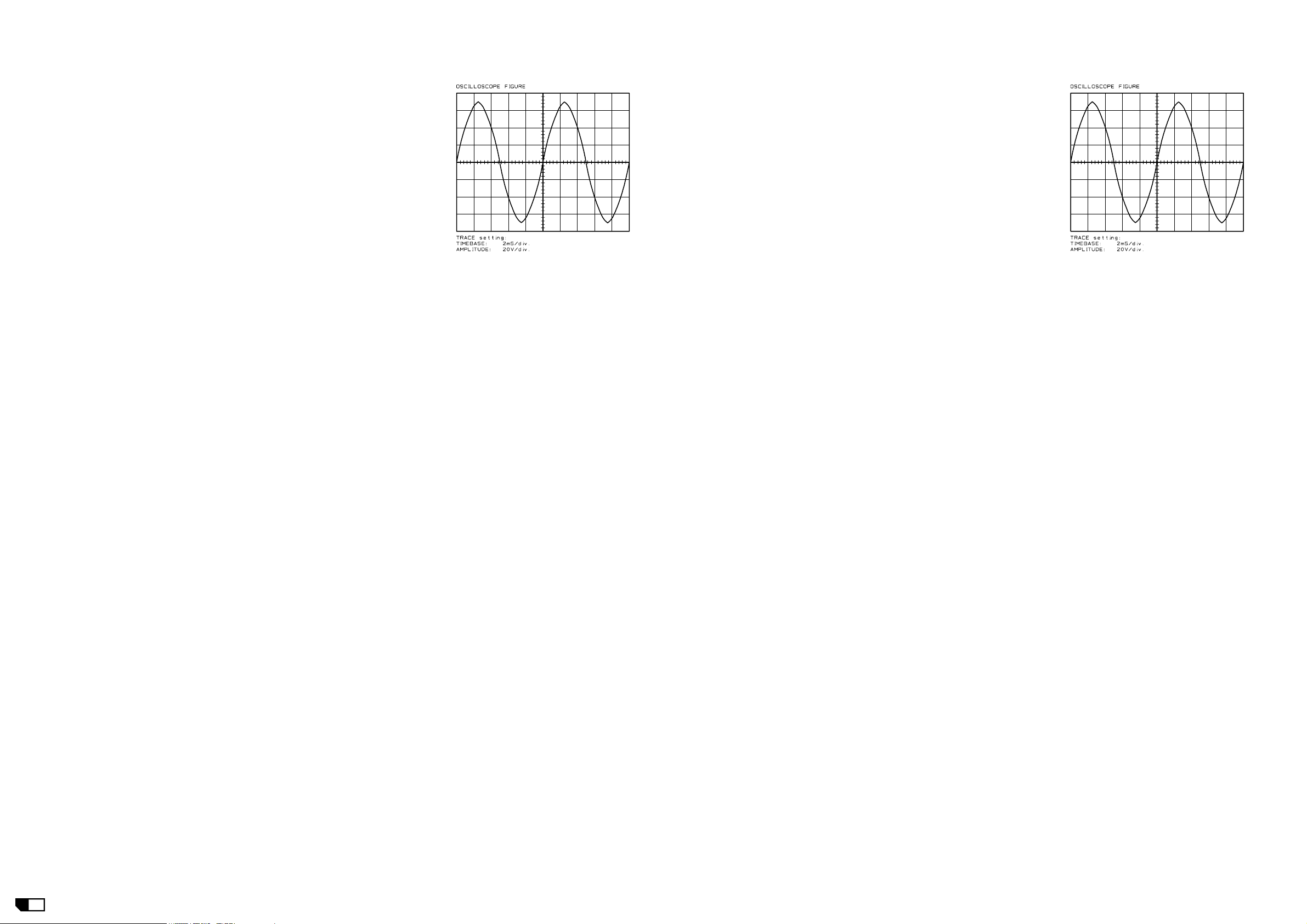
• Increasing the input
signal also the output
signal raise accordingly,
it must be symmetrical
without visible distortion
or oscillation as shown in
figure (note: the figure
is representative don`t
refer to the levels displayed). If there is a distortion read the section
ADVICES.
• When the input signal
exceeds -23dBm (10Vpp
on output) the SIGNAL
led lights and the fans
turn at their maximum
speed.
• Firstly you must check the channel without load, afterwards
you must repeat the check with the loads attached, the following
table reports the approx. maximum level obtainable with this
amp:
out level in level
no load 180Vpp +2.0dBm
1CH 8E 160Vpp +1.0dBm
1CH 4E 144Vpp +0.3dBm
2CH 8E 148Vpp +0.6dBm
2CH 4E 130Vpp -0.5dBm
CLIP LED ADJUSTMENTCLIP LED ADJUSTMENT
CLIP LED ADJUSTMENT
CLIP LED ADJUSTMENTCLIP LED ADJUSTMENT
• Check if the clip led lights at -6/-5dBm on input (~84Vpp on
output), if necessary adjust the trimmers W301/2 on display
board.
OFFSET ADJUSTMENTOFFSET ADJUSTMENT
OFFSET ADJUSTMENT
OFFSET ADJUSTMENTOFFSET ADJUSTMENT
• Set the input level at minimum (no signal), the output dc offset
voltage must be within ±20mV, if necessary adjust the VR101
trimmer (for each channel) to be within this threshold.
BIAS ADJUSTMENTBIAS ADJUSTMENT
BIAS ADJUSTMENT
BIAS ADJUSTMENTBIAS ADJUSTMENT
• No bias adjustment is necessary for this amplifier circuitry; in
any case the amplifier has the possibility to adjust it if necessary.
To check properly the bias proceed as follows:
• Using a sinusoidal signal (1KHz or more) and the 4E load
attached, wait till the heatsink temperature reaches about 60°c.
• Turn down the signal at the smallest intensity you can read on
your oscilloscope trace connected at the amplifier output.
• Zoom in the crossing region using the amplitude, timebase and
trigger controls of your oscilloscope. If you see a distortion, try
to eliminate it adjusting the VR102 trimmer.
• Finally, set the input level at minimum and verify with the
multimeter attached across an emitter resistance (p.e. R132)
that the dc voltage doesn`t exceed 10mV.
ADVICESADVICES
ADVICES
ADVICESADVICES
• If you have determinate that the problem is a short on a rail,
you must check the output transistors.
• To determine which transistor devices are bad, use a soldering
iron to lift one leg of each emitter pin and measure the resistance
across emitter and collector of each device. Unsolder and lift one
leg of each base pin and check the base-collector resistance.
Replace any device that measure as a short.
• If all the transistors are OK, unsolder and lift one leg of each
diode and check them.
• Check the circuit board for open foil traces.
• Use the Multimeter to check the resistors, particularly the base
and emitter resistors of damaged transistor.
• If the input sinewave appears to be distorted during the
negative cycle, you can assume that the problem is located
somewhere in the circuitry of the positive rail.
• If the positive cycle appears distorted, you can assume that
the problem is in the circuitry of the negative rail.
• The dc voltages printed on the schematics are measured with
the amplifier in steady state without input signal and nominal
mains voltage supply, it can be useful to localize a damage.
PROCON1500 - Test procedures andPROCON1500 - Test procedures and
PROCON1500 - Test procedures and
PROCON1500 - Test procedures andPROCON1500 - Test procedures and
adjustmentsadjustments
adjustments
adjustmentsadjustments
PRECAUTIONPRECAUTION
PRECAUTION
PRECAUTIONPRECAUTION
• To prevent short circuit during any test, the oscilloscope must
be EARTH INSULATED, this occurs because some test require to
connect its probe to the amplifier output, non-compliance may
cause damages to oscilloscope inputs circuitry.
• Before removing or installing any modules and connectors,
disconnect the amplifier from AC MAINS and measure the DC
supply voltages across each of the power supply capacitors. If
your measurement on any of the caps is greater than 10Vdc,
connect a 100E 100W resistor across the applicable caps to
discharge them for your safety. Remember to remove the
discharge resistor immediately after discharging caps. Do not
power up the amplifier with the discharge resistor connected.
• Do not check the amplifier with the speakers connected use the
appropriate load resistors only.
• BE CAREFUL increasing the Variac you must not exceed the
nominal mains voltage plus its tolerance (see specifications) any
upper voltage can be cause of damage.
VISUAL CHECKVISUAL CHECK
VISUAL CHECK
VISUAL CHECKVISUAL CHECK
• Use compressed air to clear dust in the amplifier chassis.
• Before proceed to supply the amplifier check visually the
internal assembly, if appears an evident damage find the most
possible reasons that cause it.
• Check the wiring cables for possible interruptions or shorts.
• If the damage has burnt a printed circuit board don’t try to
repair it, replace with a new one.
TESTING GEARTESTING GEAR
TESTING GEAR
TESTING GEARTESTING GEAR
• Audio Generator
• Dual Trace Oscilloscope
• Digital Multimeter
• 4E 800W, 8E 500W, 100E 100W resistors
• Variac
• Digital Thermometer (not indispensable)
SETUPSETUP
SETUP
SETUPSETUP
• Connect the Variac between the Mains and the amplifier and
set it at zero voltage.
• Turn full counter-clockwise the LEVEL potentiometers.
• Connect the audio generator to the channel inputs and set it to
1KHz 775mVrms (0dBm) sinusoidal signal.
• Connect the two scope traces to the amplifier outputs, before
the relay, and set them in DC at 20V/div. 2mS/div.
SUPPLY CHECKSUPPLY CHECK
SUPPLY CHECK
SUPPLY CHECKSUPPLY CHECK
• Verify with the Multimeter the insulation between the heatsinks
and all transistor collectors mounted on them; placing the
multimeter tips between the screw heads and the collector pins
you can exclude an erroneus reading due to the insulation of the
heatsink anodization.
• Verify with the Multimeter the NTC (RT1) and R1 paralleled
resistor value, it must be about 7KE (at 25°c).
• Turn on the Amplifier.
• Remove the transformer secondary fuses, set the Variac to the
nominal mains voltage, check with the Multimeter the AC supply
voltages:
F1-F2 = 28±2Vac.
F3-gnd and F4-gnd = 71±8Vac.
• Re-set the Variac at zero voltage, turn off the amplifier and put
the fuses back on its holders.
• Set up the Variac slowly monitoring the oscilloscope screen, it
should display no signal; if you notice a DC voltage or a
protection trips check the amplifier as suggested in the ADVICES.
• As soon as the +12VF supply circuit reaches its nominal value,
all cooling fans run at their minimum and the speaker output
relais (J201-202) switch.
• When the Variac ac voltage reaches the nominal voltage verify
the DC supplies as follow:
+VCC = +100±8Vdc
-VCC = -100±8Vdc
U201 pin 8 = +12±0.5Vdc
U201 pin 4 = -12±0.5Vdc
U202 pin 3 = +12±0.5Vdc
• If one or more voltages don’t correspond, check the rectifiers,
capacitors and transformers disconnecting them from circuitry.
CHANNEL CHECKCHANNEL CHECK
CHANNEL CHECK
CHANNEL CHECKCHANNEL CHECK
• Be sure you have disconnected the load resistor.
• Increasing the input
signal also the output
signal raise accordingly,
it must be symmetrical
without visible distortion
or oscillation as shown in
figure (note: the figure
is representative don`t
refer to the levels displayed). If there is a distortion read the section
ADVICES.
• When the input signal
exceeds -24dBm (10Vpp
on output) the SIGNAL
led lights and the fans
turn at their maximum
speed.
• Firstly you must check the channel without load, afterwards
you must repeat the check with the loads attached, the following
table reports the approx. maximum level obtainable with this
amp:
out level in level
no load 190Vpp +1.8dBm
1CH 8E 170Vpp +0.8dBm
1CH 4E 158Vpp +0.2dBm
2CH 8E 159Vpp +0.3dBm
2CH 4E 142Vpp -0.8dBm
CLIP LED ADJUSTMENTCLIP LED ADJUSTMENT
CLIP LED ADJUSTMENT
CLIP LED ADJUSTMENTCLIP LED ADJUSTMENT
• Check if the clip led lights at -6/-5dBm on input (~88Vpp on
output), if necessary adjust the trimmers W301/2 on display
board.
OFFSET ADJUSTMENTOFFSET ADJUSTMENT
OFFSET ADJUSTMENT
OFFSET ADJUSTMENTOFFSET ADJUSTMENT
• Set the input level at minimum (no signal), the output dc offset
voltage must be within ±20mV, if necessary adjust the VR101
trimmer (for each channel) to be within this threshold.
BIAS ADJUSTMENTBIAS ADJUSTMENT
BIAS ADJUSTMENT
BIAS ADJUSTMENTBIAS ADJUSTMENT
• No bias adjustment is necessary for this amplifier circuitry; in
any case the amplifier has the possibility to adjust it if necessary.
To check properly the bias proceed as follows:
• Using a sinusoidal signal (1KHz or more) and the 4E load
attached, wait till the heatsink temperature reaches about 60°c.
• Turn down the signal at the smallest intensity you can read on
your oscilloscope trace connected at the amplifier output.
• Zoom in the crossing region using the amplitude, timebase and
trigger controls of your oscilloscope. If you see a distortion, try
to eliminate it adjusting the VR102 trimmer.
• Finally, set the input level at minimum and verify with the
multimeter attached across an emitter resistance (p.e. R132)
that the dc voltage doesn`t exceed 10mV.
ADVICESADVICES
ADVICES
ADVICESADVICES
• If you have determinate that the problem is a short on a rail,
you must check the output transistors.
• To determine which transistor devices are bad, use a soldering
iron to lift one leg of each emitter pin and measure the resistance
across emitter and collector of each device. Unsolder and lift one
leg of each base pin and check the base-collector resistance.
Replace any device that measure as a short.
• If all the transistors are OK, unsolder and lift one leg of each
diode and check them.
• Check the circuit board for open foil traces.
• Use the Multimeter to check the resistors, particularly the base
and emitter resistors of damaged transistor.
• If the input sinewave appears to be distorted during the
negative cycle, you can assume that the problem is located
somewhere in the circuitry of the positive rail.
• If the positive cycle appears distorted, you can assume that
the problem is in the circuitry of the negative rail.
• The dc voltages printed on the schematics are measured with
the amplifier in steady state without input signal and nominal
mains voltage supply, it can be useful to localize a damage.
44
4
44
Page 5
55
5
55
Page 6
66
6
66
Page 7
77
7
77
Page 8
88
8
88
Page 9
99
9
99
Page 10
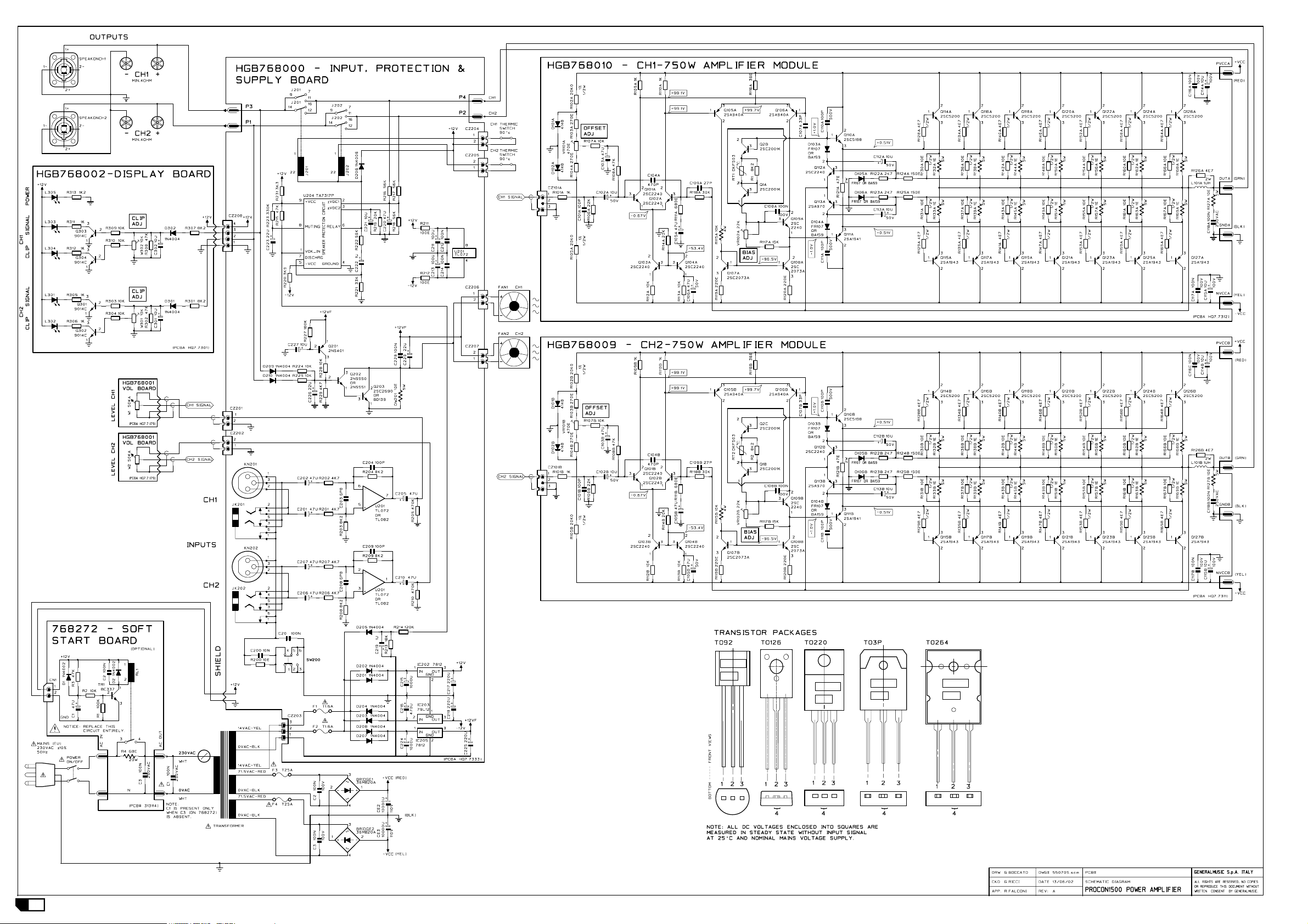
1010
10
1010
Page 11

Spare Part ListSpare Part List
Spare Part List
Spare Part ListSpare Part List
Legend
EU = Europe Version
US = US Version
code description
PROCON 400/750PROCON 400/750
PROCON 400/750
PROCON 400/750PROCON 400/750
130285 Mains Cable (EU)
110291 16A 250Vac Bipolar Power Switch
020493 100n 250Vac MKP EMI Capacitor “Siemens”
HGB238001 Transformer 230Vac 550W (EU) (Procon 400)
HGB238002 Transformer 230Vac 900W (EU) (Procon 750)
080608 36MB20A 35A 200V Rectifier Diode Bridge
HGB030000 10000u 80V -10+50% V Electrolytic Capacitor VT
110038 T16A Fuse 6.3x32mm (EU)(US) (Procon 750)
110027 T10A Fuse 6.3x32mm (EU)(US) (Procon 400)
141200 Speakon Socket (NL4MP Neutrik)
HGB347000 Volume Knob
HGB140000 Dual Red/Blk Binding Post
HGB110300 12Vdc 0.25A 80x25mm Fan
110360 Fan Grid 80mm
HGB768012 * I
HGB768011 *
HGB140001 * 2sw 2pos H Slider Switch
HGB140002 * Hor Female XLR Socket
HGB140003 * Jack Horizontal S-F Socket
HGB110301 * Relay 12V / 2 Switch 10A 250Vac
HGB100000 * TA7317P Speaker Protection Circuit
HGB090009 * 2SA965-O TO92 Pnp Transistor
HGB090007 * 2SC2235-O TO92 Npn Transistor
HGB090000 * 2SC2240GR TO92 LN Npn Transistor
110011 * T1A Fuse 5x20mm (EU)
100061 * TL072 Dual J-Fet Operational Amplifier
100045 * 7812 +12V 1A Voltage Regulator
090200 * 2N5550/1 TO92 Npn Transistor
080158 * 1N4004 1A 400V Rectifier Diode
080103 * 1N4148 100mA 75V Signal Diode
060521 * 2K2 2W 10% Resistor
060253 * 10E 5W 10% Wire Resistor
050691 * 470K 1/4W 5% Resistor
050651 * 220K 1/4W 5% Resistor
050571 * 47K 1/4W 5% Resistor
050561 * 39K 1/4W 5% Resistor
050541 * 27K 1/4W 5% Resistor
050531 * 22K 1/4W 5% Resistor
050511 * 15K 1/4W 5% Resistor
050491 * 10K 1/4W 5% Resistor
050471 * 6K8 1/4W 5% Resistor
050401 * 1K8 1/4W 5% Resistor
050391 * 1K5 1/4W 5% Resistor
050381 * 1K2 1/4W 5% Resistor
050371 * 1K 1/4W 5% Resistor
050301 * 270E 1/4W 5% Resistor
050291 * 220E 1/4W 5% Resistor
050231 * 68E 1/4W 5% Resistor
030721 * 1000u 25V 20% Vert Electrolytic Capacitor
030650 * 470u 25V 20% Vert Electrolytic Capacitor
030565 * 220u 25V 20% Vert Electrolytic Capacitor
030485 * 100u 25V 20% Vert Electrolytic Capacitor
030403 * 47u 25V 20% Vert Electrolytic Capacitor
030324 * 22u 50V 20% Vert Electrolytic Capacitor
030245 * 10u 50V 20% Vert Electrolytic Capacitor
021024 * 100n 63V 10% MKT Polyester Capacitor
010595 * 100n 50V -20+80% Ceramic Cap. Multilayer
010443 * 680p 50V 10% CL2 Ceramic Capacitor
010335 * 100p 500V 10% CL2 Ceramic Capacitor
010200 * 6p8 50V 10% CL2 Ceramic Capacitor
HGB768001 Volume Board (PCBA HQ7.7.179)
HGB075000 * 50KA RK16 Hor Rotary Potentiometer K15 40CLK
HGB768002 Display Board (PCBA HQ7.7301)
MDL090000 * 9014C Npn TO92 Ebc 50V 0,15A
080158 * 1N4004 1A 400V Rectifier Diode
070181 * 10K 20% Horizontal Linear Trimmer
050571 * 47K 1/4W 5% Resistor
050491 * 10K 1/4W 5% Resistor
050381 * 1K2 1/4W 5% Resistor
Assembly
Input, Protection & Supply BoardInput, Protection & Supply Board
Input, Protection & Supply Board
Input, Protection & Supply BoardInput, Protection & Supply Board
nput, Protection & Supply Board (PCBA HQ7.7332)(Procon750)
Input, Protection & Supply Board (PCBA HQ7.7302)(Procon400)
Volume BoardVolume Board
Volume Board
Volume BoardVolume Board
Display BoardDisplay Board
Display Board
Display BoardDisplay Board
050371 * 1K 1/4W 5% Resistor
042634 * 20K0 1/4W 1% Metalized Film Resistor
030245 * 10u 50V 20% Vert Electrolytic Capacitor
Amplifier ModuleAmplifier Module
Amplifier Module
Amplifier ModuleAmplifier Module
HGB768014 375+375W Amplifier Module (PCBA HQ7.7308)
HGB768013 200+200W Amplifier Module (PCBA HQ7.7307)
090201 * 2N5400/1 TO92 Pnp Transistor
090200 * 2N5550/1 TO92 Npn Transistor
HGB090008 * 2SC2690 TO126 Npn Transistor
HGB090010 * 2SA1220 TO126 Pnp Transistor
HGB090014 * 2SA1943 TO264 Pnp Transistor
HGB090013 * 2SC5200 TO264 Npn Transistor
HGB090006 * 2SA1941 TO3P/TO218 Pnp Transistor
HGB090005 * 2SC5198 TO3P/TO218 Npn Transistor
HGB090004 * 2SA970GR TO92 LN Pnp Transistor
HGB090001 * 2SC2001K TO92 Npn Transistor
HGB090000 * 2SC2240GR TO92 LN Npn Transistor
HGB080800 * Ntc type DKF503 (Thermometrics)
080158 * 1N4004 1A 400V Rectifier Diode
080103 * 1N4148 100mA 75V Signal Diode
060253 * 10E 5W 10% Wire Resistor
060210 * 4E7 2W 10% Resistor
050611 * 100K 1/4W 5% Resistor
050491 * 10K 1/4W 5% Resistor
050461 * 5K6 1/4W 5% Resistor
050301 * 270E 1/4W 5% Resistor
050131 * 10E 1/4W 5% Resistor
050091 * 4E7 1/4W 5% Resistor
030324 * 22u 50V 20% Vert Electrolytic Capacitor
030245 * 10u 50V 20% Vert Electrolytic Capacitor
030245 * 10u 50V 20% Vert Electrolytic Capacitor
020481 * 100n 100V10% MKT Polyester Capacitor
010595 * 100n 50V -20+80% Ceramic Cap. Multilayer
010335 * 100p 500V 10% CL2 Ceramic Capacitor
PROCON 950/1100/1250/1500PROCON 950/1100/1250/1500
PROCON 950/1100/1250/1500
PROCON 950/1100/1250/1500PROCON 950/1100/1250/1500
130285 Mains Cable (EU)
110291 16A 250Vac Bipolar Power Switch
020493 100n 250Vac MKP EMI Capacitor “Siemens”
HGB238003 Transformer 230Vac 1100W (EU) (Procon 950)
HGB238004 Transformer 230Vac 1200W (EU) (Procon 1100)
HGB238005 Transformer 230Vac 1600W (EU) (Procon 1250)
HGB238006 Transformer 230Vac 1900W (EU) (Procon 1500)
080608 36MB20A 35A 200V Rectifier Diode Bridge
HGB030002 10000u 110V -10+50% V Electrolytic Capacitor VT (Procon1250/1500)
HGB030001 10000u 100V -10+50% V Electrolytic Capacitor VT (Procon950/1100)
110063 T25A Fuse 6.3x32mm (EU)(US) (Procon 1500)
110062 T20A Fuse 6.3x32mm (EU)(US) (Procon 1250)
110038 T16A Fuse 6.3x32mm (EU)(US) (Procon 950/1100)
141200 Speakon Socket (NL4MP Neutrik)
HGB347000 Volume Knob
HGB140000 Dual Red/Blk Binding Post
HGB110300 12Vdc 0.25A 80x25mm Fan (Procon 950/1100)
HGB110302 12Vdc 0.45A 80x25mm Fan (Procon 1250/1500)
110360 Fan Grid 80mm
768272 Soft Start Board (Pcb#313114) (NL version only)
140917 * 2 Contacts Vert Male Connector
120857 * 6.3mm Vertical Male Faston for Pcb
110324 * Relay NO 1 SC.12V 20A R=160E
090152 * BC337 TO92 Npn Transistor
080156 * 1N4002 1A 100V Rectifier Diode
080103 * 1N4148 100mA 75V Signal Diode
061341 * 68E 20W 5% Wire Resistor
052060 * 100K 1/8w 5% Resistor
052056 * 47K 1/8w 5% Resistor
052048 * 10K 1/8w 5% Resistor
030403 * 47u 25V 20% Vert Electrolytic Capacitor
020493 * 100n 250Vac MKP EMI Capacitor “Siemens”
010595 * 100n 50V -20+80% Ceramic Cap. Multilayer
HGB768000 Input, Protection & Supply Board (PCBA HQ7.7333)
HGB140001 * 2sw 2pos H Slider Switch
HGB140002 * Hor Female XLR Socket
HGB140003 * Jack Horizontal S-F Socket
HGB110301 * Relay 12V / 2 Switch 10A 250Vac
HGB100000 * TA7317P Speaker Protection Circuit
HGB090008 * 2SC2690 TO126 Npn Transistor
110012 * T1.6A Fuse 5x20mm (EU) (Procon1100/1250/1500)
110011 * T1A Fuse 5x20mm (EU) (Procon950)
Assembly
Soft Start BoardSoft Start Board
Soft Start Board
Soft Start BoardSoft Start Board
Input, Protection & Supply BoardInput, Protection & Supply Board
Input, Protection & Supply Board
Input, Protection & Supply BoardInput, Protection & Supply Board
(Procon950/1100/1250/1500)
100061 * TL072 Dual J-Fet Operational Amplifier
100045 * 7812 +12V 1A Voltage Regulator
100043 * 7912 -12V 1A Voltage Regulator
090201 * 2N5400/1 TO92 Pnp Transistor
090200 * 2N5550/1 TO92 Npn Transistor
080158 * 1N4004 1A 400V Rectifier Diode
060253 * 10E 5W 10% Wire Resistor
050691 * 470K 1/4W 5% Resistor
050671 * 330K 1/4W 5% Resistor
050641 * 180K 1/4W 5% Resistor
050621 * 120K 1/4W 5% Resistor
050581 * 56K 1/4W 5% Resistor
050571 * 47K 1/4W 5% Resistor
050551 * 33K 1/4W 5% Resistor
050521 * 18K 1/4W 5% Resistor
050491 * 10K 1/4W 5% Resistor
050481 * 8K2 1/4W 5% Resistor
050451 * 4K7 1/4W 5% Resistor
050441 * 3K9 1/4W 5% Resistor
050431 * 3K3 1/4W 5% Resistor
050251 * 100E 1/4W 5% Resistor
050131 * 10E 1/4W 5% Resistor
042634 * 20K0 1/4W 1% Metalized Film Resistor
030721 * 1000u 25V 20% Vert Electrolytic Capacitor
030650 * 470u 25V 20% Vert Electrolytic Capacitor
030565 * 220u 25V 20% Vert Electrolytic Capacitor
030485 * 100u 25V 20% Vert Electrolytic Capacitor
030403 * 47u 25V 20% Vert Electrolytic Capacitor
030324 * 22u 50V 20% Vert Electrolytic Capacitor
030245 * 10u 50V 20% Vert Electrolytic Capacitor
030005 * 1u 50V 20% Vert Electrolytic Capacitor
021024 * 100n 63V 10% MKT Polyester Capacitor
021012 * 10n 63V 10% MKT Polyester Capacitor
010595 * 100n 50V -20+80% Ceramic Cap. Multilayer
010200 * 6p8 50V 10% CL2 Ceramic Capacitor
Volume BoardVolume Board
Volume Board
Volume BoardVolume Board
HGB768001 Volume Board (PCBA HQ7.7.179)
HGB075000 * 50KA RK16 Hor Rotary Potentiometer K15 40CLK
Display BoardDisplay Board
Display Board
Display BoardDisplay Board
HGB768002 Display Board (PCBA HQ7.7301)
MDL090000 * 9014C Npn TO92 Ebc 50V 0,15A
080158 * 1N4004 1A 400V Rectifier Diode
070181 * 10K 20% Horizontal Linear Trimmer
050571 * 47K 1/4W 5% Resistor
050491 * 10K 1/4W 5% Resistor
050381 * 1K2 1/4W 5% Resistor
050371 * 1K 1/4W 5% Resistor
050481 * 8K2 1/4W 5% Resistor
042634 * 20K0 1/4W 1% Metalized Film Resistor
030245 * 10u 50V 20% Vert Electrolytic Capacitor
Power Amplifier ModulePower Amplifier Module
Power Amplifier Module
Power Amplifier ModulePower Amplifier Module
HGB768010 CH1-750W Amplifier Module (PCBA HQ7.7312)
HGB768009 CH2-750W Amplifier Module (PCBA HQ7.7311)
HGB768008 CH1-625W Amplifier Module (PCBA HQ7.7198)
HGB768007 CH2-625W Amplifier Module (PCBA HQ7.7198)
HGB768006 CH1-550W Amplifier Module (PCBA HQ7.7198)
HGB768005 CH2-550W Amplifier Module (PCBA HQ7.7198)
HGB768004 CH1-475W Amplifier Module (PCBA HQ7.7314)
HGB768003 CH2-475W Amplifier Module (PCBA HQ7.7314)
HGB090014 * 2SA1943 TO264 Pnp Transistor
HGB090013 * 2SC5200 TO264 Npn Transistor
HGB090006 * 2SA1941 TO3P/TO218 Pnp Transistor
HGB090005 * 2SC5198 TO3P/TO218 Npn Transistor
HGB090004 * 2SA970GR TO92 LN Pnp Transistor
HGB090003 * 2SA940A TO220F Pnp Transistor
HGB090002 * 2SC2073A TO220F Npn Transistor
HGB090001 * 2SC2001K TO92 Npn Transistor
HGB090000 * 2SC2240GR TO92 LN Npn Transistor
HGB080800 * Ntc type DKF503 (Thermometrics)
HGB080000 * FR107 OR BA159 Fast Rec Diode 1A 1000V 500ns DO41
HGB061000 * 10K 4W 10% Resistor
230557 * 1uH Horizontal Coil For Amplifier
120857 * 6.3mm Vertical Male Faston for Pcb
080103 * 1N4148 100mA 75V Signal Diode
070201 * 22K 20% Horizontal Linear Trimmer
070106 * 470E 20% Horizontal Linear Trimmer
060336 * 47E 2W 10% Resistor
060253 * 10E 5W 10% Wire Resistor
060210 * 4E7 2W 10% Resistor
060151 * 1E 5W 10% Wire Resistor
052047 * 8K2 1/8w 5% Resistor
050571 * 47K 1/4W 5% Resistor
050541 * 27K 1/4W 5% Resistor
050531 * 22K 1/4W 5% Resistor
050511 * 15K 1/4W 5% Resistor
050491 * 10K 1/4W 5% Resistor
050421 * 2K7 1/4W 5% Resistor
050371 * 1K 1/4W 5% Resistor
050351 * 680E 1/4W 5% Resistor
050301 * 270E 1/4W 5% Resistor
050291 * 220E 1/4W 5% Resistor
050271 * 150E 1/4W 5% Resistor
042634 * 20K0 1/4W 1% Metalized Film Resistor
040134 * 10E 1/2W 5% Resistor
040091 * 4E7 1/2W 5% Resistor
030410 * 47u 50V 20% Vert Electrolytic Capacitor
030403 * 47u 25V 20% Vert Electrolytic Capacitor
030245 * 10u 50V 20% Vert Electrolytic Capacitor
020481 * 100n 100V10% MKT Polyester Capacitor
010426 * 470p 50V 10% CL2 Ceramic Capacitor
010345 * 100p 50V 10% CL2 Ceramic Capacitor
010335 * 100p 500V 10% CL2 Ceramic Capacitor
010293 * 33p 50V 10% CL2 Ceramic Capacitor
010282 * 27p 50V 10% CL2 Ceramic Capacitor
Note:Note:
Note:
Note:Note:
- All dimensions are in mm unless otherwise specified.
- Each spare part is single quantity unless otherwise specified.
- Asterisk prefix explanation:
Omitted = First level spare part.
One asterisk = Second level, part of previous listed first level part.
Two asterisk = Third level, part of previous listed second level part.
Three asterisk = ............
- Any request for not above mentioned part must encompass specific description
including:
1) Model name,
2) Section name,
3) Module code,
4) Reference name,
5) Quantity number.
1111
11
1111
 Loading...