

Page 1

Page 2
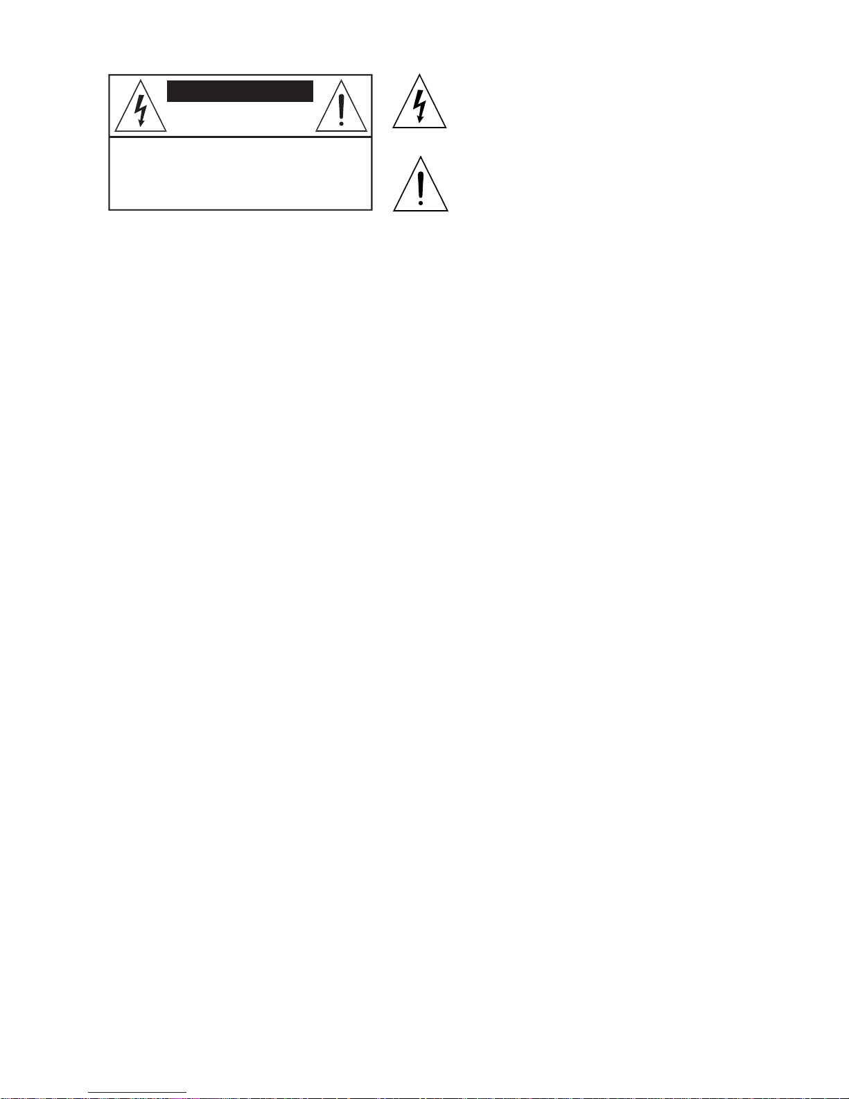
CAUTION
RISK OF ELETRIC SHOCK
DO NOT OPEN
CAUTION: TO REDUCE THE RISK OF ELETRIC
SHOCK DO NOT REMOVE COVER (OR BACK)
NO USER-SERVICEABLE PARTS INSIDE
REFER SERVICING TO QUALIFIED PERSONNEL
IMPORTANT SAFETY INSTRUCTIONS
INSTRUCTIONS PERTAINING TO A RISK OF FIRE, ELECTRIC SHOCK OR INJURY TO PERSONS
WARNING - When using electric products, basic precautions should always be followed, including
the following:
1. Read all the SAFETY INSTRUCTIONS before using the product.
2. To reduce the risk of injury, close supervision is necessary when the product is used near children.
3. Do not use this product near water - for example, near a bathtub, washbowl, kitchen sink, in a wet
basement or near a swimming poor or the like.
4. This product in combination with headphones or an amplifier, may be capable of producing sound
levels that could cause permanent hearing loss. Do not operate for a long period of time at high volume
level or at a level that is uncomfortable. If you experience any hearing loss or ringing in the ears, you
should consult an audiologist.
5. This product should be located so that its location or position does not interfere with its proper
ventilation.
6. This product should be located away from heat sources such as radiators, heat registers or other
products that produce heat.
7. The product should be connected to a power supply only of the type described on the operating
instructions or as marked on the product.
8. This product may be equipped with a polarized line plug (one blade wider than the other). This is
a safety feature. If you are unable to insert the plug into the outlet, contact an electrician to replace
your obsolete outlet. Do not defeat the safety purpose of the plug.
9. The power-supply cord of the product should be unplugged from the outlet when left unused for a
long period of time. When unplugging the power-supply cord, do not pull on the cord, but grasp it by
the plug.
10. Care should be taken so that object do not fall and liquid are not spilled into the enclosure through
openings.
11. The product should be serviced by qualified service personnel when:
A. The power-supply cord or the plug has been damaged; or
B. Objects have fallen, or liquid has been spilled into the product; or
C. The product has been exposed to rain; or
D. The product does not appear to operate normally or exhibits a marked change in performance; or
E. The product has been dropped or the enclosure damaged.
12. Do not attempt to service the product beyond that described in the user-maintenance instructions.
All other servicing should be referred to qualified service personnel.
13. WARNING - Do not place objects on the product's power cord or place it in a position where
anyone could trip over, walk on or roll anything over it. Do not allow the product to rest on or to be
installed over power cords of any type. Improper installations of this type create the possibility of fire
hazard and/or personal injury.
SAVE THESE INSTRUCTIONS
The lightning flash with arrowhead symbol within an equilateral
triangle is intended to alert the user to the presence of
uninsulated "dangerous voltage" within the product's
enclosure, that may be of sufficient magnitude to constitute a
risk of electric shock to persons.
The exclamation point within an equilateral triangle is intended
to alert the user to the presence of important operating and
maintenance (servicing) instructions in the literature
accompanying the appliance.
Page 3
1
Introduction
Introduction
Introduction. . . . . . . . . . . . . . . . . . . . . . . . . . . . . . . . . . . . . . . . . . . . . . . . . . 2
The technology . . . . . . . . . . . . . . . . . . . . . . . . . . . . . . . . . . . . . . . . . . . . . . . . 2
Active Power Factor Correction . . . . . . . . . . . . . . . . . . . . . . . . . . . . . . . . . . . 2
Extremely high constant efficiency. . . . . . . . . . . . . . . . . . . . . . . . . . . . . . . . . 3
Higher power, lower weight, smaller dimensions. . . . . . . . . . . . . . . . . . . . . . 3
Total control . . . . . . . . . . . . . . . . . . . . . . . . . . . . . . . . . . . . . . . . . . . . . . . . . . 3
The sound. . . . . . . . . . . . . . . . . . . . . . . . . . . . . . . . . . . . . . . . . . . . . . . . . . . . 3
Protection features . . . . . . . . . . . . . . . . . . . . . . . . . . . . . . . . . . . . . . . . . . . . . 4
Rules for installation and use . . . . . . . . . . . . . . . . . . . . . . . . . . . . . . . . . . . 5
Functions & Controls. . . . . . . . . . . . . . . . . . . . . . . . . . . . . . . . . . . . . . . . . . 7
POWER ON/OFF . . . . . . . . . . . . . . . . . . . . . . . . . . . . . . . . . . . . . . . . . . . 7
INPUT ATTENUATORS. . . . . . . . . . . . . . . . . . . . . . . . . . . . . . . . . . . . . . 7
METERs . . . . . . . . . . . . . . . . . . . . . . . . . . . . . . . . . . . . . . . . . . . . . . . . . . 7
PROTECT LEDs . . . . . . . . . . . . . . . . . . . . . . . . . . . . . . . . . . . . . . . . . . . 8
HI-FREQ LEDs . . . . . . . . . . . . . . . . . . . . . . . . . . . . . . . . . . . . . . . . . . . . . 8
SIGNAL LEDs . . . . . . . . . . . . . . . . . . . . . . . . . . . . . . . . . . . . . . . . . . . . . 8
TEMP LED . . . . . . . . . . . . . . . . . . . . . . . . . . . . . . . . . . . . . . . . . . . . . . . . 8
READY LED . . . . . . . . . . . . . . . . . . . . . . . . . . . . . . . . . . . . . . . . . . . . . . . 8
Connection panel . . . . . . . . . . . . . . . . . . . . . . . . . . . . . . . . . . . . . . . . . . . . . 9
INPUTS . . . . . . . . . . . . . . . . . . . . . . . . . . . . . . . . . . . . . . . . . . . . . . . . . . 9
LINK . . . . . . . . . . . . . . . . . . . . . . . . . . . . . . . . . . . . . . . . . . . . . . . . . . . . . 9
OUTPUTS . . . . . . . . . . . . . . . . . . . . . . . . . . . . . . . . . . . . . . . . . . . . . . . . 9
A.C. ~ . . . . . . . . . . . . . . . . . . . . . . . . . . . . . . . . . . . . . . . . . . . . . . . . . . . . 9
Connection examples . . . . . . . . . . . . . . . . . . . . . . . . . . . . . . . . . . . . . . . . 10
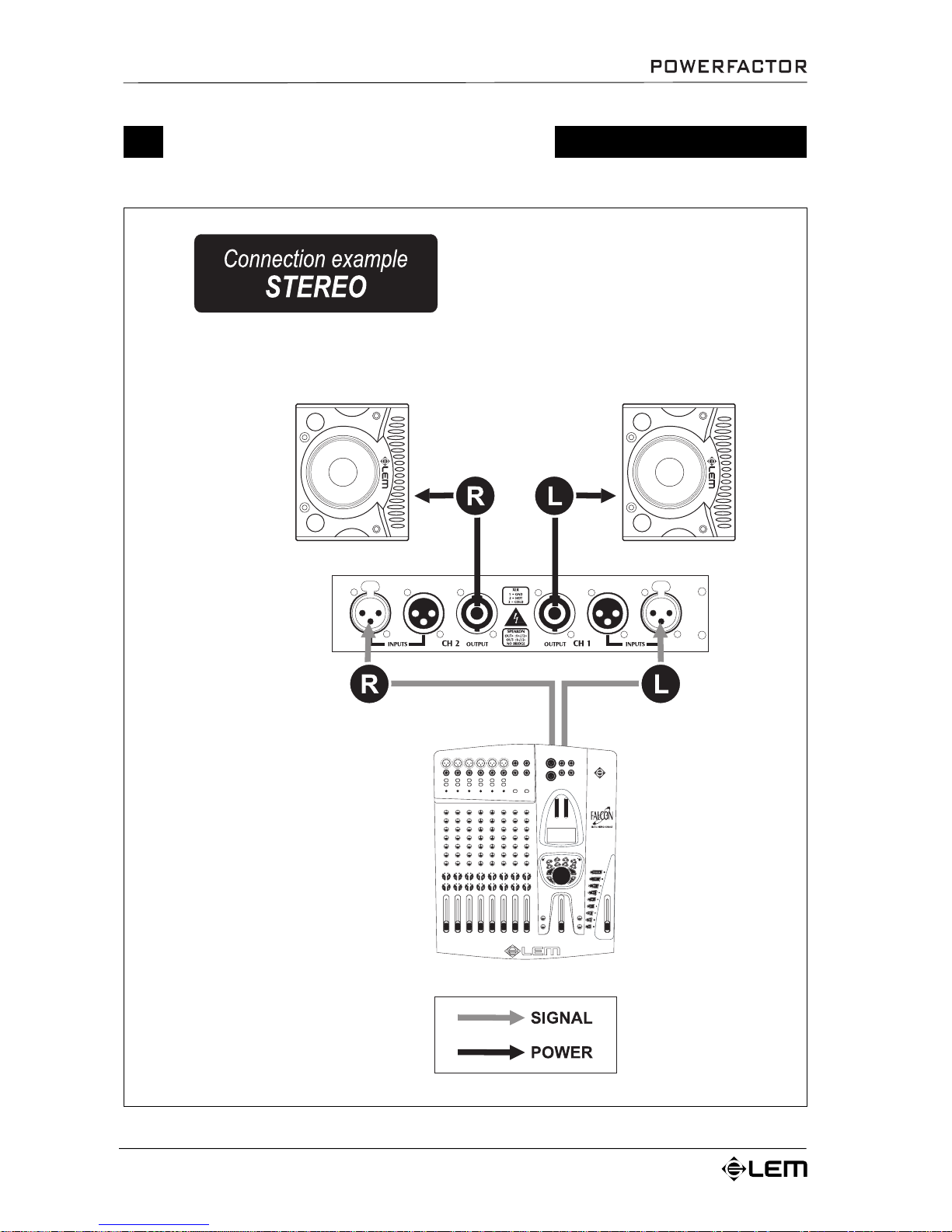
Stereo . . . . . . . . . . . . . . . . . . . . . . . . . . . . . . . . . . . . . . . . . . . . . . . . . . . . . . 10
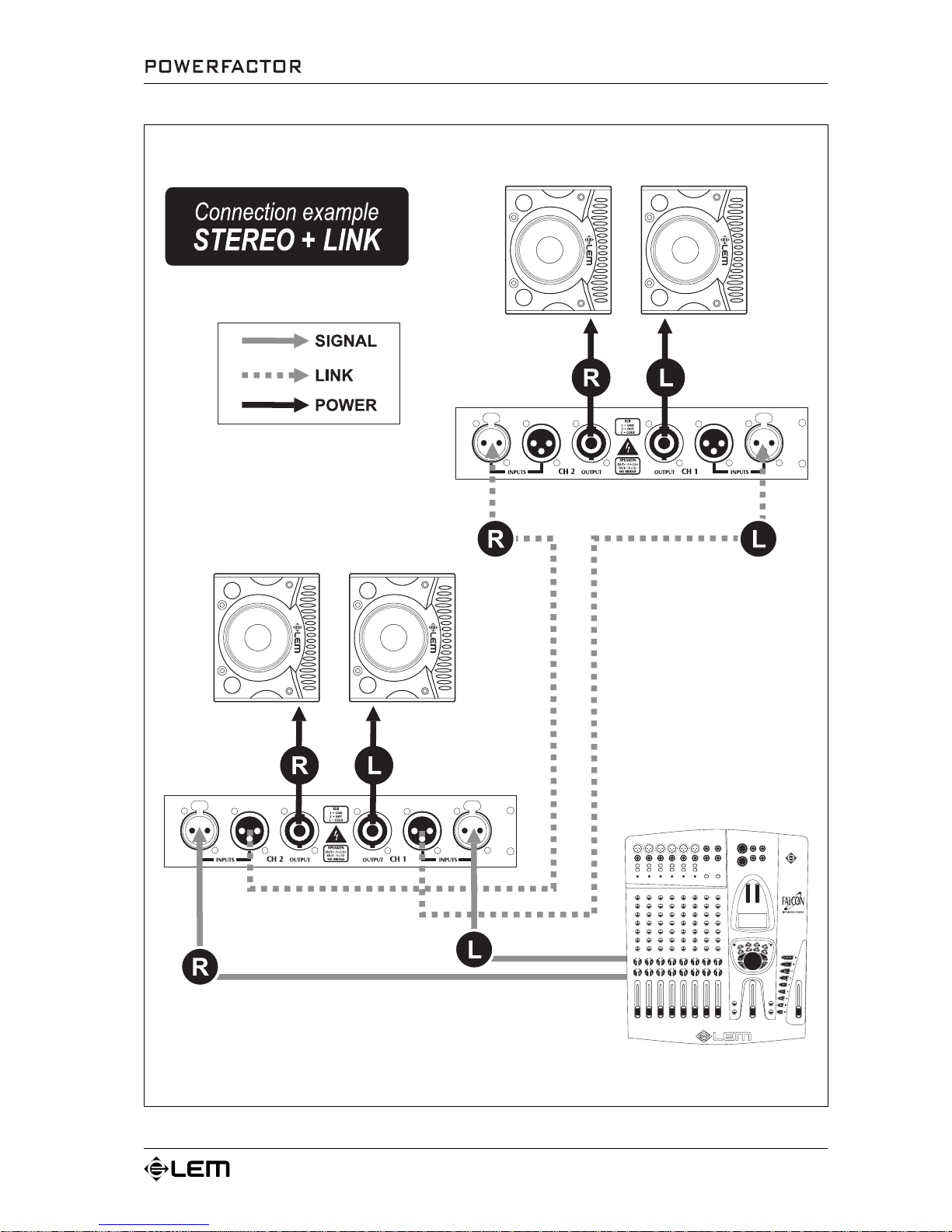
Stereo + Link . . . . . . . . . . . . . . . . . . . . . . . . . . . . . . . . . . . . . . . . . . . . . . . . 11
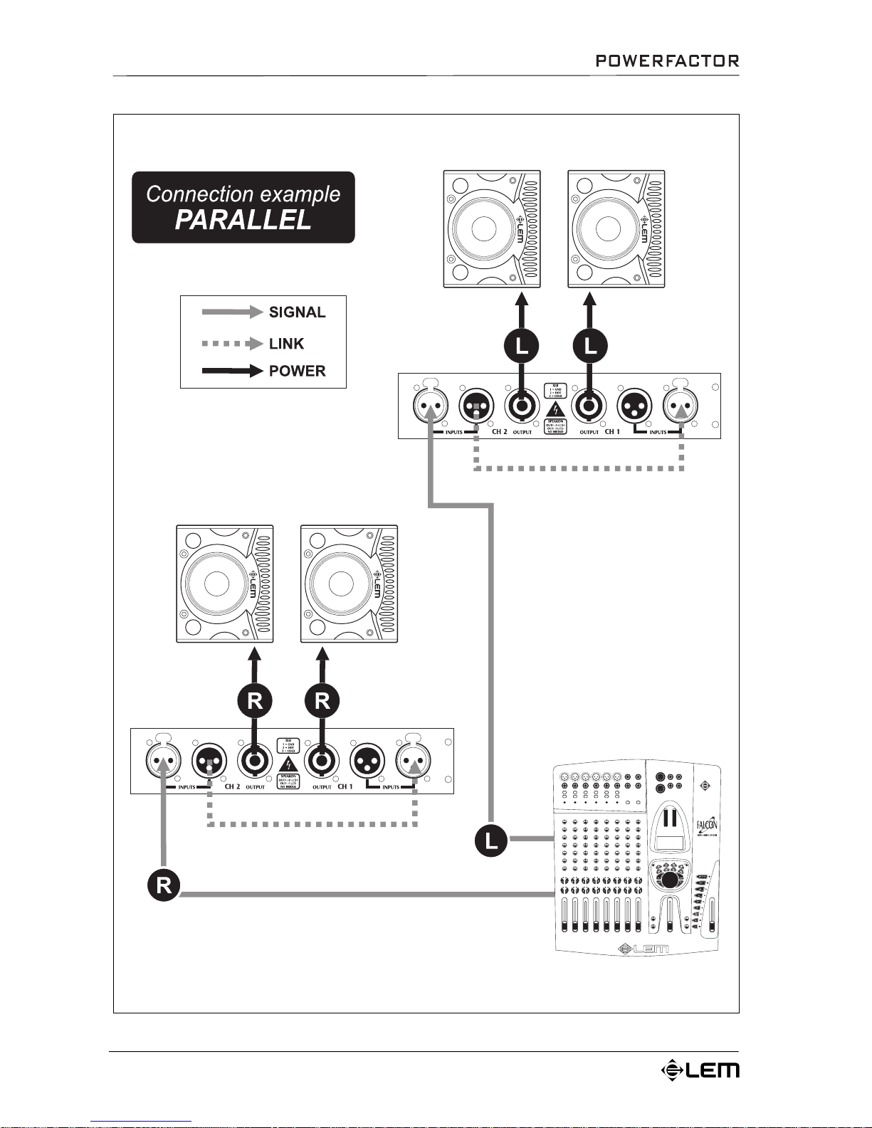
Parallel . . . . . . . . . . . . . . . . . . . . . . . . . . . . . . . . . . . . . . . . . . . . . . . . . . . . . 12
Connection cables . . . . . . . . . . . . . . . . . . . . . . . . . . . . . . . . . . . . . . . . . . . 13
Power cords . . . . . . . . . . . . . . . . . . . . . . . . . . . . . . . . . . . . . . . . . . . . . . . . . 13
Signal cables . . . . . . . . . . . . . . . . . . . . . . . . . . . . . . . . . . . . . . . . . . . . . . . . 14
Technical specifications . . . . . . . . . . . . . . . . . . . . . . . . . . . . . . . . . . . . . . 15
Diagrams . . . . . . . . . . . . . . . . . . . . . . . . . . . . . . . . . . . . . . . . . . . . . . . . . . . 16
POWERFACTOR 3 response curves . . . . . . . . . . . . . . . . . . . . . . . . . . . . . 16
POWERFACTOR 5 response curves . . . . . . . . . . . . . . . . . . . . . . . . . . . . . 18
Block diagram . . . . . . . . . . . . . . . . . . . . . . . . . . . . . . . . . . . . . . . . . . . . . . . . 20
Page 4
2
Congratulations for having chosen POWERFACTOR!
The POWERFACTOR Series is a new line of high-power amplifiers, designed and
manufactured for the most demanding professional uses: large concerts and tours; powerful sound
systems in clubs, theme parks and public events; quality sound reinforcement for theatres, cinemas and
conference halls; industrial applications, etc.
The technology
The POWERFACTOR Series represents a turning point in professional audio systems. In fact,
POWERFACTOR amplifiers have been designed and built using innovative DIGAM (DIGital
AMplifier) technology, a “dedicated” development of PWM (Pulse Width Modulation) technology,
used for over 30 years in very high efficiency power supply and stabilization systems.
Amplification stage with 250 kHz sampling rate, “full switching” output stage using very high
polarization current, a new concept in D/A power conversion systems and a series of other patented
devices are some of the features of this technology, which has enabled great results to be achieved:
ü Drastic reduction of heat dissipation
ü Radical reduction of dimensions and weight
ü Remarkable increase in power
ü Unbeatable constant efficiency values
ü Accurate tone definition
ü Great long-term sturdiness and reliability
Active Power Factor Correction
The “active power factor correction” is an exclusive function which contributes to distinguishing
POWERFACTOR amplifiers from other “switching” systems.
Simulating a purely resistive load on the mains power supply, this very important function enables to
ensure almost total stabilization of the power supply voltage of the output stage
no matter what the mains
voltage.
In practical terms, “active power factor correction” enables to leave the performance of the output stages
unvaried and minimize the reactive power and harmonic distortion introduced on the current absorbed.
For example, it’s therefore possible to ensure systems’ absolute stability and perfect dynamic capacity
even in medium/large sound reinforcement systems without necessarily having to resort to expensive
over-dimensioned power supply lines.
A further benefit offered by stabilization via “active power factor correction” is the significant reduction of
the running strain on the amplifier, which greatly improves its reliability.
Introduction
Introduction
Page 5
3
Extremely high constant efficiency
POWERFACTOR amplifiers feature very high efficiency: amplifying standard musical programs
for example, the power dissipated as heat is 5% - a tenth of that normally dissipated by a traditional
amplifier.
In other words, while a traditional amplifier is only at its most efficient between 3/4 and full power (in
fact, at lower levels it transforms all unused power into heat), POWERFACTOR amplifiers’ technology
allows them to always perform at their best,
no matter what the output volume, giving a constant efficiency
value of 95%! In practical terms, this results in invariable performance and a remarkable reduction of
dimensions, weight and consumption.
Higher power, lower weight, smaller dimensions
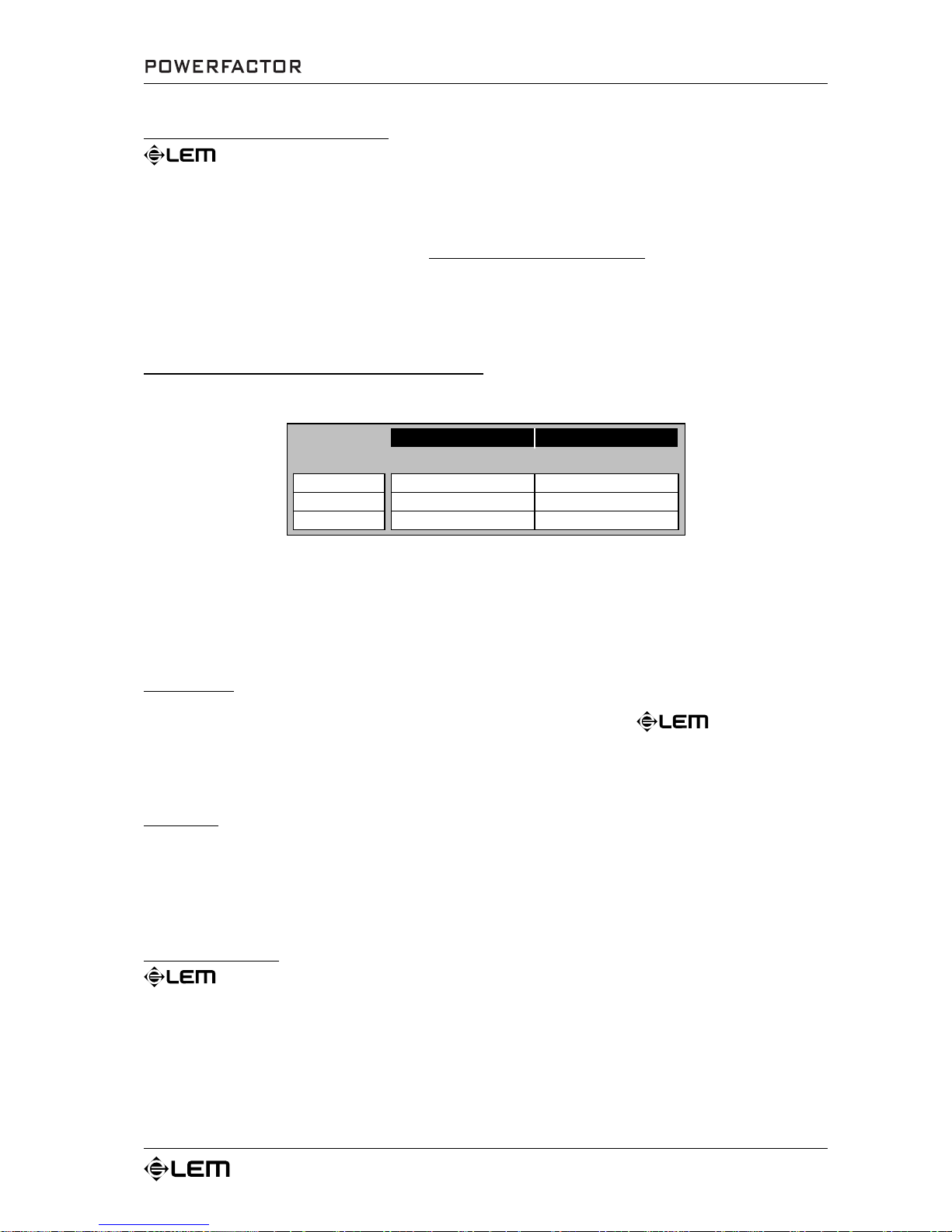
All the models in the POWERFACTOR Series can supply very high power.
PO WERFACT OR 3 PO WERFACT OR 5
IM PEDANCE
8
Ω
2 x 450 W 2 x 750 W
4
Ω
2 x 820 W 2 x 1360 W
2
Ω
2 x 1500 W 2 x 2500 W
PO WER RMS
However, no matter what their maximum power output, all the models have the same weight and
dimensions: just 9.5 kg in 1 rack unit! A result that speaks for itself and can be effectively summed up
as: “really small, really light and really powerful amplifiers”.
Total control
As well as the structural technology, a series of patented devices ensures cutting edge figures for all
parameters: slew rate, damping factor, distortion, frequency response, etc. POWERFACTOR
amplifiers are thus always kept under total control.
The sound
Lastly, particular care has also been taken with tone quality, to guarantee high-definition reproduction of
all frequencies: from the crystal-clear sound of the high frequencies, to the perfect intelligibility of an upfront full-bodied bottom end.
Protection features
POWERFACTOR amplifiers are fitted with a series of extremely efficient protections, which
ensure they can always be used with utmost security.
Cooling system and thermal protection
A highly sophisticated cooling system prevents any problems of a thermal nature.
A built-in fan creates handles cooling: the front-to-rear flow-through system takes in air through the vents
on the front panel, passes it through the entire unit and feeds it out through the slits on the back.
Introduction
Page 6

4
A special thermal control device constantly varies fan speed according to the temperature picked up by
the sensors located on the heat sink. This type of control ensures that airflow always matches temperature
conditions, ensuring the fan is even quieter when the amplifier is running with low signals and reducing
dust build-up inside the unit.
At high temperatures, the fan is able to drive a very large amount of air.
If, in spite of this, the temperature of the heat sink is still too high (for example in the event of installation
in small areas with poor air circulation), when 60°C is reach, the “TEMP” LED starts to flash and thermal
control device gradually reduces the output gain.
If the temperature exceeds 70°C (for example due to air vent blockage), the “TEMP” LED remains steadily
lit and another device intervenes, muting the amplifier and cutting off the power supply.
As soon as the temperature returns to safe operating levels, the system is automatically reactivated and
the “TEMP” LED goes off.
NOTE: it’s possible to reduce the temperature by reducing the output volume.
Current protection on the output transistors
This device trips in the event of short-circuiting or overloading at output transistor level. It’s absolutely
unnoticeable when not enabled.
When this protection trips, the “PROTECT” LED lights up.
Loudspeaker protection
In the event of output transistor breakdown or other forms of faulty operation sending DC voltage or
excessive subsonic frequencies to one or both outputs, a protection device immediately cuts off the power
supply circuit of both channels of the amplifier, thus preventing current peaks from reaching the
loudspeaker enclosures and damaging them.
To protect the loudspeaker enclosures from dangerous transients or signal peaks, on the other hand,
the outputs are muted every time the amplifier is switched on or off. Muting takes place as follows: 4
seconds’ muting (also known as “delay”) when switching on and instantaneous muting when switching
off.
Soft clipping
An efficient circuit immediately picks up any signal that could cause the amplifier to “clip” and intervenes,
controlling excessive distortion, but at the same time retaining maximum dynamics.
High-frequency protection
A dedicated device filters fixed VHF signals and interference outside the audio range.
Protection against RF interference
An ultrasonic network decouples RF signals from the outputs and keeps the amplifier stable even with
reactive loads.
Introduction
Page 7
5
Rules for installation and use
ATTENTION !!!
The POWERFACTOR series amplifiers generate high voltage on output.
To avoid the risk of electric shocks, DO NOT TOUCH any bare wires when the unit is
switched on.
This manual contains important information for correct safe use: read it carefully
before using your amplifier.
✔ ✔
✔ ✔
✔
Connection to the mains supply
Before connecting the amplifier to the mains socket, always make certain that:
- the electric system and mains socket have an adequate grounding, compatible with the safety norms
(if you’re uncertain, consult specialized personnel);
- the mains voltage corresponds to that shown on the rear of the unit (an allowance of up to ±10% is
accepted);
- the power cord is not damaged and has no bare wires;
- the on/off switch is in the OFF position.
Make sure the amplifier is also off before disconnecting the power cord from the mains socket.
✔ ✔
✔ ✔
✔
Switching on and off
In your sound reinforcement system,
always switch on the amplifier after all the other equipment and
always switch it off before anything else, if possible with the Gain controls set at minimum: this will avoid
annoying and sometimes dangerous signal peaks.
(NB: when switched on, the amplifier is “muted” for approximately 4 seconds.
It’s normal that when the unit is switched on the various LEDs on the front panel light up for a few
moments).
✔ ✔
✔ ✔
✔
Installation and use
Your POWERFACTOR amplifier generates decidedly high power, so install it in locations which ensure
correct air circulation. Avoid long exposure to direct sunlight, sources of strong heat, powerful vibrations,
very dusty or particularly damp surroundings or (even worse) rain: this will avoid possible faulty operation,
deterioration or even electric shocks and fires.
The air for cooling the unit is forced in through the vents in the front panel and out through those on the
rear panel, so make certain that there’s sufficient space round the amplifier to allow adequate air
circulation.
If racks or flight-cases are used, make sure that airflow is unobstructed:
don’t install the amplifiers in
racks or flight-cases with closed backs.
Since part of the heat is dissipated via the metal bottom of the amplifier,
it’s advisable to install the
amplifiers with at least one rack unit space between them.
✔ ✔
✔ ✔
✔
Audio connections
Remember to always connect and disconnect other units with the amplifier switched off.
Always use good quality cables of the appropriate type, opportunely described in the “Connection Cables”
chapter of this manual.
Take care of your connector cables, a very frequent cause of small/big problems. Check their condition fre-
quently . Always grip them by the connector, avoid pulling them forcefully and wind them without forming knots
or sharp bends: they’ll last longer this way and be more reliable, which is a definite advantage.
Rules for installation and use
Page 8
6
✔ ✔
✔ ✔
✔
Preventing or identifying interference
First of all, check that the amplifier is installed in a place free from industrial or RF (radio frequency) interference. Avoid installing your equipment very near radio or TV sets, mobile phones, etc., as these can cause
noisy interference.
When connecting the other components of your sound system, watch out for the so-called “ground loops”,
which could cause hum and jeopardize the amplifier’s excellent Signal-to-Noise and low distortion characteristics.
The best way (even if not always feasible) to avoid ground loops is to connect the electric ground of all the
equipment to a single central point (the so-called “star” system). In this case, the central point in sound
systems is the mixer.
To help identify the cause of any interference, connect the various sections of the mixer to the rest of the
equipment in the following order, listening to the resultant sound as you proceed with connection:
Outputs: amplifiers + loudspeaker enclosures (Master outputs);
amplifiers + monitors (AUX outputs);
effects (AUX outputs or EFF send/return).
Inputs: instruments with line signals (keyboards, samplers, recorders, etc.);
microphones (lastly and one by one).
✔ ✔
✔ ✔
✔
Protection and maintenance
The amplifier is built in shock-resistant material. Nevertheless, protect it during transport with a flight-case to
avoid the risk of any casual accidents.
After long periods of use, particularly in dusty surroundings, accumulated dust may interfere with the
unit’s cooling.
Without opening the amplifier and making certain it’s disconnected from the mains supply,
dust can be removed with a jet of compressed air, forcing it out through the chassis’ louvers. If the dust
build-up is excessive, don’t open the amplifier, as you could run the risk of serious electric shocks: contact
the nearest
Assistance Centre
Any dust on the outside of the chassis should be removed using a dry soft cloth or brush.
Never use
alcohol, acetone or solvents of any kind.
The amplifier requires no further maintenance.
✔ ✔
✔ ✔
✔
In the event of breakdown
All user-adjustable parts are external and easily accessible.
Never open the amplifier: you could run the risk of serious electric shocks.
In the event of breakdown, contact the nearest
Assistance Centre
✔ ✔
✔ ✔
✔
Keeping the documentation
Keep this user’s manual for future consultation.
Also remember that the mixer will get a better price on the secondhand market if (as well as being in good
condition) if it has its original documentation and packaging.
Rules for installation and use
Page 9
7
Functions & Controls
Functions & Controls
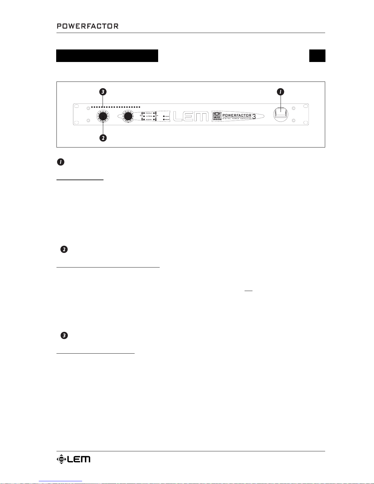
POWER ON/OFF
ON - OFF switch.
The amplifier has “SOFT-START”, i.e. a device that allows to avoid high energy consumption when the
unit is switched on.
This device also delays the power feed to the load for 4 seconds, thus avoiding dangerous signal peaks
and possible damage to the speakers.
For this same reason, power output is cut off immediately when the amplifier is switched off.
NB: remember that in a sound system, the amplifiers should always be switched on last and switched off first, if possible with
their input controls set at maximum attenuation.
INPUT ATTENUATORS
Input gain attenuator potentiometers.
Attenuate the level of the external signal sent to the respective channels of the amplifier.
Continuously variable values, expressed in dB, are between:
“
∞∞
∞∞
∞”: fully closed (the signal is completely attenuated and therefore not sent to the channel
of the amplifier) and
“0”: fully open, i.e. nominal level (the signal is not attenuated in any way, so is fed to the amplifier
channel at the same level at which it arrives on input).
NB: between -30dB and 0dB the attenuators intervene with a logarithmic scale.
METERs
Output level LED indicators.
Allow to monitor the level of the respective channels of the amplifier.
Each of the 10 segments corresponds to 3dB and indicates the following conditions:
Green LEDs : indicate normal running conditions.
Yellow LEDs : light up at -6dB.
Red LEDs : indicate clipping (the audio signal level exceeds the output capacity of the
amplifier channel).
NOTE: when setting the levels, some elementary rules must be followed to ensure clean, undistorted sound. To achieve a
good Signal-to-Noise ratio and a wide dynamic range, for example, avoid allowing the red LEDs to light up continually.
It must also be remembered that an excessively high signal can damage hearing as well as amplification systems.
Page 10
8
Functions & Controls
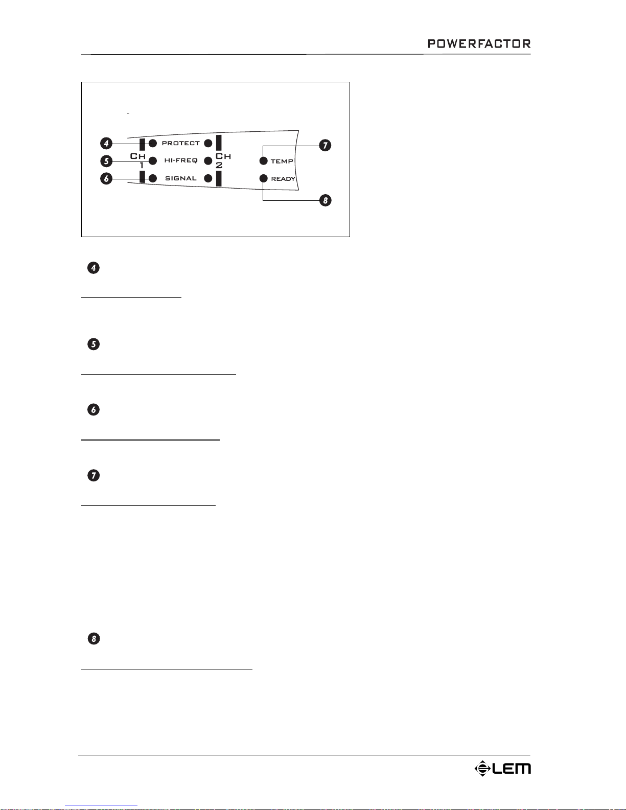
LEDs
The front panel is fitted with a series of
LED indicators.
“PROTECT”, “HI-FREQ” and “SIGNAL”
are specific for each channel.
“READY” and “TEMP” are common to
both channels.
PROTECT LEDs
Protection indicators.
Indicate the intervention of any protections on the respective channels of the amplifier.
NB: for a detailed description, see the PROTECTIONS section in the Introduction chapter.
HI-FREQ LEDs
High frequency filters’ indicators.
Indicate the intervention of a filter for fixed VHF signals and interference outside the audio range.
SIGNAL LEDs
Indicators of signals on input.
If lit, indicate that the relative inputs of the amplifier channels are receiving an audio signal.
TEMP LED
Thermal protection indicator.
The LED’s status indicates 3 possible conditions.
LED off : protection disabled, normal running conditions.
LED flashing : protection enabled, 60°C reached, the thermal control device gradually
reduces output gain.
LED lit steadily : protection enabled, 70°C exceeded, the amplifier is “muted” and the power
supply cut off until safe temperature levels are restored.
NB: remember that it’s possible to reduce the temperature by lowering the output volume.
For a detailed description, see the PROTECTIONS section in the Introduction chapter.
READY LED
Indicates regular amplifier operation.
Page 11
9
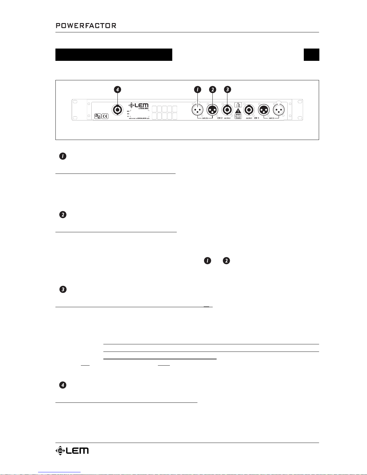
INPUTS
Balanced XLR-F connectors (0 dB / 30 k
ΩΩ
ΩΩ
Ω).
The inputs of the amplifier’s two channels. Can receive balanced or unbalanced high impedance line
signals from equipment with high level outputs.
NB: Whenever possible, use balanced cables. In any case, avoid using a balanced cable for one channel and an unbalanced
one for the other, as this would cause a considerable difference in channel levels.
LINK
Balanced XLR-M connectors (0 dB / 30 k
ΩΩ
ΩΩ
Ω).
These connectors are connected in parallel with the respective XLR-F connectors. This enables a second
unit (e.g. another amplifier) to be daisy-chained to the first. It’s thus possible to power several amplifiers
using the same signal, forming more powerful sound reinforcement systems.
NB: as they’re connected in parallel, the only difference between and is the type of connector.
In fact: a) the signal can be connected without distinction to either connector.
b) the signal can be “forwarded” to the input of another amplifier using the free connector.
OUTPUTS
Neutrik SPEAKON connectors (minimum impedance 2
ΩΩ
ΩΩ
Ω).
The outputs to be connected to the loudspeaker enclosures.
To avoid possible damage to the loudspeaker enclosures, only connect enclosures or speaker systems
compatible with the power load and impedance limits indicated for the amplifier (regarding this, consult
the “Technical specifications” chapter for reference to your specific amplifier model).
ATTENTION !
POWERFACTOR amplifiers cannot be used in BRIDGE mode, so to avoid serious
risks of electric shocks, DO NOT use any power output connections or wiring
other than those indicated in this manual.
NOTE: use only loudspeaker enclosure cables, never signal cables, i.e. those normally used for microphones, instruments
and audio equipment in general (regarding this, consult the “Connection cables ” chapter).
A.C. ~
Power cord socket - Neutrik POWERCON connector.
For connecting the amplifier to the mains supply using a special high-security cable (supplied as standard).
Connection panel
Connection panel
Page 12
10
Connection examples
Connection examples
Page 13
11
Connection examples
Page 14
12
Connection examples
Page 15
13
Connection cables
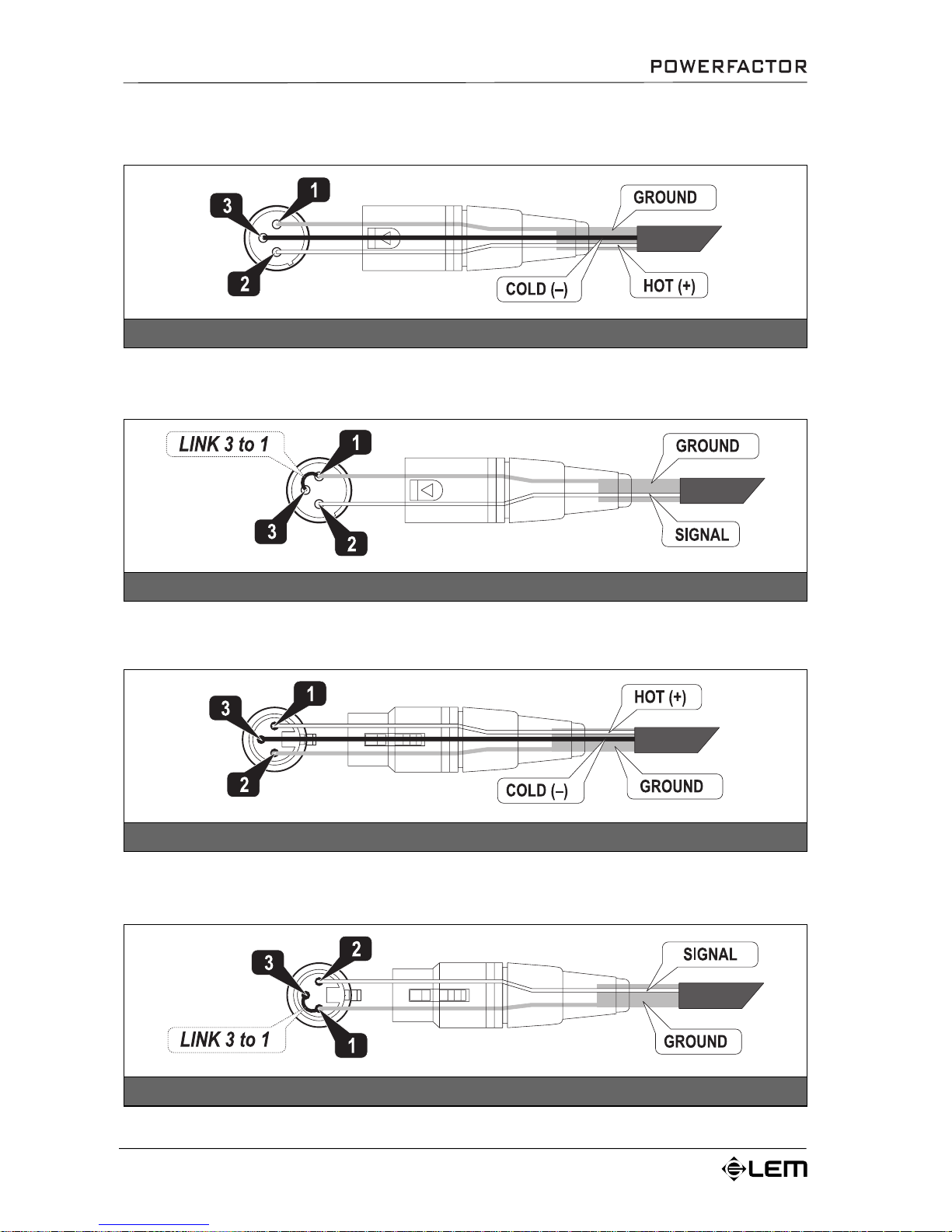
The following diagrams show the wiring of the connectors that can be used with the POWERFACTOR series amplifiers.
To connect the mixer outputs to the amplifiers inputs, make certain to always use balanced signal cables: the use of unbalanced
cables could in fact probably cause annoying hum and noise.
To connect the amplifier to the loudspeaker enclosures always use power cables (speaker cables made up of two wires, normally
with a large cross-section).
Take care of your connector cables, always gripping them by the plugs, avoid pulling them directly and winding them without
knots or bends: they’ll last longer and be more reliable, which is to your advantage. Check periodically that your cables are in
good condition, correctly wired and with perfectly efficient contacts: in fact many problems and drawbacks (false contacts,
ground hum, crackles, etc.) are caused by the use of unsuitable or damaged cables.
Connection cables
Power cables
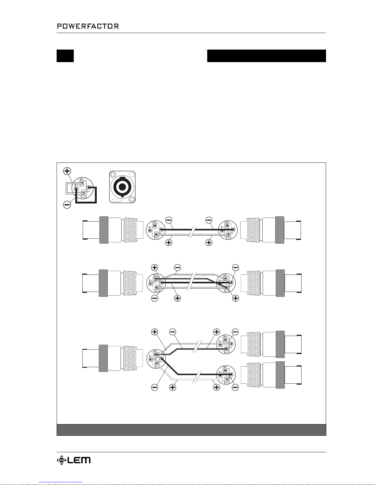
SPEAKON power connector
The 4-way SPEAKON connector of the POWERFACTOR’s power outputs has
the PIN 1+ / 2+ and 1- / 2- linked together. This allows the power to be carried
along 4 wires instead of 2, thus reducing the dissipation of energy, especially
in case of very long distances. 3 different cables can be used with this kind of
connection, as shown below.
2-wire cable: it’s a standard cable, which can be used in normal conditions (not very long distances) and which
is connected only to the PIN 1+ and 1- of the output SPEAKON connector.
4-wire cable: this cable can be used in case of very long distances and is connected to all the 4 PINS of the
output SPEAKON connector. On the opposite end, the 4 wires are linked together in pairs and connected to the
PIN 1+ and 1- of the connector inserted into the loudspeaker system.
4-wire cable with dual SPEAKON: this cable can be used to connect to the amplifier two loudspeaker enclosures
instead of one and allows, at the same time, the power to be carried along two wires, reducing the energy
dissipation. The PIN 1+ and 1- are connected to the first enclosure and the PIN 2+ and 2- are connected to the
second one.
Page 16
14
Connection cables
Unbalanced XLR-F connector
Unbalanced XLR-M connector
Balanced XLR-F connector
Balanced XLR-M connector
Signal cables
Page 17
15
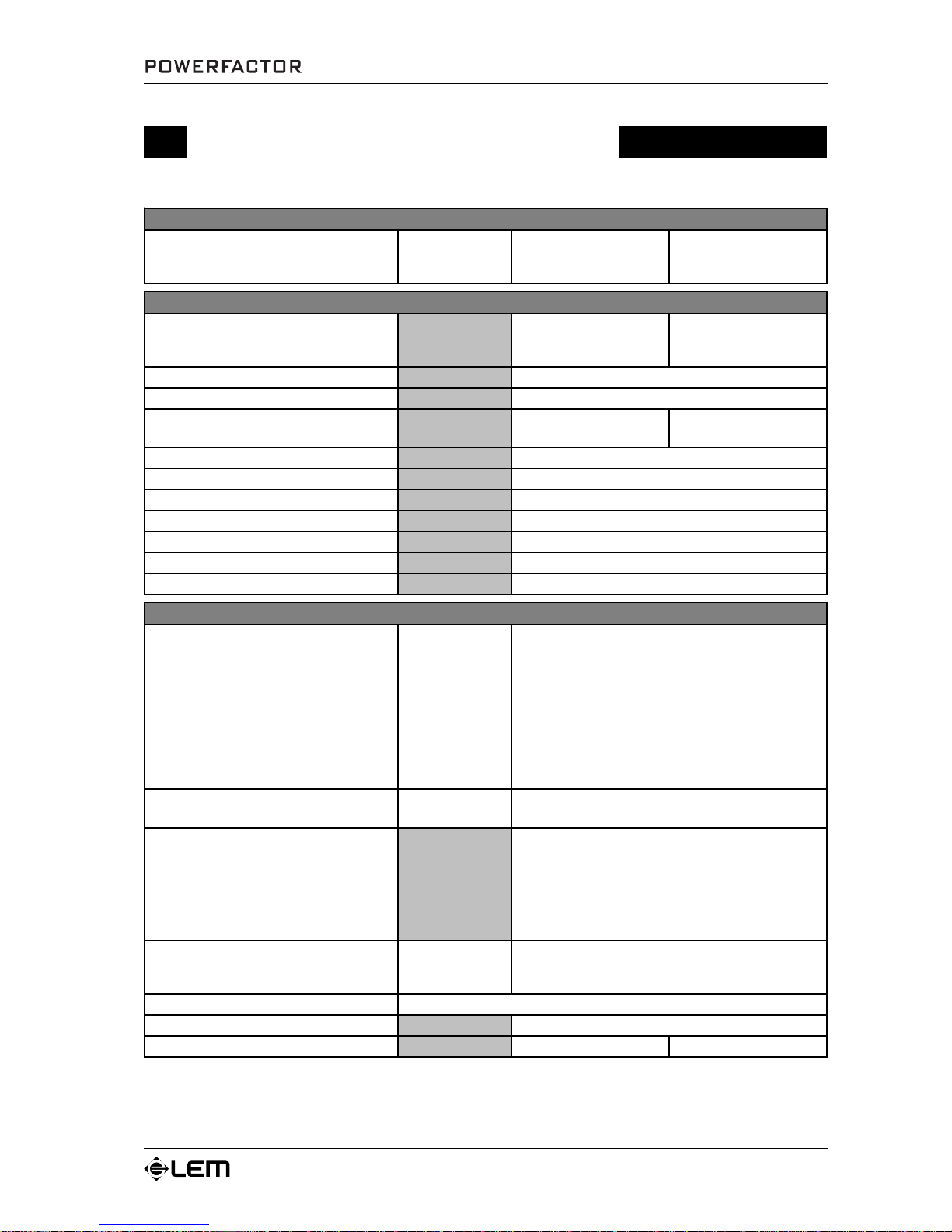
Technical specifications
Technical specifications
POWER SPECIFICATIONS
POWERFACTOR 3
POWERFACTOR 5
EIAJ impulse output power
1kHz, THD maximum 1%
Both channels
2 Ohms
4 Ohms
8 Ohms
1500+1500
820+820
450+450
2500+2500
1360+1360
750+750
ELECTRICAL SPECIFICATIONS
POWERFACTOR 3
POWERFACTOR 5
INPUT SENSITIVITY
0dB (0.775V)
+11 dB (2.9V)
with internal setting
0dB (0.775V)
+X13 dB (3.6V)
with internal setting
INPUT IMPEDANCE
FREQUENCY RESPONSE
VOLTAGE GAIN
+38 dB
+26 dB with internal setting
+40 dB
+26 dB with internal setting
SLEW RATE
DAMPING FACTOR
CROSSTALK
S/N ratio
Harmonic distortion THD
Intermodulation distortion SMPTE
Intermodulation distortion DIM 100
GENERAL SPECIFICATIONS
POWERFACTOR 3
POWERFACTOR 5
PROTECTIONS
AMPLIFIER
LOUDSPEAKERS
CONTROLS
INDICATORS
CONNECTORS
INPUT
OUTPUT
POWER SUPPLY
DIMENSIONS
WEIGHT
9.5 kg
9.5 kg
483x44x450 mm (WxHxD)
<0.02% from 0.1W to full power (typical <0.01%)
ON/OFF switch
Input level control for each channel
SIGNAL LEVEL: 2 x 10-LED bar
PROTECT: 2 red LEDs
HI-FREQ: 2 yellow LEDs
SIGNAL: 2 green LEDs
ON/READY: 1 green LED
TEMP: 1 red LED
1 XLR-F + 1 XLR-M in parallel for each channel
1 4-way SPEAKON for each channel
see label on the apparatus
Short circuit
Thermal protection
Reactive load driving capability
AC and DC protection
ON/OFF MUTE
VHF protection
Long-term output power limiting
CLIP LIMITER
50 V/µs (input filter by-passed)
100Hz = 400, 10kHz = 400
10 kOhms (balanced)
10÷ 40000 Hz (-0.5dB)
-90 dB
-100 dB
<0.5% from 0.1W to full power (typical <0.1%)
<0.5% from 0.1W to full power (typical <0.1%)
Page 18
16
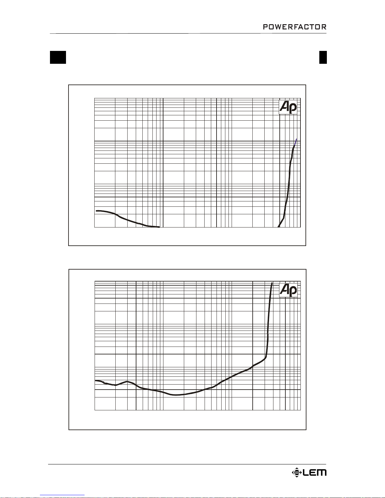
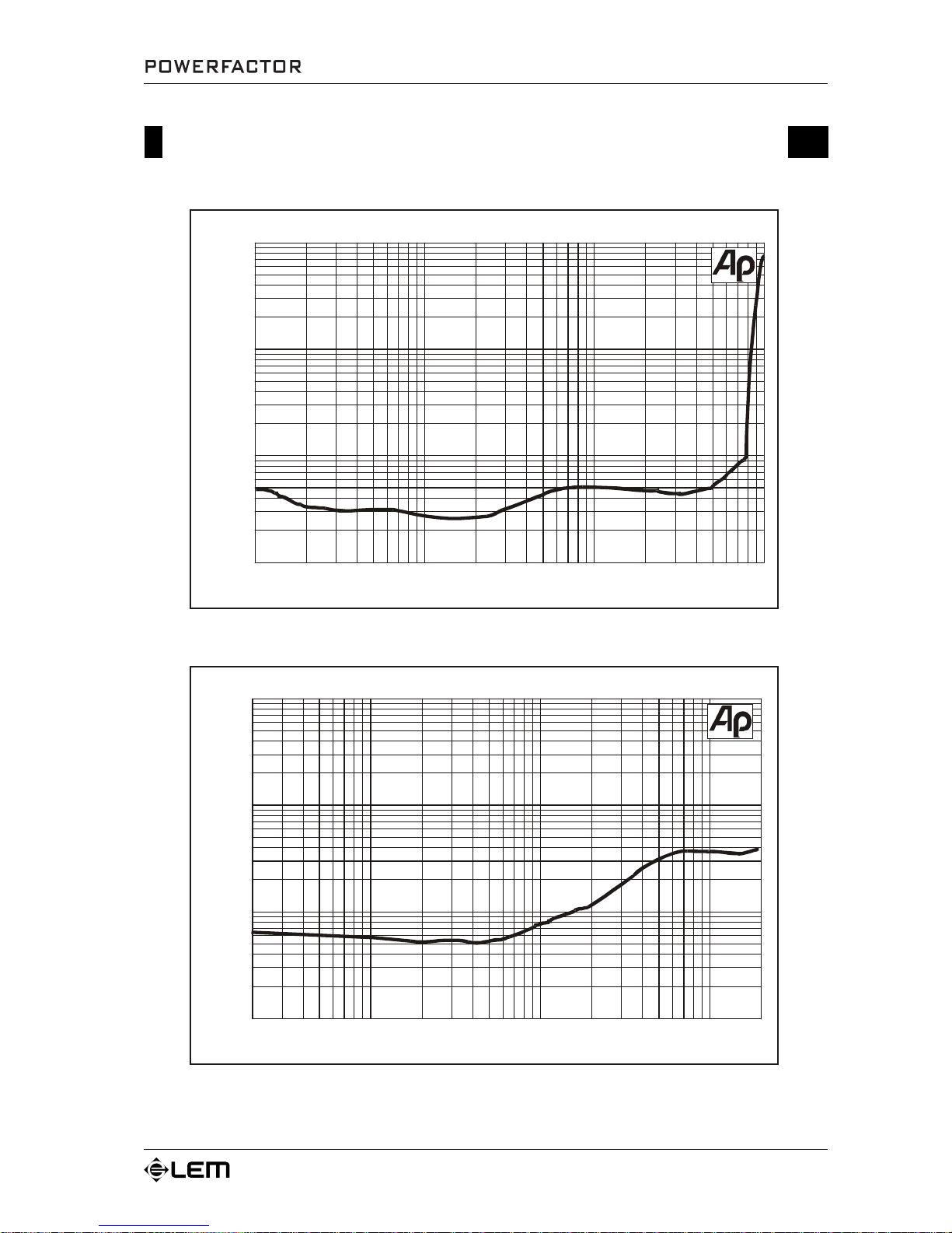
POWERFACTOR 3 response curves
%
0.01
10
0.02
0.05
0.1
0.2
0.512521k5102050100
200
500
W
POWERFACTO R 3 Intermodulation SMP TE V s. Power
0.01
10
0.02
0.05
0.1
0.2
0.5125%21k5102050
100
200
500
W
PO WER F A C TOR 3 In termo du la tion D IM 10 0 Vs . Po w er
Diagrams
Page 19
17
0.01
10
0.02
0.05
0.1
0.2
0.5125%21k5102050
100
200
500
W
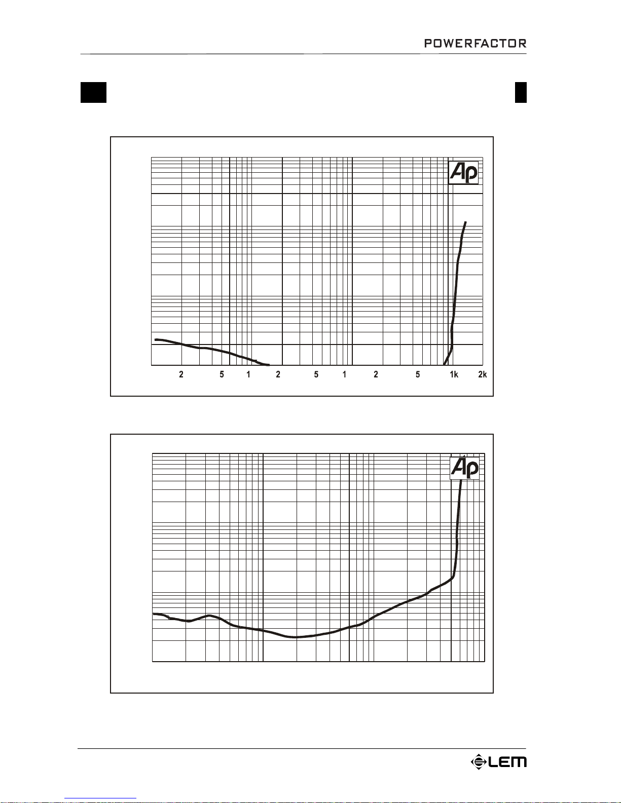
P OWERFAC TOR 3 THD : Vs. Power 4 Oh m
0.01100.02
0.05
0.1
0.2
0.5125%2010k
20k50100
200
5001k2k5kHz
POWERFACTO R 3 THD Vs. Freq. 8 Ohm (1/3 rated output power)
POWERFACTOR 3 response curves
Diagrams
Page 20
18
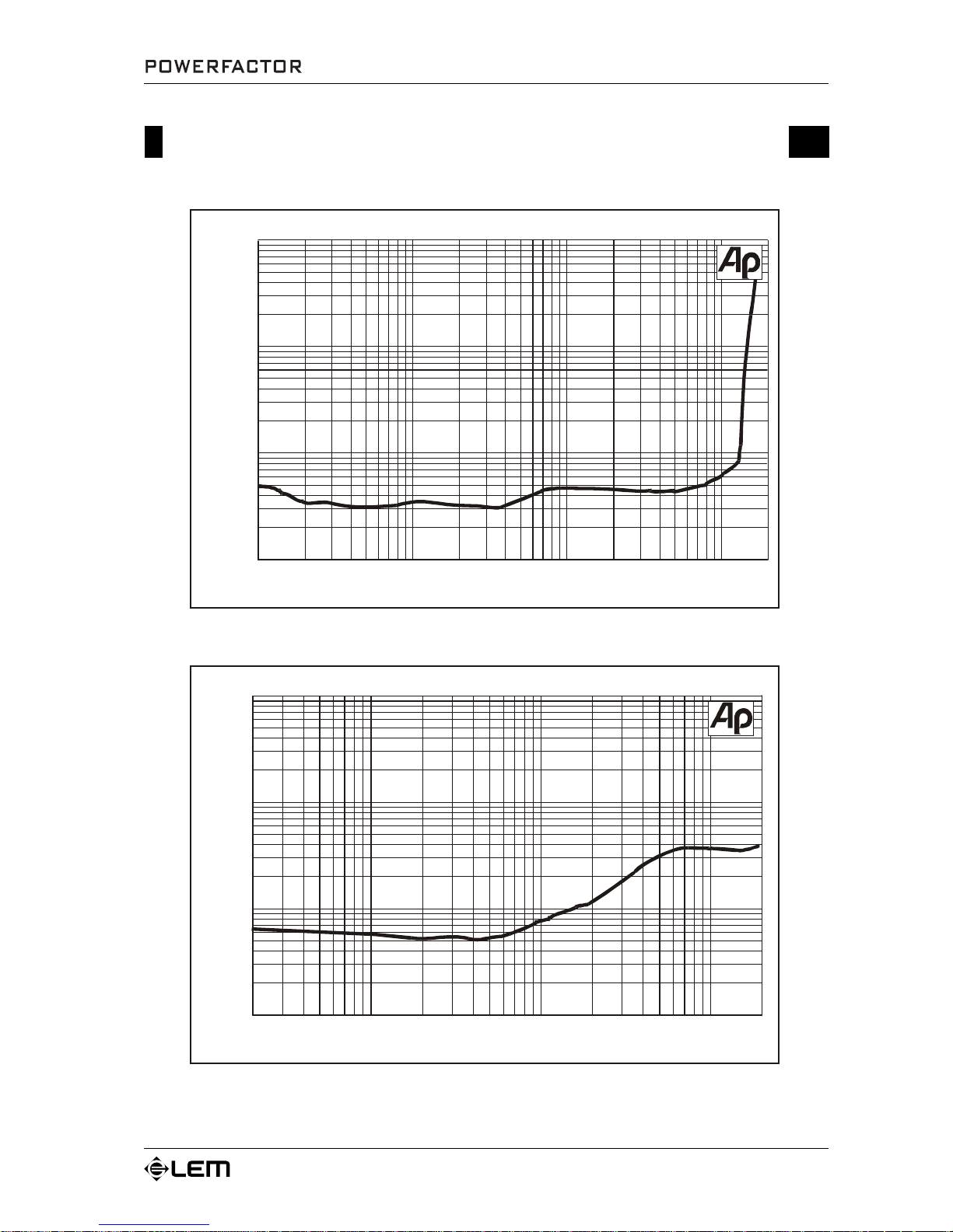
POWERFACTOR 5 response curves
0.01
10
0.02
0.05
0.1
0.2
0.5125%21k5102050
100
200
500
W
POWERFACTO R 5 Intermodulation SM PTE V s. Power
POWER FA CTOR 5 In te rmodu la tio n DIM 1 0 0 V s . Po wer
%W10
0.05
0.1
0.2
0.5
125
0.01
0.02
Diagrams
Page 21
19
POWERFACTOR 5 response curves
0.01100.02
0.05
0.1
0.2
0.5125%
21k5102050100
200
500
W
P OWERFAC TOR 5 THD: Vs. Power 4 Oh m
2k
0.01
10
0.02
0.05
0.1
0.2
0.5125%2010k
20k50100
200
5001k2k5kHz
POW ER FACTOR 5 TH D Vs. Freq. 8 O hm (1/3 rated output power)
Diagrams
Page 22
20
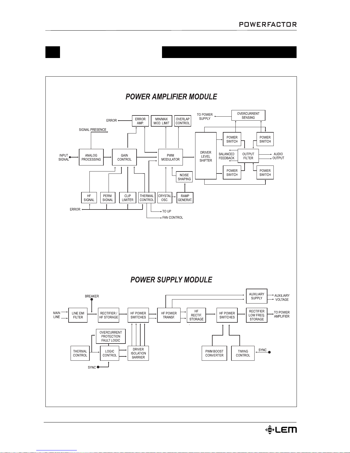
Block diagram
Diagrams
Page 23

Le informazioni contenute in questo documento sono state attentamente redatte e controllate. Tuttavia
non è assunta alcuna responsabilità per eventuali inesattezze.
Tutti i diritti sono riservati e questo documento non può essere copiato, fotocopiato, riprodotto per intero o
in parte senza previo consenso scritto della GENERALMUSIC S.p.A.
GENERALMUSIC si riserva il diritto di apportare senza preavviso cambiamenti e modifiche estetiche,
funzionali o di design a ciascun proprio prodotto.
GENERALMUSIC non assume alcuna responsabilità sull’uso o sull’applicazione dei prodotti o dei circuiti
qui descritti.
STAMPATO IN ITALIA
The information contained in this publication has been carefully prepared and checked. However no
responsibility will be taken for any errors.
All rights are reserved and this document cannot be copied, photocopied or reproduced in part or completely
without written consent being obtained in advance from GENERALMUSIC S.p.A.
GENERALMUSIC reserves the right to make any aesthetic, functional or design modification to any of its
products without any prior notice.
GENERALMUSIC assumes no responsibility for the use or application of the products or circuits described
herein.
PRINTED IN ITALY
FEDERAL COMMUNICATIONS COMMISSION
NOTE: This equipment has been tested and found to comply with the limits for a Class A digital device,
pursuant to Part 15 of FCC Rules. These limits are designed to provide reasonable protection against harmful
interference when the equipment is operated in a commercial environment. This equipment generates, uses
and can radiate radio frequency energy and, if not installed and used in accordance with the instruction
manual, may cause harmful interference to radio communications. Operations of this equipment in a
residential area is likely to cause harmful interference in which case the user will be required to correct
the interference at his own expense.
CAUTION: Changes or modifications to this product not expressly approved by the manufacturer could
void the user's authority to operate this product.
Page 24

Sales Division: 47842 S.Giovanni in Marignano (RN) – Via delle Rose, 12 – tel. +39-0541-959511 – fax +39-0541-957404
Internet: http://www.lemaudio.com
 Loading...