

Page 1
Leica XL Universal Base
User Manual
Page 2
Important Safety Notes
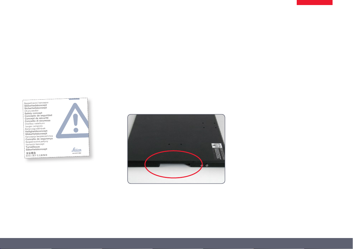
Safety concept
Before using your microscope for the first time,
please read the “Safety concept” brochure
included with your instrument. It contains additional information about handling and care.
Transport and assembly
The Leica XL Universal Baseplate is very
•
heavy! To prevent injury and property
damage, have someone help you when transporting, setting up and positioning this unit!
For optimum lifting, grip the base by the
recesses provided for this purpose.
Use in clean rooms
The Leica XL Universal Baseplate can be used in
clean rooms without any problems.
Cleaning
Please follow the cleaning instructions provided
on page 14.
Leica XL Universal Base User Manual 2
Page 3
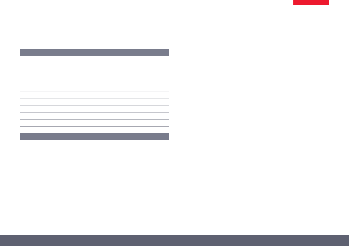
Table of Contents
Assembly
Installing the Base and Focusing Column 5
Installing the Inspection Table 6
Installing the XL Extension 7
Assembling the Optics Carrier 8
Cables: Connections 9
Cables: Cable Duct 10
Motorized Focus: Restricting the Travel Path 11
ESD Terminals 12
Assembling the Remaining Components 13
Cleaning the Focusing Column 14
Dimensional Drawings
Dimensions 16
Leica XL Universal Base User Manual 3
Page 4
Assembly
Leica XL Universal Base User Manual 4
Page 5
Installing the Base and Focusing Column
Tools used
Allen key provided ★
Assistance for installation
Installing the focusing column will be
considerably easier if you have someone
help you.
The Leica XL Universal Baseplate is
predrilled, both on the longitudinal and
on the lateral sides, with the holes necessary
for installing the base. If, however, you plan to
use the inspection table with the 300×300 mm
travel range, the focusing column must be
installed on the lateral side.
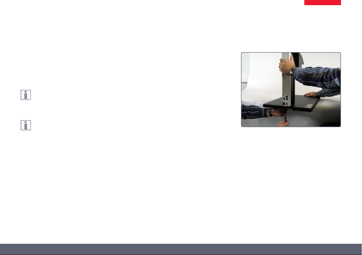
Installing the column
1. Place the Leica XL Universal Baseplate onto
the table so that the desired installation
holes point over the edge of the table.
Move the Leica XL Universal Baseplate
•
only far enough over the table edge to
make the drill holes accessible. If you pull the
baseplate too far over the edge of the table, it
can fall. This may lead to injury or damage.
2. While having another person, if possible,
hold the Leica XL Universal Baseplate
steady, screw the focusing column in place
using the screws provided.
What is next?
If you plan to use an inspection table, ★
continue from the next page of the Installation Instructions.
If you do not intend to use an inspection ★
table, skip to page 7 of the Installation
Instructions.
Leica XL Universal Base User Manual 5
Page 6

Installing the Inspection Table
Tools used
Allen key provided ★
The inspection table (1) is attached to
the base using the assembly bar (2)
provided.
1
2
After installing the assembly bar, the
inspection table is simply attached using
setscrews — its own weight is sufficient for
ensuring a secure position.
Assembly
1. Place the assembly bar over the inspection
table at a minimum distance of 110 mm
from the focusing column.
2. Tighten the screws on the assembly bar to
affix it.
3. Place the inspection table onto the assembly bar so that the setscrews grab in the
holes.
4. Slide the work top of the inspection table
towards the focusing column. Be sure that
the work top cannot touch the focusing
column when it is fully extended.
5. If the work top touches the focusing column,
remove the inspection table. Attach the
assembly bar a little further from the focusing column.
Leica XL Universal Base User Manual 6
Page 7

Installing the XL Extension
Tools
Allen key, 4mm ★
Maximum load capacity
The XL Extension is designed for a
•
maximum weight of 8 kg! This value,
however, is hardly reached in practice, as the
following sample arrangement shows:
• LeicaM205Aopticscarrier
• 0.5×trinoculartube
• 2×eyepieces
• LeicaDFC420Cdigitalcamera
• LeicaLED5000MCIillumination
• 1.0×planapochromaticobjective
Together, all of these components weigh 6.6 kg
and can be used without problem.
Installing the XL Extension
1. Place the XL Extension on the focusing
column so that the screw fits into the thread
provided and the lug fits into the groove.
2. Press the XL Extension backwards to the
focusing column and screw it in place using
your other hand.
Leica XL Universal Base User Manual 7
Page 8

Assembling the Optics Carrier
Tools
Assembling the Optics Carrier
Allen key provided ★
1. Place the optics carrier on the XL Extension so that the screw fits into the thread
provided and the lug fits into the groove.
2. Press the optics carrier backwards to the
XL Extension and screw it in place using
your other hand.
Leica XL Universal Base User Manual 8
Page 9

Cables: Connections
The terminals
The connection to the PC and to other instruments is made using the terminals on the rear
side of the column:
1. 2× CTL2 terminals for auxiliary equipment such as the Leica SmartTouch, the
foot switch, an illuminator from the Leica
LED5000 series and other accessories from
the Leica product range.
2. Terminal for the 50-watt power supply
provided.
3. USB terminal for the connection to the PC.
3
1
2
Connecting the power supply
1. Connect the included power supply unit to
the power socket on the focusing column.
Connecting the control unit
1. Connect the control unit (such as the Leica
SmartTouch) to one of the two CTL2 terminals on the focusing column.
Leica XL Universal Base User Manual 9
Page 10

Cables: Cable Duct
The cable duct
The cable duct provides better organization by holding the cables for the illumi-
nation.
The cover for the cable duct consists of
two elements, which can be removed
and installed independently of each other.
A shorter cover is included as standard
equipment. It can be used to replace a
standard-length cover. The gaps created using
the shorter cover can be used to feed the cable
into and out of the cable duct.
Inserting the cables
1. Remove the standard cover from the cable
duct.
2. Place the cable into the cable duct.
3. Install the shorter cover. Press this cover
onto the cable duct until you hear it click
into place.
Leica XL Universal Base User Manual 10
Page 11

Motorized Focus: Restricting the Travel Path
Depending on the work situation, it may
be necessary to restrict the maximum
travel path of the microscope. This prevents the
following:
Injuries when manipulating the specimen ★
because the fingers or hand get pinched.
Accidental contact between the lens and ★
the specimen, and potential resulting
damage.
Readjusting the motorized focus
The motorized focus is factory-adjusted and
normally does not need to be readjusted—
even if the maximum travel path is changed.
Exception: If the power fails while the
•
motorized focus is moving, the position
data are lost. In this case, the calibration must
be repeated using the Leica LAS software or the
Leica SmartTouch™. To do so, please consult the
respective manual.
Restricting the bottom travel range
1. Move the motorized focus into the lowest
position you want to reach.
2. Unscrew the screw of the limit stop on the
side of the focusing column.
3. Push the limit stop to the height of the
motorized focus.
It is easiest to move the limit stop by keeping
the Allen key inserted and moving it upwards.
4. Tighten the screw of the limit stop.
Leica XL Universal Base User Manual 11
Page 12

ESD Terminals
The Leica XL Universal Baseplate is
equipped with two ESD terminals.
Another terminal is located on the inspection
table.
Corresponding cables with banana plugs
are not included as standard equipment.
Leica XL Universal Base User Manual 12
Page 13

Assembling the Remaining Components
For instructions on installing the remain-
ing components, please refer to the
documentation that was included with your
microscope.
Leica XL Universal Base User Manual 13
Page 14

Cleaning the Focusing Column
To guarantee trouble-free functionality
for years, the focusing column should be
cleaned regularly. Otherwise, dirt and dust can
accumulate on the rollers, making it difficult or
even impossible to focus accurately.
For cleaning, use a soft, lint-free cloth. Tough
dirt can be removed using a mild cleaning
agent.
Leica XL Universal Base User Manual 14
Page 15

Dimensional Drawings
Leica XL Universal Base User Manual 15
Page 16

Dimensions
400
292
600
400
369
min. 290
83.4
28.5
max. 420
631
600
54
369
min. 290
83.4
max. 420
600
Leica M80 with universal base, XL Extension and binocular ErgoTube®
Leica XL Universal Base User Manual 16
 Loading...