

Leica VT1200S, VT1200 User Manual
Operating Manual
Leica VT1200 and VT1200S
V1.1 English – 05/2007
Always keep this manual with the instrument.
Read carefully before working with the instrument.
Leica VT1200
Leica VT1200 S
Microtome with
Vibrating Blade


Note
The information, numerical data, notes and value
judgments contained in this manual represent the
current state of scientific knowledge and stateof-the-art technology as we understand it following thorough investigation in this field. We are
under no obligation to update the present manual periodically and on an ongoing basis according to the latest technical developments, nor to
provide our customers with additional copies,
updates etc. of this manual.
To the extent permitted in accordance with the
national legal system as applicable in each individual case, we shall not be held liable for erroneous statements, drawings, technical illustrations etc. contained in this manual. In particular,
no liability whatsoever is accepted for any financial loss or consequential damage caused by or
related to compliance with statements or other
information in this manual.
Statements, drawings, illustrations and other information regarding the contents or technical
details of the present manual are not to be
considered warranted characteristics of our
products.
These are determined only by the contract provisions agreed between ourselves and our customers.
Leica reserves the right to change technical specifications, as well as manufacturing processes,
without prior notice. Only in this way is it possible
to continuously improve the technology and manufacturing techniques used in our products.
This document is protected under copyright laws.
All copyrights to this documentation are held by
Leica Microsystems Nussloch GmbH.
Any reproduction of text and illustrations (or of
any parts thereof) by means of print, photocopy,
microfiche, web cam or other methods – including any electronic systems and media – requires
express prior permission in writing by Leica
Microsystems Nussloch GmbH.
For the instrument serial number and year of manufacture, please refer to the nameplate on the
back of the instrument.
© Leica Microsystems Nussloch GmbH
Published by:
Leica Microsystems Nussloch GmbH
Heidelberger Str. 17 – 19
D-69226 Nussloch
Germany
Phone: +49 62 24 143-0
Fax: +49 62 24 143-200
E-mail: histo_info@leica-microsystems.com
Internet: http://www.histo-solutions.com
Leica VT1200 and VT1200 S – Microtome
3

Contents
1. Important Notes .......................................................................................................................... 5
1.1 Symbols in the Text and their Meanings ........................................................................................ 5
1.2 Qualification of Personnel ................................................................................................................ 5
1.3 Intended Use/Improper Use ............................................................................................................. 5
2. Safety ............................................................................................................................................ 6
2.1 General Safety Notes ........................................................................................................................ 6
2.2 Warnings ............................................................................................................................................. 6
2.1 Transport, Unpacking and Setting up ............................................................................................. 7
3. Instrument Characteristics....................................................................................................... 8
3.1 Technical Data for the VT1200 ......................................................................................................... 8
3.1.1 Technical Data for the VT1200S....................................................................................................... 9
3.2 General Overview of the VT1200/VT1200S ................................................................................... 10
3.3 VT1200 Control Panel ....................................................................................................................... 12
3.3.1 VT1200S Control Panel .................................................................................................................... 13
4. Installation................................................................................................................................. 14
4.1 Standard Scope of Delivery for the VT1200 ................................................................................. 14
4.1.1 Standard Scope of Delivery for the VT1200S .............................................................................. 15
4.2 Packing and Setting up the Instrument ........................................................................................16
4.3 Before Commissioning the Instrument ......................................................................................... 17
5. Working with the Instrument ................................................................................................. 18
5.1 Description of the Typical Application ......................................................................................... 18
5.2 Control Elements on the VT1200 Control Panel ........................................................................... 19
5.3 Control Element on the Control Panel of the VT1200S ............................................................... 22
5.4 Installing the Accessories .............................................................................................................. 32
5.5 Routine Daily Maintenance and Switching off the Instrument – VT1200/VT1200S ............... 36
6. Operating the VibroCheck ......................................................................................................37
6.1 Using the VibroCheck with the VT1200 .........................................................................................37
6.2 Using the VibroCheck with the VT1200S ...................................................................................... 39
7. Malfunctions: Meanings and Troubleshooting .................................................................. 41
7.1 Error Messages and Troubleshooting .......................................................................................... 41
7.2 Replacing the Main Fuse ................................................................................................................ 46
8. Cleaning and Maintenance .................................................................................................... 47
8.1 Cleaning the Instrument .................................................................................................................. 47
9. Ordering Information for Optional Accessories, Consumables and Spare Parts ........ 48
10. EC Declaration of Conformity .................................................................................................56
11. Warranty and Service.............................................................................................................. 57
4
Operating Manual V1.1 – 05/2007
1. Important Notes
1.1 Symbols in the Text and their
Meanings
Dangers, warnings and cautions
appear in a gray box and are marked
by a warning triangle .
Useful tips,
i.e. important information for the user,
appear in gray boxes and are marked
by an information symbol .
(5)
(Fig.5)
Numbers in parentheses refer to item
numbers in illustrations or to the illustrations themselves.
1.3 Intended Use/Improper Use
The Leica VT1200 and VT1200S are used for sectioning in the fields of medicine, biology and
industry, and are especially designed for sectioning fixed or unfixed fresh tissue in buffer.
The instrument must be installed according to the
directions in this Operating Manual.
Any other use of the instrument is considered
improper.
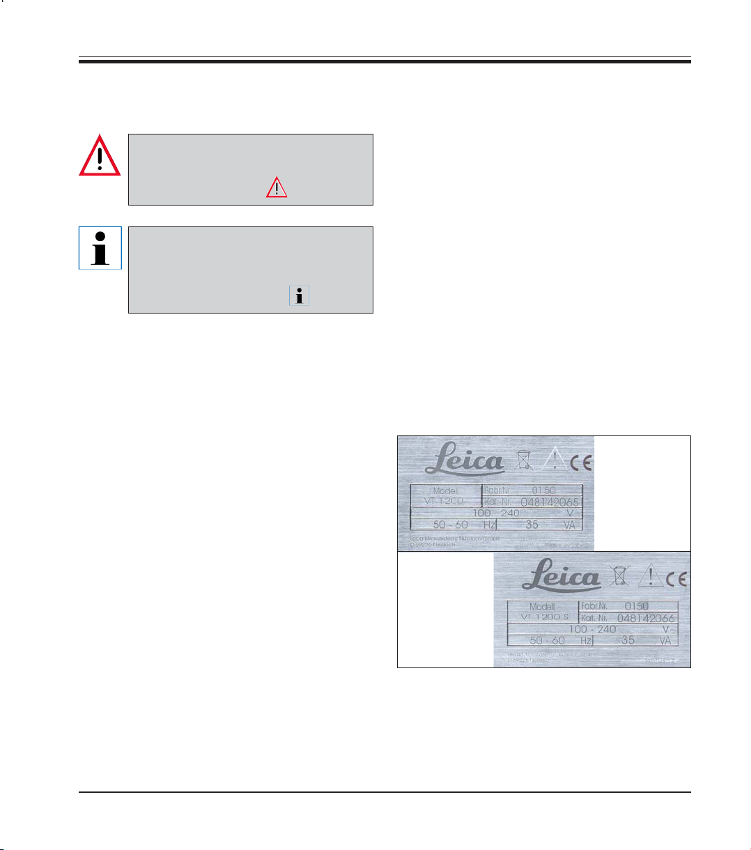
Instrument model:
All information provided in this manual applies
only to the VT1200 and VT1200S instruments described here.
A nameplate indicating the instrument serial number is attached to the rear side of the instrument.
1.2 Qualification of Personnel
The Leica VT1200 and the VT1200 S may be operated by trained laboratory personnel only.
All laboratory personnel designated to operate
the Leica instrument must read this Operating
Manual carefully and must be familiar with
all technical features of the instrument before
beginning to operate it.
Leica VT1200 and VT1200 S – Microtome
Note:
Fig. 1
When making inquiries, please make sure that you
have the following product information ready:
• Instrument model and serial number
5

2. Safety
This Operating Manual contains important instructions and information
regarding the operational safety and maintenance of the instrument.
The Operating Manual is an important part of the product, and must be read
carefully prior to startup and use and must always be kept near the instrument.
If additional requirements on accident prevention and environmental protection apply in the country of operation, this Operating Manual must be
supplemented by appropriate instructions to ensure compliance with such
requirements.
Make sure to read all of the Operating Manual before you work on or operate the instrument.
2.1 General Safety Notes
These instruments have been built and tested in accordance with the safety regulations for electrical measuring, control, regulating and laboratory
devices.
In order to maintain this condition and to ensure safe operation, the user
must follow the instructions and warnings contained in this Operating Manual.
2.2 Warnings
6
For current information about applicable standards, please refer to the CE
Declaration of Conformity on our Internet site:
www.histo-solutions.com
The safety devices installed in this instrument by the manufacturer only constitute the basis for accident prevention. Operating the instrument safely is,
above all, the responsibility of the owner, as well as the designated personnel who operate, service or clean the instrument.
To ensure trouble-free operation of the instrument, make sure to comply
with the following instructions and warnings.
Operating Manual V1.1 – 05/2007
Caution: Extremely sharp blades pose risk of injury when touched!
Proper handling
Always be exceptionally careful when handling the blades!
Do not leave open blades lying around after removal.
Always make sure to handle the blade in a way that will not cause you injury.
All appropriate safety precautions must be met to avoid the risk of infection.
Wearing safety gloves, a mask and safety goggles – in accordance with the "Working with
Substances that Pose a Health Risk" guidelines – is absolutely mandatory.
The instrument may be opened by authorized service personnel only.
Always disconnect the power plug before opening the instrument.
Always switch off the instrument using the power switch and disconnect the power plug before
replacing the fuse. The use of fuses other than those installed at the factory is not permitted.
2. Safety
Fresh tissue poses risk of infection!
Fire hazard from uncovered magnifier! Cover the magnifier during work breaks!
2.1 Transport, Unpacking and Setting up
• When unpacking the instrument, compare the parts received with the
parts ordered. If the parts received do not match your order, contact the
sales company responsible for your order immediately.
• Please refer to "Technical Data" before connecting the instrument to a
power supply.
• Never connect the instrument to a power socket that does not have a
protective conductor terminal.
The instrument must be set up so that the main power switch on its right side (item 7 in Fig. 14) is
easily accessible at any time.
Because the weight of the instrument is approx. 56 kg, carrying the instrument requires 2 persons
(1 carrying handle per person).
Leica VT1200 and VT1200 S – Microtome
7

3. Instrument Characteristics
3.1 Technical Data for the VT1200
General data:
Cutting frequency (± 10 %) ................................................................................................................. 85 Hz (± 10%)
Amplitude .................................................................................................... from 0 – 3mm, in 0.05 mm increments
Cutting speed (± 10 %) ...................................................................................................................... 0.01 – 1.5 mm/s
Return speed (± 10 %) ................................................................................................................................. 2.5 mm/s
Total vertical specimen stroke ................................................................................................. 20 mm (motorized)
Cutting range ............................................................................................................................... 45 mm (adjustable)
Maximum specimen size:
With standard blade holder
Specimen orientation, rotating
Specimen plate, swiveling
Section thickness adjustment .................................................................................. manual, in 1 μm increments
Ambient conditions:
Operating temperature range: .......................................................................................... min. 10 °C – max. 35 °C
Relative humidity: ....................................................................................................................................... max. 60 %
Storage temperature: ................................................................................................................................... 5 – 55 °C
Storage humidity: ............................................................................................................................................. < 60 %
Height: ........................................................................................................................ up to 2000 m above sea level
Electrical data:
Rated voltage range (± 10 %): ....................................................................................................................... 100 V – 240 V
Rated frequency (± 10 %): ..................................................................................................................................... 50/60Hz
Power consumption:................................................................................................................................................... 35 VA
Protection class: .................................................................................................................................................................. I
Power fuses: .................................................................................................................................................... T 1 A L 250 V
Pollution degree: ................................................................................................................................................................. 2
Overvoltage category: ........................................................................................................................................................ II
Electrical overload protection: ..................................................................................................................................... yes
Internal current limit for the electronics: .................................................................................................................... yes
Dimensions:
L x W x H: ................................................................................................................................ 600 mm x 250 mm x 230mm
Height with magnifier support ............................................................................................. 600 mm x 250mm x 320mm
Height with microscope: ....................................................................................................... 600mm x 250 mm x 490mm
L x W x H control unit (when the bases are folded in): ...................................................... 165 mm x 120 mm x 72mm
Weight:
Without magnifier support and control unit ............................................................................................................ 56 kg
VT1200 control unit ........................................................................................................................................................ 1 kg
Magnifier support .......................................................................................................................................................... 2 kg
Microscope support with stereomicroscope ............................................................................................................ 4 kg
.............................................................................................................
...................................................................................................................
......................................................................................................................
33 x 50 mm
360 °
0 – 10 °
8
Operating Manual V1.1 – 05/2007

3. Instrument Characteristics
3.1.1 Technical Data for the VT1200 S
General data:
Cutting frequency (± 10 %): ......................................................................................................................... 85 Hz (± 10 %)
Amplitude: ............................................................................................................ from 0 – 3 mm, in 0.05mm increments
Cutting speed (± 10 %): .............................................................................................................................. 0.01 – 1.5 mm/s
Return speed (± 10 %): ......................................................................................... 1.0 – 5mm/s, in 0.5 mm/s increments
Total vertical specimen stroke: ......................................................................................................... 20 mm (motorized)
Cutting range: ............................................................................................................................................................. 45 mm
Cutting window: ......................................................................................................................................... 0.5mm – 45 mm
Specimen retraction: ............................................................................... 0 – 100 μm (adjustable, can be deactivated)
Maximum specimen size:
With standard blade holder: ......................................................................................................................33 x 50 mm
Specimen orientation, rotating: ........................................................................................................................... 360°
Specimen plate, swiveling: ............................................................................................................................... 0 – 10°
Section thickness adjustment: ........................................... manual in 1 μm increments or automatic max. 1000μm
Ambient conditions:
Operating temperature range: .................................................................................................... min. 10 °C – max. 35 °C
Relative humidity: ................................................................................................................................................. max. 60%
Storage temperature: ............................................................................................................................................ 5 – 55°C
Storage humidity: ....................................................................................................................................................... < 60 %
Height: ........................................................................................................................................................ up to 2000 m NN
Electrical data:
Rated voltage range (± 10 %): ....................................................................................................................... 100V – 240 V
Rated frequency (± 10 %): .................................................................................................................................... 50/60 Hz
Power consumption: ................................................................................................................................................... 35 VA
Protection class: .................................................................................................................................................................. I
Power fuses: .................................................................................................................................................... T 1 A L 250 V
Pollution degree: ................................................................................................................................................................. 2
Overvoltage category: ........................................................................................................................................................ II
Electrical overload protection: ..................................................................................................................................... yes
Internal current limit for the electronics: .................................................................................................................... yes
Dimensions:
L x W x H: ................................................................................................................................ 600 mm x 250 mm x 230mm
Height with magnifier support: ............................................................................................ 600 mm x 250mm x 320mm
Height with microscope: ....................................................................................................... 600mm x 250 mm x 490mm
Control unit (when the bases are folded in): ....................................................................... 190 mm x 150mm x 72mm
Weight:
Without magnifier support and control unit: ........................................................................................................... 56 kg
VT1200S control unit ...................................................................................................................................................... 1 kg
Magnifier support: ......................................................................................................................................................... 2 kg
Microscope support with stereomicroscope: ........................................................................................................... 4 kg
Leica VT1200 and VT1200 S – Microtome
9

3. Instrument Characteristics
3.2 General Overview of the VT1200/VT1200S
Fig. 3, Magnifier
Fiber
optic light
guide
Cold
light source
Fig. 4, Microscope
Fig. 5
Cutting head
Fig. 2, Basic instrument
10
Fig. 6,
Foot switch
Fig. 7,
Control panel
VT1200
Blade holder
Fig. 8,
Control
panel
VT1200Smm
m
Operating Manual V1.1 – 05/2007
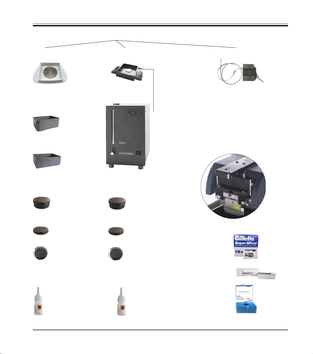
Attachments on dovetail receptacle
3. Instrument Characteristics
Ice bath
Buffer tray
Buffer tray,
plastic
Buffer tray,
metal
Specimen plate
for specimens of
1 cm in height
for specimens of
2 cm in height
Directional
Double-walled buffer tray
Minichiller
(circulating cooler)
Specimen plate
for specimens of
1 cm in height
for specimens of
2 cm in height
Directional
VibroCheck
Fig. 9
Blades for the blade holder
Razor blade
Cyanoacrylate
adhesive
Cyanoacrylate
adhesive
Leica VT1200 and VT1200 S – Microtome
Injector blade
Sapphire blade
11
3. Instrument Characteristics
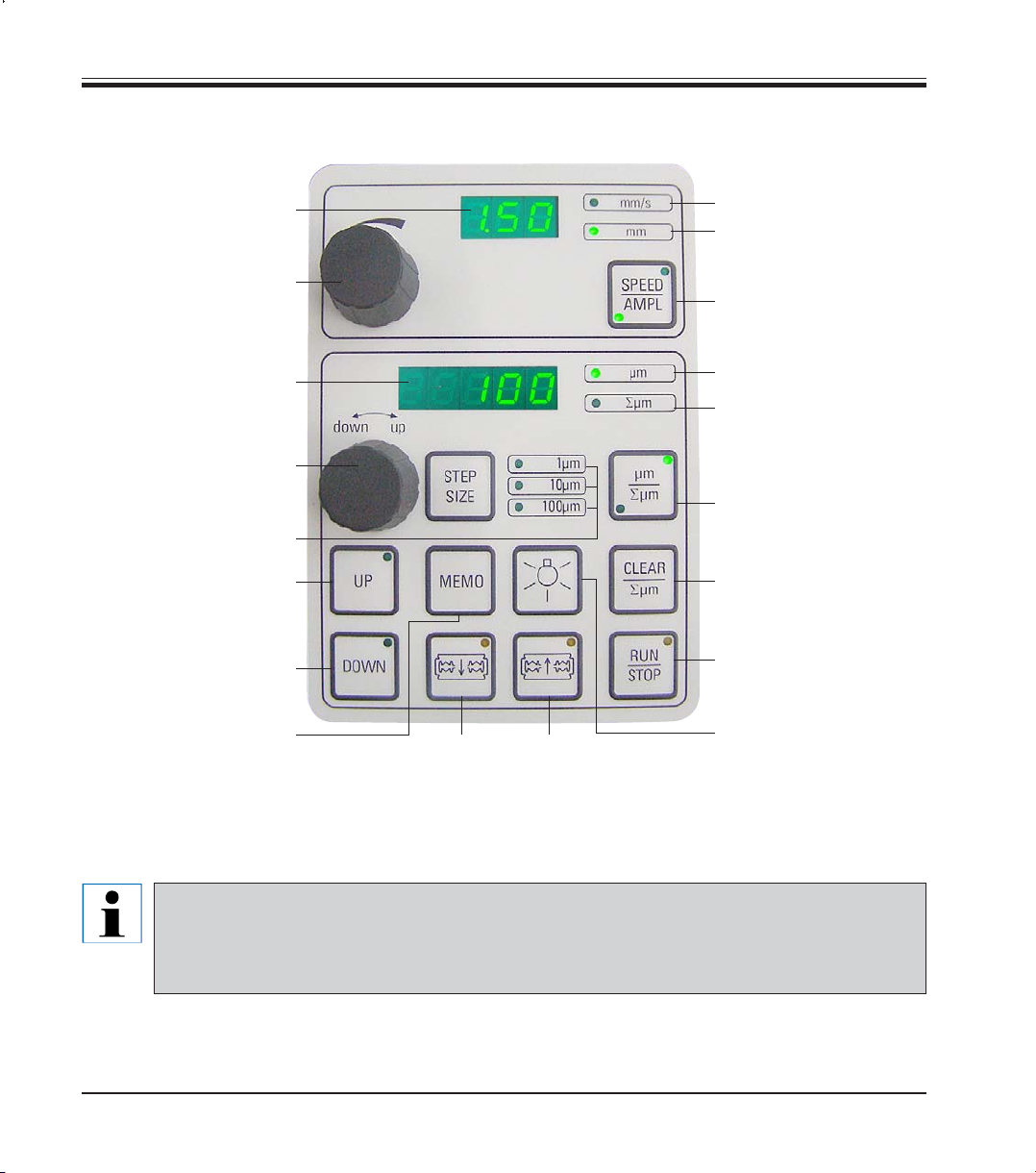
3.3 VT1200 Control Panel
LED display for
blade feed rate and
amplitude
Setting dial 1, for blade
feed rate and amplitude
LED display for
section thickness and
section thickness addition
Setting dial 2, for
section thickness and
moving the specimen
vertically
Selects the step size
in 1μm,10μm or
Quickly moves the speci-
men upwards (press the
button until the desired
position is reached)
Quickly moves the speci-
men downwards (press
once to adjust to the lowest
Press this button
(for approx. 3 sec.) to save a
frequently used feed value
(pressing it more than once
feeds by the saved section
thickness multiple times)
100μm
increments
position)
Moves the blade
towards the specimen
Caution: Press the button until the desired
position is reached. When the end position is
reached, the LED lights up.
LED for feed rate
LED on, for enabled
1
2
Moves the blade away
from the specimen
amplitude adjustment
Toggles between SPEED
(blade feed rate) and
AMPL (amplitude)
Section thickness
Sets the current specimen
position between 0 (lower)
and 20,000μm (upper) or –
after zero, totals the
section thicknesses
Pressing this button toggles
between μm and ∑μm
(actively illuminated)
Resets the section
thickness addition
display ∑μm to zero
Immediately starts or stops
the sectioning process
ON/OFF lamp
Fig. 10
12
The Leica VT1200 is a semiautomatic microtome with a vibrating blade. Before each cut,
a manual feed to the desired section thickness must be carried out using the setting dial for
section thickness. The VT1200 does not include an automatic specimen retraction; however,
retraction can be performed manually.
Operating Manual V1.1 – 05/2007

3.3.1 VT1200S Control Panel
Sets the blade feed rate.
Select the values using
setting dial 1.
Setting dial 1, for blade
feed rate (SPEED),
AMPLitude or section
thickness for automatic
mode (AUTOFEED)
Sets the amplitude.
Select the values
using setting dial 1.
3. Instrument Characteristics
Possible in automatic
sectioning mode only.
Select the desired section
thickness for the automatic
feed using setting dial 1.
ON/OFF lamp
Setting dial 2, for
section thickness and
moving the specimens
vertically
Selects the step size
in 1 μm, 10μm or
1st cutting window edge,
LED illuminates when the
window edge is set.
Moves the specimen
upwards (as long as the
button is pressed). When
the uppermost position is
reached, the LED lights up.
2nd cutting window edge,
LED illuminates when the
window edge is set.
Fig. 11
Toggles between automatic (AUTO) and
semiautomatic (MAN) sectioning mode
The Leica VT1200 S is a fully automatic microtome with a vibrating blade. It can be operated in automatic
as well as semiautomatic sectioning mode.
In semiautomatic sectioning mode, a manual feed to the desired section thickness must be carried out before each cut. There is no automatic specimen retraction in this mode; however, retraction can be performed manually.
In automatic mode, an automatic feed (AUTO FEED) to the selected section thickness is carried out before
each cut, and the specimen is lowered to the desired retraction value after each cut to prevent the specimen surface and the blade from coming into contact while the blade is being retracted.
100μm
increments
Moves the speci-
men into the lowest
position, (LED is
illuminated when
the lowest position
is reached)
Moves the
towards the
specimen
Caution: Press the button
until the desired position is
reached. When the end
position is reached, the LED
lights up.
blade
Moves the
blade away
from the
specimen
Toggles in and out of the
menu. Memory for 8 parameter sets.
Sets the section thickness
addition display ∑μm to "0".
Interrupts the sectioning
process in automatic mode.
Pressing the button again
reactivates the sectioning
process.
Starts or stops the sectioning
process. In semiautomatic
mode, the sectioning process
stops immediately; in automatic
mode, the sectioning process
is finished completely.
Toggling between single
stroke (SINGLE) and continuous stroke (CONT) in automatic
mode is possible; in semiautomatic mode, only single stroke
(SINGLE) is possible.
Leica VT1200 and VT1200 S – Microtome
13

4. Installation
4.1 Standard Scope of Delivery for the VT1200
VT1200 basic instrument .................................................................... 0481 42065
1 control panel ..................................................................................... 0481 43395
1 toolset:
- 1 Allen key, size 3.0 ..................................................................... 0194 04764
- 1 Allen key, size 6.0 ..................................................................... 0222 04141
- 1 cryo-manipulator...................................................................... 0462 28930
- 1 replacement fuse T 1A ............................................................ 6943 01000
1 set of power cables:
- 1 power cable "D" ........................................................................ 0411 13558
- 1 power cable "USA-C-J" ........................................................... 0411 13559
- 1 power cable "UK" ST/BU F-5A ................................................ 0411 27822
1 dust cover (basic instrument), small ............................................. 0212 43742
1 bottle of cyanoacrylate adhesive, contents 10 gr. ..................... 0371 27414
1 Operating Manual for Leica VT1200/VT1200S ............................. 0702 37107
VT1200 configuration........................................................................... 912000001
The above scope of delivery,
plus:
Ice bath, complete .............................................................................. 0481 42010
Buffer tray, (metal) complete ............................................................ 0481 42084
VT blades (10x10 Gillette) .................................................................. 0205 42056
14
When ordering additional accessories, compare the parts received
with the parts ordered. If the parts received do not match your
order, contact the sales company responsible for your order immediately.
Operating Manual V1.1 – 05/2007

4.1.1 Standard Scope of Delivery for the VT1200S
VT1200S basic instrument ................................................................. 0481 42066
1 control panel ..................................................................................... 0481 43396
1 toolset:
- 1 Allen key, size 3.0 ..................................................................... 0194 04764
- 1 Allen key, size 6.0 ..................................................................... 0222 04141
- 1 cryo-manipulator...................................................................... 0462 28930
- 1 replacement fuse T 1A ............................................................ 6943 01000
1 set of power cables:
- 1 power cable "D" ........................................................................ 0411 13558
- 1 power cable "USA-C-J" ........................................................... 0411 13559
- 1 power cable "UK" ST/BU F-5A ................................................ 0411 27822
1 dust cover (basic instrument), small ............................................. 0212 43742
1 bottle of cyanoacrylate adhesive, contents 10 gr. ..................... 0371 27414
1 Operating Manual for Leica VT1200/VT1200S ............................. 0702 37107
VT1200S configuration ........................................................................ 91200S001
The above scope of delivery,
plus:
Ice bath, complete .............................................................................. 0481 42010
Buffer tray, (metal) complete ............................................................ 0481 42084
VT blades (10x10 Gillette) .................................................................. 0205 42056
4. Installation
Leica VT1200 and VT1200 S – Microtome
When ordering additional accessories, compare the parts received
with the parts ordered. If the parts received do not match your
order, contact the sales company responsible for your order immediately.
15
4. Installation
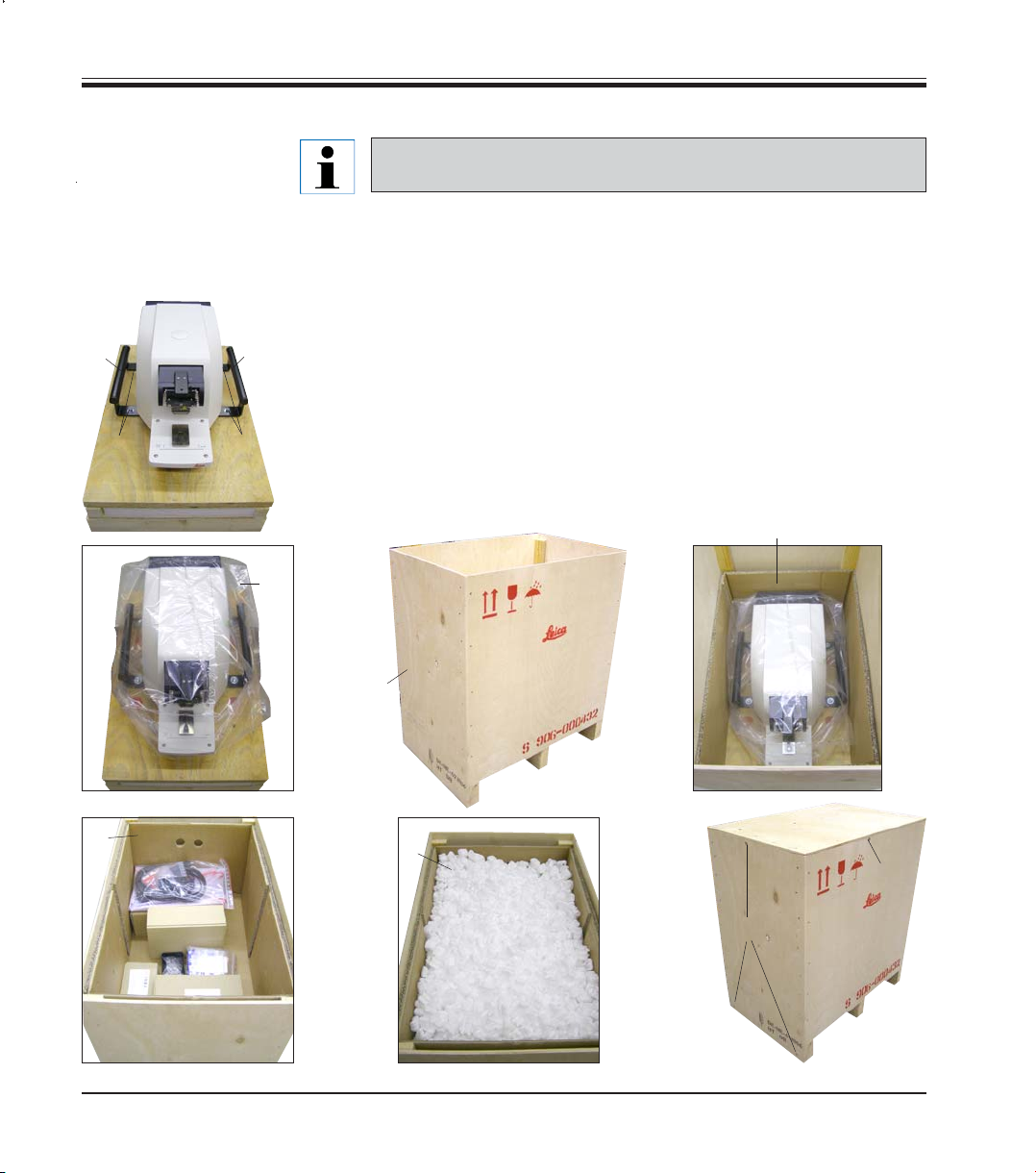
4.2 Packing and Setting up the Instrument
Ensure that the instrument is standing on a work surface that is as free
of vibrations as possible.
Before each transport, the handles must be screwed onto the instrument using the
provided screws (see p. 17, Fig. 13). Check to ensure that the handles are firmly in
place and will hold reliably!
Packing the instrument
1. Have 2 people grab the instrument by the transport handles (1), place it
1
2
1
2
on the wooden pallet and screw it to the pallet using the 4 size 6 hexagon-head screws (2).
2. Pull the transparent protective hood (3) over the instrument. Place the
wooden box (4) on the baseplate. Insert the inner carton ring (5).
3. Insert the accessory box (6 – contains accessories) and fill it with packing material (7).
4. Attach the cover (8) and screw it into place using 8 Phillips screws (9).
3
5
16
➜
4
6
7
➜
➜
8
➜
Operating Manual V1.1 – 05/2007
9
9
Fig. 12
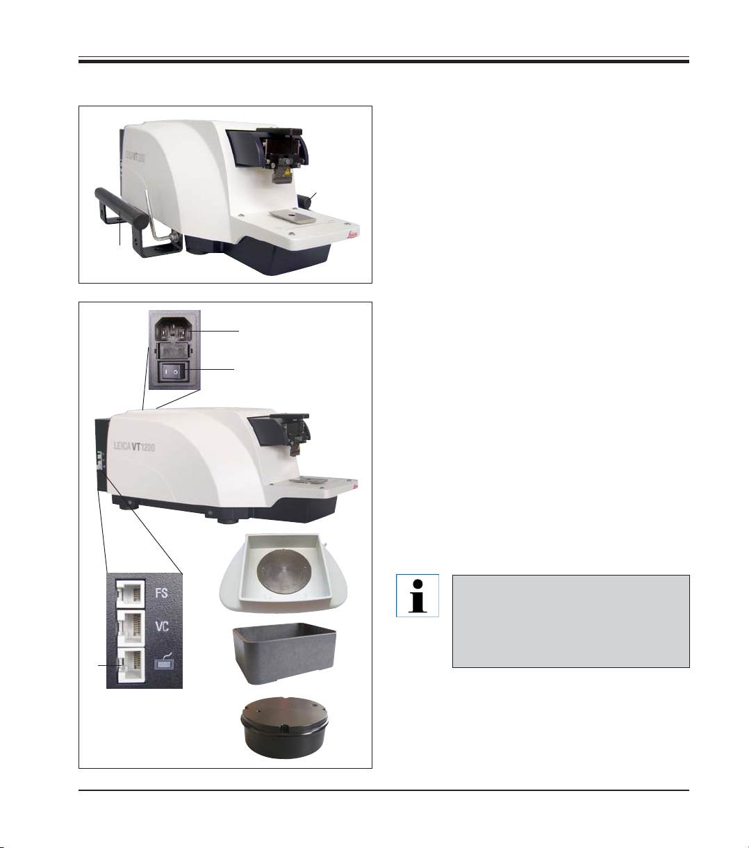
4.3 Before Commissioning the Instrument
1
1
Fig. 13
2
7 (AN)
4
4. Installation
Once the instrument is in its final location, unscrew
the transport handles (1) from the instrument using the size 6 Allen key provided and store them,
along with the screws, in a safe place.
1. Set the power switch (7) on the right side of
the instrument to OFF (❍).
2. Make sure that the power cable connection
in the power socket (2) on the right side of the
instrument is correct.
3. Connect the control panel to the socket (3).
4. Install the ice bath (4).
5. Install the buffer tray (5).
6. Install any optional accessories, such as the
magnifier, microscope, foot switch, etc. according to p. 49.
7. Use the power switch (7) to switch on the instrument.
3
Fig. 14
Leica VT1200 and VT1200 S – Microtome
To make it easier to insert the specimen, adjust the specimen receptacle
to its lowest position, and adjust the
5
6
blade holder to its rearmost position
during the first reference run.
17

5. Working with the Instrument
5.1 Description of the Typical Application
The Leica VT1200 / VT1200S is a microtome with a vibrating blade and is
predominately used for sectioning fixed and unfixed specimens during neurological research.
• To simplify the process of inserting the specimen, you can quickly move the specimen
receptacle to the lowest position by pressing
the DOWN button.
• To prepare high-quality sections, especially
for unfixed tissue, Leica suggests using the
optional VibroCheck measuring instrument to
determine the height amplitude of the blade
after each blade change, and then to minimize
it using the setting screw on the blade holder.
To perform the aforementioned process, install the VibroCheck instrument (see p. 36 for
the VT1200 or p. 38 for the VT1200S), install
the blade and adjust the clearance angle to
the desired position. Then take the measurement and make the appropriate adjustments
to the placement of the blade holder.
Remove the VibroCheck according to the instructions, and turn the blade 90° toward the
top to ensure that the ice bath and buffer tray
can be installed safely.
• Insert the buffer tray into the ice bath and
cover it with the lid. Fill the ice bath with
crushed ice.
• Remove the cover and fill the buffer tray with
pre-cooled physiological buffer.
• Push the ice bath and buffer tray onto the
dovetail guide and clamp them down.
• Use cyanoacrylate adhesive to adhere the
specimen to the specimen plate and use a
manipulator to place it in the buffer tray.
Insert the hose for gassing the buffer into the
hose clamp.
• Use the UP button to lift the specimen to
the sectioning level of the blade quickly. Fineadjusting the blade-to-specimen proximity can
be performed using the desired step size 1, 10
or 100μm.
• Advance the blade toward the specimen using the "Blade forward" key.
• After sectioning the specimen, use the setting
dial to feed to the desired section thickness
using the selected step size (1, 10 or 100μm).
This raises the specimen receptacle to the
desired value.
• Start the sectioning process by pressing the
RUN/STOP key. The process can be stopped
again by pressing this key after the cut has
been completed. Use the "Blade back" key
to move the blade in front of the specimen.
Select the section thickness for the next cut
and start the sectioning process again.
• After completing the sectioning process,
remove the blade, dispose of the specimen
receptacle by pushing the DOWN key into its
lowest position, and unclamp, empty and clean
out the ice bath and buffer tray.
18
Operating Manual V1.1 – 05/2007
 Loading...