

Page 1
Instructions for Use
VT1200 / VT1200 S
Vibrating-blade
microtome
Leica VT1200/VT1200 S V 1.4 RevC, English - 09/2013
Order No. 14 0481 80101 RevC
Always keep this manual with the instrument.
Read carefully before working with the instrument.
Page 2

Page 3

Note
The information, numerical data, notes and value
judgments contained in this manual represent
the current state of scientific knowledge and
state-of-the-art technology as we understand it
following thorough investigation in this field. We
are under no obligation to update the present
manual periodically and on an ongoing basis according to the latest technical developments, nor
to provide our customers with additional copies,
updates etc. of this manual.
To the extent permitted in accordance with
the national legal system as applicable in each
individual case, we shall not be held liable for
erroneous statements, drawings, technical illustrations etc. contained in this manual. In particular, no liability whatsoever is accepted for any
financial loss or consequential damage caused
by or related to compliance with statements or
other information in this manual.
Statements, drawings, illustrations and other
information as regards contents or technical
details of the present Instructions for Use are not
to be considered as warranted characteristics of
our products.
These are determined only by the contract
provisions agreed between ourselves and our
customers.
Leica reserves the right to change technical
specifications, as well as manufacturing processes, without prior notice. Only in this way is
it possible to continuously improve the technology and manufacturing techniques used in our
products.
This document is protected under copyright laws.
Any copyrights of this document are retained by
Leica Biosystems Nussloch GmbH.
Any reproduction of text and illustrations (or
of any parts thereof) by means of print, photocopy, microfiche, web cam or other methods
– including any electronic systems and media
– requires express prior permission in writing by
Leica Biosystems Nussloch GmbH.
For the instrument serial number and year of
manufacture, please refer to the nameplate on
the back of the instrument.
© Leica Biosystems Nussloch GmbH
Leica Biosystems Nussloch GmbH
Heidelberger Str. 17-19
D-69226 Nussloch
Germany
Phone: +49 62 24 143-0
Fax: +49 62 24 143-268
Internet: http://www.LeicaBiosystems.com
Assembly contracted by Leica Microsystems Ltd. Shanghai
Leica VT1200 / VT1200 S
1
Page 4

Contents
1 Important Information ................................................................................................................4
1.1 Symbols in the text and their meanings .................................................................................... 4
1.2 Qualification of personnel ........................................................................................................... 5
1.3 Intended use/improper use ......................................................................................................... 5
2. Safety ............................................................................................................................................6
2.1 General safety notes .................................................................................................................... 6
2.2 Warnings ........................................................................................................................................ 6
2.3 Transport, unpacking and setting up......................................................................................... 7
3. Instrument characteristics ........................................................................................................8
3.1 Technical data for the VT1200 ................................................................................................... 8
3.1.1 Technical data for the VT1200 S ................................................................................................ 9
3.2 General overview – VT1200/VT1200 S ..................................................................................... 10
3.3 VT1200 Control Panel ................................................................................................................. 12
3.3.1 VT1200 S control panel .............................................................................................................. 13
4. Installation .................................................................................................................................14
4.1 Standard scope of delivery for the VT1200............................................................................. 14
4.1.1 Standard scope of delivery for the VT1200 S ......................................................................... 15
4.2 Packing and setting up the instrument ................................................................................... 16
4.3 Before commissioning the instrument .................................................................................... 17
5. Working with the Instrument ..................................................................................................18
5.1 Description of the typical application ..................................................................................... 18
5.2 Control elements on the VT1200 control panel ...................................................................... 19
5.2.1 Moving the specimen receptacle vertically........................................................................... 19
5.2.2 Fine-adjusting the blade-to-specimen proximity and feeding to the section thickness ..... 20
5.2.3 Moving the blade ........................................................................................................................ 20
5.2.4 Selecting the sectioning parameters ...................................................................................... 21
5.3 Control elements on the VT1200 S control panel .................................................................. 22
5.4 Installing the accessories ......................................................................................................... 32
5.4.1 Installing the ice tray and buffer tray ...................................................................................... 32
5.4.2 Installing the double-walled buffer tray.................................................................................. 33
5.4.3 Preparing a specimen ................................................................................................................ 33
5.4.4 Installing and removing the blade holder ............................................................................... 34
5.4.5 Inserting the blade ...................................................................................................................... 35
5.4.6 Adjusting the clearance angle ................................................................................................. 35
5.5 Routine daily maintenance and switching off the instrument – VT1200/VT1200 S .......... 36
2
Instructions for Use V 1.4 RevC – 09/2013
Page 5

Contents
6. Operating the VibroCheck ...................................................................................................... 37
6.1 Using the VibroCheck with the VT1200 ................................................................................... 37
6.2 Using the VibroCheck with the VT1200 S ................................................................................ 39
7. Malfunctions: Meaning and Troubleshooting .................................................................... 41
7.1 Error messages and troubleshooting ...................................................................................... 41
7.2 Replacing the main fuse ............................................................................................................ 46
8. Cleaning and Maintenance .................................................................................................... 47
8.1 Cleaning the instrument............................................................................................................. 47
9. Ordering Information for Optional Accessories, Consumables and Spare Parts .........48
9.1 Extension accessories for standard specimens .................................................................. 49
9.1.1 Buffer trays .................................................................................................................................. 49
9.1.2 Specimen plate ........................................................................................................................... 50
9.1.3 VibroCheck ................................................................................................................................... 51
9.1.4 Blades ........................................................................................................................................... 52
9.1.5 Microscope, assembly ............................................................................................................... 52
9.1.6 Magnifier, assembly ................................................................................................................... 52
9.1.7 Installing the magnifier support or microscope support .................................................... 53
9.1.8 Fiber-optic illumination, cold light source .............................................................................. 54
9.1.9 Cyanoacrylate adhesive ............................................................................................................ 55
9.1.10 Foot switch .................................................................................................................................. 55
9.1.11 Julabo FL300 – recirculating cooler/chiller ............................................................................ 55
10. Warranty and Service ..............................................................................................................56
11. Decontamination Certificate (Master) ..................................................................................58
Leica VT1200 / VT1200 S
3
Page 6
1 Important Information
1.1 Symbols in the text and their meanings
Warnings
appear in a gray box and are marked by
a warning triangle .
Useful tips,
i.e. important user information, appear
in a gray box and are marked by an .
(5)
(Fig. 5)
Numbers in parentheses refer to item
numbers in illustrations or to the illustrations themselves.
Manufacturer
Date of Manufacture
The CE labeling shows that the product
corresponds to one or more applicable
European directives.
Observe the Instructions for Use
Order No.
Serial number
Environmental protection symbol of
the China RoHS directive.
The number in the symbol indicates
the "Environment-friendly Use Period"
of the product in years.
The symbol is used if a substance
restricted in China is used in excess
of the maximum permitted limit.
The CSA test mark means that a
product has been tested and fulfills
the applicable safety and/or performance standards, including the
relevant standards defined or administered by the American National
Standards Institute (ANSI), Underwriters Laboratories (UL), the Canadian Standards Association (CSA),
the National Sanitation Foundation
International (NSF) and others.
Symbol for labeling electrical and
electronic equipment in accordance
with Section 7 of the German Electrical and Electronic Equipment Act
(ElektroG).
ElektroG is the law on the bringing
into circulation, return and environmentally compatible disposal of electrical and electronic equipment.
Instrument
model:
4
All information provided in these Instructions for Use applies only to the instrument
type indicated on the title page.
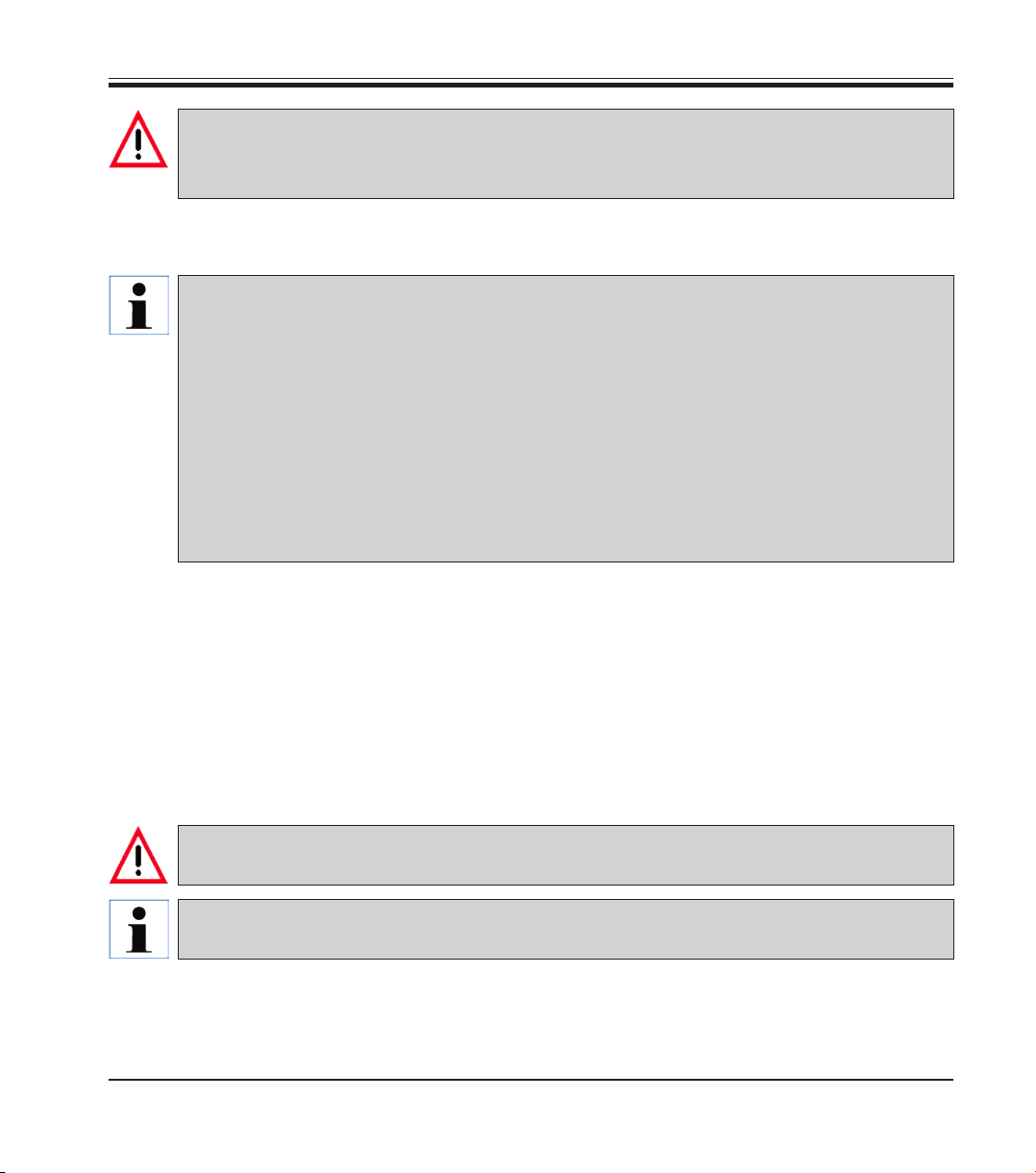
A nameplate is attached to the rear side of the instrument. The series and REF numbers are attached to a separate label (Fig. 1a) on the right side of the instrument.
Fig. 1 and 1a are provided as an example only and show a valid nameplate for this
instrument.
Instructions for Use V 1.4 RevC – 09/2013
Page 7
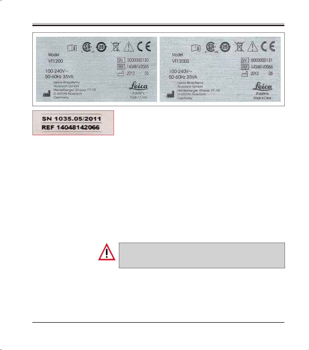
Fig. 1a
1.2 Qualification of personnel
The Leica VT1200 and the VT1200 S may be operated by trained laboratory
personnel only.
All laboratory personnel designated to operate this instrument must read
these Instructions for Use carefully and must be familiar with all technical
features of the instrument before attempting to operate it.
1. Important Information
Fig. 1
1.3 Intended use/improper use
The Leica VT1200 and VT1200 S are used for sectioning in the fields of medicine, biology and industry, and are especially designed for sectioning fixed
or unfixed fresh tissue in buffer.
The instrument must be used exclusively according to the instructions contained in these Instructions for Use.
Any other use of the instrument is considered improper.
Leica VT1200 / VT1200 S
The VT1200/VT1200 S may be used for research purposes only. Sections made using the VT1200/VT1200 S must NOT be used for diagnostics.
5
Page 8

2. Safety
These Instructions for Use includes important information related to the
operating safety and maintenance of the instrument.
The Operating Manual is an important part of the product, and must be
read carefully prior to startup and use and must always be kept near the
instrument.
If additional requirements on accident prevention and environmental protection apply in the country of operation, these Instructions for Use must
be supplemented by appropriate instructions to ensure compliance with
such requirements.
Make sure to read all of these Instructions for Use before you work on or
operate the instrument.
2.1 General safety notes
These instruments have been built and tested in accordance with the safety
regulations for electrical measuring, control, regulating and laboratory
devices.
In order to maintain this condition and to ensure safe operation, the user
must follow the instructions and warnings contained in this operating manual.
2.2 Warnings
6
The current EC Declarations of Conformity can be found on the Internet:
www.LeicaBiosystems.com
The safety devices installed in this instrument by the manufacturer only
constitute the basis for accident prevention. Operating the instrument safely
is, above all, the responsibility of the owner, as well as the designated personnel who operate, service or clean the instrument.
To ensure trouble-free operation of the instrument, make sure to comply
with the following instructions and warnings.
Instructions for Use V 1.4 RevC – 09/2013
Page 9
• Extremely sharp blades pose risk of injury when touched!
• Fresh tissue poses risk of infection!
• Fire hazard from uncovered magnifier! Cover the magnifier during work breaks!
Proper handling
Always be exceptionally careful when handling the blades!
Do not leave open blades lying around after removal.
Always make sure to handle the blade in a way that will not cause you injury.
All appropriate safety precautions must be met to avoid the risk of infection.
Wearing safety gloves, a mask and safety goggles—in accordance with the "Working with Sub-
stances that Pose a Health Risk" guidelines—is absolutely mandatory.
The instrument may be opened by authorized service personnel only.
Always disconnect the power plug before opening the instrument.
Always switch off the instrument using the power switch and disconnect the power plug before
replacing the fuse. The use of fuses other than those installed at the factory is not permitted.
2.3 Transport, unpacking and setting up
2. Safety
The instrument must be set up so that the main power switch on its right side (item 7 in Fig. 14) is
easily accessible at any time.
Because the weight of the instrument is approx. 56 kg, carrying the instrument requires 2 persons
(1 carrying handle per person).
Leica VT1200 / VT1200 S
• Whenunpackingtheinstrument,comparethepartsreceivedwiththe
parts ordered. If the parts received do not match your order, contact the
sales company responsible for your order immediately.
• Beforeconnectingtothepowersupplysystem,pleaseobserve"Technical Data"!
• Neverconnecttheinstrumenttoapowersocketthatdoesnothavea
protective conductor terminal.
7
Page 10

3. Instrument characteristics
3.1 Technical data for the VT1200
General data:
Sectioning frequency (±10 %) ........................................................................................................... 85 Hz (± 10 %)
Amplitude.................................................................................................... from 0 - 3 mm, in 0.05 mm increments
Sectioning speed (± 10 %) ................................................................................................................ 0.01 - 1.5 mm/s
Return speed (± 10 %) ..................................................................................................................................2.5 mm/s
Total vertical specimen stroke .................................................................................................20 mm (motorized)
Cutting range ..............................................................................................................................45 mm (adjustable)
Maximum specimen size:
With standard blade holder ............................................................................................................. 33 x 50 mm
Specimen orientation, rotating .................................................................................................................... 360°
Specimen plate, swiveling ....................................................................................................................... 0 - 10°
Section thickness adjustment .................................................................................. manual, in 1 µm increments
Ambient conditions:
Operating temperature range: ........................................................................................... min. 10 °C - max. 35 °C
Relative humidity: ....................................................................................................................................... max. 60 %
Storage temperature: ................................................................................................................................... 5 - 55 °C
Storage humidity: ............................................................................................................................................. < 60 %
Height: ........................................................................................................................ up to 2000 m above sea level
Electrical data:
Rated voltage range (± 10 %): ....................................................................................................................... 100 V - 240 V
Nominal frequency (±10 %): .................................................................................................................................. 50/60 Hz
Power consumption: ...................................................................................................................................................35 VA
Protective class: ...................................................................................................................................................................I
Power fuse: ...................................................................................................................................................... T 1 A L 250 V
Pollution degree: ..................................................................................................................................................................2
Overvoltage category: ....................................................................................................................................................... II
Electrical overload protection: ..................................................................................................................................... Yes
Internal current limit for the electronics: ................................................................................................................... Yes
Dimensions:
L x W x H: ............................................................................................................................... 600 mm x 250 mm x 230 mm
Height with magnifier support ............................................................................................ 600 mm x 250 mm x 320 mm
Height with microscope: ..................................................................................................... 600 mm x 250 mm x 490 mm
L x W x H control unit (when the bases are folded in): ................................................... 165 mm x 120 mm x 72 mm
Weight:
Without magnifier support and control unit .............................................................................................................56 kg
VT1200 control unit .........................................................................................................................................................1 kg
Magnifier support ...........................................................................................................................................................2 kg
Microscope support with stereomicroscope ............................................................................................................4 kg
8
Instructions for Use V 1.4 RevC – 09/2013
Page 11

3. Instrument Characteristics
3.1.1 Technical data for the VT1200 S
General data:
Sectioning frequency (± 10 %): ...................................................................................................................85 Hz (± 10 %)
Amplitude: ....................................................................................................... from 0 - 3 mm, in increments of 0.05 mm
Sectioning speed (± 10 %): ........................................................................................................................0.01 - 1.5 mm/s
Return speed (± 10 %): .................................................................................... 1.0 - 5 mm/s, in increments of 0.5 mm/s
Total vertical specimen stroke: ......................................................................................................... 20 mm (motorized)
Sectioning range: ..................................................................................................................................................... 45 mm
Sectioning window: .................................................................................................................................. 0.5 mm - 45 mm
Specimen retraction: .............................................................................. 0 - 100 µm (adjustable; can be deactivated)
Maximum specimen size:
with standard blade holder: ..................................................................................................................... 33 x 50 mm
Specimen orientation, rotating: ........................................................................................................................... 360°
Specimen plate, swiveling: ...............................................................................................................................0 - 10°
Sectioning thickness setting: ............................................manual in 1 µm increments or automatic max. 1000 µm
Ambient conditions:
Operating temperature range: .....................................................................................................min. 10 °C - max. 35 °C
Relative humidity: ............................................................................................................................................... max. 60 %
Storage temperature: .............................................................................................................................................5 - 55 °C
Storage humidity: .......................................................................................................................................................< 60 %
Height: .................................................................................................................................up to 2000 m above sea level
Electrical data:
Rated voltage range (± 10 %): ...................................................................................................................... 100 V - 240 V
Nominal frequency (± 10 %): ................................................................................................................................ 50/60 Hz
Power consumption: ..................................................................................................................................................35 VA
Protective class: ..................................................................................................................................................................I
Power fuse: ..................................................................................................................................................... T 1 A L 250 V
Pollution degree: .................................................................................................................................................................2
Overvoltage category: ...................................................................................................................................................... II
Electrical overload protection: .................................................................................................................................... Yes
Internal current limit for the electronics: .................................................................................................................. Yes
Dimensions:
L x W x H: .............................................................................................................................. 600 mm x 250 mm x 230 mm
Height with magnifier: ......................................................................................................... 600 mm x 250 mm x 320 mm
Height with microscope: .................................................................................................... 600 mm x 250 mm x 490 mm
Control unit (when the bases are folded in): ..................................................................... 190 mm x 150 mm x 72 mm
Weight:
Without magnifier support and control unit: ...........................................................................................................56 kg
VT1200 S control unit: ...................................................................................................................................................1 kg
Magnifier support: .........................................................................................................................................................2 kg
Microscope support with stereomicroscope: ..........................................................................................................4 kg
Leica VT1200 / VT1200 S
9
Page 12
3. Instrument characteristics
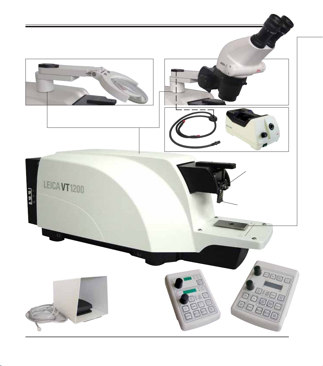
3.2 General overview – VT1200/VT1200 S
Fig. 3, Magnifier
Fiber
optic
light guide
Cold light
source
Fig. 4, Microscope
Fig. 5
Cutting head
Fig. 2, Basic instrument
10
Fig. 6,
Foot switch
Blade holder
Fig. 8,
Control panelm
VT1200 Smm
Fig. 7,
VT1200 control
panel
Instructions for Use V 1.4 RevC – 09/2013
Page 13
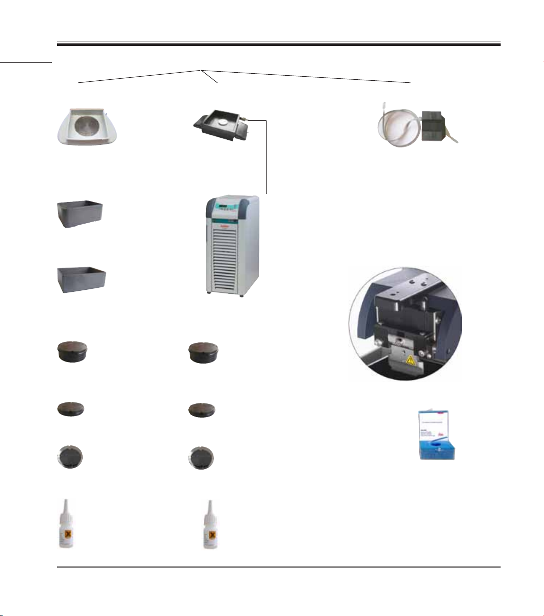
Attachments on dovetail receptacle
3. Instrument Characteristics
Ice tray
Buffer tray
Buffer tray,
plastic
Buffer tray,
metal
Specimen plate
for specimens 1 c m
in height
for specimens 2 cm
in height
Double-walled buffer tray
Julabo FL300
(recirculating
cooler/chiller)
Specimen plate
for specimens 1 c m
in height
for specimens 2 cm
in height
VibroCheck
Fig. 9
Blades for the blade holder
Sapphire blade
Directional
Cyanoacrylate adhesive
Leica VT1200 / VT1200 S
Directional
Cyanoacrylate adhesive
11
Page 14
3. Instrument characteristics
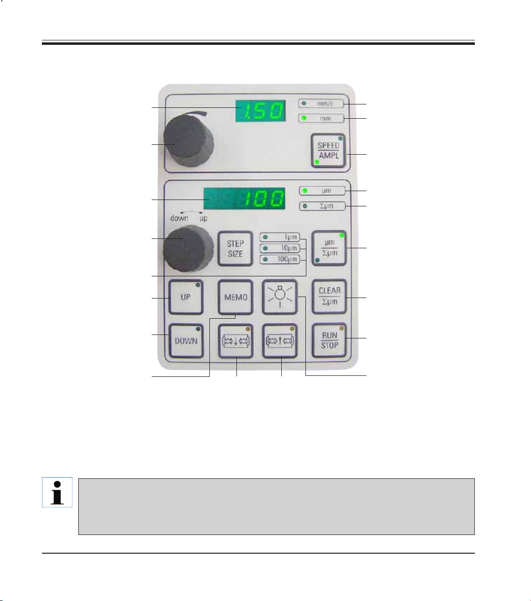
3.3 VT1200 Control Panel
LED display for blade feed
rate and amplitude
Setting dial 1, for blade feed
rate and amplitude
LED display for section
thickness and
section thickness totalizing
Setting dial 2, for section
thickness and moving the
specimens vertically
Selection of the step size,
1 µm,10 µm or
Quickly moves the speci-
men upwards (press the
button until the desired
Quickly moves the specimen
downwards (press once to
adjust to the lowest position)
(for approx. 3 sec.) to save a
frequently used feed value
(pressing it more than once
feeds by the saved section
thickness multiple times).
100 µm steps
position is reached)
Press this button
Moves the blade to-
wards the specimen
Caution: Keep it pressed down until the desired
position is reached. When the end position is
reached, the LED lights up.
LED for feed rate
LED on, for enabled ampli-
1
2
Moves the blade away
from the specimen
tude adjustment
Toggles between SPEED (blade
feed rate) and AMPL (amplitude)
Section thickness
Sets the current specimen
position between 0 (lower) and
20,000 µm (upper) or - after zero,
totals the section thicknesses
Pressing this button toggles
between µm and ∑µm (actively illuminated).
Resets the totalized section
thickness display ∑µm to zero.
Immediately starts or stops
the sectioning process
ON/OFF lamp
Fig. 10
12
The Leica VT1200 is a semiautomatic microtome with a vibrating blade. Before each cut, a manual feed to the desired section thickness must be carried out using the setting dial for section
thickness. The VT1200 does not include an automatic specimen retraction; however, retraction
can be performed manually.
Instructions for Use V 1.4 RevC – 09/2013
Page 15
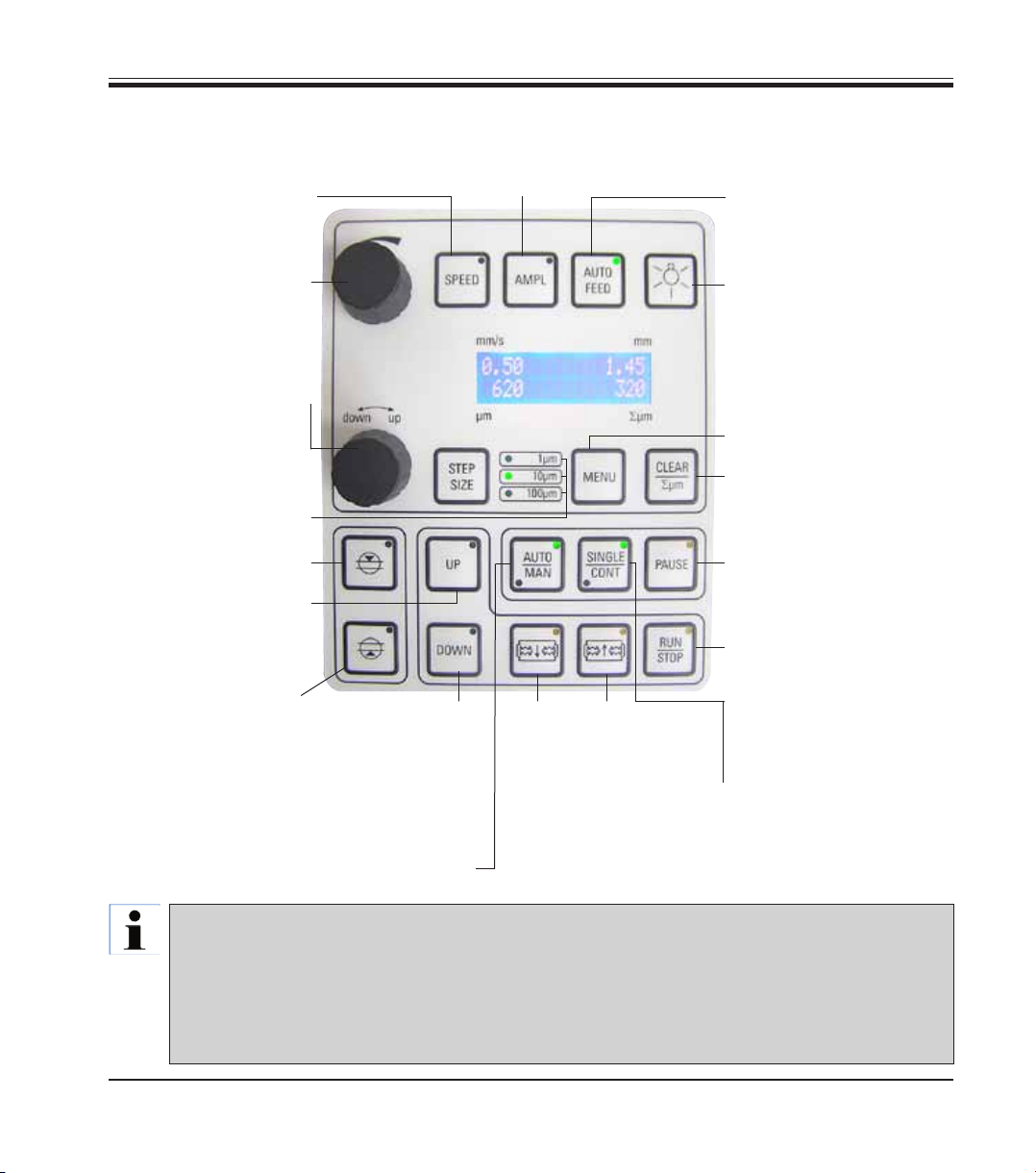
3.3.1 VT1200 S control panel
Sets the blade feed rate.
Select the values using set-
ting dial 1.
Setting dial 1, for blade
feed rate (SPEED),
AMPLitude or section
thickness for automatic
mode (AUTO FEED)
Sets the amplitude.
Select the values using
setting dial 1.
3. Instrument Characteristics
Possible in automatic sectioning
mode only. Select the desired section thickness for the automatic
feed using setting dial 1.
ON/OFF lamp
Setting dial 2, for section
thickness and moving the
specimens vertically
Selection of the step size,
1 µm, 10 µm or 100 µm steps
First cutting window edge,
LED illuminates when the
window edge is set
Moves the specimen up-
wards (as long as the button
is pressed). When the up-
permost position is reached,
the LED lights up.
Second cutting window
edge, LED illuminates when
the window edge is set
Fig. 11
Toggles between automatic (AUTO) and
semiautomatic (MAN) sectioning mode
The Leica VT1200 S is a fully automatic microtome with vibrating blade. It can be operated in automatic as well as
semiautomatic sectioning mode.
In semiautomatic sectioning mode, a manual feed to the desired section thickness must be carried out before
each cut. There is no automatic specimen retraction in this mode; however, retraction can be performed manually.
In automatic mode, an automatic feed (AUTO FEED) to the selected section thickness is carried out before each
cut, and the specimen is lowered to the desired retraction value after each cut to prevent the specimen surface
and the blade from coming into contact while the blade is being retracted.
Moves the speci-
men into the lowest
position, (LED is
illuminated when the
lowest position is
reached)
Moves the
blade towards
the specimen
Caution: Keep it pressed
down until the desired position is reached. When the
end position is reached, the
LED lights up.
Moves the blade
away from the
specimen
Toggles in and out of the
menu. Memory for 8 parameter sets.
Sets the totalized section
thickness display åµm to "0".
Interrupts the sectioning
process in automatic mode.
Pressing the button again
reactivates the sectioning
process.
Starts or stops the sectioning process. In semiautomatic
mode, the sectioning process
stops immediately; in automatic
mode, the sectioning process is
finished completely.
Toggling between single
stroke (SINGLE) and continuous stroke (CONT) in automatic
mode is possible. In semiautomatic mode, only single stroke
(SINGLE) is possible.
Leica VT1200 / VT1200 S
13
Page 16

4. Installation
4.1 Standard scope of delivery for the VT1200
VT1200 basic instrument ............................................................... 14 0481 42065
1 control panel ................................................................................ 14 0481 43395
1 toolset:
- 1 Allen key, size 3.0 ................................................................. 14 0194 04764
- 1 Allen key, size 6.0 ................................................................. 14 0222 04141
- 1 cryo-manipulator .................................................................. 14 0462 28930
- 1 replacement fuse T 1 A ....................................................... 14 6943 01000
1 set of power cables:
- 1 power cable "D" .................................................................... 14 0411 13558
- 1 power cable "USA-C-J" ....................................................... 14 0411 13559
- 1 power cable "UK" ST/BU F-5A ............................................ 14 0411 27822
1 dust cover (basic instrument), small ......................................... 14 0212 43742
1 bottle of cyanoacrylate adhesive, contents 10 gr. .................. 14 0371 27414
1 Instructions for Use for Leica VT1200/VT1200 S...................... 14 0481 80101
1 language CD .................................................................................. 14 0481 80200
14
VT1200 configuration ....................................................................... 14 912000001
The above scope of delivery, plus:
Ice tray, assembly ........................................................................... 14 0481 42010
Buffer tray (metal), assembly ........................................................ 14 0481 42084
When ordering additional accessories, compare the parts received
with the parts ordered. If the parts received do not match your order,
contact the sales company responsible for your order immediately.
Instructions for Use V 1.4 RevC – 09/2013
Page 17

4.1.1 Standard scope of delivery for the VT1200 S
VT1200 S basic instrument ............................................................. 14 0481 42066
1 control panel ................................................................................ 14 0481 43396
1 toolset:
- 1 Allen key, size 3.0 ................................................................. 14 0194 04764
- 1 Allen key, size 6.0 ................................................................. 14 0222 04141
- 1 cryo-manipulator .................................................................. 14 0462 28930
- 1 replacement fuse T 1A ........................................................ 14 6943 01000
1 set of power cables:
- 1 power cable "D" .................................................................... 14 0411 13558
- 1 power cable "USA-C-J" ....................................................... 14 0411 13559
- 1 power cable "UK" ST/BU F-5A ............................................ 14 0411 27822
1 dust cover (basic instrument), small ......................................... 14 0212 43742
1 bottle of cyanoacrylate adhesive, contents 10 gr. .................. 14 0371 27414
1 Instructions for Use for Leica VT1200/VT1200 S...................... 14 0481 80101
1 language CD .................................................................................. 14 0481 80200
4. Installation
Leica VT1200 / VT1200 S
VT1200 S configuration ...................................................................14 91200S001
The above scope of delivery, plus:
Ice tray, assembly ........................................................................... 14 0481 42010
Buffer tray (metal), assembly ........................................................ 14 0481 42084
When ordering additional accessories, compare the parts received
with the parts ordered. If the parts received do not match your order,
contact the sales company responsible for your order immediately.
15
Page 18

4. Installation
4.2 Packing and setting up the instrument
Ensure that the instrument is standing on a work surface that is as free
of vibrations as possible.
Before each transport, the handles must be screwed onto the instrument using the
provided screws (see Fig. 13). Check to ensure that the handles are firmly in place
and will hold reliably!
Packing the instrument
1. Have 2 people grab the instrument by the transport handles (1), place it
1
2
1
2
3
on the wooden pallet and screw it to the pallet using the 4 size 6 Allen
screws (2).
2. Pull the transparent protective hood (3) over the instrument. Place the
wooden box (4) on the baseplate. Insert the inner carton ring (5).
3. Insert the accessories box (6 – contains accessories) and fill it with
packing material (7).
4. Attach the cover (8) and screw it into place using 8 Phillips screws (9).
5
16
4
6
7
8
9
Instructions for Use V 1.4 RevC – 09/2013
9
Fig. 12
Page 19
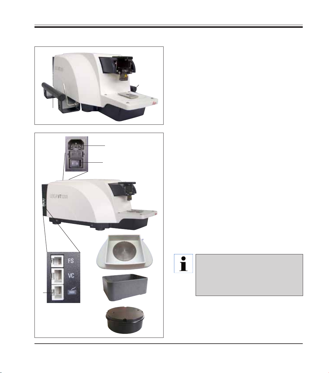
4.3 Before commissioning the instrument
1
1
Fig. 13
2
7 (AN)
4
4. Installation
Once the instrument is in its final location, unscrew the transport handles (1) from the instrument using the size 6 Allen key provided and
store them, along with the screws, in a safe
place.
1. Set the power switch (7) on the right side of
the instrument to OFF ().
2. Make sure the power cable is correctly connected in the power socket (2) on the right side
of the instrument.
3. Connect the control panel to the socket (3).
4. Install the ice tray (4).
5. Install the buffer tray (5).
6. Install any optional. accessories, such as the
magnifier, microscope, foot switch, etc. according to p. 49.
7. Use the power switch (7) to switch on the
instrument.
3
Fig. 14
Leica VT1200 / VT1200 S
To make it easier to insert the specimen, adjust the specimen receptacle to
its lowest position, and adjust the blade
5
6
holder to its rearmost position during
the first reference run.
17
Page 20

5. Working with the Instrument
5.1 Description of the typical application
The Leica VT1200 / VT1200 S is a microtome with a vibrating blade and is
predominately used for sectioning fixed and unfixed specimens during
neurological research.
• Tosimplifytheprocessofinsertingthespecimen, you can quickly move the specimen receptacle to the lowest position by pressing the
DOWN button.
• To preparehigh-quality sections,especially
for unfixed tissue, Leica suggests using the
optional VibroCheck measuring instrument to
determine the height amplitude of the blade
after each blade change, and then to minimize
it using the setting screw on the blade holder.
To perform the aforementioned process, install
the VibroCheck instrument (see p. 37 for the
VT1200 or p. 39 for the VT1200 S), install the
blade and adjust the clearance angle to the
desired position. Then take the measurement
and make the appropriate adjustments to the
placement of the blade holder.
Remove the VibroCheck according to the in-
structions, and turn the blade 90° toward the
top to ensure that the ice tray and buffer tray
can be installed safely.
• Insertthebuffertrayintotheicetrayandcover
it with the lid. Fill the ice tray with crushed ice.
• Removethecoverandfillthebuffertraywith
pre-cooled physiological buffer.
• Pushthe icetray and buffertray onto the
dovetail guide and clamp them down.
• Usecyanoacrylate adhesive toadhere the
specimen to the specimen plate and use a
manipulator to place it in the buffer tray. Insert
the hose for gassing the buffer into the hose
clamp.
• UsetheUP button to lift the specimen to the
sectioning level of the blade quickly. Fineadjusting the blade-to-specimen proximity can
be performed using the desired step size 1, 10
or 100 µm.
• Advancethebladetowardthespecimenusing
the "Blade forward" key.
• Aftersectioningthespecimen,usethesetting
dial to feed to the desired section thickness
using the selected step size (1, 10 or 100 µm).
This raises the specimen receptacle to the
desired value.
• Startthesectioningprocessbypressingthe
RUN/STOP key. The process can be stopped
again by pressing this key after the cut has
been completed. Use the "Blade back" key to
move the blade in front of the specimen. Select
the section thickness for the next cut and start
the sectioning process again.
• Aftercompletingthe sectioning process,
remove the blade, dispose of the specimen
receptacle by pushing the DOWN key into its
lowest position, and unclamp, empty and clean
out the ice tray and buffer tray.
18
Instructions for Use V 1.4 RevC – 09/2013
Page 21

5.2 Control elements on the VT1200 control panel
Caution: To practice the key functions, always make sure there are
no blades installed! Do not install the blades until you are familiar
with all of the key functions.
When the instrument is switched on, to make it easier to insert a specimen,
the specimen receptacle automatically moves into the lowest position (the
LED in the DOWN key lights up) and the blade holder moves into the rear-
Switch on the
instrument.
1 = on 0 = off
most position (the LED in "Blade away" from the specimen lights up).
The parameters last used before switching off the instrument: The blade
feed rate (SPEED), selected amplitude (AMPL) and section thickness saved
by the MEMO key are called up again.
The LED illumination is switched on automatically. You can switch it off
using the ON/OFF key (lamp symbol).
5.2.1 Moving the specimen receptacle vertically
When the DOWN key is pressed, the specimen receptacle automatically
moves quickly into the lowest position. (The LED in the DOWN key lights up
when the lower end position is reached.) The ∑µm display is set to "0". If
the DOWN key is pressed a second time while the specimen receptacle is
moving downwards, the specimen receptacle comes to a stop. The current
position appears on the ∑µm display (lowest position = 0). The ∑µm display
does not change while the specimen receptacle is in motion.
5. Working with the Instrument
Leica VT1200 / VT1200 S
When the UP key is pressed and held, the specimen receptacle moves
quickly upwards into the desired position. After the UP key has been released, the current position of the specimen receptacle appears on the ∑µm
display. If the specimen receptacle reaches the upper end position, the LED
in the UP key lights up (uppermost position = 20,000 µm). The ∑µm display
does not change while the specimen receptacle is in motion.
You can reset the display for the current position of the specimen holder to
zero at any point using the CLEAR /∑µm key. The section thicknesses are
then added in the ∑µm display.
19
Page 22

5. Working with the Instrument
5.2.2 Fine-adjusting the blade-to-specimen proximity and feeding to the section thickness
The rotary knob 2 for moving the specimen receptacle vertically can be
used both for fine-adjusting the blade-to-specimen proximity and for adjusting the desired section thicknesses. The step size: 1, 10 or 100 µm can be
selected by pressing the STEP SIZE key.
Turning the setting dial clockwise carries out the desired feed; turning the
setting dial counterclockwise lowers the specimen (minus sign). The value
appears in the lower display when "µm" is selected. After each sectioning
process has been completed, the µm display is set to zero.
Save a commonly used section thickness by adjusting the setting dial for
the section thickness and pressing the MEMO key for 3 seconds. An audible
signal confirms that the value has been accepted.
Feed to the saved value by quickly pressing the MEMO key. Pressing the
MEMO multiple times feeds to the value multiple times.
Neither negative values nor a section thickness of over 1000 µm are
permitted. If an attempt is made to save impermissible values, an audible warning signal sounds three times and the last (permissible)
value is retained.
5.2.3 Moving the blade
Blade
forward back
20
The "Blade forward" and "Blade back" keys have to be held down until the
desired position is reached. The blade feed rate is 2.5 mm/s. When each end
point has been reached, the corresponding LED lights up in the key.
Instructions for Use V 1.4 RevC – 09/2013
Page 23

5.2.4 Selecting the sectioning parameters
SPEED: Blade feed rate – upper display – LED mm/s. The desired blade feed
rate can be adjusted from 0.01 to 1.5 mm/s using rotary knob 1:
0.01 – 0.1 in 0. 01 mm/s increments,
0.10 – 0.5 in 0.02 mm/s increments,
0.50 – 1.5 in 0.10 mm/s increments.
AMPL: upper display – LED mm: Display of the amplitude in mm:
from 0 - 3 mm in 0.05 mm increments
Starts the sectioning process
Starts the sectioning process using the selected amplitude and blade feed
rate. You can start the sectioning process by pressing the RUN/STOP key
a second time, or you can stop the process immediately by pressing the
"Blade back" or "Blade forward" key. The µm display is then reset to "0".
To start a new sectioning process, use the "Blade back" key to move the
blade to the beginning of the specimen, set the desired section thickness
and restart the sectioning process.
5. Working with the Instrument
Leica VT1200 / VT1200 S
21
Page 24

5. Working with the Instrument
5.3 Control elements on the VT1200 S control panel
The Leica VT1200 S is a fully automatic microtome with a vibrating blade
that can be operated in semiautomatic or automatic sectioning mode.
Key / setting dial Semiautomatic sectioning mode Automatic sectioning mode
Switch on the instrument.
1 = on 0 = off
When the instrument is switched
on, to make it easier to insert a
specimen, the specimen receptacle automatically moves into
the lowest position (the LED in the
DOWN key lights up) and the blade
holder moves into the rearmost
position (the LED in "Blade away"
from the specimen lights up).
If semiautomatic sectioning
mode was selected before the
instrument was last switched
off, the following saved parameters are called up again once it
is switched back on:
• Bladefeedrate(SPEED),
• Selectedamplitude(AMPL)
The LED illumination is switched
on automatically. You can switch
it off using the ON/OFF key.
ditto
• Bladefeedrate(SPEED),
• Selectedamplitude(AMPL)
• Savedsectionthickness(AUTO
FEED)
ditto
22
The LED MAN is active.
semiautomatic sectioning mode
is enabled.
The LED AUTO is active.
The automatic sectioning mode
is enabled.
Instructions for Use V 1.4 RevC – 09/2013
Page 25

5. Working with the Instrument
Key / setting dial Semiautomatic sectioning mode Automatic sectioning mode
Toggling from AUTO to
MAN
In semiautomatic sectioning
mode, before each cut, a manual
feed to the desired section thickness must be carried out using
the setting dial for section thickness.
There is no automatic specimen
retraction in this mode; however, retraction can be performed
manually.
The following key functions are
disabled in semiautomatic mode:
• Settingcuttingwindowedges
• Selecting the continuous
stroke (CONT)
• Selectingthesectionthickness
for the automatic feed (AUTO
FEED)
• PAUSE
not active.
In automatic mode, the selected
section thickness feed (AUTO
FEED) is carried out along the 1st
selected cutting window edge
automatically before each cut. To
prevent the specimen surface and
the blade from coming into contact while the blade is being retracted, the specimen is lowered
by the desired retraction value
along the 2nd cutting window
edge after each complete cut.
Toggling from MAN to
AUTO
Leica VT1200 / VT1200 S
An audible warning signal sounds
when these keys are pressed.
The following functions keys become enabled again in automatic
mode:
• Cuttingwindow edges that
have already been set
• Sectionthickness(AUTO FEED)
and continuous stroke (CONT)
23
Page 26

5. Working with the Instrument
Key / setting dial Semiautomatic sectioning mode Automatic sectioning mode
1
The blade feed rate can be ad-
ditto
justed from 0.01 to
1.5 mm/s:
0.01 - 0.1 in 0.01 mm/s increments,
0.10 - 0.5 in 0.02 mm/s increments,
0.50 - 1.5 in 0.10 mm/s increments.
1
Adjusting the amplitude from
ditto
0 to 3 mm in 0.05 mm increments
1
Not possible. Setting the section thickness for
automatic mode - max. 1000 µm.
24
Display for the current specimen holder position (lowest position = 0 µm, uppermost position =
20,000 µm.)
You can reset the display to
"0" at any point by pressing the
CLEAR/∑ µm key. The section
thicknesses are then added in the
∑µm display.
ditto
Instructions for Use V 1.4 RevC – 09/2013
Page 27

5. Working with the Instrument
Key / setting dial Semiautomatic sectioning mode Automatic sectioning mode
The rotary knob for moving the
ditto
specimen receptacle vertically
2
can be used for fine-adjusting
the blade-to-specimen proximity.
Turning the setting dial clockwise
moves the specimen up into the
desired proximity; turning the setting dial counterclockwise lowers
the specimen (minus sign).
The step size: 1, 10 or 100 µm can
be selected by pressing the STEP
SIZE key.
After the setting dial is turned
clockwise or counterclockwise,
the specimen receptacle position
is updated in the ∑µm display.
In semiautomatic mode, the de-
Not possible.
sired section thickness is selected using the setting dial.
The selected section thickness
appears in the µm display and the
current specimen receptacle position appears in the ∑µm display.
After each sectioning process
has been completed, the µm display is set to "0".
Leica VT1200 / VT1200 S
When the DOWN key is pressed,
the specimen receptacle automatically moves quickly into the
lowest position. (The LED in the
DOWN key lights up when the
lower end position is reached.)
The ∑µm display is set to "0".
ditto
25
Page 28

5. Working with the Instrument
Key / setting dial Semiautomatic sectioning mode Automatic sectioning mode
If the DOWN key is pressed a
second time while the specimen
receptacle is moving downwards,
the specimen receptacle comes
to a stop and the current position appears on the ∑µm display
(lowest position = 0, uppermost
position = 20,000 µm). The ∑µm
display does not change while the
specimen receptacle is in motion.
When the UP key is pressed and
held down, the specimen receptacle moves quickly upwards into
the desired position. After the UP
key has been released, the current position of the specimen receptacle appears on the ∑µm display. If the specimen receptacle
reaches the upper end position,
the LED in the UP key lights up
(uppermost position = 20,000 µm).
The ∑µm display does not change
while the specimen receptacle is
in motion.
ditto
ditto
Blade forward
Blade back
26
The "Blade forward" and "Blade
back" keys have to be held down
until the desired position is
reached. The blade feed rate can
be set in the menu: 1 – 5 mm/s,
in increments of 0.5 mm/s. Each
time an end point is reached, the
corresponding LED lights up in
the key.
ditto
Instructions for Use V 1.4 RevC – 09/2013
Page 29

5. Working with the Instrument
Key / setting dial Semiautomatic sectioning mode Automatic sectioning mode
General information about
the cutting window
Activated cutting window edges can be deactivated
by pressing the corresponding key for approx. three
seconds.
Not possible. The horizontal cutting path can be
reduced to the specimen size. The
two cutting window edges can be
adjusted and changed indepen-
dently. Holding the key down for
a longer duration (audible warning signal) sets the beginning or
end (depending on the key) of the
cutting window to the maximum
value. Smallest possible sectioning window: 0.5 mm . If a window
smaller than 0.5 mm is set or the
user reverses the beginning and
end, the last entered value is accepted and the previous value is set
to the maximum value. The cutting
window is not saved when the instrument is switched off; however,
it is retained when you switch from
automatic mode (AUTO) to semiautomatic mode (MAN).
Leica VT1200 / VT1200 S
Not possible. Advance the blade toward the
specimen using the "Blade for-
ward" key. Press the "1st cutting
window edge" key until the LED in
the key lights up.
Not possible.
Advance the blade to the end of the
specimen using the "Blade forward"
key and press "2nd cutting window
edge" until the LED in the key lights up.
27
Page 30

5. Working with the Instrument
Key / setting dial Semiautomatic sectioning mode Automatic sectioning mode
Only single stroke (SINGLE) is possible. If an attempt is made to switch
to continuous stroke (CONT), an
audible warning signal sounds.
Starts the sectioning process
using the selected amplitude
(AMPL) and blade feed rate
(SPEED). Pressing the RUN/STOP
key a second time stops the sectioning process immediately.
The µm display is then reset to "0". The programmed section thick-
Toggles between single (SINGLE)
and continuous stroke (CONT).
The corresponding LED lights up
to indicate the current selection.
Starts the sectioning process using the selected section thickness
(AUTO FEED) amplitude (AMPL)
and the blade feed rate (SPEED).
If single stroke (SINGLE) is selected, only one sectioning process is
carried out. – If continuous stroke
(CONT) is selected, a continuous
sectioning process takes place.
Pressing the RUN/STOP key a
second time stops the sectioning
process that is in progress. The
blade moves to the 1st cutting
window edge and stays there.
ness (AUTO FEED) appears in the
µm display continuously.
28
Not possible. A sectioning process in progress
can be interrupted immediately
by pressing the PAUSE key and
restarted by pressing the PAUSE
key again. If PAUSE has been
pressed to interrupt a sectioning process, pressing the RUN /
STOP key or the "Blade forward"
or "Blade back" keys discontinues
the sectioning process.
Instructions for Use V 1.4 RevC – 09/2013
Page 31

5. Working with the Instrument
Key / setting dial Semiautomatic sectioning mode Automatic sectioning mode
Press the MENU key
ditto
8 sets of user parameters can be
1
saved;
Current user selection – User
1: turn rotary knob 2 clockwise,
2
then press Menu again.
The blade feed rate (SPEED) can
1
be set from 0 to 1.5 mm/s using
rotary knob 1.
2
Rotary knob 2
1
The amplitude (AMPL) can be set
to 0 - 3 mm using rotary knob 1.
2
1
2
The values can be selected; however, automatic feed is not possible in semiautomatic sectioning mode. If the AUTO FEED key is pressed, one feed motion takes place according to
the value programmed in automatic mode. If the key is pressed more than once, several feed
motions take place.
Leica VT1200 / VT1200 S
Rotary knob 2
The automatic section thickness
feed (AUTO FEED) can be adjusted using predefined step sizes
(1, 10 or 100 µm) max. 1000 µm using rotary knob 1.
29
Page 32

5. Working with the Instrument
Key / setting dial Semiautomatic sectioning mode Automatic sectioning mode
Rotary knob 2
1
Mode: Choice between AUTO
and MAN with rotary knob 1; for
semiautomatic sectioning mode,
2
MAN must be selected.
Rotary knob 2
1
Stroke type (CUT): Only single
stroke (SINGLE) can be selected
using rotary knob 1. If continuous
2
stroke (CONT) is selected, an au-
Rotary knob 2
Mode: Choice between AUTO and
MAN with rotary knob 1; for the
automatic sectioning mode, AUTO
must be selected.
Rotary knob 2
Stroke type (CUT): Choice between single stroke (SINGLE) and
continuous stroke (CONT) with
rotary knob 1.
dible warning signal sounds.
1
Specimen retraction (RETRACT)
cannot be set.
Rotary knob 2
Rotary knob 2
The specimen retraction (RETRACT) can be set from 0 to
100 µm in 10 µm increments using
2
Value cannot be
changed. NO automatic
retraction is possible in
semiautomatic sectioning mode.
rotary knob 1.
30
Rotary knob 2
The LED illumination can be adjusted to 5 different levels of
brightness using rotary knob 1.
ditto
Instructions for Use V 1.4 RevC – 09/2013
Page 33

5. Working with the Instrument
Key / setting dial Semiautomatic sectioning mode Automatic sectioning mode
Rotary knob 2
1
The feed rate (FOR/REV) for the
"Blade forward" and the "Blade
ditto
back" keys can be set between
1 and 5 mm/s in 0.5 mm/s incre-
2
1
ments with rotary knob 1.
Rotary knob 2
Switches the vibration movement
ditto
(FOR/VIB) of the "Blade forward"
key either on or off using rotary
2
1
knob 1.
Rotary knob 2
Key acknowledgment (BEEP) on
ditto
or off with rotary knob 1.
2
Save the parameter and leave by
ditto
pressing the menu MENU key.
If you want to call up the parameters of a certain user (for example, user 3), press the Menu
key and select user 3. Then confirm by pressing the Menu key 2x. The parameters stored under
user3 are now enabled.
Leica VT1200 / VT1200 S
Leaving the menu and
saving the parameter is
possible at any point in
the menu.
31
Page 34

5. Working with the Instrument
5.4 Installing the accessories
3
5.4.1 Installing the ice tray and buffer tray
• Alever(2), which needs to be pushed forward,
is located on the underside of the ice tray (1).
• Nowpushthetrayontothedovetailholder(3)
from the front. Clamp it down by pushing the
lever (2, Fig. 28) towards the rear.
2
Ice tray
Underside
The ice tray can be placed on the stage
1
separately for preparation.
• Pushthebuffertray(5) in as far as it will go
(small pins (4) guide it at the side and front).
It is held in place by three strong magnets,
which are integrated into the bottom of the
2
4
Fig. 15
buffer tray.
• Coverthebuffertray(5) with a Plexiglas lid (6).
• Nowfilltheicetraywithcrushedice.
• Coverthe buffer trayand fill itwith cooled
buffer solution.
6
To remove the buffer tray from the ice
tray, pull on the rounded edges carefully
(7). They help to remove the tray, as they
5
7
Fig. 16
are not magnetic.
32
Instructions for Use V 1.4 RevC – 09/2013
Page 35

5.4.2 Installing the double-walled buffer tray
11
Fig. 17
11
2
5. Working with the Instrument
Clamps for holding the gassing hose for the buffer in the proper position can be added to the
double-walled buffer tray.
When using the double-walled buffer
tray, the recirculating cooler/chiller
must be installed PRIOR TO working
with specimens.
Connect hoses (2, in the scope of delivery of the
double-walled buffer tray) to the empty buffer
tray (bottom of Fig. 17). Access is easier if you
make the left connection first. To do this, pull
back the closure coupling (11), fit the hose until
it engages audibly, and then make the right-hand
connection.
5.4.3 Preparing a specimen
6
Fig. 18
Leica VT1200 / VT1200 S
• Fixthespecimentothespecimenplateusing
the cyanoacrylate (included in the standard
scope of delivery).
• Screwthemanipulator(6) onto the specimen
plate, place it in the buffer tray and adjust it to
the desired position.
• Thespecimenplateisheldinplaceinthebuf-
fer tray magnetically.
33
Page 36

5. Working with the Instrument
5.4.4 Installing and removing the blade holder
7
9
8
Always remove the blade BEFORE installing or removing the blade holder!
For quality and service reasons, the
blade holder (7) is available as a complete unit only.
• Before the blade holdercan be replaced,it
must be brought into a 45° inclined position.
To do so, insert the size 3 Allen key sideways
into the blade holder through the hole (8) and
rotate it 45° clockwise.
Turning the screw (9) counterclockwise
releases the blade holder, allowing it to be
replaced.
• Theinstallationiscarriedoutinreverseorder.
34
Cleaning the blade holder
To clean the blade holder after removal, spray
it with alcohol. It can then be wiped down with
7
a piece of cellulose and placed on a cellulose
towel to dry completely.
Fig. 19
Instructions for Use V 1.4 RevC – 09/2013
Page 37

5. Working with the Instrument
5.4.5 Inserting the blade
8
10
11
9
Fig. 21
5.4.6 Adjusting the clearance angle
Fig. 20
The blade holder can be used for razor
blades, injector blades and sapphire
blades (universal blade holder).
• Inserta size 3Allen key sidewaysinto the
blade holder through the hole (8) and rotate it
90° clockwise.
Clamp the blade as follows:
• Inserttheprovidedsize3Allenkeyfromthetop
through the opening (10) into the blade holder
(11) and open the blade holder (BH).
• Holdtheentirerazorblade(9) (not separated)
on the left and right with both hands and insert
it into the blade holder. Hook in the blade over
bottom pressure plate (see Fig. 21).
• ClampdowntheBHbyturningthesize3Allen
key clockwise until hand-tight.
The clamping screw (11) on the blade
holder must not be tightened too much!
Now return the blade holder to the cutting position.
• Todo so, insertasize 3 Allenkeysideways
into the blade holder through the hole (8) and
rotate approx. 90° counterclockwise.
For more information about adjusting the clearance angle, see Fig. 22.
• Inserta size 3Allen key sidewaysinto the
blade holder through the hole (8) and rotate it
to the desired clearance angle mark.
12 - 15° 13 - 18° 14 - 21°
12 13 14Fig. 22
Leica VT1200 / VT1200 S
For 15°, the effective clearance angle is "0".
The most commonly used setting is 18°
(13).
35
Page 38

5. Working with the Instrument
5.5 Routine daily maintenance and switching off the instrument – VT1200/VT1200 S
After all daily procedures have been finished, perform the following:
• Switchoffthemainswitchonthesideoftheinstrument.
• Placethemagnifiercoveronthemagnifier.
• Removethebladefromthebladeholderanddisposeofitsafely.
• Pulltheicetrayandbuffertrayoffofthedovetailguideandplacethem
on the stage.
• Removeandemptyoutthebuffertray.Disposeofthecontentsofthe
buffer tray properly.
• Removethespecimenplateandlayitflatonthestage.
• Removethespecimenusingasingle-sidedbladeandremoveanycya-
noacrylate adhesive residue from the specimen plate.
36
Caution! The contents of the ice tray can become contaminated if
buffer solution is spilled over it.
Instructions for Use V 1.4 RevC – 09/2013
Page 39

6.1 Using the VibroCheck with the VT1200
The following instructions must be adhered to exactly. Noncompliance can cause
serious damage to the instrument.
We recommend using the VibroCheck after each blade change to check the
optimum position of the blade and minimize the vertical vibration.
Foot switch for VT
(2) - VibroCheck
Control panel for VT
Fig. 23
3
6. Operating the VibroCheck
Prior to assembly, the dovetail guide (3) is
brought down to the lowest position using the
DOWN key!
1. The user installs the VibroCheck: Push the VC
along the dovetail guide (3) to behind the mark
on the baseplate of the instrument (rear stop)
and clamp it down using the lever (15). Insert
the blade and clamp tightly. Return the blade
to the cutting position (see Fig. 20).
2. Plug the connecting plug of the VibroCheck
(VC) into the socket (2 ) on the left side panel.
Short red flash of LED on VC --> control panel
acknowledges VC. LED then remains red. The
LED in the DOWN key flashes green.
Leica VT1200 / VT1200 S
Fig. 24
15
Fig. 25
3. The user presses the DOWN key. The VC
moves to the bottom position, after that the
blade moves to the rearmost position—the
LED in the RUN/STOP key flashes. Short red
flash of LED on VC --> it then remains red.
4. The user presses the RUN/STOP key: First, the
blade moves forward (into the position exactly
above the VibroCheck), then the VC moves into
a position in which the blade partially covers
the light barrier. (If the VC does not receive
any signal via the light barrier, the operation
is canceled and DOWN is enabled.)
LED on VC flashes green - RUN/STOP flashes
yellow.
37
Page 40

6. Operating the VibroCheck
18a
1
When LED on VC is green and LED in RUN/
STOP is yellow, the blade starts to vibrate with
the amplitude set. Speed = 0, amplitude can be
changed at any time.
On the (5-digit) display, the deviation in height
amplitude is shown in µm (e.g. 0.9 µm). This value
can be either positive or negative. The display
can be switched using the µm/∑µm key. Then a
number appears (e.g. 0.4). This means clockwise
rotation by a turn of 0.4 ("+" see 18a) – (Neg. op-
2
Fig. 26
erational sign means counterclockwise rotation
– see 18a.) If the value is "0", no improvement of
the height amplitude is possible.
17
5. Press the STOP key. Using a size 3 Allen key,
unscrew the clamping screw (16) only slightly,
pull off the cap (17) by pulling it upwards (keep
it in a safe place) and turn the adjusting screw
(18) by the corresponding value (here, a turn of
0.4) clockwise (in the "+" direction, 18a) using a
18
size 3 Allen key. Tighten the clamping screw (16)
clockwise.
6. Press the RUN key, check the value, repeat
steps 5-7 if necessary.
38
18
16
If the display shows ∑µm (2) "0" (optimal) and the value in µm (1) is unacceptably high, the blade must be replaced.
Fig. 27
7. If the measured value is accepted, press
DOWN (flashes green). VC moves to lowest
position - blade is moved to the rear. LED on
VC illuminates red again (LED on RUN/STOP
is off).
8. The instrument now expects the VibroCheck
to be removed. To do so, disconnect the USB
plug connection of the VC to the basic instrument and pull the VC off of the dovetail guide.
LED in DOWN key continues to flash – wait
until LED in DOWN button goes out.
The normal operating status is now restored.
Instructions for Use V 1.4 RevC – 09/2013
Page 41

6. Operating the VibroCheck
6.2 Using the VibroCheck with the VT1200 S
The following instructions must be adhered to exactly. Noncompliance can cause serious damage to the instrument.
We recommend using the VibroCheck after each blade change for checking the optimum position of the blade and important sectioning parameters.
Prior to assembly, the dovetail guide (3) is
Foot switch for VT
VibroCheck
Control panel for VT
Fig. 28
3
15
Fig. 29
Fig. 30
Fig. 31
brought down to the lowest position using the
DOWN key!
1. The user installs the VibroCheck: Push the VC
along the dovetail guide (3) to behind the mark
on the baseplate of the instrument (rear stop)
and clamp it down using the lever (15). Insert
the blade and clamp tightly. Return the blade
to the cutting position (see Fig. 19).
2. Plug the connecting plug of the VibroCheck
(VC) into the corresponding socket on the left
side panel. Short red flash of LED on VC --> it
then remains red. Control panel detects VC
(see Fig. 30). The LED in the DOWN key flashes
green.
3. The user presses the DOWN key. The VC
moves to the bottom position, in addition to that
the blade moves to the rearmost position—the
LED in the RUN/STOP key flashes. Short red
flash of LED on VC --> it then remains red.
4. The user presses the RUN/STOP key: First, the
blade moves forward (into the position exactly
above the VibroCheck), then the VC moves
into a position in which the blade partially
covers the light barrier. LED on VC flashes
green - RUN/STOP flashes yellow. Control
panel shows: "VIBRO search" (see Fig. 30). A
search can last up to 1 minute. When LED on
VC is green and LED in RUN/STOP is yellow,
the blade starts to vibrate.
Leica VT1200 / VT1200 S
39
Page 42

6. Operating the VibroCheck
21
18a
18
Fig. 32
17
The deviation of the height amplitude is shown
on the display in µm (1). This value can be ei-
ther positive or negative. A number (e.g. –0.3)
appears in the ∑µm display (2). This means a
counterclockwise rotation (because of the "-")
by a turn of 0.3 and reduces the height amplitude to a minimum. (If there is no operation
sign, the rotation is in a clockwise direction
"+".) If the value is "0", no improvement of the
height amplitude is possible.
5. Press the STOP key. Unscrew the clamping
screw (16) only slightly using the size 3 Allen
key, pull the cap (17) up and off (keep it in a
safe place) and turn the adjusting screw (18)
counterclockwise (the "-" direction, 18a) by a
turn of 0.3 using the size 3 Allen key. Tighten
the clamping screw (16) clockwise.
6. Press the RUN key, check the value, repeat
steps 5-7 if necessary.
40
18
If the display shows ∑µm (2) "0" (optimal) and the value in µm (1) is unacceptably high, the blade must be replaced.
7. If the measured value is accepted, press
DOWN (flashes green). VC moves to lowest
position - blade is moved to the rear. Control
16
Fig. 33
panel of the VT shows: "VIBRO END". The LED
on the VC is again illuminated in red.
8. The instrument now expects the VibroCheck
to be removed. To do so, disconnect the USB
plug connection of the VC to the basic instrument and pull the VC off of the dovetail guide.
LED in DOWN key continues to flash – wait
until LED in DOWN button goes out.
The normal operating status is now restored.
Fig. 34
Instructions for Use V 1.4 RevC – 09/2013
Page 43

7. Malfunctions: Meaning and Troubleshooting
7.1 Error messages and troubleshooting
Error No. / INF
Error Troubleshooting Comment
No.
Error 01 - Wrong control panel
(VT1200 or VT1200 S)
Error 21 - Head does not swing into
place.
Error 22 - Timeout while initializing
the x-axis. (Timeout)
Error 23 - DC motor of x-axis does
not rotate (during initialization or in normal operation)
Error 24 - "X-Start" limit switch is
not reached.
Error 25 - "X-Start" limit switch can-
not be moved away from.
Error 26 - "X-Stop" limit switch is not
reached.
- Use the correct control
panel for the instrument.
1. Check to see if an amplitude value has been
selected.
2. Try to make the head
swing into place by gently
striking it with your hand.
3. If head does not swing
into place, inform service.
- Inform service!
- Inform service!
- Inform service!
- Inform service!
- Inform service!
- Using an incorrect control
panel does not harm the
instrument, but no functions whatsoever are
available.
After all error messages, the instrument MUST be switched off, then on again using the main
switch.
Leica VT1200 / VT1200 S
41
Page 44

7. Malfunctions: Meaning and Troubleshooting
Error No. /
Error Troubleshooting Comment
INF No.
Error 27 - "Bottom" limit switch of
the Z-axis is not reached
during initialization or
operation.
Error 28 - The "top" limit switch of
the Z-axis is not reached.
Error 31 - Both X sensors activated
(during initialization or in
normal operation)
Error 32 - Both Z sensors activated
(during initialization or in
normal operation)
- Check whether an obstacle is blocking the
travel path of the ice tray.
Remove the obstacle. If
there is no obstacle and
the error message persists after the instrument
is switched on again:
Inform service.
- Check whether an obstacle is blocking the
travel path of the ice tray.
Remove the obstacle. If
there is no obstacle and
the error message persists after the instrument
is switched on again:
Inform service.
- Inform service!
- Inform service!
42
After all error messages, the instrument MUST be switched off, then on again using the main
switch.
Instructions for Use V 1.4 RevC – 09/2013
Page 45

7. Malfunctions: Meaning and Troubleshooting
Error No. /
Error Troubleshooting Comment
INF No.
InF 41 - Control board (C1/back
panel) and keyboard (C2)
have different software
versions.
InF 42 - Control board (C1/back
panel) and VibroCheck
(C3) have different software versions.
"InF" messages can be removed by pressing the Clear key.
The message appears once each time the instrument is switched ON.
"InF" messages do not cause the instrument to be locked.
After all error messages, the instrument MUST be switched off, then on again using the main
switch. – Exceptions are InF 41 and 42.
- It is possible that due
to different software
versions, some or all
functions of the instrument may be partly or
entirely unavailable. Inform service and have the
software updated to the
latest version.
- It is possible that due to
different software versions, some or all functions of the instrument
may be partly or entirely
unavailable.
Error 51 - Horizontal calibration of
VibroCheck is not possible.
Leica VT1200 / VT1200 S
- Possible operating error,
see the Instructions for
Use.
- Great deal of damage or
dirt on the blade or blade
holder. Use a new blade
or blade holder.
- Controllers have different
software versions. Have
the software updated.
- VibroCheck is defective.
Have it checked by service.
- A calibration is carried
out even if the blade is
jagged.
A great deal of obvious
damage or dirt must be
present before a blade
calibration is canceled
automatically.
43
Page 46

7. Malfunctions: Meaning and Troubleshooting
Error No. /
Error Troubleshooting Comment
INF No.
Error 52 - Basic calibration of light
barrier is not possible for
VibroCheck.
Error 53 - VibroCheck blade search
not successful.
Communication
between keyboard - VT1200/S
- The knife/
blade collides
with the buffer
tray
- The VibroCheck collides
with the blade
- Communication error
between control unit and
VT
- The buffer tray was not
pushed in up to the rear
pin or was not clamped
down during installation.
- The VibroCheck was not
pushed all the way in or
was not clamped down
during installation.
- Switching from SINGLE to
CONT is not possible.
- Emitter diode or receiver
is defective.
- VibroCheck is defective.
- Inform service!
- No blade and/or blade
holder swung out or not
installed.
- Emitter diode or receiver
dirty. Clean
- VibroCheck is defective.
- VT1200 S display lights
up, but remains blank.
- VT1200: row of dots flashes.
- Inform service!
Push in the buffer tray as
far as it will go and clamp
it down with the lever.
Push in the VibroCheck as
far as it will go and clamp
it down with the lever.
- In MAN mode, only single cuts are possible.
- VT1200 drives to the lowest Z position using the
stepper motor after an
unsuccessful search.
(Allows blade installation)
44
- The cutting window cannot be defined.
- In MAN mode, only single cuts are possible.
- If multiple cuts are required, switch to AUTO mode.
Instructions for Use V 1.4 RevC – 09/2013
Page 47

7. Malfunctions: Meaning and Troubleshooting
Error No. /
INF No.
The instrument
is not working.
Error Troubleshooting Comment
- Not accepted:
•Negativevalues
•Valuesofmorethan
1000 µm
- In MAN mode, pressing
the AUTO FEED key feeds
the last saved value.
When a key is pressed, a
beep sounds.
If the 1000 hour limit is exceeded while the interment is in normal operating
mode, a flashing "SEr" appears in the upper 3-digit LED for approx. three seconds after the sectioning process has been ended with the RUN/STOP key.
This indicates that the vibrating component needs to be serviced.
The plug connections are
loose or the instrument is
connected to the power
supply improperly or not at
all.
The power fuses are defective.
- In MAN mode, if the
VT connection cable: Check
the control unit and power
plug.
Replace the power fuses.
Blocked when
RUN is active!
PAUSE key has not been
assigned a function, a
short beep sounds.
Leica VT1200 / VT1200 S
45
Page 48

7. Malfunctions: Meaning and Troubleshooting
7.2 Replacing the main fuse
Caution:
Always unplug the power supply before replacing the fuses!
• Removethefusehousingontherightsideoftheinstrumentabovethe
power switch. To do so, push an appropriate tool (small screwdriver) into
the slots on the left and right (Fig. 35a) and carefully pull it out.
• Removethedefectivefuseandreplaceitwith
the replacement fuse included in the standard
scope of delivery (see Fig. 35c).
46
35a
35c
35b
• Reinsertthefusehousingintotheholderonthe
instrument as shown in Figure 35b and gently
push it in until you hear it click into place.
Fig. 35
Instructions for Use V 1.4 RevC – 09/2013
Page 49

8. Cleaning and Maintenance
8.1 Cleaning the instrument
Always put the blades back into the blade case/dispenser when not in use.
When using cleaners, comply with the safety instructions from the manufacturer and the
labor-safety regulations at your laboratory.
When cleaning the outer surfaces of the instrument, do not use xylene or solvents containing acetone or xylene. The finished surfaces are not resistant to xylene or acetone!
Ensure that liquids do not enter the interior of the instrument during cleaning.
Before each cleaning, carry out the following preparatory steps:
• Switchoffthemainswitchonthesideoftheinstrument.
• Placethemagnifiercoveronthemagnifier.
• Removethebladefromthebladeholderanddisposeofitsafely.
• Pulltheicetrayandbuffertrayoffofthedovetailguideandplacethem
on the stage.
• Removeandemptyoutthebuffertray.Disposeofthecontentsofthe
buffer tray properly.
• Removethespecimenplateandlayitflatonthestage.
• Removethespecimenusingasingle-sidedbladeandremoveanycya-
noacrylate adhesive residue from the specimen plate.
Instrument and outside surfaces
If necessary, the varnished outside surfaces of the control panels can be
cleaned with a mild commercial household cleaner or soap water and then
be wiped with a cloth.
The instrument must be completely dry before it can be used again.
Cleaning the blades
Always wipe the blade from the back of the blade (sapphire blade) to the cutting edge.
NEVER wipe in the opposite direction - risk of injury!
Clean using an alcohol-based solution or acetone.
Leica VT1200 / VT1200 S
47
Page 50

9. Ordering Information for Optional Accessories, Consumables and Spare Parts
Ice tray ............................................................................................................ 14 0481 42010
Buffer tray
Buffer tray, assembly (plastic) .................................................................... 14 0481 42089
Buffer tray, assembly (metal) ...................................................................... 14 0481 42084
Buffer tray, double-walled, assembly ...................................................... 14 0481 44837
Lids for covering the buffer trays made of
plastic or metal .............................................................................................. 14 0481 42090
Hose clamp ................................................................................................... 14 0481 41952
Specimen plate
Specimen plate, non-directional (for 20 mm high specimens) .............. 14 0481 42086
Specimen plate, non-directional (for 10 mm high specimens) .............. 14 0481 43399
Specimen plate, directional, incl. swivel handle ..................................... 14 0481 42068
Blade
Sapphire blade, knife angle of 22° ............................................................. 14 0216 39372
Blade holder, assembly ............................................................................... 14 0481 42030
VibroCheck .................................................................................................... 14 0481 42075
Display
Microscope, assembly ................................................................................. 14 0481 42024
Cover for the LED connection ..................................................................... 14 0481 43402
Magnifier, assembly ..................................................................................... 14 0481 42035
Cold light sources
Cold light source CLS 100X 100 - 120 V/50-60 Hz ..................................... 14 0502 30214
Cold light source CLS 100X 230 - 240 V/50-60 Hz ..................................... 14 0502 30215
Cold light source CLS 100X 240 V/50-60 Hz ............................................... 14 0502 30216
Fiber-optic light guide ................................................................................. 14 0502 30028
Adhesive
Cyanoacrylate adhesive containing 10 gr. ............................................... 14 0371 27414
Foot switch .................................................................................................... 14 0481 43397
Protective cover, small ................................................................................ 14 0212 43742
Protective cover, large ................................................................................ 14 0212 43743
Fuse: cut-out T1A, 5*20 ................................................................................ 14 6943 01000
Cover for the LED connection ..................................................................... 14 0481 43402
Julabo FL300, recirculating cooler/chiller
100 V/50 /60 Hz ............................................................................................... 14 0481 48439
115 V/50 Hz ..................................................................................................... 14 0481 48437
230/50-60 Hz ................................................................................................... 14 0481 48436
230 V/60 Hz ..................................................................................................... 14 0481 48438
Antifrogen N .................................................................................................. 14 0481 45443
48
Instructions for Use V 1.4 RevC – 09/2013
Page 51

9. Ordering Information for Optional Accessories, Consumables and Spare Parts
9.1 Extension accessories for standard specimens
Ice tray
• Removable
• Drawerdesign
• Remainsstableonthestagewhenpreparing
specimen
• Integratedhand rests foruse with Leica
VT1200/VT1200 S.
Order No. ........................................... 14 0481 42010
Fig. 36
9.1.1 Buffer trays
Buffer tray, assembly (plastic)
• Buffertrayandlid
• Magneticholderforthespecimenplate
• Specimenplate,non-directional
• Clamp(2x)forholdingthehoseinpositionin
the buffer tray
• Volume:125cm3 *
• Autoclavable
Hose clamp
HC
Fig. 38
Leica VT1200 / VT1200 S
Underside
Fig. 37
Order No. ........................................... 14 0481 42089
Buffer tray, assembly (metal)
• Buffertrayandlid
• Magneticholderforthespecimenplate(see
the minimized illustration)
• Specimenplate,non-directional
• Clamp(2x)forholdingthehoseinpositionin
the buffer tray
• Volume:125cm3 *
• Non-autoclavable
Order No. ........................................... 14 0481 42084
* (Specifications without the blade holder, measured
4 mm below the upper edge of the buffer tray)
49
Page 52

9. Ordering Information for Optional Accessories, Consumables and Spare Parts
Buffer tray, double-walled, incl. integrated hand
rest, assembly
• Buffertray,double-walled
• Magneticholderforthespecimenplate
• Specimenplate,non-directional
• Clampforholdingthehoseinpositioninthe
buffer tray
• Volume:400cm3 *
• Non-autoclavable
Fig. 39
* (Specifications without the blade holder, measured
4 mm below the upper edge of the buffer tray)
• Hosesetforconnectingarecirculatingcooler/
chiller (e.g. 14 0481 48436)
Order No. ........................................... 14 0481 44837
Lid for covering the buffer tray
• Thebuffertrayisavailableinplastic(140481
42089) or metal (14 0481 42084)
Order No. ........................................... 14 0481 42090
9.1.2 Specimen plate
50
Fig. 40
Specimen plate, non-directional
• Forspecimens2cminheight
• Canberotated360°
• Attachedwithmagnetsinthebuffertray.
Order No. ........................................... 14 0481 42086
Fig. 41
Instructions for Use V 1.4 RevC – 09/2013
Page 53

9. Ordering Information for Optional Accessories, Consumables and Spare Parts
Specimen plate, non-directional
• Forspecimens1cminheight
• Canberotated360°
• Attachedwithmagnetsinthebuffertray.
Order No. ........................................... 14 0481 43399
Fig. 42
5°
10°
9.1.3 VibroCheck
Leica VT1200 / VT1200 S
Magnet on the
underside
Fig. 44
Specimen plate, directional
• Inc.swivelhandle
• Inc.marksforanglingspecimen5°and10°
Order No. ........................................... 14 0481 42068
Fig. 43
Optional measuring instrument for displaying
the vertical deviation of the blade (in µm) and for
displaying the direction of rotation of the screws
used to minimize the vertical deviation of the
blade. Can be adjusted using the adjusting screw
on the blade holder.
Order No. ........................................... 14 0481 42075
51
Page 54

9. Ordering Information for Optional Accessories, Consumables and Spare Parts
9.1.4 Blades
Sapphire blade, knife angle of 22°
The blade can be reground.
Order no. ............................................ 14 0216 39372
Fig. 45
9.1.5 Microscope, assembly
9.1.6 Magnifier, assembly
- Microscope support
- S6 Stereozoom microscope
- 2 eyepieces, 10x23 B, adjustable
- Protective objective glass
- Bearing cylinder with 3 screws
- Dust cover, large
- Adapter for the fiber-optic light guide slot
- Cover for the LED connection
Fig. 46
Order No. ........................................... 14 0481 42024
- Magnifier support
a
- Lens (2x magnification) with lens cover (a)
- Bearing cylinder with 3 screws
- Dust cover, large
- Adapter for the fiber-optic light guide slot
52
Fig. 47
Order No. ........................................... 14 0481 42035
Instructions for Use V 1.4 RevC – 09/2013
Page 55

9. Ordering Information for Optional Accessories, Consumables and Spare Parts
9.1.7 Installing the magnifier support or microscope support
Fig. 48
3
• First,remove thecover (3) from the basic
instrument and store it in a safe place.
• InserttheprovidedAllenscrews(a) into the
hole (4) in the bearing bush. Use the size 3
Allen key to screw the screws into the open
slot on the top side of the basic instrument.
• Pushthemagnifiersupportormicroscopesup-
a
port into the bearing bush as far as it will go.
• Adjustthemagnifiertothedesiredinclination
angle and screw in the screw (2, Fig. 49) using
the size 3 Allen key, or
4
• InserttheS6Stereozoommicroscopeintothe
ring holder and attach it by screwing it down
(5, Fig. 50 b).
• Determinethedesiredinclinationangleofthe
microscope and fix it in place by tightening
the screw (6, Fig. 50a) clockwise using a size
2
3 Allen key.
• The microscopeheight canbe adjustedusing
the setting dials for height adjustment (7, Fig. 50a)
and adapted to the respective specimen.
6
7
Leica VT1200 / VT1200 S
Fig. 49
7
Adapter for installation of a fiber-optic
light guide
5
5
Fig. 50a
Fig. 50b
53
Page 56

9. Ordering Information for Optional Accessories, Consumables and Spare Parts
9.1.8 Fiber-optic illumination, cold light source
Fiber-optic illumination
• Thefiber-opticilluminationisinstalledafterthe
magnifier has been installed in the magnifier
holder and then connected to the cold light
source.
Fig. 52
Order no. 14 0502 30028
Leica CLS 100 cold light source
• Servesas a lightsource for thefiber-optic
illumination.
Fig. 51
54
Before use, carefully read the separately provided Instructions for Use!
100-120 V, 50/60 Hz Order No. 14 0502 30214
230-240 V, 50/60 Hz Order No. 14 0502 30215
240 V, 50/60 Hz Order No. 14 0502 30216
Fig. 53
The cold light source must be operated
at the power supply voltage specified
on the nameplate (on the underside of
the instrument).
Instructions for Use V 1.4 RevC – 09/2013
Page 57

9. Ordering Information for Optional Accessories, Consumables and Spare Parts
9.1.9 Cyanoacrylate adhesive
Single-component adhesive for adhering specimens to the specimen plate – Contains 10 gr.
Order no. ............................................ 14 0371 27414
Fig. 54
9.1.10 Foot switch
Insert the foot switch into the uppermost socket
5
marked "FS" (5) on the left side of the basic instrument.
• Thefoot switch performsthe START/STOP
function.
Order no. ............................................ 14 0481 43397
Fig. 56
9.1.11 Julabo FL300 – recirculating cooler/chiller
Recirculating cooler/chiller for connecting to the double-walled buffer tray
in the Leica VT1000 S and VT1200/VT1200 S.
Selectable temperature range: –20 °C to +40 °C.
Recommended cooling medium: Antifrogen N (14 0481 45443)
Mixture with water (50 %/50 %)
Application example:
If (at an ambient temperature of 20 to 22 °C) a temperature of 4 °C is to be
reached in the buffer tray, a setting value of 0.5 to 2 °C must be selected.
For additional information, refer to the Instructions for Use provided
Fig. 57
Leica VT1200 / VT1200 S
with this instrument.
55
Page 58

10. Warranty and Service
Warranty
Leica Biosystems Nussloch GmbH guarantees that the contractual product
delivered has been subjected to a comprehensive quality control procedure based on the Leica in-house testing standards, and that the product
is faultless and complies with all technical specifications and/or agreed
characteristics warranted.
The scope of the warranty is based on the content of the concluded agreement. The warranty terms of your Leica sales organization or the organization from which you have purchased the contractual product shall apply
exclusively.
Service information
If you are in need of technical customer support or spare parts, please
contact your Leica representative or the Leica dealer where you purchased
the instrument.
Please provide the following information:
• Modelnameandserialnumberoftheinstrument
• Locationoftheinstrumentandnameofthepersontocontact
• Reasonfortheservicecall
• Deliverydate
Decommissioning and disposal
The instrument or parts of the instrument must be disposed of according to
existing applicable, local regulations.
56
Instructions for Use V 1.4 RevC – 09/2013
Page 59

Leica VT1200 / VT1200 S
57
Page 60

11. Decontamination Certificate (Master)
Decontamination Certificate
Dear Customer,
Any product that is to be returned to Leica Biosystems or serviced on site, must be cleaned and decontaminated in the appropriate manner. Since it is not possible to
decontaminate for prion diseases, such as CJD, BSE, CWD etc., equipment exposed to specimens containing prion diseases cannot be returned to Leica Biosystems
for repair. On-site repair of prion contaminated equipment will only be conducted after the Field Service Engineer has been educated in the risks, instructed in the
policies and procedures of the institution, and provided with personal protective equipment. Please fill out this confirmation carefully and enclose a copy with the
instrument. Attach the confirmation to the outside of the flight case or hand it directly to the service technician.
Packages will not be opened, nor servicing commenced until the Company or service engineer have received a satisfactory certificate. Should returned
goods be considered a hazard by the Company, they will be returned immediately to the customer at his/her expense. Note: Microtome knives must be in boxes.
Mandatory information: Fields marked with * are mandatory. Depending on whether the instrument is contaminated, please also complete either section A
or section B.
Nameplate information Model (see nameplate)*
REF (see nameplate)*
SN (see nameplate)*
A
B
Yes
No
No
Yes
Yes No
Yes
Tick Box A if applicable. Otherwise please complete all parts of B, providing further
information as requested or appropriate.
This equipment has not been in contact with unfixed biological samples.
This equipment has been exposed internally or externally to hazardous materials as indicated
1
below:
Blood, body fluids, pathological samples
Other biohazards
Chemicals/substances hazardous to health
Other hazards
Radioactivity
This equipment has been cleaned and decontaminated:
2
If yes, give details of the method:
If no**, please indicate why not:
** Such equipment must not be returned without the written agreement of Leica Biosystems.
The equipment has been prepared to ensure safe handling/transportation.
3
Whenever possible, please use the original transportation case/box.
Please provide further detail here:
Please provide further detail here:
58
Instructions for Use V 1.4 RevC – 09/2013
Page 61

Tick Box A if applicable. Otherwise please complete all parts of B, providing further
information as requested or appropriate.
Nameplate information Model (see nameplate)*
SN (see nameplate)*
REF (see nameplate)*
This equipment has not been in contact with unfixed biological samples.
A
B
This equipment has been exposed internally or externally to hazardous materials as indicated
below:
Yes
No
Blood, body fluids, pathological samples
Other biohazards
Chemicals/substances hazardous to health
Other hazards
Yes
This equipment has been cleaned and decontaminated:
Yes
No
If yes, give details of the method:
If no**, please indicate why not:
Please provide further detail here:
Please provide further detail here:
** Such equipment must not be returned without the written agreement of Leica Biosystems.
The equipment has been prepared to ensure safe handling/transportation.
Whenever possible, please use the original transportation case/box.
Yes No
1
3
2
Important - to avoid refusal of shipment:
Version 3.5 - 01/2013, Order-No. 14 0700 83101
Dear Customer,
Any product that is to be returned to Leica Biosystems or serviced on site, must be cleaned and decontaminated in the appropriate manner. Since it is not possible to
decontaminate for prion diseases, such as CJD, BSE, CWD etc., equipment exposed to specimens containing prion diseases cannot be returned to Leica Biosystems
for repair. On-site repair of prion contaminated equipment will only be conducted after the Field Service Engineer has been educated in the risks, instructed in the
policies and procedures of the institution, and provided with personal protective equipment. Please fill out this confirmation carefully and enclose a copy with the
instrument. Attach the confirmation to the outside of the flight case or hand it directly to the service technician.
Packages will not be opened, nor servicing commenced until the Company or service engineer have received a satisfactory certificate. Should returned
goods be considered a hazard by the Company, they will be returned immediately to the customer at his/her expense. Note: Microtome knives must be in boxes.
Mandatory information: Fields marked with * are mandatory. Depending on whether the instrument is contaminated, please also complete either section A
or section B.
Radioactivity
Place one copy in the unit prior to packaging, or hand it over to the service engineer. Customer assumes all responsibility for the
immediate return shipment of articles sent to Leica without proper decontamination documentation.
If you have any further questions, please call your local Leica organization.
Leica Internal Use: If applicable, note corresponding Job and RAN-/RGA-Number:
Job Sheet No.: _______________ BU Return Authorization Number: ______________ SU Return Goods Authorization: ______________
Signature/Date*
Name*
Position*
eMail
Leica Biosystems Nussloch GmbH
Heidelberger Str. 17-19
69226 Nussloch, Germany
Phone: ++49 (0) 6224 143 0
Fax: ++49 (0) 6224 143 268
www.LeicaBiosystems.com
11. Decontamination Certificate (Master)
Institute*
Department*
Address*
Phone*
Fax
Leica VT1200 / VT1200 S
59
Page 62

www.LeicaBiosystems.com
Leica Biosystems Nussloch GmbH
Heidelberger Straße 17-19
D- 69226 Nussloch
Phone: +49 - (0) 6224 - 143 0
Fax: +49 - (0) 6224 - 143 268
Web: www.LeicaBiosystems.com
 Loading...