


Version 1.3
English
User Manual T105/T110
Leica Theodolite 100 Series
2
T105/T110-1.3.0en
The type and the serial number of your instrument
indicated on the label in the battery compartment.
Write the type and serial number of your instrument in the
space provided below, and always quote this information
when you need to contact your agency or service
workshop.
Type: Serial no.:
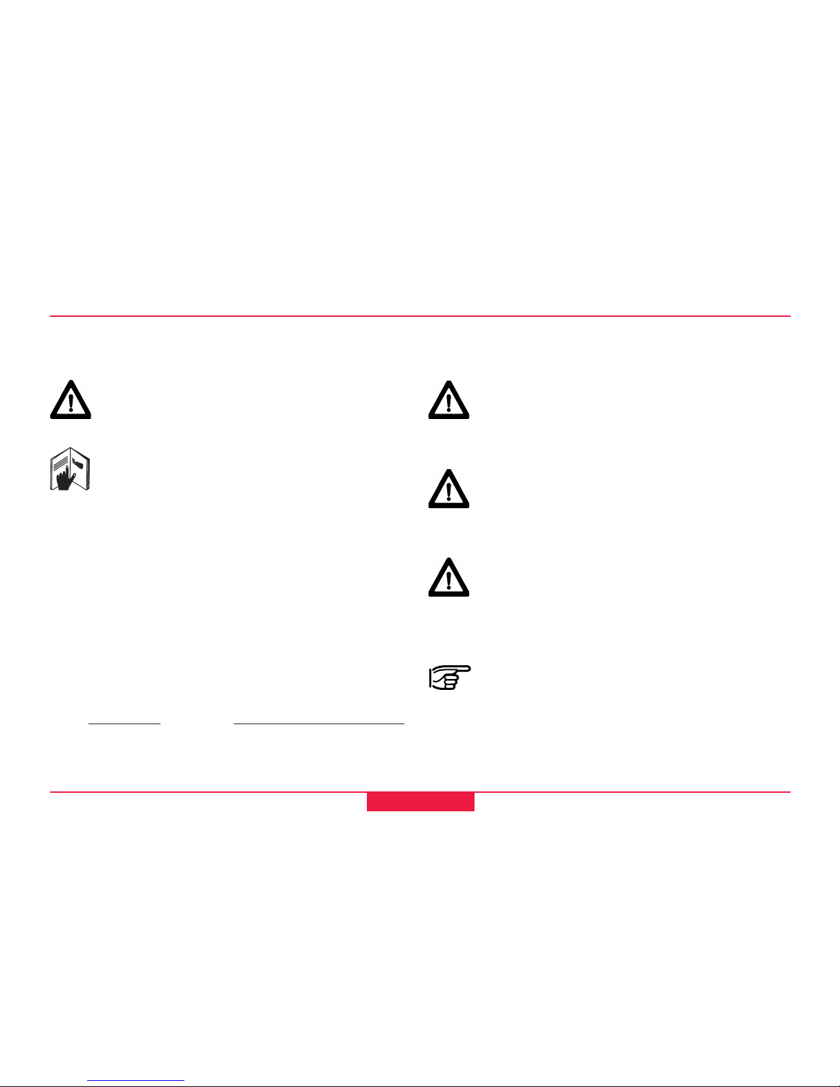
The symbols used in this User Manual have the following
meanings:
DANGER:
Indicates an imminently hazardous situation
which, if not avoided, will result in death or
serious injury.
WARNING:
Indicates a potentially hazardous situation or an
unintended use which, if not avoided, could result
in death or serious injury.
CAUTION:
Indicates a potentially hazardous situation or an
unintended use which, if not avoided, may result
in minor or moderate injury and / or appreciable
material, financial and environmental damage.
Important paragraphs which must be adhered to
in practice as they enable the product to be used
in a technically correct and efficient manner.
Symbols used in this manual
Congratulations on your purchase of a new Leica
Geosystems Theodolite.
This manual contains important safety directions
(refer to section "Safety directions") as well as
instructions for setting up the instrument and
operating it.
Please read this User Manual carefully to achieve
maximum efficiency from your
Instrument.
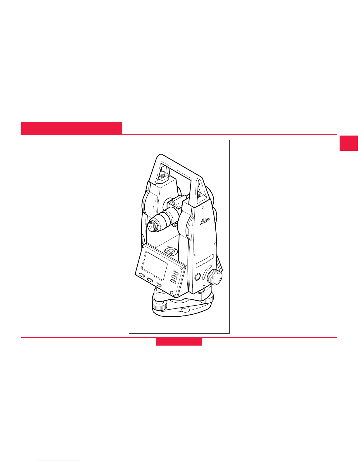
Electronic Theodolite
Product identification

3
T105/T110-1.3.0en
Introduction
Operating the Instrument
Simple measurements
Configuration
Safety Directions
Care and Storage
Accessories
Messages and Warnings
Technical Data
Index
View of chapters
View of chapters
6
10
12
30
39
50
56
57
59
61

4
T105/T110-1.3.0en
Contents
Measuring V-angle .................................................... 23
Extending straight lines .............................................. 24
Staking out vertical lines ............................................ 25
Distance measuring with stadia lines .......................... 26
Instrument errors ....................................................... 27
Line-of-sight error (Hz-collimation) .................................. 27
V-Index (Vertical index error)........................................... 27
Determining the line-of-sight error (c).............................. 28
Determining V-index ....................................................... 29
Configuration ............................................... 30
Setting the beep ........................................................ 31
Setting V-angle .......................................................... 32
Setting display contrast .............................................. 33
Setting the angle units ............................................... 34
V - % .............................................................................. 35
Displayed angle format .............................................. 36
Switching on/off compensator .................................... 37
Switching on/off line-of-sight error correction .............. 38
Introduction ................................................... 6
Special features ........................................................... 6
Important parts ............................................................ 7
Technical terms and abbreviations ............................... 8
Operating the Instrument ........................... 10
Keyboard .................................................................. 10
Buttons ...................................................................... 11
AutoOff ...................................................................... 11
Simple measurements ................................ 12
Unpacking ................................................................. 12
Batteries.................................................................... 13
Inserting / Replacing Battery ...................................... 14
Setting up the tripod................................................... 16
Centring with Laser Plummet, Coarse Level-Up ......... 17
Laser intensity ........................................................... 18
Centring with shiftable tribrach ................................... 18
Hints for positioning ................................................... 19
Accurate levelling-up with electronic level ................... 19
Measuring ................................................................. 20
Setting Hz-direction ........................................................ 21
Setting Hz-circle ............................................................. 21
V-angle display ............................................................... 21
Measuring Hz-angle .................................................. 22
Contents

5
T105/T110-1.3.0en
Safety Directions ......................................... 39
Intended use of instrument ........................................ 39
Permitted uses ............................................................... 39
Adverse uses .................................................................. 39
Limits of use .............................................................. 40
Responsibilities ......................................................... 40
Hazards of use .......................................................... 41
Main hazards of use ....................................................... 41
Laser classification .................................................... 45
Laser plummet ................................................................ 45
Electromagnetic acceptability (EMV) .......................... 48
FCC statement (applicable in U.S.) ............................ 49
Care and Storage......................................... 50
Transport .................................................................. 50
In the field ....................................................................... 50
Inside vehicle.................................................................. 51
Shipping ......................................................................... 51
Storage ..................................................................... 51
Cleaning ......................................................................... 52
Checking and adjusting ............................................. 53
Tripod ............................................................................. 53
Circular level ................................................................... 53
Circular level on the tribrach ........................................... 53
Laser plummet ................................................................ 54
Reticle ............................................................................ 55
Contents, contd.
Contents
Accessories ................................................. 56
Messages and Warnings ............................ 57
Technical Data ............................................. 59
Index ............................................................. 61
6
T105/T110-1.3.0en
Introduction
Introduction
The Leica T105/T110 is a high-quality
electronic theodolite designed for the
construction site.
Its innovative technology makes the
daily surveying jobs easier.
The instrument is ideally suited for
simple construction surveys and
setting out tasks.
The easy operation of the instrument
functions can be quickly learned even
by inexperienced surveyors.
Special features
• Easy and quickly to learn !
• Logically designed keyboard; with
large and clear LCD.
• Attractive design; low weight.
• User setting remain active even
after switching off.
• Continuous drives for horizontal
and vertical angles.
• AutoOFF function to prevent
unneccary power consumption.
• Equipped with laser plummet as
standard.
T100z01
T105
7
T105/T110-1.3.0en
Introduction
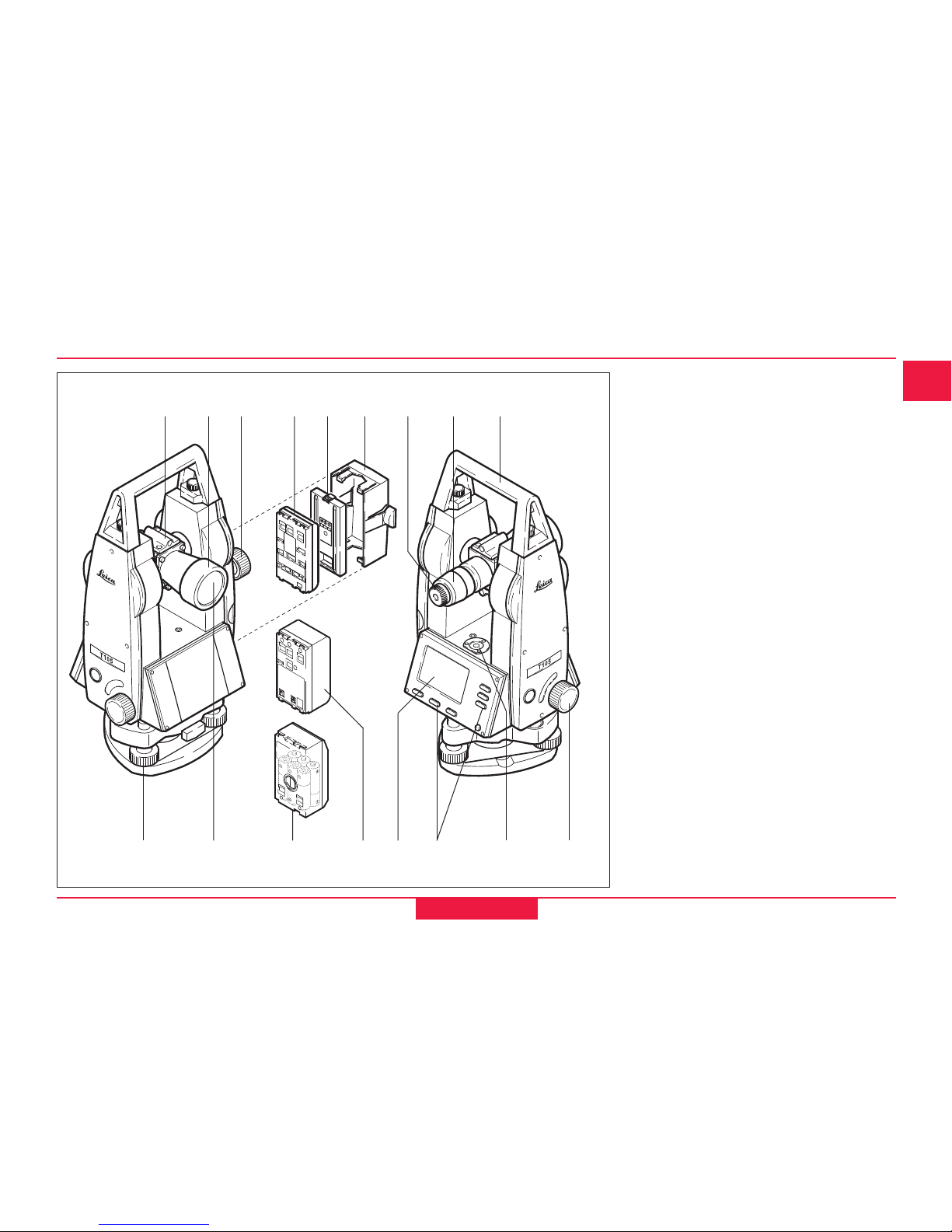
Important parts
1 Optical sight
2 Telescope
3 Vertical drive
4 Battery GEB111 (optional)
5 Battery spacer for GEB111
6 Battery holder for GEB111/
GEB121/GAD39
7 Focussing graticule
8 Focussing telescope image
9 Detachable carrying handle with
mounting screws
10 Foot screw
11 Objective
12 Battery adapter GAD39 for 6
single cells (optional)
13 Battery GEB121 (optional)
14 Display
15 Keyboard
16 Circular level
17 Horizontal drive
1 3
8
9
10 161514
2 4
T100Z02
7
11
5 6
17
1312
8
Introduction
T105/T110-1.3.0en
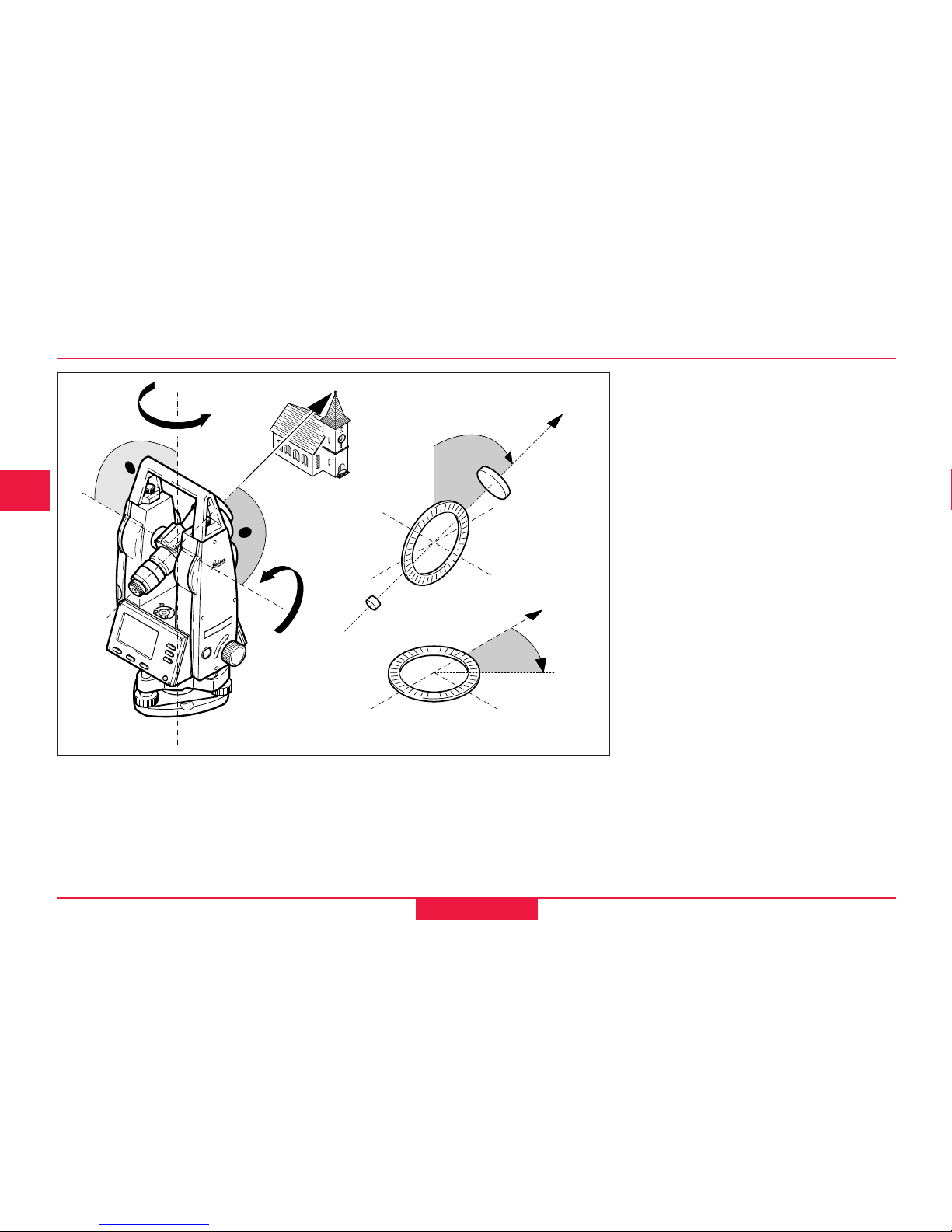
Technical terms and abbreviations
ZA = Line of sight / collimation
axis
Line in space containing all object
points imaged into the graticule
centre at different distance settings
from ¥ to very near.
SA = Standing axis
Vertical rotation axis of the telescope
enables measuring of Hz-angles.
KA = Tilting axis
Horizontal rotation axis of the
telescope enables measuring of Vangles.
V = Vertical angle / zenith angle
VK = Vertical circle
With coded circular division for
reading the V-angle.
Hz = Horizontal angle
HK = Horizontal circle
With coded circular division for
reading the Hz-angle.
Hz0 = Horizontal circle reading 0°
(0 gon)
ZA
ZA
KA
KA
KA
SA
SA
SA
HK
VK
Hz
V
T100Z24
SA
Hz0
9
T105/T110-1.3.0en
Introduction
Technical terms and abbreviations, contd.
c
i
Line-of-sight
error (Hzcollimation)
The line-of-sight
error is the
deviation from
the perpendicular
between tilting
axis and line-ofsight. This is
eleminated by
measuring in two
telescope
positions.
Zenith
Point on the
plumb line above
the observer.
Standing axis
inclination
Angle between
plumb line and
standing axis.
V-index (Vertical
index error)
With horizontal
line-of-sight the
V-curcle reading
should be exactly
90°(100gon). The
deviation from
this values is
termed V-index
(i).
Graticule
Glass plate
within the
telescope with
evaporated
reticle and
distance marks.
Plumb line /
Compensator
Direction of
gravity. The
compensator
defines the
plumb line within
the instrument.
T100Z37
T100Z40
T100Z38
T100Z39
T100Z13
T100Z16
10
Introduction
T105/T110-1.3.0en
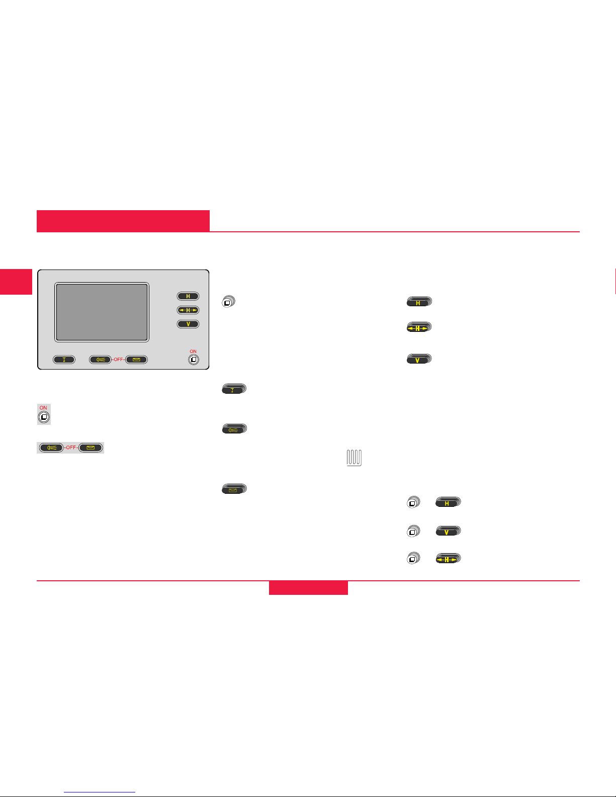
Operating the Instrument
Operating the Instrument
Angle keys
Setting the horizontal angle
and Hz0.
Setting the Hz-angle right or
left.
Switching the vertical angle V
on/off; selecting the display
unit (% or V).
Key combinations
Access to the second key
assignment of the angle keys is
enabled.
Determining line-ofsight error.
Determining vertical
index error.
Activating configuration
menu.
Combi key
Calling quick setting for
compensator, beep and
display contrast.
Function keys
Switching on/off laser
plummet; setting laser
intensity
Switching on/off display
illumination and heating
(active under -5°C; is
displayed)
Switching on/off electronic
level. The laser plummet is
activted simultaneously
+
+
+
Keyboard
ON/OFF keys
Switches instrument ON
Switches instrument OFF
by pressing both keys
simultaneously.
T100Z26

11
T105/T110-1.3.0en
Introduction
Important buttons:
Confirms settings; back into
measuring mode.
Paging through menu (e.g.
within the configuration).
Selection of a setting.
The active selection is always
indicated in the left part of the
display.
Buttons
A button is a symbol in the display
which is always assigned to a
function key directly below it. Buttons
can be found mainly in the
configuration menu.
Find more and detailled
information about buttons in
the relevant sections.
AutoOff
The instrument is equipped with an
automatic switching off function.
Is activated when:
• battery low,
• no action is carried out with the
instrument for 1/3 hour (= no key
pressed; V and Hz angle deviation
£ ±3' / ±600cc).
The function AutoOff cannot
be deactivated.
Operating the Instrument

12
Introduction
T105/T110-1.3.0en
Simple measurements
1 Allen key (2x)
2 Adjusting pins (2x)
3 Removable tribrach GDF101 /
Shiftable tribrach GUS75 (optional)
4 Battery charger and accessories
(optional)
5 Battery GEB111 (optional)
6 GHT196 Spacing Bracket (optio-
nal)
7 GHM007 Instrument Height
Meter (optional)
8 Theodolite
9 User Manual
10 Protective cover / Lens hood
Unpacking
Remove T105/T110 from transport case and check for completeness:
Simple measurements
T100Z31
3
1/2
4
8
9
10
5
7
6
13
T105/T110-1.3.0en
Simple measurements
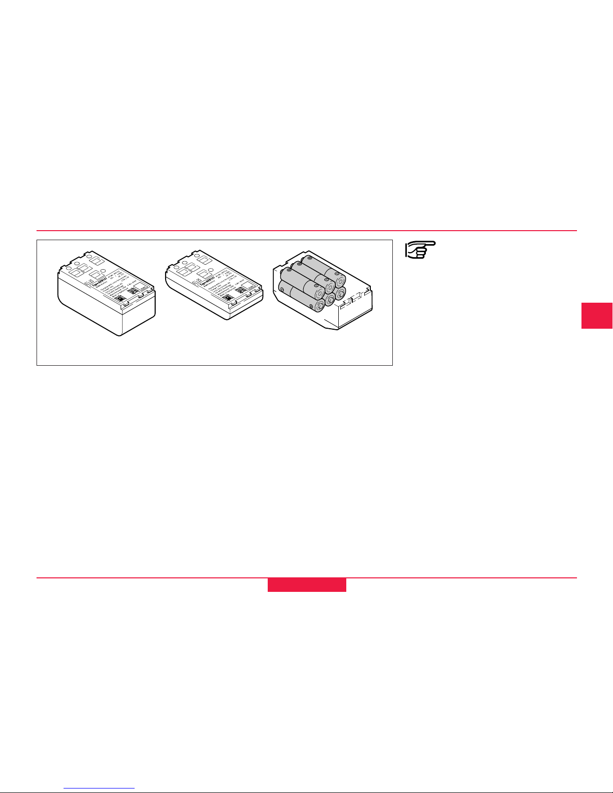
8
12
GEB111GEB121 Individual cells in the
battery adapter GAD39
T100z79
Batteries
Your Leica Geosystems instrument is
operated with rechargable plug-in
batteries. The Basic battery
(GEB111) or the Pro battery
(GEB121) is recommended for T105/
T110 instruments. As an option, six
individual cells can be used with the
appropriate battery adapter GAD39.
Six individual cells (1.5 V each)
produce a voltage of 9 Volts. The
battery indicator in the display is
designed for a voltage of 6 Volts
(GEB111/GEB121). For this reason
the charge state of individual cells is
not indicated correctly. The battery
adapter with individual cells should
therefore be used as a backup. The
advantage of individual cells is the
low self-discharge rate - even over
longer periods of time.
Use the Leica Geosystems
batteries, chargers and
accessories or accessories
recommended by Leica
Geosystems to ensure the
correct functionality of the
instrument.
14
Simple measurements
T105/T110-1.3.0en
8
12
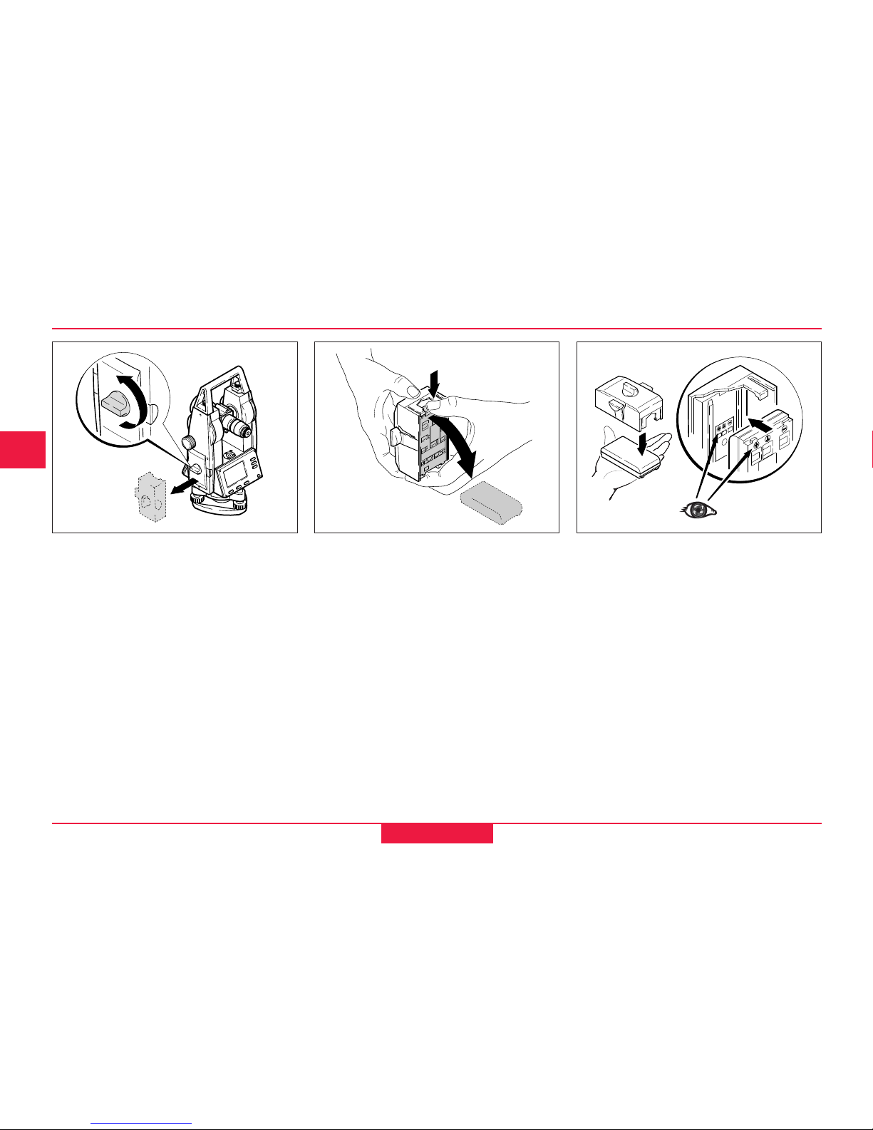
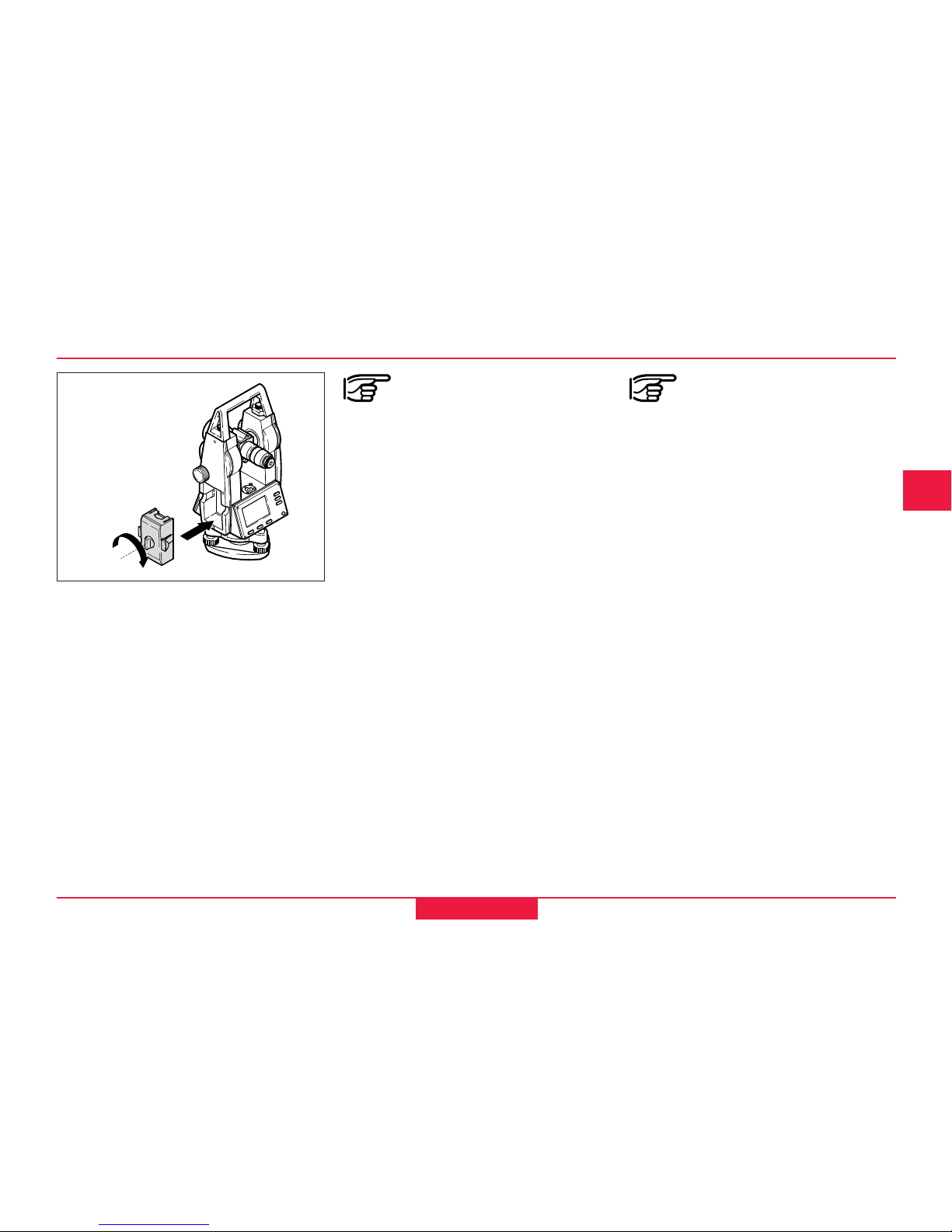
Inserting / Replacing Battery
1. Remove battery holder. 2. Remove battery and replace. 3. Insert battery into battery holder.
T100Z03
T100Z05
T100Z04
15
T105/T110-1.3.0en
Simple measurements
8
12
T100Z06
4. Insert battery holder into
instrument.
Inserting / Replacing Battery, continued
Insert battery correctly (note
pole markings on the inside
of the battery cover). Check and
insert battery holder true to side into
the housing.
• For type of battery see section
"Technical Data".
If the battery GEB121 or the
battery adapter GAD39 for
six individual cells is used, the spacer
for the GEB111 must be removed
from the battery holder prior to
inserting the battery.
16
Simple measurements
T105/T110-1.3.0en
8
12
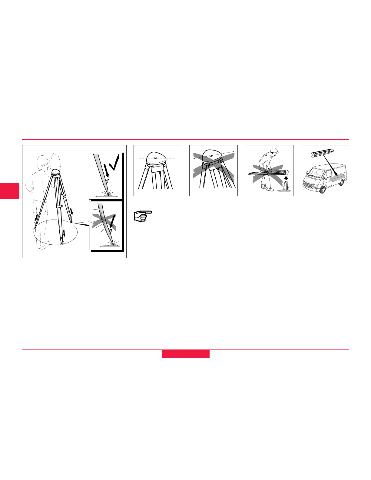
T100Z32
When setting up the tripod
pay attention to a horizontal
position of the tripod plate.
Heavy inclinations of the tripod must
be corrected with the footscrews of
the tribrach.
T100Z33
Setting up the tripod
1. Loosen screws of tripod legs, pull
out to required length and tighten
screws.
2. In order to guarantee a firm
foothold sufficiently press the
tripod legs into the ground.
When pressing the legs into the
ground note that the force must be
applied along the legs.
Careful handling of tripod
• Check all screws and bolts for
correct fit.
• During transport always use the
cover supplied.
Scratches and other damages can
result in poor fit and measuring
inaccuracies.
• Use the tripod only for surveying
jobs.
T100Z57
T100Z19
1.
1.
1.
2.
2.
2.
T100Z58
17
T105/T110-1.3.0en
Simple measurements
8
12
T100Z07
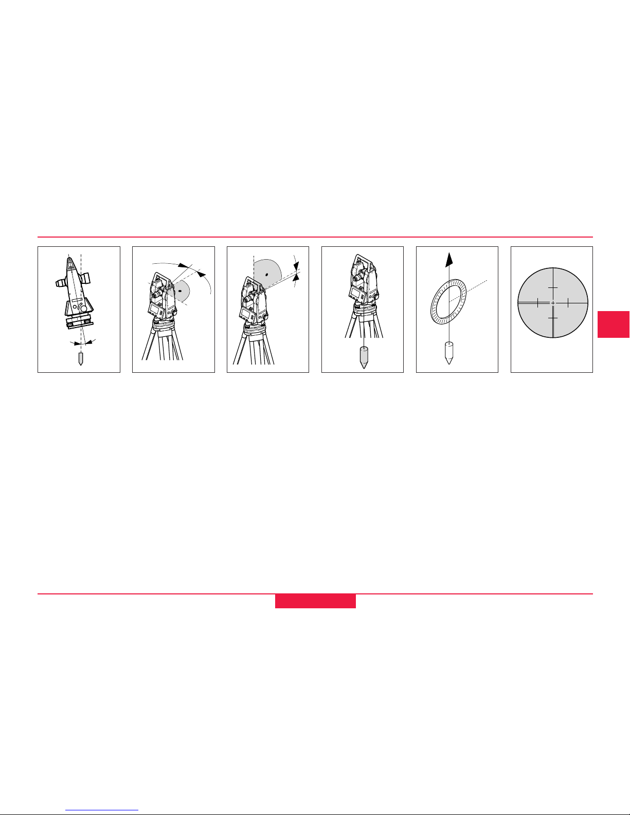
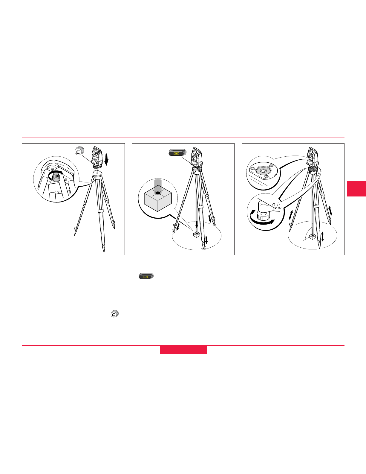
Centring with Laser Plummet, Coarse Level-Up
1. Place the instrument onto the
tripod head.
Tighten central fixing screw of
tripod slightly.
2. Turn footscrews of tribrach into its
centre position.
3. Switch on the instrument with .
4. Switch on laser plummet with
. The electronic level
appears in the display.
5. Position tripod legs so that the
laser beam is aimed to the ground
point.
6. Firmly press in tripod legs.
7. Turn the footscrews of the tribrach
to centre the laser beam exactly
over the ground point.
8. Move the tripod legs to centre the
circular level. The instrument is
now roughly levelled-up.
T100Z08
T100Z09
1.
1.
3.
6.
4.
6.
6.
5.
5.
5.
5.
8.
8.
7.
8.
8.
7.
18
Simple measurements
T105/T110-1.3.0en
8
12
Changing the laser intensity.
Possible adjustments:
Intensity min.
Intensity 25%
Intensity 50%
Intensity 75%
Intensity max.
Switch off laser plummet with .
Laser intensity
External influences may require the
adjustment of the intensity of the
laser plummet.
Adjusting the laser intensity.
If the instrument is equipped with a
shiftable tribrach it can be aligned to
the station point by slight shifting.
1. Loosen screw.
2. Shift instrument.
3. Fix instrument by turning screw.
Centring with shiftable tribrach
T100Z23
19
T105/T110-1.3.0en
Simple measurements
8
12
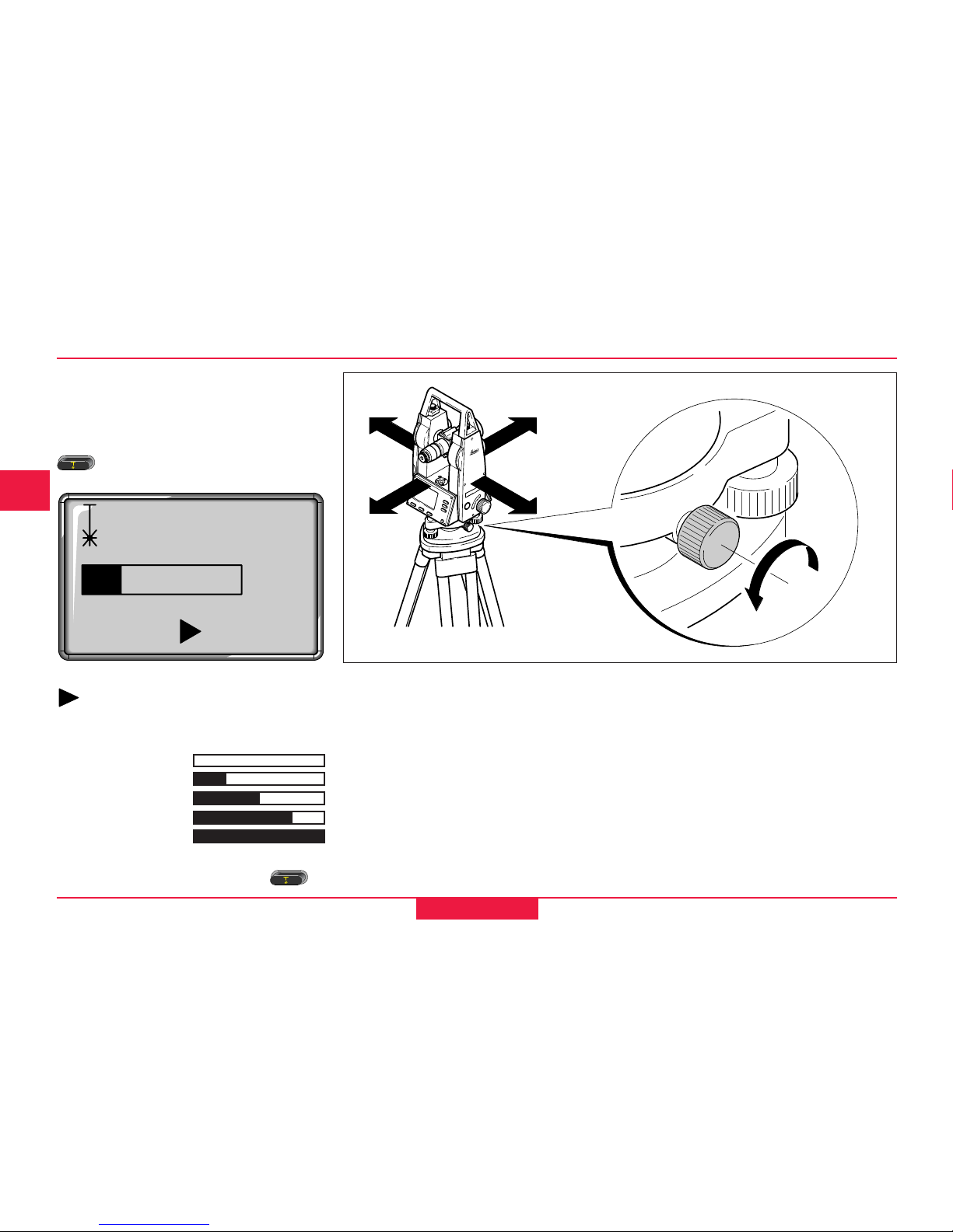
20"
20"
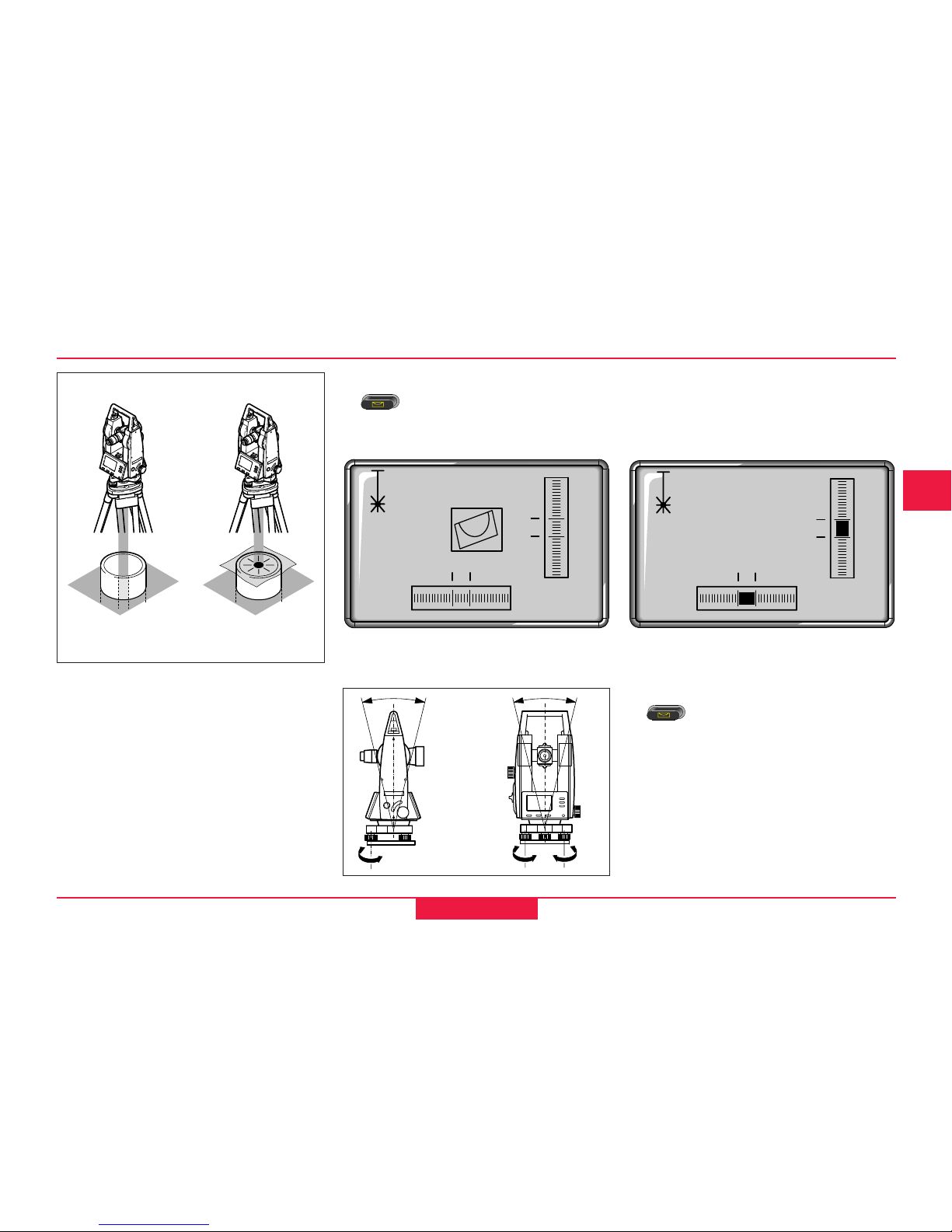
Accurate levelling-up with electronic level
1. Switch on electronic level with
In case of insuffient
levelling-up a inclined level symbol
appears.
3. Check centring with laser plummet
and re-centring if necessary.
4. Switch off electronic level with
.
20"
20"
2. By turning the footscrews centre
the electronic level.
If the electronic level is centered the
instrument is levelled-up.
Positioning over pipes or
depressions
In some cases the laser plummet
cannot be positioned because the
laser spot is not visible. In such
cases, place a transparent plate onto
the pipe. As a result, the pipe
perimeter remains visible and the
laser spot is reflected by the plate.
T100Z35
Hints for positioning
T100Z10
20
Simple measurements
T105/T110-1.3.0en
8
12
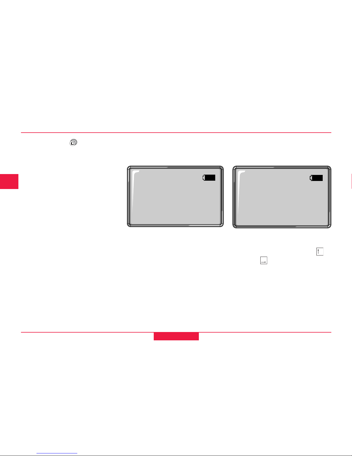
Measuring
After switching on and setting up
correctly, the instrument is
immediately ready for measuring.
Depending on setting the following display appears:
• Hz-angle in the unit selected
• V-angle in the unit selected and
the setting concerning zenith V or
horizon V (see chapter
"Configuration / Setting V-angle")
• battery condition
is indicated.
H: 123°12'50"
H: 123°12'50"
V: 90°00'30"
• Hz-angle in the unit selected (see
chapter "Configuration / Angle
units")
• battery condition
is indicated.
Display 1 Display 2
 Loading...