

LEICA RX1200 User Guide
Version 6.0
English
Leica RX1200
User Manual
Introduction
Introduction
Purchase Congratulations on the purchase of an RX1200.
This manual contains important safety directions as well as instructions for setting
up the product and operating it. Refer to "7 Safety Directions" for further information.
Read carefully through the User Manual before you switch on the product.
2RX1200
Product
identification
The type and serial number of your product are indicated on the type plate.
Enter the type and serial number in your manual and always refer to this information
when you need to contact your agency or Leica Geosystems authorized service
workshop.
Type: _______________
Serial No.: _______________
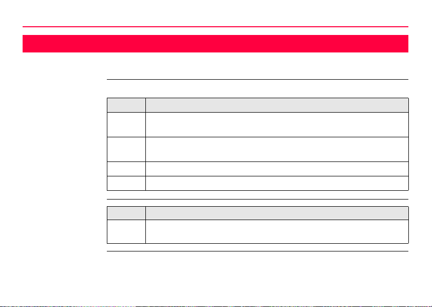
Symbols The symbols used in this manual have the following meanings:
Type Description
Danger Indicates an imminently hazardous situation which, if not
Warning Indicates a potentially hazardous situation or an unintended
Caution Indicates a potentially hazardous situation or an unintended
)
Trademarks • Windows and Windows CE are a registered trademark of Microsoft Corporation
• CompactFlash and CF are trademarks of SanDisk Corporation
• Bluetooth is a registered trademark of Bluetooth SIG, Inc
All other trademarks are the property of their respective owners.
Introduction RX1200 3
avoided, will result in death or serious injury.
use which, if not avoided, could result in death or serious
injury.
use which, if not avoided, may result in minor or moderate
injury and/or appreciable material, financial and environmental
damage.
Important paragraphs which must be adhered to in practice as
they enable the product to be used in a technically correct and
efficient manner.
Introduction
Validity of this
manual
4RX1200
This manual applies to all RX controllers. Differences between the various models
are marked and described.
Available
documentation
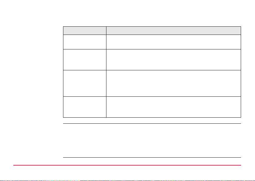
Name Description/Format of RX1200 manuals
User Manual All instructions required in order to operate the product
to a basic level are contained in the User Manual.
Provides an overview of the product together with technical data and safety directions.
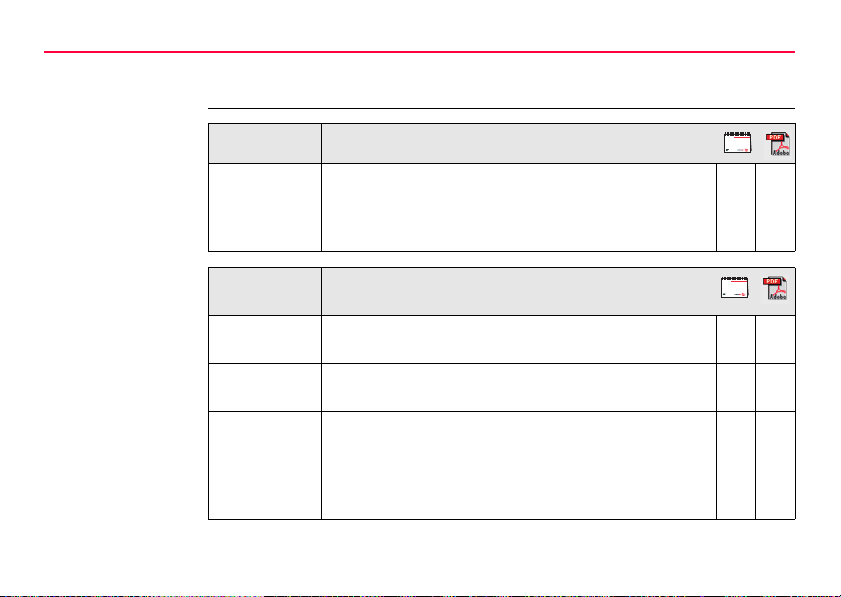
Name Description/Format of
GPS1200/TPS1200+/TPS1200 manuals
System Field
Manual
Applications
Field Manual
Technical
Reference
Manual
Describes the general working of the product in
standard use. Intended as a quick reference field guide.
Describes specific onboard application programs in
standard use. Intended as a quick reference field guide.
Overall comprehensive guide to the product and
program functions. Included are detailed descriptions
of special software/hardware settings and software/hardware functions intended for technical specialists.
99
9
99
9

Refer to the following resources for all System1200 documentation/software:
• the SmartWorx DVD
• http://www.leica-geosystems.com/downloads
Introduction RX1200 5

Table of Contents
Table of Contents
In this manual Chapter Page
1 Description of the System 12
1.1 Terminology 12
1.2 System Concept 15
1.2.1 Software Concept 15
1.2.2 Data Storage and Data Conversion Concept 19
1.2.3 Power Concept 21
1.3 Container Contents 22
1.4 RX Components 24
2 User Interface 26
2.1 Keyboard 26
2.2 Screen 30
2.3 Operating Principles 32
2.4 Icons 33
6RX1200

3 Setting up the Equipment 38
3.1 Equipment Setup 38
3.1.1 Fixing the RX to a Holder and Pole 38
3.1.2 Fixing the RX to a Handstrap 43
3.1.3 Fixing the RX to a GNSS Receiver 44
3.1.4 Setting up for Remote Control (with the RadioHandle) 46
3.1.5 Setting up for Remote Control (with the TCPS27) 47
3.1.6 Setting up SmartPole 49
3.1.7 Setting up a Real-Time Reference 51
3.1.8 Setting up SmartRover 52
3.2 Batteries 54
3.2.1 Operating Principles 54
3.2.2 Battery for all RX1250 models 56
3.2.3 Battery for SmartAntenna 58
3.2.4 Battery for GHT56 60
3.3 Working with the CompactFlash Card 62
3.4 LED Indicators on SmartAntenna 66
3.5 LED Indicators on GHT56 68
3.6 Working with the Clip-On-Housings for Devices on GHT56 70
3.7 Guidelines for Correct Results with GNSS Surveys 81
Table of Contents RX1200 7

Table of Contents
8RX1200
4 Getting Started with SmartWorx 82
4.1 Overview 82
4.2 Turning on the RX, setting the Instrument Mode and Interface 83
4.3 Understanding the Main Menu 87
4.4 Switching Between GPS and TPS 89
4.5 Working with Licence Keys 92
4.6 Connecting to a Digital Cellular Phone 96
4.7 Connecting to the Disto 98
4.8 Connecting to a Personal Computer 101
4.9 Connecting to a Radio (for Remote Control Surveys) 107
4.9.1 Available Radios 107
4.9.2 Working in Remote Mode 108
4.9.3 Working in Transparent Mode 109
4.9.4 Working in Semi-Transparent Mode 110
4.10 Connecting to the SmartAntenna 111

5 Local Mode 114
5.1 Accessing the Main Configuration Menu 114
5.2 Overview of the Main Configuration Menu 115
5.3 Choosing a Sensor 116
5.4 Local Settings 117
5.5 Radio Settings 121
5.5.1 Radio Communication Settings 121
5.5.2 Configuring the Radios 126
5.6 Working with a Sensor 128
6 Care and Transport 130
6.1 Transport 130
6.2 Storage 131
6.3 Cleaning and Drying 132
Table of Contents RX1200 9

Table of Contents
10RX1200
7 Safety Directions 134
7.1 General Introduction 134
7.2 Intended Use 135
7.3 Limits of Use 137
7.4 Responsibilities 138
7.5 End User Licence Agreement EULA 140
7.6 Hazards of Use 143
7.7 Electromagnetic Compatibility EMC 149
7.8 FCC Statement, Applicable in U.S. 152
8 Trouble Shooting 160

9 Technical Data 168
9.1 RX Technical Data 168
9.2 SmartAntenna Technical Data 174
9.2.1 Tracking Characteristics 174
9.2.2 Accuracy 177
9.2.3 Technical Data 178
9.3 GHT56 Technical Data 182
9.4 Conformity to National Regulations 185
9.4.1 RX1210 185
9.4.2 RX1250, GFU23 186
9.4.3 GFU24, Siemens MC75 188
9.4.4 GFU19 (US), GFU25 (CAN), GFU26 (US) CDMA
9.4.5 SmartAntenna with Bluetooth 192
10 International Limited Warranty, Software Licence Agreement 194
Appendix A Directory Structure of the Memory Device 196
Appendix B Cables 198
Index 202
Table of Contents RX1200 11
MultiTech MTMMC-C 190
Description of the System
1 Description of the System
1.1 Terminology
Abbreviations The following abbreviations may be found in this manual:
Term Description
GNSS Global Navigation Satellite System (generic term for satellite based
navigation systems like GPS, GLONASS, SBAS)
LGO LEICA Geo Office (office software consisting of a suite of standard and
extended programs for the viewing, exchange and management of data)
RCS Remote Control Surveying
TPS Total Station Positioning System
12RX1200
RX
general description
Type Description
RX or
RX1200
This is a collective term describing the various models of the multipurpose controller which is used with GPS and TPS instruments.
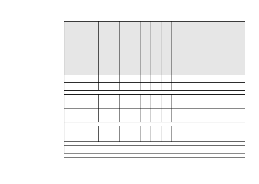
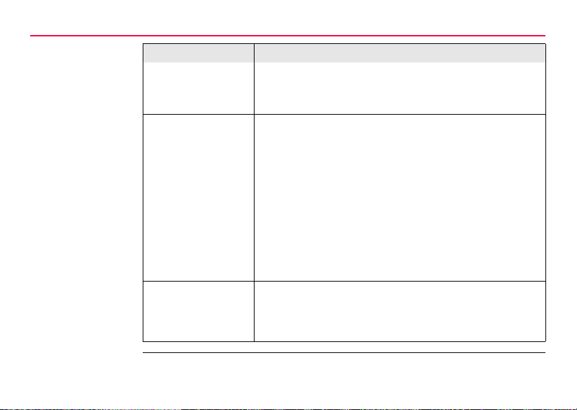
RX
available models
Model
RX1210 9 GPS1200 GX Receiver
RX1210T 99 GPS1200 GX Receiver
RX1250T 99 99999TPS1200+/TPS1200 instru-
RX1250Tc 9 999999TPS1200+/TPS1200 instru-
RX1250X 99 9999GPS1200 SmartRover
RX1250Xc 999999GPS1200 SmartRover
)
Description of the System RX1200 13
Touch screen
Display-monochrome
Display-colour
Internal radio modem
Internal battery
CompactFlash card
Bluetooth
Windows CE
Recommended for ...
ments
ments
Use the supplied stylus on the screens of the touch screen models.
Description of the System
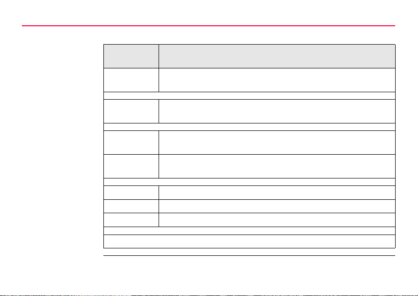
RX
available radios
Radios for remote control (RCS) are found in the following devices:
Radio
Modem
GFU23 Clip-on-Housing with an integrated radio modem and attached
RadioHandle Instrument carry handle with an integrated radio modem and
RX1250T Controller with an integrated radio modem and attached radio
RX1250Tc Controller with an integrated radio modem and attached radio
TCPS27 External radio modem with attached radio antenna.
TCPS27B TCPS27 set to operate as a base radio.
TCPS27R TCPS27 set to operate as a remote radio.
14RX1200
Description
radio antenna.
attached radio antenna.
antenna. This controller has a monochrome display.
antenna. This controller has a colour display.
)
All devices contain the same spread spectrum transceiver radio modem.
1.2 System Concept
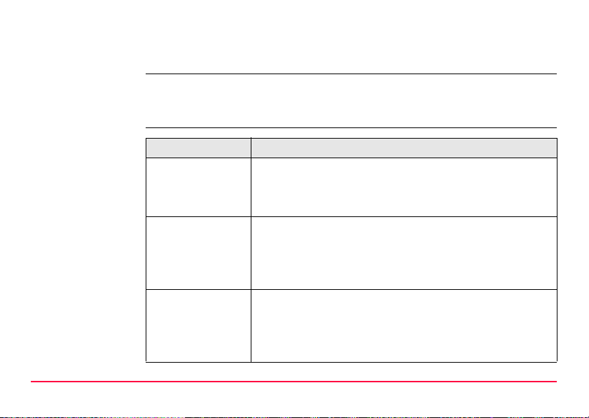
1.2.1 Software Concept
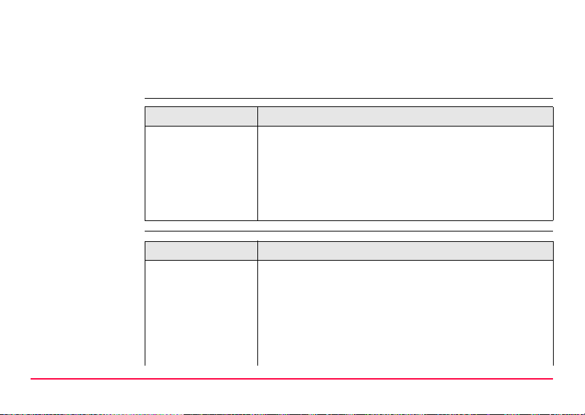
Software for
RX1210/RX1210T
Software for all
RX1250 models
Description of the System RX1200 15
Software type Description
RX firmware
(RX1200.fw)
Software type Description
RX firmware
(RX1250_xx.fw)
These RX models are used as terminals and only one software is required to be installed. All other necessary software is loaded onto the GPS/TPS.
This software includes all the local display, sound and
communication settings. These settings can only be
changed by putting the RX into local mode.
These RX models can be used as data loggers or terminals.
The same amount of software is required to be installed as
for the GPS/TPS. This software includes:
- The local display, sound and communication settings.
- The language specific version of Windows CE.
- The basic functionality of the RX.
Description of the System
Software type Description
Language software
(SYS_LANG.sxx)
Application programs
(RX_program.axx)
16RX1200
- The programs Survey and Wake-Up (for GPS) and Survey
and Setup (for TPS), which cannot be deleted.
- The English language, which cannot be deleted.
Numerous languages are available for the RX. Language
software is also referred to as system language.
The system software enables a maximum of three
languages which can be stored at any one time - the English
language and two other languages. The English language
is the default language and cannot be deleted. One
language is chosen as the active language.
A suite of optional survey-specific application programs are
available for the instrument.
Some of these programs are freely available and can be
loaded and are immediately activated. The other programs
must be purchased and are only activated with a licence
key.
Software type Description
Customised application programs
Custom software specific to user requirements can be
developed using the GeoC++ development kit.
Information on the GeoC++ development environment is
available on request from a Leica Geosystems representative.
Software for the
SmartAntenna
Software upload
Description of the System RX1200 17
Software type Description
SmartAntenna
software
Software for Description
RX1210/RX1210T This firmware can be uploaded to RX via LGO,
This is the software for the ATX1230 GG. It covers the
firmware for the measurement engine.
TPS1200+/TPS1200 or GPS1200.
If TPS1200+ is being used, refer to the TPS1200+ Technical Reference Manual.
If TPS1200 is being used, refer to the TPS1200 Technical
Reference Manual.
Description of the System
Software for Description
All RX1250 models All software is stored in the System RAM of the RX. The
SmartAntenna SmartAntenna must always be connected to an RX1250
18RX1200
If GPS1200 is being used, refer to the GPS1200 Technical
Reference Manual.
If LGO is being used, refer to the online help in LGO.
software can be uploaded onto a CompactFlash card in the
RX.
After uploading, the software must then be transferred from
the CompactFlash card to the RX System RAM. Refer to
GPS1200/TPS1200+/TPS1200 Technical Reference
Manuals for further details.
Microsoft ActiveSync is the synchronization software for
Windows mobile-based pocket PC’s. Microsoft ActiveSync
enables a PC and a Windows mobile-based pocket PC to
communicate.
model when uploading the firmware. Connect SmartAntenna and an RX1250 model via cable. Uploading the
firmware takes some time.

1.2.2 Data Storage and Data Conversion Concept
Description Data is stored within a job in a database on a memory device.
The memory device can be a CompactFlash card or internal memory.
Memory device
)
Description of the System RX1200 19
CompactFlash card: A CompactFlash card slot is standard. A CompactFlash
Unplugging connecting cables or removing the CompactFlash card during the measurement may cause loss of data. Always return to the Main Menu screen before
removing the CompactFlash card and switch off the instrument before removing
cables.
card can be inserted and removed. Available capacity:
256 MB.
)
Whilst other CompactFlash cards may be used,
Leica recommends to only use Leica CompactFlash cards and is not responsible for data loss
or any other error that may occur whilst using a
non-Leica card.

Description of the System
Data conversion Export
Data can be exported from a job in a wide range of ASCII formats. The export format
is defined in Format Manager which is a PC tool in LEICA Geo Office. Refer to the
online help of LGO for information on creating format files.
Data can also be exported from a job in DXF or LandXML format.
Import
Data can be imported from ASCII, DXF, GSI8 or GSI16 format.
Transfer data Data can be transferred in various ways. Refer to "ActiveSync" and LGO online help.
20RX1200
)
CompactFlash cards can directly be used in an OMNI drive as supplied by Leica
Geosystems. Other PC card drives may require an adaptor.
1.2.3 Power Concept
General Use the Leica Geosystems batteries, chargers and accessories or accessories
Power options
Description of the System RX1200 21
recommended by Leica Geosystems to ensure the correct functionality of the instrument.
Model Power supply
RX1210/RX1210T Via cable, or
Via clip-on connector of the GPS receiver, or
Externally via cable
all RX1250 models Internally via GEB211 battery, or
Externally via cable
If an external power supply is connected and one internal
battery is inserted, then the external power is used.
SmartAntenna Internally via GEB211 battery, or
Externally via cable
If an external power supply is connected and one internal
battery is inserted, then the external power is used.
Description of the System
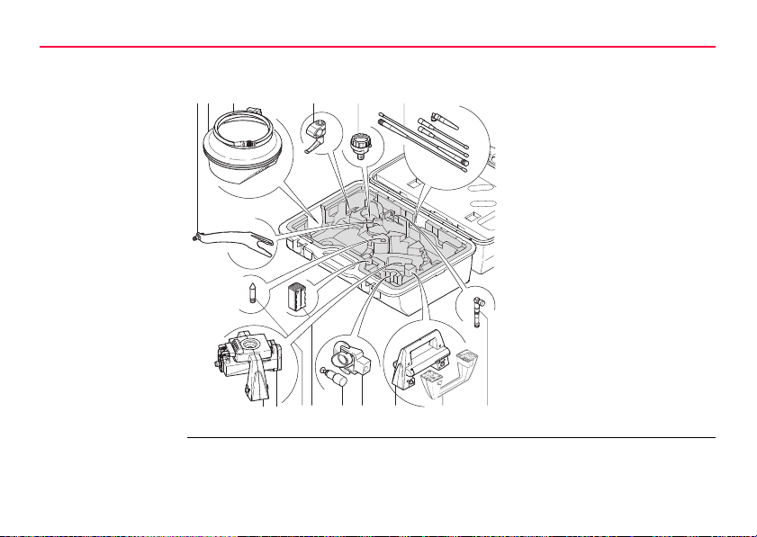
1.3 Container Contents
Container for
System 1200
components
part 1 of 2
aob c d e f
SYS12_001
hg
22RX1200
a) GAD33 Arm 15cm
b) ATX SmartAntenna
c) Cables
d) GHT52 Clamp
e) GAD31 Adapter
f) Radio antennas
g) GAD104 SmartAntenna
Adapter
h) GFU Radio modem
i) Mini Prism spike
j) GEB221 Battery
k) GRZ101 Mini prism and
GAD103 Adapter
l) GMP101 Mini prism
m) RH1200 RadioHandle
n) Instrument carry handle
i
j
nmlk
o) GAT15 Antenna
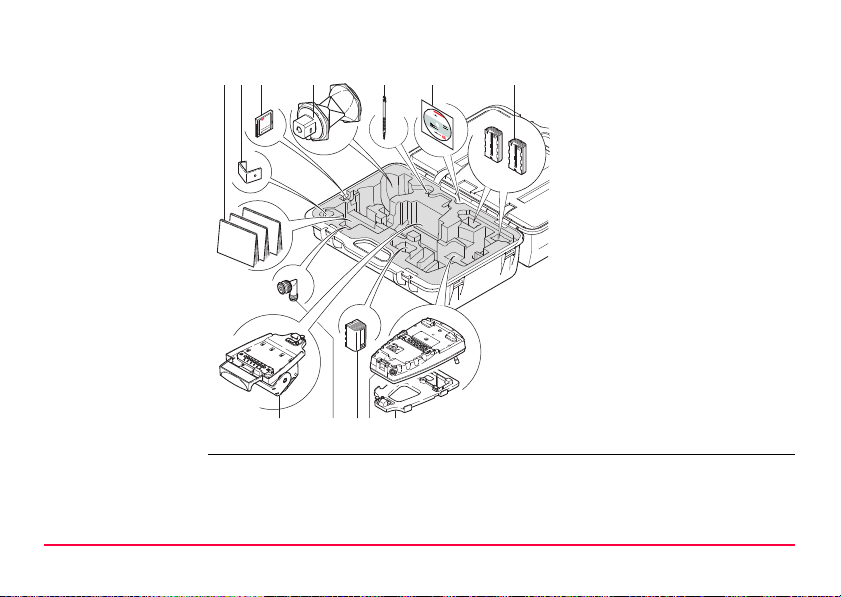
Container for
a b
h
ji k l
c d e fg
SYS12_002
System 1200
components
part 2 of 2
a) Manuals
b) GHT57 Bracket
c) CompactFlash card
d) GRZ4 / GRZ122 Prism
e) Spare stylus
f) Software DVD
g) GEB211 Batteries
h) GHT56 Holder
i) TNC L-adapter
j) GEB221 Battery
k) RX Controller
l) GHT39 Holding plate
Description of the System RX1200 23
Description of the System
RX12_017
a
c
d
e
b
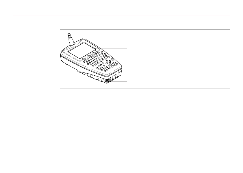
1.4 RX Components
Upperside of RX
24RX1200
a) For RX1250T/RX1250Tc: Radio antenna
b) Screen
c) Keyboard
d) Hand strap bottom clips
e) LEMO port: for RX1250 including USB port
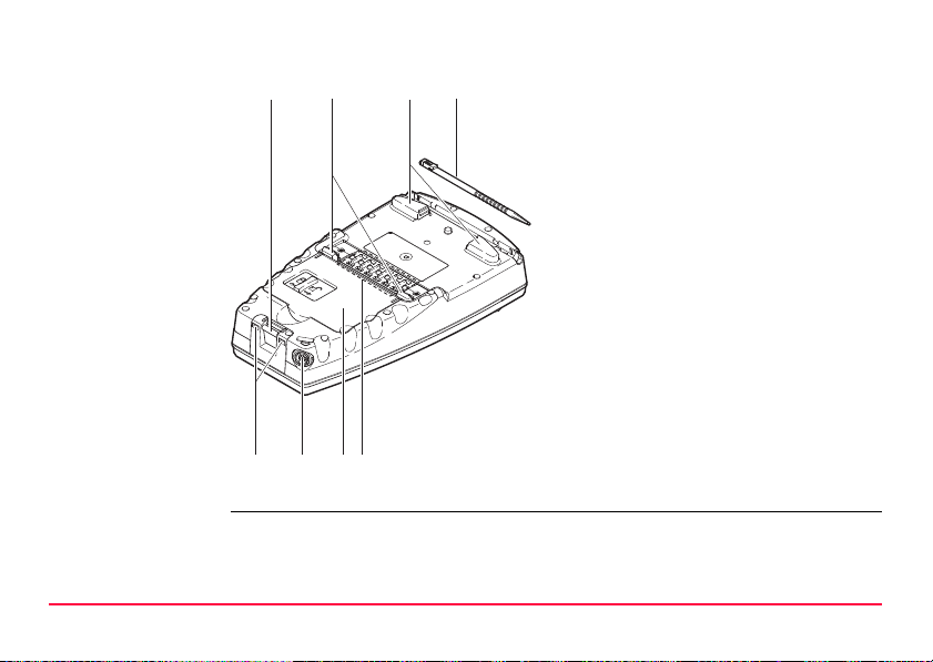
Underside of RX
a
b
c
d
a) Bottom spring clip for pole holder
b) Top clips for pole holder
c) Hand strap top clips
d) Stylus
e) Hand strap bottom clips
f) LEMO port
For RX1250 including USB port
g) Battery compartment
For RX1250 with CompactFlash card
compartment
h) Clip-on-contacts
For RX1250, a Bluetooth port is included
inside to facilitate connectivity to the
e
RX12_002
f
g
h
SmartAntenna, digital cellular phone or
Leica Disto
TM
.
Description of the System RX1200 25
User Interface
F2 F1 F3 F4 F5 F6
F7
A S D F G H J K L
W Q E R
7 8 9
4 5 6
1 2 3
0
.
T Y U I O
P
Z X C V B N M
F8
F9 F10 F11
F12
CE
ESC
USER PROG
ON
RX12_001
a
b
g
f
e
c
d
h
i
SHIFT
SPACE
CAPS
OFF
PgDn
PgUp
ESC
PROG
ON
j
OFF
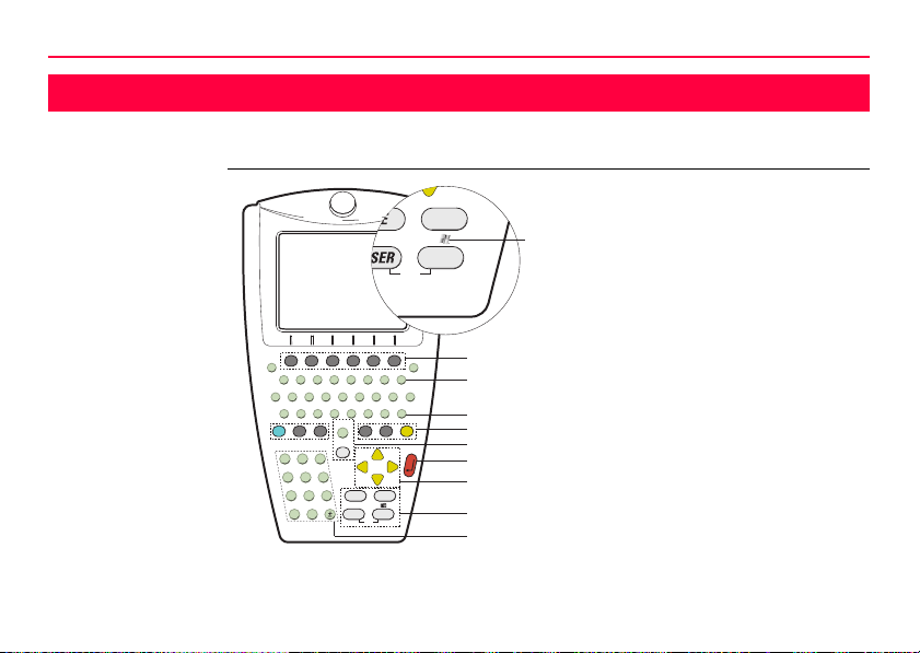
2 User Interface
2.1 Keyboard
Keyboard display
26RX1200
a) Function keys F1-F6
b) Alpha keys
c) CAPS
d) Hot keys F7-F12
e) SPACE, SHIFT
f) ENTER
g) Arrow keys
h) CE, ESC, USER, PROG
i) Numeric keys
j) For all RX1250 models:
Windows key symbol. It is the Microsoft flag logo located between PROG
and ESC.
)
For the purpose of the illustration, a RX1250 model has been selected which is
representative for all models. Differences to other RX models are outlined.
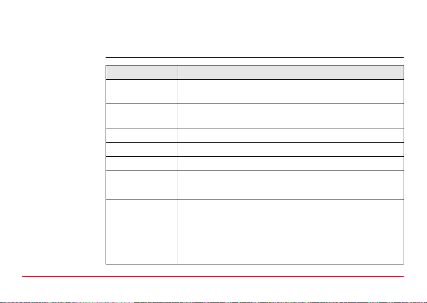
Keys
User Interface RX1200 27
Key Function
Function keys
F1-F6
Hot keys
F7-F12
Alpha keys To type letters.
Numeric keys To type numbers.
CAPS Switches between upper case and lower case letters.
CE Clears all entry at the beginning of user input.
ESC Leaves the current screen without storing any changes.
Correspond to six softkeys that appear on the bottom of the
screen when the screen is activated.
User definable keys to execute chosen commands or access
chosen screens.
Clears the last character during user input.
In SmartWorx mode and in the Main Menu:
Turns RX off when held for 2 s.
In Terminal mode:
Turns RX off when held for 2 s
User Interface
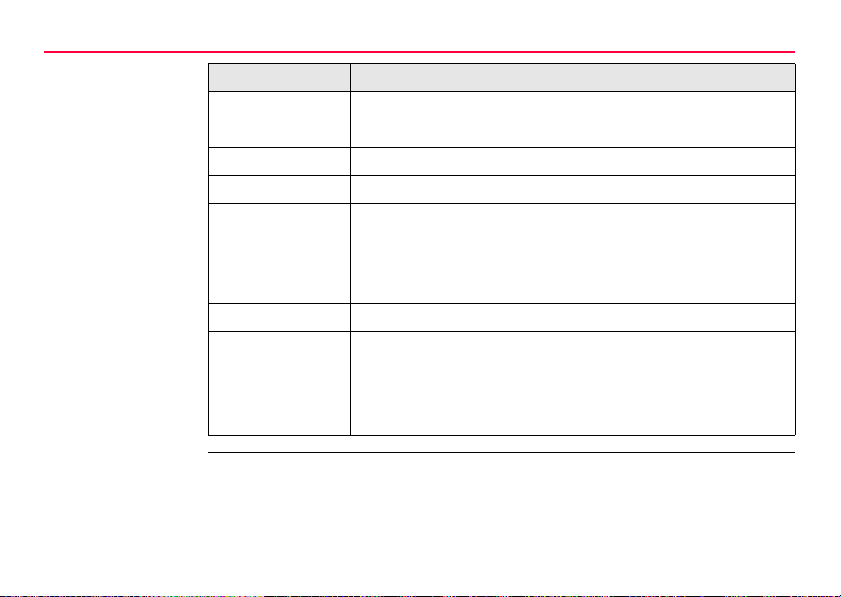
28RX1200
Key Function
PROG (ON) If RX is already off: Turns RX on.
If RX is already on: Accesses the Programs menu.
SHIFT Switches between the first and second level of function keys.
SPACE Enters a blank.
USER In SmartWorx mode:
Calls the user defined menu.
In Terminal mode:
Hold down for 2 s to open the Main Configuration Menu.
Arrow keys Move the focus on the screen.
ENTER Selects the highlighted line and leads to the next logical
menu / dialog.
Starts the edit mode for edit fields.
Opens a choicelist.
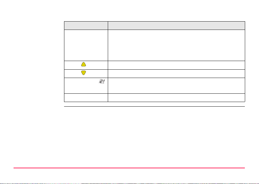
Key combinations
User Interface RX1200 29
Key Function
PROG plus USER In SmartWorx mode and in the Main Menu:
Turns RX off when pressed simultaneously.
In Terminal mode:
Turns RX off when pressed simultaneously.
SHIFT Pages up.
SHIFT Pages down.
SHIFT PROG ( ) For all RX1250 models:
Displays the Windows desktop, task bar and start menu.
USER STAT (F3) Opens the Status Menu.
User Interface
a
g
i
j
h
b
c
d
e
k
f
S_RX12_001
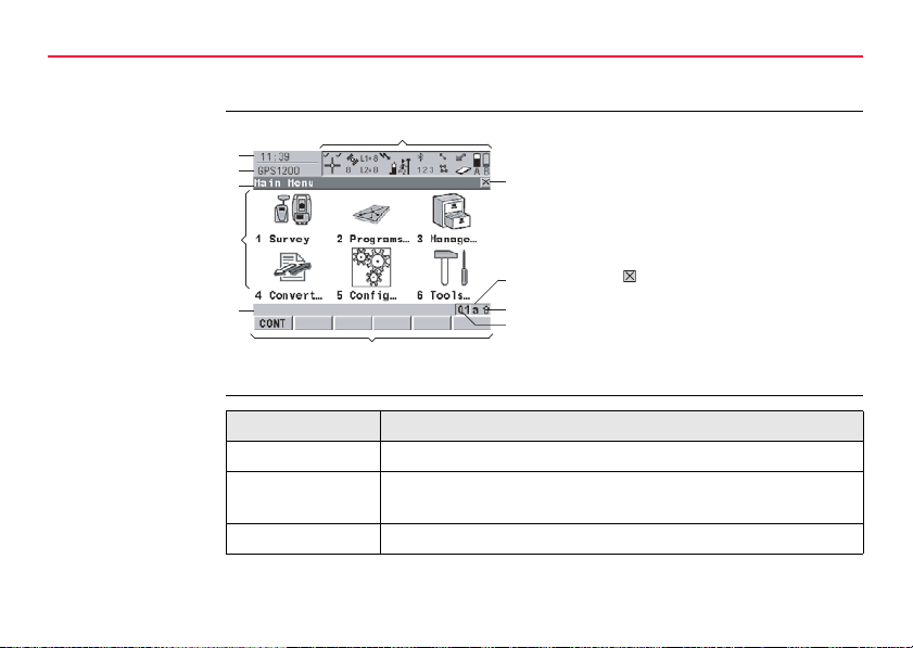
2.2 Screen
30RX1200
Screen
Elements
a) Time
b) Caption
c) Title
d) Screen area
e) Message line
f) Icons
g) ESC
h) CAPS
i) SHIFT icon
j) Quick coding icon
k) Softkeys
Type Description
Time The current local time is shown.
Caption Shows location either in Main Menu, under PROG key or
USER key.
Title Name of the screen is shown.
 Loading...