

Leica MX535 User Manual

MX535 UAIS Ship Borne Class A
Transponder Unit
Technical & Installation
Manual
WARNING:
THIS EQUIPMENT COMPLIES WITH PART 80 OF THE FCC RULES. ANY
CHANGES OR MODIFICATIONS NOT EXPRESSLY APPROVED BY THE
MANUFACTURER COULD VOID THE USER’S AUTHORITY TO OPERATE THE
EQUIPMENT.
IMPORTANT NOTICE
THE MX535 SYSTEM IS AN AID TO NAVIGATION. UNDER NO CIRCUMSTANCES SHOULD IT BE USED IN LIEU OF
AUTHORIZED GOVERNMENT CHARTS. ITS ACCURACY CAN BE AFFECTED BY MANY FACTORS SUCH AS EQUIPMENT
DEFECTS, ENVIRONMENTAL CONDITIONS, OR IMPROPER OPERATION. THE USER IS RESPONSIBLE FOR SAFE
NAVIGATION OF THE VESSEL. THIS INCLUDES CONSULTING AUTHORIZED GOVERNMENT CHARTS AND
EXERCISING COMMON PRUDENCE AND NAVIGATIONAL JUDGEMENT AT ALL TIMES.

Part No. 3508 102 70870
Rev. D
MX-Marine
January, 2005
By: TCD
This document is the property of MX-Marine.
It must not be reproduced or otherwise made available to any third party
without our permission in writing. Alterations due to technical progress are reserved.
MX Marine (USA)
23868 Hawthorne Blvd., Suite 201
Torrance, CA 90505
USA
+1 310 791 8213 (Telephone)
+1 310 791 6108 (Fax)
MX Marine (UK)
Ocean Quay
Southampton SO14 5QY
United Kingdom
www.mx-marine.com
+44(2380) 33 99 22 (Telephone)
+44(2380) 33 03 45 (Fax)
www.mx-marine.com

How To Contact Us?
Contact your local MX-Marine, Leica dealer for:
• Installation, Service, & Technical Support
• Sales of Accessories
• Hardware and Software Upgrades
Unlike many other consumer electronics industries which only sell consumer electronic devices, your marine dealer
is often your best advisor for installation and service of your new AIS unit. MX-Marine, Leica strongly encourages
you to utilize the knowledge and experience of your sales and service dealer.
Should you need to contact us directly for new sales, upgrades, repair service, or technical support, we can be
reached at the following:
International:
MX-Marine (USA)
23868 Hawthorne Blvd., Suite 201
Torrance, California 90505
USA
+1 310 791 8213 (Telephone)
+1 310 791 6108 (Fax)
In Europe:
MX Marine (UK)
Ocean Quay
Southampton SO14 5QY
United Kingdom
+44(2380) 33 99 22 (Telephone)
+44(2380) 33 03 45 (Fax)
Email: sales@mx-marine.com
support@mx-marine.com
www.mx-marine.com

Table of Contents
1 General .............................................................................................................................................1
1.1 Software Releases ........................................................................................................................1
1.2 General Recommendations for Installation, Maintenance and Repair Work .........................1
1.3 Safety Warnings ............................................................................................................................1
2 Overview ..........................................................................................................................................3
2.1 Supplied Equipment ......................................................................................................................3
2.2 Compatibility with Other Systems ..............................................................................................3
2.3 MX535 Transponder with MX420 CDU ........................................................................................4
2.4 MX535 Transponder Overview ....................................................................................................5
3 Installation ......................................................................................................................................6
3.1 General Requirements .................................................................................................................6
3.2 Installation Overview
3.2.1 Survey .............................................................................................................................................6
3.2.2 Step-by-step Installation Procedure.......................................................................................... .....6
3.2.3 MX535 Connection Diagram ...........................................................................................................7
3.3 Components and Interfaces ........................................................................................................7
3.3.1 General Interface Description .........................................................................................................8
3.3.2 Interface NMEA Description ...........................................................................................................9
3.3.2.1 Sensor – Interface CH1, CH2, CH3 ................................................................................................9
3.3.2.2 ECDIS – Presentation Interface CH4 .............................................................................................9
3.3.2.3 PILOT Port CH5 ............................................................................................................................10
3.3.2.4 LONG RANGE CH8 ......................................................................................................................10
3.3.2.5 DGPS – DGNSS CH9 ...................................................................................................................11
3.3.2.6 ALARM CIRCUIT .........................................................................................................................11
3.4 Sensor Interface Definitions .......................................................................................................11
3.4.1 Sensor Notes .................................................................................................................................12
3.4.2 Sensor Hardware Installation.........................................................................................................13
3.4.3 Priority Handling of Sensor Sentence ...........................................................................................14
3.4.4 Pin-Description AIS Cable/Socket 50-Pins ...................................................................................19
3.5 Installation of VHF/GPS Antennas .............................................................................................21
3.5.1 VHF Antenna Installation ..............................................................................................................21
3.5.2 GNSS Antenna Installation ...........................................................................................................22
3.6 Specific Recommendations........................................................................................................ 23
3.6.1 Recommendations Concerning AIS Systems ...............................................................................23
3.6.2 Recommendations Concerning Installation of Transponder Unit .................................................23
3.6.3 Recommendations Concerning Installation of VHF Antenna .......................................................23
3.6.4 Recommendations Concerning Installation of GPS Antenna .......................................................23
3.6.5 Recommendations Concerning Redundancy ................................................................................24
3.6.6 Emergency Power Source ............................................................................................................24

4 Technical Data ............................................................................................................................25
4.1 Technical Information ................................................................................................................25
5 Setting-to-Work/Configuration .............................................................................................27
5.1 Setting-to-Work ...........................................................................................................................27
5.2 Software Versions ......................................................................................................................27
5.3 Configuration ..............................................................................................................................27
5.3.1 Configuration with MX420/MKD CDU ...........................................................................................27
5.4 Testing .........................................................................................................................................27
6 Repair/Maintenance ..................................................................................................................28
6.1 Trouble Shooting ........................................................................................................................28
6.1.1 Hints ..............................................................................................................................................28
7 Fault Code List ............................................................................................................................31
8 Cabling Documents ..................................................................................................................33
9 PRODUCT WARRANTY ...........................................................................................................35
www.mx-marine.com

List of Abbreviations
This list also contains abbreviations which are not used in this manual but in additional documentation.
A
AIS
B
BIIT Built-In Integrity Test
C
COG Course Over Ground
CDU Control and Display Unit (MX420/MKD)
D
DCU Display and Control Unit (MX420/MKD)
DSC Digital Selective Call
E
ECDIS Electronic Chart Display and Information System
H
HDG Heading
L
LR Long Range
M
MAC Medium Access Control
MKD Minimum Keyboard and Display
MMSI Maritime Mobile Service Identity
P
PDP Primary Display Port (Presentation Interface)
PP Pilot Port (Auxiliary Display Port)
S
SOG Speed Over Ground
U
UAIS Universal shipborne AIS
V
VDL VHF Data Link
VDM Serial output message containing VDL information (IEC 61162-1)
VDO Serial output message containing VDL information (IEC 61162-1) (from own ship)
Universal shipborne Automatic Identification System


MX535 AIS Transponder Unit
Technical & Installation Manual
____________________________________________________________________________________________
1 General
This Technical & Installation Manual is the installation manual for the MX535 AIS Transponder. It also contains
information about the antennas (GPS and VHF) and cabling used by the MX535.
Related Documents
MX420 Operator’s Manual (P/N 3508 102 70040)
1.1 Software Releases
MX535
This manual is valid for all software versions of the MX535. See also Section 5.2.
MX420
The CDU must have the program version V2.0(841) or later to work properly with the MX535 (NAUTICAST) AIS
transponder.
1.2 General Recommendations for Installation, Maintenance and Repair Work
MX-Marine Company gives advice and recommendations for the arrangement of MX-Marine equipment and the
installation sites. A prerequisite is that the necessary drawings of the ship should be made available in good time.
The advice and recommendations contained in this manual are given on the basis of our up-to-date practical
experience and to the best of our knowledge. However, they are given without any commitment. As far as is
permissible, any liability on the part of MX-Marine for resulting damage is expressly ruled out, regardless of whether
the damage is of a direct or indirect nature.
Unusual shipbuilding shapes, additions or superstructures as well as environmental influences can impair the
functioning of the equipment. We are, of course, willing to help the customer with optimising solutions subject to
suitable commercial arrangements.
The customer is responsible for ensuring that the MX-Marine equipment is installed properly according to our
instructions and in compliance with the regulations issued by the relevant classification society and national
authorities.
1.3 Safety Warnings
WARNING
This unit contains electrostatic sensitive devices.
Observe precautions for handling.
The discharge of electrostatic energy into a semiconductor can destroy the semiconductor or change its properties.
Before a unit’s housing is opened to remove or touch a board, the service equipment, Order No. 586-5011, must be
used.
www.MX Marine.com
1
MX535 UAIS Transponder Unit
Technical & Installation Manual
_______________________________________________________________________________________
1. The mat must be positioned at the workplace.
2. The potential equalization cable must be connected to the snap fastener and the clamp to a suitable
protective earth contact. The cable contains a 1 M
Ω resistor, which must not be removed.
3. The wristband must be put on. When the spiral cable is connected to the snap fastener, the discharge
line is established.
4. Thoroughly grounded soldering, measurement and test tools must be used. If these tools are supplied
with power from the 110 or 230 VAC mains, a fault current plug must protect this supply.
Boards and units that contain ESD-endangered semiconductors are marked with the symbol shown above.
All assisting persons who might come into contact with the endangered boards must also use the ESD equipment.
DANGER
It is not permissible to connect the ship’s mains to the system before
setting-to-work by a qualified technician. The mains must be switched off
(e.g. by means of a common isolating switch or a circuit breaker) in the
ship’s supply or the mains cable must be disconnected until setting-to-work
takes place.
If a synchro is connected via an appropriate interface, dangerous voltages
might be present, even although all supplies to the system are switched off.
Capacitors and tubes can store dangerous voltages for several hours, even
when they have been disconnected from the supply voltage.
WARNING
Pay attention to the regulations for the prevention of accidents.
DANGER
Even when the system is switched off, there might be a dangerous voltage
present on exposed contacts. Therefore, before a unit is opened, it must be
ensured that the electrical supply to all units is, and remains, disconnected
from the ship’s mains.
2
www.mx-marine.com

MX535 AIS Transponder Unit
Technical & Installation Manual
____________________________________________________________________________________________
2 Overview
The MX535 is an AIS Transponder Unit, which receives data from other vessels by means of a VHF radio and
sends these data to the MX420 Control and Display Unit (CDU) or the ECDIS.
In the opposite direction, the AIS receives data from the external GPS system and the ship’s sensors and transmit
these data by means of the VHF radio.
Access to these data and access to the VHF radio for a pilot is prepared by means of an additional pilot port.
The AIS has a Long-Range (LR) Port to connect a long-distance communication system, for instance a satellite
communication system. In this way, the AIS can be called to send the ship’s data. These data are sent back via the
long-range port to the questioner.
2.1 Supplied Equipment
The following items are supplied with the MX535 Kit:
Description
MX535 AIS system 9525 200 80800
comprising:
MX535 Transponder 3508 102 70800
Mounting Kit 3508 102 70820
JB-50 Junction Box (optional) 3508 102 70830
AIS Cable 3508 102 70840
GPS/VHF Cable 3508 102 70850
MX535 N(m) / RG214(crimp) 3508 102 70860
MX535 Technical & Installation
Manual 3508 102 70870
Part Number
2.2 Compatibility with Other Systems
The MX535 AIS transponder can be used with the following systems:
MX420/AIS Control and Display Unit (CDU) Version V2.0(841) or later, or MX420 MKD with Program
Version V2.0(841) or later
IMO compliant ECDIS systems (only listening). It is not allowed to transmit data (e.g. VSD, SSD) into
the MX535 via an ECDIS.
It is also possible to use the MX535 within systems from other manufacturers, which support the IEC-defined
interfaces.
www.MX Marine.com
3
MX535 UAIS Transponder Unit
Technical & Installation Manual
____________________________________________________________________________________________
2.3 UAIS MX535 with MX420/AIS or MKD CDU
EXT.
Non-MX535
GPS
ECDIS/ARPA
Listener
MX-MARINE
SMART DGPS
ANTENNA
(NOT USED FOR MKD).
MX420/AIS
OR
MX420/MKD
MX420/MX535 communication
Figure 2.1 - MX535 AIS Transponder with MX420/AIS or MKD CDU
Ch2 (GLL,DTM,VTG)
JB-50
Junction Box
(optional)
3
CH 4
CH 1
CH
GYRO
ROT
RANGE
CH 8
CH 5
LONG
GPS
ANT.
MX535
TRANSPONDER
CH 9
RTCM
SC 104
unit
VHF
ANT.
The Display and Control Unit MX420/AIS is used to configure and operate the MX535 transponder unit. In
this case, the MX420/AIS or MKD can just be a display. For further information refer to the Operator and
Installation Manual of the MX420 Control and Display Unit (CDU).
www.mx-marine.com
4
MX535 UAIS Transponder Unit
Technical & Installation Manual
____________________________________________________________________________________________
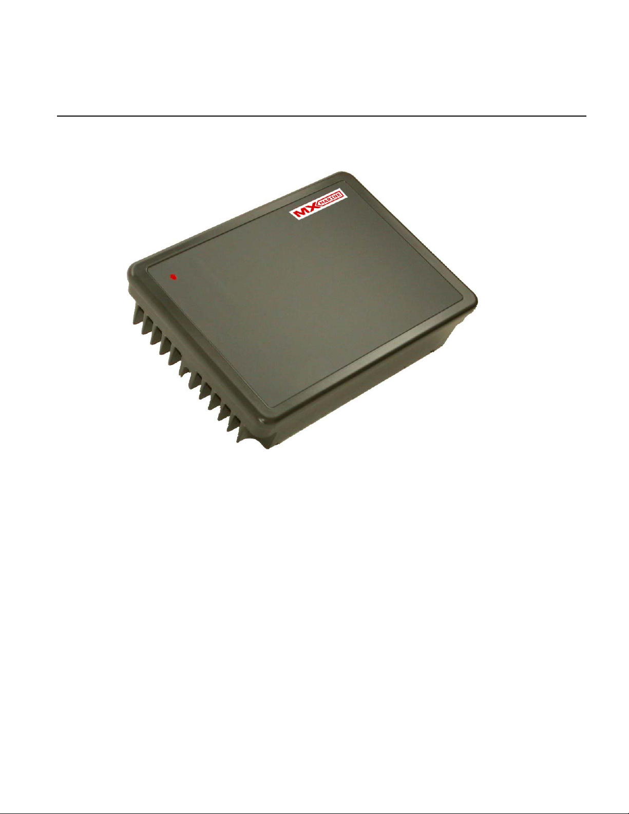
2.4 MX535 Transponder Overview
Figure 2.2 – MX535 UAIS Transponder
The aluminum housing shown in Fig. 2.2 contains a single Transponder Unit, which consists of the:
Controller
Interfaces
VHF transmitter
VHF receivers
GPS receiver.
The housing has two cable connectors (GPS/VHF Interface Cable and AIS Cable) for the connection of:
GPS antenna
VHF antenna
AIS
www.mx-marine.com
5

MX535 UAIS Transponder Unit
Technical & Installation Manual
____________________________________________________________________________________________
3 Installation .
3.1 General Requirements
Please note that international conventions, regulations, instructions and guidelines have to be adhered to when
installing the MX535 AIS transponder.
The following points must be observed before installation can commence:
• Trained service personnel must undertake the installation.
• The MX535 Transponder must be fitted in a suitable place on the bridge.
• The VHF and GPS Antennas must be installed in a suitable position, where excellent reception conditions
apply (refer to Section 3.5, Installation of VHF and GPS antennas – page 21)
• All available interfaces must be installed.
• The vessels power supply must suffice, and the GMDSS power supply has to be used.
• Installation of the pilot plug in conning position (close to the pilot working place).
3.2 Installation Overview
3.2.1 Survey
AIS is considered part of the ship’s radio station and is surveyed together with radio installation. Surveys on
SOLAS Convention ships should be carried out in accordance with the rules laid down in IMO Res. A 746(18)
"Survey Guidelines under the harmonised system of survey and certification" (R) 8, and "Protocol of 1988
relating to the International Convention for the Safety of Life at Sea, 1974."
The MX535 system consists of the MX535 Transponder Unit, MX420 CDU, VHF Antenna, Backup GPS
Antenna, MX521(MX525) Smart Antenna, and associated cable.
3.2.2 Step-by-Step Installation Procedure
• Use the VHF adapter cable (P/N 3508 102 70850) together with the VHF plug and TNC plug to connect the
VHF and GPS antenna cables as well as the antennas.
• The sensors, ECDIS, PC, pilot case, long range devices and auxiliary displays can be connected to the
MX535 transponder cabinet by the AIS cable or JB-50 Junction Box (optional). The device is driven by a
24V DC 7A supply, which is connected to the power terminal at the JB-50 Junction Box (optional). The AIS
should be connected to an emergency power source. A battery capacity calculation together with GMDSSequipment is needed! After performing these steps, the MX535 transponder automatically starts operation.
• The MX535 transponder has a ground terminal, which has to be connected to ship ground.
6
www.mx-marine.com
MX535 UAIS Transponder Unit
Technical & Installation Manual
___________________________________________________________________________________________________________________
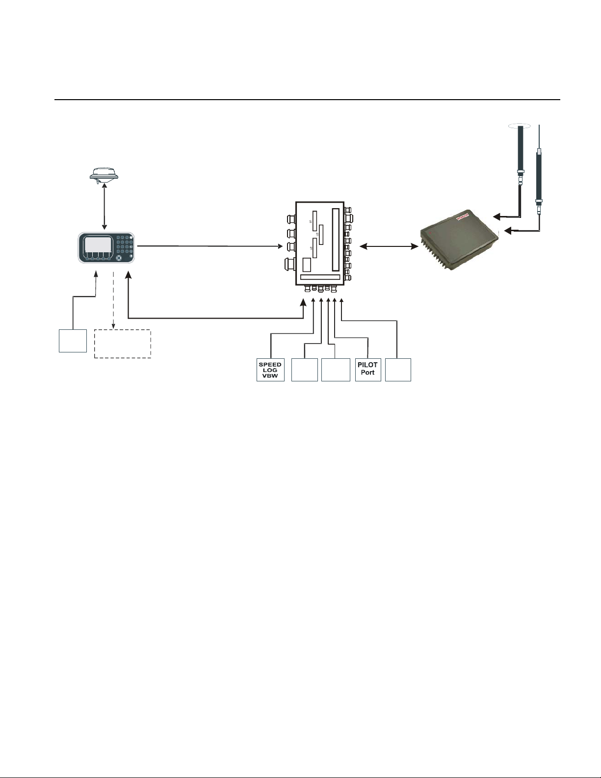
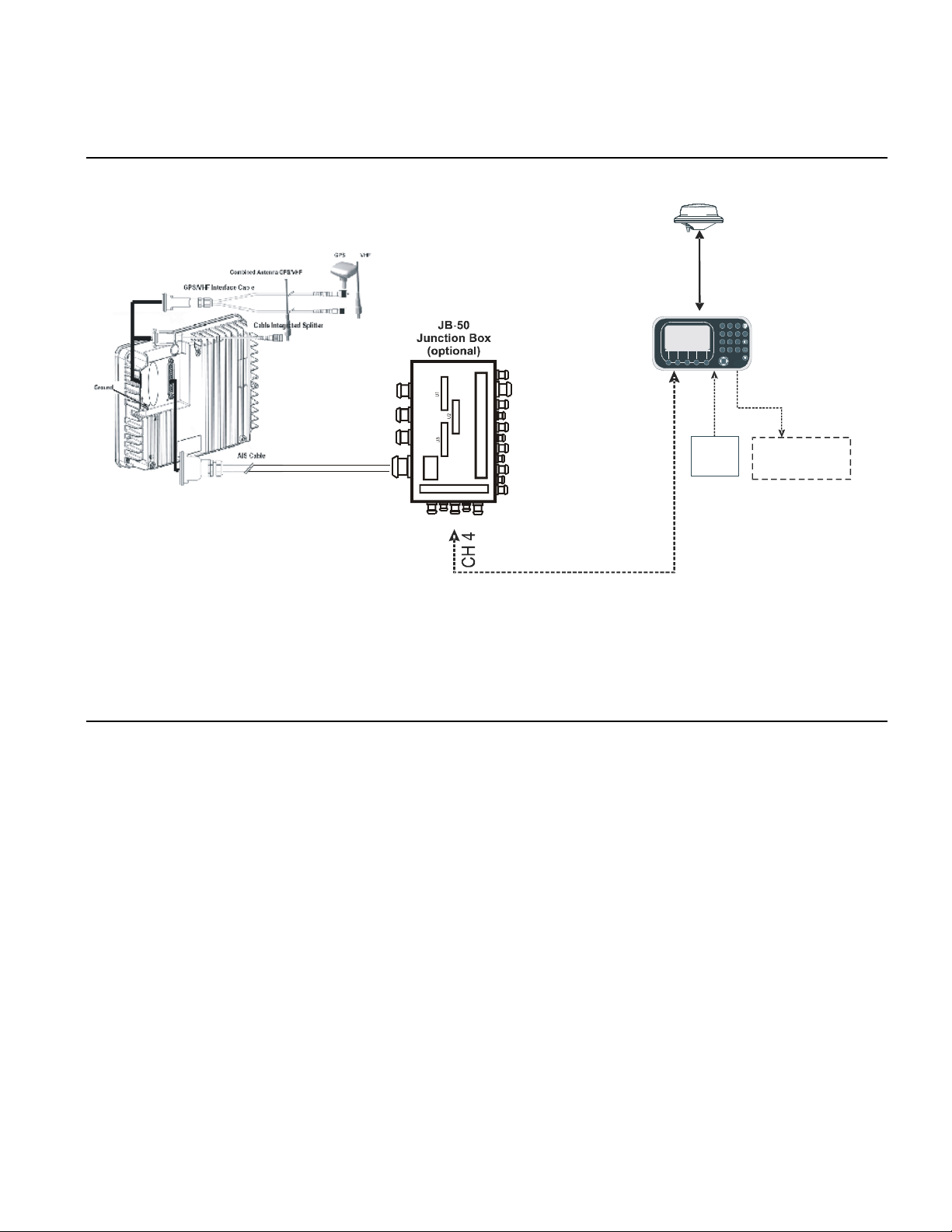
3.2.3 MX535 Connection Diagram
MX-MARINE
SMART DGPS
ANTENNA
(NOT USED FOR MKD).
MX420/AIS
OR
MX420/MKD
Non-MX535
EXT.
ECDIS/ARPA
GPS
Listener
MX420/MX535 communication
Figure 2.3 – MX535 Connection Diagram
Note: The MX535 JB-50 Junction Box (optional) includes a fuse of 6.3A. If it is not used, then the unit has to be
protected against high current by an external slow blow fuse of 6.3A.
3.3 Components and Interfaces
The diagram below illustrates which devices can be connected to the MX535 Transponder. For a detailed
description of sensor connecting e.g. an existing Gyro to MX535, refer to Section 3.4. (2.3) “Sensor Installation” on
page 12-13.
www.mx-marine.com
7
 Loading...