

Page 1

LEICA M / M-P
Instructions
Page 2
5
4
3
2
1
14
13
12
11a
11
10
7
6
2
8
9
15
15a
11c
11b
17
17a
18
16
19
20 39
Page 3
28 29
27
26
25
24
23
22
21
30
31
32
33
34
35
37
36
38
42
41
40
Page 4

Page 5

Leica M / M-P
Instructions
Page 6

EN
FOREWORD
Dear Customer,
Leica would like to thank you for purchasing the LeicaM/M-P and
congratulate you on your choice. With this unique digital view and
range finder camera, you have made an excellent choice.
Foreword
We wish you a great deal of pleasure and success using your new
camera.
In order to make best use of all the opportunities offered by this
high performance camera, we recommend that you first read these
instructions.
Notes:
• Leica is constantly working on developing and optimizing the
LeicaM/M-P. As many functions on digital cameras are
controlled by software, improvements and extensions to the
range of functions may need to be installed on the camera at a
later date. To do this, Leica releases what are known as firmware
updates at irregular intervals.
Cameras are always supplied from the factory with the latest
firmware, but you can easily download the updates to your
camera yourself from our website.
If you register as an owner on the Leica Camera website, you will
receive a newsletter informing you when a new firmware update
is available.
You will find more information on registration and firmware
updates for your camera, as well as changes and additions to
the operating instructions, in the "Customer" area at:
https://owners.leica-camera.com
To check whether your camera is running the latest firmware
version, select Firmware in the main camera menu (page 5,
SETUP section, see p. 154, 225).
• Before using your camera for the first time, please check that
the accessories supplied are complete.
130
Page 7
This is a Class B product based on the standard of the Voluntary Control
Council for Interference from Information Technology Equipment (VCCI).
If this is used near a radio or television receiver in a domestic environ-
ment, it may cause radio interference. Install and use the equipment
according to the instruction manual.
FCC Note: (U.S. only)
This equipment has been tested and found to comply with the limits for a
Class B digital device, pursuant to Part 15 of the FCC Rules. These limits
are designed to
in a residential installation. This equipment generates, uses, and can
radiate radio frequency energy and, if not installed and used in accordan-
ce with the instructions, may cause harmful interference to radio
communications. However, there is no guar antee that interference will not
occur in a particular installation. If this equipment does cause harmful
interference to radio or television reception, which can be determined by
turning the equipment off and on, the user is encouraged to try to correct
the interference by one or more of the following measures:
• Reorient or relocate the receiving antenna.
• Increase the separation between the equipment and receiver.
• Connect the equipment into an outlet on a circuit
which the receiver is connected.
• Consult the dealer or an experienced radio/TV technician for help.
provide reasonable protection against harmful interfer
different from that to
ence
FCC Caution:
To assure continued compliance, follow the attached installation
instructions and use only shielded inter face cables with ferrite core when
connecting to com put er or peripheral devices. Any changes or modifica-
tions not expressly approved by the party responsible for compliance
could void the user’s authority to operate this equipment.
Trade Name: LEICA
Model No.: LEICA M (Typ 240)
LEICA M-P (Typ 240)
Responsible party/
Support contact: Leica Camera Inc.
1 Pearl Count, Unit A
Allendale, New Jersey 07401
Tel.: +1 201 995 0051
Fax: +1 201 995 1684
technicalinfo@leicacamerausa.com
This device complies with Part 15 of the FCC Rules. Operation is subject
to the following two conditions: (1) This device may not cause harmful
interference, and (2) this device must accept any interference received,
including interference that may cause undesired operation.
LEICA M (Typ 240)
LEICA M-P (Typ 240)
Tested To Comply
With FCC Standards
EN
For Canada only:
CAN ICES-3 (B)/NMB-3(B)
FOR HOME OR OFFICE USE
131
Page 8

EN
CONTENTS
Foreword .......................................................................................130
Warning messages .........................................................................134
Legal information ...........................................................................134
Contents
Disposal of electrical and electronic equipment ..............................135
Designation of parts ....................................................................... 136
Quick guide....................................................................................138
Comprehensive instructions
Preparations
Attaching the carrying strap ..................................................... 140
Charging the battery ................................................................141
Replacing the battery and memory card ...................................144
Leica M lenses ........................................................................147
Attaching the lens ................................................................. 149
Detaching the lens ................................................................ 149
The most important settings / Controls
Turning the camera on and off .................................................150
Shutter release button .............................................................151
Serial exposures ...................................................................152
Shutter speed dial ...................................................................153
Menu control ........................................................................... 154
Presets
Basic camera settings
Menu language ........................................................................ 158
Date and time ..........................................................................158
Automatic power off ................................................................160
Signal tones ............................................................................161
Basic picture settings
Lens detection .........................................................................162
Compression rate/file format ..................................................164
Resolution ...............................................................................165
White balance ..........................................................................166
ISO sensitivity .......................................................................... 168
Picture properties / Contrast, sharpness, color saturation .......170
Film styles ...............................................................................171
Working color space ................................................................171
Bright line view and range finder .................................................172
Image field selector ..................................................................174
Monitor ......................................................................................176
Live view mode ...........................................................................176
Horizon ....................................................................................177
132
Page 9

Distance metering ...................................................................178
With the optical range finder .................................................178
With the monitor image in live view mode ...........................180
With indication of in focus subject details ..................................181
Turning the exposure meter on/off ..........................................182
Exposure metering methods ....................................................182
Exposure modes ......................................................................184
Aperture priority ...................................................................184
Exposure lock ....................................................................185
Exposure compensation .....................................................186
Automatic bracketing ............................................................ 188
Manual exposure setting .......................................................190
B setting / T function ...........................................................190
Values above and below the metering range ............................191
Flash mode ..............................................................................192
Additional functions
Video recordings .....................................................................198
Sound recording ......................................................................199
Taking photographs with the self-timer ..................................... 200
Marking the picture files for copyright protection .....................201
Recording the location with GPS ...............................................201
User/application-specific profiles ............................................203
Resetting all custom settings ...................................................205
Review mode ..............................................................................206
Additional functions
Folder management ................................................................. 218
Formatting the memory card .................................................... 220
Transferring data to a computer ............................................... 221
®
Adobe
Photoshop® Lightroom® ..............................................224
Leica Image Shuttle
®
...............................................................224
Working with DNG raw data .....................................................224
Installing firmware updates ......................................................225
Miscellaneous
System accessories ....................................................................226
Spare parts ................................................................................229
Precautions and care instructions
General precautions ...................................................................230
Care instructions ........................................................................ 232
Cleaning the sensor / Dust detection .........................................236
Storage ......................................................................................238
Malfunctions and their resolution ...................................................238
Appendix
Displays .....................................................................................240
Menu items ................................................................................248
Index .............................................................................................250
Technical data ...............................................................................252
EN
Contents
Leica Service addresses ................................................................ 256
133
Page 10

EN
The CE identification of our products documents complies
with the fundamental requirements of the valid EU directives.
WARNING MESSAGES
• Modern electronic components react sensitively to electrostatic
discharge. As people can easily pick up charges of tens of
thousands of volts, by walking on synthetic carpets for example,
a discharge can occur when you touch your camera, particularly
if it is placed on a conductive surface. If only the camera
housing is affected, this discharge is harmless to the electronics.
Warnings / Legal notices
However, despite built-in safety circuits, the outer contacts, such
as the battery or rear panel contacts, should not be touched if at
all possible for safety reasons.
• For any cleaning of the contacts, do not use an optical
micro-fiber cloth (synthetic); use a cotton or linen cloth instead.
Before touching the contacts, you can make sure you discharge
any electrostatic charge by deliberately touching a heating or
water pipe (conductive, earthed material). You can also avoid
soiling and oxidization of the contacts by storing your camera in
a dry place with the lens or bayonet cover fitted.
• You should use exclusively the recommended accessories to
prevent faults, short circuits or electric shock.
• Do not attempt to remove parts of the housing (covers);
specialist repairs can be carried out only at authorized service
centers.
LEGAL INFORMATION
• Please ensure that you observe copyright laws. The recording
and publication of pre-recorded media such as tapes, CDs, or
other published or broadcast material may contravene copyright
laws.
• This also applies to all of the software supplied.
• The SD, HDMI, and USB logos are registered trademarks.
• Other names, company or product names referred to in this
manual are trademarks or registered trademarks of the relevant
companies.
134
Page 11

DISPOSAL OF ELECTRICAL AND
ELECTRONIC EQUIPMENT
(Applies within the EU, and for other European
countries with segregated waste collection systems)
This device contains electrical and/or electronic components and
should therefore not be disposed of in general household waste.
Instead it should be disposed of at a recycling collection point
provided by the local authority. This costs you nothing. If the device
itself contains replaceable (rechargeable) batteries, these must be
removed first and, if necessary, also be disposed of in line with the
relevant regulations.
Further information on this issue is available from your local
administration, your local waste collection company, or in the store
where you purchased this device.
The production date of your camera can be found on the stickers in
the warranty card or on the packaging.
The format is: Year/Month/Day
EN
Disposal of electrical and electronic equipment
135
Page 12

EN
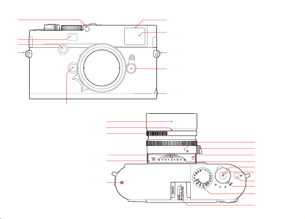
DESIGNATION OF PARTS
Figures in the front and rear cover pages
Front view
1. Lens release button
2. Eyes for carrying strap
3. Focusing button
4. Range finder viewing window
5. Brightness sensor
Designation of parts
6. Viewfinder viewing window
7. Self-timer LED
8. Image field selector
9. Bottom cover locking point
1
Top view
10. Microphone
11. Fixed ring with
a. Index for distance setting
b. Depth of field scale
c. Red index button for changing lenses
12. Aperture setting ring
13. White index point for aperture setting
14. Lens hood
15. Focusing ring with
a. Recessed grip
2
16. Main switch with detent positions for
–
OFF (camera turned off)
–
S (single pictures)
–
C (continuous pictures)
–
(self-timer)
17. Shutter release with
a. Thread for cable release
18. Video shutter release
19. Time setting dial with detent positions for
–
A for automatic shutter speed control
– Shutter speeds
–
B (long-time exposure)
–
Flash sync speed (1/180s)
1
/
- 8s (inc. intermediate values)
4000
20. Flash unit shoe
136
1
Leica M lenses with viewfinder attachment cover the brightness sensor.
Information about functions with these and other lenses can be found under
"Displays / In the viewfinder", p. 240, and "Leica M lenses", p. 147.
1
Only Leica M-P
Page 13

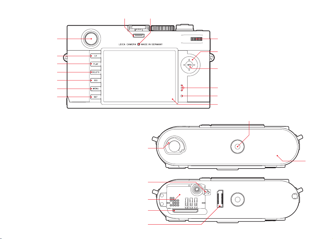
Rear view
21.
SET button
–For calling up the picture parameters menu
–For calling up sub-menus in the menu system
–For applying settings/functions selected in sub-menus
22.
MENU button for calling up and exiting the main menu and
sub-menus
23.
ISO button for calling up the sensitivity setting
24.
DELETE button for selecting the delete function
25.
PL AY button
– For activating (continuous) review mode
– To return to full-screen display
26.
LV button for turning live view mode on and off
27. Viewfinder window
28. Socket for external electronic viewfinder / microphone
1
adapter
(cover removed)
29. Brightness sensor for monitor
30. Setting dial
– For navigating in the menus
– For setting the selected menu options / functions
– For setting an exposure compensation value
– For enlarging/reducing pictures viewed
– For scrolling through the picture memory
31. Direction pad
– For navigating in the menus
– For setting the selected menu options / functions
– For scrolling through the picture memory
32.
INFO button
–For displaying picture settings/data
–For displaying picture data during picture review
–For applying settings
33. Speaker
34. LED for indicating picture mode / recording data
35. Monitor
Bottom view
(with bottom cover fitted)
36. Locking toggle for bottom cover
37. Tripod thread A ¼, DIN 4503 (¼")
38. Bottom cover
(with bottom cover removed)
39. Socket for multifunction M hand grip
1
40. Memory card slot
41. Battery compartment
42. Battery locking slider
EN
Designation of parts
1
Available as accessory, see p. 228
137
Page 14

EN
QUICK GUIDE
Quick guide
YOU WILL NEED THE FOLLOWING ITEMS:
– Camera
– Battery
– Memory card (not supplied)
– Charger and mains cable
138
Page 15

PREPARATIONS
1. Charge the battery (see p. 141)
2. Insert the battery (see p. 144)
3. Insert the memory card (see p. 146)
4. Turn on the camera (see p. 150)
5. Set the menu language (see p. 158)
6. Set the date and time (see p. 158)
7. Format the memory card, if necessary (see p. 220)
TAKING PHOTOGRAPHS
8. Attach the lens (see p. 149)
9. Set the shutter speed dial to A (see p. 153)
10. Set the subject focus (see p. 178)
11. Turn on the camera (see p. 150)
12. Turn on exposure metering (see p. 151)
13. Correct the exposure, if necessary (see p. 186)
14. Release the shutter (see p. 151)
Note:
For details of how to shoot videos, see p. 198.
VIEWING PICTURES
The camera is preset to display the last picture automatically for a
short time (see p. 206).
You can turn on review mode (for an unlimited period) at any time
using the
To view different pictures, press left or right on the direction pad
(see p. 212).
To enlarge the picture turn the setting dial to the right (see p.
213).
PL AY button (see p. 206).
DELETING PICTURES
Press the DELETE button and follow the instructions in the monitor
(see p. 214).
EN
Quick guide
139
Page 16
EN
DETAILED GUIDE
PREPARATIONS
Preparations
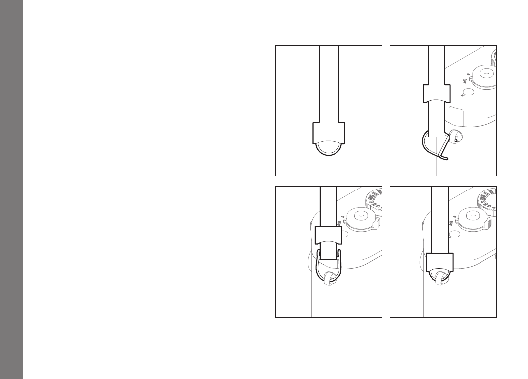
ATTACHING THE CARRYING STRAP
140
Page 17
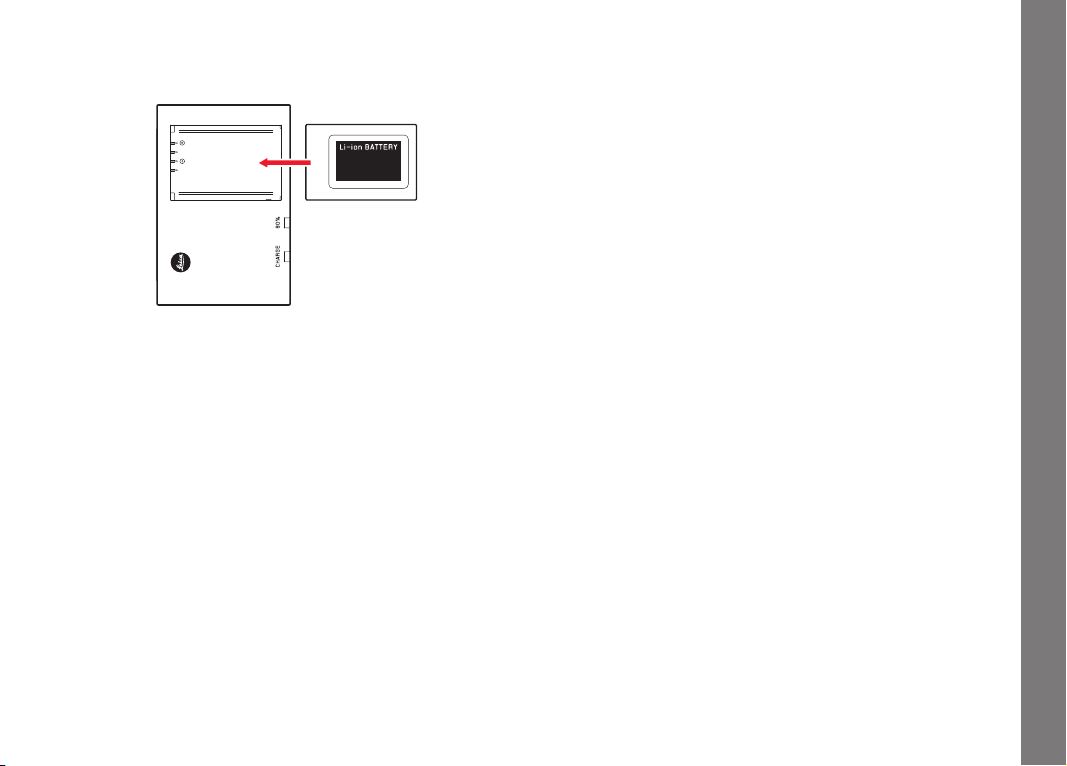
CHARGING THE BATTERY
The camera is powered by a lithium ion battery.
• The green LED marked CHARGE starts fl ashing to confi rm that
charging is in progress. As soon as the battery has charged to at
4
least
/5 of its capacity, the yellow LED marked 80% also lights
up. When the battery is fully charged, the green LED also
changes from fl ashing to continuously lit.
Note:
The
80% LED lights up after around 2 hours due to the charging
characteristics.
The charger should be disconnected from the mains when charging
is complete. There is therefore no risk of overcharging.
EN
Preparations
141
Page 18

EN
Caution:
• Only the battery type specified and described in this manual
(order no. 14 499), or battery types specified and described by
Leica Camera AG, may be used in this camera.
• These batteries may only be used in the units for which they are
designed and may only be charged exactly as described below.
• Using this battery contrary to the instructions and using
Preparations
non-specified battery types can result in an explosion under
certain circumstances.
• The batteries must not be exposed to heat, sunlight, humidity or
moisture for long periods. Likewise, the batteries must not be
placed in a microwave oven or a high pressure container as this
results in a risk of fire or explosion.
• A safety valve in the battery guarantees that any excess pressure
caused by improper handling is discharged safely.
• Only the charger specified and described in this manual (order
no. 14 494) is to be used. The use of other chargers not
approved by Leica Camera AG can cause damage to the
batteries and, in extreme cases, can cause serious or lifethreatening injuries.
• The charger supplied should be used exclusively for charging this
battery type. Do not attempt to use it for other purposes.
• The car charging cable supplied must never be connected while
the charger is connected to the mains.
• Ensure that the mains outlet used for charging is freely
accessible.
• The battery and charger must not be opened. Repairs may only
be carried out by authorized workshops.
142
Page 19

Notes:
• The battery should be charged before the camera is used for the
first time.
• The battery must have a temperature of 10°-30°C to be charged
(otherwise the charger will not turn on, or will turn off again).
• Lithium ion batteries can be charged at any time, regardless of
their current charge level. If a battery is only partly discharged
when charging starts, it is charged to full capacity faster.
• The batteries warm up during the charging process. This is
normal and not a malfunction.
• If the two LEDs on the charger flash rapidly (> 2Hz) after starting
charging, this indicates a charging error (e.g. maximum charging
time exceeded, voltages or temperatures outside the permitted
ranges, or short circuit). In this case, disconnect the charger
from the mains and remove the battery. Ensure that the above
temperature conditions are met and then restart the charging
process. If the problem persists, please contact your dealer, the
Leica office in your country or Leica Camera AG.
• A new battery only reaches its full capacity after it has been fully
charged and – by use in the camera - discharged again 2 or 3
times. This discharge procedure should be repeated every 25
cycles. To ensure a maximum service life of the battery, it should
not be exposed to constant extremes of temperature (e.g. in a
parked car in the summer or winter).
• Even when used in optimum conditions, every battery has a
limited service life. After several hundred charging cycles, this
becomes noticeable as the operating times get significantly
shorter.
• The battery should be replaced after a maximum of four years,
as its performance deteriorates and reliable operation can no
longer be guaranteed, particularly in cold conditions.
• Defective batteries should be disposed of according to the
respective instructions (see p. 233).
• The replaceable battery provides power to a back-up battery
which is permanently fitted in the camera. This back-up battery
retains the set date and time for up to 2 months. If this back-up
battery becomes discharged it must be recharged by inserting
the replaceable main battery. Once the replaceable battery has
been inserted, the full capacity of the back-up battery is
recovered after about a few days. This process does not require
the camera to be turned on.
EN
Preparations
143
Page 20
EN
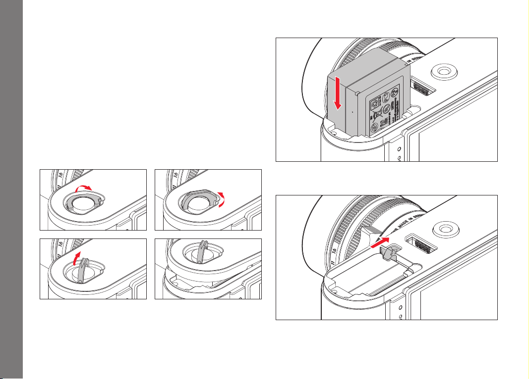
REPLACING THE BATTERY AND MEMORY CARD
Set the main switch (16) to
Important:
Do not open the bottom cover or remove the memory card or
battery whilst the red LED (34) at the bottom right next to the
monitor (35) is fl ashing, indicating picture recording and/or data
Preparations
saving to the card. Otherwise the unsaved (or not completely
saved) picture data may be lost.
Removing the bottom cover
OFF.
Inserting the battery
Removing the battery
144
Page 21

Charge level displays
In picture mode, the battery charge level is displayed in the monitor
(35) by pressing the
Notes:
• Remove the battery if you will not be using the camera for a long
period of time.
• A maximum of 2 months after the capacity of a battery left in
the camera is exhausted (see also the last note under “Charging
the battery”, p. 143), the date and time need to be re-entered.
• As the battery capacity deteriorates or if using an older battery,
depending on the function being used warning messages and
displays may appear and functions may be restricted or blocked.
INFO button (32).
Compatible memory cards
The camera saves the pictures on an SD (secure digital), SDHC
(high capacity), or SDXC (eXtended capacity) card.
SD/SDHC/SDXC memory cards are available from various
suppliers and with diff erent capacities and read/write speeds.
Particularly those with high capacities and read/write speeds allow
data to be recorded and retrieved very quickly. The cards have a
write protection switch, which can be used to prevent unintentional
storage and deletion of pictures. This switch takes the form of a
slider on the non-beveled side of the card; in the lower position,
marked LOCK, the data on the card is protected.
Note:
Do not touch the memory card contacts.
EN
Preparations
145
Page 22
EN
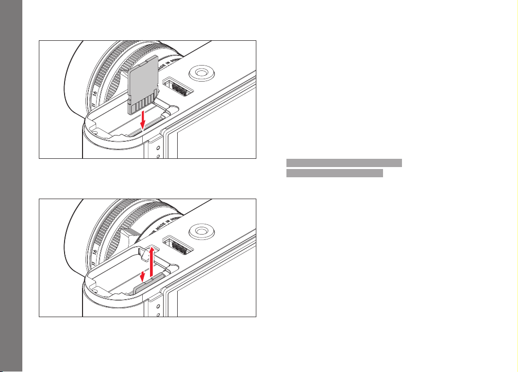
Inserting the memory card
Preparations
Removing the memory card
Notes:
• The range of SD/SDHC/SDXC cards is too large for Leica Camera AG
to be able to completely test all available types for compatibility
and quality. Although using other card types is not likely to
damage the camera or the card, some "no name" cards do not
comply with the SD/SDHC/SDXC standards, and Leica Camera
AG is unable to provide any guarantee that they will function
correctly.
• Video recordings in particular require a high write speed.
• If the memory card cannot be inserted, check that it is aligned
correctly.
• If you remove the bottom cover or take out the memory card
when the camera is turned on, the monitor displays the
corresponding warning messages instead of the normal displays:
–
Attention Bottom cover removed
– Attention No card inserted.
• As electromagnetic fi elds, electrostatic charges, and defects on
the camera or the card can lead to damage or loss of the data
on the memory card, we recommend that you also transfer the
data to a computer and save it there (see p. 221).
• For the same reason, it is recommended that the card is always
stored in its antistatic cover.
146
Page 23
LEICA M LENSES
Generally speaking, most Leica M lenses can be used. Details on
the small number of exceptions and restrictions can be found in
the following notes.
They can be used regardless of the lens features, and whether it
does or does not have 6-bit coding in the bayonet.
Even without this additional feature, i.e. when using Leica M lenses
without identifi cation, the camera will deliver excellent pictures in
most situations.
To ensure optimum picture quality in these situations, we
recommend entering the lens type (see p. 163).
Important:
• The following cannot be used:
– Hologon 15mm f/8
– Summicron 50mm f/2 with close up.
– Elmar 90mm f/4 with retractable tube (manufactured from
1954-1968)
– Some versions of the Summilux-M 1.4/35mm (not aspherical,
manufactured from 1961-1995, Made in Canada) cannot be
fi tted to the camera or will not focus to infi nity. The Leica
Customer Care department can modify these lenses so that
they can be used on the camera.
• The following can be used, but risks damaging the camera or
lens:
Lenses with retractable tube can only be used with the tube
extended, i.e. their tube must never be retracted into the
camera. This is not the case with the current Macro-Elmar-M
1:4/90mm, as its tube does not protrude into the camera body
even when retracted. It can therefore be used without any
restrictions.
EN
Preparations
147
Page 24

EN
• The following can be used with restrictions
Despite the high precision of the range finder on the camera,
exact focusing with 135mm lenses with an open aperture
cannot be guaranteed due to the very low depth of field.
Therefore, stopping down by at least 2 stops is recommended.
By contrast, live view mode (see p. 176) and the various setting
Preparations
facilities allow unrestricted use of this lens.
• The following can be used, but are excluded from
exposure metering (see p. 182)
– Super-Angulon-M 21mm f/4
– Super-Angulon-M 21mm f/3.4
– Elmarit-M 28mm f/2.8 with serial nos. before 2 314 921.
Notes:
• The Leica Customer Care department can upgrade many Leica
M lenses with 6-bit coding (for address, see p. 256).
• In addition to Leica M lenses with and without coding, using the
Leica M adapter R available as an accessory (see p. 226) Leica
R lenses can also be used.
Classic
148
Page 25
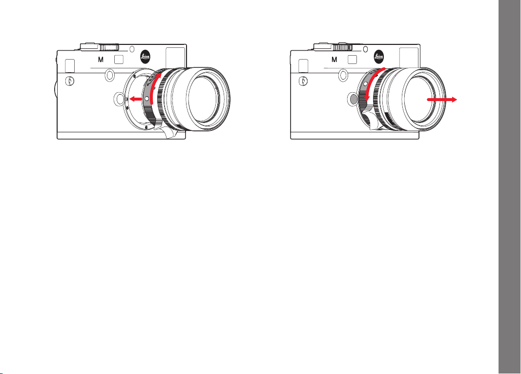
Attaching the lens
Detaching the lens
EN
Preparations
1. Turn off the camera.
2. Hold the lens by the fi xed ring (11).
3. Align the red index button (11c) on the lens with the release
button (1) on the camera housing.
4. In this position, insert the lens.
5. Turn the lens slightly to the right, and you will hear and feel it
click into place.
1. Turn off the camera.
2. Hold the lens by the fi xed ring (11).
3. Press down the release button (1) on the camera body.
4. Turn the lens to the left until its red index button (11c) is
aligned with the release button.
5. Remove the lens.
Notes:
• Generally: To protect the Leica T against ingress of dust etc. into
the interior of the camera, it is important always to have a lens
or a cover fi tted to the camera body.
• For the same reason, when changing lenses work quickly and in
an environment that is as dust-free as possible.
• Camera or lens rear covers should not be stored in your pants
pocket as they attract dust that can get into the camera when
they are fi tted.
149
Page 26
EN
THE MOST IMPORTANT SETTINGS / CONTROLS
TURNING THE CAMERA ON AND OFF
Camera operation
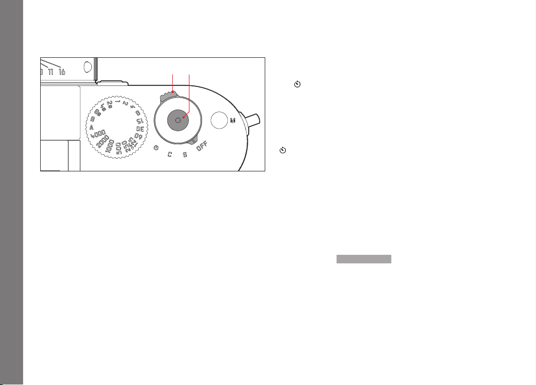
16 17
c. C - Continuous series
A series of pictures are taken for as long as the shutter release
is held down and the capacity of the memory card used and
the internal buff er memory is suffi cient. The fi rst 16 pictures at
least are taken in rapid succession, subsequent pictures with a
reduced frequency.
d.
- Self-timer
Pressing the shutter release starts the set delay time (see p.
200), then the picture is taken.
TURNING ON
After turning on, i.e. after setting one of the three functions
, the LED (34) lights up briefl y and the displays in the viewfi nder
appear (see p. 240).
S, C or
150
The camera is turned on and off using the main switch (16). This is
below the shutter release (17) and is a lever with four detent
positions:
a.
OFF – Camera turned off
b.
S – Single picture
Pressing the shutter release takes a single picture regardless
of how long it is held down for.
Note:
After turning on, the camera is ready to use after approx. 1s.
TURNING OFF
Even if the main switch is not set to
OFF, the camera is
automatically turned off if an automatic power off time has been
set in the menu (
Auto P ower Off , see p. 160) ), and none of the
controls are used in this time.
Page 27

Note:
If the camera is out of use for an extended period or is stored in a
case, always turn it off at the main switch. This prevents any power
consumption, including that which continues to occur in standby
mode after the exposure meter is turned off automatically and the
display is extinguished. This also prevents pictures from being
taken accidentally.
THE SHUTTER RELEASE BUTTON
The shutter button (17) has two pressure points:
1. Pressing down to the 1st pressure point
– activates exposure metering and the viewfinder display
– saves the metered exposure value in aperture priority mode, i.e.
the shutter speed determined by the camera (for more details,
refer to the “Metering memory lock” section on p. 185)
– restarts a self-timer delay time that is already in progress
(see p. 200)
If the shutter button is kept at this pressure point, the displays
remain visible, or if the camera had previously been set to review
mode, it switches back into picture mode. If the camera had
previously been in stand-by mode, it will be reactivated and the
displays switched on.
If you let go of the shutter button, the metering system and the
displays remain activated for around a further 12s (for more details,
refer to the sections on p. 182).
Note:
The shutter button remains blocked
– if the internal buffer memory is (temporarily) full, e.g. after a
series of ≥16 pictures, or
– if the memory card inserted and the internal buffer memory are
(temporarily) full, or
– if the battery has exceeded its performance limits (capacity,
temperature, age)
2. Pressing the shutter button all the way down takes the picture
or starts a preselected self-timer delay time. The data is then
transferred to the memory card.
The shutter button has a standard thread (17a) for a cable release.
Notes:
• If review mode (see p. 206) or menu control (see p. 154) had
been activated, pressing the shutter button causes the camera
to switch immediately into picture mode.
• To avoid wobble, the shutter button should be pressed gently,
not jerkily, until the shutter is released with a soft click.
• The shutter button can be pressed to take one or more individual
pictures while a video recording is in progress. Details of video
recordings and the video shutter button (18) can be found on
p.198.
EN
Camera operation
151
Page 28

EN
Serial exposures
You can not only take single pictures - by setting the main switch
(16) to (
S (single) - but also series of pictures, by setting the main
switch to
C (continuous), e.g. to capture sequences of movement
in several stages.
Apart from operation of the shutter button (17), series of pictures
are taken in the same way as single pictures: A series of pictures is
taken for as long as you hold down the shutter button (provided
that the memory card has suffi cient capacity). If you only press it
Camera operation
briefl y, the camera continues to take single pictures.
A maximum of around 3 frames per second can be produced. At
least the fi rst 16 of these are taken in rapid succession, after
which the image frequency is reduced slightly.
Notes:
• The specifi ed picture frequency and the maximum possible
number of pictures in a series relate to a default setting –
200 and JPEG fine format. The frequency and number may be
ISO
lower when using diff erent settings or depending on the memory
card used.
• Regardless of how many pictures have been taken in a series,
both review modes (see p. 206) initially show the last picture in
the series or the last picture in the series saved on the currently
active card, if not all of the pictures in the series have been
transferred from the internal buff er memory to the relevant card
yet.
152
Page 29
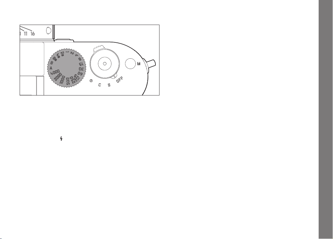
SHUTTER SPEED DIAL
The exposure modes are selected using the shutter speed dial (19),
– aperture priority mode by setting the
A position marked red (see
p. 183),
– manual mode by selecting a shutter speed of
1
/
s to 8s
4000
(intermediate values in ½ step positions are also available);
– the shortest possible sync speed of
marked with the
–
B for long exposures (see p. 190).
symbol (see p. 193), and
1
/
s for fl ash mode,
180
The Leica M shutter speed dial has no stop, i.e. it can be turned in
either direction from any position. It detents at all marked positions
and at the intermediate values. Values between the detent
positions cannot be used. More details on setting the correct
exposure can be found in the sections p. 182.
EN
Camera operation
153
Page 30

EN
MENU CONTROL
Many settings for the camera are controlled using either of two
separate menus (see p. 248/249).
The split into two menus and the grouping in the main menu allows
what experience has shown to be the most frequently used options
to be called up and set quickly and easily.
When the camera is turned on, an overview of the relevant settings
and step-by-step instructions for setting these options can be
viewed in the monitor (35).
Camera operation
Settings are made in the same way in both menus, the differences
are only in calling up and exiting them.
MAIN MENU
The main menu is made up of 35 options. It is divided into 3
function groups:
–
CAMERA (basic camera settings – page 1)
–
IMAGE (picture settings – page 2)
–
SETUP (supplementary functions – pages 3-5)
PICTURE PARAMETERS MENU
The picture parameters menu is made up of 8 options. In addition
to basic picture settings, it contains two options relating to
exposure metering and control and one that can be used to create
and call up user profiles.
154
Page 31

Setting the menu functions
1. The main menu is called up using the
the picture parameters menu using the
• The first =
CAMERA page containing the first 6 options then
MENU button (22), and
SET button (21).
appears in the main menu, and all options in the picture
parameters menu.
The active option when a page is selected is always the last
one to be changed.
Note:
The picture parameters menu is only accessible when the camera
is in picture mode.
EN
Camera operation
155
Page 32

EN
2. You can select the relevant option either using the setting dial
(30; turn right = down in menu, turn left = up in menu) or the
direction pad (31; press up or down).
Camera operation
Notes:
• Using the setting dial is normally not only more convenient but
also significantly faster.
• Some options, such as
GPS and Format SD Card, as well as
some sub-menu options, can only be called up in certain
situations. Further explanations can be found in the relevant
sections.
• This is indicated by the lettering in the corresponding lines being
grayed out.
3. You can select the relevant sub-menus with both the
button and the
INFO button (32) or by pressing right on the
SET
direction pad.
• The displays in the header change: The associated function
group is shown in black on the left (
SETUP in the main menu, always SET in the picture
CAMERA , IMAGE or
parameters menu), with the selected menu option in white
on the right.
The sub-menus usually consist of different numbers of
function options, which can be directly selected in the next
step.
In some cases, there is also a scale for setting values, or the
sub-menus consist of secondary entries for which function
options can be selected in turn.
156
Page 33

4. Select the relevant function option / value, either using the
setting dial or by pressing the corresponding direction on the
direction pad, i.e.
– up/down to change lines or to select options
– left/right for settings within a line or on a scale
For sub-entries with selectable options, it is also possible to
change line using the
INFO button.
• The displays in the header change again: The sub-entry is
specified in black on the left, with the selected option in
white on the right.
Note:
Options such as
White balance functions require additional settings. The
Date/Time and the Exposure bracketing and
corresponding explanations, as well as further details about the
other menu functions, can be found in the relevant sections.
5. Save your setting using the
SET or INFO button.
• The monitor screen reverts to its initial condition. The new
function option set is then shown on the right of the
corresponding menu line.
Note:
You can exit the menus and sub-menus at any time - without
applying the settings made - by pressing the following buttons:
Shutter button/
Video shutter
PL AY
(25):
MENU
(22):
release
(17/18)
Main menu
Picture
parameters
menu
Camera switches
to picture mode
Camera switches
to picture mode
Camera
switches to
review mode
Camera
switches to
review mode
One step back (e.g.
to previous menu
level)
One step back (e.g.
to previous menu
level), or return to
main menu
EN
Camera operation
157
Page 34

EN
PRESETS
DATE AND TIME
These entries can be made by selecting
Date / Time in the menu.
BASIC CAMERA SETTINGS
MENU LANGUAGE
The camera is set to English by default. German, French, Italian,
Spanish, Russian, Japanese, Korean and Traditional or Simplified
Chinese can all be selected as alternative menu languages.
Basic camera settings
Setting the function
1. In the main camera menu, (see p. 154/248) select
Language
(page 5,
SETUP section), and
2. select the desired language in the sub-menu.
• Apart from a few exceptions (button names, short designations), all linguistic information changes.
Setting the functions
1. In the main camera menu, (see p. 154/248) select
Date / Time
(page 5,
SETUP section), and
2. call up the sub-menu. This is made up of the three options
Auto Time/Time Zone , Date and Time .
Automatic time display controlled by GPS
This option is only available if the multifunction M hand grip is
attached (available as accessory, see p. 228).
3. Select
4. In this sub-menu, select
5. set the preferred option (
Auto Time/ Time zone.
• A further sub-menu appears, containing the options
time via GPS (only available if the GPS function is activated
in the menu, see p. 201) ),
Time zone and Summer time.
Auto time via GPS , and
On /Off).
Auto
If this function is activated, the time set on the camera is updated
continuously based on GPS signals received.
158
Page 35

For correct time display anywhere in the world:
6. In the same sub-menu select
Time zone, and
7. Select the relevant zone / your current location.
• The current set difference from Greenwich Mean Time is
shown on the right of the line, with large cities and the
current time in the relevant time zones below.
Entering the correct time in countries with seasonal time
changes:
8. In the same sub-menu select
9. set the preferred option (
Summer time, and
On /Off).
Note:
Time zone and Summer time are only available when the Auto time
via GPS function is deactivated.
DATE
There are 3 options available for the sequence of the date.
3. In the
4. Select
5. In the
Date / Time sub-menu, select Date. It contains the 2
options
Format and Setting.
Format.
Format sub-menu, select which of the 3 possible
sequences you want to use:
Year, or Year/Month/Day.
Day/Month/ Year, Month/Day/
6. Save your setting.
• The
Date sub-menu appears again.
7. Select
Setting.
• A further sub-menu appears, with columns for the year and
day figures and for the month names. The currently active,
i.e. editable, column is indicated by red underlining, with the
heading in white and the figures and names that can be set
in red.
Use the setting dial (30) or the direction pad (31) to set the
numbers / months and the
SET button (21), the INFO button
(32) or the direction pad to switch between the columns.
8. After making the setting, confirm all 3 headings and save
them.
EN
Basic camera settings
159
Page 36

EN
TIME
The time can either be shown in 24-hour or 12-hour format.
Both the display format and the actual figures are set using the
Time option, essentially in exactly the same way as described for
Date in the previous section.
Note:
Even if no battery is inserted or the battery is flat, an integrated
back-up battery retains the date and time setting for around 2
months. After this time the date and time must be set again as
Basic camera settings
described above.
AUTOMATIC POWER OFF
This function turns the camera off automatically after a preset
time.
Setting the function
1. In the main camera menu, (see p. 154/248) select
Auto P ower Off
(page 5,
SETUP section).
2. Now select the desired time.
Note:
Even if the camera is in standby mode, i.e. the displays have gone
out after 12s or the activated
Auto P ower Off function has turned
it off, it can be reactivated at any time by pressing the shutter
button (17).
160
Page 37

SIGNAL TONES
You can decide whether you want warning messages that appear in
the monitor and the self-timer countdown to be accompanied by an
acoustic signal – two volumes are available - or whether operation
of the camera should be largely silent.
Note:
The factory default setting for signal tones is
Off.
Setting the functions
1. In the main camera menu, (see p. 154/248) select
Acoustic Signal
(page 5,
SETUP section).
2. You can now select
Off, Low or HIgh.
EN
Basic camera settings
161
Page 38

EN
BASIC PICTURE SETTINGS
LENS DETECTION
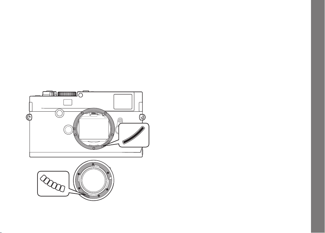
The 6-bit coding in the bayonet fastening of current Leica M lenses
allows the camera to identify the type of lens fitted using the
sensor in the bayonet socket.
– Among other things, this information is used to optimize the
picture data. Thus edge darkening which can be noticeable with
Basic picture settings
wide-angle lenses and large apertures can be compensated in
the corresponding picture data.
– Flash exposure and reflector control also use the lens data (see
"Compatible flash units", p. 192).
– In addition, the information provided by this 6-bit coding is
written to the EXIF data for the picture. When displaying
extended image data, the lens focal length is also shown (see p.
247).
Setting the function
1. In the main camera menu, (see p. 154/248) select
Lens Detection
(page 1,
CAMERA section), and
2. select the desired option in the sub-menu:
–
Off, or
–
Automatic, if a coded lens is attached, or
–
Manual , if a non-coded lens is attached.
Note:
When using lenses without 6-bit coding, the identification function
must be deactivated to prevent malfunctions, or the lens type used
must be entered manually (see p. 163).
162
Page 39

MANUAL LENS TYPE / FOCAL LENGTH ENTRY
The camera is unable to recognize previous Leica M lenses as they
have no identification. However, this "identification" can be carried
out in the menu.
The same applies to Leica R lenses, which can be used on the
camera with a Leica R adapter M (for further details, refer to the
adapter manual).
3. Select the lens you are using from the list in the
sub-menu.
• The monitor shows a list of lenses, which also includes the
relevant item numbers to ensure clear identification. The
camera detects whether an M lens is attached, or a Leica R
lens using the adapter. The list contains either only M or
only R lenses accordingly.
Manual
Notes:
• On many lenses, the item number is engraved on the reverse
side of the depth of field scale.
• The list contains lenses that were available without coding (prior
to around June 2006). Lenses introduced more recently are only
available with coding and therefore cannot be selected manually.
• When using the Leica Tri-Elmar-M 16-18-21mm f/4 ASPH, the
set focal length is not transferred to the camera and thus is not
included in the EXIF data for pictures. If required, you can enter
the relevant focal length manually.
• By contrast, the Leica Tri-Elmar-M 1:4/28-35-50mm ASPH
features mechanical transfer of the set focal length to the
camera, necessary to display the appropriate bright line frame in
the viewfinder. It is detected by the camera electronics and used
for focal length specific compensation. However, only one item
number - 11 625 - is listed in the menu for reasons of space. Of
course, the other two versions - 11 890 and 11 894 - can be
used and the settings made in the menu also apply to them.
EN
Basic picture settings
163
Page 40

EN
COMPRESSION RATE / FILE FORMAT
The picture data is recorded either
a. using one of two different JPEG compression rates:
JPEG standard , or
b. in the
DNG file format, either compressed or uncompressed, or
c. using combinations of one of the two JPEG compression rates
and the set DNG format, i.e. two files are generated per
picture.
On the one hand this allows you to take account of the intended
usage and the available memory card capacity, and on the other
Basic picture settings
hand provides the security and flexibility essential for deciding on
the usage later.
Setting the function
Selecting the JPEG compression or format combination
1. In the picture parameters menu (see p. 154/248) select
File format , and
2. in the respective sub-menu, select the desired compression/
combination.
JPEG fine /
Selecting the DNG compression
1. In the main camera menu, (see p. 154/248) select
DNG Compression
(page 2,
IMAGE section), and
2. select the desired option in the relevant sub-menu (
=compressed /
Off =uncompressed).
On
Notes:
• The standardized DNG (Digital Negative) format is used for
storage of completely unprocessed raw picture data.
• The available compression for DNG format
– is lossless, i.e. it does not cause any deterioration in quality
– retains all of the post-editing performed on the image data
– allows faster saving
– takes up less memory space.
• If simultaneous storage of picture data as DNG and JPEG is
selected, the existing resolution setting is used for the JPEG
format, i.e. the resolutions of the two files can be quite different.
• A high compression rate such as for
JPEG standard can result
in very fine structures in the subject being lost or incorrectly
reproduced (artifacts; e.g. “stepped” diagonal edges).
• The remaining number of pictures shown in the monitor does not
necessarily change after every picture. This depends on the
subject; with JPEG files very fine structures result in higher
quantities of data, homogeneous surfaces in lower quantities.
164
Page 41

RESOLUTION
The picture data can be recorded in JPEG format at four different
resolutions. This allows you to adjust the setting precisely to the
intended use or to the available memory card capacity. At the
highest resolution (which also means the largest data volume),
which you should select for optimum quality for large prints, a card
can hold significantly fewer pictures than at the lowest resolution.
Setting the function
1. In the picture parameters menu (see p. 154/248) select
JPEG Resolution, and
2. select the desired resolution in the sub-menu.
Note:
In DNG format, the resolution is 24MP, i.e. regardless of any
different setting made for JPEG format.
EN
Basic picture settings
165
Page 42

EN
WHITE BALANCE
In digital photography, white balance ensures neutral rendition of
color in any light. It is based on the camera being preset to
reproduce a particular light color as white.
You can choose from ten different settings:
–
Automatic – for automatic control, which delivers neutral
results in most situations.
– Seven fixed presets for the most frequent light sources:
–
Daylight - e.g. for outdoor pictures in sunshine.
–
Basic picture settings
Cloud - e.g. for outdoor pictures with cloudy skies.
–
Shadow - e.g. for outdoor pictures with the main subject
in shadow.
–
Artificial light - e.g. for indoor pictures with (prevailing)
incandescent lamp light.
–
Warm fluorescent - e.g. for indoor pictures with
(prevailing) light from fluorescent tubes, for example for
homes with warm light similar to incandescent lamps at
approx. 2700K.
–
Cool fluorescent - e.g. for indoor pictures with (prevailing)
light from fluorescent tubes, for example for working areas
and external lighting with cool light at approx. 4000K.
–
Flash - e.g. for pictures with electronic flash lighting.
–
Gray card – for manual setting by metering.
–
Color temperature
1
– for a directly adjustable color
temperature value.
Note:
Setting to Automatic allows the white balance to be adjusted for
correct color reproduction when using an electronic flash unit that
satisfies the technical requirements of System 3000 System
Camera Adaption (SCA) and has an SCA-3502 adapter or a
corresponding integrated foot.
However, if other flash units are used, which are not specially
designed for the camera and do not automatically adjust the white
balance, the
Flash setting should be used.
Setting the function
For automatic or fixed settings
1. In the picture parameters menu (see p. 154/248) select
White Balance, and
2. select the desired function in the sub-menu.
166
1
All color temperatures are specified in Kelvin.
Page 43

For direct setting of color temperature
1
You can directly set values between 2000 and 13100 (K
) (from
2000 to 5000K in increments of 100, from 5000 to 8000K in
increments of 200 and from 8000 to 13,100K in increments of
300). This provides you with a broad scope, covering almost all
color temperatures that can occur in practice and within which you
can adapt the color reproduction very sensitively to the existing
light color and/or your personal preferences.
1. In the picture parameters menu (see p. 154/248) select
White Balance, and
2. in the sub-menu select the
Color temperature option.
3. Use the setting dial (30) or press up/down on the direction
pad (31) to select the desired value, and
4. confirm your setting with the
INFO (32) or SET button (21).
For manual setting by metering
1. In the picture parameters menu (see p. 154/248) select
White Balance, and
2. in the sub-menu select the
• The message
white balance. appears in the monitor.
Please take a picture for setting the
Gray card option.
3. Take the picture, making sure that the image field contains a
white or neutral gray (reference) surface.
• The monitor shows
– the image based on the automatic white balance setting,
– cross hairs in the center of the image.
4. Press the direction pad in the desired direction to move the
cross hairs to the subject detail you want to use as the basis
for the new white balance setting (e.g. the reference surface
mentioned above).
5. Press the
INFO button.
• The reproduction of color in the image is adjusted
accordingly.
6. You can now either
– apply this new white balance setting, by pressing the
SET
button,
• the message
White balance set appears in the monitor,
– or make any number of further settings, as described under
4 - 5.
A value set in this way remains saved for and will be used for all
pictures until it is superseded by a new metered value or you use
one of the other white balance settings.
Note:
In parallel to a saved white balance setting, the picture is saved
with the corresponding color reproduction instead of the original
picture.
EN
Basic picture settings
167
Page 44

EN
ISO SENSITIVITY
The ISO setting covers a range of ISO 200 – 6400 in
increments, and thus enables you to adapt the shutter speed/
aperture values to the relevant situation as required. The
setting has the same brightness as a sensitivity of ISO 100.
However, pictures taken using this setting have a lower contrast
range. When using this sensitivity setting, it is important to make
sure that important parts of the image are not overexposed.
As well as the fixed settings, the camera also features the
function, in which the camera automatically adjusts the sensitivity
Basic picture settings
to the ambient brightness and the shutter speed/aperture settings.
In conjunction with aperture priority mode (see p. 184) this
extends the range for automatic exposure control. A manual setting
provides more flexibility for using the desired shutter speed/
aperture combination.
However, when using the function it is also possible to specify
priorities, for example for compositional reasons.
Note:
Particularly at high ISO values and when editing pictures, noise as
well as vertical and horizontal stripes may become visible,
especially in large, uniformly bright areas of the subject.
Accordingly, these features are identified by the suffix
1
/3 ISO
Push.
Pull 10 0
1
Auto
Setting the function
With the
1. Press the
ISO button
ISO button (23).
• The corresponding sub-menu appears in the monitor (34).
2. While holding down the
ISO button, use the setting dial (30) to
select the desired sensitivity or the automatic setting.
Note:
When you release the
ISO button, the sub-menu remains visible for
around 2s. However, the set value is applied immediately.
Using the menu
1. In the picture parameters menu (see p. 154/248) select
ISO , and
2. use the setting dial (30) or press up/down on the direction
pad (31 to set the desired sensitivity or select the automatic
setting.
3. confirm your setting with the
INFO (32) or SET button (21).
To set the sensitivity automatically
3. In the 2nd step, select
Auto .
• The previously grayed-out (unavailable) sub-menu options
are now enabled.
168
1
The function is not available when using flash units.
Page 45

Note:
By factory default, the
Maximum ISO function is limited to ISO 800.
To restrict the automatic setting range
4. In this sub-menu, select
exposure time..
5. In the
Maximum AUTO ISO sub-menu, select the highest
Maximum AUTO ISO and/or Maximum
sensitivity to be used, and thus the range within which the
automatic setting will operate, or in the
exposure time sub-menu select either one of the focal
Set maximum
length-specific settings - 1/focal length, 1/[2xfocal length], 1/
[4xfocal length]
2
if you want to leave it up to the camera to
ensure blur-free shutter speeds, or select the slowest shutter
speed you want to specify (1/2s - 1/500s, in whole steps). In
the focal length-specific settings, the camera only switches to
a higher sensitivity if the shutter speed would fall below the
threshold due to lower brightness, e.g. with a 50mm lens at
slower speeds than 1/60s at 1/focal length, or 1/125s at 1/
[2xfocal length], or 1/250s at 1/[4xfocal length].
6. confirm your setting with the
INFO (32) or SET button (21).
Specifying AUTO ISO mode in manual exposure setting
4. In this sub-menu select
Previous ISO.
5. If you select
On, automatic control is active (where appropriate
within the limit you specified in the
AUTO ISO in M mode, and then On or
Maximum AUTO ISO
sub-menu item). If you select Previous ISO., the last manually
set sensitivity will be used.
6. confirm your setting with the
INFO (32) or SET button (21).
Note:
The following rule applies when using automatic bracketing (see p.
188):
The sensitivity automatically determined by the camera for the
uncorrected picture is also used for all other pictures in a series,
i.e. this ISO value is not changed during a series. This may mean
that the slowest shutter speed specified under
exposure time is exceeded.
Set maximum
EN
Basic picture settings
2
This function requires the use of coded lenses or setting of the lens type used in
the menu (see p. 163).
169
Page 46

EN
The functions and settings described in the next two sections refer
exclusively to pictures in one of the JPEG formats. If one of the two
DNG formats is specified, these settings have no effect, as in this
case the picture data is always saved in its original form.
PICTURE PROPERTIES / CONTRAST, SHARPNESS, COLOR
SATURATION
In digital photography, key picture properties can be changed very
easily. While photographic software – after recording and transfer
to a computer – provides great scope for doing this, the camera
Basic picture settings
itself allows you to influence three of the most important picture
properties even before taking the picture:
• The contrast, i.e. the difference between light and dark areas,
determines whether a picture has a more “matt” or “glossy”
effect. As a consequence, the contrast can be influenced by
increasing or reducing this difference, i.e. by lighter reproduction
of light sections of the image and darker reproduction of dark
sections.
• Sharp reproduction – at least of the main subject – using the
correct distance setting is a prerequisite for a successfully
picture. In turn, the impression of sharpness of a picture is to a
great extent determined by the sharpness of the edges, i.e. by
how small the transition area between light and dark is at the
edges in the picture. The impression of sharpness can thus be
changed by expanding or reducing these areas.
• The color saturation determines whether the colors in the
picture tend to appear as "pale" and pastel-like or "bright" and
colorful. While the lighting and weather conditions (hazy/clear)
are given as conditions for the picture, there is definite scope for
influencing the reproduction.
• All three picture properties can be adjusted – independently - to
five different levels using the menu, so that you can set the
optimum values for any situation, i.e. the prevailing lighting
conditions.
Setting the functions
1. In the main camera menu (see p. 154/248) select
Sharpness, Saturation or Contrast (all on page 2, IMAGE
section), and
2. select the desired setting in the sub-menu.
170
Page 47

FILM STYLES
Two of the three film style settings on this camera can be used to
give your pictures the characteristics of particular earlier film
materials, e.g. in terms of color reproduction. The third setting
produces B&W pictures.
Setting the functions
1. In the main camera menu, (see p. 154/248) select
Film Mode
(page 2,
IMAGE section), and
2. select the desired option in the sub-menu, or
Off.
WORKING COLOR SPACE
The requirements in terms of color reproduction differ considerably
for the various possible uses of digital picture files. Different color
spaces have therefore been developed, such as the standard RGB
(red/green/blue) that is perfectly adequate for simple printing. For
more demanding image processing using appropriate programs,
e.g. for color correction, Adobe© RGB has become established as
the standard in the relevant sectors.
Setting the function
1. In the main camera menu, (see p. 154/248) select
Color Space
(page 2,
IMAGE section), and
2. select the desired function in the sub-menu.
Notes:
• If you want to have your prints produced by major photographic
laboratories, mini labs or Internet picture services, you should
select the sRGB setting.
• The Adobe RGB setting is only recommended for professional
image processing in completely color-calibrated working
environments.
EN
Basic picture settings
171
Page 48

EN
THE BRIGHT-LINE VIEW AND RANGE FINDER
This camera’s bright-line view and range finder is not only a very
high-quality, large, brilliant and bright viewfinder, it is also a highly
accurate range finder coupled to the lens. All lenses with focal
lengths from 16 to 135mm connect automatically when fitted on
the camera. The viewfinder has a magnification factor of 0.68x.
When using lenses with focal lengths of 28 (Elmarit from serial
Picture mode
number 2 411 001), 35, 50, 75, 90, and 135mm, the relevant
LED-lit frame is automatically illuminated in the combinations
28+90mm, 35+135mm, and 50+75mm - in a choice of red or
white. This enables it to be seen perfectly in all lighting conditions
and for all subjects.
Selecting the bright-line frame color
1. In the main camera menu, (see p. 154/248) select
Frameline Color
(page 3,
SETUP section), and
2. select the desired color in the sub-menu.
The size of the bright-line frame corresponds to a sensor size of
23.9 x 35.8mm at a range setting of 2m. It is linked to the range
setting to ensure that the parallax - the offset between the lens and
the viewfinder axis - is automatically compensated. At a range of
below 2m the sensor detects slightly less than shown by the inner
edges of the bright-line frame, and slightly more at longer ranges
(see adjacent diagram). These slight variations, which are hardly
ever critical in practice, are due to the operating principle.
172
Page 49

Bright-line frames on a viewfi nder camera must be matched to the
image angle of the relevant lens focal lengths. However, the
nominal image angles change slightly when focusing due to the
changing extension, i.e. the distance between the optical system
and the sensor plane. If the set range is less than infi nity (and the
extension correspondingly greater), the actual image angle is
smaller - the lens captures less of the subject. In addition, the
diff erences in the image angle tend to be greater at longer focal
lengths, as a result of the greater extension. In the middle of the
viewfi nder image is the square range metering image, which is
brighter than the surrounding image fi eld. If the exposure meter is
turned on, the exposure meter LEDs and the fl ash symbol LED
appear at the lower edge of the viewfi nder image.
For more details about setting the range and exposure metering, as
well as fl ash mode, refer to the relevant sections on p. 178/
182/192.
B
A
All pictures and bright-line frame positions relative to 50mm focal length
A
B
Set to 0.7m: The sensor detects approx. one frame width less.
Set to 2m: The sensor detects exactly the image fi eld shown by
Set to infi nity: The sensor detects approx. 1 or 4 (vertical or
Bright-line frame
Actual image fi eld
the inner edges of the bright-line frame.
horizontal) frame width(s) more.
EN
Picture mode
173
Page 50

EN
IMAGE FIELD SELECTOR
(Only Leica M-P)
The image fi eld selector extends the possibilities of this built-in
universal viewfi nder: This allows you at any time to activate bright
lines which do not belong to the lens currently being used. You can
then see immediately if, for image composition reasons, it would be
better to photograph the relevant subject using a diff erent focal
Picture mode
length.
If the lever is rotated outwards, i.e. away from the lens, the image
fi eld limits for 35 and 135mm focal length are shown.
If the lever is rotated to the vertical, centered position, the image
fi eld limits for 50 and 75mm focal length are shown. If the lever is
rotated inward, i.e. toward the lens, the image fi eld limits for 28
and 90mm focal length are shown.
35mm + 135mm
174
Page 51

EN
Picture mode
50mm + 75mm
28mm + 90mm
175
Page 52

EN
THE MONITOR
The camera features a large 3" LCD color monitor (35). The Leica
M-P monitor was protected by a glass cover made of exceptionally
hard and scratch-resistant sapphire glass. In picture mode with the
live view function activated, it shows the image detected by the
sensor through the attached lens. In review mode, it is used to view
the pictures taken on the memory card. In both cases, it shows the
Picture mode
entire image field, along with the selected data and information
(see p. 242).
LIVE VIEW MODE
Live view mode on this camera enables you to view the subject in
the monitor when taking a picture, with a precise indication of how
the attached lens will capture it. It is also a prerequisite for using
particular focusing methods (see p. 180) and exposure metering
methods (see p. 182).
The
LV button (26) is used to turn live view mode on and off.
To make sure Live View mode is not activated unintentionally, you
can also disable the LV button.
176
Setting the brightness
The brightness of the monitor image can be set using the menu.
You can choose from automatic control, i.e. depending on the
ambient brightness, and five manual levels, so that you can adapt it
perfectly to the relevant situation:
1. In the main camera menu, (see p. 154/248) select
Brightness
(page 3,
SETUP section), and
Monitor
2. select the automatic setting or the desired level in the
sub-menu.
Notes:
• With the exception of the menu system (see p. 154), you can
(optionally) view all of the displays described in this manual in
exactly the same way in an attached electronic viewfinder (such
as the Leica EVF2, available as an accessory, see p. 226).
• The
EVF brightness option in the SETUP (page 3, SETUP
section, see p. 154/248) can be used to set the brightness of
this kind of viewfinder in exactly the same way as described
above.
Turning the LV button function on/off
1. In the main camera menu, (see p. 154/248) select
Exposure metering (page 1, CAMERA section), and
2. in the sub-menu select
Classic/LV deactivated.
Brightness of the Live View monitor image
Two options are available. In the default setting
half pressed, the subject is initially shown at the brightness
Release button
corresponding to an optimum exposure setting, i.e. independent of
the exposure mode (aperture priority/manual setting) and the
preset shutter speed/aperture settings.
This applies as long as
– the subject brightness and the set exposure do not result in
exceptionally low or high brightness values, and
– the internal exposure time is not longer than
1
/30s.
Page 53

Conversely, as soon as you press the shutter release to the first
pressure point the brightness of the monitor image matches the
exposure setting. This allows you to assess the effect the exposure
setting will have on the image before shooting.
The second option,
Continuous, is effective only with a manual
exposure setting. It always shows the effects of your shutter speed
and aperture settings by a correspondingly brighter or darker
monitor image.
Setting the function
1. In the main camera menu, (see p. 154/248) select
Exposure simulation (page 4, SETUP section),
2. call up the sub-menu, and
3. from it select
or
Continuous for the second.
Shutter release half pressed for the first mode,
By default, the live view monitor image contains some fundamental
information in a header. You can use the
INFO button (32) to select
two other views with more information (see p. 242).
In the first, you can additionally view frames for the aspect ratios
1:1, 3:4, 6:7 or 16:9. This can make image composition for
subsequent detailing much easier.
The frames are selected in sequence by moving the direction pad
up or down.
Horizon
If this function is enabled, a fourth view featuring a spirit level is
available. Based on integrated sensors and this view, the Leica M is
able to display its orientation. This enables you to align the camera
precisely in the longitudinal and transverse axis to capture critical
subjects, e.g. architecture pictures.
Turning the spirit level view on/off
1. In the main camera menu, (see p. 154/248) select
(page 4,
SETUP section),
Horizon
2. call up the sub-menu, and
3. from it select
On or Off.
• A vertical scale and a horizontal bar appear in the monitor.
Variations from the relevant zero positions are indicated
graphically– by red markings – and the horizontal alignment
in the longitudinal and transverse axis by a central green
marking.
Notes:
• Live view mode is based on the image captured by the sensor.
To use it, the shutter must be open and it is closed and
re-cocked when the function is cancelled. Of course, this is
audible and results in a slight delay in the shutter release.
• When used frequently, live view mode results in increased power
consumption.
• Alternating current causes fluctuations in the brightness of many
light sources which are invisible to the eye. Owing to the
sensitivity and scan rate of image sensors, this can result in
flickering of the monitor image or lines in videos (not photos).
The effect can be eliminated from the shot by choosing a slower
shutter speed.
EN
Picture mode
177
Page 54

EN
RANGE MEASUREMENT
Various tools are available for setting the range, depending on
whether you are using the camera's internal optical viewfinder (27)
and/or live view mode (see p. 176).
Notes:
• The electronic displays are based on the image captured by the
Picture mode
sensor. To use it, the shutter must be open and it is closed and
re-cocked when the function is cancelled. Of course, this is
audible and may result in a slight delay in the shutter release,
and also results in increased power consumption if used
frequently.
• Due to the different sensitivities and function conditions, there
may be differences between the optimum settings and those
displayed.
With the optical range finder
Due to its large effective metering basis, the range finder on this
camera is very precise. The benefits of this are particularly
noticeable when using wide-angle lenses with their relatively high
depth of field.
Mechanical metering basis
(Distance between the optical
axes of the viewfinder window
and the range finder viewing
window)
69.25mm x 0.68 = approx.
The range finder metering field is visible as a bright, sharply defined
rectangle in the center of the viewfinder. The focus can be set
using either the superimposed image or split image method:
x viewfinder
zoom
= Effective
metering
basis
47.1mm
178
Page 55

Superimposed image method (double image)
In a portrait, for example, aim the metering field at the eye and turn
the distance setting ring on the lens until the contours in the
metering field are brought into line. Then choose the subject detail.
Out of focus In focus
Split image method
When taking photographs of architecture, for example, aim the
range finder metering field at the vertical edge or another clearly
defined vertical line and turn the distance setting ring on the lens
until the contours of the edge or line can be seen at the limits of
the metering field with no misalignment. Then choose the subject
detail.
EN
Picture mode
Out of focus In focus
179
Page 56

EN
RANGE MEASUREMENT (continued)
Note:
The following two functions are also available with Leica R lenses,
i.e. not only with Leica M lenses with 6-bit coding and Leica M
lenses selected using the menu.
Picture mode
With the monitor image in live view mode
In live view mode (see p. 176) you can set the sharpness using
the monitor image, as it displays the subject with exactly the same
sharpness as is produced by the lens depending on the range and
aperture setting.
Procedure
1. Turn on live view mode using the
LV button (26).
2. Use the focusing ring on the lens (15) to focus on the desired
subject details.
To make the setting easier and increase the accuracy of the
setting, you can enlarge a central detail of the monitor image. You
can call up this function in two ways.
For occasional use:
1. Press the focus button (3).
• The monitor image shows
– the enlarged detail
– the setting dial symbol with the possible enlargement /
reduction directions
– the current zoom factor.
You can change the zoom factor using the setting dial either 5x or 10x.
2. Use the focusing ring on the lens (15) to focus on the desired
subject details.
For continuous use:
1. In the main camera menu, (see p. 154/248) select
Aid (page 3, SETUP section), and
2. in the sub-menu select
Automatisch .
Focus
• As soon as you turn the focusing ring on the lens (15), the
enlarged detail described above appears. You can return to
the normal – i.e. unzoomed – view at any time by tapping
the shutter release.
You can change the enlargement as required using the setting dial
(30) or call up the unzoomed 1x view of the entire monitor area.
180
Page 57

With indication of in focus subject details in the monitor
image
In live view mode you can mark subject details with optimum focus
in the monitor image, which makes them very easy to identify. The
three available colors permit adaptation to any background.
Procedure
1. In the main camera menu, (see p. 154/248) select
Peaking (page 3, SETUP section), and
2. in the sub-menu select
Red, Blue or Green, or Off if you do not
Focus
want to use the function.
3. Turn on live view mode using the
LV button (26).
4. Select your trimming.
5. Press the focus button (3) or turn the focusing ring on the lens
(15) so that the desired subject details are marked.
• All subject details that are in focus at the set range are
indicated by outlines in the selected color.
Important:
This function is based on the subject contrast, i.e. light/dark
differences. Therefore, subject details that are not completely in
focus but have a high contrast may also be marked.
EN
Picture mode
181
Page 58

EN
TURNING THE EXPOSURE METER ON / OFF
The exposure meter is turned on by tapping the shutter release
(17), provided the camera is turned on at the main switch (16) and
the shutter speed dial (19) is not set to
B.
The displays in the viewfinder or monitor light up continuously to
indicate that the exposure meter is ready:
– in aperture priority mode the LED display of the shutter speed,
Picture mode
– and in manual mode one of the two triangular LEDs in the
viewfinder lights up, either individually or in conjunction with the
center circular LED, while the light balance is displayed in the
monitor.
If you let go of the shutter release button without activating the
shutter, the exposure meter remains turned on for around 30s
more, and the relevant LED(s) remain lit for the same time.
If the shutter speed setting dial is set to
B, the exposure meter is
disabled.
Notes:
• In aperture priority mode, if correct exposure cannot be
achieved using the available shutter speeds, the shutter speed
display gives a warning by flashing (only in the viewfinder, for
more details, refer to the "Aperture priority mode" section on p.
184).
• If the exposure meter reading is below the metering range in
very low lighting conditions and in manual mode, the left hand
triangular LED in the viewfinder flashes as a warning, or the
left-hand bar of the light balance flashes in the monitor. In
aperture priority mode, the shutter speed is still displayed. If the
required shutter speed falls below the slowest possible setting of
32s, this display also flashes in the viewfinder.
• If the camera is out of use for an extended period or is stored in
a case, always turn it off at the main switch. This also prevents
pictures from being taken accidentally.
EXPOSURE METERING METHODS
Two metering methods are available on this camera:
– Strongly center-weighted metering in
Classic mode. This method
takes account of the entire image field, although the parts of the
subject situated in the center have more influence on the
exposure value calculation than the areas at the margins.
– The light reflected by a bright shutter diaphragm blade in the
first shutter curtain is captured by a photo diode and measured.
– A choice of spot, center weighted and multi-field metering in
Advanced mode or using live view mode (see p. 176).
Metering with the picture sensor is a prerequisite for this.
182
Page 59

Required preliminary setting if not using live view mode
1. In the main camera menu, (see p. 154/248) select
Metering Mode (page 1, CAMERA section), and
Light
2. in the sub-menu select
–
Classic shutter metering, for the conventional metering
method described above, or
–
Advanced sensor metering if you want to be able to choose
between the three metering methods described below.
Notes:
• In live view mode, the three metering methods are always
available, i.e. even if
• With the third sub-menu option –
Classic is set.
Classic/ LV deactivated – the
LV button can be disabled.
Selecting the metering method
1. In the picture parameters menu (see p. 154/248) select
Exposure Metering, and
2. select the desired metering method in the sub-menu:
–
Spot Only a small area in the center of the image is
captured and evaluated. This area is indicated by the
rectangle in the center of the monitor image.
–
Center-weighted Similar to the Classic center weighting
described above.
–
Multi-field This metering method is based on detection of
multiple metered values. The values are used in an algorithm
to calculate an exposure value appropriate to the situation,
resulting in correct reproduction of the assumed main
subject.
• The set metering method is specified in the monitor in live
view and video mode, and in the extended (
INFO) display
(see p. 247).
Notes:
• For the metering methods based on the image sensor, the
shutter must be open and it is then closed and re-cocked when
the function is cancelled. Of course, this is audible and may
result in a slight delay in the shutter release.
• When used frequently, live view mode results in increased power
consumption.
The appropriate shutter speed for correct exposure, or the
variation from a correct exposure setting, are specified or
determined using displays in the viewfinder or monitor (see
following sections).
EN
Picture mode
183
Page 60

EN
EXPOSURE MODES
The camera provides two exposure modes: Aperture priority mode
and manual mode. Depending on the subject, situation and your
individual preferences, you can thus choose between
– the familiar “semi automatic” operation, or
– setting a fixed shutter speed and aperture.
Picture mode
APERTURE PRIORITY
If the shutter speed setting dial (19) is in the
A position the
electronics within the camera generates the exposure time
automatically and continuously in the range
1
/
4000
s to 60s, in
accordance with the film speed setting, the metered brightness
and the manually selected aperture. The calculated shutter speed
is displayed in half steps to provide a better overview.
For shutter speeds slower than 2s the remaining exposure time is
counted down and displayed in seconds after the shutter release.
The actually generated and continuously controlled exposure time
can however vary from the half step value displayed: For example,
if the display shows
16 (the closest value) before releasing the
shutter, but the calculated exposure time is longer, the countdown
after releasing the shutter may actually start from
19.
Under extreme lighting conditions, based on all the parameters the
exposure meter may generate a shutter speed that is outside the
working range, i.e. brightness values that would require shorter
exposures than
1
/
s or longer than 60s. In such cases the
4000
specified minimum or maximum shutter speed is nevertheless
used, and these values flash in the viewfinder as a warning.
Notes:
• As described in connection with the ISO setting on p. 168, a
certain amount of noise becomes apparent when using higher
sensitivities, and particularly with uniform dark surfaces. To
reduce this annoying phenomenon, after pictures with slow
shutter speeds and high ISO values the camera automatically
takes a second “black picture” (taken with the shutter closed).
The noise present in this parallel picture is then digitally
“subtracted” from the data for the real picture. As a result, the
message
Noise reduction appears for 12s
1
in the monitor. This
doubling of the “exposure” time can be significant at longer
exposure times, and must be allowed for. During this time the
camera should not be turned off.
• If the
B function is selected in conjunction with the auto shutter
release (see p. 190, the shutter release button does not need
to be kept pressed; the shutter will remain open until the shutter
release button is pressed a second time (this is then equivalent
to a
T function).
184
1
Time data is an example
Page 61

EXPOSURE LOCK
For compositional reasons, the most important part of the subject
is often not in the center of the picture, and as a result such
important parts of the subject may be excessively light or dark.
Center-weighted metering and spot metering record predominantly
or exclusively an area in the center of the image are calibrated to
an average gray scale value.
Subjects and situations of this type can be overcome very easily
even in aperture priority mode, using exposure lock.
Notes:
• Exposure lock should not be used in conjunction with multi-field
metering, as in such cases selective recording of a single
subject detail is not possible.
• In conjunction with exposure lock (by pressing the shutter
release down to the first pressure point), Live View also provides
an exposure simulation feature (see p. 177).
Using the function
1. Aim at the important subject detail (with the metering field for
spot metering) or alternatively at another detail with average
brightness.
2. Press the shutter release button (17) to the 1st pressure point
to measure and store the value. As long as the pressure point
is held, a small red dot appears in the viewfinder at the top in
the digits line for confirmation, and the exposure time no
longer changes even if the lighting conditions are different. A
dot appears between the ISO and exposure compensation
values in the monitor.
3. Keeping the shutter release pressed, move the camera to
capture the final trimming,
4. The shutter can then be released using the exposure originally
determined.
Changing the aperture setting after using exposure lock has no
effect on the shutter speed, and will lead to an incorrect exposure.
Exposure lock is cancelled when you remove your finger from the
shutter release pressure point.
EN
Picture mode
185
Page 62

EN
EXPOSURE COMPENSATION
Exposure meters are calibrated to an average gray scale value (18%
reflection), which corresponds to the brightness of a normal, i.e.
average photographic subject. If the actual subject detail does not
match this assumption, an appropriate exposure compensation can
be performed.
Particularly when taking several pictures in succession, for
Picture mode
instance if for any reason a series of pictures is taken deliberately
using slight under or overexposure, exposure compensation is a
very useful function: In contrast to exposure lock, once set it
remains effective until it is reset.
Exposure compensation can be set in the range ±3EV in
steps (EV: Exposure Value).
1
/3EV
Entering and cancelling an exposure compensation
Two options are available for setting an exposure compensation:
You can make the setting using the menu or - provided the function
is enabled - with the setting dial.
Setting using the menu is recommended if, for example, you know
before taking a series of pictures that you want your subjects to be
slightly under or overexposed. The exceptionally fast option using
the setting dial is ideal when unexpected situations occur and
enables you to track your subject in the viewfinder without
interruptions.
186
Page 63

A. Using the menu
1. In the picture parameters menu (see p. 154/248) select
Exposure Compensation.
• A scale appears in the monitor instead of a sub-menu, with
an EV value indicated in red and a white triangle to indicate
the relevant setting. If they are at a value of
O, this means
that the function is deactivated.
2. Set the desired value.
• In the initial menu list, a set compensation is indicated by
1
EV+_ X
.
B. Using the setting dial
There are two options for settings using the dial. They offer you the
choice between somewhat faster working and a setting which is
safer to protect against unintentional adjustment.
1. In the picture parameters menu (see p. 154/248) select
Exposure Compensation, and
2. move the direction pad up or down to select the
setting option.
3. Select
If you selected
On if you want to work faster using only the setting dial,
or
Offif you want the safer option.
On:
Direct
4. Use the setting dial (30) to set the desired compensation
value.
If you selected Off:
4. Hold the focus button (3) pressed down and use the dial (30)
to set the desired compensation value.
• The compensation value in the viewfinder changes
accordingly, for example
1.0 - /0.3, while the monitor (in live
view mode) displays both the compensation value and the
resulting changed shutter speed.
Important:
An exposure compensation set on the camera only influences
metering of the available light, i.e. not flash light (for more
information about flash photography, refer to the sections starting
on p. 192).
Regardless of how the set compensation was originally entered:
– It remains effective until it is manually reset to
0, regardless of
whether the camera has been turned off and back on in the
meantime.
– It can be reset using either the menu or the setting dial.
– It is displayed in the form of EV values in the picture parameters
menu and in the monitor in live view mode, and in the form of
changed shutter speeds and a flashing dot at the bottom in the
viewfinder, or for about 0.5s when the display is activated by
tapping the shutter release down to the first pressure point.
EN
Picture mode
1
Example, either plus or minus, "X" stands for the relevant value
187
Page 64

EN
AUTOMATIC BRACKETING
Many attractive subjects are very rich in contrast, i.e. they have
both very light and very dark areas. The effect can be quite
different, depending on which sections you base your exposure on.
In such cases, the automatic bracketing function in aperture
priority mode on the LeicaM/M-P enables you to produce several
alternatives with graduated exposure, i.e. using different shutter
Picture mode
speeds. You can then select the most suitable picture for further
use, or use appropriate software to create a picture with an
exceptionally high contrast range (HDR).
The following are available:
– 4 graduations:
0.5E V, 1E V, 2E V and 3E V
– 2 numbers of pictures: 3 or 5
Setting the function
1. In the main camera menu, (see p. 154/248) select
Bracketing (page 1, CAMERA section).
• A sub-menu containing the three options
stops and Automatic is displayed in the monitor, with a
Frames, Aperture
scale below.
If an exposure compensation is set at the same time, this is
indicated by a corresponding value below the scale.
2. When using
Frames, select whether you want to use bracketing
and the number of pictures to use.
• White triangles appear above the selected intervals marked
in red in the scale. They specify the relevant exposure
values.
3. Confirm the setting.
• The setting for
Aperture stops is marked as ready for
editing.
4. Select the desired function graduation.
• The marked intervals and the triangles change positions
according to the selected graduation.
Notes:
• If the bracketing exceeds the range of ±3EV - due to the
combination of the number of pictures and graduation - the
scale division changes from ±3EV to ±6EV. The intervals and
triangles displayed adjust accordingly.
• Note that both settings have to be made and confirmed,
otherwise the function will not be active.
188
Page 65

5. Confirm the setting.
• The setting for
6. Select the desired setting:
when the shutter is released once;
Automatic is marked as ready for editing.
On to start bracketing automatically
Off to release the shutter
individually for each picture.
7. Confirm the setting.
• A set exposure series is indicated in the initial menu list by
1
XEV/X
.
8. All pictures are produced by pressing the shutter release
button once or several times (see p. 150).
Notes:
• The following rule applies when using automatic bracketing:
The sensitivity automatically determined by the camera for the
uncorrected picture is also used for all other pictures in a series,
i.e. this ISO value is not changed during a series.
This may mean that the slowest shutter speed specified under
Set maximum exposure time is exceeded.
• Depending on the initial shutter speed, the working range for
automatic bracketing may be limited.
• Regardless of this, the specified numbers of pictures are always
taken, which may mean that several pictures in a series have the
same exposure.
• Automatic bracketing is also possible when using flash. It is
implemented without regard to the state of charge of the flash
unit, meaning the series may contain shots both with and
without flash.
• The function remains active until it is deactivated in the
Pictures sub-menu - including after the camera has been turned
off and back on. If it is not deactivated, another series of
pictures is taken each time the shutter release button is
pressed.
EN
Picture mode
1
Example, first "X" stands for the graduation, the second for the number of
pictures
189
Page 66

EN
MANUAL EXPOSURE SETTING
If the exposure setting is performed entirely manually, the shutter
speed dial (18) must be clicked to one of the engraved exposure
times or to one of the intermediate values.
Then:
1. Turn on the exposure meter, and
2. turn the shutter speed dial and /or the aperture setting ring
Picture mode
(12) on the lens – in each case in the direction indicated by
the triangular LED that is lit up – until only the circular LED is
lit up.
As well as the direction of rotation of the shutter speed setting dial
and aperture setting ring necessary for correct exposure, the three
LEDs in the light balance also indicate underexposure,
overexposure and correct exposure in the following way:
Underexposure by at least one aperture stop; turning to the
right is required
Underexposure by 1/2 aperture stop; turning to the right is
required
Correct exposure
Overexposure by 1/2 aperture stop; turning to the left is
required
Overexposure by at least one aperture stop; turning to the
left is required
Note:
For shutter speeds slower than 2s the remaining exposure time is
counted down and displayed in seconds after the shutter release.
B SETTING / T FUNCTION
With the
B setting, the shutter remains open for as long as the
shutter release button is held down (up to a maximum of 60s;
depending on the ISO setting).
In conjunction with the self-timer, a T function is also available: If
is set and the self-timer is activated by tapping the shutter release
button (see also p. 200), the shutter opens automatically after the
selected delay time. It then remains open until you press the
shutter release button a second time – you do not need to hold the
button down. This enables you to largely prevent any blurring, even
with long exposures, by pressing the shutter release button.
In both cases, the exposure meter is disabled; after the shutter is
released however the digital display in the viewfinder counts the
elapsed exposure time in seconds, for guidance.
Fixed settings for slow shutter speeds
1. Hold down the focus button (3).
• The shutter speed sub-menu appears in the monitor.
Available shutter speeds - depending on the ISO sensitivity
- are marked in white, those that are unavailable in gray.
2. Use the setting dial or the direction pad (left/right) to select
the desired shutter speed.
• The sub-menu is displayed for a further 2s after the focus
button is released.
3. Release the shutter.
B
190
Page 67

Notes:
• Long exposure times can be associated with very heavy picture
noise.
• To reduce this annoying phenomenon, following exposures with
slower shutter speeds (below approx.
1
/30s, differing depending
on other menu settings) the LeicaM/M-P automatically takes a
second "black picture" (with the shutter closed). The noise
present in this parallel picture is then digitally “subtracted” from
the data for the real picture.
This doubling of the “exposure” time can be significant at longer
exposure times, and must be allowed for. During this time the
camera should not be turned off.
• At shutter speeds of more than 2s, the message
reduction 12s
1
appears in the monitor.
Noise
VALUES ABOVE AND BELOW THE METERING RANGE
If the exposure meter reading is below its working range in very low
lighting conditions and in manual mode, the left hand triangular
LED ((
) flashes as a warning in the viewfinder, while the right hand
LED (
) does the same if there is too much light. In aperture
priority mode, the shutter speed is still displayed. If the required
shutter speed is more than the slowest possible 60s or less than
the fastest possible
1
/
s, these displays also flash. As the
4000
exposure is metered with the working aperture, this situation can
come about by stopping down the lens. Even if you are below the
metering range, the exposure meter remains on for around 30s
after you let go of the shutter release button. If the lighting
conditions improve in this time (e.g. through a change in the
subject detail or opening of the aperture), the LED display changes
from flashing to continuously lit, indicating that the meter is ready.
EN
Picture mode
1
Time data is an example
191
Page 68

EN
FLASH MODE
The camera determines the necessary flash power by firing one or
more ranging flashes, fractions of a second before taking the
actual picture. Immediately after this, at the start of exposure, the
main flash is fired.
All factors that influence the exposure (such as picture filter and
changes to the aperture setting) are automatically taken into
Picture mode
account.
COMPATIBLE FLASH UNITS
The following flash units, when used on the camera, are capable of
all the functions described in this manual, including TTL flash
metering:
• The Leica SF 58 system flash unit With a maximum guide
number of 58 (in 105mm setting), an automatically controlled
zoom reflector (with coded Leica M lenses, see p. 147),
automatic short synchronization with shutter speeds faster than
1
/
s for HSS flash (see p. 196), an optional second reflector,
180
and many other functions, it is both powerful and versatile, yet
highly user-friendly.
• With its compact dimensions and design that matches the
camera, the LEICA SF 26 system flash unit is the perfect
solution. It is also extremely easy to operate.
• Flash units that satisfy the technical requirements for System
3000 System Camera Adaption (SCA), are fitted with the
SCA-3502-M5 adapter
1
, allow guide number control, and are
HSS compatible (see. p. 196).
Other commercially available flash attachments with standard flash
2
foot
and positive center contact, and fired by the center contact
(X contact, 20) can also be used. We recommend the use of
modern thyristor-controlled electronic flash units.
192
1
When using the SCA-3502 adapter the white balance (see p. 166) can be set to
Automatic for correct color reproduction.
2
However, if flash units not specially designed for the camera are used and do
not automatically adjust the white balance on the camera, the
be used (see p. 166).
setting should
Page 69

ATTACHING THE FLASH UNIT
Before attaching a flash unit to the flash shoe (20) on the camera,
– the cover that protects the flash shoe and the socket (28) when
not in use, must be detached to the rear, and
– the camera and flash unit must be turned off.
When attaching a flash unit, you should ensure that the foot of the
flash unit is fully inserted into the flash shoe and the clamping nut
is tightened to prevent it accidentally falling out. This is particularly
important for flash units with additional control and signal
contacts, because if the position in the flash shoe changes the
necessary contacts can be broken, leading to malfunctions.
Notes:
• This also applies when using a flash unit with SCA adapter set
(see p. 228).
• Make sure the flash shoe cover is always fitted when no
accessories are in use (such as a flash unit, an external
viewfinder or microphone). It will protect the socket 28 for a
time against water incursion.
FLASH MODE
Fully automatic flash mode, i.e. controlled by the camera, is
available on the camera with the system-compatible flash units
listed in the previous section, and in aperture priority
A and manual
exposure modes.
In addition, automatic illumination control is operational in all three
exposure modes. This means that in order to ensure a balanced
relationship between flash and other lighting at all times, the flash
power is reduced by up to 1
2
/3EV as ambient brightness increases.
However, if the ambient brightness plus even the shortest possible
flash sync time of
1
/
s would cause overexposure, a non-HSS
180
compatible flash unit will not be fired in aperture priority mode. In
such cases the shutter speed is governed by the ambient
brightness and is shown in the viewfinder.
In aperture priority mode
A and with manual setting, the camera
also allows the use of creative flash techniques such as
synchronization of flash firing with the 2nd shutter curtain rather
than the 1st, as is usual, and flash with slower shutter speeds than
the sync speed of
1
/
s. These functions are set on the camera
180
using the menu (for more details, refer to the relevant sections
below).
In addition, the camera transfers the set sensitivity to the flash
unit. This allows the flash unit, provided it has received such
information and the aperture manually set on the lens is also input
to the flash unit, automatically to adjust its range values
accordingly. With system compatible flash units, the sensitivity
setting cannot be influenced from the flash unit as it is transferred
from the camera.
EN
Picture mode
193
Page 70

EN
Notes:
• Studio flash systems may have a very long burning time.
Therefore, when using them it may be useful to select a slower
shutter speed than
1
/
s. The same applies to radio controlled
180
flash triggers for "unchained flash", as the radio transmission
can cause a delay.
• The following sections describe only those settings and
Picture mode
functions that are available when using this camera with
system-compatible flash units.
• An exposure compensation set on the camera (see p. 186)
only influences the measurement of available light! If you want to
simultaneously use compensation of the TTL flash exposure
metering in flash mode – in parallel or in the opposite direction,
you must make this additional setting (on the flash unit).
• More details of flash use, in particular for other flash units not
specially adapted to this camera and for different flash modes
can be found in the relevant manuals.
Settings for camera-controlled automatic flash mode
After the flash unit in use has been turned on and set to guide
number control mode (e.g. TTL or GNC), the following actions on
the camera are necessary:
1. Before taking each flash picture the exposure metering is first
performed by gently pressing the shutter release, so that the
display in the viewfinder shows the shutter speed or switches
to the light balance. If this stage is missed out by fully
depressing the shutter release in one quick movement, the
flash unit will not fire even if required.
2. The shutter speed dial must be set to
1
speed (
/
s), or to a slower shutter speed (including B). In
180
A, to the flash sync
aperture priority mode the camera automatically switches to
the flash sync speed set in the menu, or to the time range (see
“Selecting the sync speed / the sync speed range”, p. 196).
The shortest flash sync speed must be taken into account as
this determines whether a "normal" flash is fired or an HSS
flash (see p. 196).
3. The desired aperture, or the aperture required for the relevant
distance to the subject, must be set.
194
Page 71

Note:
If the automatically controlled or manually set shutter speed is
faster than
1
/
s, the flash is not fired unless the flash unit is
180
HSS-compatible (see p. 196).
Flash exposure displays in the viewfinder with systemcompatible flash units
A flash-shaped LED appears in the viewfinder as confirmation and
to display the various operating conditions. This LED appears
together with the displays for exposure metering for the ambient
light level, described in the relevant sections.
In automatic flash mode
(flash unit set to GNC or TTL)
•
does not appear despite the flash unit being switched on and
ready for use:
A faster shutter speed than
1
/
s is set manually on the camera
180
and the connected flash unit is not HSS-compatible. In such
cases the camera will not fire the flash unit even though it is
switched on and ready for use.
•
flashes slowly (at 2Hz) before the picture is taken:
The flash unit is not yet ready to use
•
is lit up before the picture is taken:
The flash unit is ready for use
•
remains continuously lit after taking the picture, and the other
displays go out:
The flash exposure was successful, the flash unit remains ready
for use.
•
flashes rapidly after taking the picture (at 4Hz), and the other
displays go out:
The flash exposure was successful, but the flash unit is not yet
ready for further use.
•
goes out after taking the picture, together with the other
displays:
Underexposure, perhaps due to the choice of too small an
aperture stop for the subject. If the flash unit is set to a partial
discharge power, because of the lower power requirement it may
be ready for use despite the flash LED not lighting up.
When the flash unit is set to camera control (A) or manual
mode (M)
•
does not appear despite the flash unit being switched on and
ready for use:
An exposure time shorter than
1
/
s has been set manually on
180
the camera. In such cases the camera will not fire the flash unit
even though it is switched on and ready for use.
•
flashes slowly (at 2Hz) before the picture is taken:
The flash unit is not yet ready for use.
•
is lit up before the picture is taken:
The flash unit is ready for use.
EN
Picture mode
195
Page 72

EN
LINEAR FLASH MODE (HIGH SPEED SYNCHRONIZATION)
Fully automatic, i.e. camera controlled, linear flash operation is
available with this camera when using the Leica SF 58 flash unit,
with all shutter speeds and in aperture priority and manual
exposure modes. The camera activates it automatically if the
selected or calculated shutter speed is faster than the sync speed,
1
i.e.
/
s. If the flash unit is set correctly, this change does not
Picture mode
180
require the photographer to do anything else.
Setting the function
1. In the main camera menu (see p. 154/248) select
Slow Sync (page 1, CAMERA section), and
Auto
2. in the sub-menu select the automatic lens-specific setting -
1/Focal length
shutter speed yourself -
3. In the
1
, or whether you want to specify a particular
Manual setting.
Manual setting sub-menu, set the range of shutter
speeds permitted by specifying the fastest speed permitted.
196
Important:
The range for HSS flash is significantly lower than for TTL flash.
SELECTING THE SYNC SPEED / THE SYNC SPEED RANGE
Reproduction of the available light is determined by the shutter
speed and the aperture. A fixed setting to the fastest possible
shutter speed for flash operation, the sync time, leads
unnecessarily in many situations to a greater or lesser
underexposure of all parts of the subject not directly lit by the
flash.
This camera allows you to combine flash operation with the shutter
speed generated in aperture priority mode to subtly change the
lighting conditions for the relevant subject to suit your
compositional ideas. You can choose any of five ways of doing this:
Notes:
•
1/Focal length results in the slowest shutter speeds based on
the rule of thumb for blur-free pictures taken from the hand, e.g.
1
/60s with a 50mm lens. However, in the Auto Slow Sync. menu
it is limited to
• The setting field in the
1
/
s even if the focal length used is longer.
125
Manual setting sub-menu initially shows
the current slowest shutter speed setting.
• Manual exposure control also allows any shutter speed up to the
sync speed
1
/
180
s to be set.
• If the Leica SF 58 (see p. 192) is being used and faster shutter
speeds than
1
/
s are set on the camera,the flash unit
180
automatically switches to HSS mode.
1
Only when using Leica M lenses with 6-bit coding in the bayonet and lens
detection enabled in the menu.
Page 73

SELECTING THE FIRING MOMENT
Flash photographs are illuminated by two light sources, the
available light and the light from the flash. Parts of the subject that
are exclusively or primarily illuminated by the flash are almost
always reproduced sharply (with correct focusing) due to the
extremely fast pulse of light. By contrast, all other parts of the
subject – those that are sufficiently illuminated by the available
light or illuminate themselves – are portrayed with different
degrees of sharpness in the same picture. Whether these parts of
the subject are reproduced sharply or “blurred”, and the degree of
blurring, is determined by two independent factors:
1. The shutter speed, i.e. for how long these parts of the subject
“act upon” the sensor, and
2. how quickly these parts of the subject – or the camera itself
– are moving during exposure.
The longer the exposure time or the faster this movement, the
greater the extent to which the two – superimposed – parts of the
picture can differ.
With the conventional time for firing the flash, at the beginning of
the exposure, i.e. immediately after the 1st shutter curtain has
completely opened the image window. This can actually lead to
visible contradictions, e.g. in the picture of the motorcycle, which
is being overtaken by its own light trail.
The camera allows you to choose between this conventional firing
moment and synchronization with the end of the exposure, i.e.
immediately before the 2nd shutter curtain starts to close the
image window again. In this case, the sharp image reflects the end
of the movement captured. In the photograph, this flash technique
gives a natural impression of movement and dynamics.
The function is available
– for all camera and flash unit settings
– when using the flash unit on the camera or with the SCA adapter
set
– in aperture priority mode and with manual shutter speed
selection
– in automatic and manual flash mode.
The displays are identical in both cases.
Setting the function
1. In the main camera menu, (see p. 154/248) select
Sync. Mode
(page 1,
CAMERA section), and
Flash
2. select the desired option in the sub-menu.
EN
Picture mode
197
Page 74

EN
ADDITIONAL FUNCTIONS
VIDEO RECORDINGS
You can also use this camera to produce video recordings. The
following functions are available:
Picture mode
Resolution / Disabling video recording
1. In the picture parameters menu (see p. 154/248) select
Video Resolution, and
2. select the desired setting in the sub-menu. Each of the three
resolutions can be combined with two different image
frequencies to match reproduction to the TV system used, 25
fps for PAL, 24 and 30 fps for NTSC. If you want to make sure
that no pictures are shot when the video shutter release is
accidentally pressed, select
ISO sensitivity
All the settings listed on pages 168-169, but with the restriction
described below in respect of the shutter speeds
Note:
Vertical and horizontal lines may become visible all over the image,
especially when shooting dark subjects with high ISO values
containing very bright, spot light sources.
Off.
Distance setting
All options described on pages 175-181
Exposure metering methods
All options described on page 182
Exposure modes
– Aperture priority (see p. 184)
– Manual control with shutter speeds of
shutter speeds are dealt with in the same way as
1
/30 - 1/
s Set slower
4000
1
/30s.
Color space
Video recordings are only possible with sRGB (see p. 171).
Saturation, Contrast
All options described on page 170
198
Page 75

Note:
To ensure a consistent exposure, you should use manual shutter
speed settings, otherwise changes in the subject, e.g. movements,
could cause troublesome brightness fluctuations.
SOUND RECORDING
Sound recordings using the built-in microphone (10) are made in
mono. An external microphone is available as an accessory for
stereo recording (see p. 229).
EN
Picture mode
Starting / Ending the recording
A recording starts the first time you press the video shutter release
(18) and ends when you press it again.
• A video recording in progress is indicated in the monitor by a
flashing red dot and the elapsed recording time in live view
mode (see p. 176/242). In the viewfinder, it is indicated by
alternate flashing of the two dots in the digital display.
As video recordings on this camera are made in 16:9 or (with
VGA resolution) in 4:3 format, black strips appear in the monitor.
These are above and below the image in the former case, to the
left and right in the latter.
Individual pictures can still be taken while a video recording is in
progress. Pressing the shutter release button interrupts the video
recording for the duration of the photo. Individual pictures are
taken with the relevant settings on the camera.
Setting the function
1. In the main camera menu, (see p. 154/248) select
(page 4,
SETUP section).
• The sub-menu contains the options
Wind Elimination.
Audio Adjustment and
Audio
To influence the sound, you can choose from two options or a
manual setting, which you can use to regulate the level or
deactivate sound recording.
2. In the Audio settings sub-menu, select
Manual.
• If you have selected
(
) and the current level stage setting, you will see a bar
Manual, next to the microphone symbol
Standard , Concert, or
chart indicating
– the current level
– the peak value
1
(D)
– a full modulation marking
1
The peak value display shows the maximum value for the last 5s.
199
Page 76

EN
Manual setting
3. Set the level using the setting dial (30) - left = lower / right =
higher - or by pressing up/down on the direction pad (31). This
can also be done during the recording if you have previously
pressed the
INFO button (32). Level 0 means no sound
recording.
Picture mode
To prevent over-modulation, you should select the level at
which the peak value does not exceed the full modulation
marking at all, or only slightly/infrequently. This is illustrated
by the indicators being white above this marking and red below
it.
Note:
For mono recordings, both sides (= channels) in the bar chart run
parallel, or separately for stereo recording.
Even for stereo recordings, the level is not controlled separately for
each channel.
To reduce any noise caused by wind during the sound recording,
two levels of damping are available.
2. In the
Wind Elimination sub-menu, select Off, , Medium or High.
Whenever no wind noise is feared, you should select
ensure optimum sound.
Off to
TAKING PHOTOGRAPHS WITH THE SELF-TIMER
You can use the self-timer to take a picture with a delay of either 2
or 12s. This can be particularly useful, for example in the first case
if you want to avoid the picture being out of focus due to camera
shake when releasing the shutter or, in the second case, for group
photographs where you want to appear in the picture yourself.
Setting and using the function
1. Turn the main switch (16) to
.
2. In the main camera menu, (see p. 154/248) select
Self-timer (page 1, CAMERA section), and
3. select the required delay time in the associated sub-menu.
4. To start the delay time, press the shutter release button (17) to
the 2nd pressure point (see p. 151).
• The LED (7) on the front of the camera flashes for the first
10s of a 12s delay time to show the progress of the delay
time. The countdown is shown in the monitor at the same
time.
While the self-timer delay time is running, it can be canceled at any
time by pressing the
SET or MENU button - the relevant setting is
retained and the function can be restarted by pressing one of the
shutter release buttons again.
Important:
In self-timer mode, the exposure is not set by pressing the shutter
release button to the pressure point, it is set immediately before
the picture is taken.
200
Page 77

MARKING THE PICTURE FILES FOR COPYRIGHT PROTECTION
This camera enables you to mark your picture files by entering text
or other characters.
You can enter up to 17 characters of information under 2 headings
for each picture.
1. In the main camera menu, (see p. 154/248) select
Copyright information (page 4, SETUP section).
• A sub-menu containing the options
Information and Artist appears in the monitor. Only the
Copyright information line is initially activated.
2. Turn on the
Copyright information function and confirm the
Copyright information,
operation.
• The information lines are activated and the first position is
marked as ready for editing.
3. Use the setting dial (30) to select the desired characters and
press the relevant direction on the direction pad (31) to move
between positions.
You move to the
directions on the direction pad or using the
Artist lines either by pressing the appropriate
INFO (32) or SET
button (21).
The available characters include various punctuation marks,
numbers from
_ which appear in this order in an endless loop.
4. Confirm your setting by pressing the
0 to 9, upper and lower case letters and a space
SET or INFO button.
RECORDING THE LOCATION WITH GPS
This option is only available if the multifunction M hand grip is
attached (available as accessory, see p. 228).
The Global Position System enables the current position of the
receiver to be determined worldwide. The multifunction hand grip
is equipped with an appropriate receiver. If the hand grip is
attached to the camera, when the function is activated the camera
continuously receives the corresponding signals and updates the
position data. You can write this information - latitude and
longitude, height above sea level - to the "EXIF" data.
Note:
The corresponding menu function on the camera is only available
when the multifunction hand grip is attached.
Setting the function
1. In the main camera menu, select
GPS (page 4, SETUP section),
and
2. select
On or OFF.
• The satellite symbol (
in the monitor (34) indicates the
)
status (only with picture data display):
–
= Last position determined up to 1min ago
–
= Last position determined up to 24hrs ago
–
= Last position determined at least 24hrs ago, or no
position data available
EN
Picture mode
201
Page 78

EN
Notes on the function:
• The GPS aerial is located at the top of the multifunction M hand
grip.
• GPS positioning requires as clear a path as possible between
this aerial and the sky. We therefore recommend holding the
camera with the GPS aerial pointing vertically upwards.
• It may take a few minutes to locate the position. This can occur
Picture mode
especially when so much time has elapsed between turning the
camera off and back on that the satellites have moved
significantly and have to be re-located.
• Make sure that the GPS aerial is not covered with your hand or
any other item, particularly metal objects.
• It may not be possible to receive good signals from GPS
satellites at the following locations or in the following situations.
In such cases, positioning may not be possible at all, or may be
incorrect:
– In closed rooms
– Underground
– Under trees
– In a moving vehicle
– Close to high buildings or in steep valleys
– Close to high voltage cables
– In tunnels
– Close to 1.5 GHz mobile telephones
– With accessories attached to the flash shoe, e.g. a flash unit
Information for safe use
The electromagnetic field generated by the GPS system can
influence instruments and measuring equipment. Therefore, make
sure the GPS function is deactivated on board an aircraft before
takeoff or landing, in hospitals or in other locations where there are
restrictions on wireless transmissions.
Important (legal restrictions on use):
• In certain countries or regions, the use of GPS and associated
technologies may be restricted. Therefore, before traveling in
other countries you should consult the relevant country's
embassy or your travel agent.
• The use of GPS inside the People's Republic of China and Cuba
and close to their borders (exceptions: Hong Kong and Macao)
is prohibited by national laws.
Violations will be prosecuted by the authorities. The GPS
function is therefore deactivated automatically in these areas.
202
Page 79

USER/APPLICATION-SPECIFIC PROFILES
On this camera, any combination of menu settings can be
permanently stored, e.g. so that they can be retrieved quickly and
easily at any time for recurring situations / subjects. A total of four
memory slots are available for these combinations, as well as a
factory default setting that can be retrieved at any time and cannot
be changed. You can change the names of the saved profiles.
Profiles set on the camera can be transferred onto a memory card,
for example for use in other camera units, while profiles stored on
a card can be transferred onto the camera.
Saving settings / Creating a profile
1. Set the desired functions in the menu.
2. In the picture parameters menu (see p. 154/248) select
User profile,
3. select
Save as user profile in the sub-menu, and
4. select a memory slot in the sub-menu.
EN
Picture mode
203
Page 80

EN
Selecting a profile
1. In the picture parameters menu (see p. 154/248) select
User profile.
• If user profiles are stored, the profile name appears in gray,
while free memory slots are green.
2. Select the required profile in the sub-menu, either one of the
Picture mode
saved profiles, or
Default user profile.
Note:
If you change one of the settings for the profile currently in use --appears instead of the name of the profile you were previously
using in the initial menu list.
Renaming profiles
1. In the picture parameters menu (see p. 154/248) select
User profile,
2. select
3. select
Manage profiles in the sub-menu, and
Rename profiles in the sub-menu.
• The profile name and name appear, with the number marked
as ready for editing.
4. Select the profile to be renamed by turning the setting dial (30)
or pressing up or down on the direction pad (31).
5. Confirm your setting by pressing the
SET- (21) or INFO button
(32) or by pressing right on the direction pad.
• The next position is marked as ready for setting.
6. The numbers and letters in the name are changed by turning
the setting dial or by pressing up and down on the direction
pad, while you select different positions by pressing either
– the
INFO button,
– or the
SET button,
– or left or right on the direction pad.
The available characters are upper case letters from
numbers from
0 to 9 and a space _, and you can scroll through
A to Z,
them in an endless loop.
7. Confirm your setting - only possible if the last position is active
- by pressing the
SET or INFO button.
204
Page 81

Saving profiles to a card / transferring profiles from a card
1. In the picture parameters menu (see p. 154/248) select
User profile,
2. select
3. select
Manage profiles in the sub-menu, and
Import profiles from card or Export profiles to card.
• A confirmation prompt appears in the monitor.
4. Confirm your setting by pressing the
SET (21) or INFO (32)
button, and confirm that you really want to import or export
the profile(s).
RESETTING ALL CUSTOM SETTINGS
This function allows you to delete all previous custom settings in
the main and picture parameters menus at once, and reset them to
the factory default settings.
Setting the function
1. In the main camera menu, (see p. 154/248) select
(page 5,
SETUP section), and
2. select
No or Ye s in the sub-menu.
Reset
EN
Picture mode
Note:
When exporting, all profile slots are transferred to the card, i.e.
including any empty profiles. As a result, when importing profiles
any existing profiles in the camera will be overwritten, i.e. deleted.
Note:
This reset also affects any stored individual user profiles defined.
205
Page 82

EN
REVIEW MODE
To review pictures in the monitor (35), you can select:
–
PL AY Review for an unlimited time
or
–
Auto Review Brief review immediately after taking the picture
REVIEW FOR UNLIMITED TIME –
Review mode
PL AY
By pressing the PL AY button (25) you can switch to review mode.
• The last picture taken appears in the monitor along with the
corresponding displays (see p. 245). However, if the memory
card inserted does not contain any image files, the following
message appears when you switch to review mode:
No image to display. .
Attention:
Notes:
• Depending on the function previously set, pressing the
PL AY
button generates different responses:
Initial situation After pressing the PLAY
button
a. Full review display of a picture Picture mode
b. Review of an enlarged section /
several reduced pictures (see p.
213)
c. One of the menu controls (see p
154), or DELETE or function
(see p. 214/216) is activated
Full review display of the picture
Full review display of the last
displayed picture
• This camera can only review picture data taken with cameras of
this type.
206
Page 83

AUTOMATIC REVIEW OF LAST PICTURE
Auto Review mode, each picture is displayed immediately after
In
it is taken.
This allows you to quickly and easily check whether the picture was
successful or needs to be taken again.
This function enables you to select the time for which the picture
will be displayed.
Setting the function
1. In the main camera menu, (see p. 154/248) select
Review (page 4, SETUP section).
Auto
2. In the associated sub-menu select the desired function or
time: (
Off, 1 second, 3 seconds, 5 seconds, Continuous,
Shutter release pressed).
From
Auto Review mode, you can switch back at any time to
normal, i.e. unlimited,
PL AY review mode.
Note:
If you have been taking photographs using the picture series
function (see p. 152), in both review modes the last picture in the
series or the last picture in the series stored on the card - if not all
pictures in the series have been transferred from the camera's
internal back-up memory to the card at this point- is displayed first.
Details of how to select the other pictures in the series and further
options in review mode are described in the sections below.
EN
Review mode
207
Page 84

EN
Normal review
To allow uninterrupted viewing of the pictures, only the information
in the header appears in normal review mode.
Review mode
If a detail is shown, the header disappears and a corresponding
display appears
.
Video review
If a video recording is selected, this is indicated by
.
208
Page 85

To play back a video, press the INFO button (32) to call up the next
view, which contains corresponding control symbols.
1 2 3 4 5 6
1
Back to beginning
2
Fast rewind
3
Play/Pause
4
Fast forward
5
To end
6
Exit view
Select the desired function by pressing right/left on the direction
pad (31) or using the setting dial (30). It is activated by pressing
the
SET button (21), either by pressing it or, for fast forward/
rewind, holding it down. This starts in slow motion and gets faster
the longer the button is held down for.
• The currently active function symbol is shown in white and
underlined in red.
Note:
From this view, the menu for protecting (see p. 216) cannot be
called up. To do this, switch to another view by pressing the
INFO
button.
In addition to normal review, a further 3 (for individual pictures) or
2 (for video recordings) options with different additional
information are available. All 4 or 3 options are in an endless loop
and can be selected by (repeatedly) pressing the
INFO button.
EN
Review mode
209
Page 86

EN
Review with histogram
Press the
INFO button once (starting from normal review mode), to
display the histogram. It appears in the lower half of the picture.
You can choose between two types of histogram: Either related to
the total brightness (
channels red/green/blue (
Review mode
Setting the function
Standard ), or related to the three color
RGB ).
1. In the main camera menu, (see p. 154/248) select
Histogram (page 3, SETUP section), and
2. select the desired option in the sub-menu.
Notes:
• The histogram is available both when reviewing the entire picture
and when showing a detail, but not when simultaneously
reviewing smaller pictures (see p. 213).
• The histogram always relates to the detail of the picture
currently displayed (see p. 213).
• However, the
RGB histogram is not available in live view mode.
210
Page 87

Review with clipping indicators
You can use the menu to set the clipping thresholds for displaying
both the light and dark areas.
Press the
INFO button twice (starting from normal review mode), to
display the areas without marking.
• Excessively light areas are indicated in red, excessively dark
areas in blue, flashing in each case. The clipping symbol (
) also
appears in the bottom right.
Setting the function
1. In the main camera menu, (see p. 154/248) select
(page 3,
SETUP section), and
Clipping
2. set the upper and lower thresholds in the sub-menu.
• The scale shows the clipping areas relative to the overall
exposure range.
Notes:
• The clipping indicators are available when viewing both the
entire picture and a section of it, but not when simultaneously
viewing 4, 9 or 36 reduced pictures (see p. 213).
• The clipping indicators always relate to the detail of the picture
currently displayed (see p. 213).
EN
Review mode
211
Page 88

EN
Review with additional information
Press the
mode) to display additional picture data and a reduced picture.
INFO button three times (starting from normal review
Review mode
Note:
This review option only allows you to view the entire picture, even if
only a section was previously selected.
VIEWING OTHER PICTURES / SCROLLING IN THE MEMORY
You can open other saved pictures by pressing left and right on the
direction pad (31). Pressing left takes you to earlier pictures,
pressing right to later pictures. After the first and last picture, the
series of pictures begins again in an endless loop, which means
you can reach all pictures in either direction.
• The picture and file numbers in the monitor change accordingly.
212
Page 89

ENLARGING / SELECTING THE TRIMMING /
SIMULTANEOUSLY VIEWING SEVERAL REDUCED PICTURES
With this camera it is possible to open an enlarged section of an
individual picture in the monitor to study it more closely, with a free
choice of section. Conversely, you can also view up to 36 pictures
simultaneously in the monitor, e.g. to gain an overview or to find
the picture you are looking for more quickly.
Notes:
• Not all zoom levels are available for pictures with low resolution,
e.g. 1.7 MP.
• While an enlarged picture is displayed, left/right on the direction
pad are no longer available to open other pictures, instead they
are used to "navigate" within the picture (exception: see next
note).
Turning the setting dial (30) to the right enlarges a central trimmed
area. Enlargement is possible up to 1:1, i.e. until 1 pixel of the
monitor displays 1 pixel of the picture.
The four directions on the direction pad (31) can be used to select
any position for the section to be enlarged. To do this, press the
direction (several times) in which you want to shift the section.
• In addition to the enlargement, the rectangle within the frame in
the top right-hand corner of the monitor symbolizes the position
of the section displayed.
EN
Review mode
213
Page 90

EN
Note:
You can also switch from an enlarged picture directly to another
picture, which will then be shown at the same enlargement. This is
done by pressing left or right on the direction pad - but while
holding down the
Review mode
By turning the setting dial to the left (starting from normal size),
PL AY button (25).
you can simultaneously view 4 – or by turning the dial further 9 or
36 – pictures in the monitor.
• Up to 36 reduced images are shown in the monitor including the
picture previously being viewed at normal size, which is marked
with a red border.
You can use the four directions on the direction pad to navigate
freely among the reduced images, and the relevant image is
marked accordingly. You can return this picture to normal size by
turning the setting dial to the right or by pressing the
button.
Note:
When 36 pictures are displayed, turning the setting dial further to
the right places the red frame around the entire group of pictures,
which then allows you to scroll more quickly, a block at a time.
INFO or PL AY
DELETING PICTURES
When a picture is displayed in the monitor, you have an opportunity
to delete it if you wish to do so. This can be useful, for example if
the pictures have already been saved to other media, if you no
longer require them or if you need to free up more space on the
memory card.
You can delete single pictures, or all pictures at the same time, as
required.
Notes:
• Deleting is only possible in review mode, but regardless of
whether a picture is being displayed at normal size or several
reduced pictures are displayed (but not if the 36 picture review
is activated with a red frame around the entire block).
• For protected pictures, the protection must first be cancelled
before they can be deleted (see also next section).
Procedure
1. Press the
DELETE button (24).
• The corresponding sub-menu appears in the monitor.
214
Page 91

Displays after deleting
After deleting, the subsequent picture appears. If there are no
more pictures saved on the card, the following message appears:
Attention No image to display .
Deleting all pictures on the memory card
After deleting, the following message appears:
to display . However, if one or more pictures were protected, that
Attention No image
picture or the first of those pictures then appears.
EN
Review mode
Note:
The delete process can be canceled at any time using the
(25) or
DELETE button.
PL AY
2. The first step is to decide whether you want to delete individual
pictures -
3. Confirm your selection with the
Delete single - or all pictures at once - Delete all.
SET button. You can still open
other pictures by pressing right and left on the direction pad.
Notes:
• If the picture shown is protected (see p. 216), the
Single option
cannot be selected in the sub-menu.
• When deleting all pictures, to prevent accidental deletion there
is an intermediate step in which you must reconfirm that you
definitely want to delete all pictures on the memory card.
Note:
When a picture is deleted, the subsequent pictures in the picture
counter are re-numbered as follows: For example, if you delete
picture no. 3, what was previously picture no. 4 then becomes no.
3, the previous no. 5 becomes no. 4 etc. However, this does not
apply to the picture numbering on the memory card.
215
Page 92

EN
PROTECTING PICTURES /CLEARING DELETE PROTECTION
The pictures stored on the memory card can be protected against
accidental deletion. This protection can then be cleared at any
time.
Notes:
• Pictures can only be protected, or the protection can only be
Review mode
cleared, in review mode, irrespective of whether a picture is
displayed at normal size or as one of several reduced pictures
(but not when viewing 36 pictures with a red frame round the
entire block, see p. 213).
• For details of the different procedures/responses when you
attempt to delete protected pictures, refer to the previous
section.
• If you decide you want to delete them, clear the protection as
described below.
• Protection is only effective on the camera.
• Even protected pictures are deleted if the memory card is
reformatted (see next section for details).
• On SD memory cards, you can prevent accidental deleting by
sliding the write protection switch on the card (see p. 145) to
the position marked LOCK.
Procedure
1. Press the
SET button (21).
• The corresponding sub-menu appears in the monitor.
Note:
The setting process can be cancelled at any time
– either by pressing the
PL AY button (25) - to return to normal
review mode,
– or by tapping one of the two shutter release buttons (17/18) to
go to picture mode.
2. Select
– whether you want to protect individual pictures -
single, or
– simultaneously protect all pictures -
Protect all, or
Protect
– whether you want to clear the existing protection for
individual pictures -
– for all pictures -
Clear protection Single, or
Clear protection All.
216
Page 93

Note:
The following functions cannot be performed and the menu text
appears in dark instead of light gray to indicate this:
– Protecting a picture that is already protected
– Clearing delete protection for a picture that is not protected
3. Confirm your selection with the
other pictures by pressing right and left on the direction pad
(31).
SET button. You can still open
Displays after protection / clearing protection
After completing the process, the original monitor display appears
again, with the corresponding symbol (
Note:
The display (
) also appears if a protected picture is called up.
) for protected pictures.
EN
Review mode
217
Page 94

EN
ADDITIONAL FUNCTIONS
FOLDER MANAGEMENT
The picture data on the memory card is stored in folders, which are
created automatically. The folder names always consist of eight
characters - three figures and five letters. In the factory default
setting, the first folder is named "100LEICA", the second
"101LEICA", etc. The next available number is always used as the
folder number, and a maximum of 999 folders are possible. If the
Additional functions
number capacity has been used up, a corresponding warning
message appears in the monitor.
Within the folder, the individual pictures are given continuous
numbers up to 9999 unless a the memory card in use already
contains a picture with a higher number than the last number
assigned by the camera. In such cases, the numbering used on the
card is continued. If the current folder contains picture number
9999, a new folder is created automatically and the numbering
begins again at 0001. If folder number 999 and picture number
9999 are reached, a corresponding warning message appears in
the monitor and the numbering must be reset (see below).
On this camera you can also create new folders at any time, give
them names of your choice and change the file names.
Changing folder names
1. In the main camera menu, (see p. 154/248) select
numbering (page 4, SETUP section), and
2. select
New folder in the sub-menu.
• The folder name appears (initially always
Image
XXXLEICA). The
fourth character is marked as ready for editing. Positions
4-8 can be changed.
Note:
If you are a using memory card that was not formatted with this
camera (see p. 220)next section), the camera automatically
creates a new folder.
3. The numbers and letters are changed by turning the setting
dial (30) or by pressing up and down on the direction pad (31),
while you select different positions by pressing
– the
INFO button (32),
– or the
SET button (21),
– or left or right on the direction pad.
The available characters are upper case letters from
numbers from
0 to 9and underscore _, and you can scroll
A to Z,
through them in an endless loop.
218
Page 95

4. Confirm your settings - only possible if the eighth position is
active - by pressing the
• A further sub-menu appears, showing
numbering?.
5. Select
Yes or No.
SET or INFO button.
Reset image
Changing picture file names
1. In the main camera menu, (see p. 154/248) select
numbering (page 4, SETUP section), and
2. select
Change file name in the sub-menu.
Image
• The name of the picture file appears. The first character is
marked as ready for editing.
Positions 1-4 can be changed.
3. The numbers and letters are changed by turning the setting
dial (30) or by pressing up and down on the direction pad (31),
while you select different positions by pressing
– the
INFO button (32),
– or the
SET button (21),
– or left or right on the direction pad.
The available characters are upper case letters from
numbers from
0 to 9 and underscore _, and you can scroll
A to Z,
through them in an endless loop.
4. Confirm your settings - only possible if the fourth position is
active - by pressing the
SET or INFO button.
• The setting menu described under 2. appears again.
EN
Additional functions
1
The X characters are placeholders.
219
Page 96

EN
Resetting picture file names
1. In the main camera menu, (see p. 154/248) select
numbering (page 4, SETUP section), and
2. select
Reset in the sub-menu.
• A further sub-menu appears, showing
numbers?.
3. Select
Yes or No.
• After confirming your selection by pressing the
SET (21) button, the setting menu described under 2.
Additional functions
appears again.
Image
Reset image
INFO (32) or
FORMATTING THE MEMORY CARD
It is not normally necessary to format memory cards that have
already been used. However, if a card that has yet to be formatted
is inserted for the first time, it must be formatted.
Note:
You should get into the habit of copying all your pictures onto a
secure bulk storage medium, e.g. the hard drive on your computer,
as soon as possible. This is particularly important if the camera is
being sent for servicing along with the memory card.
Procedure
1. In the main camera menu, (see p. 154/248) select
Format SD card (page 5, SETUP section), and
2. select
3. Press the
Format SD card? in the sub-menu.
SET (21) or INFO (32) button to format the memory
card.
Notes:
• If the memory card has been formatted in another device, such
as a computer, you should reformat it in the camera.
• If the memory card cannot be formatted/overwritten, you
should ask your dealer or the Leica Information Service (for
address, see p. 256) for advice.
220
1
The X characters are placeholders.
Page 97

TRANSFERRING DATA TO A COMPUTER
This camera is compatible with the following operating systems:
– Microsoft
®
: Windows® XP / Vista® / 7® / 8
®
– Apple® Mac® OS X (10.6 or higher)
The picture data on a memory card can be transferred to a
computer using the camera in two ways:
– With the memory card inserted in the camera. To do this, the
multifunction M hand grip available as an accessory and
equipped with a USB 2.0 port (see p. 228) must be attached to
the camera.
– Using a card reader for SD/SDHC/SDXC cards
Notes:
• Details of how to attach the hand grip, its functions and how to
use it can be found in the manual.
• Connecting two or more devices to a computer or connecting
using a USB hub or extension cables can result in malfunctions.
USB connection
The camera allows data to be transferred via a USB cable using
two different standards. It thus takes account of the fact that some
programs for transferring picture data require a connection
complying with the PTP protocol.
In addition, it is always possible to operate the camera as an
external drive ("mass storage").
Setting the function
1. In the
2. select
Main Menu (see p. 154/248) select USB mode (page
5,
SETUP section), and
PTP or Mass Storage in the sub-menu.
Connecting and transferring data using the PTP protocol
If the camera is set to PTP:
3. Use the USB cable (supplied with the hand grip) to connect the
USB socket on the hand grip to a USB port on the computer.
EN
Additional functions
221
Page 98

EN
With Windows® XP
• After connecting, a message appears to confirm that the camera
has been detected as new hardware (initial connection only).
With Mac® OS X (10.5 or higher)
• Once the camera has been successfully connected to the
computer,
USB Connection appears in the monitor (35).
4. Double-click on the message
• A pull-down menu entitled “M8 Digital Camera” opens for
the data transfer wizard.
5. Click on “OK” and follow the subsequent instructions in the
wizard to copy the pictures to a folder of your choice in the
Additional functions
normal way.
With Windows
®
Vista® / 7® / 8
®
• After connection, a message about installation of the device
driver software appears above the taskbar. At the same time,
USB connection appears in the camera monitor. Successful
installation is confirmed by another message. The “Automatic
Review” menu opens with various device options.
5. You can use the Windows wizard to "Import Images" or "Open
Device to View Files" in the normal way.
5. Now open the “Finder” on the computer.
6. In the left window, click on “Programs” in the “Locations”
category.
7. Now select the “Digital Images” program in the right window.
• The program opens and the name “M Digital Camera”
appears in the program title bar.
8. The pictures can now be transferred to the computer using the
“Load” button.
Connecting and transferring data with the camera as an
external drive (mass storage)
In Windows
®
operating systems:
If the camera is connected to the computer using the USB cable,
the operating system detects it as an external drive and assigns it a
drive letter.
®
In Mac
operating systems:
If the camera is connected to the computer using the USB cable,
the memory card used appears as a storage medium on the
desktop. With this method, the Finder can be used to access the
files directly.
222
Page 99

Note:
As long as this function is active, all other camera functions are
blocked.
Important:
• Use only the USB cable supplied with the hand grip.
• While data is being transferred from the camera to the
computer, the connection may not under any circumstances be
broken by removing the USB cable, as otherwise the computer
and/or the camera may crash, and the memory card may even
be irreparably damaged.
• While data is being transferred from the camera to the
computer, the camera must not be turned off or turn itself off
due to a lack of battery capacity, as otherwise the computer can
crash. If the battery capacity is about to run out during data
transfer, stop the data transfer, turn off the camera and charge
the battery.
Data structure on the memory card
When the data stored on a card is transferred to a computer, the
following folder structure is used:
In each of the folders 100LEICA, 101LEICA etc. up to 9999
pictures can be stored.
EN
Additional functions
223
Page 100

EN
ADOBE® PHOTOSHOP® LIGHTROOM
®
Adobe® Photoshop® Lightroom® is available as a free download
when you register your camera on the Leica Camera AG website.
Further details can be found in the "Customer Area" under:
www.members.leica-camera.com or on the registration card in the
camera packaging.
LEICA IMAGE SHUTTLE
The exclusive Leica Image Shuttle software enables you to
Additional functions
remotely control the camera from a computer and to directly store
the image data on the computer's hard drive for "tethered
shooting". All of the key camera functions can be controlled. This
convenient solution provides ideal support in the studio and on
location.
Leica Image Shuttle is available as a free download when you
register your camera on the Leica Camera AG website. Further
details can be found in the "Customer Area" under:
www.members.leica-camera.com or on the registration card in the
camera packaging.
Note:
This function is only available with the multifunction M hand grip
(see p. 228).
WORKING WITH DNG RAW DATA
If you have selected DNG (Digital Negative) format, you require
specialist software to convert the saved raw data into optimum
quality, for example the professional raw data converter Adobe
Photoshop
®
Lightroom®. It provides quality-optimized algorithms
®
for digital color processing, delivering exceptionally low noise
photographs with incredible resolution.
During editing, you have the option of adjusting parameters such
as white balance, noise reduction, gradation, sharpness etc. to
achieve an optimum image quality.
224
 Loading...