

Page 1
Instruction Manual
Leica EGF
English V1.0 – 03/2003
Always keep this manual near the instrument.
Read carefully prior to operating the instrument.
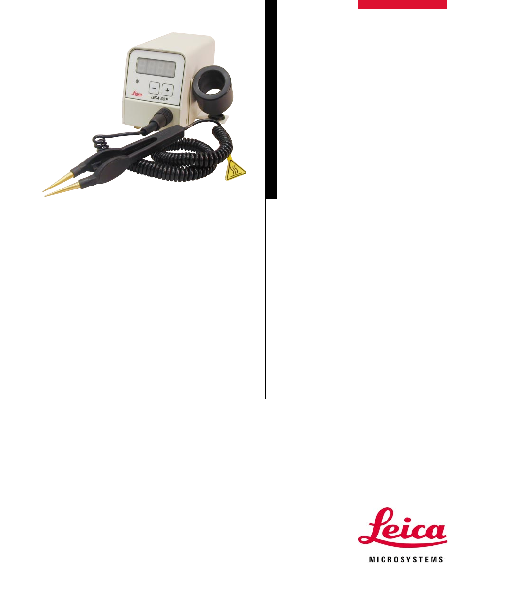
Leica EG F
Heatable forceps
Page 2

Page 3

NOTE
The information, numerical data, notes and value
judgments contained in this manual represent the
current state of scientific knowledge and stateof-the-art technology as we understand it following thorough investigation in this field. We are
under no obligation to update the present manual
periodically and on an ongoing basis according
to the latest technical developments, nor to provide our customers with additional copies, updates etc. of this manual.
For erroneous statements, drawings, technical
illustrations etc. contained in this manual we exclude liability as far as permissible according to
the national legal system applicable in each individual case. In particular, no liability whatsoever
is accepted for any financial loss or consequential damage caused by or related to compliance
with statements or other information in this
manual.
Statements, drawings, illustrations and other information as regards contents or technical details of
the present manual are not to be considered as
warranted characteristics of our products.
These are determined only by the contract provisions agreed between ourselves and our customers.
Leica reserves the right to change technical specifications as well as manufacturing processes without prior notice. Only in this way is it possible to
continuously improve the technology and manufacturing techniques used in our products.
This document is protected under copyright laws.
Any copyrights of this document are retained by
Leica Microsystems Nussloch GmbH.
Any reproduction of text and illustrations (or of
any parts thereof) by means of print, photocopy,
microfiche, web cam or other methods – including any electronic systems and media – requires
express prior permission in writing by Leica
Microsystems Nussloch GmbH.
For the instrument serial number and year of
manufacture, please refer to the name plate at
the back of the instrument.
© Leica Microsystems Nussloch GmbH
Issued by:
Leica Microsystems Nussloch GmbH
Heidelberger Str. 17-19
D-69226 Nussloch
Germany
Phone: + 49 6224 143-0
Fax: + 49 6224 143-200
e-mail: histo_info@leica-microsystems.com
Internet: http://www.histo-solutions.com
Leica EG F
3
Page 4

Table of contents
1. Important notes ...............................................................................................................5
1.1 Symbols in this manual and their meaning .................................................................. 5
1.2 Specified use and application ....................................................................................... 5
2. Safety ................................................................................................................................. 6
2.1 Safety regulations ............................................................................................................ 6
2.2 Safety instructions ........................................................................................................... 7
3. Installation ....................................................................................................................... 8
3.1 Scope of delivery ............................................................................................................. 8
3.2 Setting up the instrument ............................................................................................... 8
3.3 Electrical connection ...................................................................................................... 9
4. Instrument features ...................................................................................................... 11
4.1 Overview – Components / functions........................................................................... 11
4.2 Instrument parts/functions ........................................................................................... 12
4.3 Technical data ................................................................................................................ 13
5. Warranty and service................................................................................................... 14
4
Instruction Manual V1.0 – 03/2003
Page 5
1. Important notes
1.1 Symbols in this manual and their meaning
Dangers, warnings and cautions
appear in a gray box and are
marked by a warning triangle
Notes,
i.e. important information for the
user, appear in a gray box and are
(5)
(Fig. 5)
marked with
Figures in brackets refer to item
nos. in drawings or to the drawings
themselves.
Instrument surfaces which become
hot during operation are marked
with this symbol
.
1.2 Designated use
The Leica EGF are electrically heated forceps
that are used to transfer and orient histologic
tissue samples.
.
Any use of the instrument other than its designated use is considered improper.
If additional requirements on accident prevention and environmental
proctection exist in the country of
operation, this instruction manual
must be supplemented by appropriate instructions to ensure compliance with such requirements.
Leica EG F
Instrument type:
All information contained in this instruction manual applies solely
to the instrument type indicated on the cover page.
Required information for all enquiries
For any enquiries please be sure to specify:
• Instrument type
• Serial number
A name plate with the instrument serial number is attached to the
bottom of the instrument.
5
Page 6

2. Safety
Be sure to comply with the safety instructions and warnings in this chapter.
Be sure to read these instructions, even if you are already familiar with the operation and
use of other Leica products.
2.1 Safety instructions
This instruction manual contains important instructions and information
regarding the operational safety and maintenance of the instrument.
The instruction manual is an important part of the product, which must
be read carefully prior to setup and use and must always be kept near
the instrument.
This instrument was built and tested in accordance with the safety regulations for electrical measuring, control, regulating and laboratory devices as
specified below:
• EN 61010 -1 • EN 61000 -3-2
• EN 61010 -2 • EN 61000 -3-3
• EN 61326-1.
In order to maintain this condition and ensure safe operation, the operator
must observe all the instructions and warnings contained in this instruction
manual.
6
Instruction Manual V1.0 – 03/2003
Page 7

2.2 Warnings
The instrument must be connected to mains only with one of the supplied power cords and
only to grounded sockets. The protective function must not be removed through the use of
an extension cord without protective earth conductor.
Extreme temperature fluctuations between storage facility and setup site as well as high
humidity may cause condensation to form. In this case, a two-hour waiting period must be
maintained before switching on the instrument. Failure to observe the waiting period may
result in damage to the instrument.
The instrument may only be operated by trained laboratory personnel.
It may only be used according to its designated use and the instructions in this instruction
manual.
The instrument may be opened for maintenance or repair work by authorized service
technicians only.
2. Safety
To ensure perfect operation of the instrument, the following safety instructions and warnings must be observed:
Leica EG F
Switch the instrument off and unplug it before each cleaning.
Do not use any solvent containing acetone or xylene for cleaning.
While handling cleaning materials, observe the safety regulations of the manufacturer
and the applicable laboratory regulations.
The instrument must not be operated in hazardous locations.
Before replacing the fuses, switch the instrument off and pull the power plug from the
wall socket.
Do not use any fuses other than factory-installed fuses.
For corresponding fuse specifications see Chapter 4.3 “Technical Data.“
7
Page 8

3. Installation
3.1 Scope of delivery
The Leica EG F standard delivery consists of:
• control unit
• heatable forceps, tip width 1 mm
• forceps holder with paraffin collecting tray
• 1 set of power cords (see p. 9)
• 1 set of fuses
• instruction manual.
Carefully check the delivery against the packing list, delivery
note and your order.
Should there be any discrepancy, please contact the Leica
sales unit handling your order or your Leica dealer.
3.2 Setting up the instrument
• Carefully remove the control unit from its packaging.
• Unpack the forceps.
• From the supplied set of power cords, select the correct one for your
locale.
• Remove forceps holder with paraffin collecting tray from the packaging.
Necessary assembly work
Proceed as follows to make the instrument
ready for use:
• Forceps holder (1) with paraffin collecting
tray (2) is factory-installed on the right side.
If it needs to be installed on the left hand side,
follow these steps:
- Loosen the four Phillips screws (3) on the
bottom of the instrument.
- Remove forceps holder / collecting tray,
reverse it and fasten it to the opposite side
(insert screws in corresponding holes on
oppposite side).
8
1
3
2
Fig. 3
Instruction Manual V1.0 – 03/2003
Page 9

3.3 Electrical connection
The Leica EG F can be connected to different electrical supply systems
(voltage and frequency-dependent, see Chapter “Technical Data“).
For this reason, the instrument is supplied with a set of different power
cords containing an appropriate cord for each of the following geographical locations:
Location:
Australia Italy
Switzerland Great Britain
Europe USA, Canada, Japan
Please observe the following notes to prevent damage to the instrument:
3. Installation
The instrument MUST be connected to a grounded mains
socket.
Only the power cord intended for the local power supply
(socket) may be used.
Do not use an extension cord!
Leica EG F
The instrument can be connected to the following voltages:
100 to 127 V, 50/60 Hz or 200 to 240 V, 50/60 Hz.
The instrument is set to 220 to 240 V, 50/60 Hz at the factory (Fig. 4). If the
voltage needs to be changed, insert a screwdriver in the slot (3) and
change the setting to the desired value.
3
Fig. 4
9
Page 10

3. Installation
6
Replacing fuses
Connecting to mains
Before connecting the instrument to
the mains, ensure that the voltage
1
5
7
8
selector switch is set to the correct
local voltage!
An incorrect setting of the voltage
selector can cause serious damages to the instrument!
The instrument must be disconnected from mains before changing
the voltage selection.
Connecting the power cord
• Before connecting the power cord, ensure
that the mains switch (1) is set to off = 0.
Fig. 5
• Select the power cord with the correct connector for your mains power socket from
the supplied set of power cords.
Switch the instrument off and unplug it. Use only the supplied replacement fuses.
• Insert a small screwdriver into the cutout (5)
and carefully pry out the insert.
• Remove the fuse housing (8) together with
the fuses (7).
• Replace the defective fuses, reinsert the
fuse housing in the instrument and press
down until it snaps into place (audible click).
10
The instrument must be connected to
mains only with the supplied power
cord and only to a grounded socket.
• Connect the plug of the power cord to the
connecting socket (6) on the rear of the control unit.
• Plug the power cord into the mains power
socket.
Instruction Manual V1.0 – 03/2003
Page 11

4.1 Overview – Components / functions
4. Instrument features
Control instrument (front view)
Heatable forceps
(tip width 1 mm),
with cable
Fig. 6
Control panel
Voltage selector
Forceps holder
Paraffin collecting tray
Control unit (rear view)
Mains switch
Fig. 7
Leica EG F
Connecting socket for power cord
11
Page 12

4. Instrument features
4.2 Instrument parts / functions
The control panel on the front side of the control unit consists of a membrane keypad with push buttons (2), a single-line display (1) and an LED
1
(3) which flashes yellow during the warm-up phase. If the preselected
operating temperature is reached, this indicator lights permanently,
3
Temperature display
2
thereby signaling its readiness.
Two options are available for selecting the temperature display:
• Temperature in °C
• Temperature in °F
Changing the temperature unit
12
• Switch off mains switch of the control unit.
• Switch on the control unit back on, while holding the keys
pressed.
Changing the temperature
• Change the temperature value by pressing the or key.
Important!
The forceps holder will become hot. Risk of burning yourself!
Instruction Manual V1.0 – 03/2003
Page 13

4.3 Technical data General data
Approvals: The approval symbols relating to this instrument are
Nominal supply voltage: 100-127 V, 50/ 60 Hz
Power draw: 8 VA
Protective class
Pollution degree1:2
Overvoltage category: II
Operating temperature range: +18 °C to + 40 °C
Working temperatures: 55 °C to 70 °C
Relative air humidity: maximum 60 %, non-condensing.
1)
according to IEC-1010, UL 3101, EN 61010
Fuses
Fine-wire fuses 5 x 20 mm: T 1.25 A
Type of fuse: Wickmann: type 195, Schurter: type FST
Dimensions and weight
Dimensions:
Height: 110 mm
Width: 130 mm
Depth: 180 mm
Weight: approx. 1.5 kg
located on the instrument side next to the nameplate.
220-240 V, 50/ 60 Hz
1
:I
4. Instrument features
Programmable parameters
Temperature ranges displayed in °C or °F
Leica EG F
13
Page 14

5. Warranty and service
Warranty
Leica Microsystems Nussloch GmbH guarantees that the contractual
product delivered has been subjected to a comprehensive quality control
procedure based on the Leica in-house testing standards, and that the
product is faultless and complies with all technical specifications and/
or characteristics warranted.
The scope of warranty depends on the contents of the individual
contract concluded, being regarded as binding only the warranty
conditions of your local Leica sales unit or of the company from which
you acquired the product.
Technical service information
If you require technical service or replacement parts, please contact
your Leica sales office or dealer who sold the product.
Please provide the following information:
• Model name and serial number of the instrument.
• Location of the instrument and name of the person to contact.
• Reason for the service call.
• Date of delivery.
Decommissioning and disposal
The instrument or parts of the instrument must be disposed of in compliance with the local laws.
14
Instruction Manual V1.0 – 03/2003
Page 15

Notes
Leica EG F
15
Page 16

Notes
16
Instruction Manual V1.0 – 03/2003
 Loading...