

Leica EG 1150 H V2.2 User Manual
Instruction Manual
Leica EG1150H
V2.2 English, Rev. B - 12/2009
Always keep this manual near the instrument.
Read carefully prior to operating the instrument.
Leica EG1150 H
Paraffin Embedding
Station


IMPORTANT NOTE
The information, numerical data, notes and value judgments contained in this manual represent the current state of scientific knowledge
and state-of-the-art technology as we understand it following thorough investigation in this
field.
We are under no obligation to update the
present manual periodically and on an ongoing
basis according to the latest technical developments, nor to provide our customers with additional copies, updates etc. of this manual.
For erroneous statements, drawings, technical
illustrations, etc. contained in this manual we
exclude liability as far as permissible according
to the national legal system applicable in each
individual case. In particular, no liability whatsoever is accepted for any financial loss or consequential damage caused by or related to
compliance
in this manual.
Statements, drawings, illustrations and other
information as regards contents or technical
details of the present manual are not to be considered as warranted characteristics of our
products.
with statements or other information
These are determined only by the contract provisions agreed between ourselves and our customers.
Leica reserves the right to change technical
specifications as well as manufacturing processes without prior notice. Only in this way is it
possible to continuously improve the technology and manufacturing techniques used in our
products.
This document is protected under copyright
laws. Any copyrights of this document are
retained by Leica Biosystems Nussloch GmbH.
Any reproduction of text and illustrations (or of
any parts thereof) by means of print, photocopy,
microfiche, web cam or other methods — including any electronic systems and media — requires express prior permission in writing by
Leica Biosystems Nussloch GmbH.
For the instrument serial number and year of
manufacture, please refer to the name plate at
the left side of the instrument.
© Leica Biosystems Nussloch GmbH
Published by:
Leica Biosystems Nussloch GmbH
Heidelberger Str. 17 - 19
D-69226 Nussloch
Germany
Phone: +49 (0)6224 143-0
Fax: +49 (0)6224 143-268
Internet: http://www.leica-microsystems.com
Leica EG1150H – Paraffin Embedding Station
3

Table of contents
1. Important notes .......................................................................................................................................................... 5
1.1 Symbols used in the text and their
meanings .....................................................................................................................................................................5
1.2 Specified use and application ................................................................................................................................. 5
1.3 User group ................................................................................................................................................................... 5
1.4 Instrument type ........................................................................................................................................................... 5
2. Safety .......................................................................................................................................................................... 6
2.1 Safety regulations ...................................................................................................................................................... 6
2.2 Safety instructions ..................................................................................................................................................... 6
2.3 Built-in safety devices ............................................................................................................................................... 8
3. Instrument components and specifications ......................................................................................................... 9
3.1 Specifications ............................................................................................................................................................. 9
3.2 Overview – instrument parts .................................................................................................................................. 10
3.3 Instrument specifications ....................................................................................................................................... 11
4. Commissioning ......................................................................................................................................................... 12
4.1 Unpacking and installation ..................................................................................................................................... 12
4.3 Package contents .................................................................................................................................................... 13
4.2 Location conditions.................................................................................................................................................. 13
4.4 Necessary assembly work ..................................................................................................................................... 14
4.5 Optional accessories ...............................................................................................................................................16
4.6 Electrical connection ..............................................................................................................................................17
5. Operation ...................................................................................................................................................................18
5.1 Instrument parts/functions ..................................................................................................................................... 18
5.2 Switching the instrument on .................................................................................................................................. 23
5.3 Control panel functions ........................................................................................................................................... 24
5.4 Operating modes ...................................................................................................................................................... 25
5.5 Time-program control ............................................................................................................................................. 26
5.6 Instrument heater ..................................................................................................................................................... 28
6. Cleaning and maintenance ....................................................................................................................................30
6.1 Cleaning the instrument .......................................................................................................................................... 30
6.2 Maintenance instructions ......................................................................................................................................31
7. Troubleshooting ....................................................................................................................................................... 32
7.1 Possible faults ...........................................................................................................................................................32
7.2 Replacing the halogen lamp ................................................................................................................................... 35
7.3 Changing a fuse ........................................................................................................................................................36
8. Warranty and service .............................................................................................................................................38
4
Instruction Manual V 2.2, Rev. B – 12/2009
1. Important notes
1.1 Symbols used in the text and their
meanings
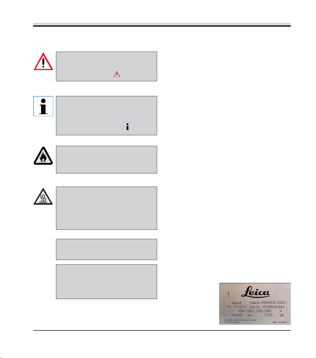
Warnings and cautions
appear in a gray box and are marked
by a warning triangle
Notes,
i.e. important information for the
user, appear in a gray box and are
marked with the symbol
Solvents and reagents that are inflammable are marked with this
symbol.
This warning symbol indicates the
surfaces on the instrument that are
hot during operation.
Avoid direct contact to prevent risk
of burning.
.
.
1.2 Specified use and application
The Leica EG1150H is a modern paraffin embedding station with microprocessor control.
It is designed for embedding histological tissue
specimens in molten paraffin for use in pathology laboratories and only for the following tasks:
• Melt solid paraffin for sample embedding
and maintain the molten paraffin at the required temperature.
• Fill the molds, in which the tissue specimens
were placed, with paraffin.
• Heat and maintain the temperatures of embedding cassettes with specimens and
molds as well as the required forceps.
Any other use of the instrument will be
considered as improper use!
1.3 User group
• The Leica EG1150H may only be operated by
qualified personnel.
• The user must read the operating instructions supplied and be familiar with all the instrument’s technical details before any work
on the instrument can be carried out.
(5)
ENTER
Leica EG1150H – Paraffin Embedding Station
Figures in brackets refer to item
numbers in figures.
Function keys that have to be
pressed on the input screen, are displayed in bold type and capital letters.
1.4 Instrument type
All information in this instruction manual applies
only to the instrument type indicated on the title
page.
A name plate with
the serial number
is attached to the
back of the instrument.
5
2. Safety
Be sure to comply with the safety instructions and warnings provided in this chapter.
Be sure to read these instructions, even if you are already familiar with the operation and
use of other Leica products.
2.1 Safety notes
This instruction manual contains important
instructions and information regarding the
operational safety and maintenance of the
instrument.
The instruction manual is an important part of
the product, which must be read carefully prior
to start-up and use and must always be kept
near the instrument.
If additional requirements on accident
prevention and environmental protection exist in the country of operation,
this instruction manual must be
supplemented by appropriate instructions to ensure compliance with such
requirements.
The protective devices on both instrument and accessories may neither be removed nor modified. Only service personnel qualified by Leica may repair the instrument and access the
instrument’s internal components.
This instrument has been built and tested in accordance with the safety regulations for electrical measuring, control, regulating and laboratory devices.
To maintain this condition and ensure safe operation, the user must observe all notes and
warnings contained in this Operating Manual.
For current information about applicable standards, please refer to the
CE declaration for the instrument and
to our Internet site:
http://www.leica-microsystems.com
2.2 Warnings
The safety devices installed in this instrument by the manufacturer only constitute the basis for
accident prevention. Primarily responsible for accident-free operation is above all the owner
of the instrument and, in addition, the designated personnel who operates, services or cleans
the instrument.
To ensure trouble-free operation of the instrument, make sure to comply with the following
instructions and warnings.
6
Instruction Manual V 2.2, Rev B – 12/2009
Safety instructions – safety regulations on the instrument itself
Safety regulations marked with a warning triangle on the instrument itself mean that
when operating or exchanging respective parts of the instrument, the correct operating
steps as described in the instruction manual supplied, must be adhered to. Non-observance can cause accidents, injuries and/or damage to the instrument/accessories.
Certain surfaces of the instrument are hot during operation under normal
conditions. They are marked with this warning sign. Touching these surfaces
can cause burns.
Safety instructions – transport and installation
After unpacking the instrument it may only be transported in an upright position.
Place the instrument on a laboratory table and adjust it to a horizontal position.
The instrument must not be exposed to direct sunlight (window)!
Plug the instrument only into a grounded mains socket. The protective effect may not be
eliminated by an extension cable without a protective grounding conductor.
The instrument automatically recognizes the applied voltage/frequency.
The installation location must be well-ventilated; there should be no ignition sources
there of any kind.
The instrument may not be operated in hazardous locations.
Extreme temperature fluctuations between storage facility and setup site as well as high
humidity may cause condensation to form. In this case, wait at least two hours before
switching on.
2. Safety
Safety instructions – working with the instrument
Paraffin is flammable and should therefore be handled with due care. Do not use sharp
tools to remove solidified paraffin from the work areas, as this may destroy the coating on
the surface. Use the plastic spatula supplied with the instrument.
During operation, the paraffin reservoir, mold warmer, cassette warmer, work area as
well as the forceps holder are hot.
Risk of burning!
Do not store any combustible and flammable substances near the instrument. There is a
fire hazard if work with an exposed flame (e.g. Bunsen burner) is carried out in the direct
vicinity of the instrument (solvent vapors). Therefore a minimum safety distance of 2
meters must be adhered to!
Leica EG1150 H – Paraffin Embedding Station
7
2. Safety
Hazards – servicing and cleaning
Switch off the instrument each time before servicing and pull out the mains plug.
When using cleaners, please comply with the safety instructions of the manufacturer and
the laboratory safety regulations.
Before changing defective fuses, the instrument has to be disconnected from the mains.
Only fuses that are easily accessible may be replaced by the user.
Set the standby switch to “Standby“ (
power cable out of the mains socket.
During operation and cleaning, do not allow any liquid to penetrate inside the instrument
and the transporting arm.
2.3 Built-in safety devices
The instrument is equipped with the following safety features and devices:
Fuses in the heating elements
All resistance mats of the instrument are equipped with overheating fuses,
which switch the heating element off if overheated.
) when replacing the halogen lamp and pull the
Automatic circuit breaker in standby switch
An automatic circuit breaker is located in the standby switch. This circuit
breaker separates the power electronics from the mains power supply in
the event of a short-circuit.
In this case, the standby switch jumps to the position “0“ = Off.
Note that the only way the user has for complete disconnection from the mains supply is
disconnection of the mains plug.
8
Instruction Manual V 2.2, Rev. B – 12/2009

3.1 Specifications
General data
Approvals: The approval symbols relating to this instrument are located
Power voltages: 100-120 V, 50/ 60 Hz
Input: 1100 VA
Class of protection
Degree of pollution1:2
Overvoltage category: II
Operating temperature range: +18 °C to + 40°C
Working temperatures: 55 °C to 70 °C, adjustable in 5 degree (K) increments.
Relative air humidity: maximum 60 %, non-condensing.
1)
according to IEC-1010, UL 3101, EN 61010
Fuses
Standby switch: Circuit breaker manufactured by ETA,
Fine-wire fuses 6.3 x 32 mm: 2x T 2.0 A; 2x T 3.2 A; T2x 4.0 A; T2x 5.0 A; T2x 6.25 A
Fuse type: Co. Schurter: type Fst
3. Instrument components and specifications
on the rear of the instrument next to the nameplate.
230-240 V, 50/ 60 Hz
1
:I
model 3120-F421-P7T1-W01D-5A
Dimensions and weight
Dimensions:
Height: 360 mm
Width: 500 mm
Depth: 640 mm
Weight: approx. 22 kg
Capacities
Paraffin reservoir: approx. 3 l
Cassette warmer: approx. 100 cassettes
Mold warmer: approx. 50 molds
Programmable parameters
Temperature: Paraffin reservoir/dispenser
Time: Working days, current weekday
Leica EG1150 H – Paraffin Embedding Station
(heating-up time = 4h)
Mold warmer, cassette warmer, work area
Working times (start, end), time
9
3. Instrument components and specifications
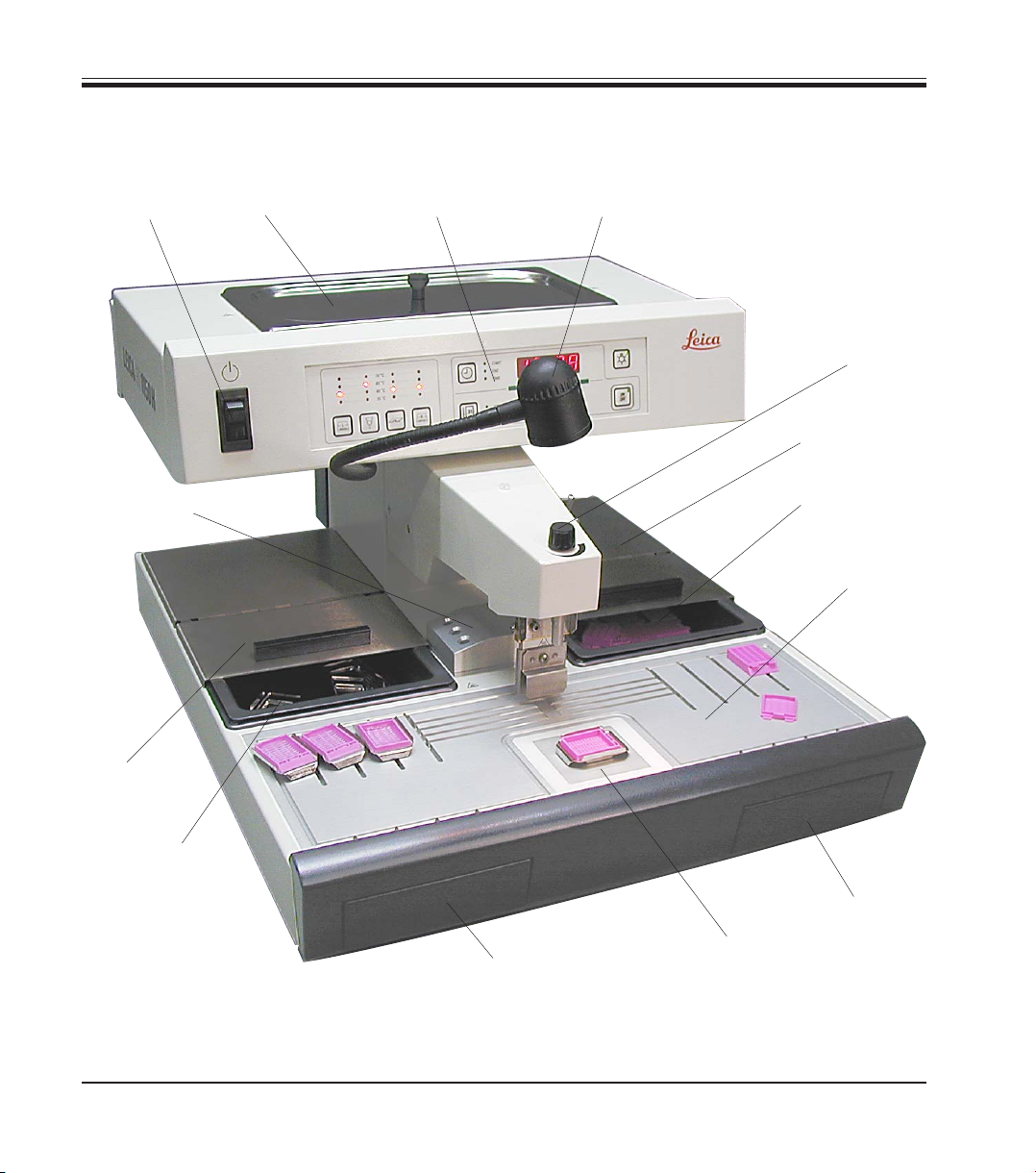
3.2 Overview – instrument parts
Standby
switch
Forceps holder
Paraffin reservoir
with lid
Control panel
Work area illumination
Dispenser
Cassette warmer
lid
Cassette warmer
Work area
Mold warmer
lid
Mold warmer
10
Paraffin collection tray
left
Instruction Manual V 2.2, Rev. B – 12/2009
Paraffin collection
tray right
Refrigeration spot
Fig. 1
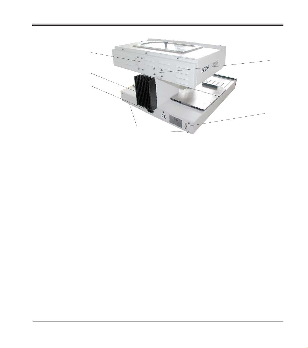
Instrument rear view
3. Instrument components and specifications
Secondary fuses F1-F3
Heat sink
Port for power cord
3.3 Instrument specifications
• Paraffin reservoir with a capacity of 3 liters.
• The paraffin flow is activated by means of a height-adjustable,
pivotable clip – activated either manually by the mold or a foot switch
(optional).
• Controllable flow rate.
• Removable, heatable (indirectly, via the work surface) paraffin collection trays.
• Spacious, easy-to-clean, heated work area, with integrated refrigeration spot, also for extra large cassettes (‘Super Mega Cassettes’) with
paraffin flow system.
• Warmers for cassettes and/or molds with sliding lid, removable and interchangeable.
• Removable, heated forceps holder for 6 forceps, accessible from both
sides.
• Optimum illumination of the work surface by individually adjustable
halogen lamp.
• Temperature range of cassette and mold warmer, work area and paraffin reservoir adjustable from 55°C to 70°C.
• Permanent temperature display for all the work areas.
• The beginning and end of the work time and work days can be programmed.
Secondary fuses
F4-F5
Port for
foot switch
Sliding elements
Fig. 2
Leica EG1150 H – Paraffin Embedding Station
11
4. Commissioning
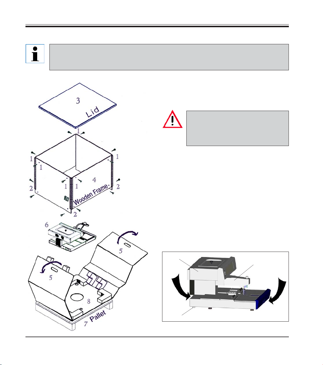
4.1 Unpacking and installation
The unpacking instructions are attached to the outside of the transport crate. Fig. 3
shows the design of the original packaging.
The numbers indicate the sequence of disassembling and reassembling.
• To lift up the instrument (6), hold it at the
front and rear of the base plate (Fig. 4) and
lift it from the foam padding (8).
Important!
Lifting the instrument by the dispenser (10) or paraffin reservoir (11)
can cause serious damage.
• After unpacking the instrument it should only
be transported in a horizontal position.
• Two slide faces (9) at the rear of the base
plate help to reposition the instrument on the
table. To reposition, slightly lift the instrument at the front of the base plate and slide
it on the slide faces.
• The instrument should be set up in such a
way that the air circulation is not affected. A
smooth operation is ensured only when the
instrument is set at a minimum distance of
15 cm from walls and furniture.
12
Fig. 3
11
10
9
Fig. 4
Instruction Manual V 2.2, Rev B – 12/2009
 Loading...