

Page 1

Leica AT930/AT960
Quick Guide
Version 1.2
English
Page 2
2
AT930/AT960, Important Information about your Instrument
1 Important Information about your Instrument
Read and follow the User Manual on the accompanying USB documentation card
before using the product or the accessories delivered with the product.
Keep for future reference!
Intended use • Measuring coordinates.
• Recording measurements.
• Computing with software.
• Automatic target search, recognition and following.
• Remote control of product.
• Data communication with external appliances.
Laser products The AT930/AT960 instrument contains the following laser products:
Laser product Laser class Classification
ADM (Absolute Distance Meter) Class 1 IEC 60825-1 (2014-05)
Laser Interferometer Class 1 IEC 60825-1 (2014-05)
PowerLock Exempt Group IEC 62471 (2006-07)
LED status indicator Exempt Group IEC 62471 (2006-07)
Page 3

AT930/AT960, Important Information about your Instrument 3
Locations of laser
apertures
CAUTION
From a safety perspective, class 2 laser products are not inherently safe for the eyes.
Precautions:
1) Avoid staring into the beam or viewing it through optical instruments.
2) Avoid pointing the beam at other people or at animals.
The AT930/AT960 is classified as a laser class 2 system although the individual laser
sources are classified as laser class 1. The possibility of simultaneous emission of the
individual laser sources results in an overall classification as laser class 2.
a) LED Status Indicators
b) PowerLock
c) ADM, Interferometer
008048_001
a
b
c
Page 4
4
AT930/AT960, Important Information about your Instrument
The following advice is only valid for the AC power supply.
WARNING
The product is not designed for use under wet and severe conditions. If unit becomes
wet it may cause you to receive an electric shock.
Precautions:
Use the product only in dry environments, for example in buildings or vehicles.
Protect the product against humidity. If the product becomes humid, it must not be
used!
The following advice is only valid for the AC power supply.
WARNING
If unit is not connected to ground, death or serious injury can occur.
Precautions:
To avoid electric shock power cable and power outlet must be grounded.
Page 5
AT930/AT960, Important Information about your Instrument 5
CAUTION
Risk of damage by overheating
If the product is covered by the protective cover while being switched on, the product
may be damaged by overheating.
Precautions:
• Ensure that the product is switched off before covering it with the protective
cover.
The product must not be disposed with household waste.
Conformity to
national
regulations
• FCC Part 15 (applicable in US)
• Hereby, Leica Geosystems AG, declares that the product is in compliance with the essential requirements and other relevant provisions of
the applicable European Directives. The declaration of conformity may
be consulted at http://www.leica-geosystems.com/ce.
Page 6

6
AT930/AT960, Important Information about your Instrument
Conformity to
national
regulations
• FCC Part 15 (applicable in US)
• Hereby, Leica Geosystems AG, declares that the product AT Controller with WLAN
module is in compliance with the essential requirements and other relevant
provisions of Directive 1999/5/EC and other applicable European Directives. The
declaration of conformity can be consulted at http://www.leicageosystems.com/ce.
Class 1 equipment according European Directive 1999/5/EC
(R&TTE) can be placed on the market and be put into service
without restrictions in any EEA Member state.
• The conformity for countries with other national regulations not covered by the
FCC part 15 or European directive 1999/5/EC has to be approved prior to use and
operation.
• Japanese Radio Law and Japanese Telecommunications Business Law Compliance.
– This device is granted pursuant to the Japanese Radio Law and the Japanese
Telecommunications Business Law.
– This device should not be modified (otherwise the granted designation
number will become invalid).
Page 7

AT930/AT960, Important Information about your Instrument 7
Dangerous Goods
Regulations
The products of Leica Geosystems are powered by Lithium batteries.
Lithium batteries can be dangerous under certain conditions and can pose a safety
hazard. In certain conditions, Lithium batteries can overheat and ignite.
When carrying or shipping your Leica product with Lithium batteries onboard
a commercial aircraft, you must do so in accordance with the
IATA Dangerous Goods Regulations.
Leica Geosystems has developed Guidelines on “How to carry Leica products” and “How to ship Leica products” with Lithium batteries. Before any
transportation of a Leica product, we ask you to consult these guidelines on
our web page (http://www.leica-geosystems.com/dgr) to ensure that you
are in accordance with the IATA Dangerous Goods Regulations and that the
Leica products can be transported correctly.
Damaged or defective batteries are prohibited from being carried or transported onboard any aircraft. Therefore, ensure that the condition of any
battery is safe for transportation.
Page 8
8
AT930/AT960, Container Contents
2 Container Contents
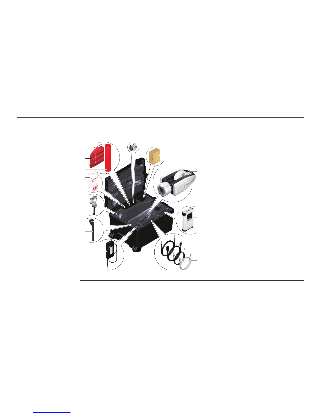
Container for
Instrument and
Delivered
Accessories
a) Optical cleaning kit
b) Protective cover for
AT930/AT960 instrument
c) Quick Guide and Product
Information USB Stick
d) Quick Release
e) Hinged Hook Wrench
f) AC Power supply
g) Universal Stand Fixture
h) Wooden box containing
1.5” Red Ring Reflector
i) AT930/AT960 instrument
j) AT Controller
k) Sensor cable
l) Power cable
m) External temperature sensor
n) Ethernet cable
008049_002
a
g
b
c
d
e
f
h
i
j
k
l
m
n
Page 9

AT930/AT960, Technical Data 9
3 Technical Data
Environmental
specifications
Temperature
Protection against water, dust and sand
IP54 (IEC 60529)
Humidity
Max 95 % non condensing.
To avoid the effects of condensation, periodically dry out the instrument.
4 Care and Transport
Care and transport • Carry the product in its original container or attached to the Tracker Stand, to
protect the product against shock and vibration.
• Periodically carry out test measurements and perform the field adjustments indicated in the User Manual, particularly after the product has been dropped, stored
for long periods or transported.
Type Operating temperature [°C] Storage temperature [°C]
AT930/AT960
instrument
+0 to +40 -25 to +70
AT Controller +0 to +40 -25 to +70
Page 10
10
AT930/AT960, Operation
5 Operation
System
Components
Component Description
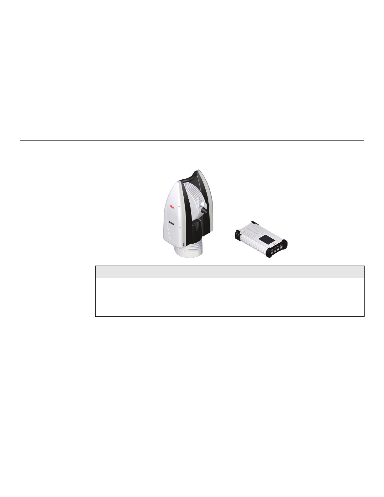
AT930/AT960
instrument
Absolute Tracker of highest accuracy for measuring, calculating
and capturing data.
AT930: 3D Measurements
AT960: 3D & 6DoF Measurements
008050_002
AT930/AT960
AT Controller
Page 11

AT930/AT960, Operation 11
AT Controller Controller running the system software which provides the inter-
face to the Absolute Tracker.
The optional Real-Time Feature Pack for Absolute Tracker
AT930/AT960 is designed to provide cyclic measurement data in
real-time over an industrial field bus protocol, for example
EtherCAT, with minimum jitter and small latency.
Application
Software
Third-party metrology software with an interface to the Absolute Tracker for acquisition, analysis, management, automation
and reporting of measurement data.
Tracker Pilot System software to
• check the system accuracy and adjust (compensate) instrument parameters.
• maintain and update the system software/firmware.
Component Description
Page 12
12
AT930/AT960, Setup
6Setup
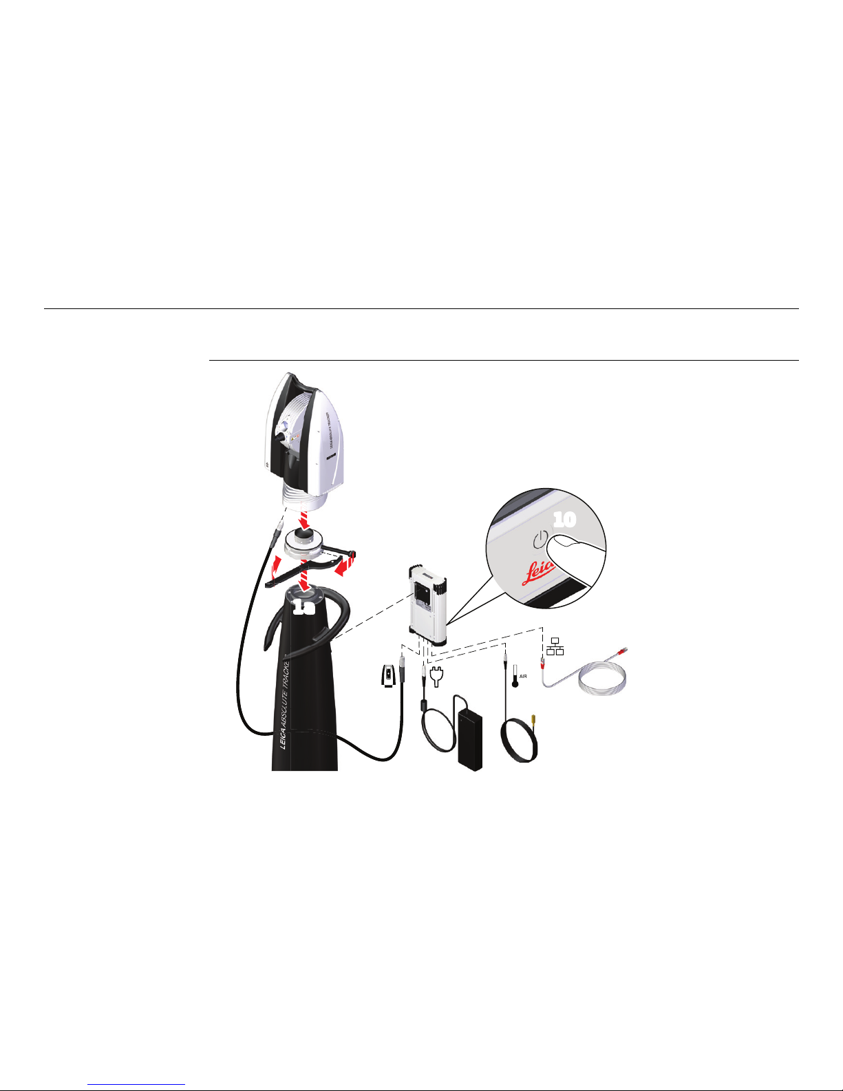
Setup Step-by-step
008051_002
1b
2
3
1a
4
59
6
7
8
10
Page 13

AT930/AT960, Setup 13
Step Description
1. Screw the Quick Release onto the Tracker Stand and tighten it using the
hinged hook wrench.
2.
Ensure that the locking lever of the Quick Release is in unlocked position.
Set the AT930/AT960 instrument onto the Quick Release.
3. Close the locking lever to lock the Absolute Tracker on the Quick Release.
Do not remove the locking lever of the Quick Release while the
sensor is attached to the Quick Release.
4. Attach the AT Controller to the Universal Stand Fixture.
This advice refers to the following instructions about connecting cables:
When plugging in cables, ensure that the controller is secured against slipping
out of the Universal Stand Fixture!
5. Connect the external temperature sensor to the port of the AT Controller,
that is labelled with “Air”. This ensures that you achieve the highest possible
measurement accuracy.
6. Connect one end of the sensor cable to the AT Controller.
7. Connect the other end of the sensor cable to the AT930/AT960 instrument.
8. Connect a LAN cable (if applicable).
Page 14
14
AT930/AT960, Setup
Refer to the relevant application manual for further details on carrying out
measurements.
WARNING
Mounting the sensor on unstable or uneven ground may cause the sensor to tip over
or cause unreliable measurement results.
Precautions:
Ensure the ground is stable and even. Do not place the sensor over cracks in the
floor.
9. Connect the AC power supply to the AT Controller and to a grounded mains
socket outlet.
10. To turn on the Absolute Tracker, press the power switch on the frontpanel
of the AT Controller.
11. The system automatically detects when the start-up cycle has finished. The
system will initialise automatically once the start-up cycle has finished.
12. Start the application.
Step Description
Page 15
AT930/AT960, Startup 15
7Startup
Startup 1) Set up the Absolute Tracker system according to "6 Setup".
2) Power up the system with the main power switch on the AT Controller.
3) Start the application software and connect to the Absolute Tracker.
4) Initialise the system.
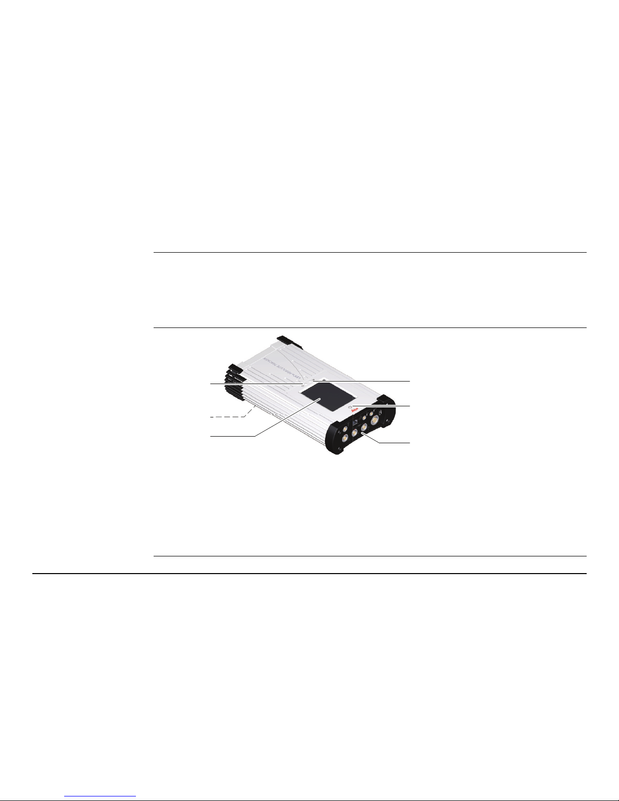
Controller Top View
a) Power status LED
b) Clip for Universal Stand Fixture (back side of the AT Controller)
c) Touch-sensitive status display with different information pages
d) WLAN status LED
e) Main power switch for AT Controller and AT930/AT960
f) Connectors
008052_002
a
b
c
d
e
f
Page 16

16
AT930/AT960, AT Controller Display
8 AT Controller Display
Description The AT Controller has a touch-sensitive VGA colour display. The display shows essen-
tial information about the Absolute Tracker system. The following pages are available:
• Startup splash screen
• Shutdown splash screen
• Software Update splash screen
•Main page
• Network Connection page
• Power Supply page
• Levelling page
• Meteo page
• Information page
• Information Details page
Display brightness The AT Controller boots with the pre-configured display brightness settings.
5 minutes after your last interaction on the AT Controller, the display dims back to
5% of the brightness range and changes to the main page.
To bring the display brightness back to the pre-configured level, touch the display
anywhere.
Page 17
AT930/AT960, AT Controller Display 17
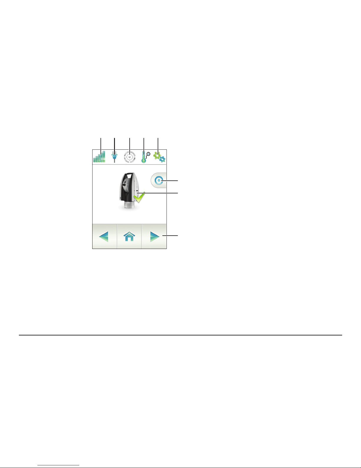
Main page
a) LMF connection status (includes WLAN
signal strength if connected by WLAN)
b) Power supply status
c) Levelling sensor status
d) Meteo data source
e) System information
f) Active measurement profile
g) Absolute Tracker status
h) Controller navigation controls
The icons change their appearance depending on the current status of the
feature that they represent.
ab cde
f
g
h
Page 18
18
AT930/AT960, AT Controller Display
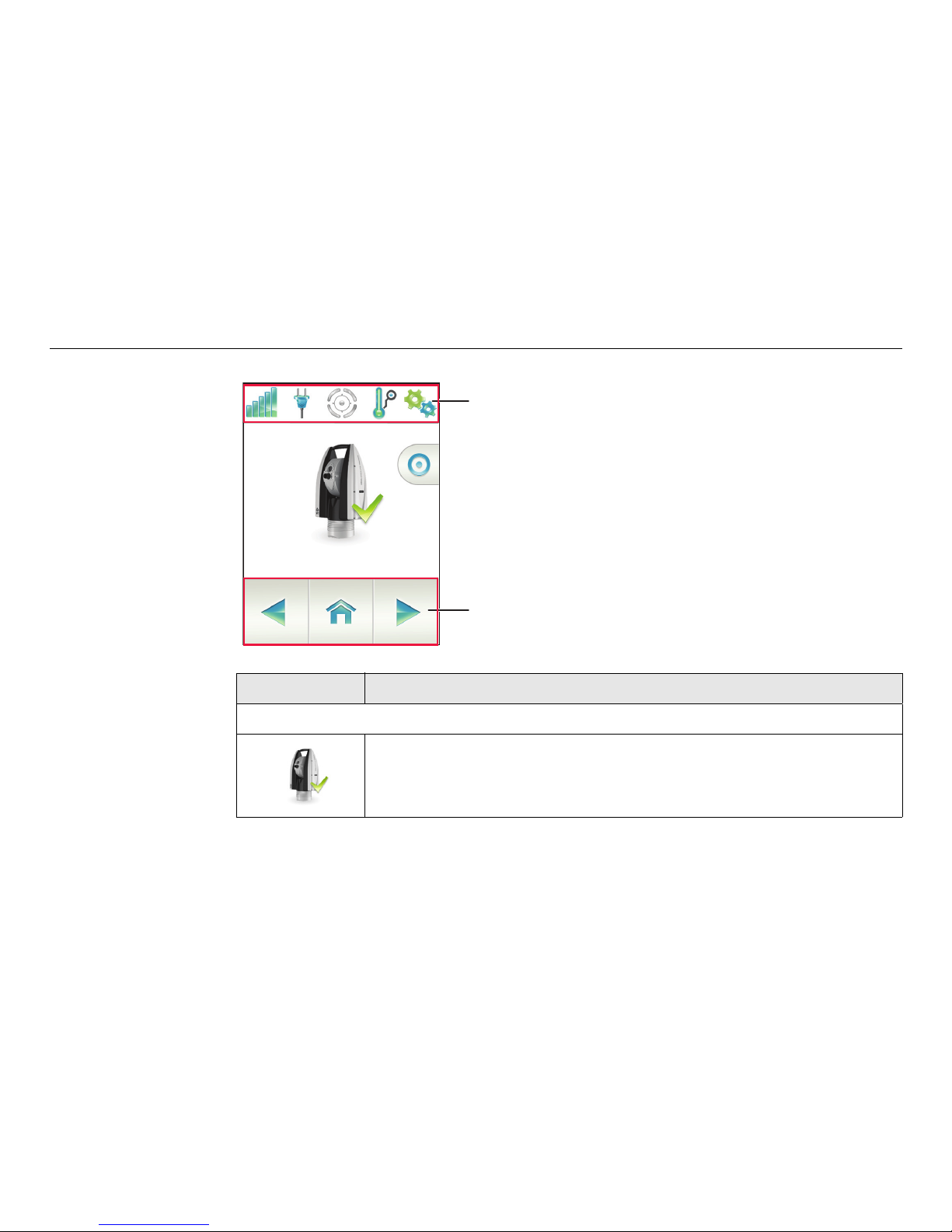
Touch screen sensitive areas:
a) Tap on an icon to display the corre-
sponding detail page.
b) Tap on the navigation control areas to
toggle between the detail pages and the
main page.
Status Icons Description
Absolute Tracker Status
System is ready.
a
b
Page 19
AT930/AT960, AT Controller Display 19
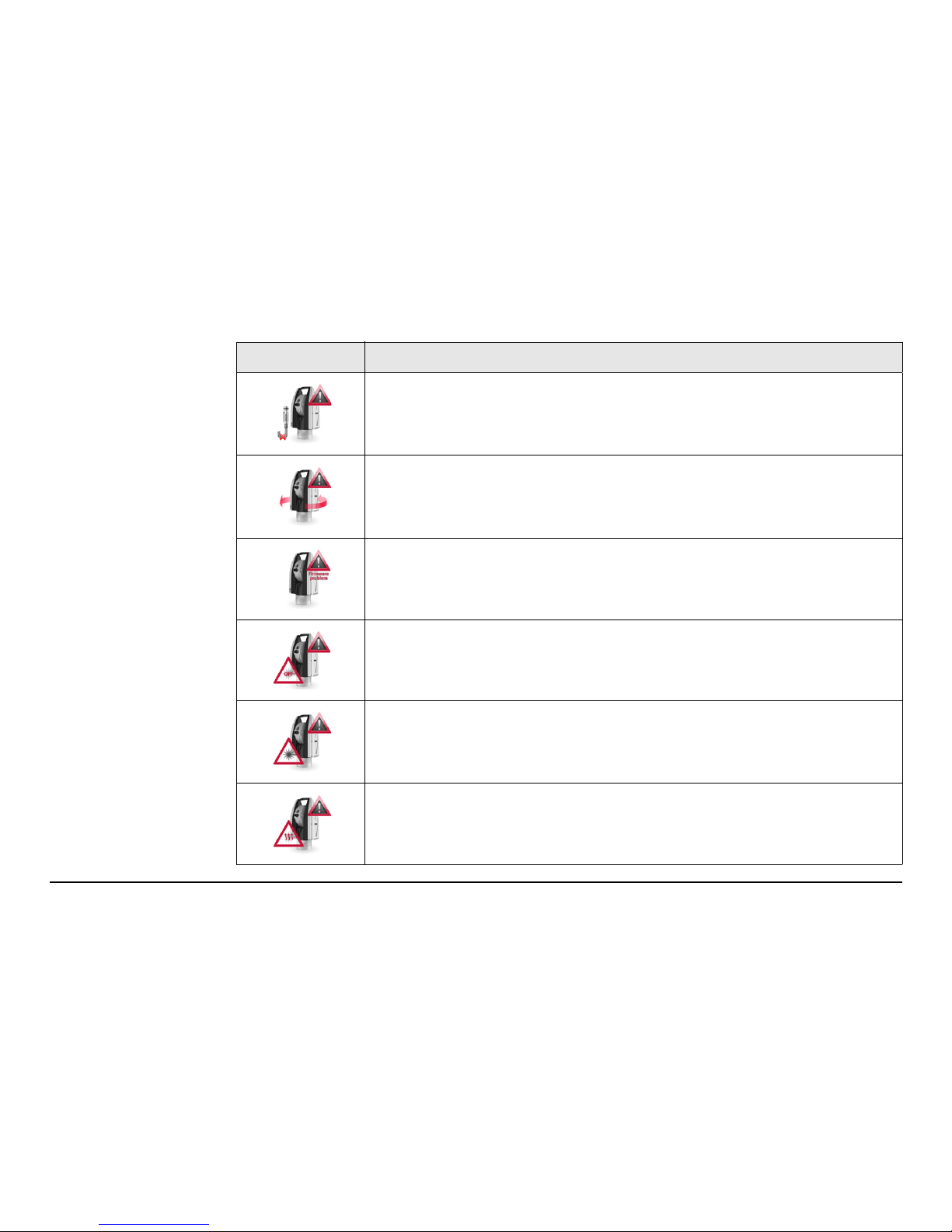
Sensor is not connected.
Tracker is not initialised.
Firmware problem. (Example: Not all device servers are available.)
Laser is off.
Laser is not ready.
Laser is warming up.
Status Icons Description
Page 20
20
AT930/AT960, AT Controller Display
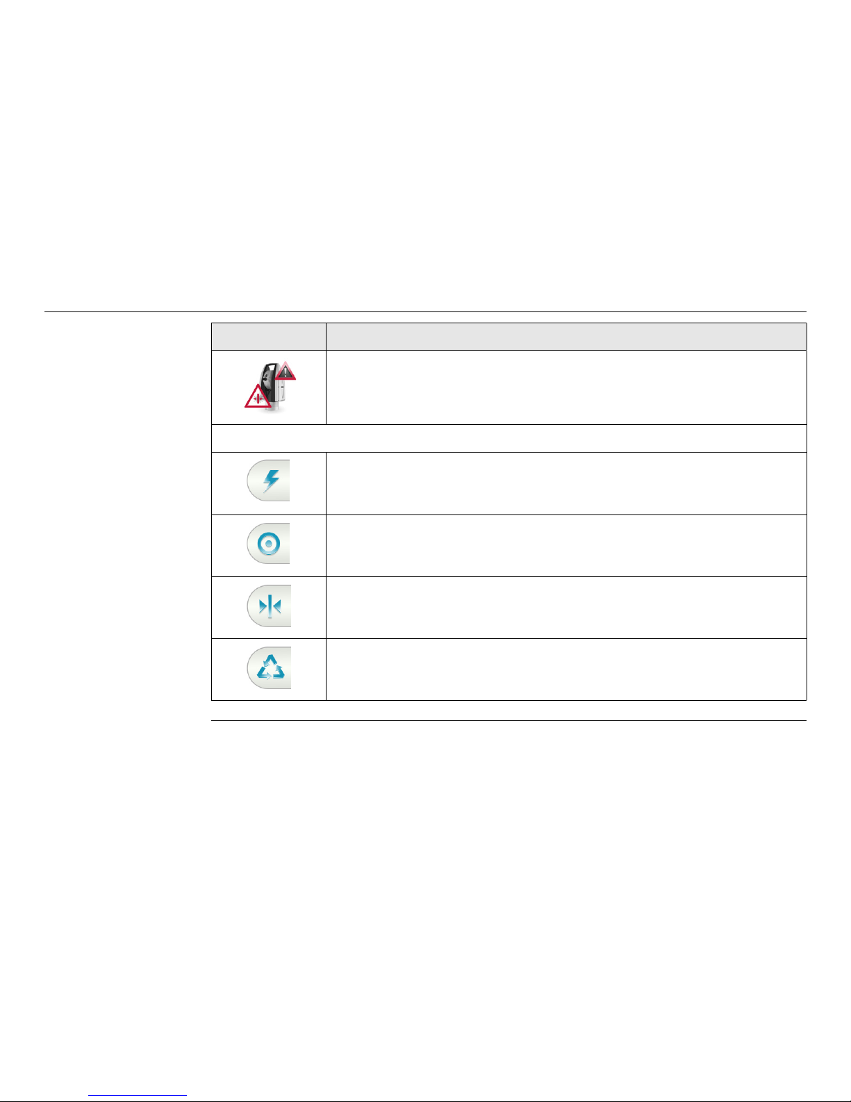
Laser is unable to stabilise.
Measurement Profiles
Fast
Standard
Precise
Continuous
Status Icons Description
Page 21
AT930/AT960, AT930/AT960 Instrument Status LEDs 21
9 AT930/AT960 Instrument Status LEDs
Status LEDs Description
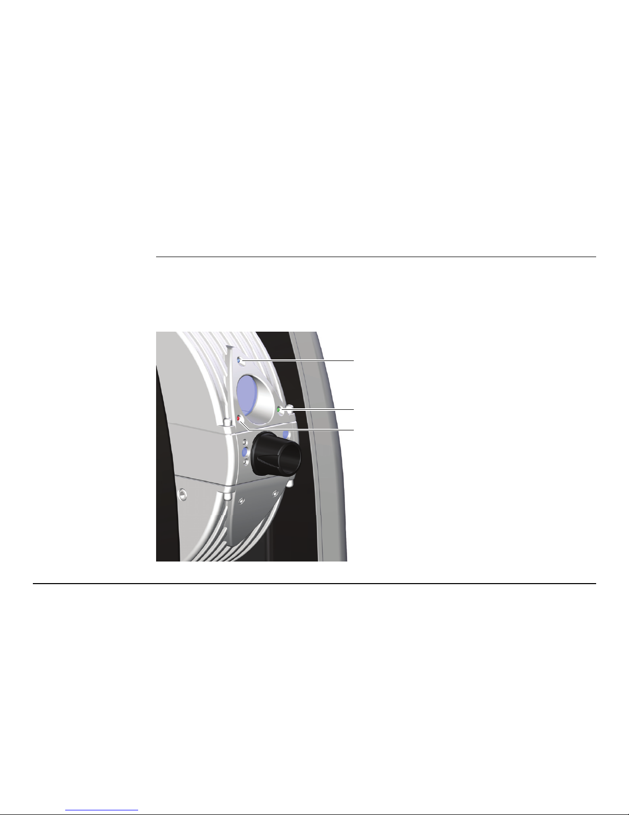
The AT930/AT960 has Light Emitting Diode indicators at the front side of the tele-
scope. They indicate the following states.
Diagram of the Status LEDs
a) Blue LED
b) Green LED
c) Red LED
a
b
c
Page 22

22
AT930/AT960, AT930/AT960 Instrument Status LEDs
Description of the Status LEDs
LED Pattern Status Information
Red, Green and Blue
LED
off The AT Controller or the AT930/AT960
instrument are off.
Red, Green and Blue
LED
static The system is booting up.
Red and Blue LED static The system is ready, no reflector is in the
field of view. PowerLock is activated.
Red LED static The system is ready, no reflector is in the
field of view. PowerLock is inactive.
Red LED flashing slowly Warm-up in progress. The system is not
ready to measure.
Red LED flashing shortly
interrupted by
longer breaks
Laser off (stand-by mode)
Red LED flashing Target is out of range (too close or too far).
Green LED static Target locked and stable. Ready to measure.
Green LED flashing Measurement is in progress.
Page 23

AT930/AT960, AT930/AT960 Instrument Status LEDs 23
Blue LED flashing slowly PowerLock is temporarily suspended while
laser is pointing.
LED Pattern Status Information
Page 24

24
AT930/AT960, EC Declaration of Conformity
10 EC Declaration of Conformity
EC Declaration of
Conformity
This corresponds to EN ISO/IEC 17050-1.
We, Leica Geosystems AG, CH-9435 Heerbrugg (Switzerland), declare under our
sole responsibility that the product(s) AT930, AT960-MR, AT960-LR, AT960-XR,
following the provision of Directive(s)
• 2011/65/EU Restriction of hazardous substances (RoHS)
• 2006/42/EC Machinery (MD)
• 2004/108/EC Electromagnetic compatibility (EMC)
to which this declaration relates, is in compliance with the following standards:
• EN ISO 12100:2010
• EN 60825-1:2014
• EN 61010-1:2010
• EN 61326-1:2013
Leica Geosystems AG
Page 25

AT930/AT960, EC Declaration of Conformity 25
For a signed version and translations into the official EU languages please
refer to: http://www.leica-geosystems.com/ce
Page 26

Leica Geosystems AG
Heinrich-Wild-Strasse
CH-9435 Heerbrugg
Switzerland
Phone +41 71 727 31 31
www.leica-geosystems.com
818742-1.2.0en
Original text
Printed in Switzerland
© 2015 Leica Geosystems AG, Heerbrugg, Switzerland
 Loading...