

Page 1
Operating Manual
Leica ASP200 S
V1.1 English - 03/2009
Always keep this manual together with the instrument.
Read this instruction manual carefully before working
with the instrument.
Leica ASP200 S
Advanced Smart Processor
Automated vacuum
tissue processor
Page 2

Page 3

NOTE
The information, numerical data, notes and value
judgments contained in this manual represent
the current state of scientific knowledge and
state-of-the-art technology as we understand it
following thorough investigation in this field.
We are under no obligation to update the present
manual according to the latest technical developments, nor to provide our customers with additional copies, updates etc. of this manual.
For erroneous statements, drawings, technical
illustrations etc. contained in this manual we
exclude liability as far as permissible according
to the national legal system applicable in each
individual case. In particular, no liability whatsoever is accepted for any financial loss or consequential damage caused by or related to compliance with statements or other information in this
manual.
Statements, drawings, illustrations and other
information as regards contents or technical
details of the present manual are not to be
considered as warranted characteristics of our
products.
These are determined only by the contract provisions agreed between ourselves and our customers.
Leica reserves the right to change technical
specifications as well as manufacturing processes without prior notice. Only in this way is it possible to continuously improve the technology and
manufacturing techniques used in our products.
This document is protected under copyright
laws. Any copyrights of this document are
retained by Leica Biosystems Nussloch GmbH.
Any reproduction of text and illustrations (or of
any parts thereof) by means of print, photocopy,
microfiche, web cam or other methods – including
any electronic systems and media – requires
express prior permission in writing by
Leica Biosystems Nussloch GmbH.
For the instrument serial number and year of
manufacture, please refer to the name plate at
the back of the instrument.
© Leica Biosystems Nussloch GmbH
Published by:
Leica Biosystems Nussloch GmbH
Heidelberger Str. 17 - 19
D-69226 Nussloch
Germany
Telephone: +49 (0)6224 143-0
Fax: +49 (0)6224 143-200
Internet: http://www.histo-solutions.de
Leica ASP200 S
3
Page 4

Table of Contents
1. Important information ................................................................................................................. 6
2. Safety ..............................................................................................................................................7
2.1 Safety instructions .................................................................................................................................... 7
2.2 Warnings .................................................................................................................................................... 7
2.3 Integrated safety devices ...................................................................................................................... 11
3. Instrument components and specifications ......................................................................... 12
3.1 Overview - instrument components..................................................................................................... 12
3.2 Specific instrument options .................................................................................................................. 14
3.3 Standard delivery - packing list ............................................................................................................ 15
3.4 Technical Data ........................................................................................................................................ 16
3.5 Compatible reagents .............................................................................................................................. 19
4. Setting up the instrument ......................................................................................................... 20
4.1 Site requirements ................................................................................................................................... 20
4.2 Electrical connection ............................................................................................................................. 20
4.3 Installing the accessories ..................................................................................................................... 21
4.4 Setting up the data connections .......................................................................................................... 23
4.5 Anti-reflection clip – Installation Instructions.................................................................................... 24
4.6 Alarm functions ....................................................................................................................................... 25
4.7 Switching the instrument on ................................................................................................................. 26
4.8 Touchscreen functions .......................................................................................................................... 28
4.9 Checklist for first operation ................................................................................................................... 29
4.10 Switching of the instrument .................................................................................................................. 30
5. Operation ..................................................................................................................................... 31
5.1 Setting up the instrument parameters ................................................................................................. 31
5.1.1 System setup ........................................................................................................................................... 31
5.1.2 Access levels .......................................................................................................................................... 34
5.1.2 INSTALLATION menu............................................................................................................................. 36
5.1.3 Editing the reagent list ........................................................................................................................... 39
5.1.4 Viewing the program list........................................................................................................................ 42
5.1.5 Adding and/or modifying programs ..................................................................................................... 43
5.1.6 Favorites ................................................................................................................................................... 46
5.1.7 Editing the stations ................................................................................................................................. 48
5.1.8 Reagent groups ....................................................................................................................................... 49
4
Operating Manual V 1.1 – 03/2009
Page 5

Table of Contents
5.2 Reagent handling .................................................................................................................................... 50
5.2.1 Fill/drain reagents (other than wax)..................................................................................................... 50
5.2.2 Changing the wax ................................................................................................................................... 52
5.3 Running programs .................................................................................................................................. 55
5.3.1 Editing a selected program ................................................................................................................... 56
5.3.2 Starting a program.................................................................................................................................. 58
5.4 Reagent status ........................................................................................................................................ 59
5.5 System Monitor ....................................................................................................................................... 60
5.6 On-line help.............................................................................................................................................. 61
6. Solutions...................................................................................................................................... 62
6.1 General ..................................................................................................................................................... 62
6.2 Power failure ........................................................................................................................................... 62
6.3 Troubleshooting ...................................................................................................................................... 63
6.4 Typical fill or drain problems................................................................................................................. 64
7. Cleaning and Maintenance ..................................................................................................... 65
7.1 Clean programs ....................................................................................................................................... 65
7.1.1 Retort clean programs ........................................................................................................................... 65
7.1.2 Wax clean program ................................................................................................................................ 67
7.1.3 Smart Clean ............................................................................................................................................. 68
7.2 General cleaning steps .......................................................................................................................... 69
7.3.1 Daily cleaning and maintenance.......................................................................................................... 71
7.3.2 Periodic cleaning and maintenance.................................................................................................... 73
7.4 Preventative maintenance schedule ................................................................................................... 74
8. Warranty and Service ............................................................................................................... 76
9. EC Declaration of Conformity ..................................................................................................77
Leica ASP200 S
5
Page 6
1. Important information
Symbols used in this manual
Warnings
appear in a gray box and are
(5)
ENTER
marked by a warning triangle
Notes,
i.e. important user information appear in a gray box and are marked
by an information symbol
Flammable solvents and reagents
are marked with this symbol.
Instrument surfaces which become
hot during operation are marked
with this symbol.
Avoid direct contact with these surfaces - they may cause burns.
Figures in brackets refer to item
nos. in drawings.
Function keys to be pressed on the
instrument touch screen are written
in bold-print capital letters.
.
.
Qualification of personnel
• The Leica ASP200 S may be operated only by
trained laboratory personnel.
•
The instrument may be operated only according to the instructions contained in this manual.
Designated use
The instrument has been designed so that it is
safe to use by the operator as well as for processing specimens – provided that it is operated
according to the present instruction manual.
The Leica ASP200S is a modular automated
tissue processor designed for the following laboratory applications:
• fixation,
• dehydration
• paraffin wax infiltration of histological
tissue specimens.
The Leica ASP200 S must be operated exclusively
with the reagents listed
in chapter 3.5 - "Compatible reagents" .
Any other use of the instrument is
considered improper!
Failure to adhere to these instructions may result in an accident,
personal injury, damage to the
instrument or accessory equipment.
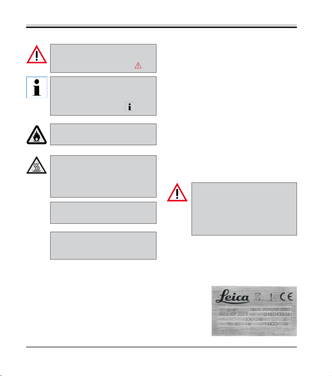
Instrument type
All information provided in this manual applies
only to the instrument type indicated on the title
page.
A name plate
indicating the
instrument
serial number
is attached to
the back of the
instrument.
Fig. 1
6
Operating Manual V 1.1 – 03/2009
Page 7
Make sure to comply with the safety instructions and warnings in this chapter.
Make sure to read these instructions, even if you are already familiar with the operation
and use of other Leica products.
2.1 Safety instructions
This instruction manual includes important information related to the operating safety and maintenance of the instrument and it is an important
part of the product.
2. Safety
This instrument has been built and tested in accordance with the safety regulations on electrical measuring, control, regulating and laboratory
devices.
In order to maintain this condition and to ensure
safe operation the operator must comply with the
instructions and warning contained in this
instruction manual.
If additional requirements on accident prevention and environmental
protection exist in the country of operation, this instruction manual
must be supplemented by appropriate instructions to ensure compliance with such requirements.
The protective devices on both instrument and accessories may neither be removed nor
modified. Only authorized and qualified service personnel may repair the instrument and
access the instrument’s internal components.
For current information on applicable
standards, please refer to the instrument’s CE declaration and visit:
http://www.histo-solutions.com
2.2 Warnings
The safety devices installed in this instrument by the manufacturer only constitute the basis for
accident prevention. Primarily responsible for accident-free operation is above all the institution
which owns the instrument and, in addition, the designated personnel who operates, services or
repairs the instrument.
To ensure trouble-free operation of the instrument, make sure to comply with the following
instructions and warnings.
Leica ASP200 S
7
Page 8
2. Safety
Warnings - Markings on the instrument itself
Markings on the instrument showing the warning triangle indicate that the correct
operating instructions (as defined in this manual) must be followed when operating or
replacing the item marked. Failure to adhere to these instructions may result in an accident, personal injury, damage to the instrument or accessory equipment.
Some instrument surfaces become hot during operation.
They are marked with this warning label. Touching these surfaces may cause
burns.
Transport and Installation
The instrument may only be transported in an upright position.
Follow the unpacking instructions carefully to avoid damage to the instrument!
A cleaning must be performed prior to each transport, during which the instrument may
be shaken, tilted or lifted. Severe internal damage may otherwise occur.
The instrument MUST be connected to an earthed mains power outlet socket. The instrument must not be connected to an extension cord without protective earth conductor.
Ensure uniform current supply according the to set voltage!
The set voltage CANNOT be changed by the user.
Severe damage may occur if the instrument is connected to a power supply voltage other
than that to which it was originally set.
The instrument must be set up in a well ventilated area, free from any ignition sources.
The chemicals to be used in the Leica ASP200 S are both flammable and noxious.
Do not operate the instrument in rooms with explosion hazard.
If there is a significant difference in temperature between the warehousing and the installation site of the instrument and if at the same time there is a high air humidity level,
condensation water may form. In this case, a waiting period of at least two hours must be
observed before the instrument is switched on. Failure to adhere to this waiting period
may result in damage to the instrument. Failure to adhere to this waiting period may result in damage to the instrument.
8
Operating Manual V 1.1 – 03/2009
Page 9
Warnings - Operating the instrument
The Leica ASP200S may only be operated by trained laboratory personnel, according to
its designated use and per the present instruction manual.
The ON/STOP switch at the side of the instrument may be used in an emergency to stop
the instrument during operation.
Always press PAUSE before opening the retort lid during processing to allow the retort to
vent.
Do not remove the wax drain hose or the remote fill/drain hose until the fill or drain has
been completed, as pressurized air is used to clear the hose after each fill / drain.
After refilling / replacing the reagent bottles ensure that the lids are tight.
The bottles must be properly pushed home into the connection manifolds at the rear inner
wall of the reagent module.
Failure to correctly plug the reagent bottles into the manifold will cause an interruption
to the processing run and may result in spilling of reagents.
Fixatives containing mercuric salts, acetic or picric acid will corrode metallic components in the instrument.
2. Safety
After each paraffin step a retort clean cycle must be run.
Material safety data sheets can be obtained from the supplier of the chemicals.
They are also available on the Internet:
http://www.msdsonline.com
Leica ASP200 S
9
Page 10
2. Safety
Warnings -handling reagents
Be careful when handling solvents!
Always wear rubber gloves and safety goggles when handling the chemicals used in this
instrument.
Reagents used for tissue infiltration can be both toxic and/or flammable.
To avoid damaging the instrument only use those reagents that are listed in chapter 3.5!
Do not use acetone, benzene or trichlorethane in the instrument!
Use caution when handling paraffin wax or removing baskets – molten paraffin is hot and
may cause burns.
Also, avoid personal contact with paraffin stations and retort walls – they can be very hot
as well.
Dispose of waste solvents with care according to local regulations and the waste management policy of the company or institution.
Do not clean reagent bottles in an automatic dishwasher – they are NOT dishwasherproof.
Warnings - Cleaning and maintenance
Prior to each maintenance and/or cleaning, switch the instrument off and disconnect
mains power.
Do not clean the instrument with solvents containing acetone or xylene. No liquid may be
spilled into the internal components of the instrument – neither during operation nor
during cleaning.
When working with cleaning detergents, comply with all safety instructions by the manufacturer of the product and the laboratory management policy.
The condensate bottle should be inspected at least once every week and, if necessary,
emptied.
10
Operating Manual V 1.1 – 03/2009
Page 11

2.3 Integrated safety devices
In the case of power failures or other processing problems the Leica
ASP200S incorporates specimen protection features such as a fluid level
sensor and sophisticated software controls which ensure that processing
can be completed successfully without damage to the tissue specimens.
Overpressure protection
• When power is off the air pump and air valves default to a safe condition
(retort vented, no pressure generation).
• If the microprocessor control fails to stop the air pump at the right
moment during retort pressurizing, a separate electronic hardware
circuit will cut pump power.
• In addition, there is a safety relief valve that vents all excess air pump
output to atmosphere.
Overcurrent protection
• Overcurrent conditions are protected against by both the mains fuse and
the separate heating power fuses.
Overheating protection
An error is indicated and all heating is stopped by the microprocessor
control if the instrument detects any of the following conditions:
• abnormally high temperature (>75 °C)
• contradictory results of the temperature sensors
• failure of one or more heating power control components
• If the microprocessor fails to interrupt heating power, independent
temperature limiting hardware circuits limit the temperature rise to a
safe level.
• If the temperature limiting circuits malfunction, an independent hardware thermal fuse circuit cuts power to the heating elements.
2. Safety
Over vacuum protection
Overcurrent protection
Leica ASP200 S
• The vacuum system is not capable of generating a dangerous vacuum
condition.
• Overcurrent conditions are protected against by both the mains fuse and
the separate heating power fuses.
11
Page 12
3. Instrument components and specifications
3.1 Overview - instrument components
24
22
23
20
21
13
3
4
6
1
10 9
7
5
12 11 8
17
18
19
25
2
12
14
15
16
Operating Manual V 1.1 – 03/2009
Fig. 2
Page 13

3. Instrument components and specifications
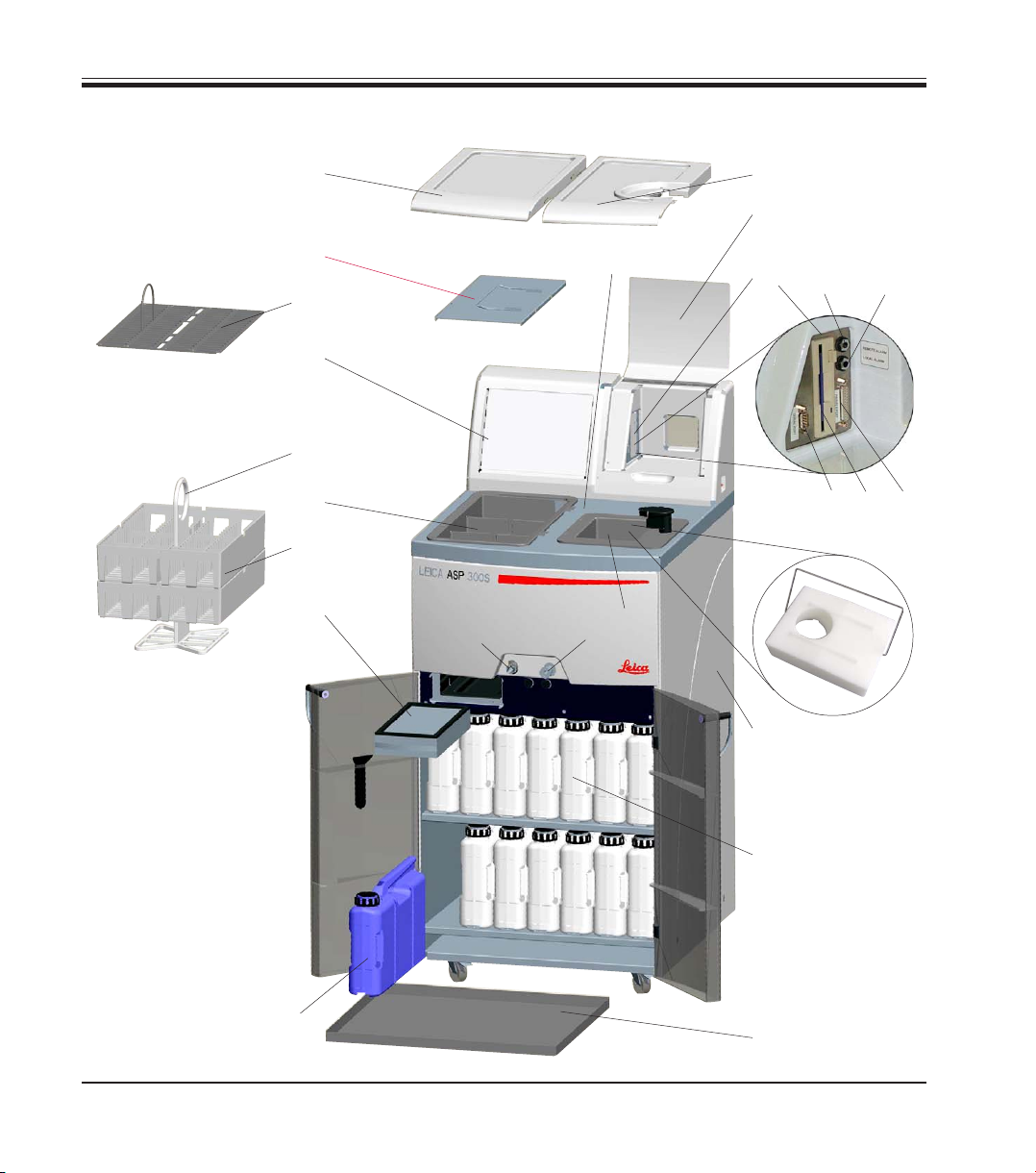
Overview - instrument components
1 - Basic instrument - processor module
2 - Basic instrument - reagent module
3 - Wax bath lids
4 - Retort lid
5 - Touch screen
6 - Cover flap of the instrument console
7 - Instrument console comprising:
8 - Printer port
9 - Local alarm connection
10 - Remote alarm connection
11 - Floppy disk drive
12 - Serial port
13 - Activated carbon filter
14 - Condensate bottle
15 - Reagent bottle (13 units)
16 - Drip tray
17 - Wax drain connection
18 - Remote drain connection
19 - Retort
20 - Wax baths
21 - Specimen basket
22 - Lid for specimen basket
23 - Specimen basket carrier
24 - Splash protection
25 - Displacement block
Instrument components and accessories
The processor module contains three paraffin
wax baths, a processing retort, and also a touch
screen with integrated key symbols as well as
the electronic components.
The cassettes are held in three baskets (21), each
of which has a capacity of up to 100 cassettes.
All processing occurs in the stainless steel retort
under the pressure, vacuum and temperature
conditions selected.
The quick-connect reagent bottles are stored in
the reagent cabinet.
Leica ASP200 S
13
Page 14

3. Instrument components and specifications
3.2 Specific instrument options
• Reagent Management System option (RMS) that displays the usage
(length and frequency of use) of each reagent and also allows automatic
ordering of reagent sequence, thus eliminating the need to physically
move reagent bottles. After renewal of one or more reagents in a sequence, the RMS automatically uses the reagents in order of increasing
cleanliness.
• In-process fluid recirculation ("tidal agitation") for continuous and
efficient mixing of fluids.
• Remote fill/drain system – can drain and refill reagent bottles from bulk
containers via the retort and a hose plugged into the processor module
while the user is fully protected against coming into contact with
reagents.
• Remote wax bath fill/drain feature.
• Optical fluid level sensor.
• Active paraffin wax solvent removal feature that increases the life of the
wax by extracting and condensing contaminating solvents.
• Magnetic stirrer – to gently circulate reagents, ensuring uniform reagent
temperature.
• Programmable finish time for processing programs.
• Three-step retort drain feature (adjustable) minimizes reagent carryover.
• Specimen processing under pressure, vacuum, alternating pressure /
vacuum cycles or under ambient pressure.
• Four user-programmable clean programs. The clean programs
automatically skip any steps not required to complete the clean.
14
Operating Manual V 1.1 – 03/2009
Page 15
3. Instrument components and specifications
3.3 Standard delivery - packing list
The basic version of the Leica ASP200 S includes the following parts: Part no.
1 Leica ASP200 Basic Instrument
1 Set of power cords
230-240 V version:
1 Mains cable "D" 14 0411 13558
1 Mains cable "UK" ST-BU F-5A 14 0411 27822
100-120 V version:
1 Mains cable "USA-C-J" 14 0411 13559
1 Jumper cable - mains 14 0411 34604
1 ASP300 S basket set, consisting of:
1 Basket carrier 14 0480 43578
2 Specimen baskets with integrated spacers 14 0476 43569
1 Cover for first basket 14 0476 43362
1 Displacement block 14 0480 37127
1 Remote fill/drain hose 14 0476 34716
1 Paraffin drain hose 14 0476 34721
1 Funnel 14 0476 43631
1 Lubricant, Molykote 111, for valves and O-rings 14 0336 35460
2 Activated carbon filters, assy. 14 0476 34150
1 Magnetic stirrer, complete 14 0476 34202
1 Paraffin wax scraper 14 0476 35923
14 Reagent bottles, plastic (13 in instrument) 14 0476 34274
1 Condensate collector, plastic (in instrument) 14 0476 34278
1 Drip tray (in instrument) 14 0476 34145
1 Splash protection 14 0476 34770
1 Maintenance kit (2 replacement lids, 9 o-rings) 14 0476 35921
1 Maintenance kit for pump (in instrument) 14 0476 35922
2 Sets of labels for reagent bottles, set of 15 each 14 0476 35792
1 Remote alarm plug 14 6844 01005
1 Operating manual for Leica ASP200 S, multi-language 14 0480 80001
1 3,5" HD-diskette, blank, DOS-formatted, (on rear of console cover)
Please check all delivered parts against the packing list and against your order to
verify whether the delivery is complete!
local Leica Sales Office immediately.
Leica ASP200 S
If there is any difference, please contact your
15
Page 16

3. Instrument components and specifications
3.4 Technical Data
Nominal voltage: Two factory-preset voltages (not user-adjustable):
100 to 120 V or
230 to 240 V
Nominal frequency:
Main fuses: Two fast-blowing melting fuses, 20 x 5 mm, UL-approved
Nominal power: 1000 VA
Dimensions, (W x D x H), in mm: 595 x 680 x 1,325
Dry weight, unpacked: approx. 160 kg
Weight, packed: 220 kg
Operating temperature range: 15 °C to 35 °C
Relative humidity: 10 % to 80 %, non-condensing
IEC 1010 classifications: Protective class 1
Altitude: 2500 m maximum
Local / remote alarm relays: 30 V DC, maximum 2 A
50 to 60 V
• for 100 to 120 V ; F 10 A 250 VAC
• for 230 to 240 V ; F 5 A 250 VAC
Pollution degree 2
Overvoltage installation category II:
• 800 V impulse (120 V systems)
• 1500 V impulse (240 V systems)
2 connections:
Both single voltage-free, changeover contacts
(both Normally-Open and Normally-Closed
connections available)
Paraffin wax baths
Number of baths: 3
Volume (liters): 4.3 l per bath
Melt time: approx. 10 hrs
Temperature: 40 to 65 °C
Temperature accuracy:
+ 1 K
16
Operating Manual V 1.1 – 03/2009
Page 17

3. Instrument components and specifications
Retort
Capacity: max. 250 cassettes
Reagent volume (in liters): 4.3
Temperature (paraffin): 40 to 65 °C
Temperature (processing reagents): ambient or 35 to 55
Temperature (cleaning reagents): 50 to 65 °C
Temperature accuracy:
+ 1 K
Filling time: approx. 90 sec
Drain time: approx. 80, 120, 140 sec (adjustable)
Impregnation vacuum: -70 kPa (g)
Impregnation pressure: 35 kPa (g)
Fill vacuum: -70 kPa (g)
Drain pressure: 35 kPa (g)
General
Reagent bottles: 10
Cleaning solution bottles: 3
Maximum bottle volume: 4.3 l
Printer: Optional accessory
Pretest check: ON/OFF
Fluid level sensor: ON/OFF
Recirculation (pump in/out): ON/OFF
(a) Time before 1st cycle: 16 min
(b) Time between cycles: 20 min
System setup
Password status: Supervisor / User
Type of password: alphanumeric, freely selectable
Reagent Management Status: ON/OFF
Software access control (lock mode): ON/OFF
°C
Leica ASP200 S
17
Page 18

3. Instrument components and specifications
3.4 Technical Data (continued)
Hardware and Software:
• Large color Liquid Crystal Display (LCD) and touchscreen.
• User-friendly, intelligent software.
• 3,5" floppy drive and printer port.
• Alarm system with two remote alarm sockets.
• Password-protected instrument supervisor mode.
• Multiple specimen protection system.
Capacities:
• 15 programs that consist of up to 10 reagent and 3 paraffin wax steps.
• Time per program step: 0 to 99 hours, 59 minutes.
• Delay time: max. 7 days.
• Up to 250 cassettes can be processed simultaneously.
• Four user-programmable retort clean programs.
• Wax clean program.
• 10 reagent bottles.
• 3 wax baths.
• 3 cleaning solution bottles.
• 1 condensate bottle.
• Reagent temperature adjustable from 35 °C to 55 °C
or ambient.
• Paraffin temperature adjustable from 40 °C to 65 °C.
• Choice of three retort drain rates of
80, 120 and 140 seconds.
• Up to 100 reagent names in memory.
18
Operating Manual V 1.1 – 03/2009
Page 19

3. Instrument components and specifications
3.5 Compatible reagents
The following reagents may be used in the Leica ASP200S:
Fixatives
1. Formalin, buffered or unbuffered
2. Formalin saline
Dehydration
1. Ethanol 4. Butanol
2. Isopropanol 5. Industrial Methylated Spirits
3. Methanol
Clearing
1. Xylene
2. Toluol
3. Chloroform *
Paraffin wax
1. Paraffin
*
*
Prior to using these reagents, contact your
Leica representative or Leica directly for in-
formation on necessary protective measures.
Leica ASP200 S
Caution:
Reagents other than those listed here may damage some components of the instrument.
Do not use acetone, benzene or trichlorethane in the instrument.
Fixatives containing mercuric salts, acetic or picric acid will
corrode metallic components in the instrument and shorten
instrument life.
If you choose to work with such fixatives, it is essential to
perform a clean cycle which contains multiple water rinses
each time after use, to minimize damage.
In addition, we recommend frequent and regular preventive
maintenance by the Leica Technical Service.
19
Page 20
4. Setting up the instrument
4.1 Site requirements
• The instrument must be set up in a clear space
of about 650 x 700 mm on a non-vibrating base.
• Room temperature constantly between +10 °C
and +35 °C.
• Relative humidity maximum 80%, non-condensing.
• Avoid vibrations, direct sunlight and heavy
variation in temperature.
Moving the instrument
4.2 Electrical connection
Caution!
The instrument MUST be connected
to an earthed mains power outlet
socket.
It is recommended that the ASP200S
be plugged into a wall socket that
has Ground Fault Circuit Interruption
(GFCI) protection – as an additional
electrical safeguard.
Make sure to use the appropriate
mains cable for the local voltage
supply (wall outlet).
The chemicals to be used in the
Leica ASP200S are both flammable
and noxious. The Leica ASP200S
must be set up in a well ventilated
area free from any ignition sources.
Do not operate the instrument in
rooms with explosion hazard.
When the instrument has been unpacked (see
Unpacking instructions on the outside of the shipping container), it must be grasped only at the
points indicated by ‘ ‘ to move it to its final setup
location. Once it has reached this position, the
brakes on the instrument rollers must be engaged immediately.
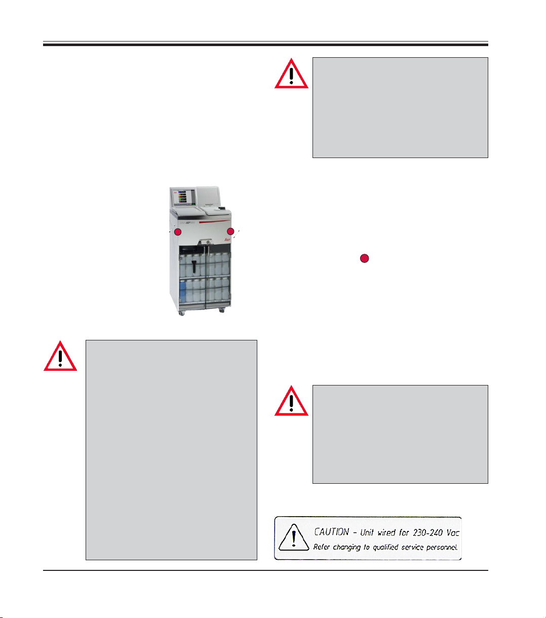
• Check the voltage label (Fig. 3) on the rear of
the instrument to ensure that the instrument
delivered is set to the correct voltage range.
Severe damage may occur if the instrument is connected to a power
supply voltage other than that to
which it was originally set.
The power supply voltage for the instrument is factory preset, and CANNOT be altered by the user.
20
The instrument must be set up so
that the power switch on the rear of
the instrument (
be reached at all times.
item 42 in fig. 4) can
Fig. 3
Operating Manual V 1.1 – 03/2009
Page 21
4. Setting up the instrument
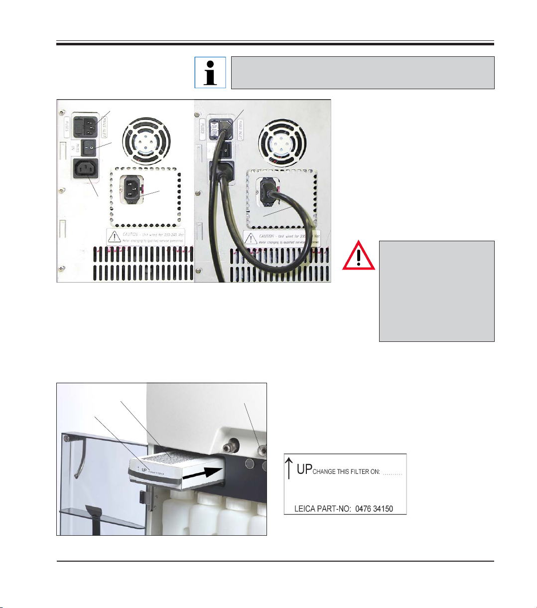
Connecting the instrument
to mains
41
42
40
43
Illustration on the left
Electrical connections at the
rear panel of the instrument.
Once the instrument has been switched on, the mains
switch (ON/OFF) (42) should always remain in position “ON“.
37
38
Illustration on the right
Correct connection of the
cables
• Connect the mains cable (37) to
the mains power supply socket
(41).
• The jumper cable (38) which is
supplied as part of standard
delivery connects the mains
power supply output (43) to the
electronics module input (40).
Important!
The specification for
Fig. 4
connection (40) is as
follows:
100 - 120 V or
230 - 240 V,
maximum 200VA.
4.3 Installing the accessories
13
29
Leica ASP200 S
18
Fig. 5
• Place the instrument in the definitive installation position.
Activated carbon filter
• Unpack the activated carbon filter (29) and insert it into the instrument (see
Fig. 5).
Make sure to insert the filter with the correct
side facing upwards. See label
(27) at the front of
the filter – the arrow must point
upwards.
21
Page 22
4. Setting up the instrument
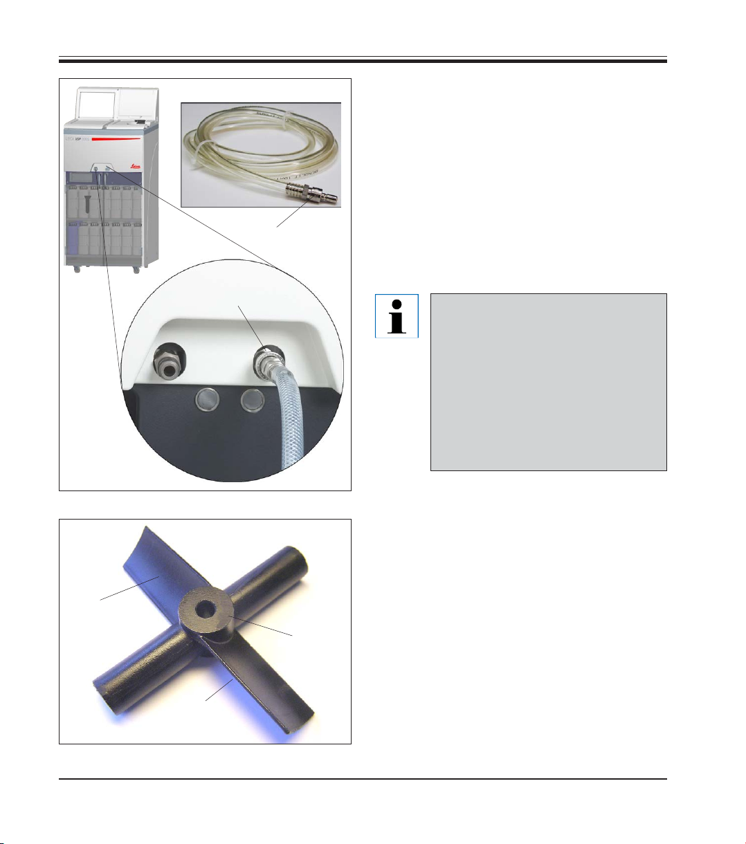
28
Remote fill / drain hose
• Connect the supplied remote fill/drain hose to
the remote drain connection on the front of the
instrument (
see Fig. 6).
• Important!
When inserting the hose into the fill/drain con-
nection (item 18 in
Fig. 6) the connecting de-
vice (28) of the hose must lock with an audible
click.
31
32
18
30
Fig. 6
If bulk containers can be located
next to the instrument during remote
filling and draining, the hose may be
shortened to improve handling and
the fill/drain rate.
If the hose is shortened, a vee-notch
can be cut into the hose end to ensure a clear passage for fluid flow.
Magnetic stirrer
• Unpack the magnetic stirrer (30,
fig. 7) and in-
sert into the retort.
• Important!
Insert the magnetic stirrer so that the convex
side (32) of the rotor blades (31) faces down.
(Fig.
8)
Inserting the stirrer incorrectly will result in
unsatisfactory stirring action.
22
Fig. 7
Operating Manual V 1.1 – 03/2009
Page 23
4. Setting up the instrument
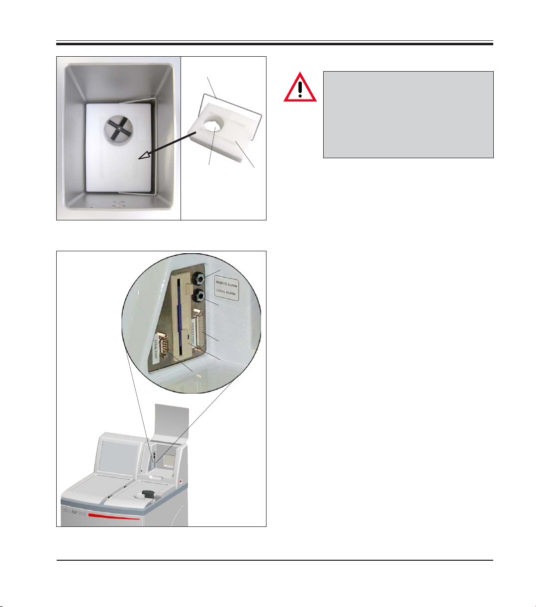
25
26
Important!
The instrument must not be operated
unless the volume displacement
block is in the retort. Otherwise,
malfunctions may cause damage to
the instrument.
27
25
• Grasp the volume displacement block (25) by
the metal clip (26) and insert into the retort so
that the hole (27) is located above the position
of the magnetic stirrer.
Inserting the Displacement block
Fig. 8
4.4 Setting up the data connections
10
9
8
11
12
6
Printer (optional)
• Lift the flap of the instrument console (6).
• Connect the printer to the printer port (8) in the
console via a standard Centronics cable
(
Fig. 9)
• A suitable printer can be recommended by
your Leica distributor.
• If conformance to electromagnetic interfer-
ence standards is essential, a specially shielded printer cable will be required.
Other connections
• For additional data transfer and storage the
instrument console is equipped with a standard 1.44 MB floppy disc drive (11) and an RS
232 serial interface (12).
Leica ASP200 S
Fig. 9
23
Page 24
4. Setting up the instrument
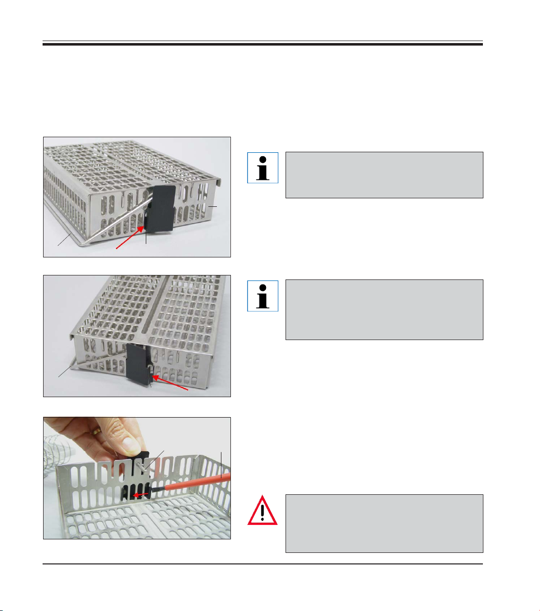
4.5 Anti-reflection clip – Installation Instructions
Anti-reflection clip – Function
The anti-reflection clip (Order no. 14 0476 44135) prevents any reflections that might otherwise be emitted from the specimen basket (3, order no. 14 0476 34193) and that could affect the level sensor in the
retort, thus causing malfunctions.
Installing the clip
The anti-reflection clips are intended for
installation on the specimen basket to
prevent reflections of the level sensor.
1
3
• Insert the left lug (2a) of the anti-reflection clip (1)
into the seventh hole (from the left) of the lower oval
openings (Fig. 9).
4
2a
Fig. 9
• Snap the right lug (2b, Fig. 10) into the seventh hole
(from the right) with light pressure.
When inserting or removing the metal
baskets into/from the retort, always do so
carefully so that they do not touch or become caught on the retort wall.
1
4
2b
Fig. 10
Changing the clip
• Once the clip is installed, the handle (4) of the specimen basket cannot be removed, as otherwise the
clip will be bent.
• To remove or replace a clip, all parts that are inside
4
5
the basket (e.g. spiral insert and separating walls)
must be removed from the basket.
• Then, insert a suitable tool (screwdriver 5, Fig. 11)
and pry the clip out from the inside.
24
Fig. 11
Once bent, clips may no longer be used
and must be disposed of. In this case, install a new clip from the standard scope
of delivery.
Operating Manual V 1.1 – 03/2009
Page 25

4. Setting up the instrument
4.6 Alarm functions
The Leica ASP200 S is equipped with 3 different
alarm functions:
Instrument alarm
This alarm is generated from within the
Leica ASP200. The Instrument alarm is used for
all alarm messages.
Local alarm
This alarm is external to the Leica ASP200 S, e.g.
in the office of the instrument operator.
The Local alarm is used when the instrument
cannot continue with the current program or operation because of a problem.
Alarm connections (optional)
If required, connect the local and/or remote
alarm systems to the alarm sockets (9, 10 in
8) at the instrument console, using the phono
jack (34) supplied (Ø 6.3 mm).
Local alarm: socket (9)
Remote alarm: socket (10)
Fig.
Remote alarm
This alarm is also external to the Leica ASP200 S.
If installed, it might typically be connected to a
remote dialer that sends an automated phone
message to the person responsible for afterhours problems
.
The remote alarm is only generated when the instrument cannot continue with a Processing program.
Note that if installed, the remote
alarm will still operate even if the
local alarm is not installed.
Both, local and remote alarm options, are relays that are voltageisolated from the rest of the instrument. When an error condition
occurs, the relevant alarm circuit
closes.
The remote alarm device connected
to the instrument must be rated at
less than 2 amp.
A maximum voltage of 30 V DC may
be present.
Leica ASP200 S
35
36
33
34
Fig. 10
Each alarm is connected to plug (34) as follows
(see Fig. 9):
Common terminal: tip (36)
connection inside
Normally Open
Contact: First sleeve (35)
connection outside
Normally Closed
Contact: Second sleeve (33)
Threaded connection
25
Page 26

4. Setting up the instrument
4.7 Switching the instrument on
Caution!
The instrument MUST be connected to an earthed mains power outlet socket.
It is recommended that the ASP200 S be plugged into a wall socket that has Ground Fault
Circuit Interruption (GFCI) protection - as an additional electrical safeguard.
• Connect the instrument to the mains power outlet socket. If applicable, switch
the mains power outlet socket ON.
•
Switch the ON/OFF switch (item 42, Fig. 2) located at the rear panel of the instrument (ON).
• Switch the ON/STOP switch at the right side of the instrument (ON).
The ON/OFF switch at the rear and the ON/STOP switch at the side should be left ON at all
times to maintain heating to the paraffin wax stations.
The ON/STOP switch at the side of the instrument may be used in an emergency to stop
the instrument during operation.
• The instrument will take a few minutes to initialize. See opposite for corresponding touch
screen display (
Fig. 11).
• After that, the FAVORITES screen will be displayed (
Fig. 12).
26
Fig.11
Screen saver
• A screen saver will operate turning the screen
off when no key has been pressed for a (user)programmable time. Press any part of the
touchscreen to restore the screen.
After having been restored, the screen will be
inoperational for a few seconds to avoid accidental activation of any keys.
Fig. 12
Operating Manual V 1.1 – 03/2009
Page 27

2
6
1
3
4
7
8
5
The following functions can be selected:
1 - Access for Service Engineers only.
2 - Access INSTALLATION menu.
3 - Abort the current program.
4 - Abort the current program and delete the cur-
rent allocation of reagents to reagent bottles
and retort.
5 - Delete all programs and reset instrument sta-
tus (all lists will be empty).
6 - Store actual instrument status on floppy disk.
7 - Display run log.
8 - Restart instrument.
4. Setting up the instrument
System Diagnostics Menu
If, during initialization, "Touch here ..."
refer Fig. 11) is touched and subse-
(
quently the supervisor password is
entered, the SYSTEM DIAGNOSTICS
menu+ (Fig. 13) opens up, giving access to standard instrument settings.
Attention!
These settings must be modified by
experienced operators only. Serious instrument malfunctions may
occur if any settings are modified
wrongly.
Fig. 13
To exit this menu the instrument has to be restarted: press RESTART APPLICATION.
For instrument reinitialization, press YES to confirm the query "ARE YOU SURE YOU WANT TO ..."
Fig. 14).
(
Such prompts are issued before all
important, irreversible steps.
This allows the operator to undo
changes caused by accidental key
strokes.
• Initialization starts again from the screen
shown in Fig. 11.
Leica ASP200 S
Fig. 14
27
Page 28

4. Setting up the instrument
4.8 Touchscreen functions
Fig. 15
Button symbols
Press the button to activate the corresponding function on the Leica
ASP200 S touchscreen.
All buttons have a uniform design for easy identification.
The buttons may contain text labels or graphical icons.
The Leica ASP200S is programmed and operated via a colored
LCD touch screen.
The control software contains an on-line help feature where
detailed information on the operation of each screen, on error
messages and on the software functions can be found.
Help can be accessed from any screen by
pressing the HELP button.
28
Enabled
Buttons on the Leica ASP200S have different appearances depending on
whether they are enabled or disabled.
A button is disabled if the function that it performs is not applicable at the
moment.
Disabled
Disabled icons have a thinner border than active ones as shown here.
If a disabled button is pressed, a help text will be displayed, explaining why
this particular button is disabled.
Operating Manual V 1.1 – 03/2009
Page 29

4.9 Checklist for first operation
Once the instrument is ready to be switched on, the menus below have to be accessed to
set the required parameters.
For detailed instructions on each individual parameter, refer to the On-line help feature.
4. Setting up the instrument
Screen
→ Press button
→→
→
→
→→
→
→
→→
→
or
→
Parameter settings
Enter carbon filter age warning and pump
warning threshold.
Enter instrument name and select language.
Activate printer (optional).
Set all parameters as required, especially
wax bath set temperature.
Check whether date and time are correct.
Add the desired reagents and edit the warning
thresholds when "REPLACE REAGENTS" will be
displayed.
Allocate a reagent to each station.
Fill the reagent stations (bottles), either via remote drain/ fill function (SMART SCREEN) or
manually (REAGENT STATUS).
→
→→
Leica ASP200 S
→
→
Create the programs you need.
Both processing and retort cleaning programs
can be copied and modified.
Allocate the most popular programs to the
FAVORITES menu and, if desired, set a finish
time for these programs and allocate a symbol.
Fig. 16
29
Page 30

4. Setting up the instrument
4.10 Switching off the instrument
If the instrument must be completely switched off or disconnected from the
mains, please proceed as follows:
• Press MENU to go to the MENU FUNCTIONS screen,
• there press the button EXIT APPLICATION.
A message appears stating that all data will be saved and the system will
now be shut down.
When all data has been saved, the following message appears.
Fig. 19
30
Fig. 20
The instrument can now be switched off by means of the ON/STOP switch
on the right of the instrument and by means of the ON/OFF switch on the
back of the instrument (
item 42 in fig. 4).
Press the RESTART button to restart the instrument.
Caution!
The Multistainer must only be completely switched off in this
way. Otherwise this can result in serious damage to the instrument's hardware and data loss.
Operating Manual V 1.1 – 03/2009
Page 31

5.1 Setting up the instrument parameters
5. Operation
→
5.1.1 System setup
From the start screen, press MENU to go to the MENU FUNCTIONS screen,
then press MORE to go to the MORE MENU FUNCTIONS screen.
Fig. 17
Fig. 18
In the window
MORE MENU FUNCTIONS
press
SYSTEM SETUP.
Leica ASP200 S
The
SYSTEM SETUP screen is divided up into five selection fields:
• Program Options
• Display/Buzzer
• Date/Time
• Security
• Instrument
Fig. 19
31
Page 32

5. Operation
Fig. 20
PROGRAM OPTIONS
Select the options with which programs are executed here. Press a button
to change the associated value.
• STATION ALLOCATION: by Age or Sequential
by Age - RMS is activated, reagents will automatically be
used in order of increasing cleanliness.
Sequential - reagents will be used in sequential order of stations.
• WAX BATH ORDER: Auto or 1.; 2. ; 3.
Can only be activated, when STATION ALLOCATION is set to "Sequen-
tial" - otherwise the order of wax baths will be managed by the RMS.
• PROMPT FOR NUM BLOCKS: Enabled or Disabled
Enabled - When starting a program, the actual number of
blocks must be entered.
This is recommended with the RMS being enabled.
Disabled - Number of blocks can be entered optionally
(not mandatory to enter no. of blocks).
DATE / TIME
Be sure to verify that the date and time entered do actually correspond to
the local time/date, as this will ensure that all programs are carried out
correctly.
Press the buttons to access the entry windows where settings or corrections can be made, if necessary.
32
Date and time setup screen
Fig. 21
Fig. 22
Operating Manual V 1.1 – 03/2009
Page 33

Fig. 23
5. Operation
DISPLAY/BUZZER
• The number next to DISPLAY OFF indicates the remaining time (in min)
until the screen saver (after the last user action) is activated.
• LCD CONTRAST can be set from 0 to 14.
• The BUZZER VOLUME can be set between 1 and 10.
INSTRUMENT
Press WAX BATH SET TEMP. to open the input screen (
bath temperature.
Set the temperature according to the value required by the wax used.
Select the highest permissible temperature for the wax to ensure that a minimum loss of temperature occurs when filling the retort.
Fig. 24) for the wax
Wax temperature and run
options screen
Leica ASP200 S
Access the RUN OPTIONS
function to display the options selected for the current program.
The options selected will be
applied to ALL programs!
A printer option will be displayed only, if a printer has
been configured for the instrument.
The individual options are
described in chapter 5.3.1.
Fig. 24
33
Page 34

5. Operation
5.1.2 Access levels
SECURITY
Access rights to the instrument are managed here as
user profiles.
Administrator mode is disabled on delivery.
Fig. 25
SUPERVISOR PASSWORD: Enabled or Disabled
Enabled - Two different types of user profiles are available.
A password is required for supervisor level access to the instrument. Enabling SUPERVISOR MODE already requires
entering the password.
The Leica ASP200 S may be configured to allow two levels of user access.
"Operator" symbol
"Supervisor" symbol
→
Operator access level:
• Operators may run programs and view results. On this level, the
OPERATOR symbol is displayed in the upper right corner of the touch
screen; all enabled buttons are surrounded by a black border.
Supervisor access level:
• Supervisors may perform all Operator functions, and additionally create
programs and perform the instrument set up functions.
At the Supervisor access level, a status line is added to the SMART
SCREEN functions containing information on the retort and wax baths
Fig. 49, page 49).
(see
• To access Supervisor level, press SUPERVISOR enter the required password and confirm. When entering the password the SUPERVISOR symbol will be displayed instead of the OPERATOR symbol and all enabled
buttons will be surrounded by a black border instead of a blue one.
Disabled - Default state of the instrument. All instrument and
software functions of the ASP200S are fully
accessible to all staff.
34
Operating Manual V 1.1 – 03/2009
Page 35

LOCK MODE: Enabled or Disabled
The Leica ASP200S provides a feature called
"Lock" to prevent access to any operations of the
Leica ASP200 S to unauthorized users.
Enabled:
The LOCK button is enabled in the menu functions. To enable, a password has to be entered.
When activated, LOCK prevents any user input,
until after a password has been entered.
Disabled:
All functions can be accessed at any time until
the screen saver turns off the screen.
Fig. 26
Entry keyboard
The keyboard is displayed any time text needs to be entered.
• The keyboard headline (1) tells you what kind of text to enter.
• 30 characters can be entered into each entry field, though sometimes
not all characters entered can be displayed.
5. Operation
Leica ASP200 S
1
Important keys
Shift :
To shift to upper case symbols.
AltGr :
Permits the entry of special characters.
<— :
Deletes the previous character.
Delete :
Deletes the entire line.
Fig. 27
35
Page 36

5. Operation
5.1.2 INSTALLATION menu
→
Assigning an instrument name
→
Use this menu to set the name of the instrument,
the language of the user interface and configure
a connected printer.
The serial number of the instrument and the current software version are entered at the factory
and cannot be edited.
Selecting a language
Press LANGUAGE to open the SELECT LANGUAGE
menu.
Select the desired language there and press OK.
↓
Fig. 28
↓
Fig. 29
Press INSTRUMENT NAME to display the keyboard.
Enter a name (20 characters maximum) for the
instrument.
The instrument name is also displayed on the
FAVORITES screen.
36
↓
Fig. 30
A message box will prompt you to restart the
instrument in order to display the user interface
in the selected language. Press YES to restart the
instrument and display the user interface in the
new language.
Operating Manual V 1.1 – 03/2009
Page 37

Setting the altitude of the installation location (in meters above sea level)
This is important as it affects the actual pressure in
the retort.
Press SITE ELEVATION (metres), enter the value in
→
the number field and press OK.
This parameter (in meters) must be entered to ensure
that the ASP200S makes the appropriate corrections
when calculating the proper pressure or vacuum.
Fig. 31
Updating software:
New versions of the ASP200S operating software are provided on diskette.
Such upgrades generally contain two to three diskettes.
Do not perform a software upgrade if you do not have all of the
diskettes in the upgrade package.
Read the instructions in the upgrade pack with care, as they
may contain additional version-specific information as well as
new or modified procedures, parameters and data that must be
loaded or modified to ensure that the new software version
functions correctly.
5. Operation
↓
↓
Leica ASP200 S
1. Make a backup copy of the instrument’s current data. You will need an
empty, formatted diskette for this purpose.
2. Insert "Disk 1" (or similar) of the software upgrade into the diskette drive.
3. Press UPDATE SOFTWARE, dismiss the safety queries with YES / OK and
follow the onscreen instructions.
Insert "Disk 2" into the diskette drive when prompted. Continue with the
remaining disks (if any).
4. When the update process is complete, the instrument’s software will
reboot – the screen will switch off and restart as it would when switching the instrument off and back on.
Fig. 32
37
Page 38

5. Operation
Configuring a printer
→
↓
↓
→
• The Leica ASP200S works with any printers that are com-
• With a Centronics standard cable, connect the printer to the
• In the SELECT THE PRINTER TYPE window, highlight the print-
Fig. 33
Printing run logs
Printing is possible when the PRINT symbol is displayed.
For the PRINT symbol to be displayed, a printer must have been
configured for the instrument.
On the INSTALLATION screen press PRINTER TYPE to
display the list of the printers that can be connected.
patible with commercial PC’s.
printer port. (See
er that is connected to the instrument and press OK.
If the printer driver you connected is not listed, try
a similar printer of the same manufacturer.
If this approach does not work, call Leica Technical Service to have the required printer driver installed.
chapter 4.4, Fig. 9)
Installing custom help
38
The following lists and protocols can be printed:
• reagent list
• stations list
• reagent status list
• all programs
• run log
• error log
See
chapter 5.6 "Online help" on page 59.
Operating Manual V 1.1 – 03/2009
Page 39

5.1.3 Editing the reagent list
Adding new reagents
1. Enter the reagent name and allocate the new reagent to the reagent
2. Define the stations (bottles) that will be filled with the new reagent.
3. Fill the stations (bottles) according to the reagent list.
Enter reagent names
Enter reagent names via the REAGENTS screen.
You must be logged on at supervisor access level to proceed.
• From the start screen, press MENU to go to the MENU FUNCTIONS
→
• The MORE MENU FUNCTIONS screen will appear. Press REAGENTS.
• The SET UP REAGENTS AND WARNING THRESHOLDS screen opens.
• To add a reagent:
5. Operation
group it belongs to.
screen, then press MORE.
• Press INSERT to display the keyboard.
• Enter the new reagent name.
• Press OK to confirm.
• You will then automatically be prompted to select the reagent
group:
Leica ASP200 S
Select the reagent group
Fig. 35
Allocate the new reagent to the desired group
and press OK to confirm.
Fig. 34
39
Page 40

5. Operation
Allocation of reagents to the correct reagent group is the basis for compatibility monitoring.
Allocation to the wrong reagent group can lead to reagent cross contamination.
Changeable parameters
Fig. 36
Entering / modifying reagent thresholds
f warning thresholds are required for a certain reagent, enter them as follows:
I
• Highlight the reagent to be modified, either by pressing the reagent name
or using the UP/DOWN buttons.
• Press the header of the parameter to be changed - the corresponding
entry screen opens.
• Enter a new threshold or - if no warning is desired - press CLEAR to
remove the threshold altogether.
• Press OK to confirm.
The respective threshold value applies for all reagent stations
containing the same reagent.
Changing reagent names or reagent groups
If a reagent is already used in a program, it can neither be
renamed nor can it be allocated to another reagent group!
The corresponding symbols will be disabled (i.e. they will not
be surrounded by a blue border).
If a reagent is renamed, all stations and programs linked to that
reagent need to be reedited as well!
40
• Highlight the reagent the name or group of which you wish to change.
• Press the corresponding headline key symbol.
• In the entry window (or via the keyboard), enter the new reagent group
allocation / the new reagent name.
• Press OK to save the new reagent group / reagent name.
Fig. 37
Operating Manual V 1.1 – 03/2009
Page 41

↓
↓
↓
5. Operation
Deleting reagents
• Highlight the reagent to be deleted in the SET UP REAGENTS AND
WARNING THRESHOLDS screen.
• Press DELETE.
• Press OK in the screen to confirm the reagent is deleted.
Please remember that a reagent which is already used in a
program cannot be deleted.
Fig. 38
Adding new reagents to stations
Go to SMART FUNCTIONS to remote-fill the reagent bottle from an external
bulk container
or
fill the reagent bottle manually.
After filling a bottle manually the bottle must be defined as full.
For that purpose:
• Press MENU to access the MENU FUNCTIONS screen.
• Press REAGENT STATUS.
• In the reagent list, highlight the station/ reagent that has been filled
manually.
• Press SET AS FULL to mark the station as "full".
Leica ASP200 S
Upon activation of the RMS all warning thresholds for the selected reagent are automatically reset to "0".
41
Page 42

5. Operation
5.1.4 Viewing the program list
→
This list (Fig. 39) displays all programs currently existing in the
ASP200 S.
You can create:
• Up to 15 processing programs
• 3 retort cleaning programs
• 1 wax cleaning program.
At supervisor access level:
• the processing program names
can be edited.
• new processing programs can be
created and existing ones can be
deleted.
Fig. 39
Important!
New processing programs are created by copying existing
ones. Therefore, the list must contain at least one program at
all times.
42
Program duration cannot be specified. – It is determined by the total duration of all program steps, plus the estimated fill and drain times. To alter the
duration of a program, the duration of one or more individual program steps
has to be modified.
Retort and wax cleaning programs are predefined. They cannot
be renamed, added or deleted.
Operating Manual V 1.1 – 03/2009
Page 43

5.1.5 Adding and/or modifying programs
Creating a new program
• Make sure you are logged on at supervisor level.
• In the VIEW/EDIT PROGRAMS screen (
similar as possible to the program you wish to create. (This minimizes the
number of modification steps to be carried out).
• Press COPY to copy the selected program. The new program will have
the same name as the program copied, however, the figure "(2)" will be
added to indicate the change.
• Highlight the line containing the new program.
• Press PROGRAM NAME at the top of the table to display the keyboard.
• Enter the new program name.
Editing program steps
Fig. 40
• Press EDIT (refer
• In the headline you will find the PROGRAM NAME.
• The colors on the left border of the table indicate the reagent groups to
which the reagents belong.
• The program steps are displayed in the order in which they are carried
out. For each program, up to 13 steps can be defined.
The following characteristics of each program step can be edited:
• Reagent name.
• Duration of step
(with the exception of fill and drain steps).
• Retort temperature
(if "Ambient" is selected, the retort temperature indication remains empty).
• Type of pressure and/or vacuum cycle.
• Retort drain time.
• Delay step.
5. Operation
Fig. 39) highlight a program as
Fig. 39) to access the PROGRAM STEPS screen.
Leica ASP200 S
43
Page 44

5. Operation
Editing program steps
• To edit a step, highlight the corresponding line and press the respective
headline.
• In the entry windows that pop up enter / select the program step settings.
↓
44
↓↓ ↓ ↓
Fig. 41
Operating Manual V 1.1 – 03/2009
Page 45

Editing program steps (continued)
Setting a delay step
A step that is nominated as a delay step, will be extended to ensure that a
program will finish at a specified time ("Finish Time"). To set a delay step:
• Highlight the program step you wish to define as delay step.
• Press DELAY.
The delay symbol is moved to the selected step, thus defining the step as
delay step.
Copying program steps
• Highlight the step you wish to copy.
• Press COPY.
• If required, modify properties of the step.
• Use the MOVE UP / MOVE DOWN buttons to move program steps up or
down within an existing program without having to recreate those steps.
5. Operation
Remember that a program step cannot be copied if the program
already contains the maximum number of 13 steps.
Leica ASP200 S
Deleting program steps
To delete a step from a program:
• Highlight the step you wish to delete.
• Press DELETE.
Remember that it is not possible to delete a step from a program
containing only one single step.
Programs must consist of at least one step.
45
Page 46

5. Operation
5.1.6 Favorites
In the ASP200 S you can define up to five Favorites.
Favorites can be programmed to end either
• "as soon as possible" (ASAP) or
• at a predetermined finish time.
↓
46
↓
Fig. 43
Fig. 42
Adding and/or modifying favorites
• Highlight the program line to be altered.
• Press PROGRAM NAME.
• Select the desired program and press OK to confirm.
Setting a finish time
• Press FINISH TIME.
• Enter the finish time (24-hour clock). Select ASAP, if the program finish
time is not to be delayed.
• Press OK to confirm.
If a preprogrammed finish time is assigned to a favorite, a delay will automatically be inserted into the program at the nominated "Delay Step" to ensure that the program finishes at the
preprogrammed time.
Operating Manual V 1.1 – 03/2009
Page 47

↓
↓
Fig. 44
5. Operation
Assigning a finish day
In addition to the finish time, you can also define a specific day of the week
when a Favorite is to finish.
• Press DAY.
• Select the desired week day in the list and press OK to confirm.
Assigning a symbol to a "Favorite"
Assigning a specific symbol to a favorite makes it easy to recognize at any
time.
• Press ICON in the table header.
• Select the desired symbol and press OK to confirm.
The first symbol in the list is empty – select this option, if you
do not want to assign a symbol to a specific program.
Leica ASP200 S
Fig. 45
Deleting a "Favorite"
• Highlight the Favorite you wish to delete.
• Press DELETE. The Favorite is deleted without any further queries.
The "Favorite" is only deleted from the FAVORITES list. The program itself is not deleted.
47
Page 48

5. Operation
5.1.7 Editing the stations
→
Adding / changing reagents
Highlight the desired station, either by pressing
the reagent name or using the UP/DOWN buttons.
• Press REAGENT NAME.
• The SELECT REAGENT entry window pops up.
Only those reagents that are compatible with the respective station
will be available for selection.
• Highlight the desired reagent and press OK to
confirm.
→
The list below (
reagents currently defined in the instrument.
Fig. 46) shows all stations / allocated
↓
Fig. 46
Allocating reagents
• Only processing reagents (except paraffin)
can be allocated to stations 1 – 10.
• Only a cleaning reagent can be allocated to
station 11.
• Only a cleaning alcohol can be allocated to
station 12.
• Only cleaning water/detergent can be allocated to stations 13 and 13-ext.
• Only paraffin wax can be allocated to the wax
baths.
48
Operating Manual V 1.1 – 03/2009
Page 49

5.1.8 Reagent groups
5. Operation
→
→
In this screen (
reagent group in the graphic program display.
Fig. 47) you find the colors used for each
↓
Fig. 47
Leica ASP200 S
Selecting a new color for a reagent group
• Highlight the line containing the reagent color you wish to change.
• Press COLOR in the table header: the entry window SELECT COLOR pops
up.
• Select the desired color and press OK to confirm.
• If you want to close the entry field without changing the color, press
CANCEL.
• The new color will be used in all stations to symbolize the reagent group
it has been allocated to.
49
Page 50

5. Operation
5.2 Reagent handling
5.2.1 Fill/drain reagents (other than wax)
1. Manually changing the reagents
• Remove the appropriate reagent bottle from the reagent cabinet, remove
the bottle screw cap.
↓
↓
• Drain/refill the reagent by pouring to/from a bulk container. Use the included funnel for clean filling.
• On the REAGENT STATUS screen, verify correct allocation and set the
reagent bottle as full.
2. Use the "Remote Fill / Drain" features
7
• Connect the supplied remote fill/drain hose to
the remote drain connection (7) on the front of
the instrument.
refer Fig. 6, Chapter 4.3, page 22).
(
Important!
Ensure that the hose is pushed all of
the way onto the connection, until a
clear click is heard.
• Put the loose end of the remote fill/drain hose
into the desired container for the drain/fill
operation as desired.
Fig. 48
While performing a reagent fill/drain, ensure that the remote
fill/drain hose is securely placed in the remote container and is
not removed from the container until the operation is fully completed as pressurized air is used to clear the hose after each
fill / drain.
The hose should therefore not be removed from the bulk container until this cleaning step is complete.
50
Operating Manual V 1.1 – 03/2009
Page 51

→
5. Operation
Fill / drain reagents
In FAVORITES press MENU. In MENU FUNC-
TIONS, press SMART SCREEN.
Status bar
displayed in administrator mode
Select station Press key symbol
Fig. 49
The SMART SCREEN (
Fig. 49) pops up. The smart
screen is the initial screen for manual operation
of the instrument.
The following steps should only be
carried out by trained laboratory
personnel, experienced in handling
reagents.
Status bar
The following values are displayed:
• Retort temperature and pressure
• Wax bath temperature
• Value of the retort level sensor
• Retort lid – open or closed
Remote drain
• On the screen, select reagent bottle no. 3 and
the bulk container (Remote).
Then press STATION DRAIN.
• Make sure no reagent has been spilled.
Leica ASP200 S
Remote fill
• On the screen, select an empty reagent bottle
(no. 3) and the bulk container (Remote).
Press STATION REFILL.
• The remote fill procedure should be complet-
ed in less than 170 seconds.
• Make sure no reagent has been spilled.
Fig. 50
51
Page 52

5. Operation
5.2.2 Changing the wax
17
36
Draining the wax
• Connect the paraffin drain hose (36) to the wax
drain connection
ment (
Fig. 51) and insert the loose end of the
(17) on the front of the instru-
hose into a collecting container.
Make sure that the hose is pushed
all of the way onto the O-rings of the
wax drain connection.
While performing a paraffin drain,
ensure that the paraffin drain hose
is securely placed in the remote
container and is kept in place until
the completion of the operation,
as the hose is automatically purged
with air upon completion of the
drain.
The hose should therefore not be removed from the remote container
until this cleaning step is complete.
52
Fig. 51
In the FAVORITES screen press SMART SCREEN
→
(see previous chapter).
• Select the wax bath to be drained and the re-
+
→
mote container ("Remote",
Fig. 52).
Then press STATION DRAIN.
Fig. 52
• Several safety queries will be displayed, each
of which has to be confirmed individually in
order to continue.
Operating Manual V 1.1 – 03/2009
Page 53

Filling with wax pellets
→
1
→
Fig. 53
5. Operation
•
Fill the wax bath with wax pellets up to the maximum level line (1 in
prox. 3.5 kg pellets per wax bath (Leica pellets).
• Press BACK and REAGENT STATUS to access
the reagent status table (
wax bath you just filled and press SET AS FULL.
• After about 90 minutes, add another 0.5 kg of
wax pellets.
• Do not insert the splash protector during the
heating phase.
• The pellets will take a total of approx. 10 hours
to melt.
Important!
During the melting process, the paraffin level may NOT drop below the
MIN level (pos. 2,
• Once the paraffin is completely molten, rein-
sert the splash protector.
Fig. 54). This requires ap-
Fig. 53). Highlight the
Fig. 54).
Leica ASP200 S
Software control
• Paraffin pellets have to be completely molten
before the ASP200S allows any programs to
be run.
2
The instrument software calculates when the
wax will be ready for use and selects program
starting times accordingly, i.e. the paraffin will
definitely be molten when it is required for the
first paraffin step.
Fig. 54
53
Page 54

5. Operation
Adding molten paraffin
To avoid damage to the thermal fuse, molten wax that is added to the wax baths may
have a maximum temperature of 70 °C.
→
→
↓
Fig. 55
→
• If filling with molten wax, do not fill above the
MAX level (see Fig. 54) on the wall of the wax
baths.
• After a wax bath has been filled, it must be
marked as "full" in the REAGENT STATUS
screen.
Software control
If the wax baths are filled with molten wax, it is possible to override the
melting time calculation.
In administrator mode, open
SERVICE FUNCTIONS (
Press TIME UNTIL WAX MELTED.
→
Fig. 54).
A safety query will be
displayed. Dismiss it
with YES.
Enter the desired delay
in the time screen and
press OK.
54
Fig. 56
Only change the melting time if you are absolutely certain that the new time entered is
correct.
If the instrument attempts a paraffin step with the paraffin only partly molten, severe
instrument malfunctions may occur.
Operating Manual V 1.1 – 03/2009
Page 55

5.3 Running programs
Programs can be started from two different screens:
5. Operation
FAVORITES
Fig. 57 Fig. 58
In the ASP200 S you can define up to five Favorites.
A "Favorite" is a processing program that is frequently used and therefore allocated to the
FAVORITES list.
All settings are already programmed. Only the
number of blocks has to be entered (if this function is enabled).
Starting a "Favorite"
To start a Favorite, press the corresponding symbol on the Favorites screen - the program will be
started immediately.
After the program has been started, its finish
time and/or other program parameters can still
be changed as with any other program.
ALL PROGRAMS
In the Favorites screen, press ALL
PROGRAMS to access the All Pro-
grams screen, where all existing
processing programs are displayed.
• Press the symbol corresponding to the pro-
gram you wish to start.
• A graphic representation of the stations /
retort will be displayed. The stations required
for the program you are about to start will be
colored in the corresponding reagent group
colors (
• Unlike the Favorites, regular programs can be
modified before being started.
However, any processing step modifications
that are made only apply to the program that
has just been selected.
Fig. 59).
Leica ASP200 S
55
Page 56

5. Operation
5.3.1 Editing a selected program
Fig. 59
To modify a program before running it, press
EDIT. A message will be displayed indicating that
the changes will only affect the currently running
program. Dismiss the message with YES and the
program editing screen will open (
Fig. 60)-.
Redefine the program finish time:
• Press FINISH TIME. In the entry window, set
a new finish time.
↓
56
→
↓
Fig. 60
Fig. 61
• Enter the day of the week when you want the
program to be finished.
• Enter the time (in 24-hour clock) when you
want the program to be finished.
• Press OK to confirm.
Programs can be started up to
6 days in advance. For the program
to finish at a specific date/time, the
delay step will be prolonged
accordingly.
Operating Manual V 1.1 – 03/2009
Page 57

↓
5. Operation
Access the RUN OPTIONS function to display the
options selected for the current program.
• LEVEL CHECK enabled:
The lower level sensor in the retort is activated. The program will be stopped and an error
message will be displayed when the level is
not reached.
• RECIRCULATION enabled:
During each processing step, the reagent is
pumped periodically from the bottle to the
retort and back for continuous and efficient
mixing of fluid. The first pump step is carried
out after 16 minutes, all subsequent pump
steps in 12-minute intervals.
• PRE-TEST enabled:
After starting the program, the first reagent is
pumped into the retort and back into the bottle,
to verify whether all tubes and valves are
unobstructed.
Important!
The options selected will be applied to ALL programs!
All run options can be enabled / disabled during the program run, if necessary.
The printer option will be displayed only, if a printer has been configured for the instrument.
Leica ASP200 S
• STIRRER enabled:
Magnetic stirrer is ON.
• PRINTER if enabled:
At the end of the program run, a full run log
will be printed out.
Fig. 62
57
Page 58

5. Operation
5.3.2 Starting a program
↓
Fig. 64
Fig. 63
• Press START to start the program. Press OK to confirm the query that
follows. The NUMBER OF BLOCKS must be entered if RMS has been
enabled.
58
→
→
• The FINISH TIME button shows the time, when the current program will
be finished. If anything occurs that delays the finish time, the finish time
indication will be updated accordingly.
• Before a program in progress can be modified, the PAUSE symbol must
be pressed. After pressing PAUSE, all buttons surrounded by a blue border can be accessed / edited.
To modify or delete program steps, press EDIT and, in the entry window,
carry out any changes you wish to make. Press CONTINUE to restart the
program.
The finish time of a program in progress can only be changed
as long as the delay step has not yet been completed.
• Press TABLE to change from graphic to tabular program display, press
GRAPHICAL to go back to graphic display.
Operating Manual V 1.1 – 03/2009
Page 59

5.4 Reagent status
→
5. Operation
In the reagent status screen (Fig. 65) you can display and update the
actual reagent status of each station and you can set the stations as full
or empty.
The following parameters are displayed:
• Age of reagent
• Status of each reagent station.
• Warning thresholds that trigger
warning messages.
(red fields).
To change a reagent status, highlight
the corresponding line and press the
desired key symbol.
In addition, you can go directly to the
REAGENT and STATIONS screens to
make changes there.
Reagent warnings
If the RMS is enabled, the instrument will give
you warning messages when reagents have
been used for too long.
Warning messages for normal reagents are given based on up to 3 criteria; warning messages
for paraffin wax on up to 6 criteria.
The warning messages are displayed at the end
of a cleaning cycle. From there, you can go directly to the REAGENT STATUS screen.
In addition, warning messages (on a yellow background) are displayed in the program start
screens.
Leica ASP200 S
Fig. 65
Criteria for warning messages
For normal reagents, the following warning criteria apply:
• number of blocks processed
• number of programs carried out
• number of days lapsed
For paraffin wax, three additional criteria can be
applied:
• number of blocks processed
• number of programs carried out
• number of days lapsed
since the wax has last been cleaned.
59
Page 60

5. Operation
5.5 System Monitor
→
→
The SYSTEM MONITOR screen supplies important information on the Leica ASP200 S system status.
PUMP AGE:
Indication of hours of service of the pressure/
vacuum pump. A warning message is displayed
according to the warning threshold set. After approx. 1,000 hours of use, have Leica Technical
Service carry out a preventive maintenance of
the pump.
CARBON FILTER AGE:
Indication of hours of service of the activated carbon filter. A warning message is displayed according to the warning threshold set. The carbon filter
Fig. 66
must be exchanged after approx. 3 months of use.
After replacing the filter press RESET to reset the filter age to "0".
ROTARY VALVE RETRIES:
Provides information on the rotary valve status. If the figure indicated is
higher than 50, a preventive maintenance is recommended.
60
Fig. 67
FILL/DRAIN:
This screen displays the average
fill / drain times of all stations
(in seconds).
short term = average duration of last 5 fills / drains
term = average duration of last 20 fills / drains.
long
In general, these values tend to differ slightly,
however, there should not be any extreme differences. If one of the figures displayed exceeds
250, call Leica Technical Service.
There might be an obstruction which could
cause an instrument malfunction.
Operating Manual V 1.1 – 03/2009
Page 61

5.6 On-line help
2
1
5. Operation
The Leica ASP200 S contains an on-line help feature, accessible from any of
the principal screens.
For information on basic problems refer to the Help Index which can be
accessed by pressing INDEX on the Help screen.
The index lists all help topics in
hyperlink format.
Use the UP/DOWN arrows to scroll.
Press the PREVIOUS TOPIC
button (1) to return from a
specific topic to the index.
Press BACK (2) to go back to the screen from
3
Fig. 68
where you accessed Help.
The CUSTOM HELP button (3) will only be
displayed, if user-specific help files have been
installed.
Leica ASP200 S
Detailed information on how to create and install customer-specific help
files can be found in the "What is Custom Help?" help text.
In addition to the Help Index there are context-specific help
texts. These texts are displayed only when Help is accessed
from a screen where a specific problem has occurred.
Accessing "Help" in case of error messages
To access Help when an error message is displayed:
• press DETAILS or
• press the HELP button on the error message to obtain
information on what has caused the error.
61
Page 62

6. Solutions
6.1 General
The Leica ASP200S is equipped with a state-of-the-art troubleshooting system.
If an error is detected, detailed error messages and corresponding user
instructions on what to do are displayed on the touch screen.
For all errors, the instrument will take corrective actions to
protect the specimens unless an unsafe operating condition
exists.
→
6.2 Power failure
• Details of all events are recorded in "Run Log".
These events can be viewed by pressing MENU and then RUN LOG.
Power failure during a processing program
• If a power failure occurs during a processing program, the Leica
ASP200 S
the step is not prolonged by the power failure.
• The Leica ASP200S does not however, reduce the duration of subsequent steps should the power fail duration exceed the duration of the
step in which the power failure occurred.
• If the power failure has been long enough that the wax temperature may
have dropped below a level suitable for using in the program, the
Leica ASP200 S will introduce a delay into the program before the wax
step in order to ensure that the wax is sufficiently melted.
Power failure during a paraffin or retort clean cycle
• If a power failure occurs during a retort or paraffin clean cycle, the total
duration of the clean cycle will be extended by the power failure, to
ensure that the effectiveness of the clean is not compromised.
counts the time during as contributing to the step duration, i.e.
62
Operating Manual V 1.1 – 03/2009
Page 63

6.3 Troubleshooting
→
6. Solutions
When a problem occurs in the Leica ASP200S, take the following steps to
diagnose the problem:
• Check for error messages indicating the nature of the problem.
• If an error message is displayed, press the Help button on the message
for any information relating to the cause.
• Check the Run Log for any messages that indicate the nature of the fail-
ure. If the failure occurred during a program run, check the Run Log for
an indication of whether the failure occurred during the fill, processing
or drain cycles, and the reagent station in use at the time.
Use the SMART SCREEN functions to individually test operations such as fill, drain, pressurizing and evacuation operations.
Power failure
If there is evidence of power to the instrument:
Leica ASP200 S
• Verify that the mains lead is plugged in to the wall socket, and that the
wall socket is switched ON.
• Check whether the bridge cable is plugged in properly.
• Verify that the power switches on the rear of the instrument (adjacent to
the power lead), and on the side of the instrument are both switched ON.
• Messages indicating that there has been a partial power failure indicate
that power has been lost to the heaters, but not to the main control electronics. Carry out the above steps to identify the nature of the problem.
If you cannot identify the problem by carrying out the above
listed steps, call Leica Technical Service.
63
Page 64

6. Solutions
6.4 Typical fill or drain problems
Fill and drain problems may be due to several causes:
1. There is insufficient reagent
• Verify that both the reagent bottles and the wax stations have suffi-
cient reagent.
2. Insufficient pressure or vacuum
The Leica ASP200S is unable to create sufficient vacuum (for a fill) or
pressure (for a drain) in the retort.
• Verify that the reagent bottle in question is correctly inserted in the
reagent cabinet.
• Verify that all reagent bottles are fully pushed home into their
sockets.
• Check whether there is some debris under the retort lid seal
causing a leak.
3. There is a blockage in the air or reagent lines
Blockages in the reagent lines are typically caused by wax or tissue debris. If there is reagent in the retort that cannot be drained, try to remove
the blockage as follows:
• Heat the retort to the maximum possible temperature (consistent
with the reagent currently in the retort, if any). Leave the retort at
this temperature for at least 15 minutes.
• Whilst the retort is at maximum temperature, attempt to fill or drain.
• If there is no reagent in the retort:
Run the extended retort clean program. Use the maximum settings
for number of clean cycles and temperature (consistent with the
type of reagents/solvents used in the clean program).
64
If you cannot eliminate the problem by carrying out the above
listed steps, call Leica Technical Service before attempting to
run any further programs.
Operating Manual V 1.1 – 03/2009
Page 65

7.1 Clean programs
→ →
7.1.1 Retort clean programs
7. Cleaning and Maintenance
You find the clean programs at the end of the programs list
(Fig. 39, page 40). To display a clean program, highlight the
respective line and press EDIT.
The ASP200S offers three retort clean programs and one paraffin
clean program. Clean programs cannot be copied or deleted.
A clean program comprises a
minimum of three and a maximum
of four steps:
1. Cleaning Solvent
1 step from station 11
2. Cleaning Alcohol
1 step from station 12
3. Cleaning Water
1 step from station 13
Leica ASP200 S
Optional step between steps
2 and 3:
Cleaning Water / Detergent
1 step from station 13-ext.
Fig. 69
• The steps of retort clean programs are listed in the order in which they
are carried out (
• The clean programs skip any steps not required to complete the clean. If,
e.g. an infiltration program has been aborted during the alcohol step, the
subsequent clean program will skip the cleaning solvent step and will
start with the cleaning alcohol step.
fig. 69).
65
Page 66

7. Cleaning and Maintenance
Editing steps
• To edit a program step highlight the corresponding line and press the
respective table header.
• To disable a step, set the number of cycles to "0". Only cleaning water
steps can be disabled.
The following characteristics of each step can be edited:
• Reagent name - only those reagents that are compatible with the
reagent station being edited will be displayed.
• Number of cycles - the duration displayed is calculated based on the
number of cycles.
• Retort temperature - temperatures from 50 to 65 °C can be set.
The finish times of clean programs cannot be edited. Program
duration is calculated automatically based on the number of
cycles set.
66
Station 13-ext
• The term "13-ext" stands for an additional station which can be used
instead of station 13.
• Station 13 always contains cleaning water. Some applications require
the use of a cleaning water / detergent mixture between the cleaning
alcohol and the cleaning water step.
• If a program contains a "13-ext" step, the operator is prompted to insert
bottle "13-ext" when needed and to remove the bottle as soon as the step
has been completed.
Only reagents belonging to the cleaning water group can be allocated to station 13-ext. Station 13-ext may be used for clean
programs only.
Operating Manual V 1.1 – 03/2009
Page 67

7. Cleaning and Maintenance
7.1.2 Wax clean program
↓
↓
The Leica ASP200S contains a wax clean feature
that removes xylene from used wax.
On the CLEAN PROGRAMS screen select the
wax bath symbol corresponding to the wax bath
the content of which you wish to clean.
In the event that the last reagent in the retort
was not compatible with paraffin, run a retort
clean before starting the paraffin clean.
A paraffin clean consists of the following steps:
• The paraffin is transferred into the retort.
• In the retort, the paraffin is heated to the
maximum temperature.
• The retort is evacuated to draw off the xylene
vapor.
Fig. 70
Leica ASP200 S
→ →
The duration of the wax clean program is programmable:
For that purpose:
• On the View/Edit Programs screen, highlight
the wax clean program and press EDIT.
• Enter the desired duration.
We recommend a duration of one hour.
• Press OK to confirm.
Fig. 71
67
Page 68

7. Cleaning and Maintenance
7.1.3 Smart Clean
The smart clean prepares the ASP200S for transport. During a smart clean,
a series of air cleaning steps will be applied which will remove any excess
liquid (condensate) from all internal tubing.
Prior to starting a smart clean, a complete retort clean program must be run.
To start a smart clean, press the SMART CLEAN button on the MORE MENU
→
FUNCTIONS screen and press OK to confirm.
The smart clean itself takes approx. 15 minutes and consists of 3 phases:
Phase 1:
Prior to starting the smart clean make sure all reagent containers are
correctly inserted and connected.
All internal tubing is cleaned with pressurized air to force any remaining
reagents back into the reagent bottles.
Phase 2:
Before phase 2 starts, the operator is prompted to remove all reagent
bottles from the instrument.
All internal tubing is again cleaned with pressurized air.
68
Phase 3
Before phase 3 starts, the operator is prompted to insert an empty bottle
into station 11.
The tubing is cleaned with pressurized air for the third time - remaining rests
of reagents, if any, are forced back into station 11.
Empty and clean all reagent bottles thoroughly before reinserting them into the instrument to make sure there will be no reagent spills from the bottles that could cause damage during
transport.
Operating Manual V 1.1 – 03/2009
Page 69

7.2 General cleaning steps
Paraffin wax baths
• Wipe the wax baths and lids clean.
The lid can be removed for cleaning purposes.
• If they are dirty, remove the wax strainers from the wax baths. Clean, dry
and reinsert them.
• Ensure that the air vent hole at the top rear right hand corner is
unobstructed.
Instrument exterior
Clean the instrument exterior as necessary. Wipe with a damp cloth moistened with mild detergent and dry.
7. Cleaning and Maintenance
Warning! Be careful as the walls of the wax baths are very hot
and may cause burns!
Do not use solvents on painted surfaces and/or the touch
screen!
Checking the drip tray
16
Leica ASP200 S
Fig. 72
Regularly check the drip tray (16) for spilled
reagents.
(
Fig. 72)
69
Page 70

7. Cleaning and Maintenance
Draining the condensate bottle
14
Exchanging the activated carbon filter
13
Filter label
Fig. 73
Fig. 74
• Remove and empty the blue condensate bottle and reinsert (Fig. 73).
Dispose of waste solvents with care
according to local regulations and
the waste management policy of the
company or institution.
• The life of the carbon filter cartridge (13) will
depend on the reagent types used and the
frequency of vacuum cycles (which expel air
from the instrument through the filter).
• In general, carbon filter cartridges should be
replaced after approx. 3 months. (
Fig. 74, Fig.
5, page 22)
After replacing the filter press open the menu
SMART MONITOR to reset the filter age to "0".
See also chapter 5.5. Fig. 66.
• Prior to changing the filter we recommend a
smart clean.
70
When inserting the new carbon filter, make sure the arrow on the filter label points up.
Operating Manual V 1.1 – 03/2009
Page 71

7.3.1 Daily cleaning and maintenance
Cleaning the retort lid
• Remove wax from the inside of the retort lid and from around the retort
lid seal with the plastic scraper provided. Thoroughly remove all wax
deposits from around the lid seal.
• For convenience, the lid may be removed during cleaning. Lift the lid to a
vertical position, release the hinge lock and pull the lid toward you.
Only use the plastic scraper provided when cleaning the retort
lid and seal to avoid damage to the retort lid seal and to the
PTFE coating on the retort lid. Do not damage the edges of the
seal with the scraper.
Cleaning the retort
• The retort may be wiped clean using a cloth moistened with solvent (xylene or alcohol) or mild detergent. Ensure that the air holes at the top
front of the retort are open.
7. Cleaning and Maintenance
Leica ASP200 S
Cleaning the retort strainer
• Use alcohol or xylene to clean the strainer located at the bottom of the
retort. For convenience, the strainer may be taken out to remove all solid
dirt.
Cleaning the touch screen
• On the MENU FUNCTIONS screen press CLEAN TOUCH SCREEN.
• Clean the touchscreen.
• Press ENABLE EXIT to enable the BACK key symbol. Press BACK to return to MENU FUNCTIONS.
71
Page 72

7. Cleaning and Maintenance
Cleaning the processor module top surface
To ensure proper sealing of the lids at all times it is important that you:
• remove both lids for cleaning
• first scrape the stainless steel surface with the plastic scraper and then
wipe down to remove all solid matter around the retort and paraffin wax
stations.
Reagent and condensate bottle seal lubrication
• To ensure easy removal of the reagent and condensate bottles, lubricate
the O-ring seals on the plug-in nozzles with the O-ring lubricant supplied.
Checking the retort lid seal
• Regularly check the retort lid seal for damage. If the seal is damaged, it
must replaced without delay.
This procedure is particularly important with bottles containing
chloroform. O-rings that have not been lubricated swell when
exposed to chloroform. The reagent bottles can then become
very difficult to remove.
72
Operating Manual V 1.1 – 03/2009
Page 73

7.3.2 Periodic cleaning and maintenance
Cleaning the reagent bottles
• Empty and clean the reagent bottles using a bottle brush and a
laboratory detergent in warm water.
Never clean reagent bottles in an automatic dishwasher.
The reagent bottles are NOT dishwasher-proof!
• Refill and reconnect the bottles once cleaned.
Make sure the bottle lids are tight and the bottles are properly seated in
their home position at the rear of the reagent cabinet.
The reagent bottles must be properly engaged in the home position in the connection manifolds at the rear inner wall of the
reagent module. Failure to correctly plug reagent bottles into
the manifold will cause an interruption to the processing run
and may result in spilling of reagents.
7. Cleaning and Maintenance
Leica ASP200 S
• While the reagent bottles are outside of the reagent cabinet, wipe the
stainless steel inner walls of the reagent cabinet with a damp cloth
moistened with a mild detergent.
For further periodic cleaning and maintenance steps, refer to the maintenance schedule on the following pages.
73
Page 74

7. Cleaning and Maintenance
7.4 Preventative maintenance schedule
Maintenance activity daily weekly monthly every
3 months
∗∗
∗
Lubricate reagent bottle "O" rings √√
and check for damage.
* by using the re-
Wipe dry retort and lid √
after completing
retort clean cycle.
Clean exterior of instrument √
with soft cloth and minimal
amount of xylene.
Check retort filter screen for √
tissue or wax residue.
∗∗
mote fill/drain
system.
Remove residual paraffin √
from inner surface
of wax bath lid.
Inspect and, if necessary, √
clean retort lid seal.
Inspect and, if necessary, √
clean wax bath lid seal.
Inspect and, if necessary, √
adjust paraffin levels
Inspect reagent container √
levels.
74
Operating Manual V 1.1 – 03/2009
Page 75

7. Cleaning and Maintenance
Maintenance activity daily weekly monthly every
3 months
Inspect and, if necessary,
clean wax bath strainers.
Inspect wax bath air vent and, √
if necessary, clear.
Inspect and empty √
condensate bottle.
Clear inlet holes if necessary.
Examine activated √
carbon filter.
Replace carbon filter. √
Check fluid level sensors
and clean if necessary.
Inspect electrical connectors √
at the rear panel of the instrument.
Inspect and, if necessary, √
clean inside reagent bottles.
Check that the bottle caps and seals √
of the reagent bottles are in place
and tight.
√
√
Check that the reagent bottles are fully √
inserted in the connection manifolds.
Leica ASP200 S
75
Page 76

8. Warranty and Service
Warranty
Leica Biosystems Nussloch GmbH guarantees that the delivered contract
product has been subjected to comprehensive quality control measures in
accordance with Leica’s internal testing standards. The product does not
have any defects and meets all stipulated technical specifications and/or
has all agreed properties.
The scope of warranty depends on the contents of the individual contract
concluded. The terms of warranty of the Leica sales organization or other
organization from which the contract product was purchased shall apply
solely.
Service information
If you require technical service or need replacement parts, please contact
your Leica sales representative or dealer who sold this product.
Please provide the following information:
• Model name and serial number of the instrument.
• Location of the instrument and name of the person to contact.
• Reason for the service call.
• Delivery date of the instrument.
Shutdown and disposal of the instrument
The instrument of parts of the instrument must be disposed of in compliance
with the local laws.
76
Operating Manual V 1.1 – 03/2009
Page 77

9. EC Declaration of Conformity
EC Declaration of Conformity
We herewith declare, in exclusive responsibility, that the
Leica ASP300 S – Vacuum Tissue Processor
was developed, designed and manufactured to conform with the
• Directive 2006/95/EC of the European Parliament and of the Council (Low Voltage),
• Directive 2004/108/EC of the European Parliament and of the Council (electromagnetic compatibility) and
• Direktive 98/79/EC of the European Parliament and of the Council (in-vitro diagnostic medical devices).
The following harmonized standards were applied:
• EN 61010-1: 2001
Safety requirements for electrical equipment for measurement, control and laboratory use Part 1: General requirements.
• EN 61010-2-010: 2003
Safety requirements for electrical equipment for measurement, control and laboratory use Part 2: Particular requirements for laboratory equipment for the heating of materials.
• EN 61326-1: 2006
Electrical equipment for measurement, control and laboratory use - EMC requirements Part 1: General requirements
• DIN EN 61010-2-101: 2002
Safety requirements for electrical equipment for measurement, control and laboratory use Part 2: Particular requirements for laboratory equipment for the heating of materials.
• EN 14971: 2007
Medical devices - Application of risk management to medical devices
• EN 591: 2001
Instruction for use for in vitro diagnostic instruments for professional use
In addition, the following in-house standards were applied:
• DIN EN ISO 9001: 2000
Leica Biosystems Nussloch GmbH
Postfach 1120
D-69222 Nussloch
March 13, 2008
Leica ASP200 S
. . . . . . . . . . . . . . . . . . . . . . . . . . . .
Anne De Greef-Safft
President Biosystems Devision
77
Page 78

Notes
78
Operating Manual V 1.1 – 03/2009
 Loading...