

Page 1

Wattstopper
P
P
®
Multi-Way Wall Switch Vacancy Sensor
No: 24554 – 09/16 rev. 1
Installation Instructions • Instructions d’Installation • Instrucciones de Instalación
Catalog Number • Numéro de Catalogue • Número de Catálogo: CH-250
Country of Origin: Made in China • Pays d’origine: Fabriqué en Chine • País de origen: Hecho en China
SPECIFICATIONS
Voltage .......................................................120VAC, 60Hz
Load (Multi-Way)
Incandescent or fluorescent .................. 0-600 Watts
Fan motor ........................................................ 1/6 hp
Time Delay Adjustment .. 15 sec., 5 min., 15 min., 30 min.
Environment .............................................. Indoor use only
Operating Temperature ......32° to 131°F (0° to 55°C)
Humidity ........................... 95% RH, non-condensing
Tools Needed
Insulated Screwdriver
Wire Strippers
DESCRIPTION AND OPERATION
CH-250 Multi-Way Wall Switch Vacancy Sensors are designed to replace standard single pole and
multi-way (3-way, 4-way) switches. They are ideal for any room with multiple entries, and any other
indoor space where vacancy sensor-based control with manual ON/OFF capability are desirable.
Like standard switches, you can press the ON/OFF button to turn the light or fan (controlled load)
ON and OFF. Unlike standard switches, the CH-250 automatically turns OFF the controlled load
after the coverage area has been vacant for a period of time (Time Delay). If motion is detected
within 30 seconds after it automatically turns OFF, the CH-250 automatically turns the load back
ON.
The CH-250 can be wired with up to three additional CH-250s for multi-way Manual ON/OFF of
one or several loads (up to one load connected to each CH-250). It can also be wired to up to
four RH-253 single pole momentary wall switches for multi-way Manual-ON/OFF Automatic-OFF
control of one load.
Lighted Switch
To help you locate the CH-250 in a dark room, the amber LED illuminates the ON/OFF button
while the controlled load is OFF. When the controlled load is ON, the LED is OFF.
Fig. 1: Sensor Coverage Area
Time Delay
The CH-250 keeps the load ON until no motion is detected by any of the related CH-250s for the time delay period. The time delay can
be selected by the user during set up. It can be adjusted to any of these fixed values:15 seconds/5 minutes/15 minutes/30 minutes. We
recommend that the time delay be the same in all sensors related to the same load. This makes it easier to understand the multi-way
control operation as well as trouble shooting. For additional information on how to adjust it, please read the SENSOR ADJUSTMENT
section of this installation manual.
Coverage Area
The CH-250 has a maximum coverage range of 180 degrees and a coverage area of 600 square feet (56 square meters). The sensor
must have a clear and unobstructed view of the coverage area. Objects blocking the sensor’s lens may prevent detection thereby
causing the light to turn OFF even though someone is in the area.
Windows, glass doors, and other transparent barriers will obstruct the sensor’s view and prevent detection.
Page 2
INSTALLATION AND WIRING
Strip Gauge
MASTER CH-250 AUXILIARY CH-250
q
OT
TOP
INDOOR USE O NLY
Red -> LOAD
(power to lamp
or fan)
White ->
NEUTRAL
GROUND
TERMINAL
Red -> capped
GROUND
TERMINAL
White ->
NEUTRAL
Yellow-> TRAVELER 2
to AUX CH-250
Yellow-> TRAVELER 2
to MASTER CH-250
HOT (power
from circuit box)
Black-> TRAVELER 1
power to
MASTER CH-250
Black-> TRAVELER 1
power from
AUX CH-250
NEUTRAL
GROUND
LOAD/Common
(power to lamp)
GROUND
HOT/Common
Lamp/load
TRAVELER
TRAVELER
(power from circuit box)
NEUTRAL
MASTER SWITCH
AUXILIARY SWITCH
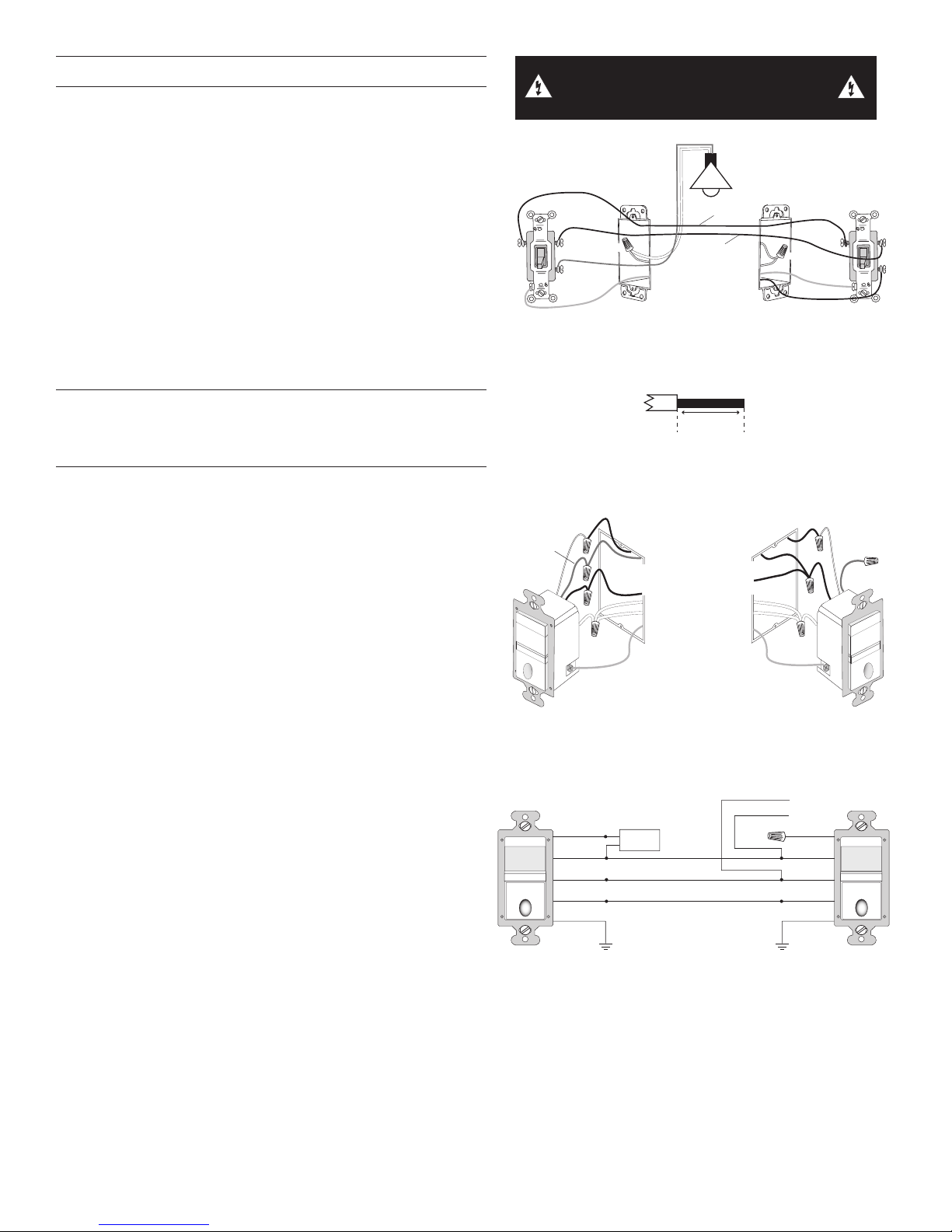
These instructions describe only the 3-way circuit applications. For
information about other applications, consult technical support.
1. Prepare the switch box.
After the power is turned OFF at the circuit breaker box, remove
the existing wall plate and mounting screws. Pull the old switch
out from the wall box.
2. Identify the type of circuit.
You may connect the CH-250 to a single pole or multi-way
circuit. If you are unable to clearly identify some or all of the
wires mentioned in this manual, you should consult with a
qualified electrician.
In a 3-way circuit (see Fig. 2), two traveler wires connect to
both switches. Another wire provides power from the circuit box
to one of the switches. A wire connects from one switch to the
load. A ground wire may also be connected to a ground terminal
on the old switches. A neutral wire should also be present in
both wall boxes.
WARNING: TURN THE POWER OFF AT THE
CIRCUIT BREAKER BEFORE WIRING.
Fig. 2: Typical 3-Way Switch Wiring
CAUTION: For your safety: Connecting a proper ground to the
sensor provides protection against electrical shock in the event of
certain fault conditions. If a proper ground is not available, consult
with a qualied electrician before continuing installation.
3. Prepare the Wires.
Tag the wires currently connected to the existing switch so that
they can be identified later. Disconnect the wires. Make sure
the insulation is stripped off of the wires to expose their copper
cores to the length indicated by the “Strip Gage,” in Fig. 3.
(approx. 1/2 inch).
4. Wire the sensor.
Twist the existing wires together with the wire leads on the
CH-250 sensor(s) as indicated in either figures 4a and 4b or
figures 5a and 5b. Cap wires securely using wire nuts.
Wiring two CH-250s in a 3-way configuration
• Connect the green or non-insulated (copper) GROUND wire
from the circuit to the green terminal on each CH-250.
• Connect the NEUTRAL wire from the circuit and from the
lamp (LOAD) to the white wire on the master CH-250.
• The term “master” designates the CH-250 that connects to
the load.
• Connect the NEUTRAL wire from the circuit in the other wiring
box to the white wire on the auxiliary CH-250.
• Connect the power wire from the circuit box (HOT) to the
black wire on the auxiliary CH-250 and to the TRAVELER 1
wire.
• Connect the TRAVELER 1 wire from the black wire of the
auxiliary CH-250 to the black wire of the master CH-250.
• Connect the lamp power (LOAD) to the red wire on the
master CH-250.
• Cap the red wire on the auxiliary CH-250.
• Connect the TRAVELER 2 wire coming from the yellow wire
of another CH-250 to the yellow wire of the CH-250 that you
are wiring.
TOP
INDOOR USE ONLY
MASTER CH-250
1/2"
Fig. 3: Wire Stripping
Fig. 4a: Sensor orientation, wire connections,
and wall box assembly
Hot
Neutral
Red
White
Black
Yellow
Ground
Load
Neutral
Traveler 1
Traveler 2
Red
White
Black
Yellow
Ground
AUXILIARY CH-250
Fig. 4b: Step 4a. Reference wiring diagram
TOP
INDOOR USE ONLY
2
Page 3

Wiring one CH-250 and one RH-253 single pole
Hot
Neutral
Time Delay
Adjustment
CH-250
TOP
INDOOR USE O NLY
Red -> LOAD
(power to lamp
or fan)
GROUND
TERMINAL
GROUND
TERMINAL
White ->
NEUTRAL
Yellow-> TRAVELER 2
to RH-253
TRAVELER 1
to CH-250
Black-> Traveler 1
power via RH-253
RH-253
HOT (power from
circuit box)
TRAVELER 2
to CH-250
momentary switch for multi-way Manual-ON/OFF
single load control.
IMPORTANT: The CH-250 must be installed in the wiring wall box
that connects to the load.
• Connect the green or non-insulated (copper) GROUND wire
in each wiring box to the green terminal on each CH-250 and
RH-253.
• Connect the NEUTRAL wire from the circuit and from the
lamp (LOAD) to the white wire on the CH-250.
• Connect the power wire from the circuit box (HOT) to one
terminal of the RH-253 single pole momentary wall switch and
to the TRAVELER 1 wire.
• Connect the TRAVELER 1 wire coming from the RH-253
wiring box to the black wire of the CH-250.
• Connect the lamp power (LOAD) to the red wire on the
CH-250.
• Connect the TRAVELER 2 wire to the other side of the
RH-253 single pole momentary wall switch and to the yellow
wire of the CH-250.
5. Put all the new switches into their wall boxes.
Position the CH-250 switch(es) with the lens above the ON/OFF
button (lens at top, ON/OFF button at bottom). Use the captive
screws on the mounting strap to secure the switches to their
wall boxes.
6. Restore power to the circuit.
Turn on the breaker or replace the fuse.
7. Make any necessary adjustments.
See the SENSOR ADJUSTMENT section for information.
8. Install cover plate.
Install industry standard decorator wall switch cover plate (not
included).
Fig. 5a: Sensor orientation and wire connections
for 3-way operation with an RH-253 momentary wall switch
To wire up to four RH-253 single pole momentary wall
switches to one CH-250, wire them in parallel as shown in
the following wiring diagram.
Red
TOP
INDOOR USE ONLY
CH-250
White
Black
Yellow
Ground
Load
Traveler 1 (Hot)
Traveler 2
Traveler 1
Traveler 2
Ground
Traveler 1
Traveler 2
Traveler 1
Traveler 2
Ground Ground
RH-253
To adjust the CH-250, you use a control located under the ON/OFF button. The wall switch cover plate must be removed to gain access
to the time delay adjustment dial under the ON/OFF button.
For multi-way operation, the Time Delay should be the same in all sensors related to the same load.
1. Firmly grasp the side edges of the Lock Bar and gently pull it away from the switch face until it
clicks. Do NOT attempt to pull the Lock Bar off of the switch!
2. Firmly grasp the side edges of the ON/OFF button. Slide the button downward approximately
1/2 inch to expose the adjustment dial.
Adjusting the Time Delay
Turn the dial counter-clockwise to reduce the amount of time the lights will remain ON after the last
motion detection (minimum = 15 seconds). Turn it clockwise to increase the time delay (maximum =
30 minutes). You can only select the following values: 15 seconds/5 minutes/15 minutes/30 minutes.
Warning: Do not overturn the Time Delay adjustment dial!
Fig. 5b: Reference wiring diagram for multi-way operation with
RH-253 momentary wall switches (4 maximum)
SENSOR ADJUSTMENT
3
RH-253
TOP
Lock Bar
15
Sec.
30
Min.
Suggested time delays
Bath or Ded room: 30: min.
Half or Stairway: 5-15 min
15
Min.5Min.
09560r1
INDOOR USE ONLY
Dial
Slide down
ON/OFF
Buttons
Fig. 6: Sensor Adjustment Control
RH-253
Page 4

TEST MODE
To test the detection coverage:
1. Press and hold the ON/OFF button.
After 10 seconds the lighted switch turns off. The load turns ON if it was not already ON. The sensor is now in a TEST mode that
lasts 5 minutes. (You can end the TEST mode sooner by pressing the ON/OFF button for another 10 seconds).
During the TEST mode, the controlled load turns ON for 5 seconds each time the sensor that initiated the TEST mode detects
occupancy.
2. Move out of the coverage area or stand very still. The controlled load turns OFF after 5 seconds if no motion is detected.
3. Move into the coverage area for the unit that initiated the TEST mode. The controlled load turns ON for 5 seconds each time
the sensor detects motion. After 5 seconds expire without motion detection, the load turns OFF. The controlled load turns ON
automatically with the next motion detection and stays ON for 5 seconds.
4. Repeat as necessary to ensure that the desired coverage areas are within detection range.
You can do this test for each CH-250 in your multi-way configuration. So that you can determine the actual coverage area for each multiway switch individually, only the CH-250 that is in TEST mode will control the load.
TROUBLESHOOTING
Lighted switch is OFF, no load response to ON/OFF button press:
• Make certain that the circuit breaker is ON and functioning.
Lighted switch is ON, no load response to ON/OFF button press:
• Check the lamp and/or motor switch on the fan mechanism.
Load will not turn OFF automatically:
• Press ON/OFF button. If the controlled load turns OFF, go to next step.
• The time delay can be set from 15 seconds to 30 minutes. Check the time delay setting for each CH-250 in your multi-way
configuration. Ensure that all CH-250s have the same time delay setting.
• Ensure that there is no movement within the coverage area for all the sensors related to the load for the set time delay. Hot air
currents and heat radiant devices can cause false detection. Make sure the sensor is at least 6 feet (2 meters) away from devices
that are a significant heat source (e.g., heater, heater vent, high wattage light bulb).
If load does not respond properly after following troubleshooting, turn OFF power to the circuit then check wire connections
or call technical support.
COVER PLATES
Wattstopper CH wall switches fit behind industry standard decorator style switch cover plates.
WARRANTY INFORMATION INFORMATIONS RELATIVES À LA GARANTIE INFORMACIÓN DE LA GARANTÍA
Wattstopper warranties its products to be free
of defects in materials and workmanship for a
period of five (5) years. There are no obligations
or liabilities on the part of Wattstopper for
consequential damages arising out of, or in
connection with, the use or performance of this
product or other indirect damages with respect
to loss of property, revenue or profit, or cost of
removal, installation or reinstallation.
Wattstopper garantit que ses produits sont
exempts de défauts de matériaux et de fabrication
pour une période de cinq (5) ans. Wattstopper
ne peut être tenu responsable de tout dommage
consécutif causé par ou lié à l’utilisation ou
à la performance de ce produit ou tout autre
dommage indirect lié à la perte de propriété, de
revenus, ou de profits, ou aux coûts d’enlèvement,
d’installation ou de réinstallation.
Wattstopper garantiza que sus productos
están libres de defectos en materiales y mano
de obra por un período de cinco (5) años. No
existen obligaciones ni responsabilidades por
parte de Wattstopper por daños consecuentes
que se deriven o estén relacionados con el
uso o el rendimiento de este producto u otros
daños indirectos con respecto a la pérdida
de propiedad, renta o ganancias, o al costo
de extracción, instalación o reinstalación.
No. 24554 – 09/16 rev. 1
© Copyright 2016 Legrand All Rights Reserved.
© Copyright 2016 Tous droits réservés Legrand.
© Copyright 2016 Legrand Todos los derechos reservados.
800.879.8585
www.legrand.us/wattstopper
 Loading...