

Page 1
CÉLIANE
™
Project and installation
Guide
CÉLIANE
Project and installation Guide
Release 01_10
Page 2

Page 3
IV CPL system
III SCS BUS system
II Radio system on ZigBee® technology
I Céliane introduction
CÉLIANE TECHNICAL GUIDE
Legrand SpA reserves at any time the right to modify the contents of this guide and to communicate, in any form and modality, the changes brought to the same.
Index of section
Page 4

CÉLIANE TECHNICAL GUIDE
I Céliane introduction
GENERAL FEATURES
- Creating value, solutions to enhance all your projects
- Two technologies
- Product technical scheets
II Radio system on ZigBee® technology
GENERAL FEATURES
- Radio ZigBee
®
- The possible functions
- The possible functions - existing plants
- The single functions
- Introduction to the Radio system on ZigBee® technology
- Product overview
- Controls
- Actuators: switches and dimmers
- Interfaces
GENERAL RULES FOR INSTALLATION
- Project approach
- Positioning of wall boxes
- Positioning of controls: practical installation examples
- Positioning of loads, users and layout of the ducts
- Distances and maximum number of devices
WIRING DIAGRAMS
CONFIGURATION
- The ZigBee
®
network
- Creating the ZigBee® network and associating the devices
- Associating the devices
- Disassociating devices
- Creating a scenario
RADIO SYSTEM ON ZIGBEE
®
TECHNOLOGY CATALOGUE
PRODUCT TECHNICAL SCHEETS
III SCS BUS system
GENERAL FEATURES
- SCS BUS
- The possible functions
- The single functions
- Integration of the functions
- Introduction to the SCS BUS technology
- Product overview
GENERAL RULES FOR INSTALLATION
- Project approach
- Positioning of the electrical distribution board
- Positioning of junction boxes
- Positioning of wall boxes
- Type of wiring
- Grouping cables in the same duct
- Selection table for the cables
- Layout of the ducts
- Positioning of controls: practical installation examples
- Basic configuration concepts
Page 5

Automation system
GENERAL FEATURES
- Introduction to the Automation system
- Control devices
- Actuators
- Interfaces
GENERAL RULES FOR INSTALLATION
- Maximun number of devices which can be configured
- Distances and maximum number of devices
WIRING DIAGRAMS
CONFIGURATION
- Basic configuration concepts
- Basic concepts for the configuration of actuators and controls
- Addressing levels
- Operation modes
Burglar alarm system
GENERAL FEATURES
- Introduction to the Burglar alarm system
- The devices
- Selection table for the devices
GENERAL RULES FOR INSTALLATION
- Project approach
- Distances and maximum number of devices
- Project example
- Installation of the devices
WIRING DIAGRAMS
CONFIGURATION
- Basic configuration concepts
Energy management system
GENERAL FEATURES
- Eco-energy home for energy control
WIRING DIAGRAMS
GENERAL FEATURES
- Introduction to the Temperature control system
- My Home Legrand thermoregulation system can be used:
- The advantages
- The guarantee of comfort and management
- A complete range
- Selection table for the devices
GENERAL RULES FOR INSTALLATION
- Distances and maximum number of devices
- Installation of the devices
- Legend of symbols
WIRING DIAGRAMS
GENERAL FEATURES
- Introduction to the display of consumptions
- The devices
- Selection table for the devices
Page 6

CÉLIANE TECHNICAL GUIDE
Sound system
GENERAL FEATURES
- Sound system 2 wire stereo HI-FI
- Wide range of solutions
- Installing a system
- Installation examples
GENERAL RULES FOR INSTALLATION
- Sound system wiring
- Max distances and cables features
- System consumption calculation
WIRING DIAGRAMS
CONFIGURATION
- Configuration requirement
- Basic configuration concept
Video door entry and home video surveillance system
GENERAL FEATURES
- Creating the system
- Simplicity of installation
- The devices
- Examples of installation
GENERAL RULES FOR INSTALLATION
- System functions
- System composition
- The configuration
- The wiring
- Installation of Entrance Panel, Handset and interfaces
- System maximum limits
- BUS consumption summary table
- BTicino items reference
WIRING DIAGRAMS
Integration and control
GENERAL FEATURES
- Integration and control introduction
- The integration
- Integration among several SCS systems
- Integration between My Home Legrand and external protocols
- Local control
- The local control devices
- Remote control
- The remote control devices
WIRING DIAGRAMS
SCS BUS SYSTEM CATALOGUE
PRODUCT TECHNICAL SCHEETS
Page 7

IV PLC system
GENERAL FEATURES
- Introduction to the PLC System
- The possible functions
- The devices
GENERAL RULES FOR INSTALLATION
- Installation of devices
- Features of the electric system
BASE PROGRAMMING CONCEPTS
- General features
- Configuration mode
AUTOMATION SYSTEM
- Management of lights and shutters
- Management of lights
- Management of blinds and shutters
- General features
TEMPERATURE CONTROL SYSTEM
- General features
- Devices for the temperature regulation
- Control and management devices
- Configuration
SPECIAL FUNCTIONS
- Scenario management
- Technical alarms
- System integration: interfaces
- Remote control of the functions
WIRING DIAGRAMS
PLC SYSTEM CATALOGUE
PRODUCT TECHNICAL SCHEETS
Page 8

CÉLIANE TECHNICAL GUIDECÉLIANE TECHNICAL GUIDE
Item Catalogue
Product technical sheets
026 02
026 11
026 21
026 22
026 31
035 51
035 52
035 53
035 60
035 62
035 65
035 67
035 73
035 79
035 80
035 83
035 84
035 85
035 86
035 87
036 00
036 03
036 06
036 07
036 08
036 09
036 10
036 11
036 12
036 18
036 48
036 52
036 53
036 56
038 09
038 41
038 42
038 44
492 31
492 32
5738 58
5738 60
5738 62
5738 64
5738 66
5738 70
5739 28
5739 30
Item Catalogue
Product technical sheets
5739 78
5739 81
5739 82
5739 83
5739 86
5739 88
5739 89
5739 92
5739 93
5739 94
5739 96
5739 98
5739 99
5740 44
633 01
633 31
633 40
633 41
633 42
633 44
633 46
633 48
633 50
633 52
633 56
633 70
633 71
633 72
633 74
633 76
633 78
634 00
634 31
634 32
634 33
634 34
634 35
634 36
634 38
634 39
634 41
634 42
663 71
663 72
663 73
663 74
663 80
663 81
Index
progressive of items
Page 9
Item Catalogue
Product technical sheets
663 82
663 83
663 84
663 90
663 91
663 92
663 93
663 94
672 01
672 02
672 03
672 04
672 08
672 09
672 10
672 12
672 14
672 15
672 16
672 17
672 18
672 31
672 33
672 34
672 35
672 36
672 37
672 39
672 40
672 41
672 42
672 43
672 44
672 45
672 46
672 47
672 48
672 51
672 53
672 54
672 55
672 56
672 63
672 64
672 80
672 81
672 82
672 83
Item Catalogue
Product technical sheets
672 84
672 85
673 01
673 02
673 03
673 04
674 40
674 42
674 45
674 48
674 49
674 51
674 55
674 56
674 57
674 58
675 02
675 03
675 04
675 05
675 06
675 07
675 08
675 11
675 12
675 13
675 15
675 20
675 22
675 23
675 24
675 25
675 46
675 47
675 48
675 50
844 24
882 00
882 01
882 02
882 03
882 12
882 13
882 20
882 21
882 23
882 32
Page 10

Céliane introduction
CÉLIANE TECHNICAL GUIDE
Céliane introduCtion
Page 11

Céliane introduction
General features.......................... 00
>
Page 12
I-10I-10
CÉLIANE INTRODUCTION
GENERAL FEATURES
MY HOME Legrand, the comprehensive and versatile home automation solution, which is
integrated to Céliane line satisfies your most demanding customer’s needs.
MY HOME Legrand is the answer for any kind of home automation requirement: from a single
function like automation or independent different functions to completely networked integrated
solutions.
Creating value, solutions
to enhance all your projects
I-10
All load dimmer
(ZigBee®)
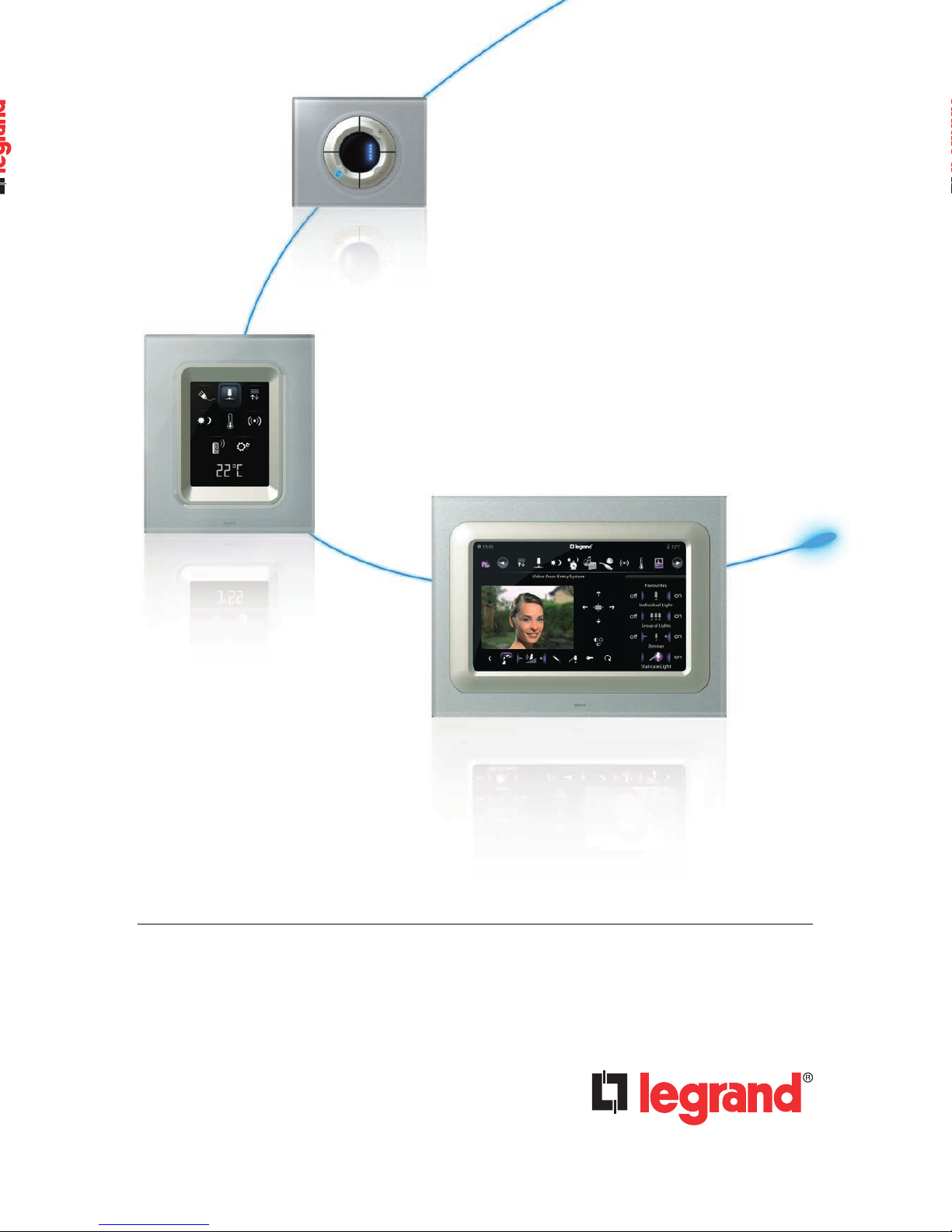
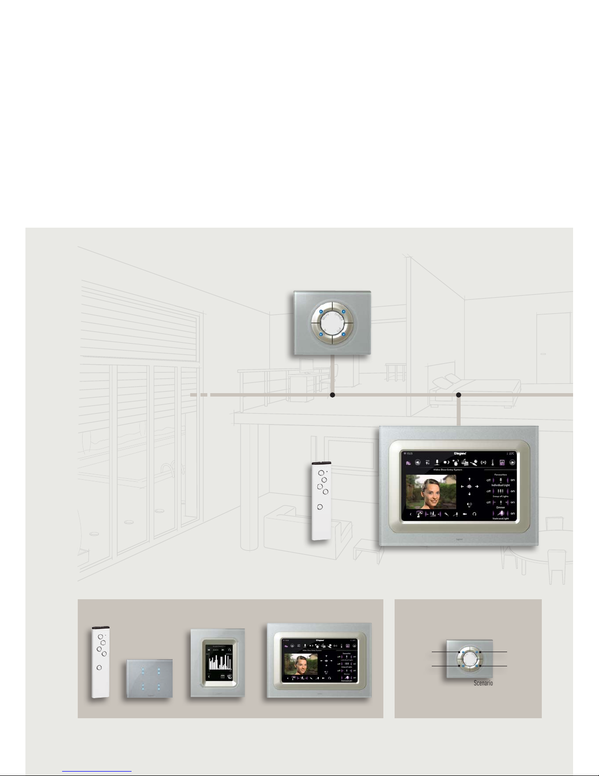
Multimedia Touch Screen
One only touch screen can replace a lot of control products: the dashboard of your Home!
Video door entry system and control centre for home control scenarios, video door entry and video
surveillance functions via a 10" control screen linked to indoor and outdoor cameras.
Distribution of multimedia contents (web, video, music, etc.)
4-scenarios micro push control
(SCS BUS)
4-scenarios Touch Control
(SCS BUS)
Page 13
I-11
CÉLIANE TECHNICAL GUIDE
Céliane introduCtion
I-11
Céliane introduCtion
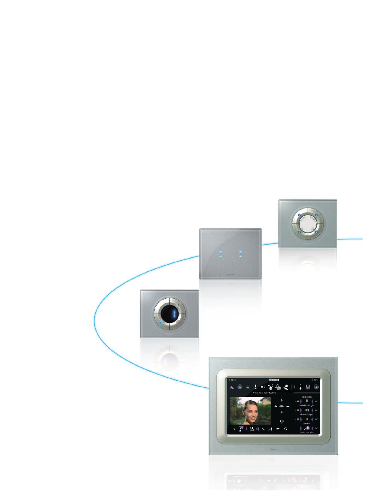
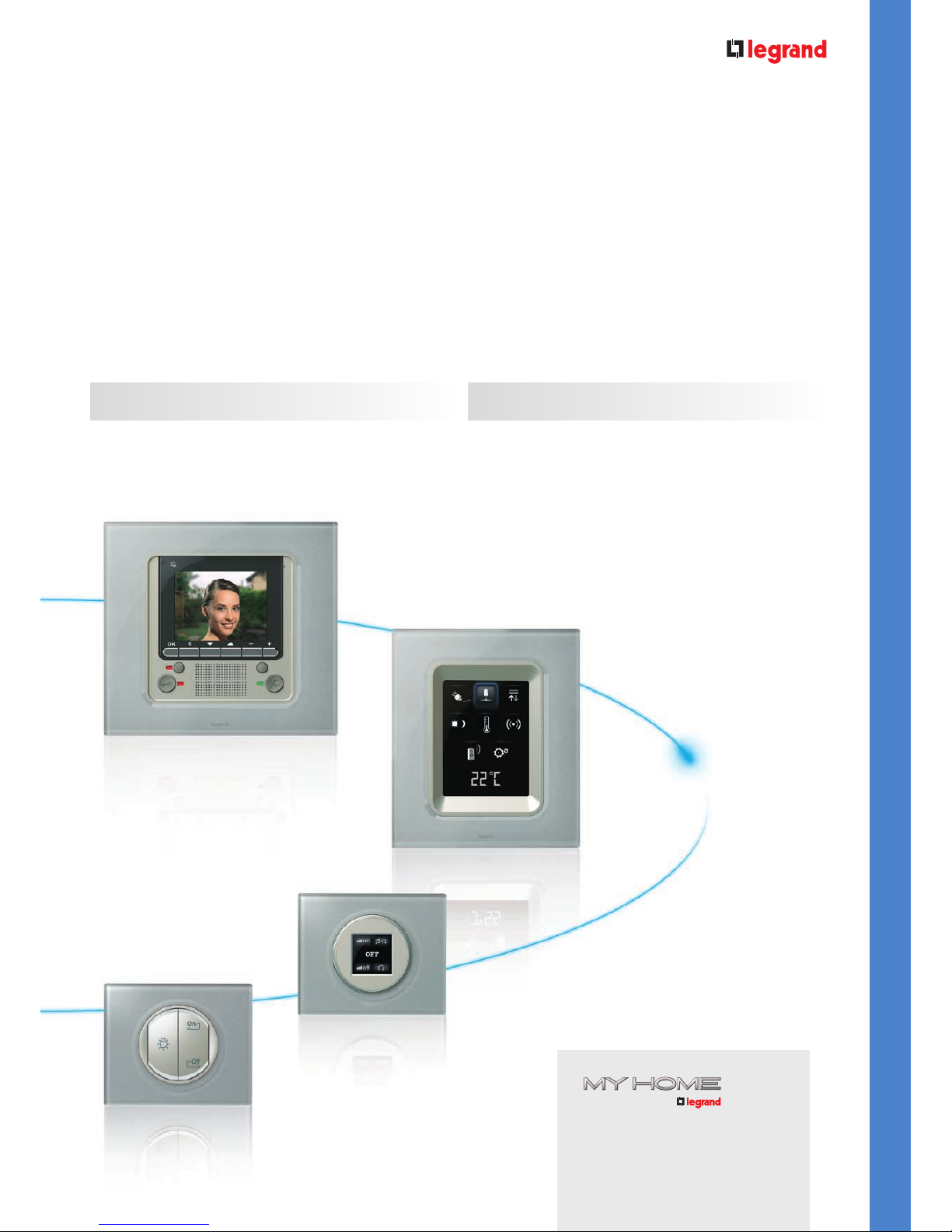
The system works on two different media:
Products have been developed to ensure perfect interoperability and maximum reliability of the
system. MY HOME Legrand installations can easily be modified and extended at any time.
RADIO TECHNOLOGY USING ZIGBEE
®
PROTOCOL
BUS TECHNOLOGY USING SCS PROTOCOL
Video display
Identify visitors in colour on the screen, talk hands free,
open the door with a single action.
3,5 " Touch screen
Control centre. Manage the scenarios for every room: lighting,
shutters, sound system, temperature regulation, alarm system.
Local Display
1,2" touch screen in «sound distribution» mode
SCS BUS Basic control
The answer for all home automation
requirements, from a single function
to global integrated solutions.
My Home Legrand supports 2 technologies:
Radio using ZigBee® protocol and BUS
using SCS protocol.
Page 14
I-12I-12
CÉLIANE INTRODUCTION
GENERAL FEATURES
Two technologies
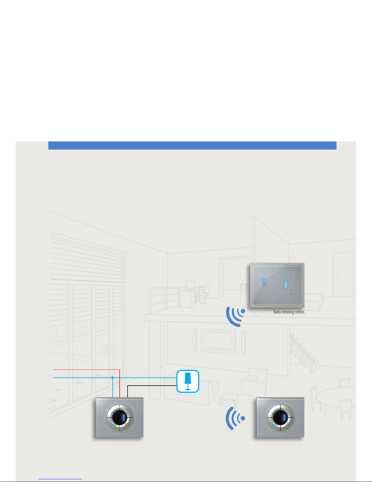
The standard in (wireless) radio solutions for renovation work and new-build. Multiplies the number of control points, without
damaging the walls.
At a frequency of 2.4 GHz, using transmitters (wireless) and receivers, this can control lighting, shutters and also technical
alarms. It can be used to control scenarios and offers the option of reverting back due to the two-way communication between
devices. Can be used to complement the BUS system.
RADIO ZIGBEE
®
L
N
Radio dimmer Radio dimming control
Radio dimming control
with Touch plate
Page 15
I-13
CÉLIANE TECHNICAL GUIDE
Céliane introduCtion
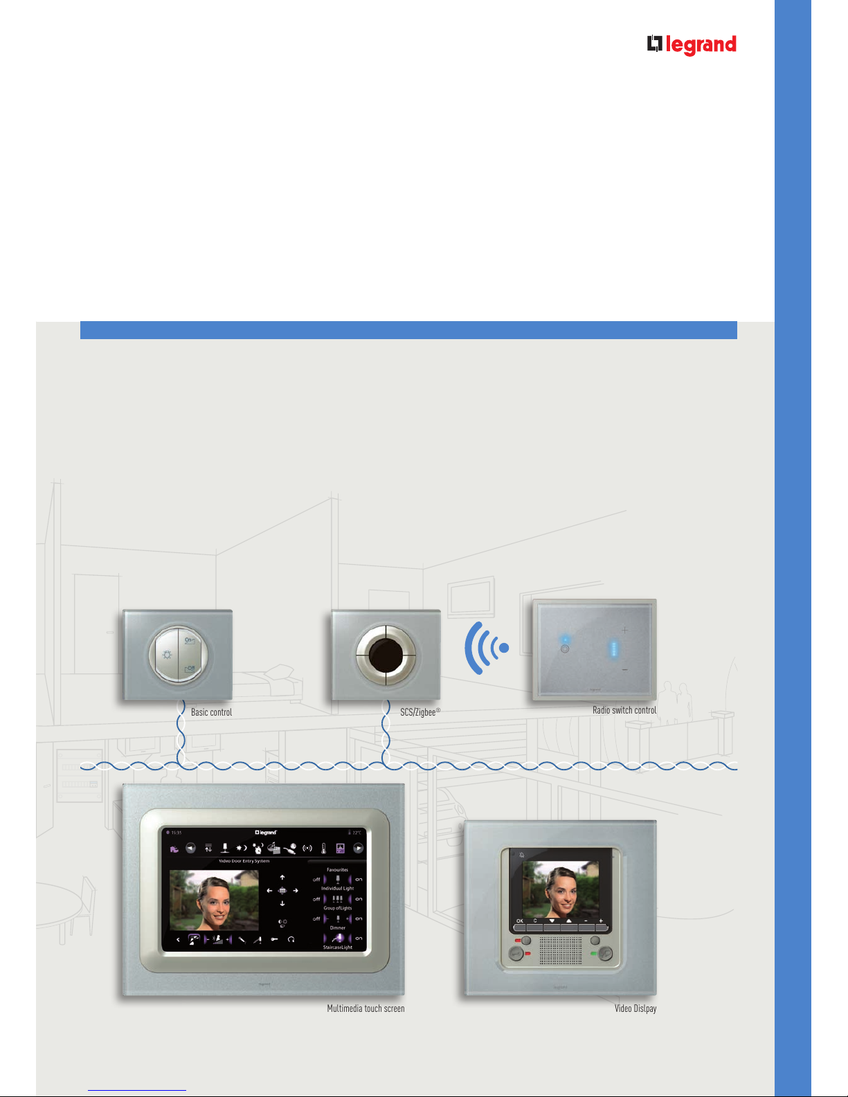
Quick distribution and multiplication of a maximum number of functions where there is no restriction on space.
SCS BUS technology can be used to manage all functions simultaneously with a programmable electronic circuit. All the
devices are power supplied and exchange the data through 2-wire extra-low voltage cables (27V).
This enables simultaneous management of a number of functions (scenarios): energy efficient, security, multimedia and
comfort. Multi-interfaces choice for the user. Possible interfacing with Radio ZigBee
®
1.
SCS BUS
Multimedia touch screen
Basic control
Video Dislpay
Radio switch control
with Touch plate
SCS/Zigbee
®
gateway
Automation SCS BUS
Page 16
I-14I-14
CÉLIANE INTRODUCTION
GENERAL FEATURES
Two Technologies
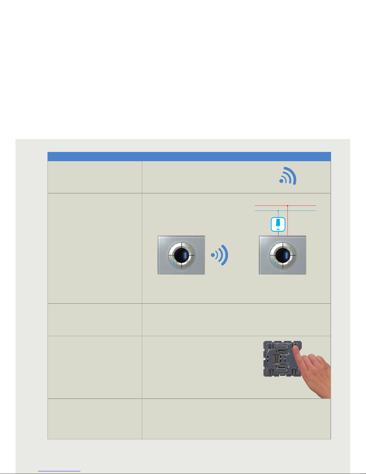
FEATURES
RADIO ZIGBEE® TECHNOLOGY
TECHNOLOGY:
Radio based on ZigBee® protocol use 2,4 GHz frequency and
doesn’t require any special wiring using existing electrical
infrastructure of a building.
TYPE OF DEVICES:
ZigBee® devices can be divided into 2 types:
Command transmitting devices (Battery powered)
Receiving devices (switch and dimmers actuators) connected
to the power cable for load management.
FUNCTIONS:
- Shutters and light automation
- Technical alarm (detection of gas and water)
- Scenarios
CONFIGURATION OF THE DEVICES:
Directly on the product with Push and Learn procedure.
WHEN TO USE IT?
- for less complex, new installations;
- to make traditional electrical installation evolve into a home automation system;
- when an extension is needed on an existing home automation system (e.g. to add a control point to an existing installation);
- if it is not possible to make changes on the traditional electrical installation and no recabling is allowed (e.g. renovation).
L
N
Page 17
I-15
CÉLIANE TECHNICAL GUIDE
Céliane introduCtion
FEATURES
SCS BUS TECHNOLOGY
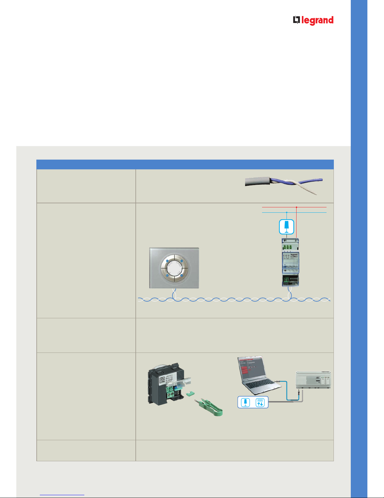
TECHNOLOGY:
The devices are connected in parallel with a non polarized
twisted-pair cable for sending information and with low
voltage (27V dc) electrical power.
Twisted-pair BUS cable
TYPE OF DEVICES:
Command devices connected to the BUS cable
Actuators connected to the BUS cable and also to the power
cable for load management.
FUNCTIONS:
- Shutters and light automation
- Scenarios
- Burglar alarm
- Technical alarm (detection of gas and water)
- Energy management
- Sound management
- Video door and home video monitoring
- Indoor and outdoor control of integrated functions
- Expansion opportunities with ZigBee devices
- Integration with Konnex protocol based systems.
CONFIGURATION OF THE DEVICES:
Simplified configuration with jumpers which can used to
configure presets or actions which can be identified on each
accessory
Configuration through a special software (virtual configurator)
that enables to configure off-line the system (lighting and
shutters automation).
WHEN TO USE IT?
- especially suitable for new installations in medium and large building;
- To create fully networked solutions by integration different applications from comfort, safety or energy saving functions up
to door entry systems, management of multimedia contents or remote supervision and control.
L
N
SCS BUS
Automation system
SCS BUS
Page 18
I-16I-16
CÉLIANE INTRODUCTION
GENERAL FEATURES
The following pages contain all the technical information needed for assessing, designing, and
installing a MY HOME Legrand home automation system. For more detailed information on the
individual devices, please refer to the corresponding Product Technical Sheets. These can be found
using the item code no.
For each device, the Product Technical Sheet lists the following information:
• Product description;
• Correlated items;
• Technical and size information;
• Configuration;
• Electric diagram, if applicable.
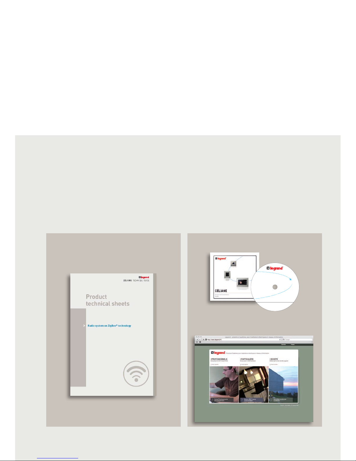
2. They are also available inside the attached CD, listed by
item code no.
3. They are also available on the internet, by visiting
the "Professionnelles" section of the
www.legrand.fr website
Product
technical sheets
1. "Product Technical Sheet" chapter at the end of the
three sections of the guide:
• Radio ZigBee
®
;
• SCS BUS;
• PLC system.
The Product Technical Sheets can be accessed in one of the following three ways:
CÉLIANE
Project and installation
Guide
Contents of CD-ROM
●PDF
Project and installation
Guide 2010
●PDF Portfolio
Product technical sheets
CD cover
Page 19
I-17
CÉLIANE TECHNICAL GUIDE
Céliane introduCtion
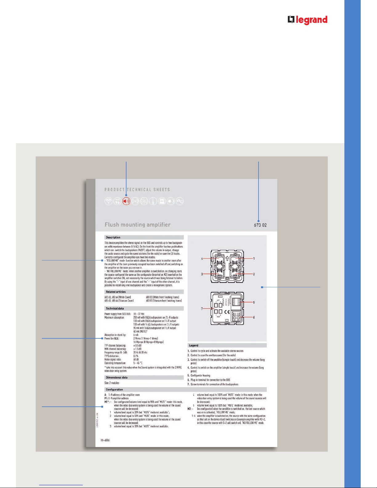
Icon of the system the item belongs to,
e.g.: Sound Diffusion
Device item
code No.
Device
description
Drawing with device
description
Technical
specifications
Configuration
Page 20

SCS BUS system
CÉLIANE TECHNICAL GUIDE
sCs Bus system
Page 21
SCS BUS system
General features ......................... 000
General rules for installation...... 000
Automation system ............ 000
Burglar alarm system ....... 000
Energy management system
000
Sound system ..................... 000
Video door entry and home
video surveillance system ... 000
Integration and control ....... 000
SCS BUS system catalogue ........ 000
Products technical sheets .......... 000
>
Page 22
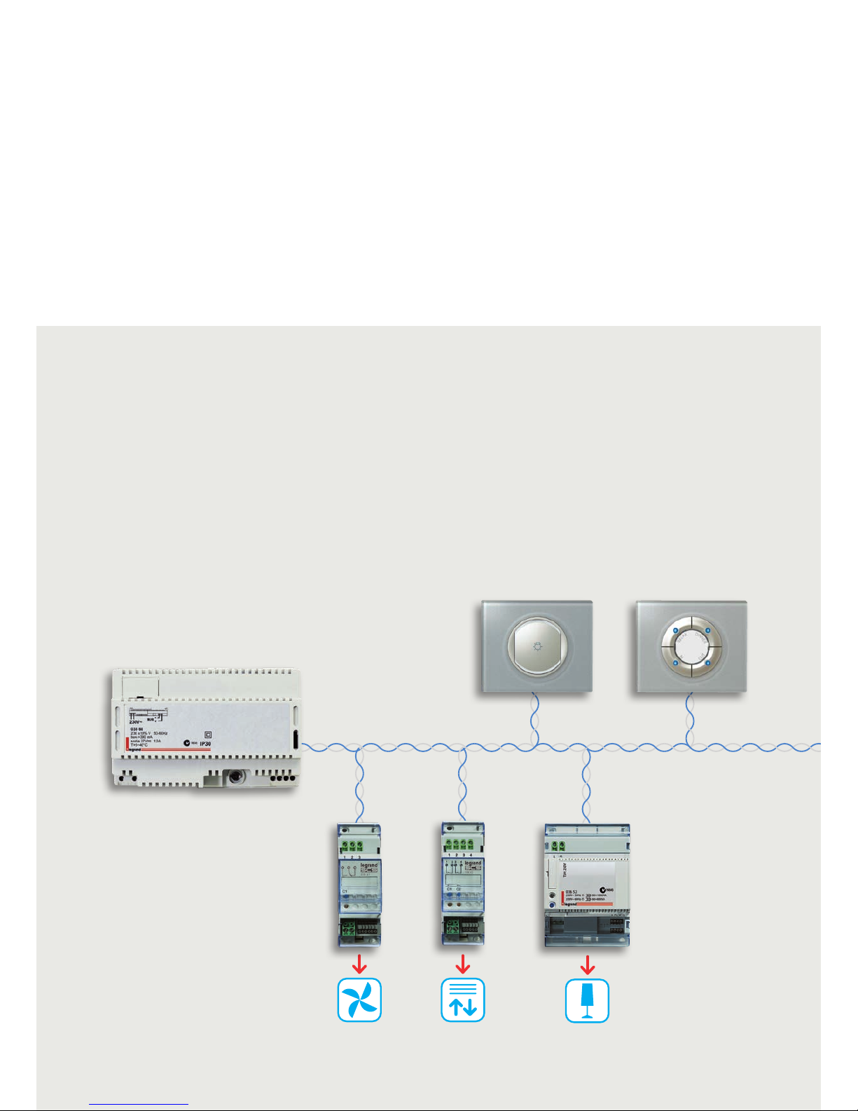
SCS BUS SYSTEM
GENERAL FEATURES
III-64III-64
SCS BUS
BUS CONTROLS
DIN ACTUATORS
Power supply
Basic control 4 scenario control
1 relay DIN
actuator 16 A
2 relays DIN
actuator 10 A
DIN dimmer
1000 W
The BUS system can be used to perform various home
automation functions for:
• ENERGY CONTROL;
• SAFETY;
• COMMUNICATION;
• COMFORT.
COMPLETE HOME AUTOMATION SOLUTIONS CHARACTERISTICS
The BUS systems, intended for new large installations, are made
using a twisted pair, which connects the command and control
devices to the actuators. The control devices are installed inside
appropriate wall boxes. The actuators are installed inside the
electric distribution board, junction boxes, or in direct proximity
of the load. Control devices must be connected to the SCS BUS
and to power cable for load managed.
Page 23
CÉLIANE TECHNICAL GUIDE
SCS BUS SYSTEM
III-65
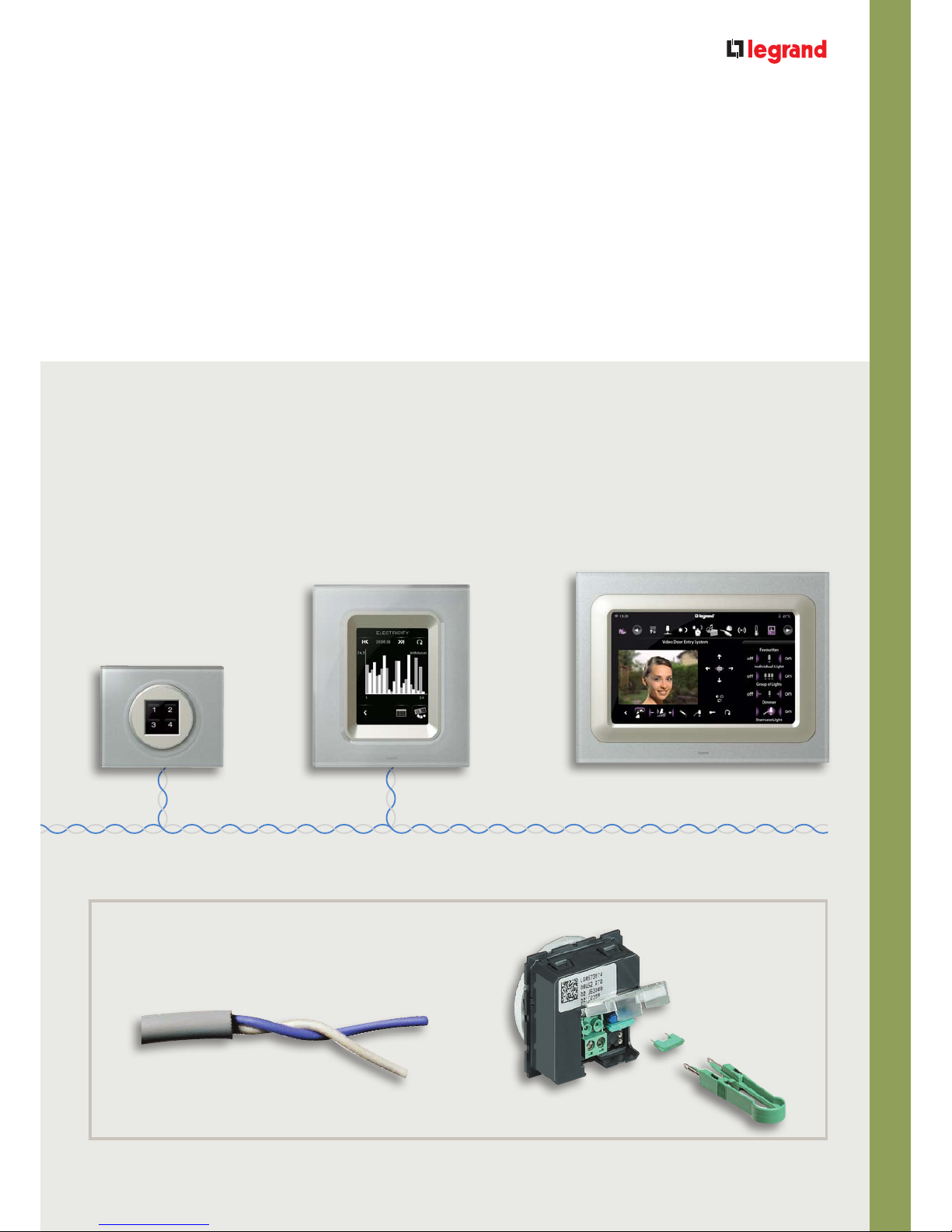
TOUCH SCREEN CONTROLS
ConfigurationBUS cable
Local Display
Touch Screen
Multimedia Touch screen
The association between control and actuator is ensured by
the configuration: the configuration allocates a unique address
to the control device and the actuator in communication with
each other. The BUS system is therefore very versatile: with a
simple change in the configuration it is possible to change the
association between the control device and the actuator. It is also
very safe, power supply does not reach the control boxes.
CONFIGURATION OF THE FUNCTIONS VERSATILITY
The versatility of the BUS system means that with just a few
operations, it is possible to change the control points to meet the
needs of the customer even after the system has been completely
installed, and without the need for opening junction boxes or
installing further cables.
SCS BUS
Page 24
SCS BUS SYSTEM
GENERAL FEATURES
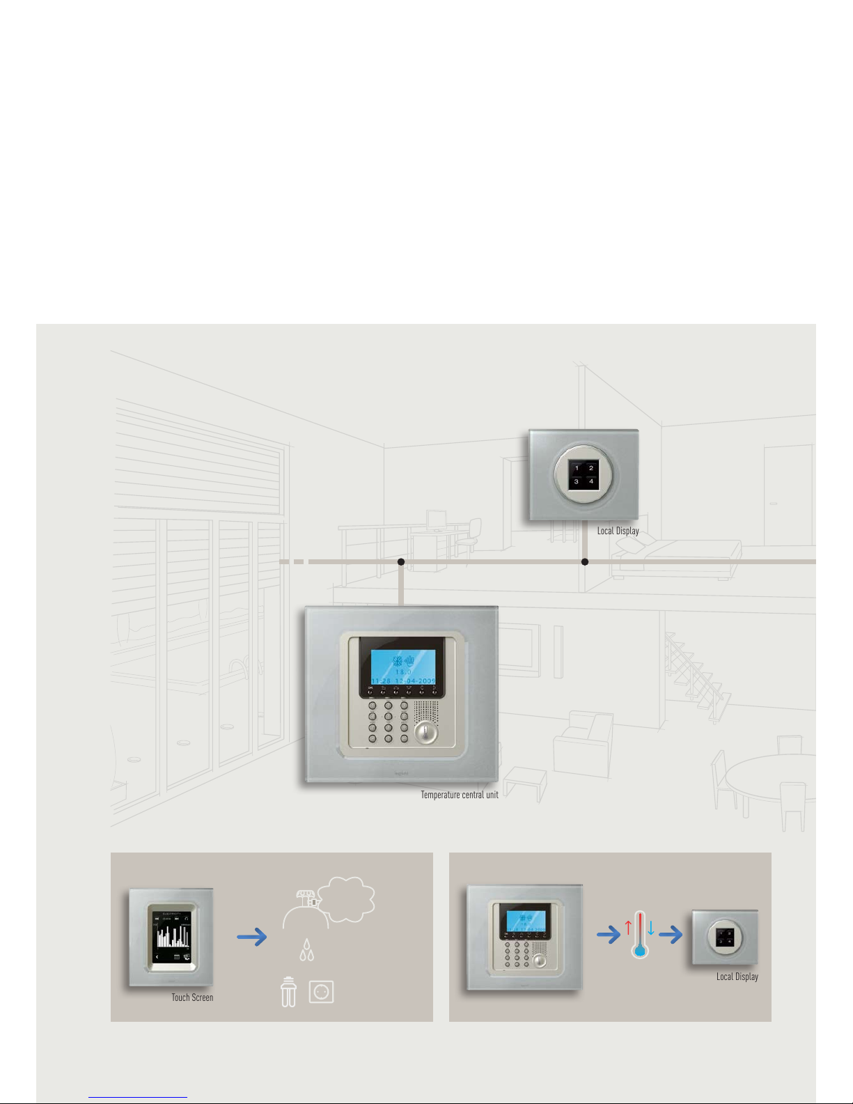
III-66III-66
The possible
functions
Complete solutions for controlling and managing energy.
ENERGY-EFFICIENT
Local Display
Touch Screen
Temperature central unit
Display of consumption
m3/€
m
3
/€
KWh/€
Temperature central unit
Local Display
Room-by-room temperature control
Page 25
CÉLIANE TECHNICAL GUIDE
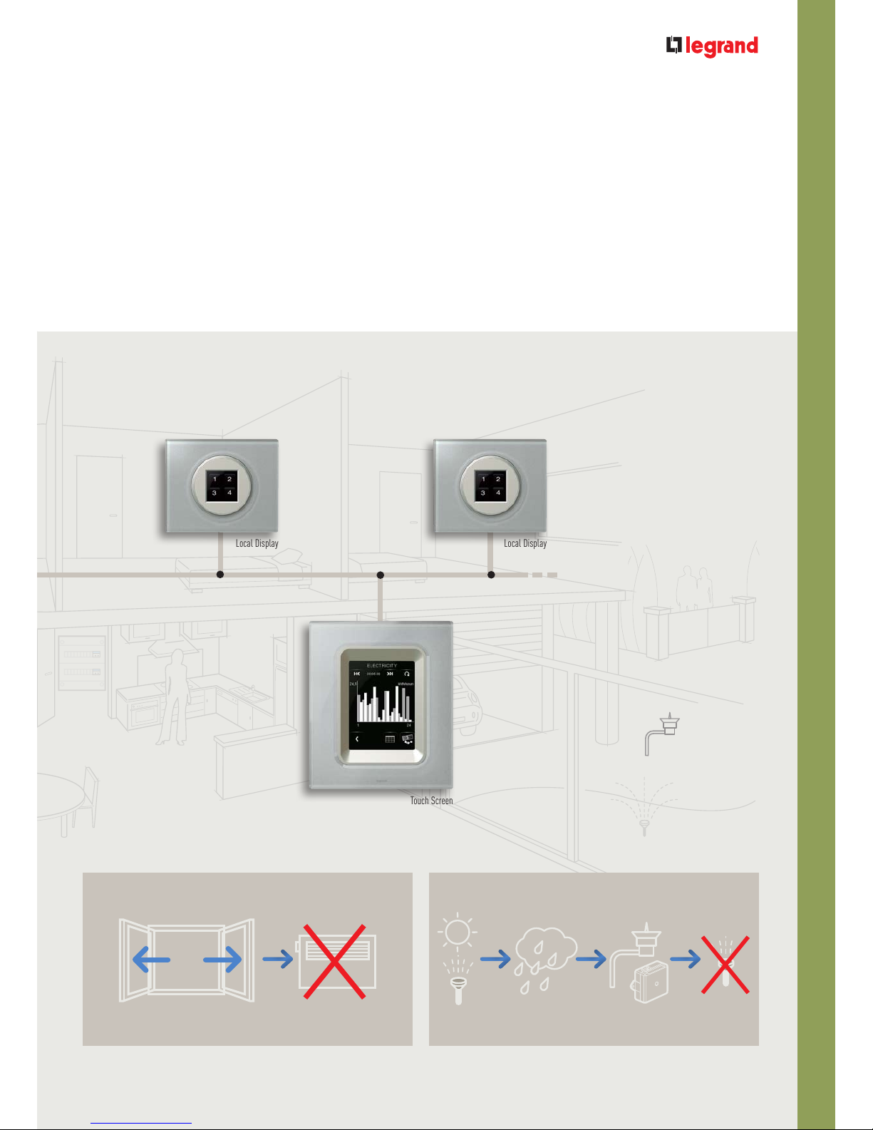
SCS BUS SYSTEM
III-67
Local Display Local Display
Touch Screen
Automatic switching off of heating when windows are
opened
Irrigation management
Sensor
Page 26
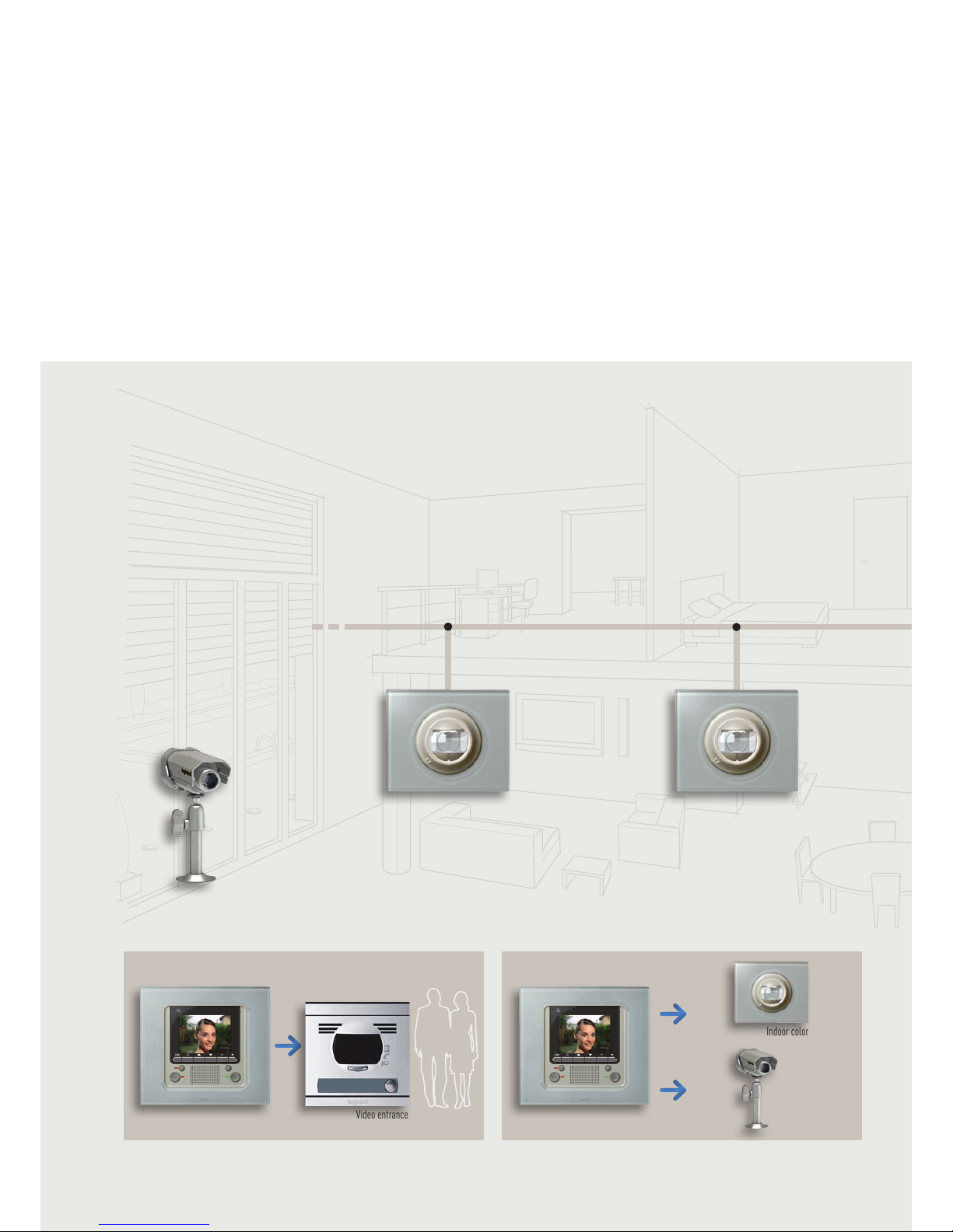
SCS BUS SYSTEM
GENERAL FEATURES
III-68III-68
The possible
functions
Complete solutions for controlling and providing security.
SECURITY
Indoor color
camera
Indoor color
camera
Indoor color
camera
Greet visitors View wh at’s going on
Video Display
handset
Video Display
handset
Video entrance
panel
Outdoor color
camera
Outdoor
color camera
Page 27
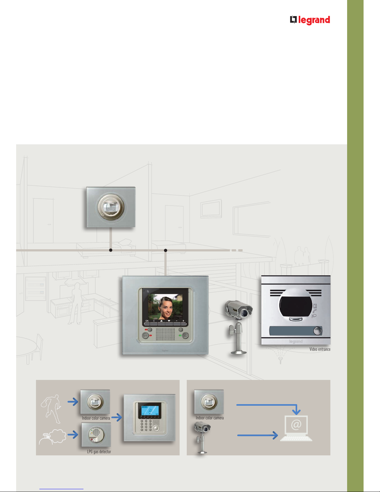
CÉLIANE TECHNICAL GUIDE
SCS BUS SYSTEM
III-69
Video Display
handset
Video entrance
panel
Indoor color camera
Indoor color camera
PC or Mobile phone
LPG gas detector
Intruder detection Remote surveillance
Burglar alarm
central unit
Indoor color
camera
Outdoor color
camera
Outdoor
color camera
Page 28
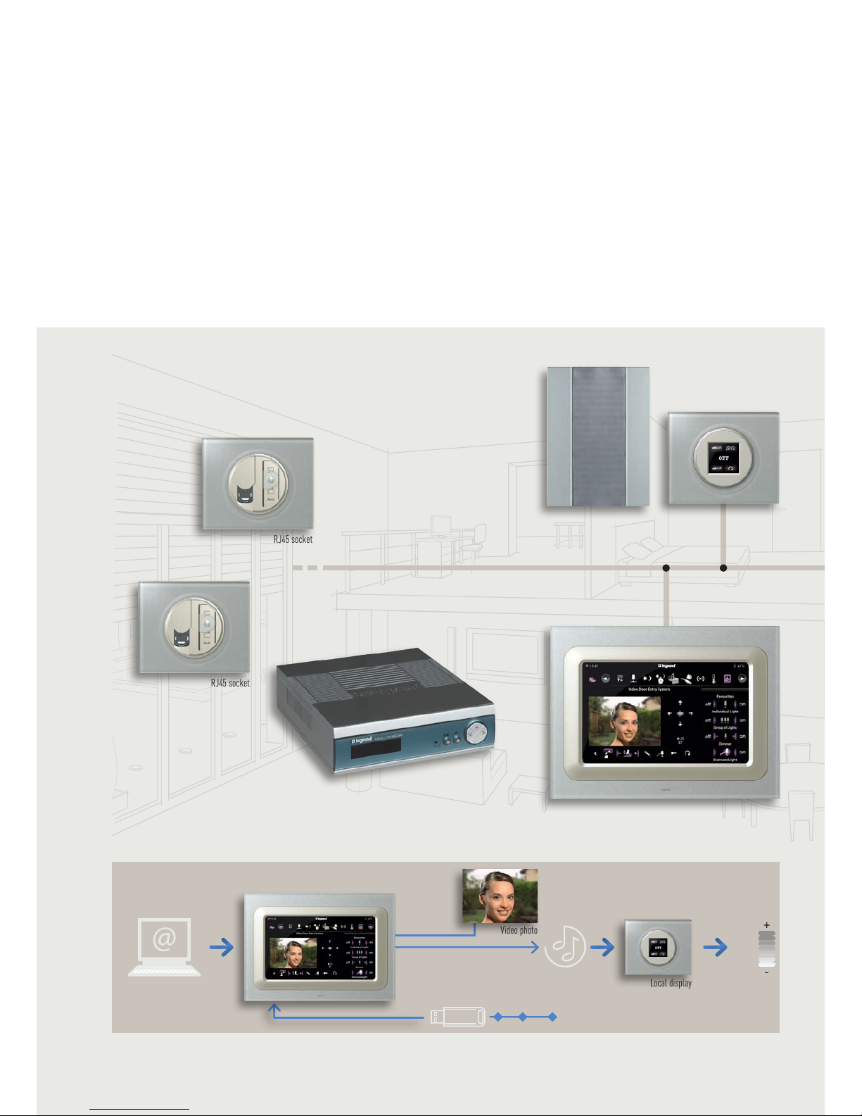
SCS BUS SYSTEM
GENERAL FEATURES
III-70III-70
The possible
functions
Media streaming
Complete solutions for managing and streaming media.
COMMUNICATION
Play list
photo video
MP3 PHOTO VIDEO
Video photo
100%
30%
60%
Multimedia
interface
RJ45 socket
RJ45 socket
Flush mounting
loudspeaker
Play list
photo video
Local display
Multimedia Touch screen
Local display
Multimedia Touch screen
Page 29
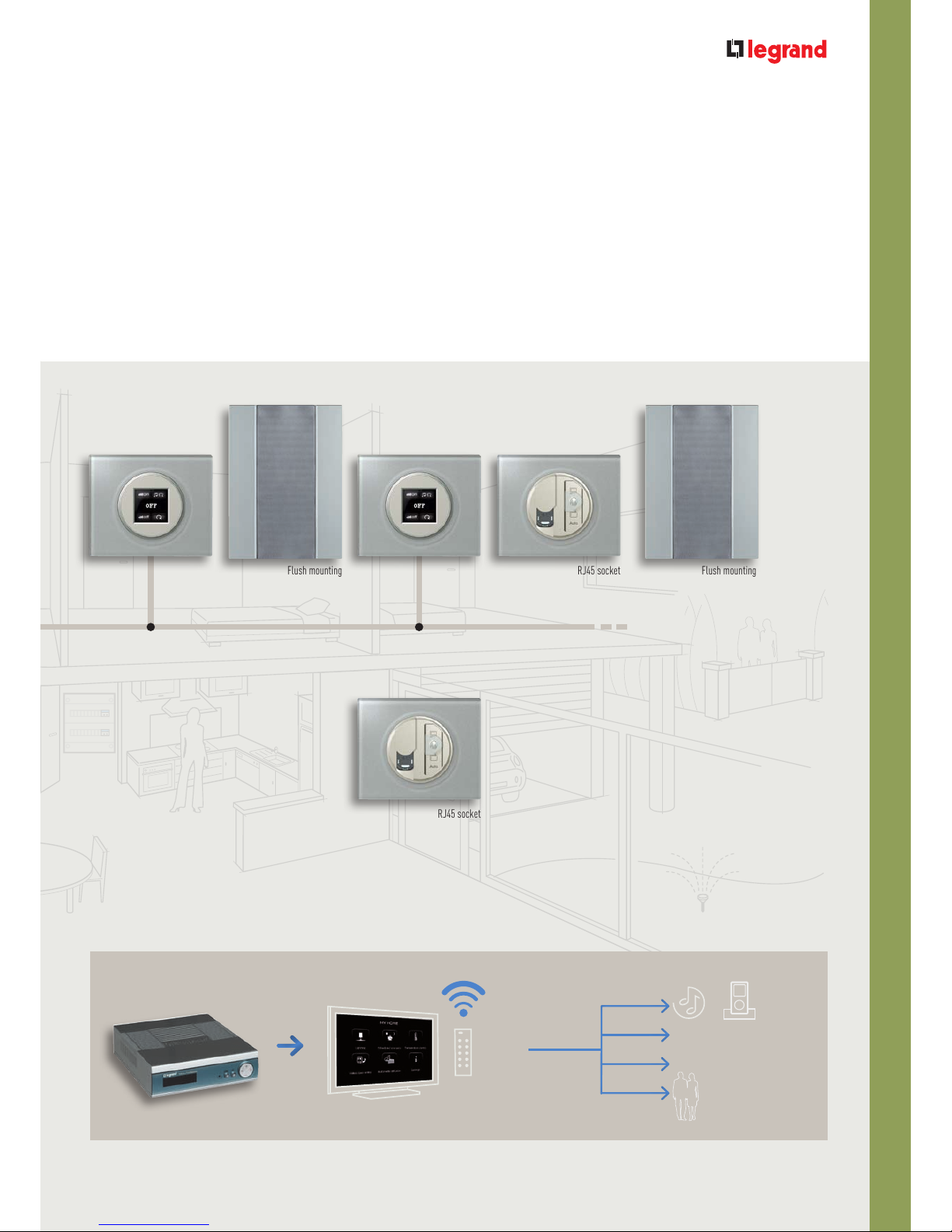
CÉLIANE TECHNICAL GUIDE
SCS BUS SYSTEM
III-71
Media streaming and management. Greeting visitors
Flush mounting
loudspeaker
Flush mounting
loudspeaker
Local display Local display
TV
VIDEO, DVD
Multimedia
interface
RJ45 socket
RJ45 socket
Page 30
SCS BUS SYSTEM
GENERAL FEATURES
III-72III-72
The possible
functions
Zone management for energy-efficient, with full security, multimedia, and
full comfort house. Multi-interfaces choice.
Complete solutions for making scenarios and managing: lighting, shutters, temperature, music…
COMFORT
Touch control
multifunction
Touch Screen
Scenario
control
Remote control
Scenario
control
swimming
pool
home
theater
relax
dimmer
Multimedia Touch screen
Multimedia Touch screen
Remote
control
Page 31

CÉLIANE TECHNICAL GUIDE
SCS BUS SYSTEM
III-73
Control of the system from a mobile phone using the Open WebNet protocol
Web server WI-FI Smartphone, iPhone
Scenario
control
Touch Screen
Page 32

SCS BUS SYSTEM
GENERAL FEATURES
III-74III-74
The single
functions
The automation system is used to control lights, rolling shutters, swing
doors and irrigation, etc. in a simple and logic way.
Light Control Rolling shutter control
AUTOMATION SYSTEM
Thanks to the automation system, scenarios can be created
and controlled.
Using the scenarios, one single pushbutton can be used to
control several devices (lights, rolling shutters) within the
automation system, and to control the other systems.
With the automation system, devices can also be controlled
using the remote control.
The system may also be interfaced with the ZigBee® radio
system, or with other traditional controls.
IR receiver
Advanced IR and RF
remote control
SCS/Zigbee®
gateway
Radio switch control
SCS BUS
Page 33

CÉLIANE TECHNICAL GUIDE
SCS BUS SYSTEM
III-75
The burglar alarm system provides protection of the home without
compromising on design. The system may be divided into zones, so
that the best way to protect the home may be achieved (perimeter, IR
sensors, double technology...)
BURGLAR ALARM SYSTEM
Burglar alarm central
unit with communicator
IR detector
Indoor siren
Basic contact
interface
Energy management is a complete system for control and display of the
energy consumptions (water, electricity and gas) levels of the home.With
the temperature control system, it is possible to create a centralised
management system divided into zones: each room is fitted with a
temperature sensor, to ensure maximum comfort and maximum savings.
Temperature
central unit
ENERGY MANAGEMENT
Probe with
regulation
20 + 1 °C
Radiator ON
Outdoor siren
SCS BUS
SCS BUS
Touch Screen
Page 34

SCS BUS SYSTEM
GENERAL FEATURES
III-76III-76
Video door entry and home video door surveillance provides interaction
with visitors calling from the entrance panels, as well as supervision of
any common and private areas of the building.
Video entrance panel
Outdoor color
camera
VIDEO DOOR ENTRY AND HOME VIDEO SURVEILLANCE
With the sound system, it is possible to set-up inside the home
a single or multichannel audio system, with centralised sound
sources. Amplifiers and loudspeakers can be integrated in the home
environment, in a discrete and elegant way.
SOUND SYSTEM
DIN radio
Flush mounting
amplifier
Flush mounting loudspeaker
The single
functions
Video Display
Page 35

CÉLIANE TECHNICAL GUIDE
SCS BUS SYSTEM
III-77
The functions of My Home Legrand may be integrated, ensuring
interaction and expansion of the functions within the home. System
integration also provides centralised supervision and control of the
functions from the individual devices:
Touch Screen, Multimedia Touch Screen, Video Display and software
Visual.
CONTROL AND INTEGRATION
The integration of the functions also gives the possibility to display the
images recorded by the camera following an alarm, switch the lights on
when the burglar alarm is disarmed, or automatic lowering the sound
system volume when a call is received on the video handset.
Pc with software Visual
Integration
of the functions
Video Display
Multimedia Touch Screen
Touch Screen
Page 36

SCS BUS SYSTEM
GENERAL FEATURES
III-78III-78
Introduction to the SCS BUS
technology
These are control and management devices connected to
the BUS, for the electric power supply and exchange of
information.
Besides connection to the BUS cable, these devices are also
connected to the electric power line (phase conductor), for
the management of the load.
CONTROL DEVICES
ACTUATOR CONNECTED TO THE LOAD
Inside the SCS BUS system there are two type of devices:
• Control only devices;
• Actuator connected to the load.
screw plug-in terminal
BUS cable
Electric power line
Actuator
BUS cable
Page 37

CÉLIANE TECHNICAL GUIDE
SCS BUS SYSTEM
III-79
COMPOSITION OF THE DEVICES
Flush-mounting box
Small frame Electronic devices to be finished
with front cover key
Eg. base control, advanced
control, amplifier...
1 module underkeys 1 module front cover keys Cover plate
1 function 2 functions 1 or 2 functions
2 module underkeys 2 module front cover keys
1 function 2 functions 1 or 2 functions
Electronic devices in white or
titanium colour e.g. probes,
IR, Local Display, RCA Input,
Connectors...
Touch control
Flush-mounting box Video Display, Touch Screen,
Control units…
Cover plate
Page 38

SCS BUS SYSTEM
GENERAL FEATURES
III-80III-80
Product overview
CONTROLS
TOUCH CONTROLS
REMOTE CONTROL
IR receiver
White Titanium
GraphiteKaolin
Titanium
Advanced IR and RF
remote control
(Battery Supplies)
Control already fitted with electronic parts.
MICROPUSH, TOUCH AND REMOTE CONTROL
Control to be fitted with key base, finishing key covers, frame
and cover plate.
Page 39

CÉLIANE TECHNICAL GUIDE
SCS BUS SYSTEM
III-81
VIDEO DISPLAY
TOUCH SCREEN CONTROL
The device is not a Touch Screen device.
Video Display 2,5”
The devices must be fitted with cover plate.
The devices must be fitted with surround
plate.
1 relay DIN
actuator 16 A
2 relays DIN
actuator 10 A for shutter
DIN
dimmer
Local Display 1,2” Touch Screen 3,5” Multimedia Touch Screen 10”
TOUCH SCREENS AND VIDEO DISPLAY
DIN MODULES DEVICES
Page 40

SCS BUS SYSTEM
GENERAL RULES FOR INSTALLATION
III-82
When completing a My Home Legrand project, a careful
assessment of the following is of fundamental importance:
• Choose the functions;
• Analysis of the system to be completed, selecting between SCS
BUS and ZigBee
®
radio system integration;
• System layout.
Irrespective of the type of system and the required house
automation applications, it is necessary that the layout of the
house is made available to the installer. It is also important
that a check is carried out, to ensure that the initial project
requirements are in line with the actual site: number of rooms
and their use (living room, bedroom, bathroom etc.)
Project approach
On a design and installation point of view, the installation of a house automation system is not much different from that of a traditional
electric power system, particularly in terms of:
• The positioning of the electric distribution board;
• The positioning of the junction boxes;
• The positioning of wall boxes;
• The definition and positioning of loads and users.
• The layout of the ducts;
• The type of wiring;
• The coexistence of cables inside the same duct.
Page 41

CÉLIANE TECHNICAL GUIDE
SCS BUS SYSTEM
III-83
• Maximum distance between connections
In completing the system, take into account the maximum
length of the extended cable and the maximum distance
between the components.
• The maximum number of devices that can be connected
Depending on their total absorption and on the distances
between the connection point and the power supply.
• Functions of the devices
By configuring the devices, it will be possible to define their
function within the system.
1
10
10
1
1
1
1
1
1
10
1
1
1
1
1
10
SL
When installing house automation systems, some specific elements must however also be considered:
The following pages will provide some suggestions and practical recommendations on the above points.
Pushbutton control – 1
load - special functions -
2 modules
Flush-mounted dimmer
actuator – 2 modules
Flush-mounted
1-relay actuator –
2 modules
1
2 pole + earth socket 10 –
16A UNEL and two-centre
SLAVE dimmer to increase
power
Ceiling lamp
Wall lamp
Symbol legend
Page 42

SCS BUS SYSTEM
GENERAL RULES FOR INSTALLATION
III-84
The positioning of the electric distribution board must be
decided based on the type of building. The most suitable
position of the distribution board should be agreed with the
installer (unless already installed). Let’s now consider the
following types of homes:
The switchboard or house automation panel
Positioning of distribution board
Irrespective of the type of wiring set-up, star system or free, to
achieve integration of the various My Home Legrand systems,
all the active (power supplies, interfaces etc) or passive devices
must be grouped together in a central location, from where all
their functions may be controlled and managed.
This location is effectively the “brain” of the whole house
automation system of the building. Its size shall be defined taking
into account the following general requirements:
• Allow for extra space for expansion with new devices that may
be needed for future needs.
• If power supplies are used, these must be installed in the
lowest position of the switchboard, to facilitate any thermal
dissipation.
• Select a switchboard capable of dissipating a power higher
than the total of the power consumed by all devices that will be
installed.
Positioning of the electrical
distribution board
Switchboard
SERVICE SECTOR
Install one distribution board (or general cabinet) inside a technical
room dedicated to the house automation systems, where all DIN rail
devices should be centralised.
Equipment
room
Symbol legend
Control
DIN
actuator
Electric
distribution
board
Page 43

CÉLIANE TECHNICAL GUIDE
SCS BUS SYSTEM
III-85
Install the main distribution board in a technical room, or under
the stairs. Install another distribution board on each floor, in a
central position. DIN rail devices will be partly centralised, and
partly distributed.
MULTI FLOOR HOUSE
1 FLOOR APARTMENT
• 1, 2 or 3 rooms + bathrooms: only include one distribution
board, at a central position, where all DIN rail devices will be
installed.
•
More than 3
rooms + bathrooms
: only include one distribution
board, at a central position. DIN rail devices will be installed
partly on the board, while the rest will be distributed around the
house.
3rd FLOOR
2ND FLOOR
1
ST
FLOOR
Equipment
room
Page 44
SCS BUS SYSTEM
GENERAL RULES FOR INSTALLATION
III-86
The positioning and the quantity of junction boxes needed must be assessed based on the type of home.
Let’s now consider the following types of homes:
Install one junction box under each electric distribution box, as
well as other boxes distributed around the system, to house the
DIN devices of the house automation system. DIN devices are
both centralised and distributed.
MULTI FLOOR HOUSE
•
1, 2 or 3
rooms + bathrooms
: minimum number of junction
boxes, for cable joints only. All DIN devices are centralised.
• More than 3 rooms + bathrooms: the junction boxes are also
used for housing the DIN devices of the house automation
system.
DIN devices are both centralised and distributed.
1 FLOOR APARTMENT
Install junction boxes in the false ceiling, or underfloor.
All DIN devices are centralised.
SERVICE SECTOR
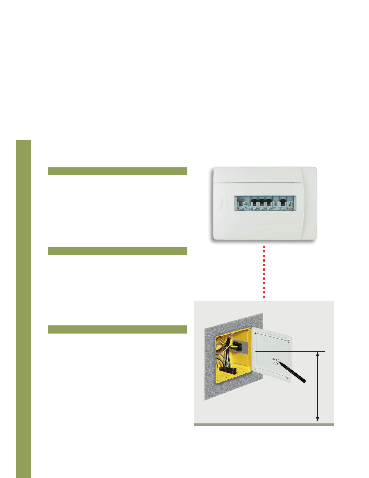
A minimum height of 17.5 cm from the floor is recommended. If possible, 30cm approximately.
Normally, the main junction box should be installed under the electric distribution board.
Switchboard
30 cm
Main junction box
Positioning
of junction boxes
Page 45

CÉLIANE TECHNICAL GUIDE
SCS BUS SYSTEM
III-87
OK
Junction boxes should be installed, based on the floor plan, including the possible distribution of the furniture:
• Nearby the hydraulic manifold of the temperature control
system
It is also recommended that the boxes are NOT installed:
• Behind large pieces of furniture or wardrobes
• Behind flush mounting appliances
• In particularly visible positions
• In easily accessible locations, for maintenance purposes
• In passage areas (eg. landings), or areas not used regularly
1234
C1C2
1234
C1C2
1234
C1C2
1234
C1C2
Electrovalve
actuators
Junction
box
Hydraulic
manifold
Box
Electrovalves
Page 46

SCS BUS SYSTEM
GENERAL RULES FOR INSTALLATION
III-88
The components must be installed at the following heights from the ground.
MINIMUM HEIGHTS RECOMMENDED HEIGHTS
90 cm
Height of handles
Fixed burglary alarm IR sensors and controls
70÷80 cm
Headboard sockets and controls
30 cm
Wall mounting sockets
(electricity, telephone, TV, data transmission)
17,5 cm
Wall mounting and wall sockets
7 cm
Sockets on conduit supports or skirting boards
4 cm
Sockets on towers, or protection shields protruding from floor
The positioning of wall boxes varies depends on the type of devices they will house (controls, IR sensors, temperature sensors,
video cameras etc.).
Positioning
of wall boxes
Page 47

CÉLIANE TECHNICAL GUIDE
SCS BUS SYSTEM
III-89
RECOMMENDED HEIGHTS
265 cm
Sockets for the powering of the kitchen hood and fan
230 - 250 cm
Natural gas detectors (20-40 cm from ceiling)
burglar-alarm siren and loudspeakers
up to 225 cm
Video cameras, adjustable IR sensors, pushbuttons
and cord pull switches for showers and baths,
sockets for suction fans, for bathrooms without window
160 cm
Audio and video door entry systems,
Touch Screen, Video Display, Multimedia Touch Screen, Local Display
150 cm
Temperature control sensor - sockets and light controls
inside boxes and cellars
110 cm
Controls and sockets in bathrooms and on the kitchen
worktop
100 cm
Loud speakers for sitting down listening positions
Inside a box, devices belonging to any house automation system may be installed together with power devices, with the exclusion of:
• General control, and illumination control devices (actuators, dimmers, heating devices), together with temperature control devices
(sensors).
• Any type of actuator or power device, together with data transmission, telephone or TV signal devices.
+
3
+
2
+
1
-
1
-
2
-
3
OFF
A
Page 48

SCS BUS SYSTEM
GENERAL RULES FOR INSTALLATION
III-90
Systems may be installed using two different types of structures or modes of distribution:
• FREE SYSTEM;
• STAR SYSTEM.
The choice is based on installation needs, functions, and wall limitations.
The free wiring system is normally used for the traditional
distribution of power sockets. It is also suitable for My Home
Legrand systems, light and shutter automation, temperature
control and burglar alarm systems.
Star wiring is used for video intercom, sound, data
transmission, telephone, TV and SAT signal systems.
Example of free wiring systems
Example of star wiring systems
Example of star wiring systems
device
junction
box
power supply
Example of free wiring systems
device
junction
box
power supply
siren
Type of wiring
Page 49

CÉLIANE TECHNICAL GUIDE
SCS BUS SYSTEM
III-91
The distribution between the electric distribution board and the
junction boxes must be of the star type. Use a number of ducts
suitable for the systems / services being served.
Install additional conduits, even if empty, for future system
expansions.
It is recommended that 32 mm ducts are used.
DISTRIBUTION BETWEEN THE DISTRIBUTION BOARD AND JUNCTION BOXES
The distribution between junction boxes and wall mounting
boxes must be of the free system type. Use a number of ducts
suitable for the systems / services being served.
It is recommended that ducts with a diameter of at least 20 mm
are used.
DISTRIBUTION BETWEEN JUNCTION BOXES AND WALL MOUNTING BOXES
Page 50

SCS BUS SYSTEM
GENERAL RULES FOR INSTALLATION
III-92
The cables for some applications may be installed inside the same conduits or pipes of the standard electric power supply
system. This enables important savings, both in terms of installation works and costs.
My Home Legrand applications Grouping with power cables
Temperature control
YES
Automation
YES
Sound system
NO
Burglar alarm
YES
Video door entry and home video surveillance
(Note 1)
Control
(Note 2)
Although for some applications it will be possible to have
the power system cables in the same ducts used for the My
Home Legrand
system, it is recommended that this solution is
only implemented for refurbishments. For new buildings it is
recommended that such systems have their own dedicated ducts,
separate from the electric power supply.
(Note 1) If the recommended cables are used for these systems, safety is guaranteed in terms of electrical insulation. However no guarantee is given for correct operation due to possible disturbance that may
occur due to the My Home Legrand system cables being grouped with the electric power cables.
(Note 2) For the following systems, only My Home Legrand system cables can be installed in the same ducts as electric power supply cables: Automation and Temperature Control.
The following table shows the My Home Legrand applications / systems, which cables may be installed in the same duct as the
power supply wiring (however, under no circumstances these should be installed in the same conduits as 380 Vac power supply
cables).
Grouping cables
in the same duct
Page 51

CÉLIANE TECHNICAL GUIDE
SCS BUS SYSTEM
III-93
The separation of electric power supply cables from signal
cables MUST also be ensured inside junction boxes and the
electric distribution board. Attention must therefore be paid
when positioning the entrance of the ducts to the junction boxes
and the electric distribution board.
The light automation, shutters automation, burglar alarm, and
temperature control GREY SCS BUS MAY be installed in the same
ducts and boxes as the electric power cables.
The video handset, HOME VIDEO SURVEILLANCE, and sound
system WHITE SCS BUS, MAY run in the same ducts as the data
transmission, telephone, and TV-SAT signal cables, but IT MUST BE
separated from the electric power supply cables.
5739 99
UTP 5 multi-couples
(white)
0492 31/32
(grey)
Page 52

SCS BUS SYSTEM
GENERAL RULES FOR INSTALLATION
III-94
The following table indicates the cable to be selected based on the application. It must be considered that two or more systems
with different cables may be integrated with each other using the 035 62 interface.
■
●
Recommended cables (in accordance with installation regulations). Cables that may be used (for each system current installation regulations must be
checked).
NOTE (1): Compulsory for the underground sections of the individual systems
NOTE (2): Cable recommended for connection of the contact interface with the corresponding
magnetic contacts.
Automation
Temperature control
Sound system
Burglar alarm
Video door entry and
home video surveillance
Control
0492 31/32
(grey)
■
■ ■
■
■
●
●
■
(white)
UTP 5
UTP 5E
●
● ●
●
●
●
●
(1)
●
(1)
●
●
●
(1)
(2)
(2)
5739 99
●
● ●
●
Selection table
for the cable
APPLICATIONS
Page 53

CÉLIANE TECHNICAL GUIDE
SCS BUS SYSTEM
III-95
CABLE 5739 99
For video system, Legrand produces a dedicated cable, made
of two twisted conductors with a section of 0.50 mm
2
each. This
cable ensures the best performance of the video system (greater
distance between Entrance Panel and Handset, when compared
to other cables).
In addition, differently to standard cables, which are not suitable
for underground installation even when inside ducts, this cable
may be installed underground provided that it is protected by
suitable ducts.
WARNINGS:
although the construction of the white cable, 5739 99 guarantees 300/500V electric insulation, it does
not however guarantee immunity from disturbances that may occur if this cable is installed inside the
same ducts as 230V power supply cables.
These types of installations are not recommended.
WHITE CABLE for Video Handset, HOME VIDEO SURVEILLANCE and Sound System
CABLE 492 31 AND 492 32
This cable has been designed for the installation of BUS systems
for the following applications: Automation, Temperature Control
and Burglar alarm. This cable can be used for the distribution
of the power supply and operating signals. With the 300/500V
insulated BUS cable, and the terminal protection cover, with
which all devices are fitted, the systems may also be installed in
the same boxes and ducts as the electric power supply lines (230
Vac).
GREY CABLE for Automation, Temperature control and Burglar alarm
TECHNICAL FEATURES
• SCS sheathed pair made up of 2 flexible wires, sheated,
unshielded;
• Insulation voltage: 300 – 500 V.
Coil length
White 5739 99 200 m
Grey
0492 31 100 m
0492 32 500 m
PLUG-IN TERMINAL
The devices connected to the SCS BUS using a screw plug-in
terminal. With the plug-in terminal, it is possible to wire the
system in advance and connect the devices just before the
running test.
screw plug-in terminal
Page 54

SCS BUS SYSTEM
GENERAL RULES FOR INSTALLATION
III-96
This operation for the arrangement of the electric system
consists in marking the paths of the connection ducts on the
walls. These paths may be vertical or horizontal.
Diagonal paths must be avoided unless, they must follow an
inclination of the wall or ceiling. Inside the ceiling and under the
floor, ducts may be installed as desired.
The distribution of wall boxes and loads/users, depends on the
type of room and the type of load to be connected.
Layout
of the ducts
NO
NO
OK
OK
OK
OK
Page 55

CÉLIANE TECHNICAL GUIDE
SCS BUS SYSTEM
III-97
When designing a light automation system, comply with the following installation requirements:
• If various loads are to be installed in the room, controlled from
several points (DIN actuator inside a junction box), the duct
must go from the wall box to the box, and from the load to the
box itself.
• If a load with light adjustment must be installed (DIMMER), the
actuator shall be installed inside the distribution board, and the
ducts will be installed in line with the above prescriptions.
•
The bending radiuses of the “main” paths must be such that all
risk of damage to cables is avoided,
• Wall ducts must be horizontal, vertical or parallel to the wall
edges. Diagonal path are only allowed for VERY short sections,
•
Any exposed wires may follow the shortest path,
•
Any wires installed inside ceilings or underfloor may follow the
shortest path.
• If shutter control is to be installed, the duct must run directly
from the wall box to the load.
When designing a shutters automation system, comply with the following installation requirements:
For all My Home Legrand application, when marking out the paths of the ducts, the following recommendations should be followed:
Power cable
M
Dimmer actuator
in the distribution board
Automation BUS
Power cable and
Automation BUS
Power cable and
Automation BUS
Power cable
and Automation BUS
M
Power cable and
Automation BUS
Power cable and
Automation BUS
Page 56

SCS BUS SYSTEM
GENERAL RULES FOR INSTALLATION
III-98
• When connecting a DIN amplifier in flush mounting box, two
separate dedicated ducts must be installed.
Power cable
Sound
system Bus
When installing a Sound system, comply with the following
installation requirements:
Cavo energia
BUS
diffusione
sonora
Inside the home, cables must be installed inside protective ducts
made of insulating material, embedded in floor, walls or ceilings.
For boxes and cellars, due to the difficulty in embedding the
components inside the walls (concrete in boxes and often less than
10 cm wall thickness in cellars), it is preferable to leave ducts and
enclosures exposed. The path of the ducts must take into account
the possibility of containing cables connecting different systems.
For the installation of flush mounting components, corrugated
tubes of different colours should be used. This will make
installation and individuation of the system easier. It is
recommended that only ducts with a minimum diameter of 25 mm
are used.
Automation
Power supply
Temperature control
Power management
Burglar alarm
Telephone system
Data network
TV/SAT
Video handset system
Sound system
Data network
TV/SAT
Layout
of the ducts
Page 57

CÉLIANE TECHNICAL GUIDE
SCS BUS SYSTEM
III-99
When installing a burglar-alarm system, comply with the following installation requirements:
• A dedicated duct must be installed for connection between
the distribution board (burglar-alarm power supply) and the
external siren.
• When connecting the burglar-alarm control unit to a telephone
dialling device, install two separate ducts, one for the burglaralarm BUS, and one for the telephone cable.
M
Electric
distribution
board
Burglar-alarm
BUS
Outdoor
siren
• When connecting magnetic contacts (windows), separate direct
ducts must be installed, with separate boxes for the housing of
the contact interface (DIN or BASIC).
Basic control
Burglar-alarm
BUS
2 pair cable
for magnetic contacts
Power cable
and Automation BUS
Power cable
DIN contacts
interface
BASIC contact
interface
Telephone
cable
Burglar-alarm
BUS
C1 C2
035 73
C1TTC2
N2
Z2
MOD1
Z1
N1
MOD2
67513
SCS
T_C1 C2
_ _
Page 58

SCS BUS SYSTEM
GENERAL RULES FOR INSTALLATION
III-100
When creating a My Home Legrand system, it is recommended that the controls are installed following some rules that will
both facilitate and enhance the use of the system.
GENERAL CONTROLS
It is preferable to install general controls for SHUTTERS and LIGHTS
nearby the main entry of the house, so that lights may be switched
on and off, and shutters may be opened or closed, from a single
point, before going out, or when coming back in the house.
bedroom
bathroom
kitchen
main
bedroom
living room
General lights
controls
General shutters
controls
GENERAL ROOM CONTROLS
bedroom
bathroom
kitchen
main
bedroom
living room
General room controls may be used to control a range of
actuators. They should be installed by the entrance of the room to
be controlled.
LIVING AREA control
(switches on or off all living room
and kitchen lights)
NIGHT AREA control
(switches on or off all the
bedroom lights)
Positioning of controls:
practical installation examples
Page 59

CÉLIANE TECHNICAL GUIDE
SCS BUS SYSTEM
III-101
4 SCENARIOS CONTROL
TOUCH SCREEN
It is recommended that 4 scenario control are installed nearby the
main house entrance and at the points from where the whole house
must be controlled. For example, installation in the bedroom makes
it easy to lower all shutters and switch all lights off before going
to bed.
4 Scenarios control
bedroom
bathroom
kitchen
main
bedroom
living room
main house
entrance
Touch Screen must be installed in a central position, so that it is
visible and easily accessible from any room in the house.
Touch Screen enables control and management of all home
applications.
bedroom
bathroom
kitchen
main
bedroom
living room
Touch Screen
Page 60

SCS BUS SYSTEM
GENERAL RULES FOR INSTALLATION
III-102
It is recommended that in private homes the Multimedia Touch Screen and the PC with VISUAL software are installed in a central
location. For industrial and service sector environments, they should be installed in the reception area.
The VISUAL software enables customisation of the pages and the functions that may be controlled.
MULTIMEDIA TOUCH SCREEN AND PC WITH SOFTWARE VISUAL
It is recommended that video handsets and handsets are installed in areas of the home that can be easily reached, both at daytime and
night time. They have a double function, as they enable receiving calls from the entrance panels and control of the My Home Legrand
applications installed inside the home.
VIDEO HANDSETS AND HANDSETS
bedroom
bathroom
kitchen
main
bedroom
main house
entrance
living room
bedroom
bathroom
kitchen
main
bedroom
living room
Multimedia Touch Screen
Video Display
Positioning of controls:
practical installation examples
Page 61

CÉLIANE TECHNICAL GUIDE
SCS BUS SYSTEM
III-103
Physical configuration is completed by fitting special connection
components called configurators in appropriate housings of each
device, using a special tool. Configurators are distinguished by
numbers, letters, colour, or graphic representations.
This procedure is recommended for low or medium complexity
systems. For systems consisting of several devices, for houses
on several floors, hotels and the service sector, the virtual
configuration described in the following pages is recommended.
PHYSICAL CONFIGURATION
The configuration is a necessary for assigning an address to
the device within the system and set its operating mode.
A preliminary definition of the configuration, will help identify
which functions should be included in the system, how
many devices should be installed, and where they should be
installed within the house. Two types of configuration are
possible: physical configuration and virtual configuration.
Numbered
configurator
Configurator
housings
Description of the
configurator housings
Tool for the fitting
of the configurator
For systems with several devices, the configuration process may
be greatly simplified by using, computer, as an alternative to the
manual configuration procedure.
This type of configuration, called “virtual configuration”, makes it
possible to configure each device without the use of the standard
alphanumeric configurators. The address and the operating
mode of the device is set using a special software installed on the
computer; this solution is particularly suited to large system, as
it allows modification of the configuration at any time, without the
need for manual intervention on each device.
Virtual configuration may be used only in Automation systems:
both in individual systems, and also in case of several systems
integrated with each other in “logic extension” mode.
VIRTUAL CONFIGURATION
T5H 250V
06W48
036 52
IP30
230 ±10% V 50-60Hz
I =300 mA
sortie 27V 1,2A
T=5÷40°C
035 60
N646
MAX
SCS BUS
NOTE: PC not supplied
USB USB
SCS
AV IN
SCS
AV OUT
SCS
AI
DC
SCS
AV
ETH
Speed
Full
Link
Aux
System
5739 92
LAN (crossed)
Rolling shutter
control
Dimmer
control
Rolling shutter
control
Flush-mounting
actuator
DIN dimmer
NC21 3 4
036 56
C1
DIN actuator
Power supply
Web server
Only automation system
~ Vac
Basic configuration
concepts
Page 62

Page 63

Automation system
General features ......................... 000
General rules for installation .... 000
Wiring diagrams ......................... 000
Configuration .............................. 000
Automation system
>
Page 64

SCS BUS AUTOMATION SYSTEM
GENERAL FEATURES
III-106
The My Home Legrand Automation system, allows you to
manage functions in a simultaneous and integrated way.
To date, these functions have been performed with special
and complex electrical devices such as:
• Lighting control
• Control for shutters and/or electric curtains, fans,
exhausters, etc.
Compared to the devices of a conventional electrical
system, Automation devices have an electronic circuit with
a programmable logic and are connected in parallel with a
2-conductor SCS BUS cable for sending information and with
low voltage (27 Vdc) electric power.
There are two types of devices in the system:
• Controls, connected only to the SCS BUS cable;
• Actuators, connected both to the SCS BUS cable and to the
power line for managing the connected load.
Introduction
to the Automation system
Pushbutton/switch
CONTROL
SCS BUS
ACTUATORS
LOAD
ON/OFF
general control
Scenary
touch
Touch Control
multifunction
Basic contact
interface
DIN
Dimmer
Lighting
Rolling
shutter
27 Vdc
DIN
actuator
Power supply
L
N
230
Vac
230
Vac
Page 65

CÉLIANE TECHNICAL GUIDE
sCs Bus automation system
III-107
When the Automation system devices are configured properly,
it is possible to manage the load as follows:
• Control for a single load (lamp, rolling shutter, etc.);
• Control for one or more load groups (for example, only the
shutters on the first floor, north side, etc.);
• Simultaneous management of all loads (for example,
general deactivation of all lamps in the house and/or
closing of all rolling shutters).
It is also possible to carry out special functions - which can
hardly be achieved with conventional electrical systems.
These functions are called scenarios, which consist of a set of
simultaneous controls used for arranging the room according
to the user’s lifestyle.
An example of a scenario can be represented by the
simultaneous activation of lights, shutters, etc., which can be
set by the user after getting home by using one single control
device or by using the Touch Screen menu. If the Automation
system is integrated with Sound system and Temperature
control system, the scenario can also set up a room with
background music and with the required temperature.
DIN
Dimmer
Rolling shutter
control
Touch Screen
Local
Control
Rolling
shutter
Lighting
Gateway
SCS/ZigBee
®
Radio
control
Radio remote
control
RADIO SYSTEM
DIN
actuator
Page 66

SCS BUS AUTOMATION SYSTEM
GENERAL FEATURES
III-108
Most devices of the Automation system are installed with the
same procedures used for conventional electrical system
devices, namely:
• Flush-mounted in device-holder boxes;
• In switchboards on DIN rail.
Some devices are installed with different procedures; for
example actuators can be directly installed inside the load to
be controlled.
The advantages given by the installation flexibility of the
radio devices can be used for expanding a wire system in
rooms that are not set up for SCS BUS cabling.
This can be achieved by connecting Gateway SCS/ZigBee
®
:
• Receiving to control any actuator of the wire system by a
radio control (remote control or flat control);
• Transmitting for controlling any radio actuator by a wire
system control.
Wire-system devices communicate with each other
through a two-conductor SCS BUS cable.
(Sheathed no-polarised connectors)
The range includes devices for Basic functions such as
controls and actuators as well as devices for advanced
functions such as the scenario control, the IR remote
control receiver and the Touch Screen.
TYPE OF SYSTEMS AND DEVICES
COMBINED RADIO/WIRE
WIRE SYSTEM
Introduction
to the Automation system
Actuator
Touch radio control
for rolling shutter
Radio receiving
interface
Rolling shutter
control
SCS BUS
Rolling
shutter
Control
DIN actuator
SCS BUS
Lighting
Rolling
shutter
DIN actuator
Page 67

CÉLIANE TECHNICAL GUIDE
sCs Bus automation system
III-109
THE DEVICES CAN BE INSTALLED:
In flush-mounting boxes On Din Rail
Next to the load
DIN actuator
Actuator
Basic devices in flush-mounting boxes so that the existing
controls can be used
SCS BUS
Contact
interface
SCS BUS
Traditional
pushbutton
Rolling shutter
Page 68

SCS BUS AUTOMATION SYSTEM
GENERAL FEATURES
III-110
be distinguished by their number, letter or graphic label or
by virtual configuration. The destination address or source
address of the control as well as the operating mode of the
device (activation/deactivation or adjustment of a load) shall
be assigned with the configuration inside the system.
In order for each SCS BUS system device to perform its
functions properly, it must be appropriately configured, thus
assigning its functioning mode and address.
This procedure, called configuration, is carried out by
inserting push-in devices, called configurators, which can
DEVICE CONFIGURATION
Introduction
to the Automation system
PHYSICAL CONFIGURATION
Numbered
configurator
Configurator
housing
Description of the
configurator housing
Tool for insertion
of configurator
The devices communicate
with each other because
they have the same
configuration
➔
Power supply
DIN actuator
INFORMATION
SCS BUS
230 Vac
➔
Page 69

CÉLIANE TECHNICAL GUIDE
sCs Bus automation system
III-111
VirtualConfigurator, in a personal computer.
The configuration is then transferred to the device involved by
LAN connection.
To simplify the configuration of systems with many devices,
“virtual configuration” is available. The configuration
parameters are no longer established manually with the
configurators, but through the use of a special software called
VIRTUAL CONFIGURATION
SCS BUS
Computer with
VirtualConfigurator software
LAN (crossed)
Web server
Automation system
Lighting
Rolling
shutters
Page 70

SCS BUS AUTOMATION SYSTEM
GENERAL FEATURES
III-112
BASIC CONTROL DEVICES
From a functional point of view, the control with the single
key cover can become integrated with a traditional closing
contact (pushbutton or switch); conversely, the double key
cover (tilting) can become integrated with a traditional
exchanging contact.
Control devices allow you to control the state of the actuators,
thus executing different functions: ON, OFF, timing, etc.,
which depend on the functioning mode that has been
assigned to them through an appropriate configuration.
The electronic part of these devices is separated from the
mechanical operating part so that one can choose the type,
number and size of the control pushbuttons.
The device can be modular, thus meeting the different
installation requirements and different functions required by
the user.
Control devices
Controls Push button mode Switch mode Key cover
Pay attention to the left and right silk-screen printed single key covers
Single right
key cover 1 module
Single left
key cover 1 module
Control key
Upper
pushbutton
Lower
pushbutton
LED
LED
LED brightness
regulation pushbutton
Cover for control
Page 71

CÉLIANE TECHNICAL GUIDE
sCs Bus automation system
III-113
The following devices belong to this category:
• Basic and special control
• Touch controls
• Passive IR detector
• IR receiver
These components are able to send controls for single loads
(lamps, exhausters, air-conditioners, etc.) and to double loads
(motor for rolling shutters, curtains, etc.).
Infrared devices have the advantage of sending their control
to the SCS BUS when they are activated by a remote control
or by the presence of a person; conversely, the controls must
be operated locally from the user.
LED
All controls are provided with an indicator which indicates the state of the control (activated or deactivated), thus enabling
its identification in the dark.
Touch
control multifunction
2 modules
control device
Passive
IR detector
Upper
pushbutton
Lower
pushbutton
Page 72

SCS BUS AUTOMATION SYSTEM
GENERAL FEATURES
III-114
It is possible to create scenarios, in other words particular
environmental comfort situations represented, for example,
by the activation of a few lights at a given brightness level
and by the position of some shutters in order to watch TV or
read a book, according the user’s lifestyle. Another example
of advanced scenario that can be carried out with different
integrated My Home Legrand systems is represented
by the activation of particular background music, by the
temperature setting and by the brightness level of the house
when receiving friends. The above-mentioned scenarios
are managed by particular devices able to memorize all the
controls determining the scenario and that the user can set
simultaneously by pressing just one pushbutton.
CONTROL DEVICES FOR ENHANCED FUNCTIONS – SCENARIOS
This cathegory includes devices that provide special and advanced automation functions.
Control devices
Scenario programmer 035 65
for advanced scenarios
TOUCH SCREEN
MULTIMEDIA
TOUCH SCREEN
LOCAL DISPLAY
SYSTEM MANAGEMENT SCENARIOS
Page 73

CÉLIANE TECHNICAL GUIDE
sCs Bus automation system
III-115
Scenario module 035 51
to save max 16 scenarios
The following functions can be executed by the control
devices:
• Scenario module 035 51 with two DIN modules to store 16
scenarios for the automation, sound system, temperature
control and Video door entry applications.
• Scenario programmer 035 65 for the creation and
management of enhanced scenarios, also depending on
events in time, state of the systems and other.
The scenarios stored by the above devices can be selected
by using the basic and special control, the IR receiver for
remote control, the Scenary Touch, the Touch Screen and the
Multimedia Touch Screen.
IR RECEIVER +
REMOTE CONTROL
SCENARIO CONTROL
BASIC AND SPECIAL CONTROL
SYSTEM MANAGEMENT SCENARIOS
Page 74
SCS BUS AUTOMATION SYSTEM
GENERAL FEATURES
III-116
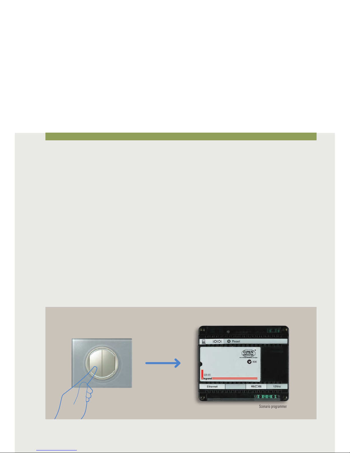
CONTROL DEVICES FOR ENHANCED FUNCTIONS FOR SCENARIO PROGRAMMER 035 65
The device, installed in a My Home Legrand system, performs
the scenarios programmed with the 035 65 software (supplied
with the CD which comes with the device) after the following
activation, deactivation, block or unblock events:
• Pressing a control pushbutton (configured in CEN mode);
• Switching a light ON or OFF (apart from the dimmer light
points);
• Operation of automatic devices (movement of rolling
shutters);
• An event managed by one of the nine auxiliary channels;
• A time or a date;
• A burglar-alarm system event;
• A condition which occurs on the temperature control
system
• A call from the entrance panel or the state of a video door
entry system camera.
• A sound system event
After these events the scenario programmer 035 65 can then
control the My Home Legrand system applications.
The performance of a conditioned scenario matched to a
particular time or date allows for example simulating being at
home through the automatic activation of the rolling shutters
or the lighting while away from home and at prefixed times.
An automation system control pushbutton can be
programmed so that, if pressed, it blocks all the scenarios
being run (Panic Key).
Control devices
Scenario programmer
Control with CEN
configurator
Page 75

CÉLIANE TECHNICAL GUIDE
sCs Bus automation system
III-117
Example of scenarios
Two examples of scenarios which are possible with the
scenario programmer 035 65 device are given below.
The control device keys are associated with the scenarios to
activate with the program supplied with the programmer.
Light sensor
Scenario 2 - Garden lights:
Following activation of the control device, every night at 8.00
pm, when the light detector detects that outside is dark, the
garden lights will automatically switch-on.
038 42
038 41
A =
PL =
1
1
M =
CEN
038 41
A =
PL =
1
1
M =
CEN
Scenario 2 - Returning home:
If the light detector detects that it is still daytime, when the
key of the control device is pressed, the shutters open, but
the lights stay off. If on the other hand it is already dark
outside, the lights come on, but the shutters stay closed.
Light sensor
Page 76

SCS BUS AUTOMATION SYSTEM
GENERAL FEATURES
III-118
CONTROL DEVICES FOR ENHANCED FUNCTIONS
LOCAL DISPLAY
The Local Display is a room control to manage the scenarios,
sound system and temperature control. With just one touch
the 4 icons can call 4 scenarios.
MULTIMEDIA TOUCH SCREEN
The Multimedia Touch Screen is a control device, like the
Touch Screen, manages all the system functions.
In systems combined with Sound System and Video door entry
it can manage multimedia functions and answer calls from
the entrance panel.
Touch Screen
TOUCH SCREEN
The colour Touch Screen is a room control for all My Home
Legrand functions. It is possible to switch the lights on
and off, lower or lift the shutters, control the watering
system in the garden, adjust the temperature in all rooms,
automatically activate scenarios according to logical or time
conditions, etc. The display starts with a “home page”.
The applications that can be managed are shown graphically
inside the home page. When you touch the icon of the
application you want to manage (e.g. lighting), a page will be
displayed. This page will contain the customised icons of the
light points. Again, with a simple touch on the chosen icon,
the lamp or lamps associated to it will turn on or turn off.
The Touch Screen can be easily installed in a flush-mounting
box.
Control devices
Local Display
Multimedia Touch Screen
Page 77

CÉLIANE TECHNICAL GUIDE
sCs Bus automation system
III-119
Actuators
DIN MODULE ACTUATORS
These devices are suitable for centralised installation in
electrical panels and switchboards. Available in the 1, 2 and
4-relay versions for control of individual or double loads
(motors for electrical blinds), they are fitted with a load
control pushbutton to perform load operation tests.
With these actuators, the rear DIN adaptor and the front
cover can be removed to reduce the size and therefore allow
for installation in cable trays, junction boxes, false ceilings,
shutter boxes, etc.
Load connection clamps
Load control pushbutton
Configurator housing
DIN actuator for installation in switchboards
Example of switchboard installation
Removable
front cover
Removable adaptor for
installation on IN guide
in central units
Example of junction box installation
20 mm only
Page 78

SCS BUS AUTOMATION SYSTEM
GENERAL FEATURES
III-120
Actuators
These devices perform the controls received, and monitor the connected load in a similar way to an electro-mechanical relay.
For this reason, they must be connected to the SCS BUS cable using the removable terminals as well as to the 230 Vac supply
line of the load.
OVERVIEW OF THE ACTUATORS
This table lists the actuators divided by type of use.
Actuators BUS
absorption
Driven loads Dissipated
power
Incandescent
/halogen
lamps
Resistive
loads
Fluorescent
lamps
Electronic
transformers
Ferromagnetic
transformers
M
Rolling
shutter
motors
038 41
22 mA 10 A
2300 W
16 A
3500 W
4 A
1000 W
4 A
1000 W
4 A cos ϕ 0.5
1000 VA
- 1.5 W
038 42
28 mA
(Single loads)
15.5 mA
(Interlock)
6 A
1400 W
10 A
2300 W
1 A
250 W
1 A
250 W
2 A cos ϕ 0.5
500 VA
2 A
500 W
1.7 W
038 44
40 mA
(Single loads)
22 mA
(Interlock)
2 A
500 W
6 A
1400 W
0.3 A
70 W
0.3 A
70 W
2 A cos ϕ 0.5
500 VA
2 A
500 W
3.2 W
036 56
30 mA -
-
-
-
2 A
460 W
MAX 10 ballast
tipo T5, T8,
compatte o
driver per led.
-
-
-
-
-
-
0.5 W
036 52
9 mA 0.25 – 4 A
60 – 1000 W
0.25 – 4 A
60 – 1000 W--
-
-
0.25 – 4 A
60 – 1000 VA
-
11 W
(Max. Load 1000 W)
5 W
(Max. Load 500 W)
036 53
9 mA -
-
-
-
-
-
0.25 – 1.7 A
60 – 400 VA--
-
-
11 W
2 43 5
1
1 3
2 4
3
2
1
Page 79

CÉLIANE TECHNICAL GUIDE
sCs Bus automation system
III-121
Actuators BUS
absorption
Driven loads Dissipated
power
Incandescent
/halogen
lamps
Resistive
loads
Fluorescent
lamps
Electronic
transformers
Ferromagnetic
transformers
M
Rolling
shutter
motors
026 02
-
-
16 A
3680 W
-
-
4.3 A
10 (2 x 36 W)
16 A
3680 VA
16 A
3680 VA
-
-
-
-
026 11
165 mA -
-
-
-
50 W
1000 VA
-
-
-
-
-
-
-
-
026 21
-
-
4.3 A
1000 W
-
-
-
-
4.3 A
1000 VA
4.3 A
1000 VA
-
-
-
-
026 22
-
-
1.7 A
2 x 400 W
-
-
-
-
1.7 A
2 x 400 VA
1.7 A
2 x 400 VA
-
-
-
-
Page 80

SCS BUS AUTOMATION SYSTEM
GENERAL FEATURES
III-122
Interfaces
The automation also allows you to use traditional devices or
a personal computer, thus allowing high flexibility of use for
external systems. The connection between modern digital
SCS BUS technology and a traditional cabling component or
PC is represented by special devices called interfaces.
As a result, these devices interpret information of the
traditional world, thus translating it into signals compatible
with SCS BUS logical devices.
These interfaces are:
• DIN module contact interface 035 53
• Basic module contact interface 5739 96
• SCS/SCS gateway 035 62
• SCS/OPEN KONNEX interface 5739 93
(see CONTROL AND INTEGRATION section).
• WEB SERVER 5739 92
This device can be used to connect traditional devices - like
switches and pushbuttons - to the BUS, thus extending the
use of BUS to pre-existing traditional systems.
Thermostats, control systems, humidity sensors, wind
sensors, etc. can also be connected.
CONTACT INTERFACE IN DIN MODULE
Thanks to its limited size, this device can be installed behind
other devices; indeed, in a 503E box, the interface can be
installed just behind traditional devices (e.g.: switches,
pushbuttons) or reduced-thickness electronic devices
(e.g. controls, sensors). Thermostats, humidity sensors,
wind sensors, etc. can also be connected. Such a simple
installation solution makes it easier to convert traditional
electrical systems into home automation systems, since
existing flush-mounted boxes can be left in place, with no
need for any masonry.
CONTACT INTERFACE IN BASIC MODULE
SCS BUS
DIN contact interface
035 53
External
devices
Prestige switch
(reuse of historical
devices)
SCS BUS
Basic contact interface
5739 96
External
devices
Prestige switch
(reuse of historical
devices)
Page 81

CÉLIANE TECHNICAL GUIDE
sCs Bus automation system
III-123
035 62
This device, coming inside a DIN container, allows for
communication between SCS-technology BUSes, even when
these have different functions. This interface allows to extend
existing Automation systems.
SCS/SCS GATEWAY
These gateways connect systems based on the SCS
technology with standard KNX systems.
SCS/OPEN KNX GATEWAYS
SAVING
Thermoregulation
Energy Management
SAFETY
Burglar alarm system
Teleassistance
Technical alarms
Home video control
COMMUNICATION
Video door entry
systems
2-wire digital
system
COMFORT
Lighting
Shutter automation
Scenarios
Sound diffusion
Web server
5739 92
SCS/OPEN Konnex
5739 93
BUS MY HOME
LAN
Page 82

SCS BUS AUTOMATION SYSTEM
GENERAL RULES FOR INSTALLATION
III-124
A maximum of 9 room addresses can be
managed in a single system. For every
room it will be possible to manage up
to a maximum of 9 addresses, hence 9
actuators (a total of 81 addresses).
Other associations to one or more groups
are added to these addresses.
EXTENDED SYSTEMS (LOGICAL EXPANSION)
Within big houses or in service/industrial sectors, there may be the need to carry out Automation systems characterised by a number
of devices that may exceed the above-mentioned address limit. In this case it is possible to carry out a complex Automation system by
connecting several Automation systems (maximum 9) to a common bus (main riser), using SCS/SCS gateway - 035 62 - configured in
“logical expansion” mode.
Maximum number of devices
which can be configured
Max 81 addresses
Max 10 x 81 addresses
OUT
IN
SCS/SCS
gateway
035 62
Automation
system No. 2
Basic contact
interface
Basic contact
interface
Rolling shutter
control
Rolling shutter
control
Dimmer
control
Dimmer
control
Power supply
Power supply
Fan
control
Fan
control
Rolling shutter
control
Rolling shutter
control
Automation
system No. 1
Basic contact
interface
230
Vac
230
Vac
4321
C1 C2
T5H 250V
036 52
4321
C1 C2
4321
C1 C2
4321
C1 C2
IP30
5739 96
Rolling shutter
control
Dimmer
control
Fan
control
Rolling
shutter control
DIN
Actuator
DIN
Actuator
DIN
Dimmer
DIN
Actuator
DIN
Actuator
4321
C1 C2
4321
C1 C2
T5H 250V
036 52
T5H 250V
036 52
4321
C1 C2
4321
C1 C2
4321
C1 C2
4321
C1 C2
4321
C1 C2
4321
C1 C2
IP30
IP30
5739 96
5739 96
DIN
Actuator
DIN
Actuator
DIN
Actuator
DIN
Actuator
DIN
Dimmer
DIN
Dimmer
DIN
Actuator
DIN
Actuator
DIN
Actuator
DIN
Actuator
OUT
IN
C
Power supply
230 Vac
Page 83

CÉLIANE TECHNICAL GUIDE
III-125
sCs Bus automation system
The diagram previously described suggests the representation “at
levels” of the complete system, in which the riser bus connected
to the IN terminal of SCS/SCS gateway
035 62
assumes the
identification of main Riser while each individual system connected
to the OUT terminal is identified with Local BUS.
The integrated system previously described can thus be represented
with the following simplified diagram:
OUT
IN
SCS/SCS
gateway
035 62
Local BUS
Main riser
WARNING: configure SCS/SCS gateway
035 62
for operation in “logical extension” mode,
inserting configurator 2 in position M and configuring the addresses of positions I3 and I4 with values
between 01 and 09, as in the following diagram.
It is important to remember that for the correct operation of an integrated system and thus to use the
device virtual configuration mode as well, the Automation system must be made in agreement with
the type of diagram described.
There are 81 configuration addresses for each system (9 light
points for each of the 9 rooms). In the main riser it is possible to
install control devices configured to send GROUP or GENERAL
controls to some or all of the actuators situated in the single
systems and in the same main riser. POINT-POINT controls
generated inside each single system and on the main riser can
reach the actuators situated in the whole system only if they
are sent from the appropriately configured cross control device
situated on the main riser or on one of the single systems
(max 9) connected. In this case it is possible to address up to a
maximum of 810 devices (81 devices per system x 9 systems +
81 devices on the main riser). If you need to control and execute
the centralised management of the system with Web Server,
Touch Screen and Control Unit, these devices will have to be
installed in the main riser.
FEATURES AND RULES FOR INSTALLATION
Using the control of the system No. 3 it is possible to control the actuator in the system No. 1.
If three or more systems (up to a maximum of 9) must be combined,
these must be connected by means of SCS/SCS gateway
035 62
with a common bus, which from now on we will call “riser”, on
which the control, activation and management (for example Touch
Screen) devices can also be installed because they belong to the My
Home Legrand Automation system. The riser cannot be made, for
example, with a Burglar-alarm or 2 wire Video door entry system.
For the combination of different systems see the indications given in
the
Integration and Control section.
Max 81 addresses
Main riser
Max 81 addresses
Local BUS
Actuator
Max 81 addresses
Control
Max 81 addresses
Local BUS
Local BUS
Local BUS
Automation system No. 2
Automation system No. 1
I1 = –
I2 = –
I3 = –
I4 = 1
M = 2
I1 = –
I2 = –
I3 = –
I4 = 2
M = 2
A = 3
PL = 6
I1 = –
I2 = –
I3 = –
I4 = 3
M = 2
A = 3
PL = 6
I = 1
I1 = –
I2 = –
I3 = –
I4 = 4
M = 2
OUT
IN
C
035 62
4321
C1 C2
OUT
IN
SCS/SCS
gateway
035 62
OUT
IN
C
Automation system No. 4
Automation system No. 3
OUT
IN
SCS/SCS
gateway
035 62
OUT
IN
C
OUT
IN
SCS/SCS
gateway
035 62
OUT
IN
C
Automation system No. 2
OUT
IN
SCS/SCS
gateway
035 62
OUT
IN
C
Automation system No. 1
Page 84

SCS BUS AUTOMATION SYSTEM
GENERAL RULES FOR INSTALLATION
III-126
Special systems for which the availability of more than 810
addresses is required can be made using one or more Web
Servers 5739 92 and a LAN network which forms the connection
infrastructure.
Referring to the picture below, in this case the extended system
is made up of two or more systems for each of which a maximum
of 810 addresses can be configured. The centralised control of
the functions is obtained through Personal Computer, connecting
directly to the Web Server fixed IP address and working on Web
pages with preconfigured icons.
Maximum number of devices
which can be configured
SCS BUS
Web Server
5739 92
LAN
network
N is the number of the WEB
SERVER connected
Max Nx10x81 addresses
Control
Local BUS
Local BUS
Local BUS
Local BUS
Control
System 3 Max 10 x 81 addresses
Local BUS
Local BUS
Control
SCS BUS
SCS BUS
DISTANZE E NUMERO MASSIMO DI DISPOSITIVI
System 1 Max 10 x 81 addresses
System 2 Max 10 x 81 addresses
OUT
IN
OUT
IN
SCS/SCS
gateway
035 62
Automation system No. 1
Automation system No. 2
OUT
IN
OUT
IN
SCS/SCS
gateway
035 62
Web Server
5739 92
Automation system No. 1
Automation system No. 2
OUT
IN
SCS/SCS
gateway
035 62
OUT
IN
OUT
IN
OUT
IN
SCS/SCS
gateway
035 62
OUT
IN
OUT
IN
SCS/SCS
gateway
035 62
Automation system No. 1
Automation system No. 2
OUT
IN
OUT
IN
SCS/SCS
gateway
035 62
Web Server
5739 92
Page 85

CÉLIANE TECHNICAL GUIDE
III-127
sCs Bus automation system
The maximum number of devices that can be connected to
the BUS depends on their total absorption and on the distance
between the connection point and the power supply. The power
supply unit can deliver up to 1,2 A hence, the maximum number
of devices will be determined by the sum of the absorptions of
the single devices you need to install (see absorption table in
the following pages). For the purposes of the above-mentioned
calculations included in the “Technical features”.
When calculating the absorptions, it is also necessary to consider
the availability of current according to the length of the cable.
When setting up, please observe the following rules:
NOTE:
The maximum current available at the end of the 250 m SCS BUS cable 492 31 is 600 mA.
A
B
A = 250 m max
B = 250 m max
A + B = 500 m max
4321
C1 C2 C3 C4
5
038 44
3) For optimum division of the currents on the BUS line power supply should be
positioned in the middle.
1) The connection between the power supply and the furthest away device must not be
longer than 250 m
2) The overall length of connections should not exceed 500 m (extended cable)
Distances and maximum
number of devices
max 1,2 A with 035 60
max 600 mA with 035 67
max 250 mA between the power supply and the furthest away device
max 500 mA total length
~ Vac
power supply
control
actuator
junction boxes
Page 86

SCS BUS AUTOMATION SYSTEM
GENERAL RULES FOR INSTALLATION
III-128
Limit systems shall be applied to each bus in terms of absorption
and maximum wiring distance, as shown in the previous page.
Therefore, it is not possible to supply a system consisting of two
or more buses with only one power supply unit 035 60, connected
to each other by interfaces configured in “physical expansion”
mode even if the number and type of components connected to
the system do not exceed the set maximum absorption. Positions
I3 and I4 shall be configured according to the configuration of the
Automation devices in the two systems connected to each other.
With reference to the picture, let us suppose, for example, that
I3=2, I4=7:
• On the input bus (IN), the addresses of Automation devices No.
1 must be between A=1 / PL=1 and A=2 / PL=6;
• On the output bus (OUT), the addresses of Automation devices
No. 2 must be between A=2 / PL=8 to the address of the next
interface.
With very extended systems or with current absorption exceeding a limit of 1.2 A supplied by the power unit 035 60, it is necessary to
divide the system into several sections supplied with their own power supply unit and connected between each other with a special
interface (SCS/SCS gateway 035 62) configured in “physical expansion” mode.
PHYSICAL EXPANSION
Distances and maximum
number of devices
A/PL = 11 26
A/PL = 55 99
A/PL = 28 53
1
2
3
SCS/SCS
gateway
035 62
SCS/SCS
gateway
035 62
I1 = –
I2 = –
I3 = 2
I4 = 7
M = 1
I1 = –
I2 = –
I3 = 5
I4 = 4
M = 1
OUT
IN
C
035 62
OUT
IN
C
035 62
230 Vac
230 Vac 230 Vac
OUT OUT
IN IN
Page 87

CÉLIANE TECHNICAL GUIDE
III-129
sCs Bus automation system
When setting up the system, consider the following
recommendations:
1. The buses, connected to the interface input and output, must
be supplied with their own power supply unit; additionally, the
system limits apply for each of them, in terms of absorption and
maximum distance specified.
Therefore, it is not possible to supply a system consisting of two or
more buses with only one power supply unit (035 60), connected to
each other by various interfaces configured in physical expansion
mode even if the number and type of components connected to the
system do not exceed the set maximum absorption.
2. Two interfaces in parallel cannot be connected to the same bus.
3. It is possible to, use up to 4 interfaces in series, which divide the
system into 5 separate sections.
4. The scenario module 035 51 and all the devices that can be
configured using self-learning mode are installed on the stretch of
bus corresponding to its local address. For example if the module
scenarios are configured as A=0 (no configurator), PL=1 it will be
placed on the stretch of system 1.
INSTALLATION RULES
Item Description Absorption from Bus
(power supply: 27 Vdc)
Size Dissipation
Dissipated power with maximum load Maximum load
026 02
4 relays DIN actuator 16 A 5 mA 6 DIN modules
026 11
Ballast DIN dimmer 0 – 10 V 165 mA 6 DIN modules
026 21
DIN dimmer 1000 VA 5 mA 6 DIN modules
026 22
Din dimmer 2 x 400 VA 5 mA 6 DIN modules
026 31
SCS/DALI gateway 5 mA 6 DIN modules
035 51
Scenario module 20 mA 2 DIN modules 0,6 W
035 52
Memory module 5 mA 2 DIN modules 0,1 W
035 53
DIN contacts interface 9 mA 2 DIN modules 0,2 W
035 60
Power supply 230 V 8 DIN modules 11 W 1,2 A
035 62
SCS/SCS gateway IN: 25 mA
OUT: 5 mA
2 DIN modules 1 W
035 67
Power supply 230 V 2 DIN modules 5,3 W
036 52
DIN dimmer 1000 W 9 mA 4 DIN modules 11 W 1000 W
036 53
DIN dimmer 400 W 9 mA 4 DIN modules 11 W 400 VA
036 56
1)
Ballast DIN dimmer 1 – 10 V 30 mA 2 DIN modules 0,5 W
038 41
1)
1 relay DIN actuator 16 A 22 mA 2 DIN modules 1,5 W
038 42
1)
2 relays DIN actuator 10 A 28 mA (single loads)
15,5 mA (interlock)
2 DIN modules 1,7 W
038 44
1)
4 relays DIN actuator 6 A 40 mA (single loads)
22 mA (interlock)
2 DIN modules 3,2 W
672 16
IR receiver 8,5 mA 2 flush-mounting modules
672 17
672 18
Scenario control 9 mA 2 flush-mounting modules
672 41
Basic control 9 mA 2 flush-mounting modules
672 42
Special control 7,5 mA 2 flush-mounting lowered modules
672 43
672 44
Touch control multifunction 20 mA with LED=MIN
25 mA with LED=MED
30 mA with LED=MAX
672 46
672 47
Touch control 20 mA
5739 96 Basic contacts interface 3,5 mA basic module
Dissipation, size and absorption table
NOTE: 1) the dissipated power specified is the one recorded when all device relays are at maximum load. In case of lower loads, dissipated power is reduced and can be calculated using the following formula:
P[mW]=140+400*N+10*[I
1
2
+I
2
2
+...I
N
2
]
P: dissipated power in mW; N: number of loaded relays; I
N
: load current corresponding to the “N” relay.
Install the items having the highest dissipated power (particularly power supplies and dimmers) in the lowest positions of the switchboard to enhance heat dissipation. Do not install devices dissipating power above 5 W next to
each other: leave an empty module between them.
Page 88

SCS BUS AUTOMATION SYSTEM
WIRING DIAGRAMS
III-130
Single
functions
SWITCHING A LAMP ON AND OFF
SWITCHING TWO LAMPS ON AND OFF WITH ON/OFF GENERAL CONTROL
N
L
321
C1
038 41
321
C1
038 41
1 relay
DIN actuator
16 A
1 relay
DIN actuator
16 A
BUS/SS
ControlControlON/OFF
general
control
Power supply
N
L
321
C1
038 41
Power supply
1 relay
DIN actuator
16 A
To other
devices
SCS BUS
Control
230 Vac
230 Vac
To other
devices
A = 1
PL = 1
M1 = O/I
A = 1
PL = 1
M = –
G1 = –
G2 = –
G3 = –
A = 1
PL = 1
M1 = O/I
A = 1
PL = 1
M = –
G1 = –
G2 = –
G3 = –
A = 1
PL = 2
M = –
G1 = –
G2 = –
G3 = –
A = 1
PL = 2
M1 = O/I
A = GEN
PL = –
M1 = O/I
230 Vac
230
Vac
Page 89

CÉLIANE TECHNICAL GUIDE
III-131
sCs Bus automation system
SWITCHING-ON CONTROL FOR BATHROOM LIGHT AND FAN WITH DELAYED SWITCHING-OFF
AUTOMATIC LIGHT SWITCHING-ON AND LOCAL CONTROL OF TIMED ON
OFF
N
L
M
321
C1
038 41
321
C1
038 41
Power supply
1 relay
DIN actuator
16 A
(Master)
To other
devices
SCS BUS
1 relay
DIN actuator
16 A
(Slave)
Control
ON
Bathroom
light
Bathroom
fan
• The light turns on when the IR detector detects a person or
when the control, is pressed. It turns off automatically after
15 minutes.
• The configurators in the AUX positions of the detector and of
the control must have the same value.
N
L
321
C1
038 41
Power supply
1 relay
DIN actuator
16 A
To other
devices
SCS BUS
ControlIR detector
• The ON control turns on the light and the fan at the same time
• The OFF control turns off the light whereas the fan turns off
after 2 minutes (configurator in M=2 of the Master actuator)
230
Vac
230 Vac
A = 3
PL = 1
M1 = O/I
A = 3
PL = 1
M = 2
G1 = –
G2 = –
G3 = –
A = 3
PL = 1
M = SLA
G1 = –
G2 = –
G3 = –
A = 3
PL = 1
M = AUX
SPE = –
AUX = 2
A = 1
PL = 1
M = –
G1 = –
G2 = –
G3 = –
A = 1
PL = 1
M = 6
SPE = –
AUX = 2
230 Vac
230
Vac
Page 90

SCS BUS AUTOMATION SYSTEM
WIRING DIAGRAMS
III-132
Single
functions
MOTOR CONTROL IN ALTERNATED CURRENT FOR ROLLING SHUTTERS, CURTAINS OR
MOTORISED
ROLLING SHUTTERS
MOTOR CONTROL IN DIRECT CURRENT FOR MOTORISED CURTAINS (EXAMPLE 24 VDC)
24 Vdc
+
+
M
4321
C1 C2
038 42
4321
C1 C2
038 42
Power
supply B
Power supply A
Control
To other
devices
SCS BUS
NOTE: It is possible to use direct current motors with other features
(12 Vdc; 24 Vdc; 48 Vdc) by replacing the compatible power supply unit
with the features of the motor (voltage and current), thus verifying the
absorptions of the motor with the actuator relay capacity.
2 relays
DIN
actuator
10 A
2 relays
DIN
actuator
10 A
N
L
M
N
L1L
2
4321
C1 C2
038 42
Power supply
2 relays
DIN actuator
10 A
Control
To other
devices
SCS BUS
L1-N = clockwise rotation
L2-N = anticlockwise rotation
M = motor in AC
with 2 windings
230 Vac
230 Vac
A = 2
PL = 1
M =
A = 2
PL1 = 1
PL2 = 1
M = –
G = –
A = 3
PL1 = 1
M1 =
A = 3
PL1 = 1
PL2 = 1
G = –
M = –
A = 3
PL1 = 1
PL2 = 1
G = –
M = SLA
230 Vac
230
Vac
Page 91

CÉLIANE TECHNICAL GUIDE
III-133
sCs Bus automation system
SWITCHING ON AND OFF AND BRIGHTNESS ADJUSTMENT OF FLUORESCENT LAMPS BY MEANS
OF THE “BALLAST”
SWITCHING ON AND OFF AND BRIGHTNESS ADJUSTMENT OF INCANDESCENCE LAMPS, HALOGEN AND
FERROMAGNETIC TRANSFORMERS
L
+
N L - +
NC21 3 4
036 56
C1
To other
devices
SCS BUS
Control
Ballast
DIN dimmer
1 – 10 V
Power supply
N
L
N
Ballast
N
L
T5H 250V
06W48
036 52
To other
devices
SCS BUS
Control
DIN dimmer
1000 W
Power supply
Incandescence lamps,
halogen and ferromagnetic transformer
230 Vac
~ Vac
A1 = 2
PL1 = 1
M1 = O/I
A = 2
PL = 1
M = –
G = –
A = 1
PL = 2
M = –
G = –
A1 = 1
PL1 = 2
M1 = O/I
230 Vac
230
Vac
Page 92

SCS BUS AUTOMATION SYSTEM
WIRING DIAGRAMS
III-134
Example of lighting system
and management of rolling shutters
Distribution of components inside the individual rooms
Living room
1 general lighting control (1) +1 general automation control (36) + Touch Screen Control (34)
1 ceiling light point
11
controlled from 4 points (2-5-6-7)
1 light point
12
controlled from one point (3) with dimmer
Bedroom/Studio
1 ceiling light point
21
controlled from 2 points (8-11) with dimmer
1 light point for bedside table lamp
22
including an actuator and a controlled socket, controlled from 1 point (10)
1 motorised rolling shutter
23
controlled from 2 points (38-39)
Kitchen
1 ceiling light point
31
controlled from 1 point (12)
1 motorised rolling shutter
32
controlled from 2 points (41-42)
Corridor
2 ceiling light points
81
controlled from 5 points (29-30-31-32-33)
Bathroom
1 ceiling light point
71
controlled from 1 point (25) with activation of exhaust fan
1 wall light point
72
controlled from 1 point (28)
Bedroom
1 ceiling light point
41
controlled from 3 points (13-15-16) with dimmer
2 light points for bedside table lamp
42 43
including an actuator and controlled sockets, each controlled from 1 point respectively (17-18)
1 motorised rolling shutter 44 controlled from 2 points
44
controlled from 2 points (45-46)
1 scenario control unit (43)
Second bathroom
1 ceiling light point
51
controlled from 1 point (19)
1 wall light point
52
controlled from 1 point (20)
1 motorised rolling shutter
53
controlled from 1 point (48)
Second bedroom
1 ceiling light point
61
controlled from 2 points (21-22)
1 light point for bedside table lamp
62
including an actuator and a controlled socket, controlled from point (23)
1 motorised rolling shutter
64
controlled from 2 points (50-51)
Home automation panel DIN modules
1 SCS power supply 8
1
7 x 1 relay DIN actuators (7x2) =14
1
3 DIN dimmers (3x4) =12
1
2
3 x 2 relay DIN actuators (3x2) =6
1
2
1 035 51 2
Total 42
Page 93

CÉLIANE TECHNICAL GUIDE
III-135
sCs Bus automation system
Power Supply
54-MODULE HOME AUTOMATION PANEL
A = 3
PL = 1
A = 4
PL1 = 2
PL2 = 3
A = 4
PL = 1
A = 0
PL = 1
A = 7
PL = 1
M = 2
A = 7
PL = 1
M = SL A
A = 8
PL = 1
A = 5
PL1 = 1
PL2 = 2
A = 1
PL = 1
A = 7
PL = 2
A = 6
PL1 = 1
PL2 = 2
A = 1
PL = 2
A = 2
PL = 2
71
81
71
31
42
43 51 52 61 62
11
72
12
22
A = 2
PL = 1
21
41
~ Vac
NOTE:
Never install a dimmer next to a power supply
Never install several dimmers next to each other
Page 94

SCS BUS AUTOMATION SYSTEM
WIRING DIAGRAMS
III-136
Example of lighting system
and management of rolling shutters
28
25
39
11
38
10
08
0038 42
37
06
07
05
0672 83
34
33 32
31
42
0038 42
40
41
12
Home automation
panel
0672 41
0672 41
0672 41
0672 41
0672 41
0672 41
0672 41
0672 41
0672 41
0672 41
0672 41
0672 41
0672 41
0672 41
0672 41
0672 41
0672 41
0672 41
0672 41
0672 41
71
22
23 32
21 31
Kitchen
11
12
71
72
Corridor
Bathroom
Studio
Livingroom
A = 2
PL1 = 3
M1 =
A = 2
PL1 = 3
PL2 = 3
G = –
A = 2
PL1 = 1
M1 =
O/I
A1 = 2
PL1 = 1
M1 =
O/I
A = 2
PL1 = 2
M1 =
–
A = 2
PL1 = 3
M1 =
A1 = 3
PL1 = 1
M1 =
–
A1 = 3
PL1 = 2
M1 =
A = 3
PL1 = 2
PL2 = 2
G = –
A1 = 3
PL1 = 2
M1 =
A1 = 1
PL1 = 1
M1 =
–
A1 = 1
PL1 = 1
M1 =
–
A1 = 1
PL1 = 1
M1 =
–
A1 = 8
PL1 = 1
M1 =
–
A1 = 8
PL1 = 1
M1 =
–
A1 = 8
PL1 = 1
M1 =
–
A1 = GEN
PL1 = –
M1 =
A1 = GEN
PL1 = –
M1 =
–
A1 = 7
PL1 = 2
M1 =
–
A1 = 7
PL1 = 1
M1 =
I/O
A1 = 1
PL1 = 1
M1 =
–
A1 = 1
PL1 = 2
M1 =
O/I
Page 95

CÉLIANE TECHNICAL GUIDE
III-137
sCs Bus automation system
29
30
43
17
15
16
18
44
0038 42
4513
46
50
22
23
21
51
49
0038 42
48
2019
0038 42
47
0672 41
0672 41
0672 41
0672 41
0672 41
0672 41
0672 41
0672 41
0672 41
0672 41
0672 41
0672 41
0672 41
0672 41 0672 41 0672 41
0672 41
0672 41
0672 18
44
64
53
Bedroom
41
42
43
81
51 52
61
62
Second
Bathroom
Children
Bedroom
The DIN Attuators witch controls shutters are positioned close to the shutters engine.
A1 = 4
PL1 = 4
M1 =
A = 4
PL1 = 4
PL2 = 4
G = –
A = 4
PL1 = 4
M1 = 4
N = –
DEL = –
A1 = 4
PL1 = 2
M1 =
–
A1 = 4
PL1 = 3
M1 =
–
A1 = 4
PL1 = 4
M1 =
A1 = 4
PL1 = 1
M1 =
O/I
A1 = 4
PL1 = 1
M1 =
O/I
A1 = 4
PL1 = 1
M1 =
O/I
A1 = 5
PL1 = 3
M1 =
A = 5
PL1 = 3
PL2 = 3
G = –
A1 = 8
PL1 = 1
M1 =
–
A1 = 6
PL1 = 4
M1 =
A1 = 8
PL1 = 1
M1 =
–
A1 = 5
PL1 = 1
M1 =
–
A1 = 5
PL1 = 2
M1 =
–
A1 = 6
PL1 = 4
M1 =
A = 6
PL1 = 4
PL2 = 4
G = –
A1 = 6
PL1 = 1
M1 =
–
A1 = 6
PL1 = 1
M1 =
–
A1 = 6
PL1 = 2
M1 =
–
Page 96

SCS BUS AUTOMATION SYSTEM
CONFIGURATION
III-138
4 5 631 2
1 2 3 4 5 6 7 8 9 10
point-point control
group
control
room
control
actuators
SCS BUS
general control
Configuration example
Definition of the addresses
Point-point control
Control N° 1 (A=1, PL=1) controls actuator N° 1 (A=1, PL=1 and
G=1); in the same way, control N°2 (A=1,PL=2) controls actuator
N°2 (A=1, PL=2 and G=1) etc...
Room control
Room control no. N°8 (A=AMB, PL=2) controls actuators N° 4 and
5 marked with A=2.
Group control
Group control N° 7 marked with A=GR and PL=1, controls
actuators N°1 and 2 marked with G=1.
General control
M position to define the function (ON/OFF or UP/DOWN).
The devices identified as A=GEN and PL=- (no configurator),
send a general control to all actuators within the system, for the
control of lights and the shutters.
NOTE:
Differently from light actuators, the actuators for the
management of shutters are configured both in position PL1 and
PL2.
The drawing shows a system for the management of three light
points and three shutters. Each actuator is identified by three
numbers: Room number (A), progressive device number (PL for
the lights, and PL1 and PL2 for the shutters actuators), and the
Group (G) they belong to.
On the other hand, the control devices are fitted with configurators
in the A and PL position. They specify the addresses of the
actuators receiving the control (only one, a group, or several
actuators of a room). They are also fitted with configurators in the
M positon for the definition of the function (ON/OFF or UP/DOWN).
Operating modes of controls
T
he configurator fitted to position M of each control device defines
the operating mode. The O/I configurator specifies a light switch on
control, performed using the upper key cover (ON) and the bottom
key cover (OFF).
On the other hand, the configurators and M in the M
position specify a control for the management of shutters, for
actuators No. 4, 5 and 6.
Basic configuration concepts
A = 1
PL = 1
M = O/I
A = 1
PL = 2
M = O/I
A = 1
PL = 3
M = O/I
A = 2
PL = 1
M =
M
A = 2
PL = 2
M =
M
A = 3
PL = 1
M =
M
A = GR
PL = 1
M = O/I
A = AMB
PL = 2
M =
M
A = GEN
PL = —
M =
M
A = GEN
PL = —
M = O/I
A = 2
PL1 = 1
PL2 = 1
A = 3
PL1 = 1
PL2 = 1
A = 2
PL1 = 2
PL2 = 2
A = 1
PL = 1
G = 1
A = 1
PL = 2
G = 1
A = 1
PL = 3
G = 2
230 Vac
Page 97

CÉLIANE TECHNICAL GUIDE
III-139
sCs Bus automation system
Actuators: Addresses and types of controls
In order to understand the addressing logic, it is appropriate to
define some of the terms that occur regularly in the text.
Room (A)
Set of devices belonging to a logic zone (in a home, for example,
the living room, the bedroom, etc.).
Light Point (PL)
Numeric identification of the single actuator inside the Room.
Group (G)
Set of devices that may also belong to different rooms, but which
must be controlled at the same time (e.g. the rolling shutters
of the North side of the home, the lighting of the day time area,
etc.).
Actuators address
The address of each actuator is univocally defined assigning the
numeric configurators 1-9 in the A (Room) and PL (Light Point
inside the Room) positions.
For each room, it will be possible to define up to 9 addresses; in a
system it will be possible to define up to 9 rooms.
The definition of the group the room belongs to is ensured by
fitting a third numeric configurator in the housing identified with
G (Group).
Some actuators have several G (G1, G2 and G3) positions, as they
may belong to several groups at the same time.
Example: The actuator configured with A=1, PL=3 and G=4 is
device No. 3 of area 1, belonging to group 4.
1 2 3 4 5 1 2 3 4 5 1 2 3 4 5
A = 9
PL = 1
A = 9
PL = 2
A = 9
PL = 9
Controls
Actuators
1 2 3 4 5 1 2 3 4 5 1 2 3 4 5
A = 1
PL = 1
A = 1
PL = 2
A = 1
PL = 9
Group 1
Group 9
A = GR
PL = 1
Room 9
Room 2
Room 8
Room 3
Room 4
Room 5
Room 6
Room 7
Room 1
A = 9
PL = 2
A = 9
PL = 9
A = 1
PL = 1
A = 1
PL = 2
A = 1
PL = 9
A = 1
PL = 1
A = 9
PL = 2
1 – 9 max
1 – 9 max
1 – 9 max
A system may manage up to 9 room addresses. For each area it will be possible to manage up to 9
addresses for each actuator. To these addresses, any associations to one or more groups are also
added.
Basic concepts for the configuration
of actuators and controls
Page 98

SCS BUS AUTOMATION SYSTEM
CONFIGURATION
III-140
Controls: addresses and types of controls
Also the control devices have A and PL positions, for the
definition of the address of the devices receiving the controls
(actuators).
These positions require numeric configurators with graphics,
which enable the device to send the corresponding control, in the
various modes listed in the table below.
Addressing mode of devices
Basic concepts for the configuration
of actuators and controls
Type of control Control device Actuator device
Configurator housing Configurator value Configurator housing Configurator value
Point-point
A
PL
1 – 9
1 – 9
A
PL
1 – 9
1 – 9
Room
A
PL
AMB
1 – 9
A
PL
1 – 9
1 – 9
Group
A
PL
GR
1 – 9
G1
G2
G3
1 – 9
1 – 9
1 – 9
General
A
PL
GEN
–
AUXILIARY
control
A
PL
AUX
1 – 9
Page 99

CÉLIANE TECHNICAL GUIDE
III-141
sCs Bus automation system
Group control
If control N° 7 is configured with A = GR and PL = 1, this device
sends its control to the actuator identified with G = 1 (belonging to
group 1).
Point-point control
If control N° 3 is configured with A = 1 and PL = 3, this device
sends its control to the actuator identified with A = 1 and
PL = 3.
Point-point control
= Point-point control
= Group control
point-point
controls
group
controls
general
control
room
controls
actuators
SCS BUS
4 5 631 2
1 8 9765432
A = 1
PL = 1
A = 1
PL = 2
A = 1
PL = 3
A = 2
PL = 1
A = AMB
PL = 1
A = AMB
PL = 2
A = GR
PL = 1
A = GR
PL = 2
A = GEN
PL = —
A = 2
PL1 = 1
PL2 = 2
A = 2
PL1 = 3
PL2 = 1
A = 2
PL1 = 2
PL2 = 1
A = 1
PL = 1
G = 1
A = 1
PL = 2
G = 1
A = 1
PL = 3
G = 2
230 Vac
Page 100

SCS BUS AUTOMATION SYSTEM
CONFIGURATION
III-142
Room 1
Room 1 Room 2
A = 1
PL = 1
A = 1
PL = 2
A = 1
PL = 3
A = 2
PL = 1
A = 2
PL = 2
A = 2
PL = 3
Actuators
Point-point
control
Point-point
control
Actuators
Room 2
Room 2
control
Room 1
control
A = 1
PL = 1
A = 1
PL = 2
A = 1
PL = 3
A = 2
PL = 1
A = 2
PL = 2
A = 2
PL = 3
A = 1
PL = 1
A = 1
PL = 2
A = 1
PL = 3
A = 2
PL = 1
A = 2
PL = 2
A = 2
PL = 3
A = 1
PL = 1
A = 1
PL = 2
A = 1
PL = 3
A = 2
PL = 1
A = 2
PL = 2
A = 2
PL = 3
A = AM B
PL = 1
A = AM B
PL = 2
Room 1
Actuators
Point-point
control
Room 2
A = 1
PL = 1
A = 1
PL = 2
A = 1
PL = 3
A = 2
PL = 1
A = 2
PL = 2
A = 2
PL = 3
A = 1
PL = 1
A = 1
PL = 2
A = 1
PL = 3
A = 2
PL = 1
A = 2
PL = 2
A = 2
PL = 3
Control directed to one actuator only, identified with a “room number” and a “light point number”.
Control device: A = n* PL = n*
Actuator: A = n* PL = n*
In order to better clarify the concepts outlined in the previous page, below is an explanation of the four addressing mode.
The control devices (senders), enable the activation of the actuators (receivers), with the following modes:
Example: control of all the lights in a room
n* = any numeric configurator from 1 to 9
Addressing levels
Example: control of a single load (lamp, fan, rolling shutter, etc.)”
Point-point control
Room control
Control sent to all actuators identified with the same room number.
Control device: A = AMB PL = n*
Actuator: A = n* PL = n*
 Loading...