

Page 1
8 key multifunction control
BUS SCS
0 675 92
H4652
LN4652
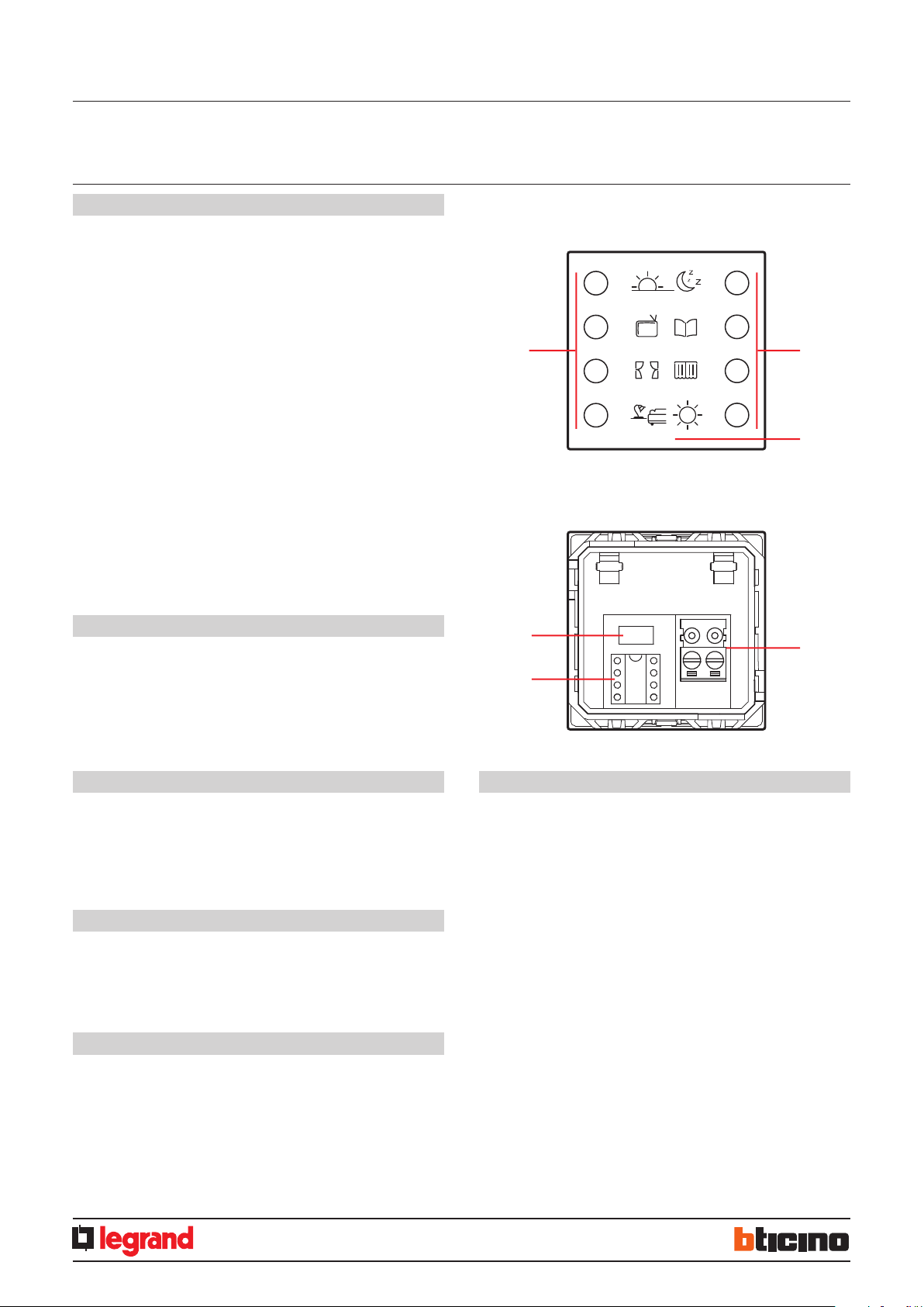
Description
Flush mounted multifunction control, with 8 backlit keys in the centre section, where
the icons indicating the functions allocated to the keys can be found.
The device can be configured in two different ways:
- Physical configuration, by inserting the configurators in the appropriate housings.
- Configuration using the MyHOME_Suite software, which can be downloaded from
the website www.homesystems-legrandgroup.com; this last type of configuration
has the advantage of offering many more options when compared with the physical.
configuration.
Irrespective of the mode implemented, an A/PL address must always be assigned to
the control.
In can be programmed in 4 operating modes:
- The self-learning mode (cyclical or non cyclical) gives the possibility of associating
to each key the majority of the typical controls of the automation, sound, and video
door entry (staircase lights, door lock, call to the floor, door lock and camera cycling)
systems, in addition to the auxiliary controls.
- The scenario mode gives the possibility of recalling, programming and deleting 8
scenarios of a scenario module.
- The swivelling mode gives the possibility of driving 4 light points of shutters in
succession (room or group).
- CEN mode gives the possibility of using the control together with scenario
programmer MH200N or MH201.
Related items
3541 - 0 675 95 A5 sheets with symbol customisations, BLACK
3542 - 0 675 96 A5 sheets with symbol customisations, WHITE
For the customisation of the sheets, it is possible to use the tool found in the
MyHOME_Suite configuration software, which can be downloaded from the website www.homesystems-legrandgroup.com.
Front view
Rear view
1
5
4
1
2
3
Technical data
Power supply from SCS BUS: 18 – 27 Vdc
Absorption: with LEDs Off: 5 mA
with LEDs On at 100%: 20 mA
Operating temperature: 0 – 40 °C
Standards, Certifications, Marks
EN 60669-2-1
EN 50491-5-1
EN 50428
Dimensional data
Size: 2 flush mounted modules
Legend
1. Kyes
2. Customisable labels
3. Clamps for connection to the SCS BUS
4. Configurator socket
5. Programming pushbutton for self-learning and scenario modes
EN
02/12/2013MM00778-a-
1
Page 2
8 key multifunction control
BUS SCS
0 675 92
H4652
LN4652
Physical configuration
A
PL
M
LED
A room
PL light point
M mode (see the dedicated section)
LED backlight setting
(see the dedicated section)
Configurator A
room address
Configurator PL
light point address
Configurator M
1) Self-learning mode M=0
This mode of operation gives the possibility of associating an individual control to any
key of the device. It is possible to create, delete or modify each control. The device
may be configured using any A/PL address already present in the system, or a unique
address not used by other devices.
Programming the keys
The procedure to associate each key to a different control is as follows:
1) Press and release the programming key on the back of the device; the backlighting
LEDs will flash slowly:
2) Press the key to program within 20 seconds: the LEDs start flashing much quicker,
indicating the activation of the programming mode;
3) Set the control to associate to the key using the controls and/or the corresponding
actuator; the LEDs will start flashing slowly;
4) At this point it is possible to repeat points 2 and 3 for all the keys, including those
that have already been associated, to change their association association;
5) Quickly press the programming pushbutton, or wait 20 seconds to exit the
programming procedure.
Cancelling the programming of the keys
1) Press and release the programming key; the backlight LEDs will flash slowly:
2) Within 20 seconds press and hold down for 4 seconds the key to cancel; from now
on the key cancelled will no longer activate any control until programmed again;
3) The LEDs come on at full power for 4 seconds, after which it will be possible to
repeat point 2 to cancel the programming of other keys;
4) Press and quickly release the programming pushbutton, or wait 20 seconds to exit
the programming procedure.
NOTE: To delete the programming of all the keys at the same time, press and quickly
release the programming key; the LEDs start flashing slowly; press and hold down
again for 10 seconds the pushbutton on the back: the LEDs come on for approximately
4 seconds, confirming the cancellation of all programming.
2) Non-cyclical self-learning mode M=6
This mode is a variation of the self-learning mode (M=0), where, however, the keys
never operate cyclically. Therefore, if for example the ON of an actuator or dimmer
is acquired, the pair of keys is automatically configured to switch on, or increase the
intensity level, for the left key, and switch off, or decrease the intensity level, for the
right key. If, on the other hand, a single function is learnt (e.g. recalling of a scenario),
the other key of the pair remains without function, or retains the previous function. The
device may be configured using any A/PL address already present in the system, or a
unique address not used by other devices.
3) Scenario module M = 1 – 2
This operating mode can only be used if the system includes a scenario module F420;
the matching is achieved by assigning to both the items the same address, identified
by A=0-9 and PL=1-9. The user can create, cancel, or modify the scenarios found in the
scenario module, and can recall them using the keys.
The procedure gives the possibility of saving up to 16 scenarios using two devices.
The following table shows the correspondence between the number of the scenario
saved in the scenario module, and the keys of the control in the possible configurations:
Key 1 Key 2
Key 3 Key 4
Key 5 Key 6
Key 7 Key 8
Key number M=1 M=2
Key 1 Scenario 1 Scenario 9
Key 2 Scenario 2 Scenario 10
Key 3 Scenario 3 Scenario 11
Key 4 Scenario 4 Scenario 12
Key 5 Scenario 5 Scenario 13
Key 6 Scenario 6 Scenario 14
Key 7 Scenario 7 Scenario 15
Key 8 Scenario 8 Scenario 16
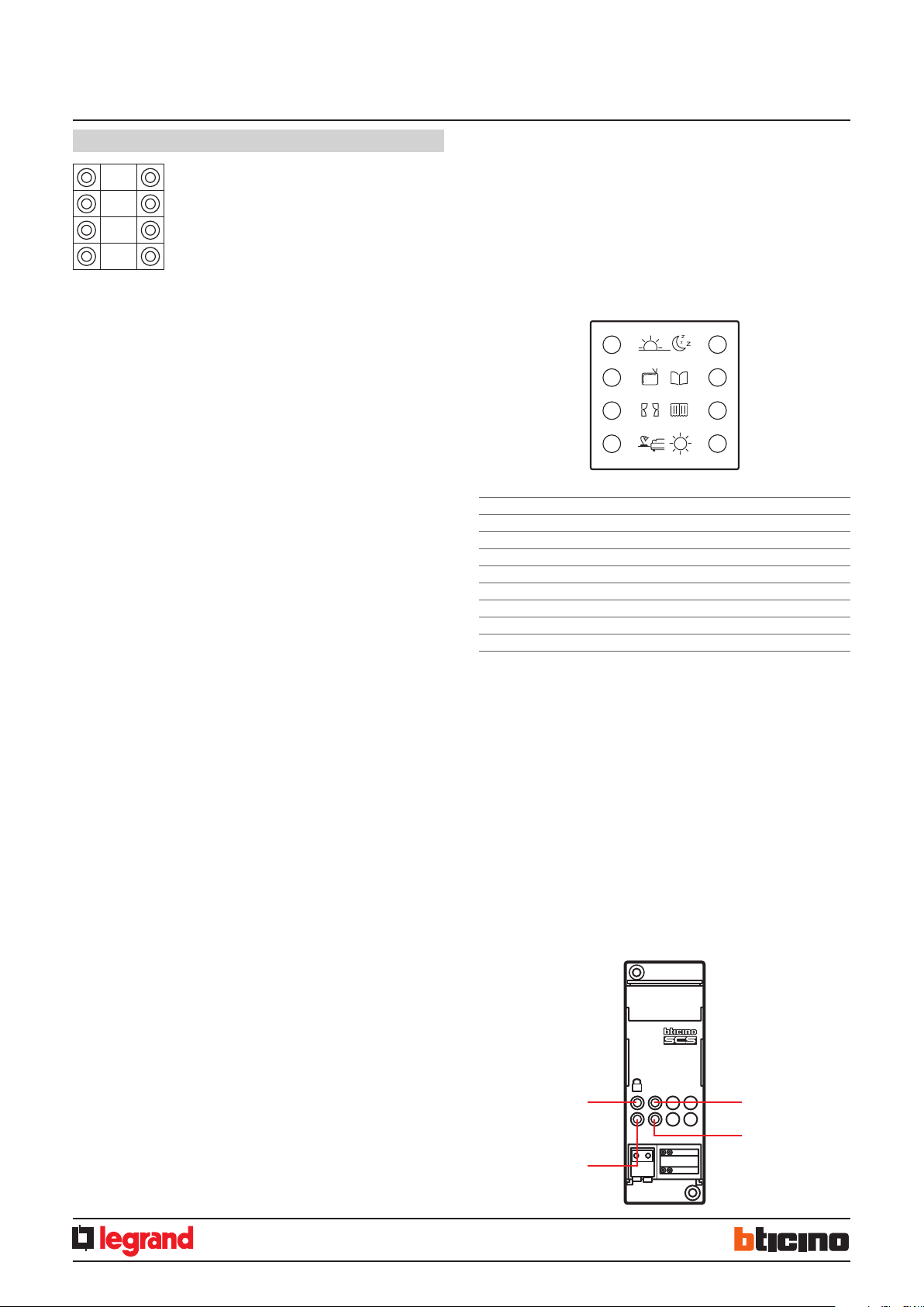
Programming a scenario with the F420 module
For the programming of the scenario, the procedure is as follows:
1) The F420 scenario module must be configured with self-learning enabled (it is
necessary to press the self-learning key so that the corresponding LED turns green; if
the LED is red, self-learning is disabled);
2) Press and release the programming key on the back of the multifunction control; the
LEDS start flashing slowly (1 sec. ON and 1 sec. OFF);
3) Within 20 seconds press the key corresponding to the scenario to program on the
multifunction control; its LEDs start flashing quickly, indicating the activation of the
programming mode;
4) Set the scenario, using the controls and/or actuators of the system;
5) Press the programming key of the multifunction control again to exit programming
and complete the procedure: the LEDs start flashing slowly again; it is now possible to
repeat points 2, 3, and 4 for all the scenarios; the same procedure must also be used to
change the scenarios already set;
6) Press and quickly release the self-learning pushbutton on the F420 module, or wait
20 seconds to complete the procedure (red LED on).
F420
ART.F420
programming block/
DEL
release key
programming status LED
scenario cancellation
key
scenario/learning
reset LED
EN
02/12/2013MM00778-a-
2
Page 3

8 key multifunction control
BUS SCS
0 675 92
H4652
LN4652
Deleting a scenario
To delete the scenario, the procedure is as follows:
1) The F420 scenario module must be in configuration mode with self-learning enabled;
2) Press and release the programming key of the multifunction control; the LEDS start
flashing slowly (1 sec. ON and 1 sec. OFF);
3) Within 20 seconds press and hold down for 4 seconds the key of the scenario to be
cancelled on the multifunction control;
4) The LEDs flash quickly for 4 seconds, after which it will be possible to repeat point 2 to
delete the other programming.
5) Press and quickly release the programming pushbutton on the back of the control, or
wait 20 seconds to exit the deleting procedure.
NOTE: to reset the whole memory, it will be necessary to directly act on the
scenario module: press “DEL” for ten seconds, after enabling the scenario module for
programming.
4) Swivelling modes M=0/I; ↑↓; ↑↓M
These modes ensure quick installation without the need for further learning, or
scenario modules, enabling the control of 4 light points or shutters with consecutive
addresses.
The A PL address is the light point or shutter controlled by the first pair of keys (the
keys are paired horizontally), the subsequent pairs controls the subsequent light points
or shutters.
If the Amb or Gr configurators are connected to A, in the same way, the 4 pairs of
keys control consecutive rooms or groups starting from the one indicated by the PL
configurator.
LED configurator
Setting the backlight intensity
The configurator in the LED housing gives the possibility of setting the backlight at the
desired level; see table:
LED configurator Brightness level
0 default setting = 30%
1 level 10 %
2 level 15 %
3 level 20 %
4 level 25 %
5 level 30 %
6 level 40 %
7 level 50 %
8 level 60 %
9 level 80 %
OFF level OFF
ON level 100 %
Possible function Value of M congurator
ON/OFF control: On control with the left key, O control
0/I
with the right key.
For point-to-point controls the key perform the On/O
function with a short pressure and
the adjustment with an extended pressure: for the other
controls, only On/O are performed
Control (UP/DOWN for shutters): up and down control,
↑↓
until fully open or closed
Monostable control (UP/DOWN for shutters): up and
↑↓M
down control, for the time the key is pressed
5) Scenario programmer mode, M=CEN
The matching between a scenario configured in the scenario programmer MH200N or
MH201, and the corresponding controls keys of the multifunction control, is completed
during the programming of the scenario itself using the dedicated software.
Always assign to the control a unique A/PL address on the system (it must not be
used by any other device installed on the BUS); the A=0, PL=0 configuration is not
acceptable. This operating mode can only be used if the system includes a scenario
programmer (MH200 or MH201).
Configuration using the software in a typical hotel system
This is performed using the appropriate MyHOME_Suite application. This mode has
the advantage of offering many more options when compared with the physical
configuration. The software configuration requires Ethernet connection between the
system and the PC, through the IP MH201 scenario module.
Ethernet connection to the system
Ethernet
network
HUB Switch
1
DC - In
2 345 6
Ethernet
network
MH201
MH201
BUS-SCS
EN
PC for room management
02/12/2013MM00778-a-
3
 Loading...