

LEGRAND Bticino HD4607/4, Bticino HC4607/4, Bticino N4607/4, Bticino L4607/4, Bticino NT4607/4 Quick Start Manual
...
1-4 zone transponder
divider
Description
This device is used to arm, disarm, and separate the zones of the system by placing a
transponder badge (item 3530S and item 3540 previously stored in the central unit) in
front of the zone transponder badge receiver.
When used in an automation system it performs the control function for the management
of scenarios.
By pressing one of the pushbuttons, the corresponding zone is armed/disarmed.
Within four seconds from the last pressure, the separation performed must be conrmed
by moving a transponder saved in the central unit close to the device.
Should this not take place, then the previous condition is automatically restored. Red LEDs
on indicate that the zones are active, whereas red LEDs o show that they are disarmed.
Technical data
- Power supply from SCS BUS: 27 Vdc
- Max. absorption: 15 mA
- Operating temperature: 5 – 40°C
Dimensional data
Size: 2 modules
HD4607/4
HC4607/4
1
7
6
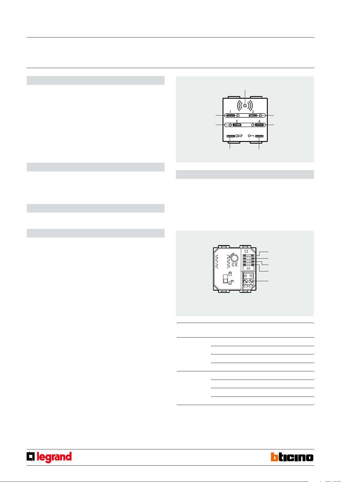
Front view
Legend
1 - Transponder badge receiver zone;
2 - LED and pushbutton for controlling of zone 2;
3 - LED and pushbutton for controlling of zone 4;
4 - Indication “System ON/OFF”;
5 - Alarm warning;
6 - LED and pushbutton for controlling of zone 3;
7 - LED and pushbutton for controlling of zone 1.
5
N4607/4
L4607/4
4
NT4607/4
AM5787/4HS4607/4
2
3
Conguration
BURGLAR-ALARM mode:
Since this item belongs to the activator group, it needs to be set up with the number of
the “group” assigned and the progressive number of the devices in the “group”. It can also
be programmed to perform Automation functions (scenario management).
See Automation “MY HOME” guide for details.
Z
This congurator assigns the number of the appropriate zone (from 1 to 8) in the “group”
of devices (any free zone in the system). To congure it as belonging to the activator
group, no congurator must be inserted.
N°
This congurator assigns the progressive number within the group of activators.
Congurator 1 identies the rst device, congurator 2 identies the second, and so
forth, up to a maximum of 9 activators (dividers, expanders or activators).
NOTE: If all 9 permitted devices have already been assigned to the activator group,
it could be possible to assign to congurator Z (zone it belongs to) a value between
1 and 9, taking into account the progressive number.
MOD
It assigns the modes of the audible signals (BEEP) and luminous signals (LED ON)
provided by the divider when controlled by the transponder; it is used as a activators/
disconnector of the “Burglar-alarm” system.
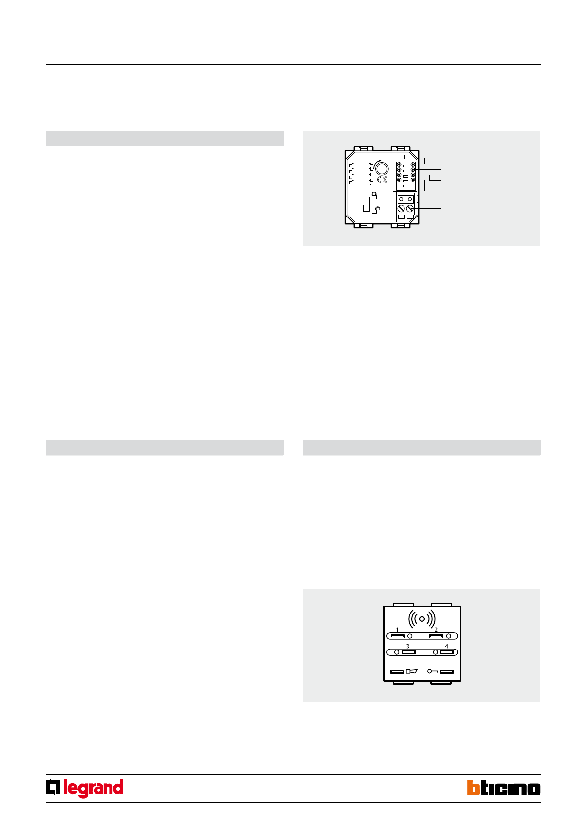
Rear view
Central unit
used
3486
3485/B
HD/HC/HS/L/N/
NT4601
L/N/NT4600/1
A/AM5780/1
=
1
02'
$8;
Congurator
value
none YES YES
1 NO YES
2 YES NO
3 NO NO
4 YES YES
5 NO YES
6 YES NO
7 NO NO
LED ON Enabling
Z
No.
MOD
AUX
Clamp for burglar
alarm BUS
BEEP
AUX
Position not congurable for the “Burglar-alarm” function; congure only if it is necessary
to enable the device for Automation functions (management of the scenarios stored in
the unit or scenario module).
MQ00028-c-EN 24/04/2014
1
1-4 zone transponder
divider
Conguration
AUTOMATION mode – SCENARIO MANAGEMENT:
Z
This congurator with value 0-9 coincides with the A position of the scenario module.
N°
This congurator with value 1-9 coincides with the PL position of the scenario module.
MOD
Assigns the operating mode. Connect congurator 9.
AUX
It assigns one of the scenarios programmed on the scenario module to the four
pushbuttons (SCE = 1-9) as per the table.
Pushbutton no. Associated scenario no.
pushbutton 1 SCE
pushbutton 2 SCE + 1
pushbutton 3 SCE + 2
pushbutton 4 SCE + 3
HD4607/4
HC4607/4
=
1
02'
$8;
N4607/4
L4607/4
Z
No.
MOD
AUX
Clamp for burglar
alarm BUS
NT4607/4
AM5787/4HS4607/4
Example
If congurator 3 is connected to AUX, use pushbutton 1 to recall scenario no. 3, pushbutton
2 to recall scenario no. 4, pushbutton 3 to recall scenario no. 5, and pushbutton 4 to recall
scenario no. 6
Pairing transponders
1.
Move the “programming block” switch to the open padlock and then:
2. Press pushbuttons 1 and 4 at the same time for more than 5 seconds until the alarm
LED status comes on for 0.5 second and an audible signal is heard.
3. Release pushbuttons 1 and 4.
4. Move the transponder being programmed close to the device:
- if the transponder has been correctly saved the alarm status LED will slowly ash
twice and an audible signal will be heard. Go to step 6.
- if the code is already in the memory there will be 2 audible signals and the led will
ash quickly twice.
- if the memory is full there will be 5 audible signals and the LED will ash quickly 5
times.
5. To store other transponders repeat the procedure in step 4, otherwise go to step 6.
6. Move the “programming block” switch back on the closed padlock to exit
programming. Otherwise the device will exit programming mode after 1 minute of
inactivity.
Erasing the memory
1. Move the “programming block” to the open padlock.
2. Press pushbuttons 1 and 4 at the same time for more than 10 seconds and check that
the LED ashes slowly 4 times, and that there is an audible signal.
3. Release pushbuttons 1 and 4.
4. The transponder zones activator will remain in programming mode, ready for a new
programming sequence.
5. Move the switch back to the closed padlock position to exit the erasing procedure.
MQ00028-c-EN 24/04/2014
2
 Loading...