

Page 1
MM00771
-a-EN
02/12/2013
1
BUS SCS
RFID key card switches
Description
RFID key card switch for the connection of the power supply to the hotel room
(13.56 MHz frequency key card detection). Thanks to the LED backlit slot, the device
can be found in the dark. An automatic switch off delay can also be set.
It can be used with key cards with sizes between 45 mm and 54 mm (ISO).
The device can be configured in two different ways:
- Physical configuration
- Configuration using the MyHOME_Suite software
the website www.homesystems-legrandgroup.com; this last type of configuration
has the advantage of offering many more options when compared with the physical
configuration.
Technical data
Power supply from SCS BUS:
Max. absorption: 6 mA
Stand-by absorption: 5 mA
Operating temperature:
RFID key card frequency:
Standards, Certifications, Marks
EN 60669-2-1
EN 50491-5-1
EN 50428
Dimensional data
Size: 2 flush mounted modules
, by inserting the configurators in the appropriate housings.
, which can be downloaded from
18-27 Vdc
5 – 40 °C
13.56 MHz
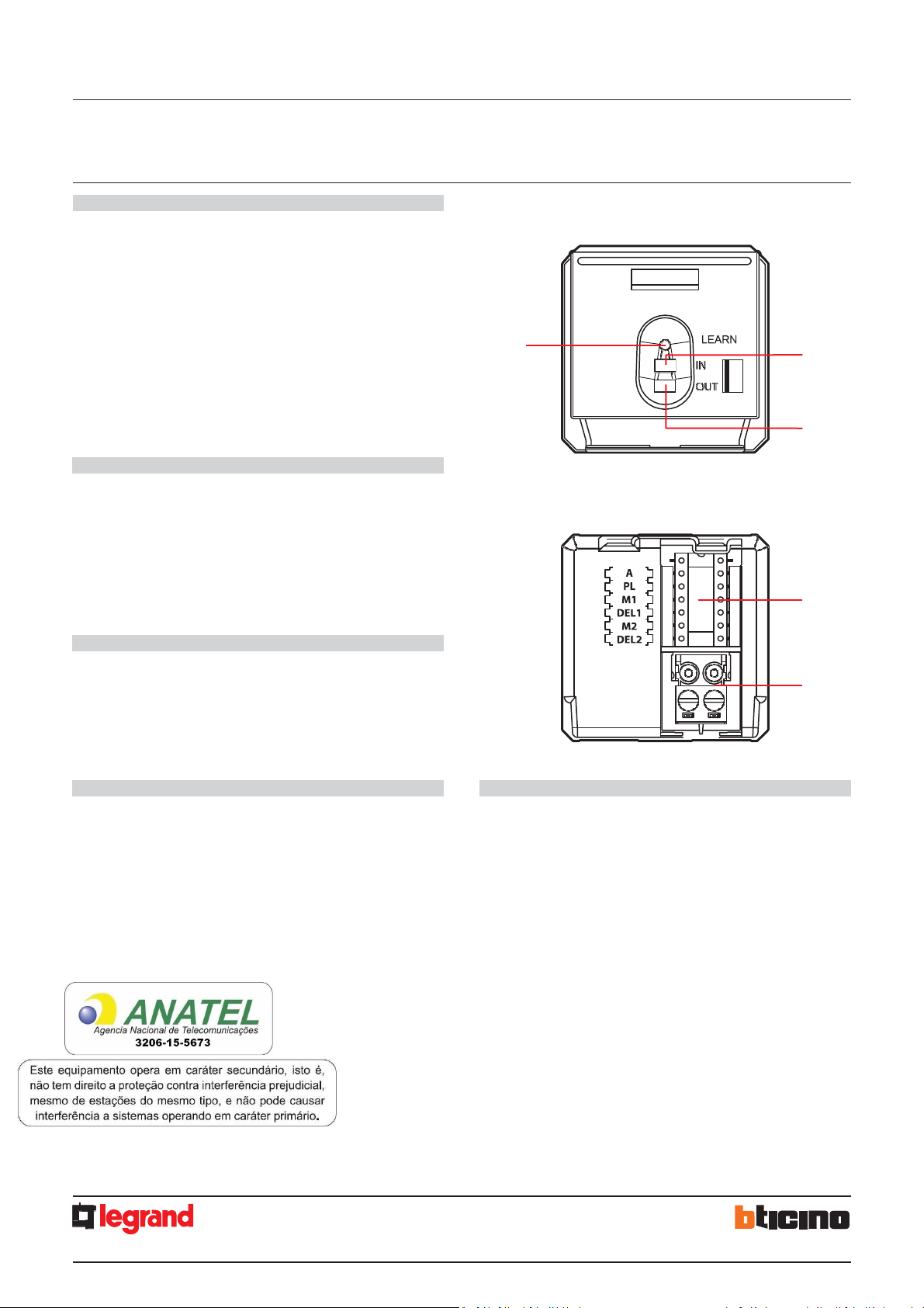
5
Front view
0 675 66
5 727 36
5 722 36
3
H4648
LN4648
1
2
Rear view
4
Legend
1.
2.
3.
4.
5.
Programming key: Learn IN
Programming key: Learn OUT
LED
Configurator socket
SCS BUS connector
Page 2
MM00771
-a-EN
02/12/2013
2
BUS SCS
MH201
Ethernet
network
HUB Switch
MH201
DC - In
Ethernet network
BUS-SCS
PC for configu ration
1 Scenario
-
group (Sce1=1, Sce2=9, Gr=1)
RFID key card switches
Physical configuration
Two modes:
- CENTRALIZED, to recall scenarios managed by the scenario programmer. When
the key card is inserted and removed, the device forwards a signal to the scenario
programmer, which depending on the scenarios set will activate the corresponding
functions programmed.
A = 1-9 (CEN command address)
PL = 1-9 (CEN command address)
M1 = CEN
DEL1 = no configurator
M2 = no configurator
DEL2 = no configurator
Note: the insertion of the key card corresponds to “Pushbutton 1” of the control, while
the removal of the key card corresponds to “Pushbutton 2” of the control
- SCENARIO, where by inserting the key card a group of actuators is enabled, and an
entrance scenario is activated (through the scenario module), and by removing the
key card an exit scenario is activated (through the scenario module), thanks to which
all the group actuators will switch off and then disable after a set time delay.
A = 1-9 (as scenario module)
PL = 1-9 (as scenario module)
M1 = 1-8 (activation of the corresponding scenario: see table B)
DEL1 = 0 - 9 (switching on time delay at the insertion of the key card: see table A)
M2 = no configurator
DEL2 = 0 - 9 (switching off time delay after the removal of the key card: see table A)
Table A
Configurator value
0
1
2
3
4
5
6
7
8
9
Time
0
1 min
2 min
3 min
4 min
5 min
10 min
15 min
15 sec
30 sec
Table B
Configurator value
Note: Sce 1 = scenario activated on insertion
Sce 2 = scenario activated on removal
Gr = group of actuators
Configuration using the MyHOME_Suite software
This is performed using the appropriate MyHOME_Suite application. This mode has
the advantage of offering many more options when compared with the physical
configuration. The software configuration requires Ethernet connection between the
system and the PC, through the IP MH201 scenario module.
2
3
4
5
6
7
8
Scenario-group (Sce1=2, Sce2=10, Gr=2)
Scenario-group (Sce1=3, Sce2=11, Gr=3)
Scenario-group (Sce1=4, Sce2=12, Gr=4)
Scenario-group (Sce1=5, Sce2=13, Gr=5)
Scenario-group (Sce1=6, Sce2=14, Gr=6)
Scenario-group (Sce1=7, Sce2=15, Gr=7)
Scenario-group (Sce1=8, Sce2=16, Gr=8)
Scenario - Group
H4648
LN4648
Ethernet connection to the system
0 675 66
5 727 36
5 722 36
1 2 3 4 5 6
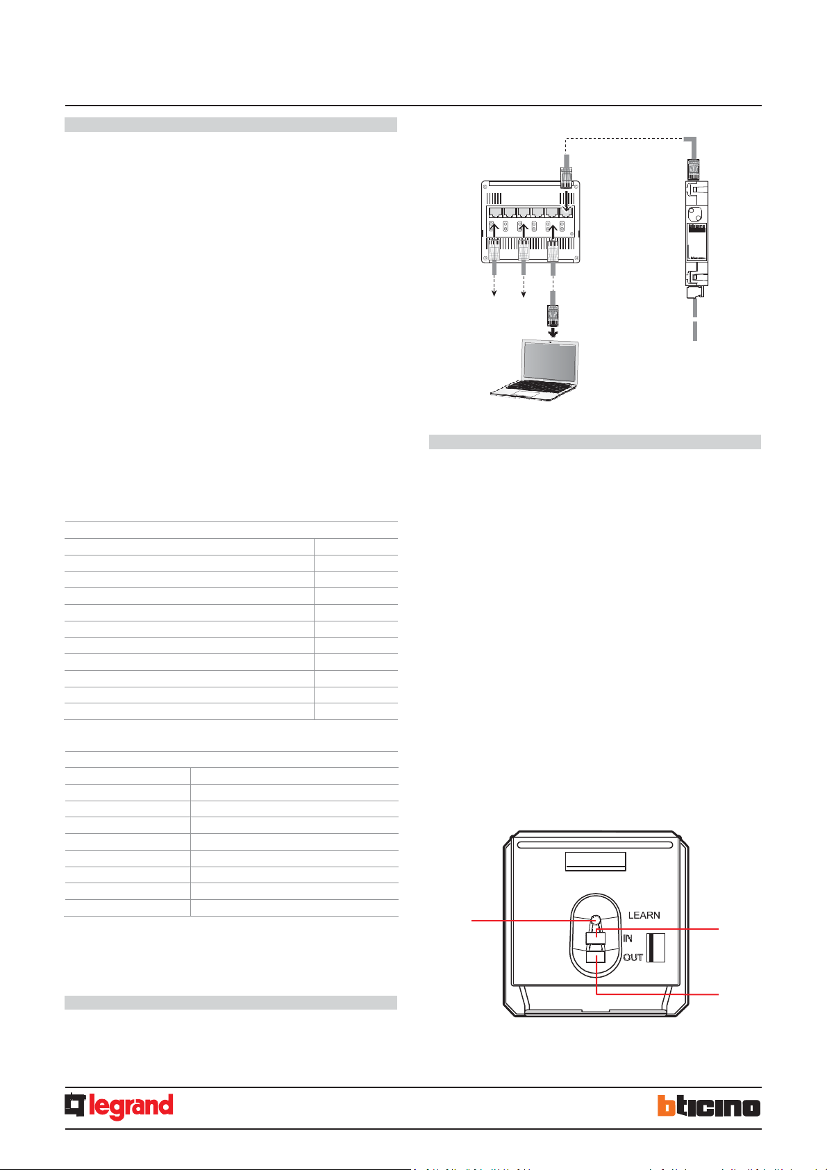
SCENARIO mode programming
SCENARIO mode programming
This operation is performed to create a link between the key card switch and the
scenario module. The procedure is as follows:
1) Power the key card switch. Check that the scenario module is in programming
mode, with the green LED on;
2) Press and hold down programming key 1 (Learn IN) or 2 (Learn OUT) until the LED
starts flashing (approximately 3 seconds);
3) Create the scenario using the system controls and actuators;
4) Once the scenario has been saved, briefly press programming key 1 (Learn IN) or 2
(Learn 2) to exit the programming status;
5) The scenario module will also have to exit programming status (see the scenario
module technical information).
Cancelling the programming in SCENARIO mode:
1) Power the key card switch. Check that the scenario module is in programming
mode, with the green LED on:
2) Press and hold down programming key 1 (Learn IN) or 2 (Learn 2) for 8 seconds.
after 3 seconds the LED will turn on, after a further 5 seconds it will turn off again;
3) Release the key;
4) The LED flashing, followed by the LED switching off, indicates that the programming
has been cancelled;
5) The scenario module will also have to exit programming status (see the scenario
module technical information).
3
1
2
1.
Programming key: Learn IN
2.
Programming key: Learn OUT
3.
LED
Page 3

3
BUS
SCS
RFID
k
e
y
c
a
r
d
swi
t
ches
0
675
66
5
722
36
H4648
LN4648
W
iring
diag
r
ams
MM00771
-
a
-
EN
02/12/2013
ZA = 2
ZB = 7
TYPE = 1
HEAT
= 7
PUMP = –
IN = 3
R1 = 2
R2 = 7
M
= 2
L
= 0
A
= 1
PL
= 1
T
= 2
A
= 9
PL
= 9
M1 = CEN
DEL1 = –
M2 = –
DEL2 = –
ITEM DESCRIPTION
E49 Power supply
Key card reader outside the door and
indicators
348210
Key card
LN4648
Key card switch
LN4653
DND and MUR controls
LN4652
8 key scenario control
LN4691
Thermostat with display
MH201
IP scenario module
F430R8
Air conditioning actuator
F411/1N
DIN module 1 relay actuator
The general switch GS (TM+EL) must
be selected based on the absorption of
the services installed.
The TM switch must be selected based
on the power supply used.
The TM switch must be selected based
on the loads connected.
The actuator
to be
used depends
on
installed.
If the current supplied by the E49
E46ADCN power supply.
HUB Swi tch
1
DC - In
Other rooms
PC fo r room management
12 Vac/dc – 230 Vac
Ethernet
network
2 3 4 5 6
230 Vac
max 1A
Ethernet
network
Bell
L
230 V L
50 Hz N
N
L
V1
V2
V3
TM3
Magnet
MODE
+
–
FAN
H4691
D
3513
COOL = C EN
H4652
LN4652
0 675 92
A = 9
PL = 8
M = CEN
LED = –
BUS SCS
To other
devices
TM2
TM1
A B C
GS (TM+EL)
MH201
MH201
PRI
E49
E49
PRI: 220 – 240 V~
185 – 175 mA
50/60 Hz
SCS: 27 Vdc
600 mA
F
To other
room services
SCS
Magnet Contact
Protectio n
line
WINDOW
CLOSED
WINDOW
OPEN
L1 L
Transformer
H4651
LN4651
0 675 91
348210
0 675 89
Transformer
F411/1N
electric lock
A = 1
Room door
2 sec.
H4648
LN4648
0 675 66
5 727 36
5 722 36
NC contact
ON
ECO
H4653
LN4653
0 675 93
DND MUR
R1 = 2
R2 = 7
M
= –
Contact
LN4691
0 674 59
PL = 1
M =
PUL
Heating
Cooling
F430R8
E
ZA = 2
ZB = 7
N = 1
LOAD = –
ROOM
CORRIDOR
RECEPTION
LN4651
General note: the devices listed in the legend are for
the LivingLight series.
A
B
C D
E
F
the type of air conditioning system
is not sufficient to power the SCS
system, it is possible to use the
To the fan-coil
or temperature
control system
N
P
rinciple
and
c
onfiguration
diagram
f
or
a
hot
el
room
5
727
36
 Loading...