

Page 1
Cat. No(s): 6 614 31/33/34/40
6 624 31/33/34/40
Technical data sheet: S000083090EN-2 Updated: 15/01/2015 Created: 17/06/2014
1/9
B65 LED
Emergency lighting units with LEDs
Standard: 6 614 31/33/34/40
Addressable LVS: 6 624 31/33/34/40
IP 65 - IK 07 emergency luminaires with LEDs
Class II: 0
Cat. No. Flux/
standby
STD/
LVS
Mode M
cons.
NM
cons.
Type of
battery
6 614 31 100 Im/1 hr STD M/NM 4 2 NiCd
6 614 33 200 Im/1 hr STD M/NM 4 2 NiCd
6 614 34 350 Im/1 hr STD M/NM 4 2 NiCd
6 614 40 100 Im/3 hrs STD M/NM 3 0.8 NiMH
6 624 31 100 Im/1 hr LVS M/NM 4 2 NiCd
6 624 33 200 Im/1 hr LVS M/NM 4.2 2 NiCd
6 624 34 350 Im/1 hr LVS M/NM 3 0.8 NiMH
6 624 40 100 Im/3 hrs LV S M/NM 3 0.8 NiMH
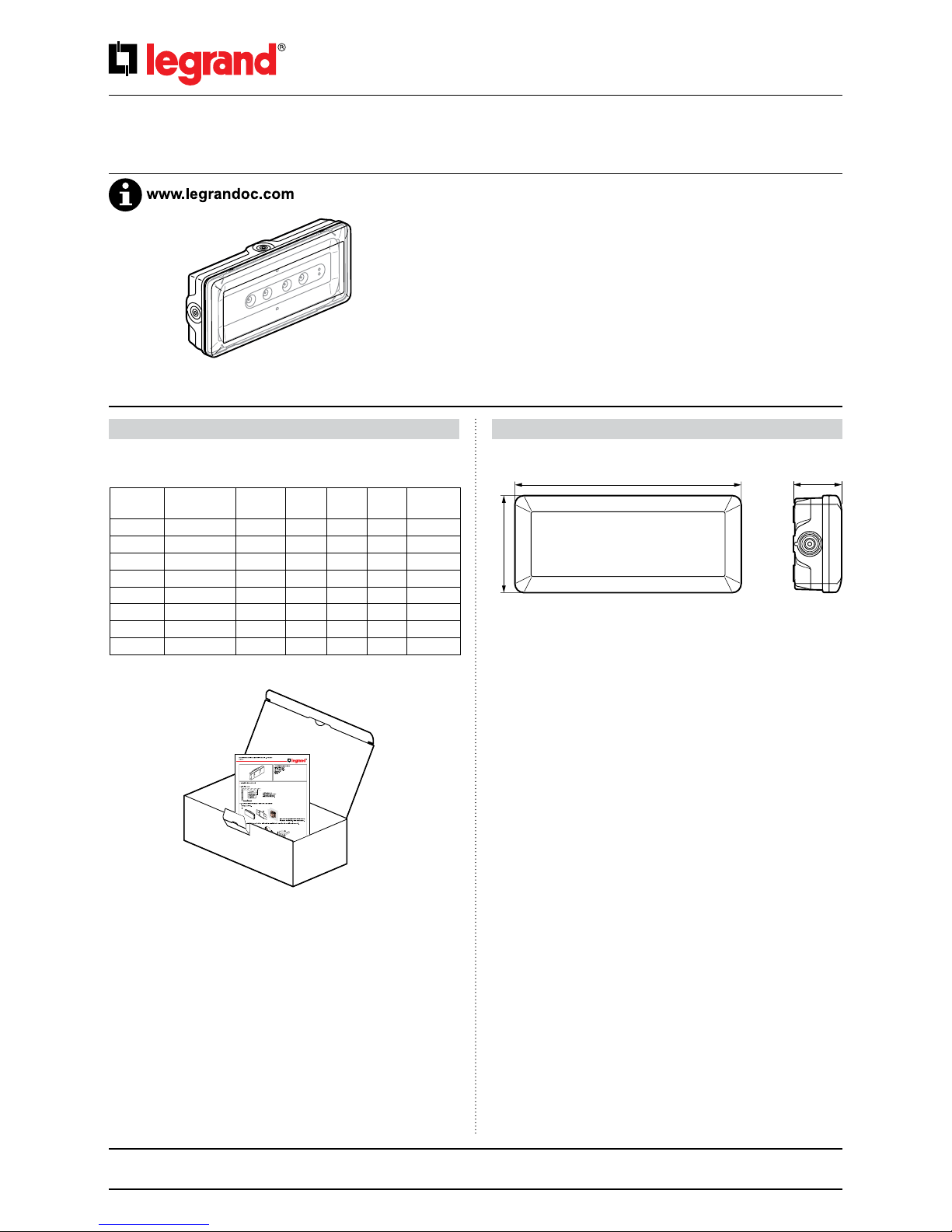
• Delivery
CONTENTS Page
1.
Description .
..................................................1
2.
Installation ....................
...............................2
3.
Operation .....................
...............................3
4.
Connection ....................
...............................4
5.
Addressing an
LVS luminaire with the configuration tool ......6
6.
Photometric data .
............................................8
7.
Maintenance ..
...............................................8
8.
Compliance and approvals ...................
.................9
9.
Accessories ....................
...............................9
1. DESCRIPTION
Weight of product in packaging: 700 grammes
Volume of product in packaging: 2.3 dm
3
• Dimensions
280
120
59.7
• Technical characteristics
230 V± - 50/60 Hz power supply
Fitted with large capacity automatic connection terminals (2 x 2.5 mm2)
Class II: 0
Operating temperature: 0°C to +40°C.
Remote control for setting to rest state during intentional mains power
breaks.
Remote control input terminals protected against errors of connection.
Terminal used to switch the maintained part of the light on and o in M/
NM units.
Complies with standards: EN 60598-2-22
Awarded the ENEC EN 60 598 2-22 and AENOR quality mark
Product for surface mounting on walls or ceilings.
1. DESCRIPTION CONTINUED
Page 2
2/9
Technical data sheet: S000083090EN-2 Updated: 15/01/2015 Created: 17/06/2014
B65 LED
Emergency lighting units with LEDs
Cat. No(s): 6 614 31/33/34/40
6 624 31/33/34/40
CONTENTS
1. DESCRIPTION CONTINUED 2. INSTALLATION CONTINUED
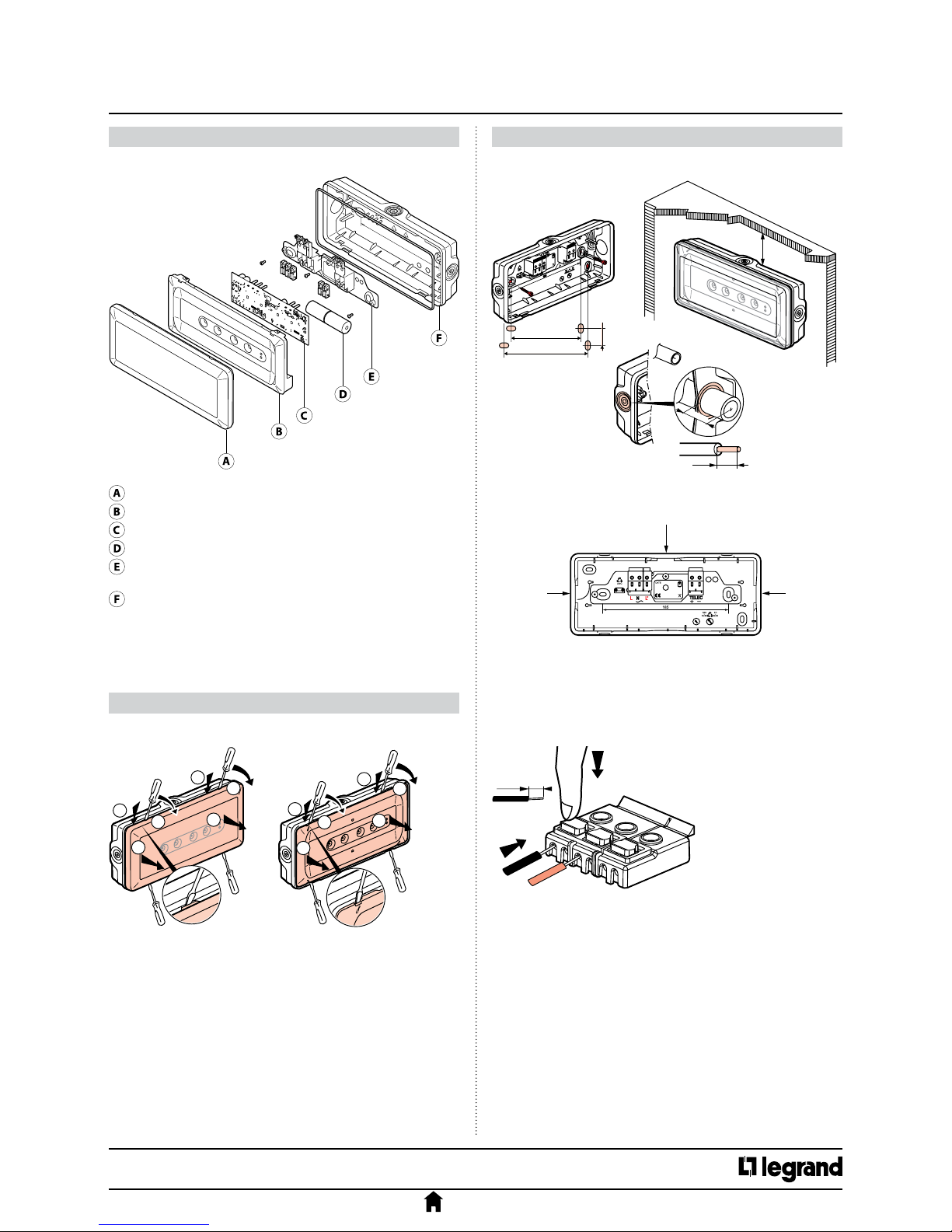
2. INSTALLATION
Diuser: self-extinguishing opal polycarbonate 750° 30 s
Reector: self-extinguishing white polycarbonate 850° 30 s
Electronic board
Battery
Terminal support plate: polypropylene
self-extinguishing 850°C 30 s
Removable base: polypropylene
self-extinguishing 850°C 30 s
All plastic parts weighing more than 50 g are marked with their material
type so that the materials can be recycled at the end of the life of the
product.
REMOTE CONTROL - Connection terminals: no polarity with the Legrand
remote control Cat. No. 0 039 00/01.
Terminal capacity: 2 x 2.5 mm
2
.
• Fixing
• Opening the unit
• Wiring
• If wiring with exible wires
Cable entr
y
Cable entry
Cable entr
y
12 mm
A
B
A
B
C
A
B
A
B
C
C
C
185
0
7
225
200 mm
Min
7 max
Ø 16/20/25 mm
10 max
• Materials
Page 3
3/9
Technical data sheet: S000083090EN-2 Updated: 15/01/2015 Created: 17/06/2014
B65 LED
Emergency lighting units with LEDs
Cat. No(s): 6 614 31/33/34/40
6 624 31/33/34/40
CONTENTS
3. OPERATION CONTINUED
3. OPERATION
2. INSTALLATION CONTINUED
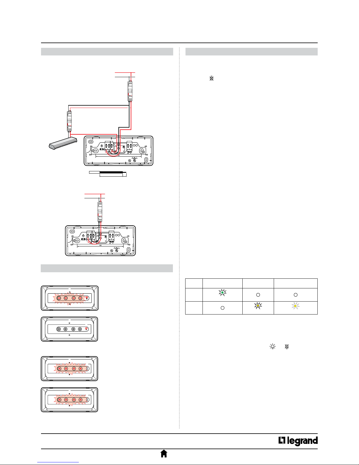
Maintained
The emergency LEDs come on
(ux -100 lumens) if terminal L' is
powered
Luminaire green status LED on
Maintained
The emergency LEDs come on
at rated ux
Luminaire green status LED goes o
Non-maintained
The emergency LEDs are o
Luminaire green status LED on
Non-maintained
The emergency LEDs come on
at rated ux
Luminaire green status LED goes o
• Wiring in maintained mode
• Wiring in non-maintained mode
3.1 Switch-on/standby state
3.2 Mains supply break/emergency operation
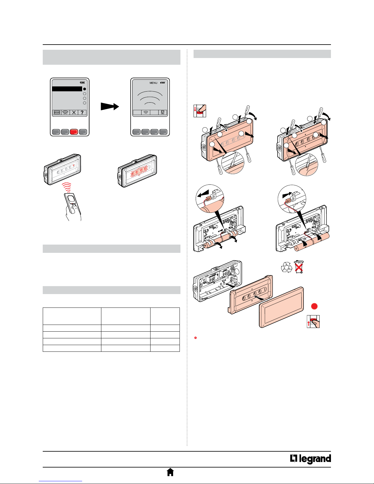
3.3 Setting to rest state via the remote control Cat. No. 0 039 00/01
After the normal lighting is switched o intentionally:
Pressing the
button sets the unit to rest state to prevent the battery
discharging.
Normal lighting switched back on:
The luminaire automatically returns to standby in the initial operating
mode (M/NM).
3.4 Testing standard luminaires
Standard luminaires can be tested by a normal power break:
- switch-on is veried correctly when the emergency LEDs are on
- standby power is veried correctly when the emergency LEDs stay on
throughout the rated standby power time (1 or 3 hours).
3.5 Testing LVS luminaires
LVS luminaires incorporate two operating modes: Self-test mode and
addressable mode.
Self-test mode
LVS luminaires are factory-congured in Self-test mode, and can
therefore be used in this mode without requiring any change of setting.
Addressable mode
This luminaire can also be used on an addressable system. For
this it must be addressed using the infrared conguration tool
Cat. No. 0 626 10 in accordance with the procedure described in section 6.
It then becomes possible to control it remotely using the control interface
Cat. No. 0 626 00 (for more detailed information, see the addressable
luminaires installation manual supplied with Cat. No. 0 626 00).
Lighting switch
1.5/2.5 mm
2
110 mm 12
Lighting main
circuit breaker
230 VA
L
N
LN
L’
Lighting switch
1.5/2.5 mm
2
110 mm 12
Lighting main
circuit breaker
230 VA
L
N
LN
Lighting main
circuit breaker
230 VA
L
N
L’
3.5.1 Automatic checking of the luminaire status (Self-test system)
This luminaire automatically checks its operating status.
This operating mode is only available for LVS luminaires.
Once a week:
Switches to emergency state for 15 seconds and tests switching to
emergency operation and the light sources.
Once every three months:
Switches to emergency operation for the rated standby power time (1 hr;
3 hrs) and tests the battery standby power.
3.5.2 Result of the automatic checks
The time of the tests is set at the time the luminaire is rst switched on.
The day of the test is chosen randomly in order to ensure that a minimum
number of luminaires is tested at the same time.
The time at which all the luminaires are tested can be changed to the
required time by simultaneously pressing the
and buttons on the
remote control.
3.5.3 Stopping a test in progress
If a standby power test hinders operation, it can be stopped immediately.
Press the OFF button on the remote control unit Cat. No. 0 039 00 or on the
control interface Cat. No. 0 626 00. The test is stopped and postponed until
the following day.
LEDs
Luminaire
OK
Battery
fault
Other
fault(s)
Green
(steady or flashing)
Yellow
(steady)
(rapid flashing)
Page 4

4/9
Technical data sheet: S000083090EN-2 Updated: 15/01/2015 Created: 17/06/2014
B65 LED
Emergency lighting units with LEDs
Cat. No(s): 6 614 31/33/34/40
6 624 31/33/34/40
CONTENTS
3. OPERATION CONTINUED
4. CONNECTION
4. CONNECTION CONTINUED
4.1 Connecting the mains power to the self-contained luminaires
The polarity of the remote control need not be followed on LVS luminaires
if a Legrand remote control Cat. No. 0 039 00 or 0 039 01 is used. If another
remote control is used, the polarity must be followed when wiring, and
the switch-on or switch-o command must be maintained for at least 2
seconds.
4.2 Connecting the remote control
Remote control for setting to rest state
The branch can be joined in the
electric cabinet, on the switch
or in a junction box.
The power supply to the
luminaires is subject to the
same rules as the luminaires
(normal wiring).
Lighting main
circuit breaker
Cat. No. 0 039 00
Remote control
circuit breaker
Lighting
circuit breaker
Normal lighting
switch
Luminaires
with LEDs
Luminaires
with LEDs
009300
230 VA
50 Hz
15 mA
Reinforced emergency light
3.5.4 Special cases
When the luminaire has been switched o for more than 3 days, the tests
are no longer carried out. The test cycle will resume after the luminaire
is switched back on and the batteries have been recharged. The tests
planned for the day the luminaire is switched back on are automatically
postponed for 24 hours.
Page 5

5/9
Technical data sheet: S000083090EN-2 Updated: 15/01/2015 Created: 17/06/2014
B65 LED
Emergency lighting units with LEDs
Cat. No(s): 6 614 31/33/34/40
6 624 31/33/34/40
CONTENTS
4. CONNECTION CONTINUED
4.3 Connection for an addressable installation for LVS luminaires (Cat. Nos. 6 624 31/33/34/40 only)
Installation with general setting to rest state
Installation with partial setting to rest state
250 luminaires and 2500 m of cable (1.5 mm2 max.) directly
connected to the control interface. Above this use a repeater
1023
luminaires
max.
Max. length of a line of luminaires: 700 m.
Above this length, place a repeater in series with
the following luminaires (4 repeaters max. cascaded)
230 VA mains supply
10 A
circuit breake
r
Control interface
Cat. No. 0 626 00
Repeater
Cat. No. 0 626 03
Repeater
Cat. No. 0 626 03
B1, B2:
Control units for setting
the establishment partly
to rest mode.
These control units have
no effect on the other
parts of the installation.
1 to 250 luminaires
Floor 2
Floor 1
0 039 00
0 039 00
0 626 03 0 626 03
0 626 03 0 626 03
Common
areas: corridors,
stairways, etc.
Common areas: entrance
to the building, etc.
1 to 250 luminaires
Control
interface
230 VA mains supply
0 626 00
10 A circuit
breaker
Page 6

6/9
Technical data sheet: S000083090EN-2 Updated: 15/01/2015 Created: 17/06/2014
B65 LED
Emergency lighting units with LEDs
Cat. No(s): 6 614 31/33/34/40
6 624 31/33/34/40
CONTENTS
5.1 Programming the address with the conguration tool loaded
using the interface conguration software
Adresses
Test adressage
Langue
Zones
AET2 (000/021)
ARDC (000/012)
BET1 (000/025)
AET1 (000/011)
Indicates the number of luminaires in the
zone and how many are addressed: here there
are 11 luminaires in this zone and 0 addressed.
Select the zone in which you wish to
addr
ess the luminaires.
The luminaire must be powered up.
Max. distance between remote control
and luminaire of 0.1 to 2 m.
AET2 -002
ARDC -003
BET1 -004
AET1 -001 ✓
ZONES
Explanation of the buttons:
Used to give the switch position for
switched luminaires.
Used to address the luminaire by standing
under it with the configuration tool (the
luminaire emergency LEDs come on for
2 seconds).
The luminaire must not already have an
address.
Used to delete addressing in a luminaire
with this address. Address 0000 is used to
delete addressing regardless of the unit
address (the emergency LEDs come on
twice for 2 seconds). This step is essential
when changing the luminaire address.
Used to test the addressed luminaire (the
luminaire emergency LEDs come on for
2 seconds to signal that the luminaire
contains the unit address and the standby
LEDs go off to signal that the luminaire
does not have the right address).
Turn on the configuration tool
by pressing OK for 2 seconds.
Select the Zones line in the
main menu
The luminaire has registered the
address, so its emergency LEDs
come on for 2 seconds.
5. ADDRESSING AN LVS LUMINAIRE WITH THE
CONFIGURATION TOOL CAT. NO. 0 626 10
5. ADDRESSING AN LVS LUMINAIRE WITH THE
CONFIGURATION TOOL CAT. NO. 0 626 10
Page 7

7/9
Technical data sheet: S000083090EN-2 Updated: 15/01/2015 Created: 17/06/2014
B65 LED
Emergency lighting units with LEDs
Cat. No(s): 6 614 31/33/34/40
6 624 31/33/34/40
CONTENTS
5.2 Programming a known address with the configuration tool
For example address 0000.
ADRESSES
Adresses
Test adressage
Langue
Zones
ADRESSES ADRESSES
Explanation of the buttons:
Used to address the luminaire by standing under it with the
configuration tool (the luminaire emergency LEDs come on for 2
seconds).
The luminaire must not already have an address.
Used to delete addressing in the luminaire with this address.
Address 0000 is used to delete addressing regardless of the unit
address (the emergency LEDs come on twice for 2 seconds). This
step is essential when changing the luminaire address.
Used to test the addressed luminaire (the luminaire emergency
LEDs come on for 2 seconds to signal that the luminaire contains
the unit address and the standby LEDs go off to signal that the
luminaire does not have the right address).
Max. distance between remote
control and luminaire of 0.1 to 2 m.
The luminaire has registered the
address, so its emergency LEDs
come on for 2 seconds.
5. ADDRESSING AN LVS LUMINAIRE WITH THE
CONFIGURATION TOOL CAT. NO. 0 626 10
5. ADDRESSING AN LVS LUMINAIRE WITH THE
CONFIGURATION TOOL CAT. NO. 0 626 10
5.3 Testing a particular address
If the address in the luminaire
is the addr
ess being tested,
its emergency LEDs come on
for 2 seconds.
5.4 Testing whether the luminaire is addressed
Adresses
Test adressage
Langue
Zones
ADRESSES
The luminaire has an address,
so its emergency LEDs come
on for 2 seconds.
AET2 -002
ARDC -003
BET1 -004
AET1 -001 ✓
ZONES
If the luminaire has another
address or no address, the
luminaire switches off its LED
indicator.
The luminaire does not have
an address, so it switches off
its LED indicator.
Max. distance between remote control
and luminaire of 0.1 to 2 m.
Page 8
8/9
Technical data sheet: S000083090EN-2 Updated: 15/01/2015 Created: 17/06/2014
B65 LED
Emergency lighting units with LEDs
Cat. No(s): 6 614 31/33/34/40
6 624 31/33/34/40
CONTENTS
6. PHOTOMETRIC DATA
7. MAINTENANCE CONTINUED
7. MAINTENANCE
The photometric data for all these luminaires are available in the Legrand
Dialux plug-in which can be obtained from the Legrand website.
7.1 Spare parts
7.2 Replacing the batteries
The batteries must be replaced when the self-contained luminaire no
longer works for its rated operating time.
Caution: this product must be switched o before dismantling.
OFF
0
I
Legrand distribution partners take back used luminaires and batteries.
When the batteries have been changed, replace the maintenance label,
marking on it the date on which the luminaire is returned to service.
• NB: The LEDs cannot be replaced
Luminaire Cat. No. Battery
Spare
battery
Cat. No.
6 614 31 2.4 V 1.5 Ah NiCd 0 610 92
6 614 33/6 624 31 3.6 V 1.5 Ah NiCd 6 609 72
6 614 34/6 624 33 4.8 V 1.5 Ah NiCd 6 609 62
6 614 40/6 624 34/6 624 40 4.8 V 2 Ah NiMH 6 609 71
A
B
A
B
C
A
B
A
B
C
C
C
ON
0
I
A
B
A
B
C
C
5. ADDRESSING A LUMINAIRE WITH THE
CONFIGURATION TOOL CAT. NO. 0 626 10 CONTINUED
5.5 Deleting the address of a unit
AET2 -002
ARDC -003
BET1 -004
AET1 -001 ✓
ZONES
The operation is registered, the
standby LEDs remain on and the
emergency LEDs come on twice.
Max. distance between remote control
and luminaire of 0.1 to 2 m.
11
Page 9

9/9
Technical data sheet: S000083090EN-2 Updated: 15/01/2015 Created: 17/06/2014
B65 LED
Emergency lighting units with LEDs
Cat. No(s): 6 614 31/33/34/40
6 624 31/33/34/40
CONTENTS
8. COMPLIANCE AND APPROVALS
9. ACCESSORIES
EN 60 598-2-22: European standard “Luminaires: specic rules. Luminaires
for emergency lighting”
EN 60 598-1: European standard “Luminaires”
EN 50172: European standard “Emergency escape lighting systems”
EN 1838: European standard “Lighting applications – Emergency lighting”
Products certied to the AENOR N quality mark
Electromagnetic eects: EMC
Emission
- EN 55015 (disturbance voltages)
- EN 61000-3-2 (measurement of harmonics) class C
- EN 55022 (radiated interference) class B
Immunity
- EN 61000-4-2 (electrostatic discharges) criterion B 4 kV (contact)
- EN 61000-4-3 (radiated elds) criterion A 10 V/m
- EN 61000-4-4 (fast transients/bursts) criterion B 4 kV on network and
1 kV by coupling
- EN 61000-4-5 (lightning impulses) criterion B
- EN 61000-4-6 (conducted disturbances) criterion A
- EN 61000-4-8 (magnetic elds) criterion A
- EN 61000-4-11 (voltage dips and short interruptions)
Self-adhesive legend plates
- Conforming to standard EN ISO 7010:
- Other suggested solutions:
6 616 70
6 616 70 6 616 70
6 616 71
6 616 71
6 616 72
6 616 72
6 616 80
EXIT
6 616 80
6 616 81
UITGANG
6 616 81
6 616 82
SALIDA
6 616 82
6 616 83
SALIDA DE
EMERGENCIA
6 616 83
6 616 84
IRTEERA
6 616 84
6 616 85
SORTIDA
6 616 85
6 616 86
SORTIE
6 616 86
6 616 87
SAĺDA
6 616 87
6 616 88
NO
EXIT
6 616 88
6 616 89
SIN
SALIDA
6 616 89
6 616 90
6 616 90
6 616 91
6 616 91
 Loading...