

Page 1
INSTRUCTION/INSTALLATION SHEET
1x11 Telecom Modules
301 Fulling Mill Road, Suite G
Middletown, PA 17057
Phone (800) 321-2343 / Fax (717) 702-2546
www.onqlegrand.com
IS-0011 REV. G
1. Introduction
The On-Q/Legrand 1x11
Telecom Modules provide a
structured method for
distributing telephone service
and wide area network data
service throughout the house.
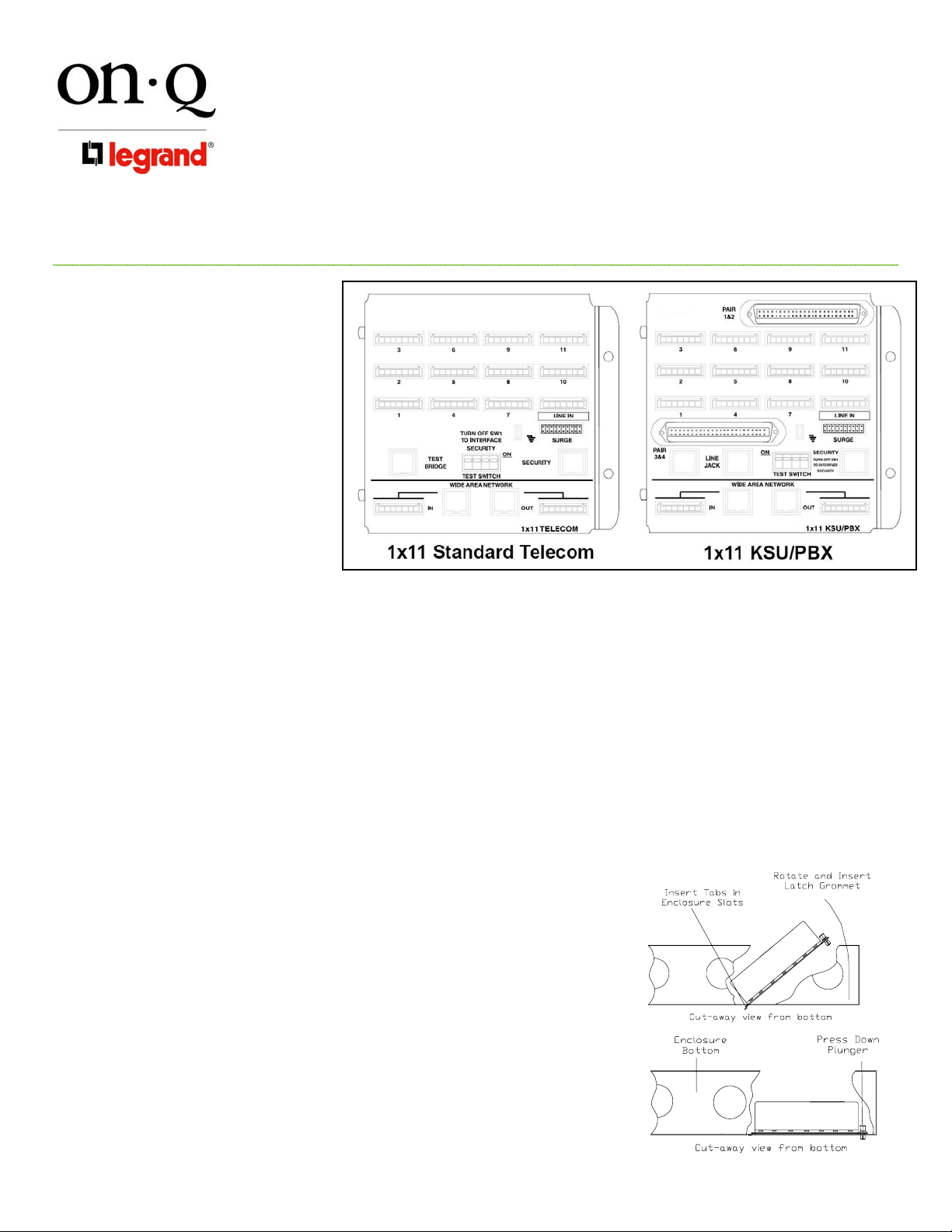
This instruction sheet covers the
1x11 Standard Telecom Module
(P/N 363484-01) and the 1x11
KSU/PBX Module (P/N 363485-
01) shown in Figure 1. The
modules can be directly
mounted in any On-Q style
enclosure.
2. Description
Both 1x11 Telecom Modules come with one 110-style punch down connector for connecting to the 4-line
incoming telecom service and eleven 110-style punch down connectors for connecting to the telecom outlets in
each room. Both modules also come with a 20-pin posted connector and spade terminal for an optional surge
protector (P/N 363487-01), an RJ-45 jack for test or local handset attachme nt, an RJ-45 jack for connection to an
RJ-31x security interface and a 4-position switch to allow separation of the incoming lines from the outlets for
testing purposes. Both modules also come with an identical WAN interface area with incoming and outgoing RJ45 jacks and 110-style punch down connectors. The 1x11 KSU/PBX Module also comes with two 50-pin style
telco connectors typically connected to KSU/PBXes or punch down blocks.
NOTE: This product is listed as UL 1863 – Communications Circuit Accessories and complies with
General Approval NS/G/1235/W/100025.
3. Installation
A. Mounting in enclosure (see Figure 2)
1) Align tabs on module with slots in enclosure.
2) Insert tabs by angling module away from the back of the enclosure
and sliding forward.
3) Rotate the module and insert fasteners on module into corresponding
holes in the enclosure. (Plunger must be in the pulled out position for
fastener to engage hole.)
4) Push plunger in to lock module in place. Pull on module to assure
module is locked properly in place.
B. Incoming Service Cable Installation (see Figure 3)
1) Route incoming service Cat 5e cable to “Line In” 110-style punch down
block, allowing slack for bundling, and cut cable about 2” past
connector.
Page 1 of 2
©Copyright 2008 by On-Q/Legrand All Rights Reserved.
on·Q on·Q
Figure 1
Figure 2
Page 2
INSTRUCTION/INSTALLATION SHEET
1x11 Telecom Modules
301 Fulling Mill Road, Suite G
Middletown, PA 17057
Phone (800) 321-2343 / Fax (717) 702-2546
www.onqlegrand.com
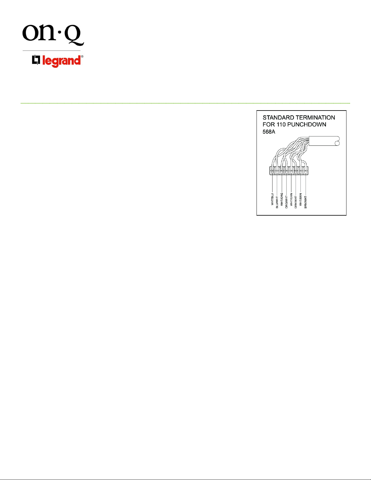
2) Strip off 4” of outer jacket and position pairs over color-coded slots of
connector (see Figure 3).
NOTE: Do not untwist pairs.
NOTE: White wires may npt have color trace stripe. Keep white wire
paired with appropriate colored wire based on twist.
3) Without untwisting cable, position the wires in the individual slots and
punch down and trim each wire (see Figure 3).
4) Remove any excess wire and tug lightly on the cable to insure a
secure punch down connection.
C. Outlet Cabl e Termination (see Figure 3)
1) Route outlet Cat 5e cables to numbered 110-style punch down
blocks, allowing slack for bundling, and cut each cable about 2” past
the associated connector.
2) Strip off 4” of outer jacket and position pairs over color-coded slots of
connector (see Figure 3).
NOTE: Do not untwist pairs.
NOTE: White wires may npt have color trace stripe. Keep white wire paired with appropriate
colored wire based on twist.
3) Without untwisting cable, position the wires in the individual slots and punch down and trim each wire
(see Figure 3).
4) Remove any excess wire and tug lightly on the cable to insure a secure punch down connection.
5) Record room name/number on wire layout label inside the enclosure.
D. Wide Area Network Cable Termination (see Figure 3)
1) Route incoming/outgoing WAN Cat 5e cable to “In/Out” 110-style punch down block in WAN area,
allowing slack for bundling, and cut the cable about 2” past the associated connector.
2) Strip off 4” of outer jacket and position pairs over color-coded slots of connector (see Figure 3).
NOTE: Do not untwist pairs.
NOTE: White wires may npt have color trace stripe. Keep white wire paired with appropriate
colored wire based on twist.
3) Without untwisting cable, position the wires in the individual slots and punch down and trim each wire
(see Figure 3).
4) Remove any excess wire and tug lightly on the cable to insure a secure punch down connection.
5) Complete the WAN Cable Termination by installing a Cat 5e jumper between the RJ-45 “In” jack and
“Out” jack.
E. Other Applications
1) RJ-31x Security Interface - Connect RJ-31x cable from security system to “Security” jack and place switch
#1 into the “off” position.
2) Surge Protection – For more details see instructions supplied with 363487-01.
3) PBX/KSU Wiring – For more details see instructions supplied with PBX/KSU Interface Kit (IS-0015).
IS-0011 REV. G
Figure 3
Page 2 of 2
©Copyright 2008 by On-Q/Legrand All Rights Reserved.
 Loading...