

Page 1
Operator’s Manual
WaveAce 1000/2000
Series Oscilloscopes
Page 2
WaveAce 1000/2000
Oscilloscopes
Operator's Manual
May, 2012
Page 3
LeCroy Corporation
700 Chestnut Ridge Road
Chestnut Ridge, NY, 10977-6499
Tel: (845) 578-6020, Fax: (845) 578 5985
Warranty
NOTE: THE WARRANTY BELOW REPLACES ALL OTHER WARRANTIES, EXPRESSED OR IMPLIED, INCLUDING BUT NOT LIMITED TO ANY IMPLIED
WARRANTY OF MERCHANTABILITY, FITNESS, OR ADEQUACY FOR ANY PARTICULAR PURPOSE OR USE. LECROY SHALL NOT BE LIABLE FOR ANY
SPECIAL, INCIDENTAL, OR CONSEQUENTIAL DAMAGES, WHETHER IN CONTRACT OR OTHERWISE. THE CUSTOMER IS RESPONSIBLE FOR THE
TRANSPORTATION AND INSURANCE CHARGES FOR THE RETURN OF PRODUCTS TO THE SERVICE FACILITY. LECROY WILL RETURN ALL PRODUCTS
UNDER WARRANTY WITH TRANSPORT PREPAID.
The oscilloscope is warranted for normal use and operation, within specifications, for a period of three years from shipment. LeCroy will either
repair or, at our option, replace any product returned to one of our authorized service centers within this period. However, in order to do this we
must first examine the product and find that it is defective due to workmanship or materials and not due to misuse, neglect, accident, or abnormal
conditions or operation.
LeCroy shall not be responsible for any defect, damage, or failure caused by any of the following: a) attempted repairs or installations by personnel
other than LeCroy representatives or b) improper connection to incompatible equipment, or c) for any damage or malfunction caused by the use of
non-LeCroy supplies. Furthermore, LeCroy shall not be obligated to service a product that has been modified or integrated where the modification
or integration increases the task duration or difficulty of servicing the oscilloscope. Spare and replacement parts, and repairs, all have a 90-day
warranty.
The oscilloscope's firmware has been thoroughly tested and is presumed to be functional. Nevertheless, it is supplied without warranty of any kind
covering detailed performance. Products not made by LeCroy are covered solely by the warranty of the original equipment manufacturer.
Internet: www.lecroy.com
© 2012 by LeCroy Corporation. All rights reserved.
Unauthorized duplication of LeCroy documentation materials other than for internal sales and distribution
purposes is strictly prohibited. However, clients are encouraged to distribute and duplicate LeCroy
documentation for their own internal educational purposes.
LeCroy, ActiveDSO, JitterTrack, WavePro, WaveMaster, WaveSurfer, WaveLink, WaveExpert, Waverunner, and
WaveAce are registered trademarks of LeCroy Corporation. Other product or brand names are trademarks or
requested trademarks of their respective holders. Information in this publication supersedes all earlier
versions. Specifications are subject to change without notice.
Manufactured under an ISO
9000 Registered Quality
Management System.
Visit www.lecroy.com to
view the certificate.
This electronic product is subject to disposal and
recycling regulations that vary by country and region.
Many countries prohibit the disposal of waste
electronic equipment in standard waste receptacles.
For more information about proper disposal and
recycling of your LeCroy product, please visit
www.lecroy.com/recycle.
WA1K2K-OM-E RevB
920673-00 RevB
Page 4

WaveAce 1000/2000
TABLE OF CONTENTS
Welcome ........................................................................ iv
Contact LeCroy for Support .......................................... iv
Thank You ..................................................................... iv
WaveAce 1000/2000 Models ........................................... 1
Safety Requirements ....................................................... 2
Safety Symbols ............................................................... 2
Operating Environment ................................................. 4
Safety Certification ........................................................ 4
Cooling ........................................................................... 5
AC Power Source............................................................ 6
Power Consumption ...................................................... 6
Power and Ground Connections .................................... 6
Fuse Replacement ........................................................... 8
(For Only WaveAce 2000 Models Only) ......................... 8
Calibration...................................................................... 8
Cleaning ......................................................................... 8
Abnormal Conditions ..................................................... 9
Hardware ..................................................................... 10
Front Panel ................................................................... 10
Back and Side Connections .......................................... 10
Basic Controls ............................................................... 12
Powering Up Your WaveAce ........................................ 12
Front Panel Controls .................................................... 13
Probes .......................................................................... 20
Probes .......................................................................... 20
Probe Compensation ................................................... 20
Page 5

Operator's Manual
ii WA1K2K-OM-E RevB
Viewing Waveforms ...................................................... 21
Turning On Traces ........................................................ 21
Setting Up the Display ................................................. 21
Understanding Display Information ............................ 22
Auto Setup ................................................................... 25
Vertical Settings and Channel Controls .......................... 27
Vertical Settings and Channel Controls ....................... 27
Choosing Coupling ....................................................... 27
Limiting Bandwidth ...................................................... 28
Adjusting Sensitivity ..................................................... 29
Setting Probe Attenuation ........................................... 30
Inverting Waveforms ................................................... 31
Setting the Digital Filter ............................................... 31
Unit and Skew Settings ................................................ 32
Acquisition Types .......................................................... 34
Acquisition Types ......................................................... 34
Zooming Waveforms ................................................... 37
Triggering ..................................................................... 39
Trigger Types ................................................................ 39
Edge Triggering ............................................................ 39
Pulse Triggering ........................................................... 40
Video Triggering ........................................................... 41
Slope Triggering ........................................................... 42
Alternative Triggering .................................................. 43
Analyzing Waveforms ................................................... 45
Analyzing Waveforms .................................................. 45
Measuring with Cursors ............................................... 45
Page 6

WaveAce 1000/2000
Parameter Measurements ........................................... 49
Waveform Math .......................................................... 55
FFT Spectrum Analyzer ................................................ 57
Creating Reference Waveforms ................................... 59
Save and Recall ............................................................. 62
Saving and Recalling Oscilloscope Settings .................. 62
Saving and Recalling Waveforms ................................. 64
Saving and Printing Waveform Pictures ...................... 66
Saving Data as a .CSV File ............................................ 68
Recalling Factory Settings ............................................ 70
Using the SAVE ALL Screen .......................................... 74
Utilities ......................................................................... 79
Utility Menu ................................................................. 79
Print Setup ................................................................... 88
Updating the System Software .................................... 90
Using Pass/Fail ............................................................. 93
Using Record ................................................................ 96
Setting and Displaying the Date/Time ....................... 100
Reference .................................................................... 102
Using WaveStudio ...................................................... 102
WaveAce Specifications ............................................. 105
Certifications .............................................................. 105
CE Declaration of Conformity .................................... 105
UL and cUL ................................................................. 107
China RoHS Compliance ............................................. 107
Contact LeCroy for Support ....................................... 109
Index ........................................................................... 113
Page 7

Operator's Manual
iv WA1K2K-OM-E RevB
Welcome
Thank you for purchasing a LeCroy WaveAce product. This Operator's Manual includes
important safety and installation information for your WaveAce 1000/2000 Oscilloscope,
along with operating procedures to get you started capturing, viewing, and analyzing your
waveforms.
This WaveAce Operator's Manual provides information in the following manner:
Get acquainted with your new instrument by reviewing topics covering Hardware
(explaining the physical features of your new instrument) and Basic Controls.
Viewing Waveforms includes instructions on setting up your display and using the
auto setup function.
The next sections provide information on Vertical Settings, Sampling Modes, and
Triggering.
Analyzing Waveforms lists waveform measurements and parameter
measurements. This section also provides procedures for using Math functions and
Creating Reference Waveforms.
Remaining sections cover step-by-step procedures for Saving and Recalling
oscilloscope setups, waveforms, .CSV files, and waveform pictures. This section also
provides procedures to recall factory settings. Finally, we provide a Reference
section including certification and contact information.
Contact LeCroy for Support
When your WaveAce 1000/2000 Oscilloscope is delivered, verify that all items on the
packing list or invoice copy have been shipped to you. Contact your nearest LeCroy
customer service center or national distributor if anything is missing or damaged. If you do
not contact us immediately, we cannot be responsible for replacement. If you have any
problems with your product, please refer to the Contact LeCroy for Support (on page 109)
topic at the end of this Operator's Manual. You can also refer to additional support
materials at www.lecroy.com, or the Online Help (located in the Help menu on your
instrument).
Thank You
We truly hope these materials provide increased comprehension when using LeCroy's fine
products.
Sincerely,
David C. Graef
LeCroy Corporation
Vice President and Chief Technology Officer
Page 8

WaveAce 1000/2000
WA1K2K-OM-E RevB 1
WaveAce 1000/2000 Models
WaveAce 1000/2000 models are available in two and four channel
versions. The following table shows the two and four channel models and
their rated bandwidths.
Two Channel WaveAce Models
Four Channel WaveAce Models
1001 - 40 MHz
1002 - 60 MHz
1012 - 100 MHz
2002 - 70 MHz
2012 - 100 MHz
2022 - 200 MHz
2032 - 300 MHz
2004 - 70 MHz
2014 - 100 MHz
2024 - 200 MHz
2034 - 300 MHz
Page 9

Operator's Manual
2 WA1K2K-OM-E RevB
Safety Requirements
This section contains information and warnings that must be observed to
keep the instrument operating in a correct and safe condition. You are
required to follow generally accepted safety procedures in addition to
the safety precautions specified in this section.
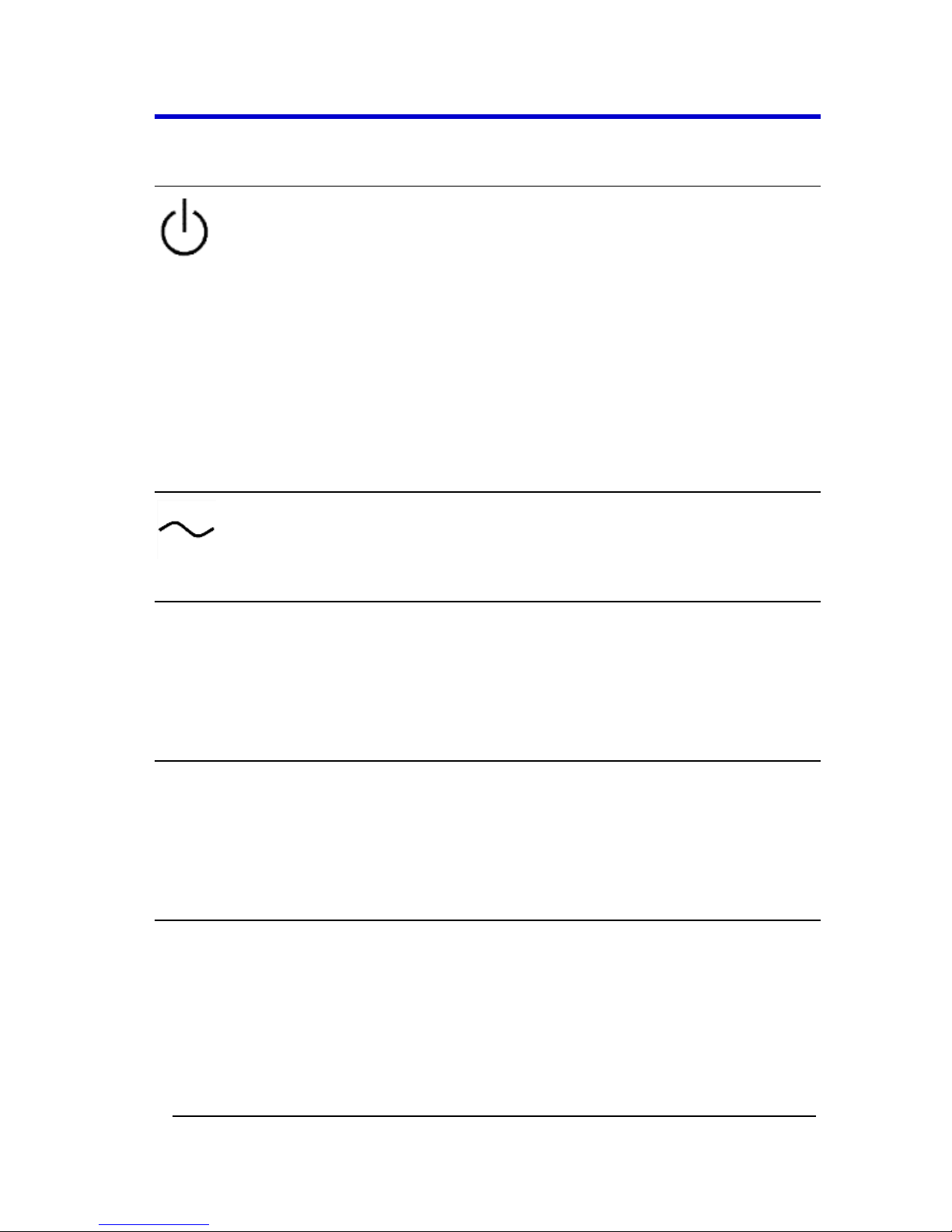
Safety Symbols
Where the following symbols appear on the instrument's front or rear
panels, or in this manual, they alert you to important safety
considerations.
This symbol is used where caution is required. Refer to the accompanying
information or documents in order to protect against personal injury or
damage to the instrument.
This symbol warns of a potential risk of shock hazard.
This symbol is used to denote the measurement ground connection.
This symbol is used to denote a safety ground connection.
On (Supply). This is the AC mains connect/disconnect switch at the back
of the instrument (if provided).
Page 10
WaveAce 1000/2000
WA1K2K-OM-E RevB 3
Off (Supply). This is the AC mains connect/disconnect switch at the back
of the instrument (if provided).
This symbol shows that the switch is a Standby (power) switch located on
the front of the oscilloscope. Pressing this button toggles the
oscilloscope's state between operating and Standby mode. This switch is
not a disconnect device. The instrument can only be placed in a complete
Power Off state by flipping the main power switch on the rear of the
instrument (if provided) to the off (Zero) position or by removing the
power cord. In cases where no main power switch is provided, removing
the main power cord is the disconnect device.
This symbol is used to denote Alternating Current.
CAUTION
The CAUTION sign indicates a potential hazard. It calls attention to a
procedure, practice or condition which, if not followed, could possibly
cause damage to equipment. If a CAUTION is indicated, do not proceed
until its conditions are fully understood and met.
WARNING
The WARNING sign indicates a potential hazard. It calls attention to a
procedure, practice or condition which, if not followed, could possibly
cause bodily injury or death. If a WARNING is indicated, do not proceed
until its conditions are fully understood and met.
CAT I
Installation (Overvoltage) Category rating per EN 61010-1 safety standard
and is applicable for the oscilloscope front panel measuring terminals.
CAT I rated terminals must only be connected to source circuits in which
measures are taken to limit transient voltages to an appropriately low
level.
Page 11
Operator's Manual
4 WA1K2K-OM-E RevB
Operating Environment
The instrument is intended for indoor use and should be operated in a
clean, dry environment. Before using this product, ensure that its
operating environment is maintained within these parameters:
Temperature: 10 to 40 °C.
Humidity: Maximum relative humidity 80 % for temperatures up to 31 °C
decreasing linearly to 50 % relative humidity at 40 °C (or at the upper
operational temperature limit).
Altitude: Up to 10,000 ft (3,048 m) at or below 25 °C.
Note: Direct sunlight, radiators, and other heat sources should be taken into
account when assessing the ambient temperature.
WARNING
The oscilloscope must not be operated in explosive, dusty, or wet
atmospheres.
CAUTION
Protect the oscilloscope's display touch screen from excessive impacts
with foreign objects.
CAUTION
Do not exceed the maximum specified front panel terminal voltage
ratings. Refer to Specifications for more details. The specifications for
maximum allowable voltages are located on a label on the front of the
oscilloscope.
Safety Certification
The design of the instrument has been verified to conform to applicable
EN 61010-1, UL 61010-1 2nd Edition and CSA C22·2 No·61010-1-04 safety
standards for the following limits:
Page 12

WaveAce 1000/2000
WA1K2K-OM-E RevB 5
Installation (Overvoltage) Categories II (Mains Supply Connector)
& I (Measuring Terminals).
Pollution Degree 2.
Protection Class I.
PLEASE NOTE THE FOLLOWING:
Installation (Overvoltage) Category II refers to local distribution
level, which is applicable to equipment connected to the mains
supply (AC power source).
Installation (Overvoltage) Category I refers to signal level, which is
applicable to equipment measuring terminals that are connected
to source circuits in which measures are taken to limit transient
voltages to an appropriately low level.
Pollution Degree 2 refers to an operating environment where
normally only dry non-conductive pollution occurs. Conductivity
caused by temporary condensation should be expected.
Protection Class 1 refers to grounded equipment, in which
protection against electric shock is achieved by Basic Insulation
and by means of a connection to the protective ground conductor
in the building wiring.
Cooling
The instrument relies on forced air cooling with an internal fan and
ventilation openings. Care must be taken to avoid restricting the airflow
around the apertures (fan holes) at the sides of the oscilloscope. Ensure
adequate ventilation by leaving the required 5 cm (2 inch) minimum gap
around the sides of the instrument.
CAUTION
Do not block the ventilation holes located on both sides of the
oscilloscope.
CAUTION
Do not allow any foreign matter to enter the oscilloscope through the
ventilation holes, etc.
Page 13

Operator's Manual
6 WA1K2K-OM-E RevB
AC Power Source
100 to 240 VAC (±10%) at 50/60/400 Hz (+10%); Installation Category:
300V CAT II
No manual voltage selection is required because the instrument
automatically adapts to line voltage.
Power Consumption
< 50 Watts for all models (depending on accessories installed - probes,
USB devices, etc.).
Power consumption in Standby Mode: < 5 Watts.
Power and Ground Connections
The instrument is provided with a 10A/250V 18AWG rated grounded
cord set containing a molded three-terminal polarized plug and a
standard IEC-60320 (Type C13) connector for making line voltage and
safety ground connections. The AC inlet ground terminal is connected
directly to the frame of the instrument. For adequate protection against
electrical shock hazard, the power cord plug must be inserted into a
mating AC outlet containing a safety ground contact.
WARNING - Electrical Shock Hazard
Only use the power cord provided with your instrument.
Any interruption of the protective conductor inside or outside of the
oscilloscope, or disconnection of the safety ground terminal creates a
hazardous situation. Intentional interruption is prohibited.
In Standby mode, the oscilloscope is still connected to the AC supply. The
instrument can only be placed in a complete Power Off state by flipping
the main power switch on the rear of the instrument (if provided) to the
off (Zero) position or by removing the power cord. In cases where no
main power switch is provided, removing the main power cord is the
disconnect device.
Page 14
WaveAce 1000/2000
WA1K2K-OM-E RevB 7
CAUTION
Always use the Power Switch or File → Shutdown command in the
software to properly shut down your instrument. Never substitute this
practice by pulling the instrument power cord from the socket or
shutting down a connected power strip.
CAUTION
The outer conductors of the front panel BNC terminals for all input
channels are connected to the instrument's chassis and therefore to the
safety ground.
Page 15

Operator's Manual
8 WA1K2K-OM-E RevB
Fuse Replacement
(For Only WaveAce 2000 Models Only)
Set the instrument Standby (power) switch to Standby mode, flip the
mains power switch to the OFF (0) position, and disconnect the power
cord before inspecting or replacing the fuse. Open the black fuse holder
(located at the rear of the instrument below the main power switch)
using a small, flat-bladed screwdriver. Remove the old fuse, replace it
with a new 5 X 20 mm T rated 1.25 A/250 V fuse, and reinstall the fuse
holder.
WARNING
For continued fire protection at all line voltages, replace fuse with the
specified type and rating only. Always disconnect the power cord before
replacing the fuse.
Calibration
The recommended calibration interval is one year. Calibration should be
performed by qualified personnel only.
Cleaning
Clean only the exterior of the instrument, using a damp, soft cloth. Do
not use chemicals or abrasive elements. Under no circumstances allow
moisture to penetrate the instrument.
Avoid electrical shock hazard by unplugging the power cord from the AC
outlet before cleaning.
WARNING - Electrical Shock Hazard
No operator serviceable parts inside.
Do not remove covers.
Refer servicing to qualified personnel.
Page 16

WaveAce 1000/2000
WA1K2K-OM-E RevB 9
Abnormal Conditions
Operate the instrument only as intended by the manufacturer.
If you suspect the oscilloscope's protection has been impaired,
disconnect the power cord and secure the instrument against any
unintended operation.
The oscilloscope's protection is likely to be impaired if, for example, the
instrument shows visible damage or has been subjected to severe
transport stresses.
Proper use of the instrument depends on careful reading of all
instructions and labels.
WARNING
Any use of the oscilloscope in a manner not specified by the
manufacturer may impair the instrument's safety protection.
Page 17
Operator's Manual
10 WA1K2K-OM-E RevB
Hardware
Front Panel
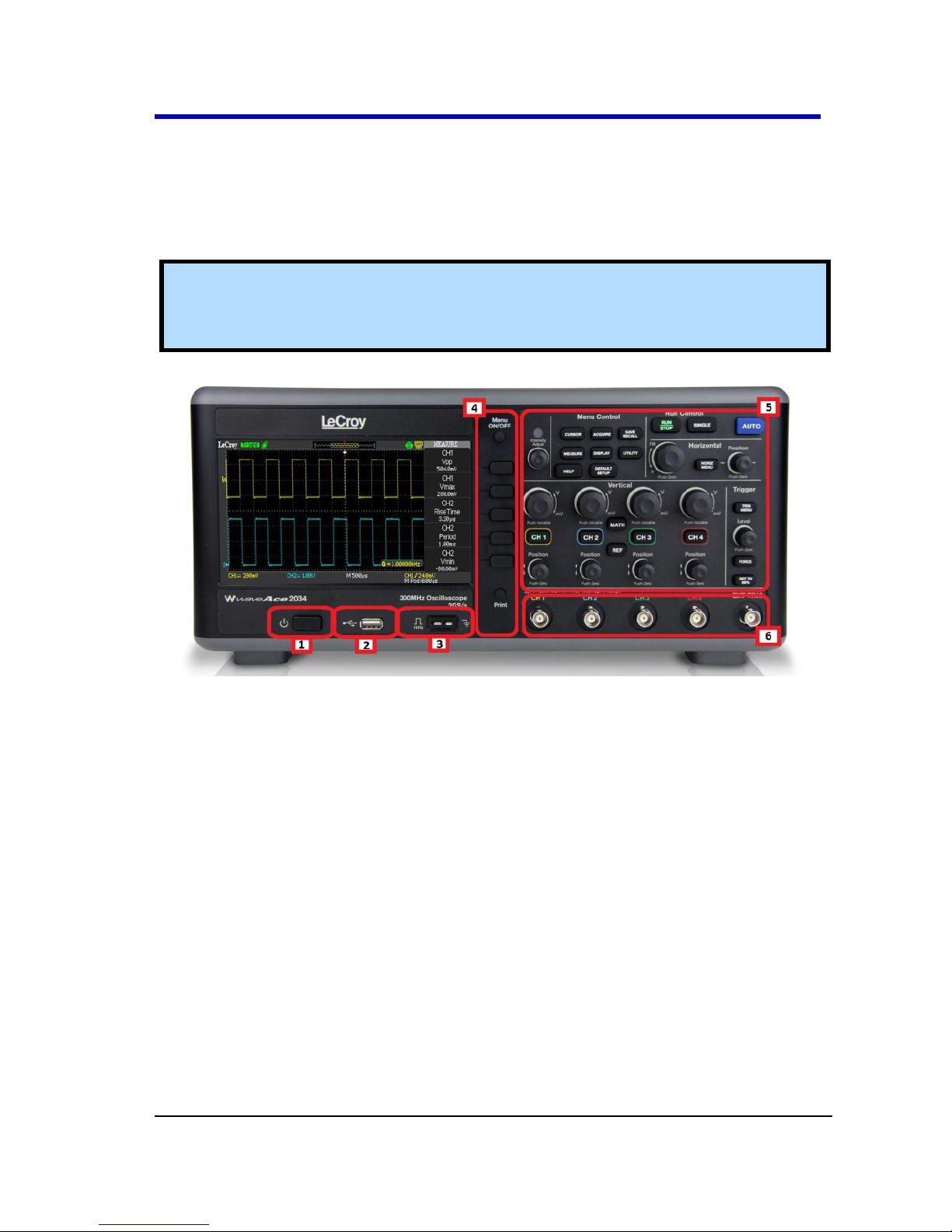
The WaveAce 1000/2000 Series oscilloscopes provide an easy-to-use
front panel. The control buttons are logically grouped.
Note: While the following picture is from the 4 Channel version, besides the
extra channels, button and knob locations are essentially the same on the 2
Channel model.
Front panel buttons and knob locations on 4 Channel WaveAce Oscilloscopes. Layout is
very similar on 2 Channel models
Previously numbered front panel buttons and knob locations correspond
with the following explanations.
1. Power Button
2. Front USB (Type A) Connector
3. 1 KHz and Ground Probe Connectors
4. Menu On/Off, Menu Option, and Print Buttons
5. Front Panel Controls
6. Channel and External Trigger Input Connectors
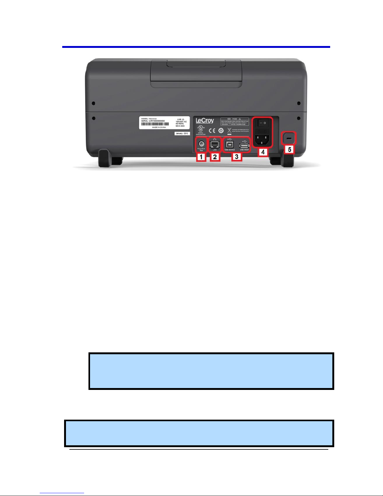
Back and Side Connections
The following image shows back panel connection locations for the 4
Channel models.
Page 18
WaveAce 1000/2000
WA1K2K-OM-E RevB 11
Back panel connection locations on the 4 Channel WaveAce Oscilloscope.
Previously numbered front panel buttons and knob locations on 4
Channel models correspond with the following explanations.
1. Pass/Fail Output
2. RJ-45 Connector
PLEASE NOTE THE FOLLOWING:
Contact a system administrator when connecting to any
internal LAN.
Use your WaveAce oscilloscope remotely by referring to
Using WaveStudio to Remotely Connect to your WaveAce
Oscilloscope (on page 102).
3. Rear USB (Type B and Type A, respectively) Connectors. Use the
Type B connector to attach a printer to your instrument. The Type
A connector is designated for memory stick use just like the one
on the Front Panel (on page 10).
Note: If you simultaneously connect separate memory sticks to both
the front and back Type A connectors, the WaveAce defaults to only
using the one attached to the front connector.
4. Power Shutoff Switch and Input Connector
5. Security Lock Receptacle
Note: The WaveAce 1000 model has a Power Input Connector and no Power
Shutoff Switch on the left side (facing) of the instrument instead of the back.
Page 19
Operator's Manual
12 WA1K2K-OM-E RevB
Basic Controls
Powering Up Your WaveAce
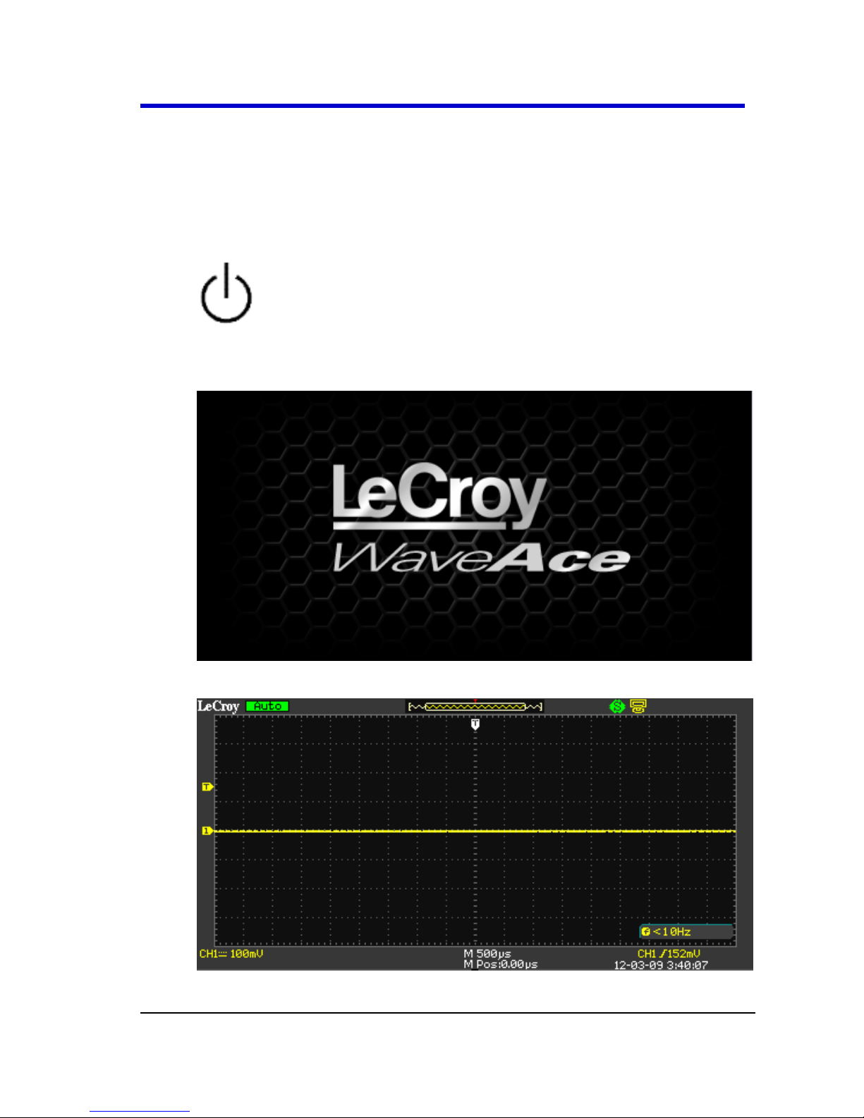
1. Power On the oscilloscope by pressing the power button (located
on the lower front of the 2000 models and top left on the 1000
models, when facing the instrument).
2. The LeCroy Splash screen is shown. Press any key to continue (or,
after a brief period the grid display is shown).
3. The Grid Display is shown.
Page 20
WaveAce 1000/2000
WA1K2K-OM-E RevB 13
Note: The screen size varies slightly between all WaveAce Series
Oscilloscopes. Therefore, the screen-shots in this documentation may
look more narrow or wide than they appear on your specific model.
However, the screens are all functionally the same and the slight
differences have no affect when following these instructions.
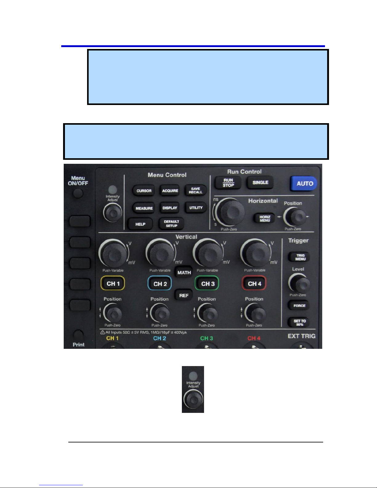
Front Panel Controls
Note: While the following pictures are from the 4 Channel version, besides the
extra channels, button and knob locations are essentially the same on the 2
Channel model.
Intensity/Adjust Knob
Intensity/Adjust knob - You can use the Adjust knob with many
functions, such as adjusting the holdoff time, moving cursors,
Page 21
Operator's Manual
14 WA1K2K-OM-E RevB
setting the pulse width, setting the video lineage adjusting the
upper and lower frequency limits, adjusting X and Y masks when
using the Pass/Fail function, etc. You can also turn the Adjust knob
to adjust the storage position of setups, waveforms, pictures when
saving/recalling and to select menu options.
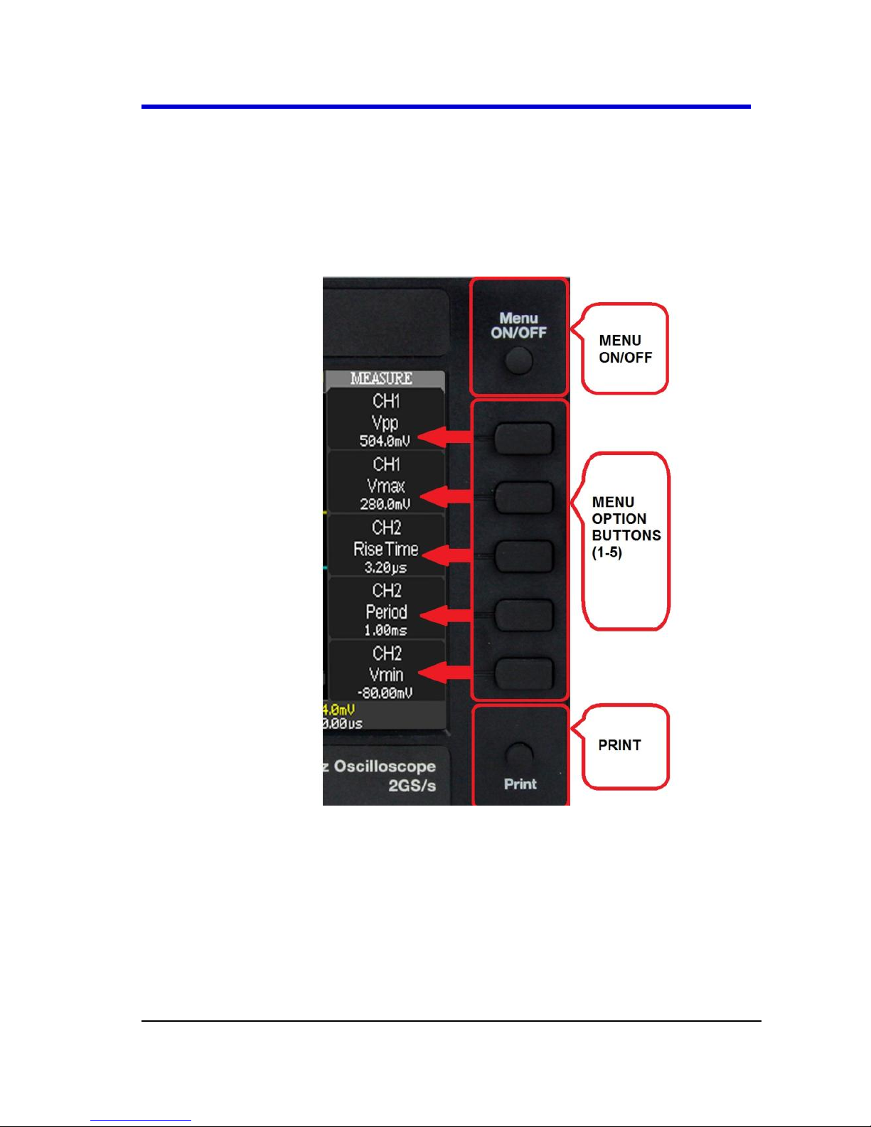
Menu Control, Option and Print Buttons
MENU ON/OFF - Press to toggle the last-displayed menu On/Off.
Menu Option buttons (1-5) - Press to choose menu options. Press
a menu option button adjacent to your selection.
Print - Press to save the current waveform to an attached USB
memory device or print a picture (screen shot) to a USB-connected
printer. You can set up the save/print options using the
Save/Recall → Picture settings. For more information, refer to
Saving and Printing Waveform Pictures (on page 66).
Page 22
WaveAce 1000/2000
WA1K2K-OM-E RevB 15
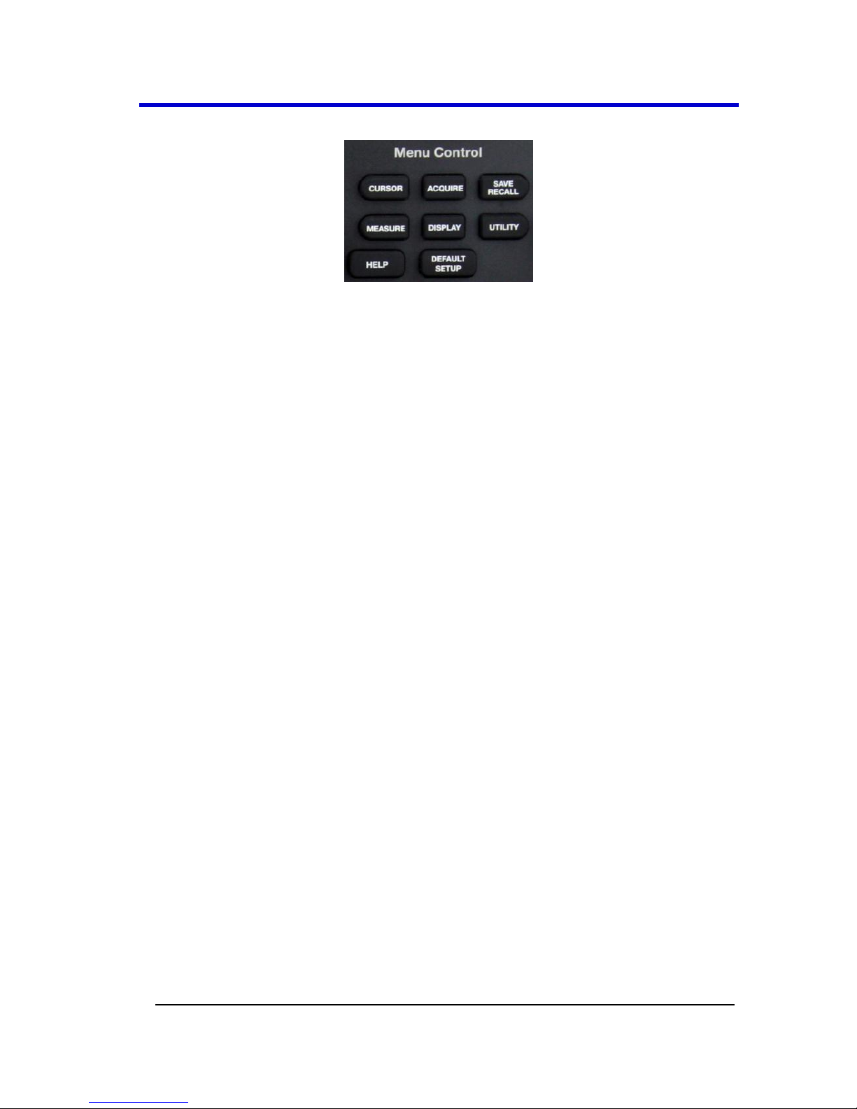
Menu Control Buttons
CURSORS - Press to turn on the cursors and display the Cursor
menu. You can use the Cursor menu to set the Cursor Mode
(Auto, Off, Manual, Track). When Cursors are on (CURSORS
button is lit), turn the Adjust knob to position the cursors. See
Measuring with Cursors (on page 45) for more information.
ACQUIRE - Press to display Acquire menu. You can use the Acquire
menu to set the acquisition Sampling Mode (Sampling, Peak
Detect, Average). See Acquisition Types (on page 34) for more
information.
SAVE/RECALL - Press to display the Save/Recall menu. You can
use the Save/Recall menu to save and recall up to 20 oscilloscope
setups or waveforms in internal memory (up to 20 waveforms) or
on a USB memory device (limited by memory capacity of USB
device). You can also use it to recall the default factory settings, to
save waveform data as a comma-delimited file (.CSV), and to save
or print the displayed waveform image. See Saving and Recalling
Oscilloscope Settings (on page 62) for more information.
MEASURE - Press to display a menu of measurement parameters.
The Display Type must be set to YT mode. For more information
on measurement parameters, refer to Parameter Measurements
(on page 49).
DISPLAY - Press to open the Display menu. You can use the
Display menu to set grid and waveform display styles, and
persistence. See Setting Up the Display (on page 21) for more
information.
UTILITY - Press to open the Utility menu. You can use the Utility
menu to configure WaveAce features, such as sound, language,
counter, etc. You can also view system status and update
software. See Utility Menu (on page 79) for more information.
Page 23
Operator's Manual
16 WA1K2K-OM-E RevB
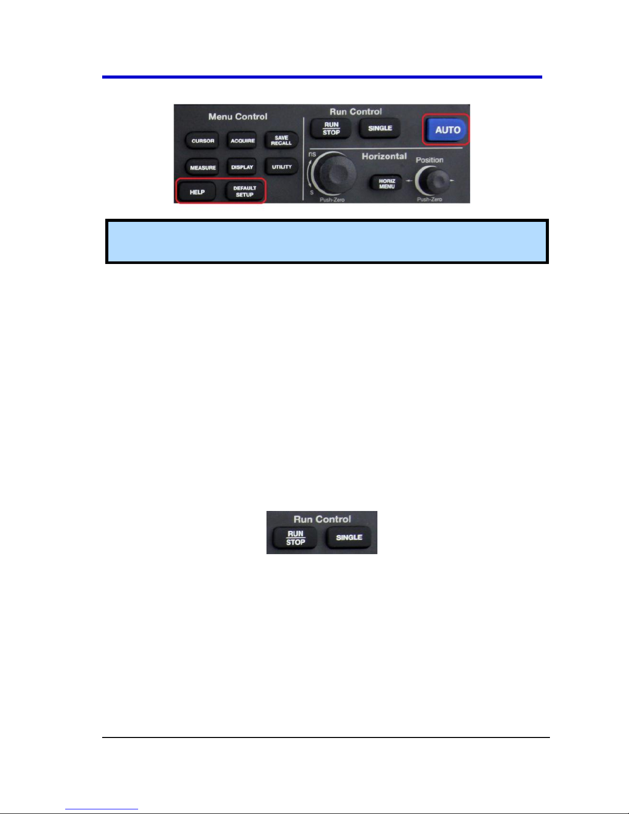
General Control Buttons
Note: Exact Help, Default Setup, and AUTO button locations vary on 4 and 2
Channel models.
HELP - Displays context-sensitive online help. Press Help, and then
another front panel button and information pertaining to the
selected button is shown.
DEFAULT SETUP - Press to reset the oscilloscope's settings to the
default factory configuration. For a list of default settings, see
Recalling Factory Settings (on page 70).
AUTO - Press to have the oscilloscope automatically identify the
type of waveform and adjust the controls to produce a usable
display of the input signal. When you press the AUTO front panel
button, the Auto Set menu opens. You can use this menu to
display multiple-cycle signals, a single-cycle signal, the rising edge,
the falling edge or recall the previous setup.
Run Control Buttons
SINGLE - Press to acquire a single waveform. Each time you press
the SINGLE button, the oscilloscope acquires another waveform.
When the oscilloscope detects a trigger it completes the
acquisition and stops.
RUN/STOP - Press when you want the oscilloscope to acquire
waveforms continuously. Press RUN/STOP again to stop the
acquisition.
See the Acquiring Waveforms section of Acquisition Types (on page 34)
for more information.
Page 24
WaveAce 1000/2000
WA1K2K-OM-E RevB 17
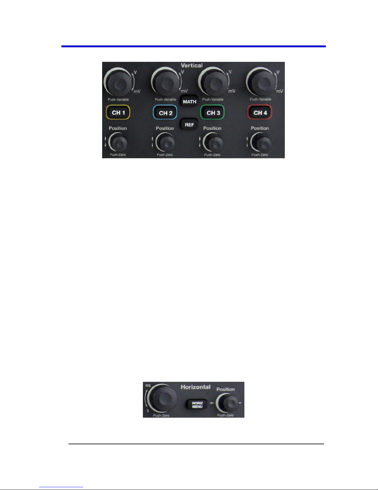
Vertical Controls
Volts/Div knobs (CH1-4, pictured) - Turn to adjust the
volts/division setting (vertical gain) of the corresponding channel
(CH1-4). Press the knob to toggle between fine (variable) and
coarse (fixed) adjustments. See Vertical Settings and Channel
Controls (on page 27) for more information.
Channel buttons (CH1-4) - Press a channel button (CH1-4) to turn
that channel ON or OFF and open the Channel menu for that
channel. You can use the Channel menu to set up a channel. When
the channel is ON, the channel button is lit.
Vertical Position knobs (CH1-4) - Turn to adjust the vertical
position of the corresponding channel (CH1-4). Press to set the
vertical position to zero.
REF - Press to display the Ref Wave menu. You can use this menu
to save and recall two reference waveforms (REFA and REFB) in
internal memory. See Creating Reference Waveforms (on page
59) for more information.
MATH - Press to display the Math menu. The Math menu provides
numerous mathematical functions as explained in Waveform
Math (on page 55).
Horizontal Controls
Horizontal Position knob - Turn to adjust the horizontal position
of all channels and math waveforms (the position of the trigger
Page 25
Operator's Manual
18 WA1K2K-OM-E RevB
relative to the center of the screen). The resolution of this control
varies depending on the timebase setting. Press to set the
horizontal position to zero.
HORI MENU - Press to display the Horizontal menu. You can use
the Horizontal menu to display the waveform and to zoom a
segment of a waveform.
Time/Div knob - Turn to change the horizontal time scale to
magnify or compress the waveform. When Window Zone is
enables, it changes the width of the Window Zone by changing the
window timebase. When the Time/Div control is set to 100 ms/div
or slower and the trigger mode is set to Auto, the oscilloscope
enters the scan acquisition mode. In this mode, the waveform
display updates from left to right. There is no trigger or horizontal
position control of waveforms during scan mode.
Note: Pressing the Horizontal Time/Div front panel knob (PushZoom) toggles between Delayed ON/OFF settings. As explained in
Zooming Waveforms (on page 37), with Delay set to ON, the display
provides a split-screen layout where an upper trace shows the actual
waveform with a shaded, mask-like portion covering the non-zoomed
portion of the waveform; the lower trace displays the actual zoom
segment.
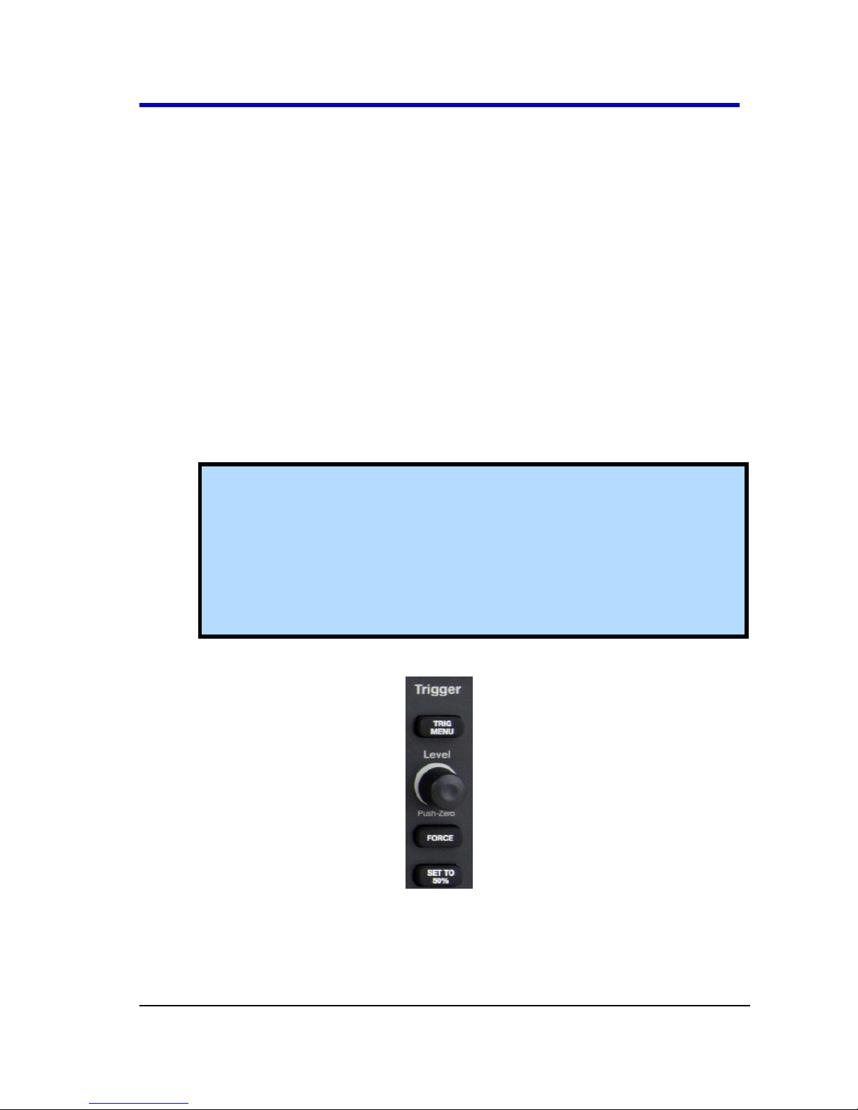
Trigger Controls
TRIG MENU - Press to display the Trigger menu. You can use the
Trigger menu to set the trigger type (Edge, Pulse, Video, Slope,
Alternative) and trigger settings.
Page 26

WaveAce 1000/2000
WA1K2K-OM-E RevB 19
SET TO 50% - Press to stabilize a waveform quickly. The
oscilloscope can set the Trigger Level to be halfway between the
minimum and maximum voltage levels automatically. This is useful
when you connect a signal to the EXT TRIG connector and set the
trigger source to Ext or Ext/5.
FORCE - Press to complete the current waveform acquisition
whether the oscilloscope detects a trigger or not. This is useful for
SINGLE acquisitions and Normal trigger mode.
LEVEL - Turn to select the trigger threshold level. Press the Level
front panel knob to set the trigger level to zero.
See Trigger Types (on page 39) for more information.
Page 27
Operator's Manual
20 WA1K2K-OM-E RevB
Probes
Probes
LeCroy provides a passive probe for each WaveAce oscilloscope channel.
Probe Compensation
Passive probes must be compensated to flatten overshoot. This is
accomplished by means of a trimmer on the probe body.
1. Attach the connector end of your probe to any channel.
2. Connect the probe end to the CAL output connector at the front of
the oscilloscope.
3. Adjust the trim pot on the probe body until the square wave is as
flat as possible.
4. Set the Probe option attenuation to 10X by pressing the Channel
button and then the Probe menu button.
5. Set the switch to 10X on the probe.
6. Attach the probe tip to the PROBE COMP~3V connector and the
reference lead to the PROBE COMP Ground connector. Press the
corresponding channel button, and then push the AUTO button.
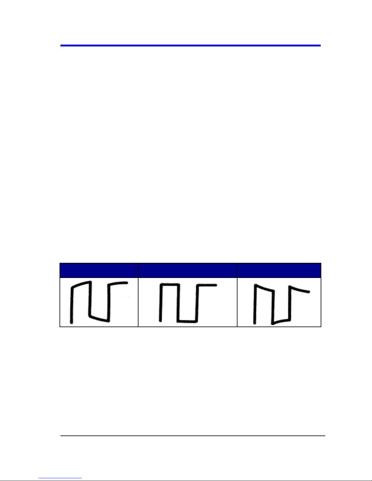
7. Check the shape of the displayed waveform as follows:
Overcompensated
Correctly Compensated
Undercompensated
See Setting Probe Attenuation (on page 30) in the Vertical Settings and
Channel Controls section for more information.
Page 28
WaveAce 1000/2000
WA1K2K-OM-E RevB 21
Viewing Waveforms
Turning On Traces
Turn on a channel trace by pressing the channel front panel button - CH1
or CH2 (or CH3 or 4 on 4 channel models). When you turn on a channel,
the Channel menu opens. You can then set up the vertical settings and
controls for the channel. When the channel is ON, the channel button is
lit.
Note: Turn a trace off by pressing the channel front panel button again.
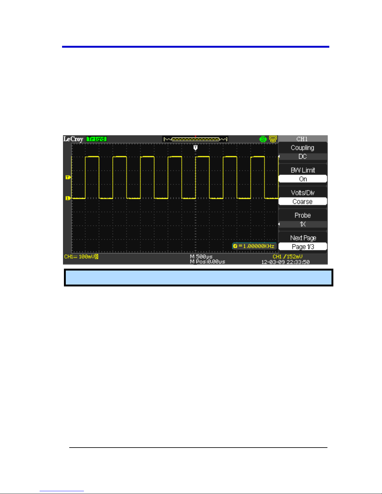
Setting Up the Display
You can access the Display menu pressing the DISPLAY front panel
button.
Page 29
Operator's Manual
22 WA1K2K-OM-E RevB
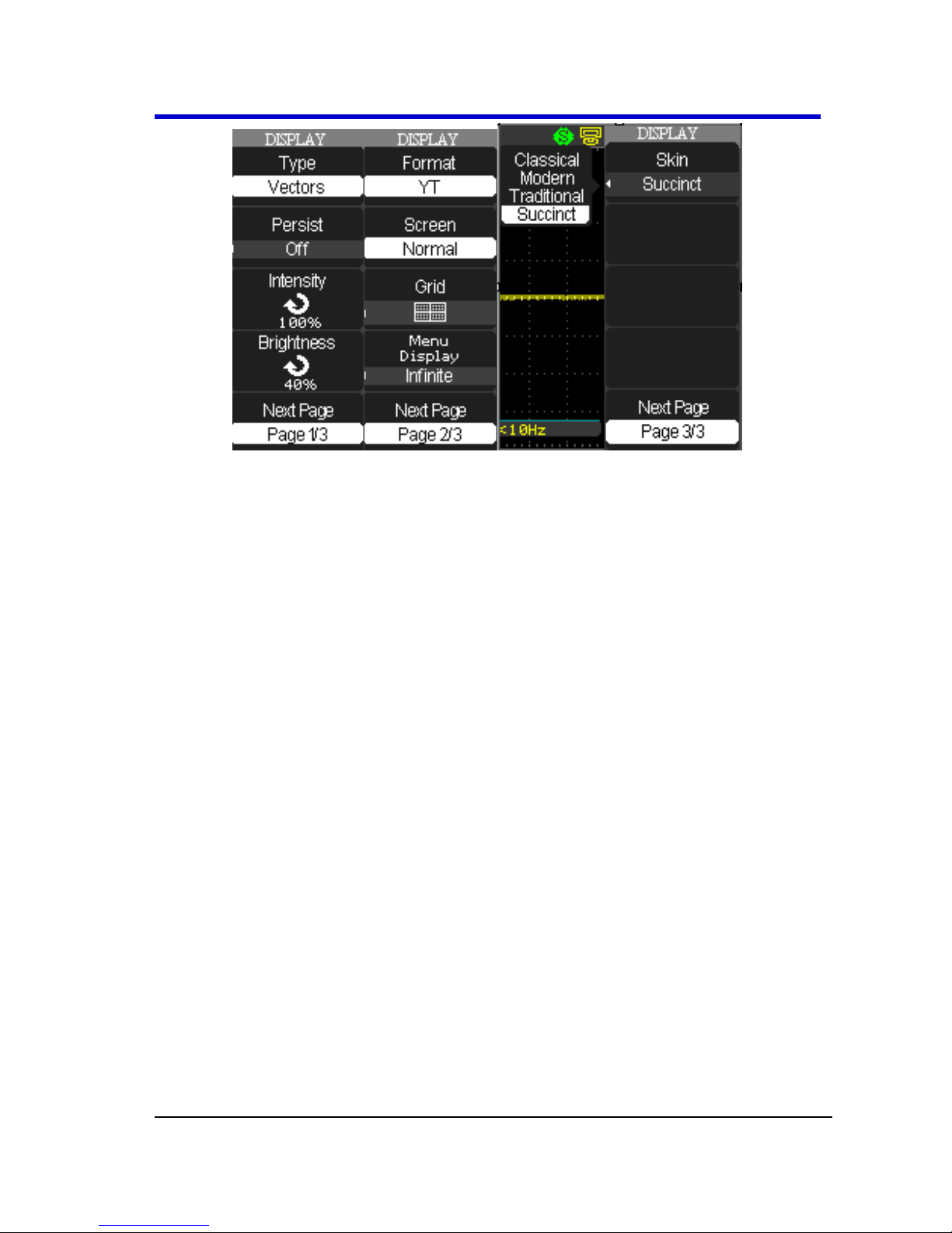
Display Menu Pages 1/3, 2/3, and 3/3 and their options are described as
follows:
1. Type - Vectors fill the space between adjacent sample points in
the display. Dots displays sample points directly.
2. Persist - Sets the length of time (1 sec, 2 sec, 5 sec, Infinite) each
displayed sample point remains displayed.
3. Intensity - Turn the Universal front panel knob to set the Intensity.
4. Brightness - Turn the Universal front panel knob to set the screen
brightness.
5. Format - Choose between YT format and XY format.
6. Screen - Set to Normal mode or Inverted color display mode.
7. Grid - Display grids and axes, turn off grids, or turn off grids and
axes.
8. Menu Display - Set the length of time the menus are shown on
screen (2 seconds, 5 seconds, 10 seconds, 20 seconds, or Infinite).
9. Skin - You can change the color of the software interface by
selecting Classical (default), Modern, Traditional, and Succinct
skin options.
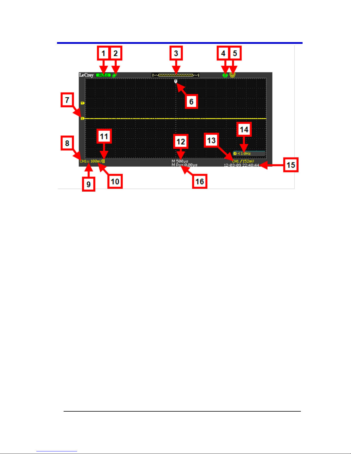
Understanding Display Information
The grid area contains several indicators to help you understand the
display. Indicators are coded to the channel colors).
Page 30
WaveAce 1000/2000
WA1K2K-OM-E RevB 23
The previously numbered indicators correspond with the following
explanations.
1. Trigger Status - The following four states are shown as highlighted
text on this part of the screen.
Armed - The oscilloscope is acquiring pre-trigger data. All
triggers are ignored in this state.
Ready - The oscilloscope is ready to trigger.
Trig'd - The oscilloscope has found a trigger and is acquiring
the post-trigger data.
Stop - The oscilloscope has stopped acquiring waveform
data. Shown in red highlight.
Acq. Complete - The oscilloscope has completed a Single
Sequence acquisition.
Auto - The oscilloscope is in Auto Mode and is acquiring
waveforms in the absence of triggers.
Scan - The oscilloscope is acquiring and displaying
waveform data continuously in Scan Mode.
2. USB Memory Device - Indicates whether the USB Memory Device
is inserted in the USB Port.
Page 31

Operator's Manual
24 WA1K2K-OM-E RevB
When a USB Memory Device is not inserted in the USB Port
the area is blank.
USB Memory Device is inserted in the USB Port (as
shown previous).
When plugging in or removing a USB Memory Device, a
message is briefly shown on the grid display as USB Flash
Drive Plug In! and USB Flash Drive Pull Out!, respectively.
3. Waveform Preview Display - This small portion at the top of the
screen shows how much of the captured waveform is currently
appearing on the display.
Note: Show the full waveform by stopping the trigger and turning the
Time/Div button to the left (increasing the amount of time shown on
the display).
4. Print Key - Indicates whether the Print Key option is set to Print
Picture or Save Picture.
Print Key option set to Save Picture (as shown previous).
Print Key option set to Print Picture
5. Back USB - Indicates whether the Back USB option is set to
Computer or Printer.
Back USB option set to Computer (as shown previous).
Back USB option set to Printer
6. Horizontal Trigger Position Marker - Shows the horizontal trigger
position.
7. Display Markers (Zero Volts Level) - Show the ground reference
points of the displayed waveforms. If there is no marker, the
channel is not displayed.
8. Display Signal Source
9. Signal Coupling symbol
10. Volts/Division
11. Indicates whether the bandwidth limiting filter is On or Off. The B
icon indicates the filter is On.
12. Main timebase setting (a Window timebase setting is also
displayed when applicable).
13. Trigger Source
Page 32

WaveAce 1000/2000
WA1K2K-OM-E RevB 25
14. Frequency Counter of Trigger Signal
15. Trigger type and level indicator
16. Horizontal Trigger Position Readout - Displays the waveform's
horizontal position in time (seconds).
Auto Setup
The Auto Setup function identifies the waveform type and automatically
adjusts controls to produce a usable input signal display.
Four Auto Setup waveform options are available: Multi-Cycle, Single-
Cycle, Rising Edge, and Falling Edge.
Press the AUTO front panel button, and then press the menu option
button adjacent to the desired waveform as follows:
Note: Use the bottom waveform menu button to Undo an applied Auto Setup.
Page 33

Operator's Manual
26 WA1K2K-OM-E RevB
Option
Description
(Multi-cycle)
Auto set the screen and display several cycle signal.
(Single-cycle)
Set the screen and auto display single cycle signal.
(Rising edge)
Auto set and show the rising time.
(Falling edge)
Auto set and show the falling time.
(Undo Setup)
Causes the oscilloscope to recall the previous setup.
Page 34
WaveAce 1000/2000
WA1K2K-OM-E RevB 27
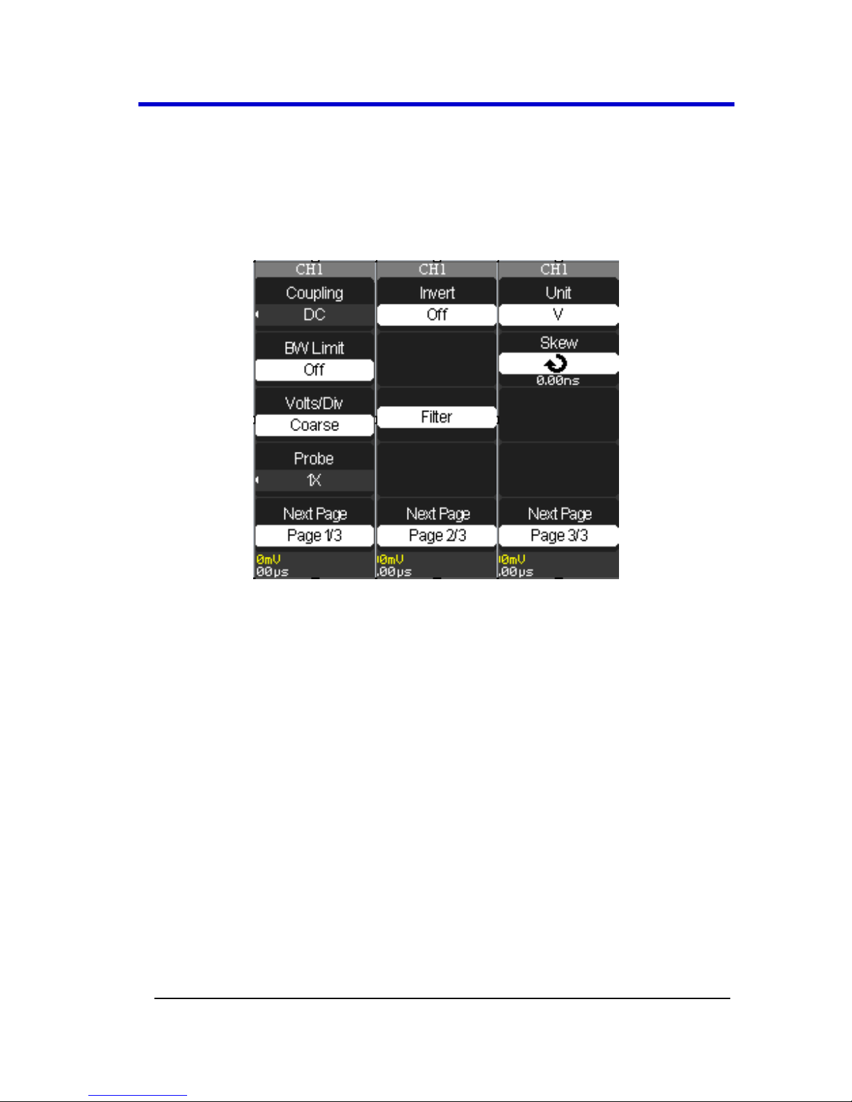
Vertical Settings and Channel Controls
Vertical Settings and Channel Controls
When you turn a channel trace ON, the Channel menu opens. The
Channel menu page shown (1/3, 2/3, or 3/3) is always based on the most
recent trace activated.
Choosing Coupling
You can choose one of these input coupling modes:
DC - Passes both AC and DC components of the input signal.
AC - Blocks the DC component of the input signal and attenuates
signals below 10 Hz.
GND - Disconnects the input signal. Use GND coupling to display a
zero-volt waveform. Internally, the channel input is connected to a
zero-volt reference level.
PLEASE NOTE THE FOLLOWING:
If the channel is set to DC coupling, you can quickly measure the
DC component of the signal by simply noting its distance from the
ground symbol.
If the channel is set to AC coupling, the DC component of the
signal is blocked allowing you to use greater sensitivity to display
the AC component of the symbol.
Page 35

Operator's Manual
28 WA1K2K-OM-E RevB
1. Choose an input coupling mode. Turn on the desired channel by
pressing the appropriate channel button - CH1 or CH2 (or CH3 or 4
on 4 channel models).
2. Now, press the Coupling option button on page 1/2 of the channel
menu, and then select a coupling mode from the menu.
3.
Limiting Bandwidth
You can limit the bandwidth to reduce display noise. When you turn
Bandwidth Limit ON, the Bandwidth Limit value is set to 20 MHz. It also
filters the signal to reduce noise and other unwanted high frequency
components.
Note: The oscilloscope vertical response rolls off slowly above its bandwidth;
or, above 20 MHz when the Bandwidth Limit is set to ON. Therefore, the FFT
spectrum can show valid frequency information higher than the oscilloscope
bandwidth. However, the magnitude information near or above the bandwidth
will not be accurate.
1. Turn the Bandwidth Limit ON by activating the specific channel.
Press the desired channel button - CH1 or CH2 (or CH3 or 4 on 4
channel models).
Page 36

WaveAce 1000/2000
WA1K2K-OM-E RevB 29
2. Now, press the BW Limit option button on page 1/2 of the channel
menu, and then select On.
Note: A highlighted B icon is shown at the lower-left of the display as
described in Understanding Display Information (on page 24).
Adjusting Sensitivity
You can set the sensitivity of the Volts/Div using the front panel knob.
When the sensitivity is Coarse (or fixed - the default setting), the gain
adjustment is set to 1-2-5 increments from 2 mV/div, 5 mV/div, 10
mV/div to 5 V/div. Pushing the Volts/Div knob sets the sensitivity to Fine
(variable), and changes the resolution to small steps between the coarse
settings.
Note: The vertical scale readout displays the actual Volts/Div setting when
Fine(variable) is selected. Changing the setting to Coarse (fixed) does not
change the vertical scale until the Volts/Div control is adjusted.
1. Set the sensitivity of the Volts/Div front panel knob by turning on
the specific channel. Press the desired channel button - CH1 or
CH2 (or CH3 or 4 on 4 channel models).
Page 37

Operator's Manual
30 WA1K2K-OM-E RevB
2. Now, press the Volts/Div option button on page 1/3 of the
channel menu, and then select Coarse (fixed) or Fine (variable).
Setting Probe Attenuation
Probes are available with various attenuation factors affecting the
vertical scale of the signal. Push the Channel button, and then the Probe
menu option button. Attenuation options for 1X, 10X, 50X, 100X, 500X,
and 1000X.
PLEASE NOTE THE FOLLOWING:
The default setting for the Probe option is 1X.
Be sure that the Attenuation switch on the probe matches the
Probe option in the oscilloscope. Switch settings are 1X and 10X.
Page 38

WaveAce 1000/2000
WA1K2K-OM-E RevB 31
When the Attenuation switch is set to 1X, the probe limits the
bandwidth of the oscilloscope to 10MHz. To use the full
bandwidth of the oscilloscope, be sure to set the switch to 10X.
Inverting Waveforms
Use the following steps to invert your waveform.
1. Invert the waveform by turning on the specific channel. Press the
desired channel button - CH1 or CH2 (or CH3 or 4 on 4 channel
models).
2. Now, on the channel menu, press the Next Page option button,
showing page 2/3.
3. Press the Invert option button on page 2/3, and then select On.
Setting the Digital Filter
You can choose from the following digital filter types:
Low Pass Filter (LPF)
High Pass Filter (HPF)
Band Pass Filter (BPF)
Band Stop Filter
Use the following steps to set the digital filter.
1. Turn on the digital filter by pressing the desired channel button -
CH1 or CH2 (or CH3 or 4 on 4 channel models).
2. On the channel menu, press the Next Page option button, showing
page 2/3.
Page 39

Operator's Manual
32 WA1K2K-OM-E RevB
3. Press the Filter option button on page 2/3. The Filter menu opens.
4. Press the Filter option button and select On.
5. Press the Type option button and select a digital filter type.
6. Press the Upp. Limit option button and turn the Adjust front panel
knob to set the Upper limit.
7. Press the Low. Limit option button and turn the Adjust front panel
knob to set the Lower limit.
Note: If you select the Low Pass Filter (LPF) type, you can only set an Upper
Limit. If you select the High Pass Filter (HPF) type, you can only set a Lower
Limit. For both Band Pass Filter (BPF) and Band Stop Filter, you can set both
Upper and Lower Limits.
Unit and Skew Settings
On the channel menu, press the Next Page option button, showing page
3/3. This menu allows you to set your desired Unit and Skew values.
Page 40

WaveAce 1000/2000
WA1K2K-OM-E RevB 33
1. Pressing the Unit option button selects between V (Volts) and A
(Amperes) values.
2. Pressing the Skew option button enables the Adjust front panel
knob to set your desired value.
Page 41

Operator's Manual
34 WA1K2K-OM-E RevB
Acquisition Types
Acquisition Types
When you acquire a signal, the oscilloscope converts it into a digital form
and displays a waveform. The acquisition sampling mode defines how the
signal is digitized and the timebase setting affects the time span and level
of detail in the acquisition. You can change the Sampling modes by
pressing the ACQUIRE front panel button.
There are three basic acquisition types:
Sampling- samples the signal in evenly-spaced intervals to
construct the waveform.
Note: You can use this type to reduce random noise. This type does
not acquire rapid variation in the signal that may occur between
samples. This can result in narrow pulses being missed. In this case, use
Peak Detect to acquire data.
Peak Detect - captures the maximum and minimum values that
occur in a signal. It finds the highest and lowest record points over
many acquisitions.
Note: The oscilloscope can acquire and display narrow pulses, which
may otherwise have been missed in Sampling mode. Noise appears
higher in this mode.
Average - acquires up to 256 waveforms, averages them, and
displays the resulting waveform.
Note: This type can be used to reduce random noise.
Use the following steps to choose a sampling type.
1. Press the ACQUIRE front panel button. On the Acquire menu,
press the Acquisition option button and select a sampling type.
Page 42

WaveAce 1000/2000
WA1K2K-OM-E RevB 35
2. If you select the Average sampling type, press the Averages option
button and select the number of waveforms (4, 16, 32, 64, 128, or
256).
Sinx/x
Choose Sinx or x by pressing the corresponding option button. This turns
Sinx/x on or off, respectively.
Sinx/x interpolation is suitable for reconstructing curved or irregular
wave shapes, especially when the sample rate is 3 to 5 times the system
bandwidth.
Mode Selection
You can choose between Equivalent Time Sampling and Real Time
Sampling settings.
Page 43

Operator's Manual
36 WA1K2K-OM-E RevB
Equivalent Time Sampling can achieve up to 20 ps of horizontal
resolution (equivalent to 50 GS/s). This mode is good for observing
repetitive waveforms.
Real Time Sampling can be used for repetitive and non-repetitive
waveforms.
Select from the sampling settings by pressing the Mode option button
and selecting Real Time or Equ Time.
Sampling Rate
Adjust the sampling rate by pressing the Sa Rate option button and
turning the Time/div front panel knob. The sampling rate is shown at the
corresponding timebase scale.
Page 44

WaveAce 1000/2000
WA1K2K-OM-E RevB 37
Acquiring Waveforms
You can choose to acquire a single waveform or to acquire waveforms
continuously. If you want to acquire a single waveform, press the SINGLE
front panel button. Each time you press the SINGLE front panel button,
the oscilloscope begins to acquire another waveform. After the
oscilloscope detects a trigger, it completes the acquisition and stops. If
you want to acquire waveforms continuously, press the RUN/STOP front
panel button. Press the button again to stop the acquisition.
When you start an acquisition, the oscilloscope goes through the
following steps:
1. Acquires enough data to fill the portion of the waveform record to
the left of the trigger point (pre-trigger).
2. Continues to acquire data while waiting for the trigger condition
to occur.
3. Detects the trigger condition.
4. Continues to acquire data until the waveform record is full.
5. Displays the waveform.
Changing the Timebase
The oscilloscope digitizes waveforms by acquiring the value of an input
signal at discrete points. The timebase allows you to control how often
the values are digitized. You can change the timebase using the Time/div
front panel knob in the Horizontal Control group.
Note: As you turn the Time/div front panel knob, the value is displayed at the
lower-center of the display as described in Understanding Display
Information (on page 22).
Zooming Waveforms
The Delayed option button on the Horizontal menu (or pressing the
Time/Div Front Panel (on page 10) knob) toggles between a state where
the display provides a split-screen layout where an upper trace shows the
actual waveform with a shaded, mask-like portion covering the nonzoomed portion of the waveform; the lower trace displays the actual
zoom segment. While in this view, turn the Push Zoom Front Panel (on
page 10) knob to adjust the zoom portion of the trace.
Page 45

Operator's Manual
38 WA1K2K-OM-E RevB
1. Press the HORI MENU front panel button. The Horizon menu is
shown.
2. Press the Delayed option button on the Horizontal menu (or
pressing the Time/Div Front Panel (on page 10) knob).
3. Turn the Time/Div front panel knob to adjust the Zoom segment
window size.
Note: Select a Delayed ON/OFF value or press the Time/Div Front
Panel knob to toggle between a state where the display provides a
split-screen layout where an upper trace shows the actual waveform
with a shaded, mask-like portion covering the non-zoomed portion of
the waveform; the lower trace displays the actual zoom segment. With
the Delay value ON or OFF, turning the Time/Div Front Panel knob
adjusts the Zoom function.
4. Turn the Horizontal Position Front Panel (on page 10) knob to
adjust the window's position.
5. Press the MemDepth option button to select from Normal and
LongMem values.
Page 46

WaveAce 1000/2000
WA1K2K-OM-E RevB 39
Triggering
Trigger Types
There are five trigger types: Edge, Video, Pulse, Slope, and Alternative.
Access the trigger modes by pressing the TRIG MENU front panel button
(in the Trigger control group) and selecting Type from the Trigger menu.
Edge Triggering
1. Press the Type menu option button and select Edge.
2. Press the Source option button to choose a channel input (CHS 1 -
2; or CHS 1 - 4 on 4 channel models) or EXT, EXT/5, AC Line input.
3. Use Slope to select a positive or negative edge for Edge Triggering
(rising edge, falling edge, or both).
4. Press the Mode option button to select Auto, Normal, or Single
mode. Use Auto mode to let the acquisition automatically run in
the absence of a trigger. Use Normal mode when you want to see
only valid triggered waveforms (when you use this mode the
oscilloscope does not display a waveform until after the first
trigger). Use Single mode when you want the oscilloscope to
acquire a single waveform.
5. Press the Setup... option button to display the Trigger Setup...
menu. You can use the Trigger Setup... menu to select a coupling
mode and define a Holdoff value. Coupling modes comprise DC,
AC, HF Reject, and LF Reject. Turn the Adjust front panel knob to
set the Holdoff value.
Page 47

Operator's Manual
40 WA1K2K-OM-E RevB
Pulse Triggering
Use Pulse width triggering to trigger on aberrant pulses. You can select
how to compare the trigger pulse relative to the pulse width as follows:
Positive pulse width less than pulse width setting
Positive pulse width larger than pulse width setting
Positive pulse width equal to pulse width setting
Negative pulse width less than pulse width setting
Negative pulse width larger than pulse width setting
Negative pulse width equal to pulse width setting
1. Press the Type option button and select Pulse.
2. Press the Source option button to choose a channel input (CHS 1 -
2; or CHS 1 - 4 on 4 channel models) or EXT, EXT/5, AC Line input.
3. Press the When option button to select how to compare the
trigger pulse relative to the value selected in the Set Width option.
4. Press the Set Width option button and then turn the Adjust front
panel knob to set the pulse width.
5. Press the Next Page option button.
6. Press the Mode option button to select Auto, Normal, or Single
mode. Use Auto mode to let the acquisition automatically run in
the absence of a trigger. Use Normal mode when you want to see
only valid triggered waveforms (when you use this mode the
oscilloscope does not display a waveform until after the first
Page 48

WaveAce 1000/2000
WA1K2K-OM-E RevB 41
trigger). Use Single mode when you want the oscilloscope to
acquire a single waveform.
7. Press the Setup... option button to display the Trigger Setup...
menu. You can use the Trigger Setup... menu to select a coupling
mode and define a Holdoff value. Coupling modes comprise DC,
AC, HF Reject, and LF Reject. Turn the Adjust front panel knob to
set the Holdoff value.
Video Triggering
Use Video Triggering to trigger on fields or lines of standard video signals.
1. Press the Type option button and select Video.
2. Press the Source option button to choose a channel input (CHS 1 -
2; or CHS 1 - 4 on 4 channel models) or EXT, EXT/5, AC Line input.
3. Press the Polarity option button and select (Normal)
or ( Inverted). Normal triggers on the negative edge of the
sync pulse. Inverted triggers on the positive edge of the sync
pulse.
4. Press the Sync option button and select a video sync (Line Num,
All Lines, Odd Field, Even Field). If you select Line Num, you can
turn the Adjust front panel knob to set the appointed line number.
5. Press the Next Page option button.
6. Press the Standard option button and select the video standard
for sync and line number count (NTSC or Pal/Secam).
7. Press the Mode option button to select Auto, Normal, or Single
mode. Use Auto mode to let the acquisition automatically run in
Page 49

Operator's Manual
42 WA1K2K-OM-E RevB
the absence of a trigger. Use Normal mode when you want to see
only valid triggered waveforms (when you use this mode the
oscilloscope does not display a waveform until after the first
trigger). Use Single mode when you want the oscilloscope to
acquire a single waveform.
8. Press the Setup... option button to display the Trigger Setup...
menu. You can use the Trigger Setup... menu to select a coupling
mode and define a Holdoff value. Coupling modes comprise DC,
AC, HF Reject, and LF Reject. Turn the Adjust front panel knob to
set the Holdoff value.
Slope Triggering
Use Slope Triggering to trigger on the positive slope or negative slope
depending on the trigger conditions and time you set.
1. Press the Type option button and select Slope.
2. Press the Source option button to choose a channel input (CHS 1 -
2; or CHS 1 - 4 on 4 channel models) or EXT, EXT/5, AC Line input.
3. Press the When option button to select the trigger condition.
4. Press the Time option button and then turn the Adjust front panel
knob to set the slope time.
5. Press the Next Page option button.
6. Press the Vertical option button and select the trigger level that
can be adjusted using the Level front panel knob. You can adjust
Level A, Level B, or adjust both at the same time.
Page 50

WaveAce 1000/2000
WA1K2K-OM-E RevB 43
7. Press the Mode option button to select Auto, Normal, or Single
mode. Use Auto mode to let the acquisition automatically run in
the absence of a trigger. Use Normal mode when you want to see
only valid triggered waveforms (when you use this mode the
oscilloscope does not display a waveform until after the first
trigger). Use Single mode when you want the oscilloscope to
acquire a single waveform.
8. Press the Setup... option button to display the Trigger Setup...
menu. You can use the Trigger Setup... menu to select a coupling
mode and define a Holdoff value. Coupling modes comprise DC,
AC, HF Reject, and LF Reject. Turn the Adjust front panel knob to
set the Holdoff value.
Alternative Triggering
The trigger signal comes from two vertical channels when you use
Alternative Triggering. Using this type of trigger, you can observe two
unrelated signals at the same time. For each signal, you can select
different trigger types, such as Edge, Pulse, Slope, or Video. Trigger
information for the two channels is displayed at the bottom right side of
the display.
1. Press the Type option button and select Alternative.
2. Set up both triggers by pressing the Source option button and
selecting a Source - CH1 or CH2 (or CH3 or 4 on 4 channel models).
3. For the selected Source, press the Mode option button and select
a Trigger Type (Edge, Pulse, Slope, or Video).
Page 51

Operator's Manual
44 WA1K2K-OM-E RevB
4. For the selected trigger type, set the trigger options.
5. Press the Setup... option button to display the Trigger Setup...
menu. You can use the Trigger Setup... menu to select a coupling
mode and define a Holdoff value. Coupling modes comprise DC,
AC, HF Reject, and LF Reject. Turn the Adjust front panel knob to
set the Holdoff value.
Page 52

WaveAce 1000/2000
WA1K2K-OM-E RevB 45
Analyzing Waveforms
Analyzing Waveforms
Four main front panel buttons are used for waveform analysis.
Two Menu Function front panel buttons - Cursors, Measure
The other two are Vertical front panel buttons - Math, REF
The following topics explain their detailed use.
Measuring with Cursors
Cursors are important tools that aid you in measuring signal values.
Cursors are boundary markers you can move across the grid. Use cursors
to make fast, accurate measurements and eliminate guesswork.
There are three cursor measurement modes:
1. Manual - displays two horizontal parallel cursors or vertical
parallel cursors to measure voltage or time, respectively.
Page 53

Operator's Manual
46 WA1K2K-OM-E RevB
Voltage cursors appear as horizontal lines on the display and
measure the vertical parameters. Time cursors appear as vertical
lines on the display and measure the horizontal parameters.
Move cursors by pressing corresponding CurA, CurB option
buttons, and then using the Adjust front panel knob. Before using
cursors, you should make sure that you have set the signal source
as the channel for measuring.
2. Track - displays two cross-cursors. The cross-cursors set the
position on the waveform automatically.
Page 54

WaveAce 1000/2000
WA1K2K-OM-E RevB 47
You can adjust the cursor position on the waveform by turning the
Adjust front panel knob. Measurement values are shown in the
upper-left corner of the grid display.
3. Auto - Automatically places markers of what is being measured on
the waveform. These markers clarify parameter measurements by
displaying cursors and a visual representation of what is being
measured. When in Auto cursor mode, as you select measurement
parameters the markers will be displayed for the measurements.
Cursor Measurement Selections
Time cursors are vertical lines that you move horizontally to
measure the difference in time or frequency values between the
cursors.
Voltage cursors appear as horizontal lines on the display and
measure the vertical parameters.
Measurement values are shown in the upper-left corner of the
grid display and are explained as follows:
Shown in Manual Cursor Mode
▲V - the vertical space between Cursor A and Cursor B (Voltage
value between the two cursors)
CurB - the horizontal position of Cursor B (in Volts)
CurA - the horizontal position of Cursor A (in Volts)
Shown in Track Cursor Mode
Page 55

Operator's Manual
48 WA1K2K-OM-E RevB
A→T - the horizontal position of Cursor A (Time cursor centered
around the midpoint of the screen)
A→V - the vertical position of Cursor A (Voltage cursor centered
on the channel ground level)
B→T - the horizontal position of Cursor B (Time cursor centered on
the midpoint of the screen)
B→V - the vertical position of Cursor B (Voltage cursor centered
around the channel ground level)
▲T - Horizontal space between Cursor A and Cursor B (Time value
between the two cursors)
1/▲T - the reciprocal of the horizontal space between Cursor A and
Cursor B
▲V - the vertical space between Cursor A and Cursor B (Voltage
value between the two cursors)
Cursor Placement
1. Press the CURSORS front panel button. The Cursor menu opens.
2. Now, cursor placement depends on the cursor measurement
Mode selected - Manual, Track, or Auto - in the following manner:
Manual
Set the mode to Manual by pressing the Mode option button until
Manual is selected. Press the Type option button and select
Page 56

WaveAce 1000/2000
WA1K2K-OM-E RevB 49
Voltage (horizontal cursors) or Time (vertical cursors). Press the
Source option button and select a source of CH1, CH2 (also, CH3
and 4 on 4 channel models). Manual Mode also allows you to
choose MATH, REFA, or REFB as a Cursor source. Press the CurA or
CurB option button and turn the Adjust front panel knob to adjust
the cursors.
OR
Track
Set the mode to Track by pressing the Mode option button until
Track is selected. Press the Cursor A or Cursor B option button and
select a source of CH1, CH2 (also, CH3 and 4 on 4 channel models)
or NONE. Press the CurA or CurB option button and turn the
Adjust front panel knob to adjust the cursors. If Track is selected,
both cursors move in unison and appear slightly brighter on the
grid display.
OR
Auto
Set the mode to Auto by pressing the Mode option button until
Auto is selected. When you select measurement parameters using
the MEASURE front panel button, the cursors are automatically
displayed.
Note: When using Cursors, their measurement values are always shown in the
upper-left corner of the grid display. The cursor selected for placement is
indicated by a highlighted icon on the menu and the cursor itself has a higher
brightness on the grid display.
Parameter Measurements
Waveform analysis typically begins with the measurement of
parameters. Parameter measurement tools determine a wide range of
waveform properties. Use them to automatically calculate many of your
waveform attributes, like rise time, rms voltage, and peak-to-peak
voltage, for example.
Access parameter measurements by pressing the MEASURE front panel
button. The main Measure menu is shown. Notice how each row on the
Page 57

Operator's Manual
50 WA1K2K-OM-E RevB
Measure menu is labeled with a CHX, a Type, and a Value. Each row is a
customizable parameter measurement preset.
Press the corresponding option button to show additional preset controls
for Voltage, Time, Delay, and AllMea for the Source channel selected.
Page 58

WaveAce 1000/2000
WA1K2K-OM-E RevB 51
Voltage Measurement Parameters
First select a Source Channel for your Voltage measurement parameter
by pressing the Source option button. Now, use the Type option button
to choose from the following Voltage measurement parameters for your
selected source.
Vpp - Difference between highest and lowest points in the
waveform.
Vmax - Measures highest point in waveform. Unlike top, it
does not assume the waveform has two levels.
Vmin - Measures the lowest point in a waveform. Unlike
base, it does not assume the waveform has two levels.
Mean - Average of the data for a time domain waveform.
Computed as centroid of distribution for a histogram.
Vrms - Root Mean Square of data between the cursors -
about the same as sdev for a zero-mean waveform.
Crms - Cyclic root mean square: Computes the square root
of the sum of squares of data values divided by number of points.
Contrary to rms, calculation is performed over an integer number
of cycles, eliminating bias caused by fractional intervals.
Vtop - Higher of two most probable states, the lower being
base; it is characteristic of rectangular waveforms and represents
the higher most probable state determined from the statistical
distribution of data point values in the waveform.
Page 59

Operator's Manual
52 WA1K2K-OM-E RevB
Vbase - Lower of two most probable states (higher is top).
Measures lower level in two-level signals. Differs from min in that
noise, overshoot, undershoot, and ringing do not affect
measurement.
Vavg - Arithmetic mean over the first cycle in the
waveform.
Vamp - Voltage between Vtop and Vbase of a waveform.
ROVShoot - (Vmax-Vtop)/Vamp after the waveform rising
transition.
FOVShoot - (Vmin-Vbase)/Vamp after the waveform falling
transition.
RPREShoot - (Vmin-Vbase)/Vamp before the waveform
rising transition.
FPREShoot - (Vmax-Vtop)/Vamp before the waveform
falling transition.
Time Measurement Parameters
First select a Source Channel for your Time measurement parameter by
pressing the Source option button. Now, use the Type option button to
choose from the following Time measurement parameters for your
selected source.
Period - Period of a cyclic signal measured as time between
every other pair of 50% crossings. Starting with first transition
Page 60

WaveAce 1000/2000
WA1K2K-OM-E RevB 53
after left cursor, period is measured for each transition pair, with
values averaged to give final result.
+Wid - Time between the first rising edge and the next
rising edge at the waveform 50% level.
-Wid - Time between the first falling edge and the next
rising edge at the waveform 50% level.
Rise Time - Duration of pulse waveform's rising transition
from 10% to 90%, averaged for all rising transitions between the
cursors.
Fall Time - Duration of pulse waveform's falling transition
from 90% to 10%, averaged for all falling transitions between the
cursors.
BWid - Duration of a burst measured over the entire
waveform.
+Dut - Ratio between positive pulse width and period.
-Dut - Ratio between negative pulse width and period.
Delay Measurement Parameters
First select a Source Channel for your Delay measurement parameter by
pressing the Source option button. Now, use the Type option button to
choose from the following Delay measurement parameters for your
selected source.
Page 61

Operator's Manual
54 WA1K2K-OM-E RevB
Phase - Amount one waveform leads or lags another in
time expressed in degrees, where 360 degrees comprise one
waveform cycle.
FRR - Time between the first rising edge of Source 1 and
the first rising edge of Source 2.
FRF - Time between the first rising edge of Source 1 and
the first falling edge of Source 2.
FFR - Time between the first falling edge of Source 1 and
the first rising edge of Source 2.
FFF - Time between the first falling edge of Source 1 and
the first falling edge of Source 2.
LRR - Time between the first rising edge of Source 1 and
the last rising edge of Source 2.
LRF - Time between the first rising edge of Source 1 and
the last falling edge of Source 2.
LFR - Time between the first falling edge of Source 1 and
the last rising edge of Source 2.
LFF - Time between the first falling edge of Source 1 and
the last falling edge of Source 2.
All Mea (Measurement) Settings
Pressing the All Mea option button shows a menu where you can choose
to display a given set of measurement values for a Source Channel, and
turn On or Off its corresponding measurement values for Voltage and
Time on the grid display.
Page 62

WaveAce 1000/2000
WA1K2K-OM-E RevB 55
Press corresponding option buttons and make selections as desired.
Waveform Math
Standard math functions include addition, subtraction, multiplication,
division, and FFT. For more information on FFT, see the FFT Spectrum
Analyzer (on page 57) section. Press the MATH front panel button in the
Vertical Control group to display the Math menu.
Math on 2 Channel WaveAce Models
1. Press the Operation option button and select a math operator +, -,
*, /, or FFT Spectrum Analyzer (on page 57).
Page 63

Operator's Manual
56 WA1K2K-OM-E RevB
2. The Source can be any channel, but not another math trace.
Channel behavior for the math operators allow for CH1-CH2 or
CH2-CH1 selections.
Math on 4 Channel WaveAce Models
Math Menu Pages 1/2 and 2/2 and their options are described as follows:
1. Press the Operation option button and select a math operator A +
B,A - B, A * B, /, or FFT Spectrum Analyzer (on page 57).
2. The Source can be any channel, but not another math trace.
Channel behavior for the math operators force CH1+CH2 or
CH3+CH4 selection pairings (using addition as an example).
Note: Invert a waveform by pressing the CH1Invert or CH2Invert (or
CH3Invert or CH4Invert on 4 Channel models) option button and select On.
3. Position your math trace vertically by pressing the following
option button and turning the Adjust knob as desired.
Page 64

WaveAce 1000/2000
WA1K2K-OM-E RevB 57
4. Adjust the scale of your math trace by pressing the following
option button and turning the Adjust knob as desired.
FFT Spectrum Analyzer
The FFT process mathematically converts a time-domain signal into its
frequency components. You can display only one FFT waveform at a
time. With the FFT Operation selected, the following menu options are
shown.
1. Press the Window option button and select from the following
choices.
Page 65

Operator's Manual
58 WA1K2K-OM-E RevB
Window
Type
Description
Test Content
Rectangular
Best frequency resolution,
worst magnitude
resolution. This is
essentially the same as no
window.
Symmetric transients or
bursts. Equal-amplitude sine
waves with fixed frequencies.
Broadband random noise with
a relatively slowly varying
spectrum.
Hanning
Better frequency, worse
magnitude accuracy than
Rectangular.
Sine, periodic, and narrowband random noise.
Asymmetric transients or
bursts.
Hamming
Better frequency, worse
magnitude accuracy than
Rectangular. Hamming has
slightly better frequency
resolution than Hanning.
Sine, periodic, and narrowband random noise.
Asymmetric transients or
bursts.
Blackman
Best magnitude, worst
frequency resolution.
Single frequency waveforms to
find higher order harmonics.
2. Press the FFT Zoom option button and select from 1X, 2X, 5X, and
10X choices.
3. Use the Scale option button to choose either dBVrms or Vrms
appropriately for your FFT trace.
Page 66

WaveAce 1000/2000
WA1K2K-OM-E RevB 59
Note: The previous screen-shot shows a math trace in Split Display
view.
4. The Display option button allows you to choose either Split or Full
Screen for your FFT trace display.
Note: The previous screen-shot shows a math trace in Full Screen
Display view.
Creating Reference Waveforms
Two reference waveforms (REFA and REFB) can be created and saved
into internal memory on the oscilloscope.
Reference waveforms can be saved and recalled from volatile memory
for quick comparative analysis.
PLEASE NOTE THE FOLLOWING:
When reference waveforms are recalled from internal memory,
their horizontal position and scale cannot be adjusted.
However, the oscilloscope does display the horizontal and vertical
scales of the recalled reference waveforms at the bottom of the
display.
X-Y mode waveforms are not stored as reference waveforms.
Creating Reference Waveforms
1. Press the REF front panel button. The REF WAV menu opens.
Page 67

Operator's Manual
60 WA1K2K-OM-E RevB
2. Press the Source option button to select the input signal channel.
3. Use the lower REF A option button to turn the reference
waveform On or Off.
This also shows or hides the reference waveform from the grid
display area. Now, you can make adjustments to your waveform
leaving the REF A trace intact for comparison. There's also a
reference waveform indicator shown on the upper-right of the
grid display.
4. Press the middle REF A option button to switch from REF A to
REF B. Both the middle and lower REF A option buttons now show
labeled as REF B and adjustments can be made for the additional
reference waveform.
Page 68

WaveAce 1000/2000
WA1K2K-OM-E RevB 61
5. Use the Save option button to save your reference waveform for
comparative analysis at a later time.
Note: Keep in mind that the reference waveforms are stored in volatile
memory. This means that REF A and REF B are temporarily stored until
the next time the oscilloscope is shut down.
Page 69

Operator's Manual
62 WA1K2K-OM-E RevB
Save and Recall
Saving and Recalling Oscilloscope Settings
You can quickly save and recall up to 20 oscilloscope panel settings and
20 waveforms in internal memory. Waveforms and panel settings can
also be saved to a USB memory device.
Saving the Current Settings
1. Press the Save/Recall front panel button. The SAVE/REC menu is
shown.
2. Press the Type option button and select Setups.
3. Save your setup either to Device (meaning internal memory on
your WaveAce) or File (for storage on a USB memory device)
using the following methods.
Saving Setups to Internal Memory
Press the Save To option button to select Device.
Press the Setup... option button or turn the Adjust front
panel knob and assign a number (No. 1 - No. 20) to the
setup.
Press the Save option button to save the current setup.
The setup is saved to memory and the oscilloscope briefly
shows a Store Data Success! message on the lower part of
the grid display area.
Saving Setups to a USB Memory Device
Page 70

WaveAce 1000/2000
WA1K2K-OM-E RevB 63
Insert the USB memory device, press the Save To option
button and select File.
Press the Save option button and the SAVE ALL screen
opens showing Directorys by default. Finish saving your
setup using the following instructions in Using the SAVE ALL
Screen (on page 74).
1. Switch to the SAVE ALL - Files Menu - covered in the
Using the SAVE ALL Screen (on page 74) topic.
2. Name and Confirm your file using the steps explained
in Creating Folders and Files - also covered in the
Using the SAVE ALL Screen (on page 74) topic.
Recalling Setups
1. If you're not already on the SAVE/REC menu, press the
Save/Recall front panel button and the SAVE/REC menu is shown.
2. Press the Type option button and select Setups.
3. Recall your setup either from your Device (meaning internal
memory on your WaveAce) or from a File (stored on a USB
memory device) using the following methods.
Recalling Setups from Internal Memory
Press the Save To option button to select Device.
Press the Setup... option button or turn the Adjust front
panel knob to select the number (No. 1 - No. 20) assigned
to the setup you want to recall.
Press the Recall option button and the selected Setup is
recalled from internal memory. The oscilloscope briefly
Page 71

Operator's Manual
64 WA1K2K-OM-E RevB
shows a Read Data Success! message on the lower part of
the grid display area.
Recalling Setups from a USB Memory Device
Insert the USB memory device and press the Save To option
button to select File.
Press the Recall option button and the SAVE ALL screen is
shown. See Using the SAVE ALL Screen (on page 76) to
continue recalling from your USB memory device.
Saving and Recalling Waveforms
You can quickly save waveforms in internal memory (up to 20
waveforms) or on a USB memory device (limited only by your USB
memory device capacity). You can display up to three waveforms at the
same time. You can easily recall these saved waveforms later.
Saving Waveforms
1. Display the waveform(s) you want to save and press the
Save/Recall front panel button. The SAVE/REC menu is shown.
2. Press the Type option button and select Waveforms.
3. Save the waveform either to Device (meaning internal memory on
your WaveAce) or File (for storage on a USB memory device) using
the following methods.
Saving Waveforms to Internal Memory
Press the Save To option button to select Device.
Page 72
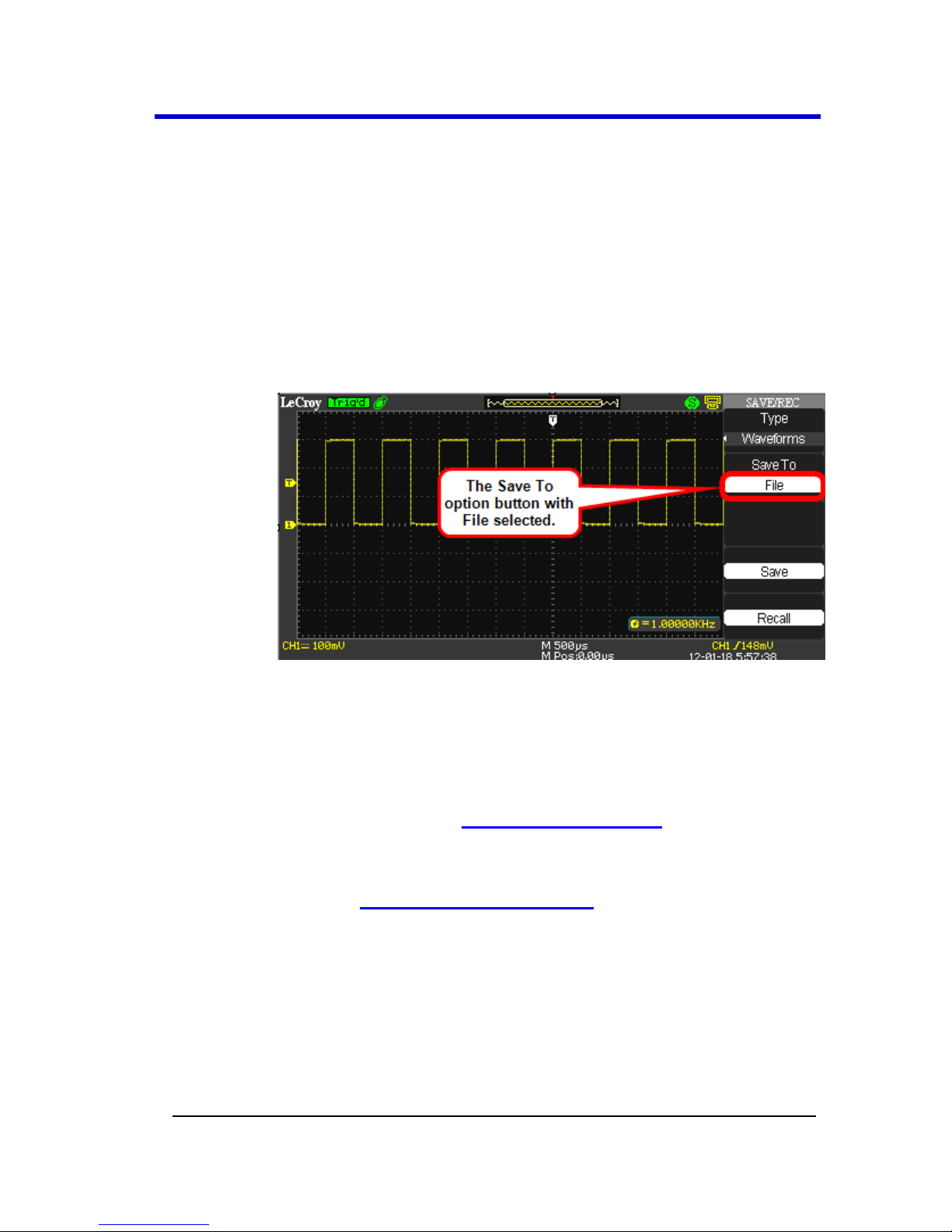
WaveAce 1000/2000
WA1K2K-OM-E RevB 65
Press the Waveform option button or turn the Adjust knob
to assign a number (No. 1 - No. 20) to the waveform.
Press the Save option button to save the waveform.
The waveform is saved to memory and the oscilloscope
briefly shows a Store Data Success! message on the lower
part of the grid display area.
Saving Waveforms to a USB Memory Device
Insert the USB memory device, press the Save To option
button, and select File.
Press the Save option button to save the waveform.
Now, the SAVE ALL screen opens showing Directorys by
default. Finish saving to your USB memory device using the
following instructions in Using the SAVE ALL Screen (on
page 74).
1. Switch to the SAVE ALL - Files Menu - covered in the
Using the SAVE ALL Screen (on page 74) topic.
2. Name and Confirm your file using the steps explained
in Creating Folders and Files - also covered in the
Using the SAVE ALL Screen (on page 74) topic.
Recalling Waveforms
1. If you're not already on the SAVE/REC menu, press the
Save/Recall front panel button and the SAVE/REC menu is shown.
2. Press the Type option button and select Waveforms.
Page 73

Operator's Manual
66 WA1K2K-OM-E RevB
3. Recall the waveform either from your Device (meaning internal
memory on your WaveAce) or from a File (stored on a USB
memory device) using the following methods.
Recalling Waveforms from Internal Memory
Press the Save To option button to select Device.
Press the Waveform option button or turn the Universal
front panel knob to select the number (No. 1 - No. 20)
assigned to the waveform you want to recall.
Press the Recall option button and the selected Waveform
is recalled from internal memory. The oscilloscope briefly
shows a Read Data Success! message on the lower part of
the grid display area.
Recalling Waveforms from a USB Memory Device
Insert the USB memory device and press the Save To option
button to select File.
Press the Recall option button and the SAVE ALL screen is
shown. See Using the SAVE ALL Screen (on page 76) to
continue recalling from your USB memory device.
Saving and Printing Waveform Pictures
You can save a waveform image (.BMP) file to a USB memory device or
print a waveform image directly to a USB-connected printer from your
WaveAce.
Once you have set up your print options as explained in Print Setup (on
page 88) and connected the device to the USB port, you can press the
Print front panel button to either Save or Print the image.
Note: Most USB printers supporting direct printing through Type A USB port
connections are compatible with your WaveAce oscilloscope. Refer to your
printer's product documentation to verify compatibility.
1. Press the Save/Recall front panel button and the SAVE/REC menu
is shown.
2. Use the Type option button and select Picture.
Page 74

WaveAce 1000/2000
WA1K2K-OM-E RevB 67
3. Print or Save your .BMP pictures to a USB memory device using
the following methods.
Printing Directly to a Printer
Press the Print Key option button and select Print Picture.
Be sure a printer is connected to your WaveAce
oscilloscope.
Now, press the Print option button on your oscilloscope.
Saving .BMP Pictures to a USB Memory Device
Insert the USB memory device, press the Print Key option
button and select Save Picture.
Press the Save option button and the SAVE ALL screen
opens showing Directorys by default. Finish saving your
picture using the following instructions in Using the SAVE
ALL Screen (on page 74).
1. Switch to the SAVE ALL - Files Menu - covered in the
Using the SAVE ALL Screen (on page 74) topic.
2. Name and Confirm your file using the steps explained
in Creating Folders and Files - also covered in the
Using the SAVE ALL Screen (on page 74) topic.
PLEASE NOTE THE FOLLOWING:
As explained in Utility Menu (on page 79), set the Back USB option
button to Computer if you want to save bitmap pictures or Printer
if you want to print the pictures.
Page 75

Operator's Manual
68 WA1K2K-OM-E RevB
With either Save or Print Picture chosen from the Print Key option
button (and corresponding options setup as explained in Print
Setup (on page 88)), simply press the Print front panel button to
instantly execute your selected function.
The Recall option is excluded from Save/Recall menus when
Picture or CSV is selected as the Type.
The Load option is disabled (grayed-out) on menus inside the
SAVE ALL screen when Pictures or CSV file types are selected as
Type.
Saving Data as a .CSV File
You can save waveform data as a comma-separated value (.CSV) file. You
can then use this information in other applications, such as Microsoft
Excel. The .CSV file contains the data points (horizontal and vertical
information) of the displayed waveform. You can also choose to save
these parameters to the .CSV file:
Record Length
Sample Interval
Trigger Point
Vertical Units
Vertical Scale
Vertical Offset
Horizontal Units
Horizontal Scale
Model Number
Serial Number
Software Version
1. Press the Save/Recall front panel button. The SAVE/REC menu
opens.
Page 76

WaveAce 1000/2000
WA1K2K-OM-E RevB 69
2. Press the Type option button and select CSV.
3. Press the Data Depth option button and select Maximum or
Displayed. These values correspond to all waveform data for the
channel or just the exact waveform data shown within the grid
display, respectively.
4. Press the Para Save option button and select On or Off. Turning
on Para Save (short for Parameter Save) retains additional data
values into your .CSV file.
Values with Para Save turned Off include Source (Channel),
Second (Time in Seconds), and Volt (Amplitude in Volts).
Additional Values with Para Save turned On include
Record Length, Sample Interval, Vertical Unit, Vertical
Scale, Vertical Offset, Horizontal Units, Horizontal Scale,
Model Number, Serial Number, and Software Version.
5. Press the Save option button and the SAVE ALL screen opens
showing Directorys by default. Finish saving your .CSV file using
the following instructions in Using the SAVE ALL Screen (on page
74).
Switch to the SAVE ALL - Files Menu - covered in the Using
the SAVE ALL Screen (on page 74) topic.
Name and Confirm your file using the steps explained in
Creating Folders and Files - also covered in the Using the
SAVE ALL Screen (on page 74) topic.
Page 77

Operator's Manual
70 WA1K2K-OM-E RevB
PLEASE NOTE THE FOLLOWING:
The Recall option is excluded from Save/Recall menus when
Picture or CSV is selected as the Type.
The Load option is disabled (grayed-out) on menus inside the
SAVE ALL screen when Pictures or CSV file types are selected as
Type.
Recalling Factory Settings
The oscilloscope is set up for normal operation when it is shipped from
the factory.
There are two ways to reload the factory settings:
1. Press the DEFAULT SETUP front panel button.
OR
2. Press the Save/Recall front panel button. The SAVE/REC menu
opens. Press the Type option button and select Factory.
3. Now, press the Load option button.
Applying the default setup does not reset the following:
Language option
Saved reference waveform files
Saved setup files
Display contrast
Calibration data
Page 78
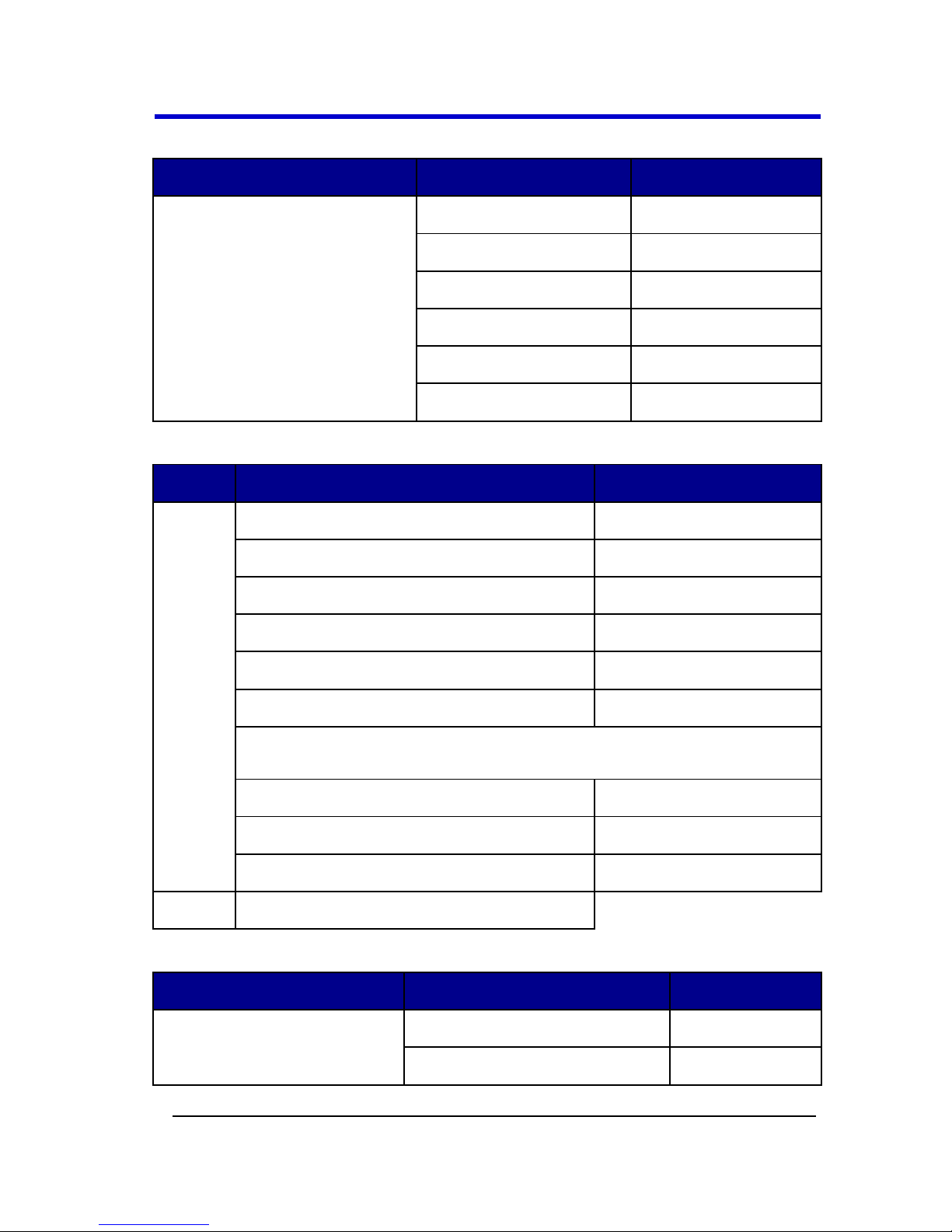
WaveAce 1000/2000
WA1K2K-OM-E RevB 71
The default settings made to the oscilloscope are detailed as follows:
Menu
Option
Default
CH1,CH2
(2 Channel Models)
CH1,CH2, CH3, CH4
(4 Channel Models)
Coupling
DC
BW Limit
Off
Volts/div adjust
Coarse (fixed)
Probe
1X
Invert
Off
Volts/div
1.00V
Menu
Option
Default
MATH
Operation (2 Channel Models)
CH1-CH2
Operation (4 Channel Models)
CH1-CH2, CH3-CH4
CH1 Invert
Off
CH2 Invert
Off
CH3 Invert (4 Channel Models)
Off
CH4 Invert (4 Channel Models)
Off
FFT Operation
Source
CH1
Window
Hanning
FFT Zoom
1X
Scale
dBVrms
Menu
Option
Default
HORIZONTAL
Window
Main
Position
0.00μs
Page 79

Operator's Manual
72 WA1K2K-OM-E RevB
Menu
Option
Default
Sec/div
500μs
Window Zone
50.0μs
Trigger Knob
level
Menu
Option
Default
CURSOR
Type
Off
Source
CH1
Horizontal (voltage)
±3.2divs
Vertical (time)
±5divs
Menu
Option
Default
MEASURE
Source
CH1
Type
average
Menu
Option
Default
ACQUIRE
Mode
Sampling
Averages
16
Menu
Option
Default
DISPLAY
Type
Vectors
Persist
Off
Grid
Menu Display
Infinite
Page 80

WaveAce 1000/2000
WA1K2K-OM-E RevB 73
Menu
Option
Default
REF
Type
Waveform
Source
CH1
Menu
Option
Default
TRIGGER (Edge)
Type
Edge
Source
CH1
Slope
Rising
Mode
Auto
Coupling
DC
Level
0.00V
Menu
Option
Default
TRIGGER (Pulse)
Type
Pulse
Source
CH1
When
=
Set Pulse Width
1.00ms
Mode
Auto
Coupling
DC
Menu
Option
Default
TRIGGER (Video)
Type
Video
Source
CH1
Polarity
Normal
Sync
All Lines
Page 81

Operator's Manual
74 WA1K2K-OM-E RevB
Menu
Option
Default
Standard
NTSC
Menu
Option
Default
TRIGGER (Slope)
Type
Slope
Source
CH1
Mode
Auto
Menu
Option
Default
TRIGGER (Slope)
Type
Alternative
Source
CH1
Using the SAVE ALL Screen
The SAVE ALL screen is divided into functions (New, Delete, Load, and
Rename) based on modifying a Directory or Files when saving items to a
USB memory device.
Note: The SAVE ALL screen opens showing Directorys by default. Press the
first Modify option button to toggle between Directory and Files menus.
The SAVE ALL - Directory Menu
Directory shows option buttons for New Dir., Del Folder, and Load.
Page 82

WaveAce 1000/2000
WA1K2K-OM-E RevB 75
Page 83

Operator's Manual
76 WA1K2K-OM-E RevB
The SAVE ALL - Files Menu
While Files shows option buttons for New File, Delete File, and Load.
Note: Use these File functions to save Setups, Waveforms, Pictures, and
Data.
Recalling Files
The Load button is used to recall your setup files. Once you've navigated
to the desired file and it's highlighted in the main screen area, press the
Load option button and the setup is recalled from the USB memory
device.
Page 84

WaveAce 1000/2000
WA1K2K-OM-E RevB 77
PLEASE NOTE THE FOLLOWING:
As shown in the previous screen-shot, the system warns you if you
try to load an incorrectly formatted file.
The Load option is disabled (grayed-out) when Pictures or CSV file
types are selected as Type.
The SAVE ALL Menu - Page 2/2
Both Directories and Files have Rename and Return option buttons on
Page 2/2. Use these buttons to give an existing folder or file a new name
or to exit the SAVE ALL screen, respectively.
Creating Folders and Files
Create new folders and files by pressing the New Folder or New File
option button. Also, when you select the Rename function for a Folder or
File, the following screen is shown.
Page 85

Operator's Manual
78 WA1K2K-OM-E RevB
The New File menu choices and behavior is the same as the New
Folder menu. It just has a different heading. The InputChar option
button adds the selected character to the cursor position in the
Name field.
Move the cursor position in the name field using the → and ←
option buttons.
Turn the Adjust Front Panel (on page 10) knob to move through
character selections. When the desired character is highlighted,
push the Adjust knob or press the InputChar option button to add
it to the specific position in the Name field.
Additional selections for BackSpace, DeleteCharacter, and
CleanName are available for convenience and are also accessed
using the Adjust knob in the same manner.
Press the Confirm option button (when you have the Name field
completed as desired) to rename or save the folder/file onto the memory
device.
After the Confirm option button is pressed, a Data Store Success!
message is briefly shown and the new Folder or File is saved and shown
on your memory device, if applicable.
The system notifies you if your folder or file name has reached the
character string limit.
Page 86

WaveAce 1000/2000
WA1K2K-OM-E RevB 79
Utilities
Utility Menu
You can use the Utility menu to configure your oscilloscope. Press the
UTILITY Front Panel (on page 10) button to display the Utility menu. The
first of four available pages containing various utility functions is shown.
The screens and functions are covered in the following sections.
Utility Menu - Page 1/4
1. Press the System Status option button to display a summary of
the oscilloscope settings.
Note: As indicated, press the SINGLE Front Panel (on page 10)
button to exit the System Status screen.
Page 87

Operator's Manual
80 WA1K2K-OM-E RevB
2. Press the Sound option button to turn tones On/Off as desired.
3. Turning the Frequency Counter On/Off shows or hides it from the
grid display.
4. Press the Language option button to choose the local language of
the user interface.
5. Press the Next Page option button to display page 2/4.
Page 88

WaveAce 1000/2000
WA1K2K-OM-E RevB 81
Utility Menu - Page 2/4
DO SELF CAL
1. Press the Do Self Cal option button to perform a self-calibration.
The Do Self Cal screen is shown.
2. As the screen indicates, disconnect anything plugged into input
connectors (except for the power cable) before pressing the
SINGLE Front Panel (on page 10) button and performing a selfcalibration. Press the RUN/STOP front panel button to exit the Do
Self Cal screen.
3. After pressing the SINGLE front panel button, a status bar shows
the self-calibration progress for each channel on the instrument.
Page 89

Operator's Manual
82 WA1K2K-OM-E RevB
Note: The system indicates which channel is being calibrated above
the progress bar.
4. Press the SINGLE front panel button when self-calibration is
complete.
DO SELF TEST
1. Press the Do Self Test option button to perform a self-test. A
separate SELF TEST screen is then shown.
Page 90

WaveAce 1000/2000
WA1K2K-OM-E RevB 83
Note: After using corresponding option buttons to choose Do Self Cal,
Do Self Test, or Print Setup (when enabled by selecting Printer on
the Back USB option button), you're taken to a separate menu based
on your selection where additional options are then shown. You can
always return to the original menu from this menu by pressing the
UTILITY front panel button.
Choose from Screen, Keyboard, or LED tests by pressing the
respective option button.
After making your selection a corresponding screen is shown
where either the SINGLE or RUN/STOP front panel button is used
to complete the test and/or exit the test screen, respectively.
Screen, Keyboard, and LED Test screens look like the following:
Page 91

Operator's Manual
84 WA1K2K-OM-E RevB
Screen Test - Each press of the SINGLE front panel button runs successively through
colors and is how the Screen Test is performed. Move through a few colors until you are
satisfied. As the screen indicates, press the RUN/STOP front panel button to exit.
Keyboard Test - As front panel buttons and knobs are pressed and turned, the screen
colorizes their corresponding location on the test screen, indicating correct function and
a successful test. Test all of the instruments buttons and knobs as desired. As the screen
indicates, pressing the RUN/STOP front panel button three times exits the keyboard
test.
LED Test - Each press of the SINGLE front panel button illuminates a front panel button
or knob and simultaneously colorizes their corresponding location on the test screen,
indicating correct function and a successful test. As the screen-shot shows, the test
starts with the Intensity/Adjust knob. Test as many LEDs as desired. As the screen
indicates, press the RUN/STOP front panel button to exit.
Page 92

WaveAce 1000/2000
WA1K2K-OM-E RevB 85
PRINT SETUP
1. Press the Print Setup... option button to set up your print options.
A separate Print screen is then shown (Page 1/2).
PLEASE NOTE THE FOLLOWING:
Only when the Back USB option button (covered in the next
step) is set to Printer is the Print Setup... option button
enabled for use.
After using corresponding option buttons to choose Do Self
Cal, Do Self Test, or Print Setup (when enabled by selecting
Printer on the Back USB option button), you're taken to a
separate menu based on your selection where additional
options are then shown. You can always return to the
original menu from this menu by pressing the UTILITY front
panel button.
When printing, make sure your printer is connected to the
back of your WaveAce oscilloscope as covered in Back and
Side Connections (on page 10).
For more information, see Print Setup (on page 88).
BACK USB
Press Back USB and choose either Computer or Printer as desired based
on what you connect to your instrument using the USB Type B
Receptacle on the back of the oscilloscope as covered in Back and Side
Connections (on page 10).
Press the Next Page option button to display page 3/4.
Page 93

Operator's Manual
86 WA1K2K-OM-E RevB
Utility Menu - Page 3/4
1. Press the Update Firmware option button to update the
oscilloscope using the USB memory device. For more information,
see the Updating the System Software (on page 90) section.
2. Pressing the Pass/Fail option button shows the Pass/Fail menu
where you can monitor changes of signals and output pass or fail
signals by judging whether the input signal is within the
predefined mask. For more information, see Using Pass/Fail (on
page 93).
3. Pressing the Record option button shows the Record menu where
you can record the input waveform from CH1 and CH2 (also, CH3
and CH4 on four channel versions), with a maximum record length
of 2500 frames.
You can record Pass/Fail test output (especially useful when
capturing abnormal signals over a long period of time) without
having to watch the signal.
Just set the source, the time interval between record frames, and
the maximum number of record frames. For more information,
see Using Record (on page 96).
4. With your oscilloscope connected to your network, pressing the IP
Setting option button shows Internet Protocol values for your
specific IP Address, Subnet Mask, Gate Way, Port, Mac Address,
and DHCP.
Page 94

WaveAce 1000/2000
WA1K2K-OM-E RevB 87
Use the top/first Menu Option button to move through
IP Address, Subnet Mask, Gate Way, and DHCP controls. Push the
Adjust Front Panel (on page 10) knob to move within a control
and turn the knob to change values.
Note: As indicated, press the Save/Recall Front Panel (on page 10)
button to save any adjusted values and the SINGLE button to exit the
IP Setting screen.
5. Press the Next Page option button on Utility Menu - Page 3/4 to
show page 4/4.
Utility Menu - Page 4/4
1. Press the Screen saver option button to choose from various time
lengths before the oscilloscope display goes blank and enters
Page 95

Operator's Manual
88 WA1K2K-OM-E RevB
screen saver mode. Time length options include 1min , 2min,
5min, 10min, 15min, 30min, 1hour, 2hour, 5hour and Off. Of
course, selecting Off keeps the oscilloscope from entering screen
saver mode entirely.
2. Pressing the Date/Time option button shows the Date/Time menu
where you can make this setting and choose to show it on the
lower-right of your display. For more information, see Setting and
Displaying the Date/Time (on page 100).
3. Press the Quick-Cal option button to turn quick calibration On or
Off.
4. Press the USB Speed option button to select from Full or High
Speed transfer options for the Back USB connector. See, Back and
Side Connections (on page 10) for more information.
5. Press the Next Page option button to display page 1/4.
Print Setup
PLEASE NOTE THE FOLLOWING:
As explained in Utility Menu (on page 79), only when the Back
USB option button is set to Printer is the Print Setup... option
button enabled for use.
Your printer may override these setup selections to ensure the
best fit. If selections are not supported by your printer, the
oscilloscope uses the Default setting.
Most USB printers supporting direct printing through Type A USB
port connections are compatible with your WaveAce oscilloscope.
Refer to your printer's product documentation to verify
compatibility.
Print - Page 1/2
After pressing the enabled Print Setup option button, the first of two
PRINT menus (Page 1/2) is shown and contains the following option
button controls.
Page 96

WaveAce 1000/2000
WA1K2K-OM-E RevB 89
Ink Saver - Turn this option button control On or Off to help save
ink on your printer (if you have one) connected to the back of your
instrument.
Layout - Choose from Portrait or Landscape print layouts as
desired.
Paper Size - Choose from Default, L, 2L, Hagaki Postcard, Card
Size, 10 x 15cm, 4" x 6", 8" x 10", Letter, 11" x 17", A0-9, B0-9,
89mm Roll(L), 127mm Roll(2L), 100mm Roll(4"), and 210mm
Roll(A4).
Print Key - Select whether a picture is saved to a USB memory
device or printed when the PRINT menu control button is pressed.
Next Page - Use this option button to show Page 2/2.
Print - Page 2/2
After pressing Next Page from Page 1/2, the second of two PRINT menus
(Page 2/2) is shown and contains the following option button controls.
Page 97

Operator's Manual
90 WA1K2K-OM-E RevB
Image Size - Choose from Default, 2.5x3.25 in, L (3.5x5 in), 4x6 in,
2L (5x7 in), 8x10 in, 4L (7 x 10 in), E, Card, Hagaki card, 6 x 8 cm,
7x10 cm, 9x13 cm, 10x15 cm, 13x18 cm, 15x21 cm, 18x24 cm, and
A4, Letter
Paper Type - Choose from Default, plain, Photo, and Fast Photo.
Print Quality - Choose from Default, Normal, Draft, and Fine.
ID Print - Choose from Default, On, and Off.
Next Page - Use this option button to show Page 1/2.
If desired, press the Utility Front Panel (on page 10) button and the
Utility menu is shown.
Updating the System Software
LeCroy periodically releases software updates for the WaveAce providing
new features, enhancements, and software corrections. These updates
are available for download from the LeCroy website at www.lecroy.com.
After registering your product, you can select the appropriate download
based on your specific WaveAce oscilloscope model.
Page 98

WaveAce 1000/2000
WA1K2K-OM-E RevB 91
After downloading, open the .zip file on your computer. The .zip should
contain an .ads file and the Firmware Update Procedure .pdf file.
Move the .ads file to a USB memory device.
The system software update .ads file is then loaded through the USB
memory port on the front of the oscilloscope.
1. Insert the USB memory device containing the software update in
the USB port on the front of the oscilloscope.
2. Press the front panel Utility button.
3. Press the Next Page menu option button to navigate to menu
page 3/4. Select the Update Firmware menu option button. The
Update Firmware screen is shown.
Note: Verify the firmware product type matches your instrument. Also,
verify the firmware update file is stored in the root directory of the
USB memory device.
Page 99

Operator's Manual
92 WA1K2K-OM-E RevB
Press the SINGLE front panel button to begin loading the .ads
firmware update file from your USB memory device Using the
SAVE ALL Screen (on page 74). Otherwise, press the RUN/STOP
front panel button to exit the Update Firmware screen.
Locate the .ads firmware update file, select it, and then press the
Load option button. The following status screen is shown.
The oscilloscope then beeps aloud twice and shows a screen
stating - The firmware has been updated completely, please boot
up the DSO again. At this point, turn your oscilloscope power Off,
wait a short while, and then power it On again.
When the oscilloscope has rebooted, your update is complete.
Page 100

WaveAce 1000/2000
WA1K2K-OM-E RevB 93
Using Pass/Fail
The Pass/Fail function monitors signal changes determining whether or
not it falls within a predefined mask.
Access Pass/Fail by pressing the corresponding option button on the
Utility menu. The first of two Pass/Fail menus is then shown.
Pass/Fail - Page 1/2
After pressing the Pass/Fail option button, the first of two Pass/Fail
menus (Page 1/2) is shown and contains the following option button
controls.
1. Press the Enable Test option button to turn the function On or
Off.
 Loading...