

Page 1
PROTOCOL SOLUTIONS GROUP
3385 SCOTT BLVD
SANTA CLARA, CA 95054
LeCroy UWBTracer™/Trainer
Ultra-Wideband Protocol Analyzer
User Manual
Manual Version 3.0
™
For Software Version 3.0
August 2007
Page 2

UWBTracer/Trainer User Manual
Document Disclaimer
The information in this document has been carefully checked and is believed to be
reliable. However, no responsibility can be assumed for inaccuracies that may not have
been detected.
LeCroy reserves the right to revise the information in this document without notice or
penalty.
Trademarks and Servicemarks
LeCroy, UWBTrainer, UWBTracer, UWBTracer MPI, CATC Trace, and BusEngine are
trademarks of LeCroy.
Microsoft and Windows are registered trademarks of Microsoft Inc.
Intel and Pentium are registered trademarks of Intel Corporation.
AMD Duron and AMD Athlon are trademarks of Advanced Micro Devices, Inc.
All other trademarks are property of their respective companies.
Copyright
Copyright © 2007, LeCroy Corporation. All Rights Reserved.
This document may be printed and reproduced without additional permission, but all
copies should contain this copyright notice.
FCC Conformance Statement Compliance with
47 CFR 15.519 (a)(1)
This device complied with Part 15 of the FCC Rules. Operation is subject to the following
two conditions: (1) This device may not cause harmful interference, and (2) this device
must accept any inter ferenc e rece ived, inclu ding interfer ence that may cau se undesired
operation.
FCC Rule 47 CFR 15.519 (a)(1) states that “A UWB device operating under the
provisions of this section shall transmit only when it is sending information to an
associated receiver. The UWB intentional radiator shall cease transmission within
10 seconds unless it receives an acknowledgement from the associated receiver that its
transmission is being received. An acknowledgement of reception must continue to be
received by the UWB intentional radiator at least every 10 seconds or the UWB device
must cease transmitting. “
This equipment may only be operated indoors. Operation outdoors is in violation of
47 U.S.C. 301 and could subject the operator to serious legal penalties.
Note: This device must be installed in a location that is not accessible to the general
public. Install the device so that the antenna is more than 20 cm from unsuspecting
personnel. Failure to install this device as described will result in a failure to comply with
FCC rules for RF exposure and is discouraged. Only antennas approved with the device
may be used. This device may not be co-located with other transmitters without further
approval by the FCC.
Caution: Changes or modifications not expressly approved by the party responsible for
compliance could void the operator’s authority to operate the equipment.
LeCroy Corporation
Page 3

UWBTracer/Trainer User Manual
EU Declaration of Conformity
This equipment including all its options is in conformity with the provisions of the following
EC directives(s), including all the latest amendments:
73/23/EEC Low Voltage Directive
89/336/EEC EMC Directive
Conformity with Council Directive 73/23/EEC is based on:
EN 61010-1: 2001 Safety requirements for electrical equipment for measurement,
control and laboratory use
Conformity with Council Directive 89/336/EEC is based on:
EN 61326/A3: 2003 EMC requirements for electrical equipment for measurement
control and laboratory use
Emissions EN 55011/A2:2002 (Conducted and Radiated Emissions)
Immunity EN 61000-4-2/A2:2001 (Electrostatic Discharge)
EN 61000-3-2/A2:2005 (Harmonic Current Emissions)
EN 61000-3-3/A2:2005 (Voltage Fluctuations and Flicker)
EN 61000-4-3/A1:2003 (RF Radiated Electromagnetic Field)
EN 61000-4-4:2004 (Electrical Fast Transient/Burst)
EN 61000-4-5/A1:2001 (Surge)
EN 61000-4-6/A1:2001 (RF Conducted Electromagnetic Field)
EN 61000-4-11:2004 (Mains Dips and Interruptions)
Warning: This is a Class A product. In a domestic environment this product may cause
radio interference, in which case the user may be required to take adequate measures.
LeCroy Corporation
Page 4

WEEE Program
This electronic product is subject to
disposal and recycling regulations that
vary by country and region. Many
countries prohibit the disposal of
waste electronic equipment in
standard waste receptacles.
For more information about proper
disposal and recycling of your LeCroy
product, please visit
www.lecroy.com/recycle.
Part number: 730-0077-00
UWBTracer/Trainer User Manual
LeCroy Corporation
Page 5

UWBTracer/Trainer User Manual Section 1
Section 1. General
LeCroy Corporation 1
Page 6

Section 1 UWBTracer/Trainer User Manual
[blank page]
2 LeCroy Corporation
Page 7

UWBTracer/Trainer User Manual Chapter 1: Overview
Chapter 1: Overview
This chapter describes the UWBTracer/Trainer™ product and Ultra-Wideba nd
technology in general.
1.1 UWBTracer/Trainer Ultra-Wideband Analyzers
The LeCroy UWBTracer/Trainer is a portable Ultra-Wideband (UWB) test and debug
platform that combines non-intrusive recording with extensive decoding features. The RF
(wireless) recording functionality is designed to record non-intrusively off-the-air WiMedia
UWB traffic from one or more devices, while the MPI recording functionality is designe d
to connect to the specification-defined MAC-PHY Interface (MPI) bus between the MAC
and the PHY subsystems in WiMedia-compliant devices and to capture the traffic
between them. The WiNet protocol uses the MUX sublayer and services of the WiMedia
MAC for data networking.
By leveraging years of experience in protocol analysis tools for emerging markets,
UWBTracer/Trainer blends sophisticated functionality with practical features to allow
designers and validation engineers to easily specify multi-level, conditional trigger
scenarios to pinpoint intermittent problems in the UWB connection.
System-level validation requires non-intrusive monitoring. UWBTracer/Trainer ensures
accurate data collection by providing transparent electrical taps. At the heart of
UWBTracer/Trainer is the CATC BusEngine™ protocol processor that features a
real-time recording engine for UWB MAC-to-PHY tra ffic.
UWBTracer/Trainer also supports remote operation over a LAN and unattended control
of the analyzer with an Automation API. UWBTracer/Trainer includes an advanced
search capability that allows to search for specific fields in the recorded trace and to
navigate faster to places of interest inside the trace.
UWBTracer/Trainer fe atures a real-time st atistics display that continuo usly monitors and
presents metrics for the recorded MAC-to-PHY traffic, providing a hig h -leve l view of
network performance.
For complete product information, please visit www.LeCroy.com.
LeCroy Corporation 3
Page 8

Chapter 1: Overview UWBTracer/Trainer User Manual
Table 1.1 summarizes key UWBTracer/Trainer features.
Table 1.1 UWBTracer/Trainer Features
Feature Benefit
Wireless capturing & recording Allows off-the-air (and non-intrusive) recording of UWB
traffic
MPI capturing & recording Probes the WiMedia specification-defined bus between the
MAC and PHY layers, while remaining non intrusive.
Suitable for three different popular connector types.
Simultaneous RF and MPI
recording
Advanced Triggering Robust capability of setting complex triggering and filtering
Trace View Comprehensive viewing of the recorded traffic with
Advanced search Fast and comprehensive trace searches.
Collapsible/expandable header Increased drill-down on exchanges, sequences, or individual
Real-time performance monitoring
and statistics
Dynamically-allocated memory
pool
Interchangeable Radios and room
for future expansion
WiNet protocol
Capable of recording one RF and one MPI channel at the
same time and display a combined trace
sequences and act in real-time on those settings on each of
the channels.
convenient customization through the trace display options.
frames.
Allows easy identification of throughput problems and
anomalies.
(2 GB) Captures long time-windows for analysis and
problem-solving.
The modular design of the UWBTracer
CATC 5K platform permits interchanging modules and
radios
/Trainer™ and the
Uses the MUX sublayer and services of the WiMedia
MAC for data networking
4 LeCroy Corporation
Page 9

UWBTracer/Trainer User Manual Chapter 1: Overview
1.2 Ultra-Wideband Technology
UWB technology was available for over 40 years for military and civilian applications and
was originally called either impulse radio or carrier-free communications. Today, the FCC
definition for UWB is any radio technology with a spectrum that occupies greater than 20
percent of the center frequency or a minimum of 500MHz.
In 2002, the FCC allocated unlicensed radio spectrum from 3.1 GHz to 10.6 GHz
expressly for enterprise and consumer applications. The FCC defined a specific
minimum bandwidth of 500 MHz at a -10dB level. As current UWB implementations allow
communication that requires high data rates over short distances, one immediate UWB
application is WPAN (Wireless Personal Area Network).
The Multi-band OFDM technology, promoted by the WiMedia Alliance, is one of the
technologies that can utilize the allocated band for UWB. The MB-OFDM transmits data
simultaneously over multiple carriers spaced apart at precise fr equencies. This approach
provides benefits like high spectral flexibility and resiliency to RF interference and
multi-path effects.
The WiMedia UWB specifications are available from the WiMedia Alliance. The URL for
the WiMedia website:
http://www.wimedia.org
1.3 WiMedia UWB Specification Ecosystem
The WiMedia Alliance has developed specifications for ultra-wide-band (UWB) devices.
The main goal of the WiMedia UWB specifications is to create a UWB “ecosystem” that
allows easy and secure operation of UWB devices.
The WiMedia UWB specifications have a first-generation data rate of 480 Mbps, which
enables a multitude of innovative wireless devices. UWB devices that follow the
WiMedia UWB specifications can co-exist in the same physical environment, even if they
have unrelated applications.
Markets for two major application types are emerging:
• Certified Wireless-USB (WUSB)
• WiNet
LeCroy Corporation 5
Page 10

Chapter 1: Overview UWBTracer/Trainer User Manual
1.3.1 Certified Wireless USB Overview
The WiMedia UWB specification first-generation data rate of 4 80 Mbp s provides a basis
for delivering WUSB devices that can perform comparably with USB 2.0 devices.
The Certified Wireless-USB protocol maintains the same host-device model as the wir ed
USB protocol, but the Certified Wireless-USB protocol ma ke s ma ny optimizations for
operating efficiently on a wireless medium.
The first Certified Wireless-USB-protocol products are various Wire Adapter devices,
which operate as wired-to-wireless bridges. Host Wire Adapters (HWA) enable any PC
with USB 2.0 to become a WUSB Host. Device Wire Adapters (DWA) are wireless hubs
that can connect wired USB 2.0 devices to a WUSB Host.
For Certified Wireless-USB-protocol devices, UWBTracer/Trainer provides full protocol
decoding from low-level packets to high-level Wire Adapter transfers.
The WUSB specification is available from the USB Implementers Forum (USB-IF). The
URL for the USB-IF website is:
http://www.usb.org/home
1.3.2 WiNet Overview
WiNet is a protocol that uses the services of the WiMedia MAC for data networking.
The WiNet protocol uses the MUX sublayer and service defined in the WiMedia MAC
specification. The MUX sublayer combined with the WiNet protocol corresponds to the
logical link control sublayer of the standard ISO/OSI IEEE 802 reference model.
For more information about the WiNet protocol, MUX sublayer and service, and WiMedia
MAC specification, see the WiNet specification at www.WiMedia.org.
6 LeCroy Corporation
Page 11

UWBTracer/Trainer User Manual Chapter 2: Hardware Description
Chapter 2: Hardware Description
This chapter describes the CATC 5K-based UWBTracer/Trainer™ Analyzer and
Exerciser and other components and accessories that accompany it.
2.1 CATC 5K Platform
CATC 5K Platform
The CATC 5K is a lightweight and modular platform, designed to be mobile and flexible.
The two front slots can accommodate up to two plug-in modules with a variety of options.
The CATC 5K platform is powered by a small external power supply. Quiet built-in fans
provide all the necessary cooling.
Connection to Host Machine
The CA TC 5K platform conn ects to a Windows®-based PC (the host machine) through a
single USB cable. Though the system can operat e over USB 1.1 protocol data rates, it is
advisable to use a USB 2.0 connection between the Analyzer and the host machine to
obtain faster upload of traffic.
2.2 UWBTracer/Trainer Analyzer and Exerciser
The basic UWBT racer/Trainer analyzer configuration includes a CA TC 5K plat form and a
UWB Analyzer plug-in module (UW002MA or UW003MA) that is inserted into the
right-side slot.
In addition, the USB Analyzer plug-in module (US007MA) can be inserted into the
left-side slot and be used for capturing USB Association traffic, retrieving the information
required for pairing two WUSB devices. See “USB Cable Association for Certified WUSB”
on page 212 for more information.
The UWB Exerciser plug-in module can be inserted into the lef t-side slot and be used for
traffic generation.
LeCroy Corporation 7
Page 12
Chapter 2: Hardware Description UWBTracer/Trainer User Manual
2.3 System Components
Basic Components
The UWBTracer/Trainer™ basic package includes the following components:
• Installation CD-ROM, with the installation program and all documents
• UWBTracer/Trainer Getting Started manual, to help set up the system quickly
• CATC 5K Platform: See photograph on front cover. Also see “CATC 5K Front Panel
with the UWB Analyzer Plug-in” on page 14 and “CATC 5K Rear Panel” on page 18.
• CATC 5K Power Supply and Power Cord
•Carrying case
• Vertical Stand
Figure 2.1 Vertical Stand
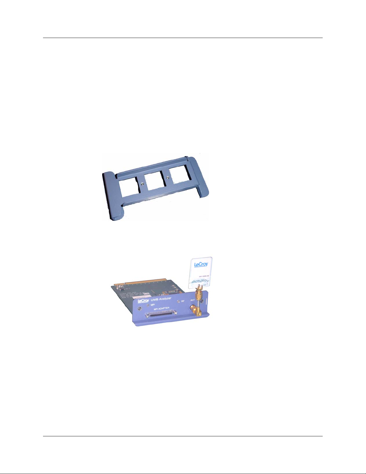
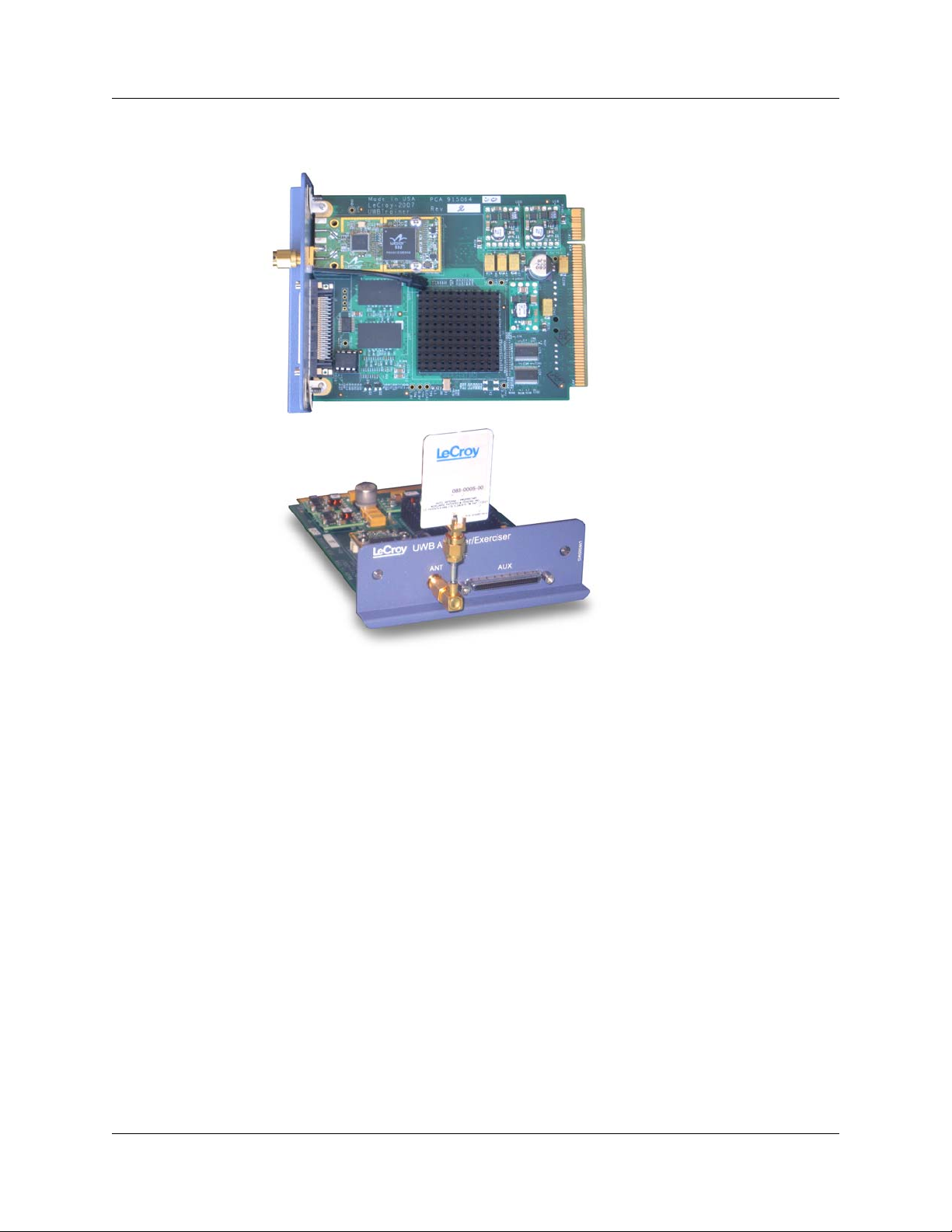
• UWB Analyzer Module and RF Antenna
Figure 2.2 UWB Analyzer Plug-in Module with Antenna (UW002MA or
UW003MA)
8 LeCroy Corporation
Page 13
UWBTracer/Trainer User Manual Chapter 2: Hardware Description
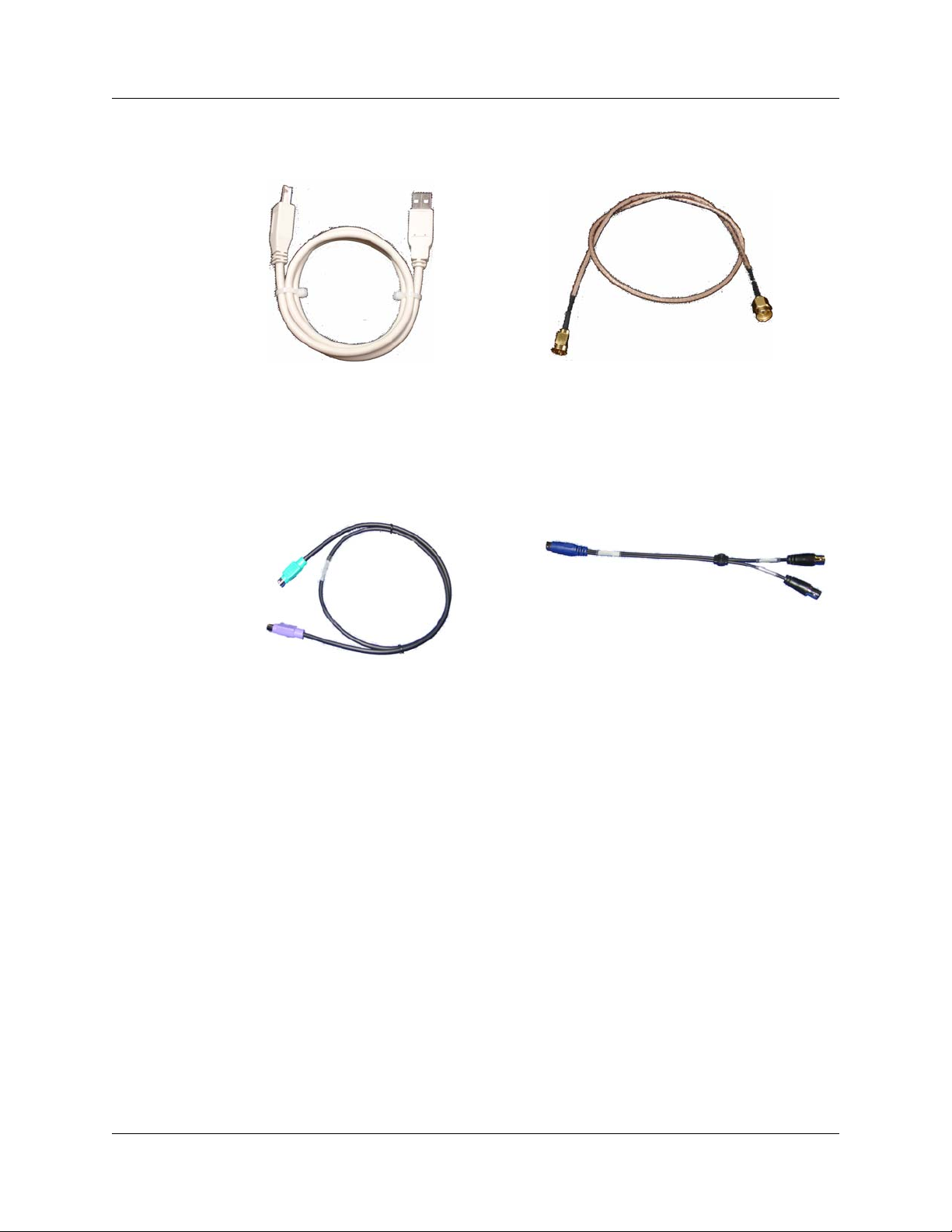
• RF Coaxial Cable (SMA) [in Standard Cable Kit]
• USB cable for connecting the analyzer to a host machin e
Figure 2.3 USB cable and RF Coaxial Cable (SMA)
• Synchronization Cable for synchronizing multiple analyzers. The Synchroniza tion
Cable connects to the SYNC IN and SYNC OUT connectors located on the
UWBTracer/Trainer rear panel (Figure 2.15). (For more information about setting up
multiple analyzers, see Section 10.3, “Multiple Analyzer Synchronization” on page
152.)
Figure 2.4 Synchronization Cable and Trigger Cable
• Trigger Cable (TRIG-IN/TRIG-OUT BNC Y-cable) for connecting to external equip-
ment (for example, for triggering capturing in a LeCroy oscilloscope).
LeCroy Corporation 9
Page 14
Chapter 2: Hardware Description UWBTracer/Trainer User Manual
Optional Components
In addition to the basic package, optional components ar e available:
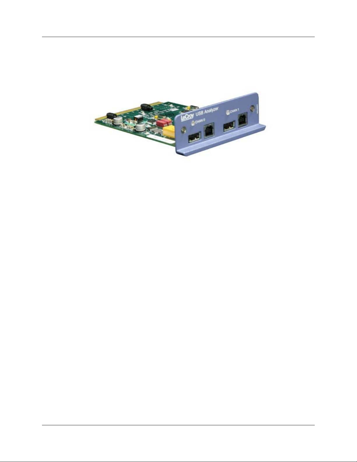
• USB Analyzer plug-in module for capturing USB Cable Association traffic
(US007MA)
Figure 2.5 USB Analyzer Plug-in Module (US007MA)
• UWB Analyzer plug-in module with PHY (radio) from a different vendor
(UW002MA or UW003MA)
[see Figure 2.2]
• MPI Kit (please refer to the Data Sheet for detailed information)
[see next page]
10 LeCroy Corporation
Page 15
UWBTracer/Trainer User Manual Chapter 2: Hardware Description
•UWBTrainer Exerciser plug-in module and RF Antenna
Figure 2.6 UWB Exerciser Plug-in Module with Antenna (UW005MGA)
LeCroy Corporation 11
Page 16
Chapter 2: Hardware Description UWBTracer/Trainer User Manual
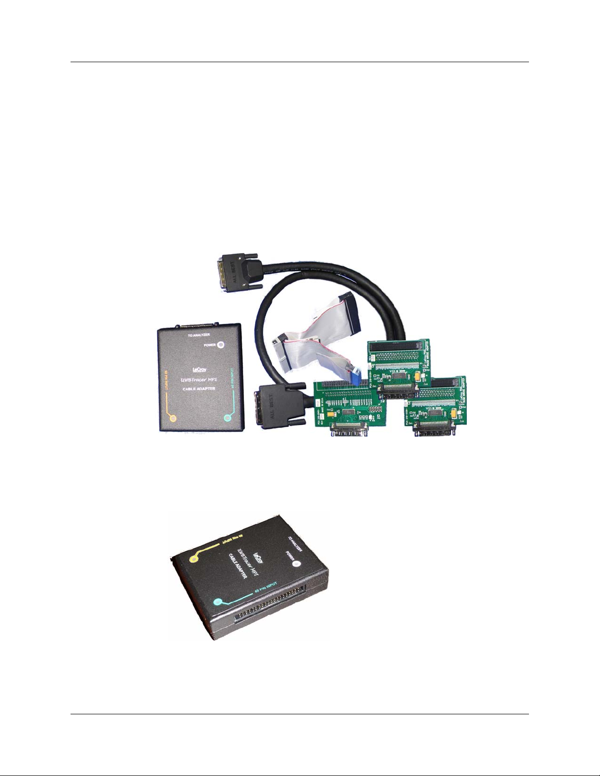
MPI Kit
The MPI kit is designed for hooking to the MPI bus in two types of setups:
1. PHY subsystem connects to the MAC subsystem through a short (ribbon) cable.
2. PHY subsystem piggybacks directly on the MAC subsystem. The two subsystems
connect through an adapter board without the use of cables.
Three types of connectors are common for current designs:
1. IDE 40-pin connector
2. Hirose 68-pin Connector
3. Hirose 60-pin Connector
The optional MPI Kit includes:
Figure 2.7 MPI Kit
• Cable Adapter
Figure 2.8 Cable Adapter for Hirose 68-pin or IDE 40-pin Connectors
for Hirose 68-pin or IDE 40-pin Connectors
12 LeCroy Corporation
Page 17
UWBTracer/Trainer User Manual Chapter 2: Hardware Description
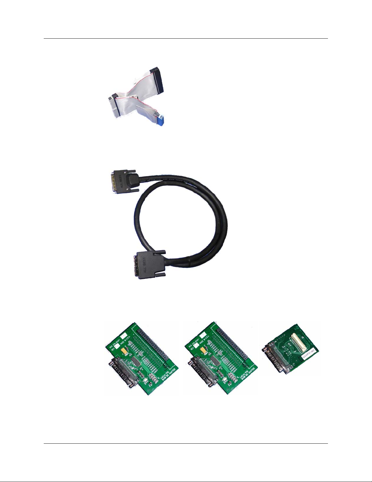
• Probe Cable for IDE 40-pin Connectors and Hirose 68-pin Connectors (2)
Figure 2.9 Probe Cable for IDE 40-pin Connectors and
Hirose 68-pin Connectors
• Adapter Cable
Figure 2.10 Adapter Cable (with external SCSI type connectors)
•
Board Adapter for IDE 40-pin Connectors, Board Adapter for Hirose 68-pin Connectors, and
Board Adapter for Hirose 60-pin Connectors
Figure 2.11 Board Adapter for IDE 40-pin Connectors,
Board Adapter for Hirose 68-pin Connectors, and
Board Adapter for Hirose 60-pin Connectors
LeCroy Corporation 13
Page 18
Chapter 2: Hardware Description UWBTracer/Trainer User Manual
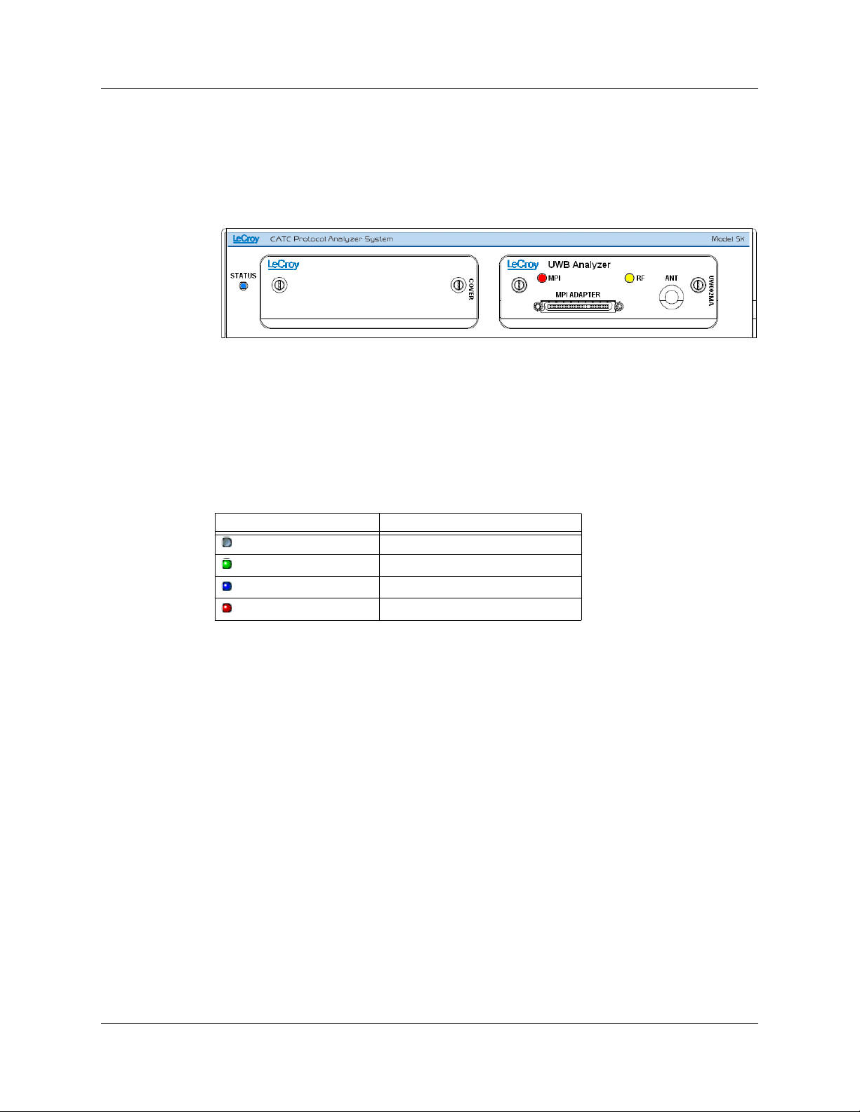
2.4 UWBTracer/Trainer Front Panel Description
When powered ON, the CA TC 5K Analyzer activates user- accessible controls and LEDs
on front and rear panels of the plat form. This section covers front panel features. Th e next
section covers rear panel features.
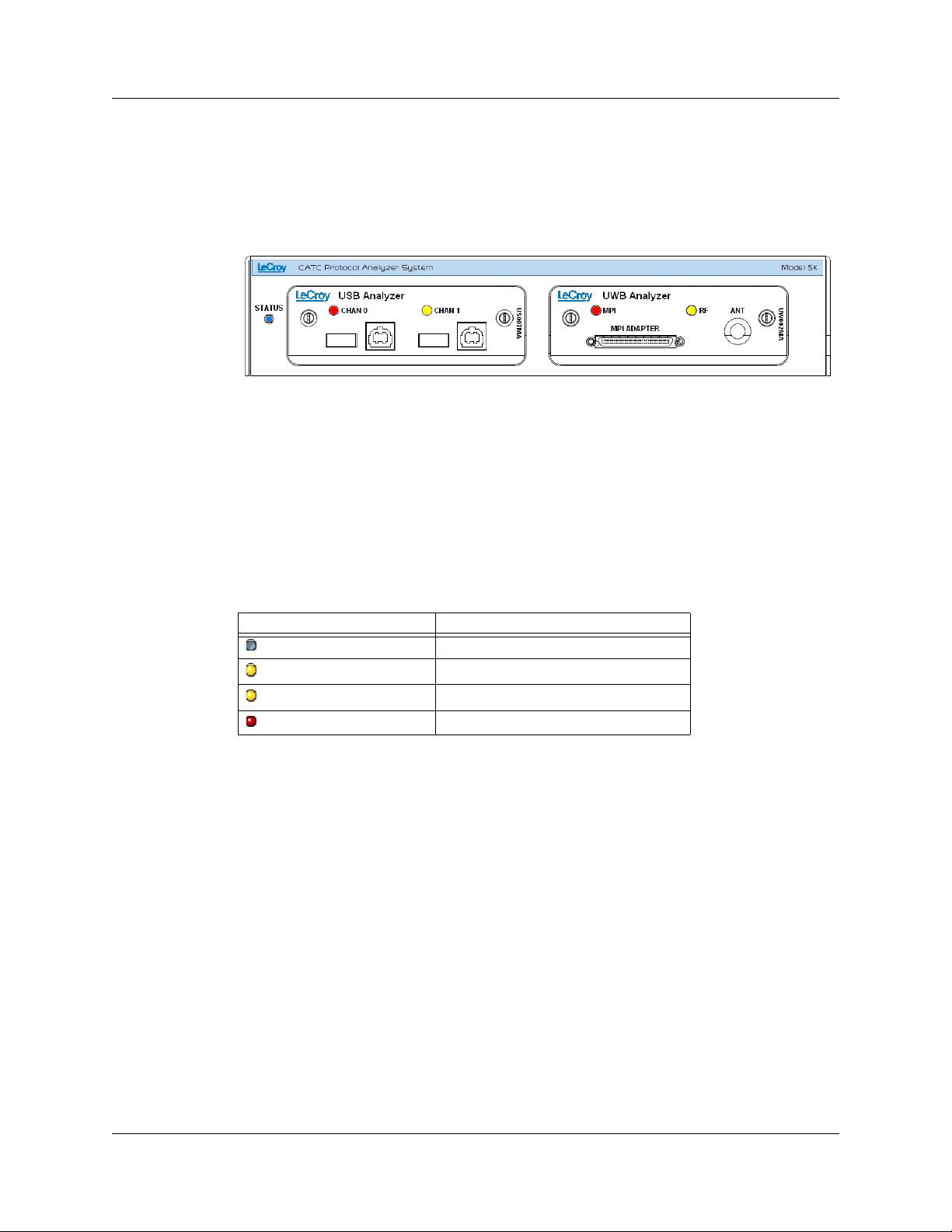
Figure 2.12 CATC 5K Front Panel with the UWB Analyzer Plug-in
CATC 5K Platform
The indicators on the CATC 5K platform (Figure 2.12) are:
STATUS (status of the platform)
LED Description
No light
Green Blink Slow
Blue
Red Blink Fast
System is not powered on
Initializing
System is operational
System fault (contact Support)
14 LeCroy Corporation
Page 19

UWBTracer/Trainer User Manual Chapter 2: Hardware Description
UWB Analyzer Plug-in Module
LEDs (status of the MPI or RF channel)
LED State MPI Channel RF Channel
No light
Yellow Blink Fast
Yellow
Red Blink Slow
Red
Idle Does not detect PCLK or
PHY_ACTIVE
Synching
Synched
Recording
Pre-Trigger
Recording
Post-Trigger
Trying to synchronize to
MPI traffic and waiting for
PCLK and PHY_ACTIVE
Synchronized:
Capturing MPI traffic with
PHY_ACTIVE signal high
Recording
Pre-Trigger traffic
Recording
Post-Trigger MPI traffic
Does not detect wireless
frames
Trying to synchronize to
RF traffic and waiting for
wireless traffic
Synchronized:
Capturing wireless frames
Recording
Pre-Trigger traffic
Recording
Post-Trigger wireless
traffic
Connectors
The connectors are:
• MPI ADAPTER: Connector to MPI Adapter
• ANT: SMA Connector for Antenna
LeCroy Corporation 15
Page 20
Chapter 2: Hardware Description UWBTracer/Trainer User Manual
USB Analyzer Plug-in Module for the
Cable Association
USB
In the UWBTracer/Trainer™ setup, the USB Analyzer plug-in module is used to capture
USB Association traffic between pairs of WUSB devices that support the
USB Cable Association Model described in the Certified Wireless USB specifications.
Figure 2.13 CATC 5K Front Panel with the UWB Analyzer and
USB Analyzer Plug-in
USB Cable Association traffic capture uses CHAN 0 of the module.
The second channel, marked CHAN 1, is for future expansion.
For instructions on how to set up and capture USB Cable Association traf fic and use it for
UWB traffic recording, see “USB Cable Association for Certified WUSB” on page 212.
LEDs (status of the USB Chan 0 channel)
LED State
No light
Yellow Blink Slow
Yellow Blink Fast
Red Blink Fast a few times
Note: For USB Chan 1, the LEDs are turned of f because they are n ot used for the
USB Cable Association traffic capture.
Idle
Synched to Full/Low speed USB traffic
Synched to High speed USB traffic
Connection Context traffic detected
Connectors
The connectors are:
• CHAN 0 USB PORTS: For capturing USB Cable Association traffic
• CHAN 1 USB PORTS: Not currently used
16 LeCroy Corporation
Page 21
UWBTracer/Trainer User Manual Chapter 2: Hardware Description
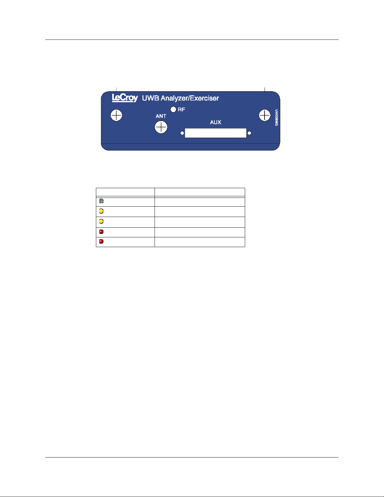
UWB Exerciser Plug-in Module
When powered ON, the UWB Exerciser activates user-accessible controls and LEDs on
front and rear panels of the platform. This section covers front panel features. The next
section covers rear panel features.
Figure 2.14 UWB Exerciser Plug-in Module
LEDs (status of the Exerciser RF channel)
LED State
No light
Yellow Blink Fast
Yellow Blink Slow
Yellow Solid
Red Solid
Idle
Scenario running
Scenario waiting for condition
Scenario paused
Scenario error
Connectors
The connectors are:
• ANT: SMA Connector for Antenna
• AUXILIARY: Connector
LeCroy Corporation 17
Page 22
Chapter 2: Hardware Description UWBTracer/Trainer User Manual
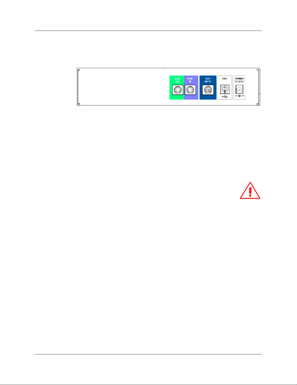
2.5 UWBTracer/Trainer Rear Panel Description
From left to right, the rear panel contains the following components:
Figure 2.15 CATC 5K Rear Panel
• SYNC IN/OUT: For synchronized multi-analyzer operation, the analyzers must be
connected in a daisy-chain topology to each other using the green/purple cable.
• EXT DATA: For attaching the TRIG-IN/TRIG-OUT BNC Y-cable (Trigger Cable) to
external instruments
• HOST: For connecting the analyzer through USB to the host machine
• POWER 12 VDC: For connecting the external power supply to the analyzer.
Note: There is no power switch on the analyzer.
Warning! Do not open the CATC 5K enclosure. No operator
serviceable parts are inside. Refer servicing to LeCroy.
2.6 Interchangeable Radios
Because WiMedia UWB specifications and technology are still evolving, a
UWBTracer/Trainer™ analyzer (with its CATC 5K platform) can use interchangeable
plug-in modules, each incorporating different PHYs (radios).
Currently there are two UWB Analyzer plug-in mod ules th at ca n be use d with the
UWBTracer: model UW002MA and model UW003MA.
Please note that each UWB Analyzer plug-in module requires different initialization
sequences that are executed according to a script that must be downloaded to the
analyzer using the Analyzer Setup menu and window, as described in Section 16.4,
“BusEngine, Firmware, and Plugin Init Updates” on page 262.
After you plug the module into the correct slot and check that you have the correct
BusEngine, Firmware, and initialization script installed, you can record traces.
18 LeCroy Corporation
Page 23

UWBTracer/Trainer User Manual Section 2
Section 2. UWBTracer/Trainer Analyzer
Software
LeCroy Corporation 19
Page 24

Section 2 UWBTracer/Trainer User Manual
[blank page]
20 LeCroy Corporation
Page 25

UWBTracer/Trainer User Manual Chapter 3: Software Overview
Chapter 3: Software Overview
The UWBTracer/Trainer™ software can:
• Control recording of UWB traffic.
• Manage one or more Analyzers, which can be connected directly to the host
machine or connected through the Analyzer network.
• View, analyze, and create reports about recorded traces.
3.1 Installing the Software
For instructions about installing the software, refer to the
UWBTracer/Trainer Ge tting Started manual.
3.2 Starting the UWBTracer/Trainer /Trainer Program
Y ou can use the UWBT racer/T rainer /T rainer with or without the analyzer unit. When used
without an analyzer , the program works as a trace viewer to view , analyze, and print trace
files.
To start the UWBTracer/Trainer /Trainer Program from the PC Start menu:
Step 1 Select Start > Programs > LeCroy > UWBTracer >
LeCroy UWBTracer
to display the application main window (Figure 3.1).
Figure 3.1 UWBTracer/Trainer Main Window
LeCroy Corporation 21
Page 26

Chapter 3: Software Overview UWBTracer/Trainer User Manual
3.3 Opening Sample Traces
A good way to gain familiarity with UWBTracer/Trainer is to open some of the provided
sample files and explore the menus, pop-up menus, and report s.
3.4 Opening Older Trace Files
The UWBTracer/Trainer software has the capacity to open trace files created with earlier
software versions. When an older trace file is opened, the program prompts you to
convert the file to the current software version.
3.5 Tool Tips
Throughout the application, Tool Tips provide useful information about bu tt on s on the
toolbar.
To display a Tool Tip, position th e mouse p ointer over an ite m of interest such as p a rt of
the trace or a button (Figure 3.2).
Figure 3.2 Tool Tip
3.6 Trace Tool-Tips
Many fields within the Trace display tool-tips when the mouse pointer is suspen ded over
them. These tips may provide a simple legend for the cell or may give substantial added
details about the field (Figure 3.3).
Figure 3.3 Trace Tool Tip
22 LeCroy Corporation
Page 27

UWBTracer/Trainer User Manual Chapter 3: Software Overview
3.7 Menu Bar
Table 3.1 lists menus available from the Main window menu bar. Some menus and
options are available only when a file is open.
Table 3.1 Menu Bar Menus
Menu/Option Function
File
pen Opens a trace file or traffic generation file.
O
C
lose Closes the current trace or generation file.
Save As Saves all or a specified range of frames with a specified name.
P
rint Prints part or all of the current trace or traffic generation file.
Print Prev
Print Setup Sets options for the current or new printer.
E
dit Comment Opens a dialog for entering a brief comment about the trace.
Export
Remove Identifying
Info from Trace
Files
Exit Exits the UWBTracer/Trainer program.
Setup
iew Produces an on-screen preview before printing.
Packets to Text (Packet View Format): Saves all or part of a trace to a
text file. Used to save traces to floppy disk and to send in e-mail.
Packets to CSV Text: Saves trace as a comma-separated-values text
file for use with Microsoft
®
Excel.
Packets to Ethereal/WireShark format: Exports WiNet data
frames in Ethereal/Wireshark format and opens the exported file
in the Ethereal/WireShark application (free Ethernet analyzer
software).
Packets to UWBTrainer script: Exports WiNet data frames to a
.uwbg file for use in UWBTrainer.
Allows you to select trace files from which to remove identifying
information and save them with the names
<original_name>_clean.uwb.
Display Options Opens a window that controls the recording process.
R
ecording Options Opens a window that controls display options.
U
pdate Device Update BusEngine™ and Firmware manually
Analyzer Network Opens a dialog box for browsing to local and networked analyzers.
Within the dialog, click Add to browse. The dialog lists PCs that are on
the LAN. If a PC has an analyzer attached to it, and if DCOM
permissions have been set on the selected PC, clicking Select
establishes a connection.
All Connected
evices
D
Record
S
tart Causes the Analyzer to begin recording.
Stop
Reupload Opens a window that controls partial uploading.
LeCroy Corporation 23
Opens a dialog box with a list of analyzers connected to the host PC.
Lets you select an analyzer and update the BusEngine, Firmware, and
licensing information.
Causes the Analyzer to stop recording.
Page 28

Chapter 3: Software Overview UWBTracer/Trainer User Manual
Menu/Option Function
Report
ile Information Displays information about the recording such as the number of frames
F
and triggering setup.
Error Summary Displays the Errors report of the Traffic Summary, listing the numbers of
each error type.
Timing Calculations Calculates timing between two frames.
Traf
fic Summary Summarizes the numbers and types of errors, packets, transactions,
split transactions, and transfers that occurred in the open trace.
Device List Lists the DUTs, active devices, archive devices, and wireless USB in the
Device List window by DUTs, Type, EUI-48, Address, Alias,
Last Updated, and User Notes.
Beacon/WUSB
Timing Analysis
Run Verification
Script
Search
Go to Trigger Positions the display to show the triggering event at the top.
Go to F
rame/
Packet/Transaction/
Transfer
Go to Marker > Positions the display to the selected marked frame.
G
o to > Positions the display to the specified item.
Find Allows searches by multiple criteria.
Find N
ext Looks for the next instance of an event specified with Goto or Find.
S
earch Direction Allows the search direction to be changed from Forward to Backward or
Search Channel MPI or RF
Opens the Timing Analysis window with a Beacon Period and/or
WUSB Detail View.
Opens a window to allow you to run verification scripts
over the open trace.
Positions the display to show a specific frame or decode level.
Backward to Forward.
24 LeCroy Corporation
Page 29

UWBTracer/Trainer User Manual Chapter 3: Software Overview
Menu/Option Function
View
oolbars Displays list of available Tool bars.
T
Analyzer Network
Chat Bar
Status Bar Switches display of the Status Bar ON or OFF.
Hide Traffic on
Channels
Hide Dec/Orig
Traffic
Hide Reserved
Field Warnings
Unhide Cells Unhides the cells (hidden by Display Options) selected from the popup
Zoom I
n Increases the size of the displayed elem ents.
Zoom Out Decreases the size of the displayed elements.
W
rap Wraps displayed Frames within the window.
Apply
Decoding
Scripts
eal-Time Statistics Displays trace statistics.
R
Window
Opens a dialog that allows users to conduct chat sessions over an IP
LAN. In order to send and receive electronic text messages, each user
must be working with a PC that is on an IP LAN and also attached to an
analyzer.
Hides traffic on the channel (MPI or RF) selected from the popup list.
Hides Decrypted or Original traffic, as selected from the popup list.
Hides fields that have a Reserved Field Warning.
list.
Decoding scripts set the values of the display and recording options for
optimum views of trace information from specific vendors or classes of
data. The menu allows you to select the vendor or class of data for the
request recipients and endpoints listed in the Request Recipients and
Endpoints menu. You can keep the settings across recordings.
New Window Opens another instance of the Main Window.
C
ascade Displays all open Main windows in cascaded format.
Tile H
orizontal Displays all open Main windows in tiled horizontal format.
Tile Vertical Displays all open Main windows in tiled vertical format.
A
rrange Icons Arranges Main window icons at bottom of display area.
Windows Displays a list of open windows.
Help
Help Topics
U
pdate License Opens a dialog box for enteri ng license key information for the analyzer.
Display License
Information
About
Opens online help.
Opens a dialog box with information about the current status of the
analyzer's license
Displays version information about UWBTracer/Trainer .
LeCroy Corporation 25
Page 30

Chapter 3: Software Overview UWBTracer/Trainer User Manual
3.8 Tool Bar
The Main window Tool bar provides quick access to most UWBTracer/Trainer software
functions. You can learn the function of each button by passing the mouse pointer over
it. Button descriptions appear on the Status bar at the bottom of the window and as
tooltips above each button.
Figure 3.4 Main Window Toolbar
General Buttons
Open file Zoom In
Save As Zoom Out
Setup Recording Options Wrap
Setup Generation Options Find
Setup Display Options Next
Start Recording Find Next. Repeats last find.
Stop Recording Apply Decoding Scripts
Manual Trigger
Real-Time Statistics. Opens a
window that shows realtime
information on links activity.
UWBTrainer Buttons
UWBTrainer Export To Script
Repeat Upload
(Reupload/Partial Upload)
Apply Decoding Scripts
26 LeCroy Corporation
Page 31

UWBTracer/Trainer User Manual Chapter 3: Software Overview
Hide Buttons
Hide Unassociated Traffic Hide Beacon Frames
Hide Devices Hide Empty MMC Intervals
Hide Empty Super Frame Hide Channels (MPI or RF)
Show Only Beacons Hide Decoded/Original Traffic
Hide WiNet Hide WUSB
Hide Nak’s Hide Rx/Tx W/O Data
Reports Buttons
File Information Report. Opens a
summary of general information
about the trace file.
Error Report. Opens a summary of
error information in the trace file.
Timing and Bus Usage
Calculations. Opens a calculator for
measuring timing between frames
Run verification scripts.
Opens a window to allow you to run
verification scripts over the open
trace.
Decode Buttons
View WiMedia Frame Level View WUSB Transaction Level
View WUSB Packet Level View WUSB Transfer Level
View Wire Adapter Segment Level View Wire Adapter Transfer Level
View WiNet Frames View WiNet Ethernet Protocol Units
Traffic Summary. Opens a summary
of protocol-related information in the
trace file.
Bus Utilization. Opens a window that
shows packet length by time.
Device List Window
Timing Analysis
View WiNet IP Protocol Units
LeCroy Corporation 27
Page 32

Chapter 3: Software Overview UWBTracer/Trainer User Manual
Triangle to add or delete buttons
3.9 Floating the Decode Toolbar
You can float any of the toolbars by dragging them from their current location at the top
of the screen. If you float the decode toolbar, it arranges the decode buttons in their
hierarchical order. Click the triangle to add or delete buttons.
Figure 3.5 Decode Toolbar in Hierarchal Arrangement
3.10 Pop-Up Menus
Pop-up menus within the trace provide options for formatting the trace.
Left Mouse Button
Left-clicking a header opens a menu for expa nding fields, viewing data fields, and
formatting the trace. The menu is context-sensitive and changes, depending on wh at part
of the trace you have clicked. Figure 3.6 shows three examples.
Figure 3.6 Trace Pop-Up Menus
28 LeCroy Corporation
Page 33

UWBTracer/Trainer User Manual Chapter 3: Software Overview
Common options appear on most menus:
• Format: Presents choices for changing the numerical formatting of the data fields
throughout the trace.
• Color: Presents choices for changing the color of the data fields throughout the
trace.
• Hide: Hides data fields throughout the trace. To re-display hidden fields, right-click
anywhere in the trace and select Unhide Cells and then one of the options from the
sub-menu.
Left-clicking the small triangle in the upper left corner of th e PHY, MAC, Payload, or
Timing data block expands the data block to show all fields.
Figure 3.7 Expanded Data Block
If you double-click a cell of a PHY, MAC, Payload, or Timing dat a block, the trace displays
all the fields of the block (see Figure 3.7). If you double-click a cell of an expa nded block,
the trace displays the truncated block
Right Mouse Button
If you right-click a cell in the trace, a pop-up menu allows changing display options,
zooming in or out, wrapping the display, unhiding hidden cells, hiding the MPI or RF
channel, hiding decrypted or original traffic, hiding fields with reserved field warnings,
applying decoding scripts, and calculating real-time statistics (Figure 3.8).
Figure 3.8 Trace Cell Pop-up Menu
LeCroy Corporation 29
Page 34

Chapter 3: Software Overview UWBTracer/Trainer User Manual
3.11 View Settings Tools
Y ou can zoom in and out, and wrap the trace to fit within the screen by using the following
buttons:
Zoom In
Increases the size of the displayed elements, allowing fewer (but larger) Frame fields per
screen.
• Click on the Tool bar.
Zoom Out
Decreases the size of the displayed elements, allowing more (b ut smaller ) Fr am e fields
per screen.
• Click on the Tool bar.
Wrap
Adjusts the Trace V iew so that frames fit on to the next line if they are longer th an the size
of the window . Without wrap, you can use the hor izontal scroll bar to see th e hidden part
of a frame.
• Click on the Tool bar.
In Figure 3.9, the timestamp extends off the right edge of the screen.
Figure 3.9 Trace With Wrap Turned OFF
In Figure 3.10, the entire frame appears in the window.
Figure 3.10 Trace With Wrap Turned ON
30 LeCroy Corporation
Page 35

UWBTracer/Trainer User Manual Chapter 3: Software Overview
3.12 Adding Comments to the Trace
Y ou can create, view , or edit the 100-character comment fie ld associated with each Trace
file.
Step 1 From the File menu, select Edit Comment to display the Edit Trace
Comment dialog box.
Figure 3.11 Edit Trace File Comment Dialog Box
Step 2 Create, view, or edit the comment.
Step 3 Click OK.
3.13 Set Marker
The Set Marker feature allows frames to be mar ked so you can navigate ba ck to event s
of interest. Markers also provide you with a way of tagging events so you can perform
timing calculations between them. A marker can be applied to any display entity (fra me,
WUSB packet, WUSB transfer, and so on).
The Set Marker command works in conjunction with the Go to Marker feature. Once yo u
have marked a frame, you can navigate back to it by selecting Search > Go t o Mark er,
and then selecting the marker of interest from the list.
To set a marker on a frame:
Step 1 In the trace, click the MPI field for the frame number you wish to mark.
Step 2 From the pop-up menu that appears, Select Set Marker (Figure 3.12).
Figure 3.12 Setting a Frame Marker
LeCroy Corporation 31
Page 36

Chapter 3: Software Overview UWBTracer/Trainer User Manual
Step 3 The Edit Marker for Frame # dialog box appears ( F igure 3.13).
Figure 3.13 Edit Marker for Frame Dialog Box
Step 4 Enter your comment.
Step 5 Click OK.
Step 6 A marked frame is indicated by a vertical red bar alon g the left edge of
the Frame # block (left side of Figure 3.14).
Figure 3.14 A Marked Frame
32 LeCroy Corporation
Page 37

UWBTracer/Trainer User Manual Chapter 3: Software Overview
3.14 Edit or Clear Marker
To clear a marker or edit comments associated with a Frame marker:
Step 1 Click Frame # for the chosen packet to display a pop-up menu
(Figure 3.15).
Figure 3.15 Editing a Frame Marker
Step 2 To edit the marker comment, select Edit Marker.to display the Edit
Marker for Frame # comment window (Figure 3.13).
Step 3 Edit the comment.
Step 4 Click OK.
Step 5 To clear a marker, click Clear marker in the frame pop-up menu
(Figure 3.15). The vertical red Marker bar disappears.
LeCroy Corporation 33
Page 38

Chapter 3: Software Overview UWBTracer/Trainer User Manual
3.15 Timing Calculations on Markers
You can use markers as reference points to calculate timing between events. To do a
timing calculation:
Step 1 Click the MPI field of the frame number that you want to use as the first
point of reference in the time calculation.
Figure 3.16 MPI Field Options
Step 2 In the pop-up that appears (Figure 3.15), select Time from Marker to
display the Timing and Bus Usage Calculator. The first point is in the
From Frame field.
Figure 3.17 Timing Calculator Dialog Box
34 LeCroy Corporation
Page 39

UWBTracer/Trainer User Manual Chapter 3: Software Overview
Step 3 In the All Markers window, se lect the marker that you want to use as the
second (To MPI) point of reference in the time calculation.
Figure 3.18 All Markers Window
Step 4 The time between the two markers appears in the Timing Calculator
dialog box.
LeCroy Corporation 35
Page 40

Chapter 3: Software Overview UWBTracer/Trainer User Manual
3.16 Status Bar
The Status bar is located at the bottom of the Main window. Depending on the current
activity, the bar can be divided into as many as four segments (see Figure 3.20):
1. Notifications and Help (connection, disconnection, and other messages)
2. Progress Bar and Progress Report (see “Recording Progress” on page 38)
3. Status (of the MPI and RF channels)
4. Search Direction (Forward or Backward)
Figure 3.19 Status Bar Segments
The left-most segment shows a me ssage that an Ana lyzer with se rial n umber 1434 was
disconnected from the application
The status bar shows only the status of a single analyzer . If you place the cursor on the
status bar, a tooltip pops up (Figure 3.20) and displays the status of all the analyzers
connected to the application. In this example, th re e an aly ze rs ar e co nn ec te d to the
application.
To select a different device from the list in the tooltip and display its status in the status
bar, double-click Segment 3, the Status segment. The Status bar then displays
information about the next device displayed in the tooltip list. Double-click Segment 3
again to cycle through all the devices displayed in the tooltip list.
36 LeCroy Corporation
Page 41

UWBTracer/Trainer User Manual Chapter 3: Software Overview
Figure 3.20 shows six examples of the S t atus bar, each displaying different states of the
analyzer devices:
Figure 3.20 Status Bar Examples
Status Bar Example 1: No analyzer is connected to the application.
Status Bar Example 2: An analyzer with serial number 1069 was connected to the
application and has both its MPI and RF recording channels in the IDLE state.
Status Bar Ex ample 3: An analyzer with serial number 1069 is Ready. The MPI channel
detects PCLK and is attempting to synchronize to the data. The RF channel is in the IDLE
state.
Status Bar Example 4: An analyzer with serial number 1067 was disconnected from the
application. Its MPI Channel is synchronized to the MPI data and PCLK. Its RF channel
is attempting to synchronize to wireless traffic.
Status Bar Ex ample 5: An analyzer with serial number 1064 is Ready. The MPI channel
is synchronized to the MPI traffic and is recording. The RF channel is recording but has
lost synchronization and is attempting to regain synchronization.
Status Bar Ex ample 6: An analyzer with serial number 1569 is Ready. The MPI channel
is in the IDLE mode, not synchronized to PCLK. The RF channel is synchronized to
wireless traffic and is recording.
LeCroy Corporation 37
Page 42

Chapter 3: Software Overview UWBTracer/Trainer User Manual
Recording Progress
When you begin recording, the left-most segment of the Status bar displays a recording
Progress Indicator (left side of Figure 3.21).
Figure 3.21 Example: Status Bar at Different Recording States
Keep the following in mind when reading the Progress Indicator:
• A black vertical line illustrates the location of the trigger position you selected in the
Recording Options window. The pre-trigger progress is displayed in the field to the
left of the trigger position.
• When the trigger position is reached, the progress indicator wiggles as it waits for
the trigger.
• After the trigger occurs, the field to the right of the trigger fills in the post-trigger color
specified in the Display Options window.
• When recording is complete, the upper half of the Progress Indicator fills in white,
indicating the progress of the data upload to the host computer.
Some other key points about the Progress Indicator:
• If a trigger event occurs during the before-trigger recording, the before-trigger color
changes to the after-trigger color to indicate that not all the expected data was
recorded pre-trigger.
• When you click Stop before or after a trigger event, the Progress Indicator adjusts to
begin uploading most recently recorde d da ta.
• If you wish to abort an upload that is in progress, click the Stop button again.
• The Progress Indicator fills with color in proportion to the specified size and actual
rate at which the hardware is writing and reading the recording memory. However,
the Progress Indicator is normalized to fill the space within the Status bar.
38 LeCroy Corporation
Page 43

UWBTracer/Trainer User Manual Chapter 3: Software Overview
Recording Status
During recording, current recording status is displayed in the next segment of the Status
bar (Figure 3.21). When recording is begun, one of the following messages flashes
(depending on options selected in the Recording Options window):
• Trigger?
• Triggered!
• Uploading
After recording stops, the following occurs:
• Flashing message changes to Uploading data–x% done (x% indicates the per-
centage completion of the data uploading process).
• Traffic data is copied to disk (overwriting any previous version of this file) using the
default file name data_xxx.uwb, where xxx is derived from the unit’s serial number .
You can specify the file name in the Recording Options window.
When the data is saved, the Recorded Data file ap pears in the Main display window , and
the Recording St atus window is cleared.
• If the recording resulted from a trigger event, the first frame following the trigger (or
the frame that caused the trigger) is initially positioned second from the top of the
display.
• If the recording did not result from a trigger event, the display begins with the first
frame in the traffic file.
Recording Activity
During recording, the next segment of the Status bar (Figure 3.21) displays recording
activity as a series of vertical bars.
The more vertical bars that are displayed, the greater the amount of activity being
recorded. If there are no vertical bars, there is no recorded activity.
During uploading, the percent of the completed upload is displayed.
Search Status
The rightmost segment of the Statu s bar (Figure 3.21) disp lays current search direction:
Fwd (forward) or Bwd (backward).
LeCroy Corporation 39
Page 44

Chapter 3: Software Overview UWBTracer/Trainer User Manual
3.17 Exporting Trace File Information
Exporting Packets to Text (Packet View Format)
Y ou can save all or part of a trace to a text file. This option enables you to save traces to removable
storage devices and to send traces as e-mail attachments.
Step 1 When a trace has WUSB frames, select
File > Export > Packets to Text.
Step 2 Save the exported file.
Exporting Packets to CSV Text
You can save a trace as a comma-separated-values text file for use with Microsoft® Excel.
Step 1 When a trace has WUSB frames, select
File > Export > Packets to CSV Text.
Step 2 Save the exported file.
Exporting Packets to Ethereal/WireShark Format
You can export WiNet data frames in Ethereal/Wireshark format and open the exported
file in the WireShark/Ethereal application (free Ethernet analyzer software).
Step 1 When a trace has WiNet frames, select
File > Export > Packets to Ethereal/Wireshark format.
Figure 3.22 Export Packets to Ethereal/Wireshark format
40 LeCroy Corporation
Page 45

UWBTracer/Trainer User Manual Chapter 3: Software Overview
Step 2 Enter parameters in the Export to WireShark/Ethereal format dialog box.
Figure 3.23 Export to Wireshark/Ethereal format
Step 3 In the Export Options section, enter the frame numbers
From Frame To Frame.
You can Reset Range to Whole Trace .
Step 4 Enter or Browse for the export file name in the
Save exported data in file field.
Step 5 In the WireShark/Ethereal Options section, select whether or not to
Open trace in WireShark/Ethereal after exporting is done.
Step 6 Enter the Path to WireShark/Ethereal.
Step 7 Select whether or not to Launch WireShark/Ethereal in Full Screen.
Step 8 Click Start Export to export and save the file.
If you selected that option, the WireShark/Ethereal application opens with the
exported file displayed.
LeCroy Corporation 41
Page 46

Chapter 3: Software Overview UWBTracer/Trainer User Manual
Exporting Packets to UWBTrainer Script
You can export data frames to a .uwbg file for use in UWBTrainer. In the export dialog
box, you can select the frame range and the channel (if more than o ne channel is in use).
Note: Only frames visible in the Trace View are exported.
Because you must edit the exported file before using it for traffic g eneration, the exported
file must not have too much information.
To restrict the exported file information, use the Search menu options (see Chapter 5
“Searching Traces”) to search for the frames you want before exporting. Use the Find
dialog box or the Go To ... options to search for instances of MAC or PHY info rmation or
to go to specific frames, packets, transactions, transfers, or protocols.
Use the Hide options (such as Hide Decrypted Traffic) to hide information or use the
View Levels options (such as View WUSB Packet Level) to select information.
After restricting the information using these methods, export a small number of frames
starting at the position found using the Search menu.
To export packets to a UWBTrainer script (example):
Step 1 Open a trace file, then open the Find dialog.
Step 2 In the Search For field (at the top), select WiMedia Frames.
Step 3 In the Event Groups section, select MAC: Source Addresses.
Step 4 In the MAC: Source Addresses (Hex) section, select the address of the
WUSB Host to be exported.
Step 5 Check the Find All box.
Step 6 In the Combining Specified Event Gr oups section, select the
Intersection option.
Figure 3.24 Example Find Dialog for Exporting to a UWBTrainer Script
42 LeCroy Corporation
Page 47

UWBTracer/Trainer User Manual Chapter 3: Software Overview
Step 7 Click OK to open a new window opens showing only the matching
frames.
Step 8 T o export the displayed frames, click the Export T o Script button , or
select File > Export > Packets to UWB Trainer script.
Figure 3.25 Export Packets to UWBTrainer Script Command
LeCroy Corporation 43
Page 48

Chapter 3: Software Overview UWBTracer/Trainer User Manual
Step 9 Enter parameters in the Export to UWBTrainer Exerciser Script dialog
box.
Figure 3.26 Export to UWBTrainer Exerciser Script Dialog
Step 10In the From Frame field, enter the starting frame number.
Step 11In the To Frame field, enter the ending frame number.
Note: If the trace has few frames, you can click Reset Range to Whole Trace
to use all the frames.
Step 12If the trace has more than one channel, in the Channel field, select the
channel or use the default channel.
Step 13Enter or Browse for the export file name in the
Save exported data in file field.
Step 14Click Start Export to export and save the file.
-Add the following example showing how to export only host-side WUSB packets:
44 LeCroy Corporation
Page 49

UWBTracer/Trainer User Manual Chapter 4: Reading Traces
Chapter 4: Reading Traces
This chapter describes how to read and manipu la te tr ace disp lay s .
4.1 Trace Display Overview
UWBTracer/Trainer trace viewing software makes extensive use of color and graphics to
fully document the captured (decoded) traffic (Figure 4.1).
Figure 4.1 Trace Display Example
Frames are shown on separate time-stamped rows, with their individual fields both
labeled and color coded. You can collapse data fields to save space in the display, and
you can zoom in and out in the display. Pop-up Tool Tips annotate fields with detailed
information about their contents.
The display software can operate inde pendently of the hardware an d so can function as
a stand-alone trace viewer that may be freely distributed.
4.2 Changing Trace Level Views
You can select the trace viewing level in the Display Options window General tab Trace
Viewing Level section (see Chapte r 6, “Display Options”) or with the Trace Viewing Level
icons in the Tool bar (Figure 4.2).
Figure 4.2 Trace Viewing Level Buttons
Note: To find frames, packets, transactions, segments, or transfers, scroll through
the trace or use the Search > Find command (see Chapter 9, “Searching
Traces”).
LeCroy Corporation 45
Page 50

Chapter 4: Reading Traces UWBTracer/Trainer User Manual
4.3 Trace Level Views for WUSB
You can display traces at these viewing levels, listed from lowest to highest:
• Frame (WiMedia Frame or MAC-PHY Interface equivalent) [default] (WM)
• WUSB Packet (WUSB PKT)
• WUSB Transaction (USB TRA)
• WUSB Transfer (USB XFR)
• WUSB Wire Adapter Segment (WA SEG)
• WUSB Wire Adapter Transfer (WA XFR)
Frame Level
The Frame view is the default decode level. It shows the WiMedia Frame Raw Payload
and PHY/MAC Headers. An example MPI Frame level is in Figure 4.3.
Figure 4.3 Trace View: Frame Level
46 LeCroy Corporation
Page 51

UWBTracer/Trainer User Manual Chapter 4: Reading Traces
WUSB Packet Level
Click the WUSB PKT button to show the WUSB Packet Level view. An example packet
level is in Figure 4.4.
Figure 4.4 Trace View: WUSB Packet Level
The WUSB Packet Level is now a special way to decode the Frame Level. You can show
or hide MAC Frame raw payload PHY/MAC headers when WUSB Packet s are displayed.
You cannot expand WUSB packets.
WUSB Transaction Level
Click the USB TRA button to show the WUSB Transaction Level view. An example
transaction level is in Figure 4.5.
Figure 4.5 Trace View: WUSB Transaction Level
LeCroy Corporation 47
Page 52

Chapter 4: Reading Traces UWBTracer/Trainer User Manual
WUSB Transfer Level
Click the USB XFR button to show the WUSB Transfer Level view. An example transfer
level is in Figure 4.6.
Figure 4.6 Trace View: WUSB Transfer Level
WUSB Wire Adapter Segment Level
Click the WASEG button to show the WUSB Wire Adapter Segment Level view. An
example wire adapter segment level is in Figure 4.7.
Figure 4.7 Trace View: WUSB Wire Adapter Segment Level
48 LeCroy Corporation
Page 53

UWBTracer/Trainer User Manual Chapter 4: Reading Traces
WUSB Wire Adapter Transfer Level
Click the WAXFR button to show the WUSB Wire Adapter Transfer Level view. An
example wire adapter transfer level is in Figure 4.8.
Figure 4.8 Trace View: WUSB Wire Adapter Transfer Level
LeCroy Corporation 49
Page 54

Chapter 4: Reading Traces UWBTracer/Trainer User Manual
4.4 Trace Level Views for WiNet
You can display traces at these viewing levels, listed from lowest to highest:
• WiMedia Frames [default]
• WiNet Frames (WiNET)
• WiNet Ethernet Protocol Units (WN ETH)
• WiNet IP Protocol Units (WN IP)
WiMedia Frame Level
The WiMedia Frame view is the default decode level. It shows the WiMedia Frame Raw
Payload and PHY/MAC Headers. An example WiMedia Frame level is in Figure 4.9.
Figure 4.9 Trace View: WiMedia Frame Level
50 LeCroy Corporation
Page 55

UWBTracer/Trainer User Manual Chapter 4: Reading Traces
WiNet Frame Level
Click the WiNET button to show the WiNet Frame view. An example WiNet Frame level
is in Figure 4.10.
Figure 4.10Trace View: WiNet Frame Level
LeCroy Corporation 51
Page 56

Chapter 4: Reading Traces UWBTracer/Trainer User Manual
WiNet Ethernet Protocol Unit Level
Click the WN ETH button to show the WiNet Ethernet Protocol Unit Level view. An
example WiNet Ethernet Protocol Unit Level is in Figure 4.11.
Figure 4.11Trace View: WiNet Ethernet Protocol Unit Level
52 LeCroy Corporation
Page 57

UWBTracer/Trainer User Manual Chapter 4: Reading Traces
WiNet IP Protocol Unit Level
Click the WN IP button to show the WiNet IP Protocol Unit Level view. An example
transaction level is in Figure 4.12.
Figure 4.12Trace View: WiNet IP Protocol Unit Level
LeCroy Corporation 53
Page 58

Chapter 4: Reading Traces UWBTracer/Trainer User Manual
[blank page]
54 LeCroy Corporation
Page 59

UWBTracer/Trainer User Manual Chapter 5: Searching Traces
Chapter 5: Searching Traces
This chapter describes how to search for trace events.
5.1 Trace Search Overview
UWBTracer/Trainer™ has several search commands that let you navigate a trace view
to search for key events, such as errors and triggers. The co mmands are on the Search
menu (Figure 5.1).
To view the search options, click Search in the Menu bar.
Figure 5.1 Search Menu
You can:
• Change the Search Direction to Forward or Backward
• Select the MPI Channel, RF Channel, or All Channel
5.2 Go to Trigger
To display a trigger event, select Go to Trigger from the Search menu.
The trace view is repositioned with the first frame following the trigg er event (or the frame
that caused the trigger) at the top of your screen.
LeCroy Corporation 55
Page 60

Chapter 5: Searching Traces UWBTracer/Trainer User Manual
5.3 Go to Frame/Packet/Transaction/Transfer
To display a specific frame or decode level, follow these steps:
Step 1 From the Search menu, select:
Go to Frame/Packet/Transaction/Transfer
to display the Go to PLCP/Packet/Transaction/Transfer dialog box (Figure 5.2):
Figure 5.2 Go To PLCP/Packet/Transaction/Transfer Dialog Box
Step 2 Select the trace level view in the Go to field from the drop-down list.
Step 3 Enter the number of the frame, packet, transaction, segment, or transfer .
Step 4 Click OK.
The trace view shows the selected item at the top of the main window.
56 LeCroy Corporation
Page 61

UWBTracer/Trainer User Manual Chapter 5: Searching Traces
5.4 Go to Marker
To instruct the analyzer to display a marked frame, follow these steps:
Step 1 From the Search menu, select Go to Marker (Figure 5.3).
Figure 5.3 Selecting Go to Marker
Step 2 Select a frame or packet number from the listed markers. Alternatively,
select All Markers to open the All Markers dialog box (see figure 5.17,
“All Markers Window”), select a marker, and then click Select.
The trace view displays the selected item at the top of the main window.
Note: The Go to Marker feature functions in conjunction with the Set Marker
feature. The comments within the parentheses following each mar ke d
Frame are added or edited with the Set Marker feature.
LeCroy Corporation 57
Page 62

Chapter 5: Searching Traces UWBTracer/Trainer User Manual
5.5 Go to
The Go to feature t akes you directly to an item in the trace. After you select Go to, select
the item from the listed items (Figure 5.4).
Figure 5.4 Go to Items List
Figure 5.5 Go to Errors List
58 LeCroy Corporation
Page 63

UWBTracer/Trainer User Manual Chapter 5: Searching Traces
Figure 5.6 Go to WUSB Packets List
Figure 5.7 Go to WUSB Transactions List
Figure 5.8 Go to WUSB Transfers List
LeCroy Corporation 59
Page 64

Chapter 5: Searching Traces UWBTracer/Trainer User Manual
Figure 5.9 Go to WiNet Frames List
Figure 5.10Go to WiNet Ethernet Protocols List
Figure 5.11Go to WiNet IP Protocols List
60 LeCroy Corporation
Page 65

UWBTracer/Trainer User Manual Chapter 5: Searching Traces
5.6 Find
Find is a utility that allows you to conduct searches of one or more events in a trace. Find
allows you to search for any of the WUSB and WiNet hierarchical levels within the trace.
To use Find:
•Select Find... under Search on the Menu bar
OR
• Click in the Tool Bar.
You see the Find window (Figure 5.12).
Figure 5.12Find Window, Frames Checkboxes
LeCroy Corporation 61
Page 66

Chapter 5: Searching Traces UWBTracer/Trainer User Manual
Areas in Find Window
The Find window has three areas: Event Groups pane, a Context area to the right of the
Event Groups pane (whose contents vary depending on items in the pane), and a
Direction/Origin area at the right in the window.
Event Groups Pane
The left area allows you to specify the events to find in the search.
Figure 5.13Find Events Window, Search For Drop-down List
Use the Search For drop-down list to select the event type:
• WiMedia Frames
• WUSB Packets
• WUSB Transactions
•WUSB Transfers
• Wire Adapter Segments
• Wire Adapter Transfers
• WiNet Frames
• WiNet Ethernet Protocol Units
• WiNet Internet Protocol Units
62 LeCroy Corporation
Page 67

UWBTracer/Trainer User Manual Chapter 5: Searching Traces
For each Search For event, you can select as many checkboxes as desired (for multiple
search events).
For WiNet Frames:
Figure 5.14Find Events Window, WiNet Frames Checkboxes
LeCroy Corporation 63
Page 68

Chapter 5: Searching Traces UWBTracer/Trainer User Manual
For WiNet Ethernet Protocol Units:
Figure 5.15Find Events Window, WiNet Ethernet Protocol Units
Checkboxes
64 LeCroy Corporation
Page 69

UWBTracer/Trainer User Manual Chapter 5: Searching Traces
For WiNet Internet Protocol Units:
Figure 5.16Find Events Window, WiNet Internet Protocol Units
Checkboxes
Y ou also can combine specified event group s, meaning you can use logical relationships
in your search: OR, AND, and NOT:
• Union: OR relationship. A Find operation searches for frames that include any of
the items selected in the Event Groups pane.
• Intersection: AND relationship. A Find operation searches for only those frames
that match all the items selected in the Event Groups pane.
• Exclusion: NOT relationship. A Find operation searches for frames that do not
match any of the items selected in the Event Groups pane.
LeCroy Corporation 65
Page 70

Chapter 5: Searching Traces UWBTracer/Trainer User Manual
Context area
The central area provides further selection criteria for the Event Group active in the Event
Groups pane. For example, in Figure 5.12, the MAC Destination Addresses Event Group
is currently active (selected). The context area lets you select a range of MAC addresses.
In Figure 5.17, the PHY Data Rates is the active Event group. A different display appears
in the context area.
Figure 5.17Find Events Window: PHY Data Rates Active
Direction/Origin
The radio buttons and checkboxes in the righ t part of the Find wind ow let you specify
where you want to start the search and search direction:
• Direction: You can search forward or backward in the file.
• Origin: You can choose the point-of-origin for the search.
• Find All: You can extract every instance of the search criteria into a separate view.
• Search in Hidden: You can search in frame elements that are hidden in the display
as well as frame elements that are visible.
• Channel Selection: If available, choose the MPI Channel, RF Channel, or Both.
66 LeCroy Corporation
Page 71

UWBTracer/Trainer User Manual Chapter 6: Display Options
Chapter 6: Display Options
You can select what information to display in Trace Views using the Display Options
window or the display options buttons on the Tool bar (see Section 3.8, “Tool Bar” on
page 26).
To open the Display Options window:
•Select Display Options under Setup on the Menu Bar.
OR
• Click on the Tool Bar.
Figure 6.1 Display Options Window: General Page
Y ou ca n select General and Color/Format/Hidin g display options. The following sections
describe these display options.
LeCroy Corporation 67
Page 72

Chapter 6: Display Options UWBTracer/Trainer User Manual
6.1 Display Options: General
You specify the main Trace View information types and settings using General tab of
Display Options (see figure on previous page):
• Zoom Level: Zooms out from 100% (default) to 10% or zooms in from 100% to
200%.
• Enable Tips: Pops up text when you position the cursor over a field.
• Wrap: Wraps lines of traffic information instead of truncating lines at the right edge
of the display.
• Right click cell context menu: By default, clicking the left mouse button on a field
heading displays a context-sensitive pop-up menu providing commands about the
field and clicking the right mouse button pops up a menu with display options. After
selecting this option, clicking the right mouse button on a field heading displays the
context-sensitive pop-up me n u an d click ing the left mouse button does nothing.
• Hierarchy Lines: Displays lines on the left sid e of T race View showing the hierarchy
from Packets to Transactions to Transfers if you show higher-level decodes.
Figure 6.2 Hierarchy Lines
• Timestamp At The Beginning: Aligns the Timestamp field in a column on the left
side of the Trace View. Selecting this option allows easier comparison with previous
or following timestamps.
• Calculate Delta T ime from the Previous Frame: Compute the time difference from
the previous frame.
• Hide WiMedia PHY-MAC headers for decoded frames: Hide the headers of
decoded frames.
• Trace Viewing Level: Displays WiMedia Frame, WUSB Packet,
WUSB Transaction, WUSB Transfer, Wire Adapter Segment,
Wire Adapter Transfer, WiNet Frame, WiNet Ethernet Protocol Unit, and
WiNet Internet Protocol Unit.
• Error Report: Displays the Errors section of the Traffic Summary window.
• Traffic Summary: Displays the Traffic Summary window, showing all reports,
including Packets, Transactions, Transfers, and Errors.
68 LeCroy Corporation
Page 73

UWBTracer/Trainer User Manual Chapter 6: Display Options
• Bus Utilization: Displays the Bus Utilization window, including Packet length, Bus
usage, and Bus usage by device.
• Real-Time Statistics: Displays the Real-Time Statistics window, including Data
Packet Count, Data Payload Throughput, and Bus Usage.
• Fonts: Sets the font type and bold or italic style for Fields and Data.
• Configuration Name: You can name the current set of Display Options values for
use with an .opt file. (The options file can have a different name.)
• Restore Factory Presets: Sets all Display Options values to the installed values.
6.2 Display Options: Color, Format, and Hiding
To modify the colors, formats, and hiding options, select the Color/Format/Hiding tab.
Figure 6.3 Display Options Window: Color, Format, and Hiding Page
LeCroy Corporation 69
Page 74

Chapter 6: Display Options UWBTracer/Trainer User Manual
Setting Colors
The program uses a default set of colors for each type of dat a in each gr oup of data. T he
colors and color combinations are appropriate for most graphic systems. You can alter
any color.
To specify a color for an information type, in the Color/Format/Hiding tab, select a row
(such as Data) in the Group and Color column and expand it (see Figure 6.2).
Select a data type (such as Data Length) in the Group, then select a color in the Color
section, using Standard or Custom colors. Use a bright color for each important field
To customize colors, use the Custom tab.
Note: You cannot change color of an Invalid Data (packet error) field. It is
permanently set to red.
Changing Field Formats
For each type of data in each group of data, the program has a default data format.
Examples of number data formats are Bin (binary), Dec (decimal), and Hex
(hexadecimal). Examples of date and time data formats are Hex uFrame, Dec uFrame,
Date & Time, T ime, Bit T ime, seconds, microseconds, and nanoseconds. An example of
a text data format is ASCII. You can alter some data formats.
To specify a data format for an information type, in the Color/Format/Hiding t ab, select a
row (such as Data) in the Group and Color column and expand it.
Select a data type (such as Payload) in the Group:
Figure 6.4 Group and Color Pane: Display Units Selected
Select a format in the Format section. The following formats are available for Payload:
Figure 6.5 Formats for Payload
70 LeCroy Corporation
Page 75

UWBTracer/Trainer User Manual Chapter 6: Display Options
If available, select Bit Order in the Format section. The options are MSB to LSB or LSB
to MSB.
Hiding Fields
To hide one or more fields, select the Group and Data type in the Group and Color
column, then click the Hidden checkbox in the display or the Hidden checkbox in the
Hiding section of the Format section.
Figure 6.6 Hidden Check Box
6.3 Saving Display Options
You can save a set of Display Options values, make a set the default settings, or use a
saved set of values with the commands at the bottom of the Display Options window:
• To save the current Display Options values in an options file for use in future
sessions, click Save. Enter a file name without a file name extension . The pr og r am
adds the .opt extension. (The file must have an .opt file name extension.)
• To load a previously saved .opt file, click Load and select a file name.
• To save the current Display Options values in the default.opt options file for use as
the default display options, click Save as Default. (Do not delete the default.opt
file.)
• To apply the current Display Options values, click Apply. The Display Options
window remains open.
• To apply the current Display Options values and close the Display Options window,
click OK.
• To cancel unsaved changes to display values and exit the Display Options window,
click Cancel.
LeCroy Corporation 71
Page 76

Chapter 6: Display Options UWBTracer/Trainer User Manual
[blank page]
72 LeCroy Corporation
 Loading...