

Page 1

PROTOCOL SOLUTIONS GROUP
SCOTT BLVD
3385
ANTA CLARA, CA 95054
S
Verification Script Engine
for
LeCroy USB Protocol Suite™
Reference Manual
Manual Version 1.2
For USB Protocol Suite version 3.71
December 2009
Page 2

LeCroy Corporation Verification Script Engine Reference Manual
Document Disclaimer
The information contained in this document has been carefully checked and is believed to be reliable.
However, no responsibility can be assumed for inaccuracies that may not have been detected.
LeCroy reserves the right to revise the information presented in this document without notice or penalty.
Trademarks and Servicemarks
LeCroy, CATC, and USB Protocol Suite are trademarks of LeCroy.
Microsoft and Windows are registered trademarks of Microsoft Inc.
All other trademarks are property of their respective companies.
Copyright
Copyright © 2009, LeCroy Corporation. All Rights Reserved.
This document may be printed and reproduced without additional permission, but all copies should
contain this copyright notice.
Page 2 of 107
Page 3

LeCroy Corporation Verification Script Engine Reference Manual
Contents
1
INTRODUCTION ..............................................................................................................................................6
2 VERIFICATION SCRIPT STRUCTURE...........................................................................................................7
3 INTERACTION BETWEEN APPLICATION AND VERIFICATION SCRIPT................................................ 10
4 RUNNING VERIFICATION SCRIPTS FROM APPLICATION...................................................................... 12
4.1 RUNNING VERIFICATION SCRIPTS............................................................................................................ 14
4.2 VSE GUI SETTINGS ............................................................................................................................... 16
5 VERIFICATION SCRIPT ENGINE INPUT CONTEXT MEMBERS............................................................... 17
5.1 TRACE EVENT-INDEPENDENT SET OF MEMBERS...................................................................................... 17
5.2 TRACE EVENT-DEPENDENT SET OF MEMBERS......................................................................................... 18
5.2.1 USB Packet-specific Set of Members.............................................................................................. 18
5.2.1.1 USB Bus Condition-specific Set of Members.......................................................................... 19
5.2.1.2 USB2 Packet-specific Set of Members................................................................................... 20
5.2.1.3 USB3 Packet-specific Set of Members................................................................................... 23
5.2.2 Transaction-specific Set of Members ............................................................................................. 28
5.2.3 Split Transaction-specific Set of Members..................................................................................... 30
5.2.4 Transfer-specific Set of Members.................................................................................................... 31
6 VERIFICATION SCRIPT ENGINE OUTPUT CONTEXT MEMBERS........................................................... 32
7 VERIFICATION SCRIPT ENGINE EVENTS................................................................................................. 33
7.1 PACKET LEVEL EVENTS.......................................................................................................................... 34
7.2 TRANSACTION LEVEL EVENTS................................................................................................................. 35
7.3 SPLIT TRANSACTION LEVEL EVENTS....................................................................................................... 35
7.4 TRANSFER LEVEL EVENTS...................................................................................................................... 35
8 SENDING FUNCTIONS................................................................................................................................. 36
8.1 SENDLEVEL()......................................................................................................................................... 36
8.2 SENDLEVELONLY()................................................................................................................................ 37
8.3 DONTSENDLEVEL()................................................................................................................................ 38
8.4 SENDCHANNEL().................................................................................................................................... 39
8.5 SENDCHANNELONLY()........................................................................................................................... 40
8.6 DONTSENDCHANNEL()........................................................................................................................... 41
8.7 SENDALLCHANNELS()............................................................................................................................ 42
8.8 SENDTRACEEVENT().............................................................................................................................. 43
8.9 DONTSENDTRACEEVENT() ..................................................................................................................... 44
8.10 SENDTRACEEVENTONLY() ..................................................................................................................... 45
8.11 SENDALLTRACEEVENTS()...................................................................................................................... 46
8.12 SENDDIRECTION() .................................................................................................................................. 47
8.13 SENDUSB2BUSCONDITIONS()................................................................................................................. 48
8.14 SENDUSB2TOKENPACKETS()................................................................................................................. 49
8.15 SENDUSB2DATAPACKETS ().................................................................................................................. 50
8.16 SENDUSB2HSKPACKETS()..................................................................................................................... 51
8.17 SENDTRANSACTION()............................................................................................................................. 52
8.18 SENDTRANSFER() .................................................................................................................................. 53
8.19 SENDPKTSWITHBADCRC().................................................................................................................... 54
Page 3 of 107
Page 4

LeCroy Corporation Verification Script Engine Reference Manual
PACKET AND SCRIPT DECODED FIELDS RETRIEVING FUNCTIONS................................................... 55
9
9.1 GETDECODEDPKTFIELD()....................................................................................................................... 55
9.2 GETHEXPKTFIELD()............................................................................................................................... 56
9.3 GETDECODEDSCRIPTFIELD().................................................................................................................. 57
9.4 GETHEXSCRIPTFIELD().......................................................................................................................... 58
10 TIMER FUNCTIONS................................................................................................................................. 59
10.1 VSE TIME OBJECT ................................................................................................................................. 59
10.2 SETTIMER()............................................................................................................................................ 60
10.3 KILLTIMER()........................................................................................................................................... 61
10.4 GETTIMERTIME().................................................................................................................................... 62
11 TIME CONSTRUCTION FUNCTIONS..................................................................................................... 63
11.1 TIME().................................................................................................................................................... 63
12 TIME CALCULATION FUNCTIONS........................................................................................................ 64
12.1 ADDTIME()............................................................................................................................................. 64
12.2 SUBTRACTTIME() ................................................................................................................................... 65
12.3 MULTIMEBYINT().................................................................................................................................... 66
12.4 DIVTIMEBYINT()..................................................................................................................................... 67
13 TIME LOGICAL FUNCTIONS.................................................................................................................. 68
13.1 ISEQUALTIME()...................................................................................................................................... 68
13.2 ISLESSTIME()......................................................................................................................................... 69
13.3 ISGREATERTIME() .................................................................................................................................. 70
13.4 ISTIMEININTERVAL()............................................................................................................................... 71
14 TIME TEXT FUNCTIONS......................................................................................................................... 72
14.1 TIMETOTEXT() ....................................................................................................................................... 72
15 OUTPUT FUNCTIONS............................................................................................................................. 73
15.1 REPORTTEXT()....................................................................................................................................... 73
15.2 ENABLEOUTPUT().................................................................................................................................. 74
15.3 DISABLEOUTPUT() ................................................................................................................................. 75
16 INFORMATION FUNCTIONS.................................................................................................................. 76
16.1 GETTRACENAME() ................................................................................................................................. 76
16.2 GETSCRIPTNAME() ................................................................................................................................ 77
16.3 GETAPPLICATIONFOLDER() .................................................................................................................... 78
16.4 GETCURRENTTIME()............................................................................................................................... 79
17 NAVIGATION FUNCTIONS..................................................................................................................... 80
17.1 GOTOEVENT()........................................................................................................................................ 80
17.2 SETMARKER()........................................................................................................................................ 81
18 FILE FUNCTIONS.................................................................................................................................... 82
18.1 OPENFILE()............................................................................................................................................ 83
18.2 CLOSEFILE().......................................................................................................................................... 84
18.3 WRITESTRING()...................................................................................................................................... 85
18.4 WRITE() ................................................................................................................................................. 86
18.5 SHOWINBROWSER()............................................................................................................................... 87
Page 4 of 107
Page 5

LeCroy Corporation Verification Script Engine Reference Manual
TRACE FILE EXPORTING FUNCTIONS................................................................................................ 88
19
19.1 CREATETRACEFILE().............................................................................................................................. 89
19.2 CLOSETRACEFILE()................................................................................................................................ 90
19.3 ADDEVENTTOTRACEFILE()..................................................................................................................... 91
19.4 OPENTRACEFILE()................................................................................................................................. 92
20 COM/AUTOMATION COMMUNICATION FUNCTIONS......................................................................... 93
20.1 NOTIFYCLIENT() ..................................................................................................................................... 93
21 USER INPUT FUNCTIONS...................................................................................................................... 94
21.1 MSGBOX() ............................................................................................................................................. 94
21.2 INPUTBOX() ........................................................................................................................................... 96
21.3 GETUSERDLGLIMIT() ............................................................................................................................. 98
21.4 SETUSERDLGLIMIT().............................................................................................................................. 99
22 STRING MANIPULATION/FORMATING FUNCTIONS ........................................................................ 100
22.1 FORMATEX()........................................................................................................................................ 100
23 MISCELLANEOUS FUNCTIONS .......................................................................................................... 102
23.1 SCRIPTFORDISPLAYONLY().................................................................................................................. 102
23.2 SLEEP() ............................................................................................................................................... 103
23.3 CONVERTTOHTML()............................................................................................................................ 104
23.4 PAUSE()............................................................................................................................................... 105
24 THE IMPORTANT VSE SCRIPT FILES ................................................................................................ 106
HOW TO CONTACT LECROY........................................................................................................................... 107
Page 5 of 107
Page 6

LeCroy Corporation Verification Script Engine Reference Manual
1 Introduction
This document describes the LeCroy USB Protocol Suite™ Verification Script Engine (VSE), which allows users
to perform complicated custom analyses of traffic recorded using the LeCroy protocol analyzers.
The VSE allows you to ask the application to send “events” (currently only frame-level events are available) that
occur in the recorded trace to a verification script written using LeCroy script language. This script then
evaluates the sequence of events (timing, data, or both) in accordance with user-defined conditions and
performs post-processing tasks; such as exporting key information to external files (in text or binary format) or
sending special Automation™/COM notifications to client applications.
The VSE fully utilizes the high performance and intelligence of LeCroy decoding capabilities, making processing
of information easy and fast. VSE can:
• Retrieve information about any field in frame headers, contents of frame payloads, serial data, and bus
states.
• Make complex timing calculations between different events in pre-recorded traces.
• Filter-in or filter-out data with dynamically changing filtering conditions.
• Port information to a special output window.
• Save data to text or binary files.
• Send data to COM clients connected to the application.
Page 6 of 107
Page 7

LeCroy Corporation Verification Script Engine Reference Manual
2 Verification Script Structure
Writing verification scripts is easy, if you understand how the application interacts with running scripts and if you
follow some rules imposed by the verification script syntax.
The main file with the text of the verification script must have extension .vse. It must be located in the subfolder
..\Scripts\VFScripts of the main folder. Some other files must be included in the main script file using the
directive %include.
The following schema presents a common structure of a verification script. It is similar to the script template
VSTemplate.vs_, which is included with VSE.
#
# VS1.vse
#
# Verification script
#
# Brief Description:
# Verify something.
#
############################################################################################
# Module info #
############################################################################################
# Filling of this block is necessary for proper verification script operation... #
set DecoderDesc = “<Your Verification Script description>”; # Optional
#
# Include main Verification Script Engine definitions.
#
%include “VSTools.inc” # Should be set for all verification scripts.
Page 7 of 107
Page 8

LeCroy Corporation Verification Script Engine Reference Manual
######################################################################################
# Global Variables and Constants #
# Define your verification script-specific global variables and constant in this section.
# (Optional)
const MY_GLOBAL_CONSTANT = 10;
set g_MyGlobalVariable = 0;
# OnStartScript() #
# #
# Main intialization routine for setting up all necessary #
# script parameters before running the script. #
# #
OnStartScript()
{
######################################################################################
# Specify in the body of this function the initial values for global variables #
# and what kinds of trace events should be passed to the script. #
# (By default, only Primitive events from all channels #
# are passed to the script. #
# #
# For details about how to specify the kind of events to pass to the script, #
# please see the topic ‘Sending Functions’. #
# #
# OPTIONAL. #
######################################################################################
# Uncomment the line below if you want to disable output from
# ReportText()-functions.
#
# DisableOutput();
}
Page 8 of 107
Page 9

LeCroy Corporation Verification Script Engine Reference Manual
######################################################################################
# ProcessEvent() #
#
# #
# Main script function called by the application when the next waited event #
# occurs in the evaluated trace. #
# #
# !!! REQUIRED !!! MUST BE IMPLEMENTED IN THE VERIFICATION SCRIPT #
# #
ProcessEvent()
{
#
# The function below shows the specified message only once,
# no matter how many times ProcessEvent is called.
#
ShowStartPrompt(“ShowStartPrompt\n”);
# Write the body of this function depending on your needs.
Return Complete();
}
# OnFinishScript() #
#
# Main script function called by the application when the script has completed #
# running. Specify in this function some resetting procedures for a successive run #
# of this script. #
# #
# OPTIONAL. #
OnFinishScript()
{
return 0;
}
# Additional script functions. #
# #
# Write your own script-specific functions here. #
# #
MyFunction(arg)
{
if(arg == “Blah”) return 1;
return 0;
}
Page 9 of 107
Page 10

LeCroy Corporation Verification Script Engine Reference Manual
3 Interaction between Application and Verification
Script
The following steps describe the interaction between the application and a verification script run over a recorded
trace:
1. Before sending any information to the script main processing function ProcessEvent() (which must be
present in any verification script),VSE looks for function OnStartScript() and calls it if it is found. In this
function, some setup routines can be made, like specifying the channels, specifying the trace events to
pass to the script, and setting up initial values of the global script-specific global variables.
2. Then VSE goes through the recorded trace and checks if the current frame in the trace meets specified
sending criteria. If it does, VSE calls the script main processing function ProcessEvent(), providing
some information about the current event in the script input context variables.
(See the topic “Input context variables” below in this document for a full description of verification script
input context variables.)
3. ProcessEvent() is the main verification routine, in which all processing of incoming trace events is done.
Basically, when the whole verification program consists of a few stages, this function processes the
event sent to the script, verifies that information contained in the event is appropriate for the current
stage, and decides if VSE should continue script running. If the whole result is clear on the current
stage, it tells VSE to complete execution of the script.
The completion of the test before the whole trace has been evaluated is usually done by setting the
output context variable:
out.Result = _VERIFICATION_PASSED or _VERIFICATION_FAILED.
(See the topic “Output context variables” below in this document for a full description of verification script
output context variables.)
Note: Not only does a verification script verify recorded traces by some criteria, but it is also possible to
extract some information of interest and post-process it later by third-party applications. (There is a set
of script functions to save extracted data in text or binary files or send it to other applications via
COM/Automation™ interfaces.)
1 When script running is finished, VSE looks for the function OnFinishScript() and calls it if it is found. In
this function, some resetting procedures can be done.
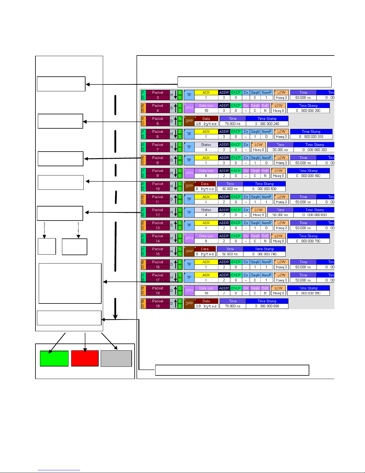
The following picture presents the interaction between the application and a running verification script:
Page 10 of 107
Page 11
LeCroy Corporation Verification Script Engine Reference Manual
S
F
V
erification Sc ript
A pplicatio n
(Run verification script)
OnStartScript()
Call..
tarting VSE running …
ProcessEvent()
ProcessEvent()
ProcessEvent()
ProcessEvent()
Data…
File
ProcessEvent()
Set out.Re su lt =
_VERIFICATION_PASSED
or
_VERIFICATION_FAILED
will comp le t e the scr ipt run.
COM
Client
Call..
(If expected event )
Call..
(If expected event )
Call..
(If expected event )
Call..
(If expected event )
Call..
(If expected
event )
OnFinishScript()
PASSED
FAILED
Call..
DONE
erification Script results
Note: Verification script result <DONE> means that the script is intended for extracting and displaying some
information from recorded traces only, and you do not care about results. To specify that your script is for
displaying information only, call the function ScriptForDisplayOnly() somewhere in your script (in
OnStartScript(), for instance).
inishing VSE running … …
Page 11 of 107
Page 12
LeCroy Corporation Verification Script Engine Reference Manual
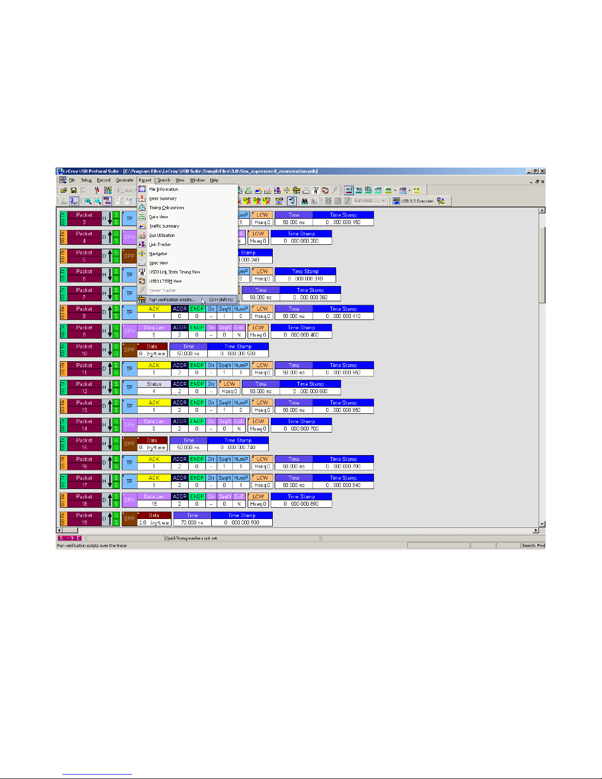
4 Running Verification Scripts from Application
To run a verification script over a trace, you select the main menu item Report > Run verification scripts or
click the Run verification scripts button on the main tool bar (if it is not hidden):
Page 12 of 107
Page 13
LeCroy Corporation Verification Script Engine Reference Manual
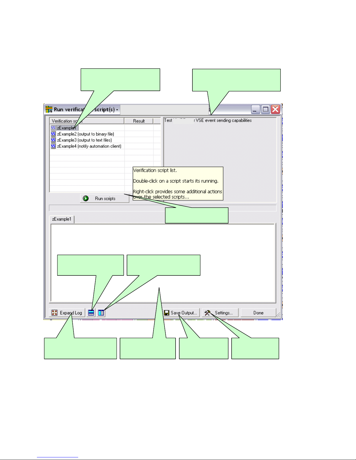
V
The Run verification scripts dialog opens where you choose then run one or several verification scripts:
erification Script List.
Name for scripts are file names
without extension.
Verification Script description.
Descriptions for scripts are defined in
set DecoderDesc= "MyDescription";
Finds a view related to the
verified trace and place this
window under it.
Expands output windows. (
Shortcut key : F11. Shift+F11
also maximizes dialog. )
Starts running selected
verif ica tio n scrip ts
Finds a view related to the
verified trace and place this
window by the right side of it.
Tabbed output
windows for selected
verification script s.
Saves contents of
ou tput window s in
text files.
Allows to set
different settings.
Page 13 of 107
Page 14
LeCroy Corporation Verification Script Engine Reference Manual
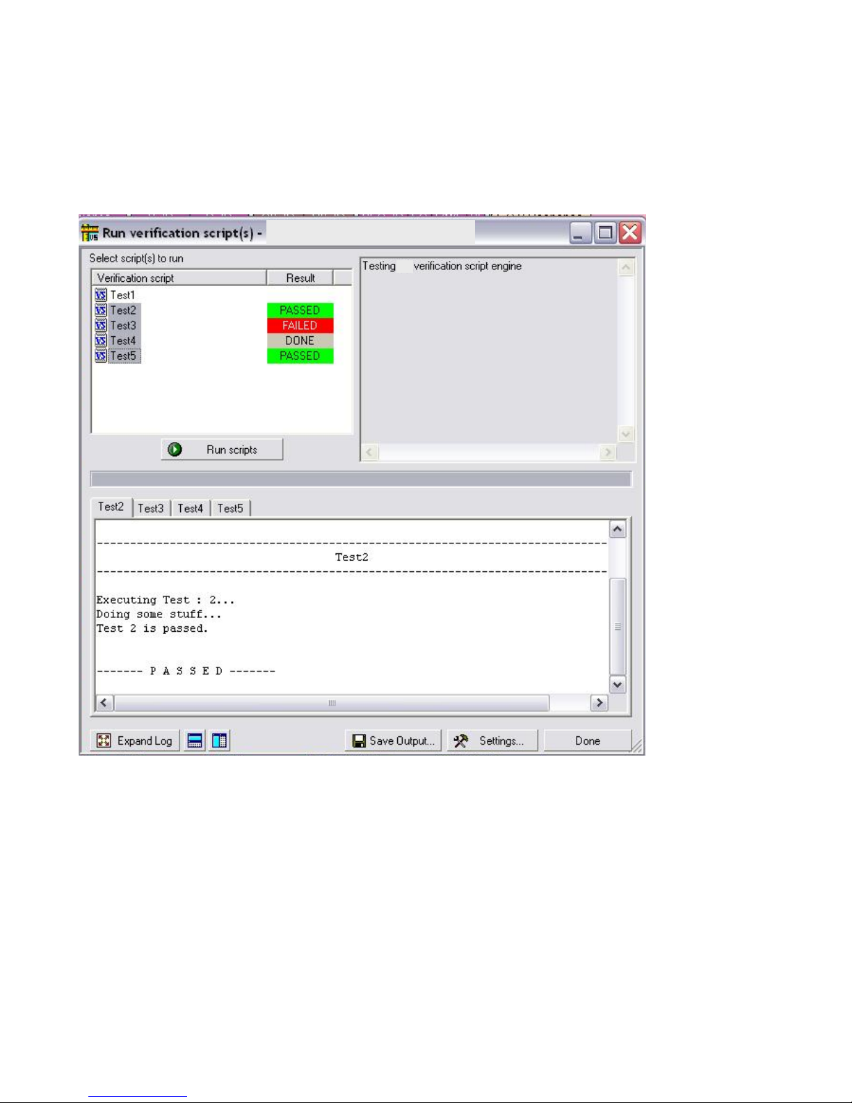
4.1 Running Verification Scripts
Push the button Run scripts after you select scripts to run. VSE starts running the selected verification scripts,
shows script report information in the output windows, and presents the results of verifications in the script list:
Page 14 of 107
Page 15
LeCroy Corporation Verification Script Engine Reference Manual
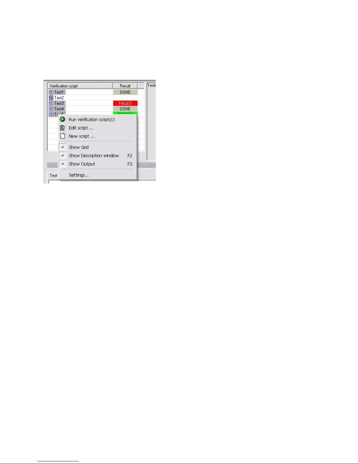
Right-clicking the script list displays some additional operations over selected scripts:
Run verification script(s):
Edit script: Edit selected scripts in the editor application specified in Editor settings.
New script: Create a new script file using the template specified in Editor settings.
Show Grid
Show Description window
Show Output
Settings: Open a special Setting dialog to specify different settings for VSE.
: Show/hide a grid in the verification script list.
: Show/hide the script output windows (Shortcut key F3).
Start running selected script(s).
: Show/hide the script description window (Shortcut key F2).
Page 15 of 107
Page 16
LeCroy Corporation Verification Script Engine Reference Manual
p
g
p
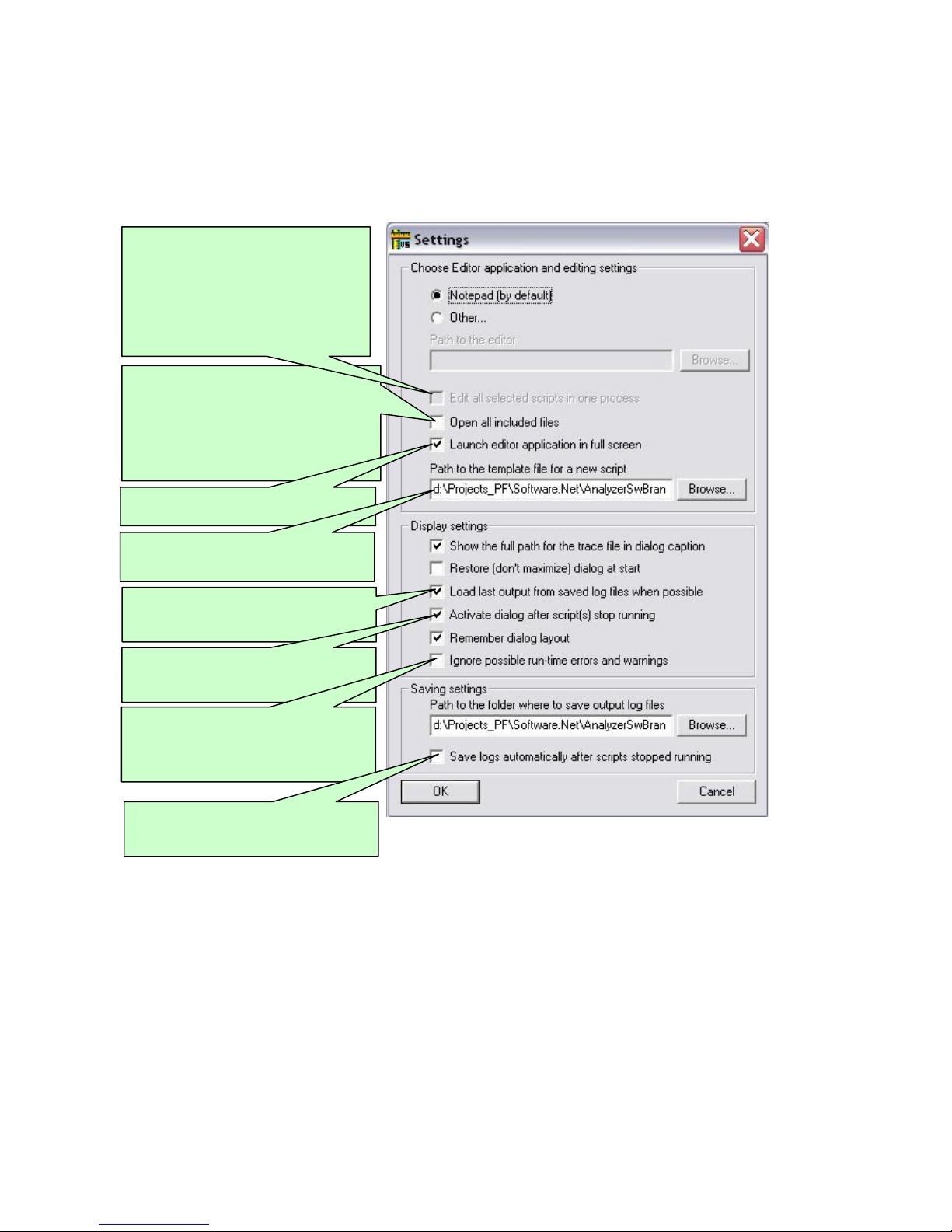
4.2 VSE GUI Settings
After choosing Settings, the following dialog appears:
This option (if set) allows editor
applications supporting multi-document
interface (MDI) to edit a ll s cr ip t files
related to the selected scripts in one
application instance.
Otherwise, a new application instance
will be launched for each script file.
This option (if set) allows editor
applications to edit all included files
(extension : *.inc) along with main
verification script files (extension : *.vs e )
Otherwise, only main verification script
files will be opened for editing.
Launches editor application in full screen
mode.
Full path to the file to be used as a
template for a new script.
This setting (if set) specifies that the last
saved output for selected scripts should
be loaded into the out
This setting (if set) brings Run VS dialog
to foreground when scripts stopped
runnin
.
This option specifies that potential runtime errors and warnings like calling not
defined functions etc. shouldn't be
reported.
This setting (if set) forces the application
to save output automatically when the
scri
ts stopped running.
ut windows.
See screen pop-up tooltips for
explanation of other settings…
Page 16 of 107
Page 17

LeCroy Corporation Verification Script Engine Reference Manual
5 Verification Script Engine Input Context Members
All verification scripts have input contexts, special structures that can be used inside of the scripts. The
application fills their members. The verification script input contexts have two sets of members:
• Trace event-independent set of members
• Trace event-dependent set of members
Note: All input context members have integer type values unless their types are explicitly specified.
If possible values for input context members are not explicitly specified, they should comply with the current USB
specifications.
5.1 Trace Event-independent Set of Members
This set of members is defined and can be used for any event passed to a script:
in.Level: Transaction level of the trace event. It can be one of the following constants:
_PKT: Packet level (value = 0)
_TRA: Transaction level (value = 1)
_SPL_TRA: Split Transaction level (value = 2)
_XFER: Transfer level (value = 3)
in.Index: Index of the event in the trace file (packet number for packets etc).
in.Time: Time of the event (type = list, having format = 2 sec 125 ns -> [2 , 125]. For more information, see
section 10.1 VSE Time Object
In.Channel: Indicates on which channel the event occured. It can be one of the following constants:
_USB2: USB2 traffic (value = 1)
_USB3_RX: USB3 Host Receive traffic (Upstream, value = 2)
_USB3_TX: USB3 Host Transmit traffic (Downstream, value = 3)
in.Speed: Indicates the speed for the trace event. It can be one of the following constants:
_FS: USB2 Full Speed (value = 1)
_LS: USB2 Low Speed (value = 2)
_HS: USB2 High Speed (value = 3)
_SS: USB3 Super Speed (value = 4)
in.Direction: Indicates the direction for the trace event. It can be one of the following constants:
_IN: Direction is from Host to Device (value = 2)
_OUT: Direction is from Device to Host (value = 3)
_BOTH: Trace event involves traffic in both directions (value = 4)
in.TraceEvent: Type of trace events. (Application predefined constants are used. See list of possible events
in Chapter 7. Verification Script Engine Events
in.Notification: Type of notifications. (Application predefined constants are used. Currently no notifications
are defined.)
.
.)
Page 17 of 107
Page 18

LeCroy Corporation Verification Script Engine Reference Manual
5.2 Trace Event-dependent Set of Members
This set of members is defined and can be used only for a specific event or after calling functions that provide
values of variables:
5.2.1 USB Packet-specific Set of Members
Members of this set are valid for all USB packet events:
in.RawPacket: Bit source of the whole packet. (You can extract any necessary information using the
GetNBits(), NextNBits(), or PeekNBits() functions.
In.RawPacketLength: Length of the packet (in bytes).
In.Duration: Time it took to transmit the packet on the bus (VSE Time object
In.Errors: A bitmap of packet level errors. The table below describes the current list of possible packet errors
and their bit positions in the error bitmap:
Error type Bit position Description
USB2 Errors:
PID_ERROR 1 Bad PID value
CRC5_ERROR 2 Bad CRC5
CRC16_ERROR 3 Bad CRC16
PACKETLEN_ERROR 4 Wrong packet length
BIT_STUFF_ERROR 5 Bit stuffing error
EOP_ERROR 6 Bad End Of Packet
BABBLE_START_ERROR 7 Babble start error
BABBLE_END_ERROR 8 Babble end (Loss Of Activity) error
FRAME_LENGTH_ERROR 9 Wrong frame length
HANDSHAKE_TIMEOUT_ERROR 10 Bad turnaroud timing or timeout
condition for handshake
INTERNAL_ERROR 11 Analyzer internal error
DATA_TOGGLE_ERROR 12 Data toggling error
MICROFRAME_ERROR 13 Bad frame or microframe number
MOD_8_ERROR 14 Last Byte Incomplete error
OTG_ERROR 15 Bad OTG Signal value
USB3 Errors. TBD.
).
Page 18 of 107
Page 19

LeCroy Corporation Verification Script Engine Reference Manual
5.2.1.1 USB Bus Condition-specific Set of Members
Note: Valid for Bus Condition trace events only, undefined for other events.
In.BusCondition: Type of Bus Condition events.
The table below describes the current list of possible Bus Condition events and values of in.BusCondition:
Bus Condition in.BusCondition Value Description
CHIRP_K _CHIRP_K 0 Device “K” Chirp to notify host
of Hi Speed capability
CHIRP_J _CHIRP_J 1 Device “J” Chirp to notify host
of Hi Speed capability
FS_K_ON_HS _FS_K_ON_HS 2 Full Speed “K” signaling on Hi
Speed branch
FS_J_ON_HS _FS_J_ON_HS 3 Full Speed “J” signaling on Hi
Speed branch
SUSPEND _SUSPEND 4 Suspend signaling
RESUME _RESUME 5 Resume signaling
SE1 _SE1 6 SE1 signaling
SE0 _SE0 7 SE0 FS or LS signaling (can
be keep-alive for LS)
VBUS_VOLTAGE_CHANGE _VBUS_VOLTAGE_CHANGE 44(0x2C) Change of Vbus Voltage
in.BusConditionDuration: Duration of the Bus Condition event in nanoseconds.
Page 19 of 107
Page 20

LeCroy Corporation Verification Script Engine Reference Manual
5.2.1.2 USB2 Packet-specific Set of Members
Note: Valid for USB2 packets only, undefined for other events.
The following input context members apply to most of the USB2 packets.
In.Pid: Packet Identifier value for the packet. It is the full PID value, the following constants are defined in the
VS_constants.inc include file and can be used by scripts:
# USB 2.0 PID values
const PID_OUT = 0x87;
const PID_IN = 0x96;
const PID_SOF = 0xA5;
const PID_SETUP = 0xB4;
const PID_DATA0 = 0xC3;
const PID_DATA1 = 0xD2;
const PID_DATA2 = 0xE1;
const PID_MDATA = 0xF0;
const PID_ACK = 0x4B;
const PID_NAK = 0x5A;
const PID_STALL = 0x78;
const PID_NYET = 0x69;
const PID_PRE = 0x3C;
const PID_ERR = 0x3C;
const PID_SPLIT = 0x1E;
const PID_PING = 0x2D;
const PID_EXT = 0x0F;
in.SubPidPacket: If non-zero, signals that this packet is a protocol extension token as defined by the Link
Power Management ECN. In this case the Pid value should be treated as the SubPid (only LPM currently
defined).
In.CRC5: CRC5 value for packets (not relevant for Data packets).
Page 20 of 107
Page 21

LeCroy Corporation Verification Script Engine Reference Manual
5.2.1.2.1 USB2 Token Packet Members
in.Addr: Value of the Address (ADDR) field of the Token packet.
In.Endp: Value of the Endpoint (ENDP) field of the Token packet.
5.2.1.2.2 USB2 Start Of Frame Packet Members
in.FrmNum: Frame number for the current USB2 frame.
In.MicroFrmNum: Microframe number for the current microframe as determined by the Analyzer (would be
zero for Full Speed frames).
5.2.1.2.3 USB2 Data Packet Members
in.Payload: Bit source of the packet payload. (You can extract any necessary information using GetNBits(),
NextNBits(), or PeekNBits() function.
In.PayloadLength: Length (in bytes) of the packet payload.
In.CRC16: CRC16 value for the Data packet.
5.2.1.2.4 USB2 Split Token Packet Members
in.HubAddr: Value of the Hub Address field, the USB device address of the hub supporting the specified full-
/low-speed device for this full-/low-speed transaction.
In.SC: Value of the Start/Complete bit for the split token.
In.Port: Value of the Port field – the port number of the target hub for which this full-/low-speed transaction is
destined.
In.S: Value of the Speed bit for the split token.
In.E: Value of the End bit for the split token.
In.ET: Value of the Endpoint Type field for the split token.
Page 21 of 107
Page 22

LeCroy Corporation Verification Script Engine Reference Manual
5.2.1.2.5 Link Power Management Extended Token Members
in.HIRD: Value of the Host Initiated Resume Duration field.
In.bLinkState: Value of the bLinkState field for the LPM extended token.
In.bRemoteWake: Value of the bRemoteWake bit for the LPM extended token.
In.Reserved: Value of the reserved field for the LPM extended token.
Page 22 of 107
Page 23

LeCroy Corporation Verification Script Engine Reference Manual
5.2.1.3 USB3 Packet-specific Set of Members
Note 1: Valid for USB3 packets only, undefined for other events.
Note 2: The system does not pass all possible fields of USB3 packets as members of Input Context. If a script
needs to use the values of those fields, use the GetHexPktField
5.2.1.3.12
for examples.
5.2.1.3.1 TSEQ Training Sequence Ordered Set Members
in.Count: Value of TSEQ count, the number of sequential TSEQ sequences sent
5.2.1.3.2 TS1/TS2 Training Sequence Ordered Set Members
in.Count: Value of TS count, the number of sequential TS1 or TS2 sequences sent
in.LnkFunctionality: Value of the whole Link Functionality (Link Configuration) byte in the training
sequence
in.Reset: Value of the Reset bit in the Link Configuration byte.
In.SSDisable: Value of the Spread Spectrum bit in the Link Configuration byte.
In.Loopback: Value of the Loopback asserted/deasserted bit in the Link Configuration byte.
In.ScrDisable: Value of the Disable Scrambling bit in the Link Configuration byte.
and GetDecodedPktField functions. See
5.2.1.3.3 LFPS Packet Members
in.Type: Type of LFP signaling
in.Duration: Duration of LFP signaling in nanoseconds
5.2.1.3.4 Inter-Packet Symbols Packet Members
in.NumOfSymbols: Number of symbols in the IPS sequence
5.2.1.3.5 Link Command Packet Members
in.LnkCmd: Value of Link Command information for the Link command
Page 23 of 107
Page 24

LeCroy Corporation Verification Script Engine Reference Manual
5.2.1.3.6 SKIP Packet Members
in.Count: Count of symbols in the SKIP sequence
5.2.1.3.7 Logical Idle Packet Members
in.Count: Count of symbols in the Logical Idle sequence
5.2.1.3.8 Link Management Packet Members
in.SubType: SubType value for LMP. Use constant definitions in VS_constants.inc.
5.2.1.3.9 Isochronous Timestamp Packet Members
in.BusICounter: Bus Interval Counter value for ITP, in 1/8 of a millisecond
in.Delta: Time Delta value for ITP
in.BusIAdjCtrl: Bus Interval Adjustment Control value for ITP, specifying the device in control of
bus interval adjustment
5.2.1.3.10 Transaction Packet Members
in.SubType: SubType value for Transaction Packet. Use constant definitions in VS_constants.inc.
in.Addr: Address of the device that receives this Transaction Packet
in.Endp: Endpoint number on the device that receives this Transaction Packet
in.Dir: Direction for the specified Endpoint
in.StreamID: Value of the StreamID field
Page 24 of 107
Page 25

LeCroy Corporation Verification Script Engine Reference Manual
5.2.1.3.11 Data Packet Members
in.Addr: Address of the device which is the recipient of this Data Packet
in.Endp: Endpoint number on the device which is the recipient of this Data Packet
in.Dir: Direction for the specified Endpoint
in.StreamID: Value of the StreamID field
in.SeqN: Value of the Sequence Number for this Data Packett
in.DataLength: Length of the payload for this Data Packet
in.PayloadLength: Length of the payload actually recorded for this Data Packet
in.Payload: Bit source of the packet payload for this Data Packet. (You can extract any necessary
information using the GetNBits(), NextNBits(), or PeekNBits() function.)
in.CRC32: Value of CRC32 protecting the payload for this Data Packet
Note: In USB Protocol Suite software versions earlier than 3.71 (namely, 3.60 and 3.70), Data Packet Header
and Data Packet Payload were two separate packet types with input context members split accordingly between
them. Those were combined into a single Data Packet starting with version 3.71.
Page 25 of 107
Page 26

LeCroy Corporation Verification Script Engine Reference Manual
5.2.1.3.12 Getting Values of the Fields not present in Input Context
As mentioned earlier, not all the possible fields of USB3 packets are passed as members of Input Context. The
following are examples of using GetHexPktField
not present in Input Context.
If( in.TraceEvent == _USB3_LMP_PKT )
{
# Example of using decoded packet information for LMPs.
# ‘SubType’ field,
# String value
str = FormatEx(“\tSubType(str) = ‘%s’”, GetDecodedPktField(“SubType”));
ReportText( str );
# Hex Value
val = GetHexPktField ( “SubType” );
str = FormatEx( “\tSubType(hex) = 0x%X\n”, val );
ReportText( str );
# ‘Hseq’ field
# String value
str = FormatEx( “\tHseq(str) = ‘%s’”, GetDecodedPktField ( “Hseq” ) );
ReportText( str );
# Hex Value
val = GetHexPktField ( “Hseq” );
str = FormatEx( “\tHseq(hex) = 0x%X\n”, val );
ReportText( str );
}
if( ( in.TraceEvent == _USB3_TP_PKT ) && ( in.SubType == TP_ACK ) )
{
# Example of using decoded packet information for TPs.
# ‘SeqN’ field
# String value
str = FormatEx( “\tSeqN(str) = ‘%s’”, GetDecodedPktField ( “SeqN” ) );
ReportText( str );
# Hex Value
val = GetHexPktField ( “SeqN” );
str = FormatEx( “\tSeqN(hex) = 0x%X\n”, val );
ReportText( str );
# ‘NumP’ field
# String value
str = FormatEx( “\tNumP(str) = ‘%s’”, GetDecodedPktField ( “NumP” ) );
ReportText( str );
and GetDecodedPktField functions to get values of the fields
Page 26 of 107
Page 27

LeCroy Corporation Verification Script Engine Reference Manual
# Hex Value
val = GetHexPktField ( “NumP” );
str = FormatEx( “\tNumP(hex) = 0x%X\n”, val );
ReportText( str );
}
if( in.TraceEvent == _USB3_DP_PKT )
{
# Example of using decoded packet information for DPs.
# ‘SeqN’ field
# String value
str = FormatEx( “\tSeqN(str) = ‘%s’”, GetDecodedPktField ( “SeqN” ) );
ReportText( str );
# Hex Value
val = GetHexPktField ( “SeqN” );
str = FormatEx( “\tSeqN(hex) = 0x%X\n”, val );
ReportText( str );
# ‘ENDP’ field
# String value
str = FormatEx( “\tENDP(str) = ‘%s’”, GetDecodedPktField ( “ENDP” ) );
ReportText( str );
# Hex Value
val = GetHexPktField ( “ENDP” );
str = FormatEx( “\tENDP(hex) = 0x%X\n”, val );
ReportText( str );
}
# Link Control Word
if( ( in.TraceEvent == _USB3_TP_PKT ) ||
( in.TraceEvent == _USB3_DP_PKT ) )
{
ReportText( “LCW:” );
val = GetHexPktField ( “Hseq” );
str = FormatEx( “\tHseq = %d”, val );
ReportText( str );
val = GetHexPktField ( “Hdepth” );
str = FormatEx( “\tHDepth = %d”, val );
ReportText( str );
val = GetHexPktField ( “D1” );
str = FormatEx( “\tDelayed (D1) = %d”, val );
ReportText( str );
val = GetHexPktField ( “D2” );
str = FormatEx( “\tDeferred (D2) = %d\n”, val );
ReportText( str );
}
Page 27 of 107
Page 28

LeCroy Corporation Verification Script Engine Reference Manual
5.2.2 Transaction-specific Set of Members
in.TraToken: Token PID for the transaction. Possible values are:
const PID_OUT = 0x87;
const PID_IN = 0x96;
const PID_SETUP = 0xB4;
const PID_SPLIT = 0x1E;
const PID_PING = 0x2D;
const PID_EXT = 0x0F;
in.Addr: Device Address value for this Usb transaction.
In.Endp: Device Endpoint Number value for this Usb transaction.
In.TraCompletionFlag: Handshake PID for the transaction (if any). Possible values are:
const PID_ACK = 0x4B;
const PID_NAK = 0x5A;
const PID_STALL = 0x78;
const PID_NYET = 0x69;
const PID_ERR = 0x3C;
0xFFFFFFFF – in case no handshake was sent for the transaction.
In.Complete: Flag, signaling if the transaction was complete.
In.XferType: Type of the USB Transfer this transaction belongs to. See Transfer Types for possible values.
In.CtrlDirection: For a Setup transaction represents the direction of the corresponding Control Transfer.
0 = Host-to-device
1 = Device-to-host
in.FirstInXfer: This flag is set when the transaction is first in the transfer it belongs to.
In.LastInXfer: This flag is set when the transaction is last in the transfer it belongs to.
In.Errors: Error code for the transaction, if any error happened.
If the transaction is a Setup transaction, the following input context members provide values of the
corresponding fields of the USB Device Request:
in.ReqType
in.ReqRecipient
in.bRequest
in.wIndex
in.wValue
in.wLength
Page 28 of 107
Page 29

LeCroy Corporation Verification Script Engine Reference Manual
in.Split: Signals that the transaction is a start-split or complete-split.
In.HubAddr: Value of the Hub Address field, the USB device address of the hub supporting the specified full-
/low-speed device for this full-/low-speed transaction.
In.SC: Value of the Start/Complete bit for the split token.
In.Port: Value of the Port field – the port number of the target hub for which this full-/low-speed transaction is
destined.
In.S: Value of the Speed bit for the split token.
In.E: Value of the End bit for the split token.
In.ET: Value of the Endpoint Type field for the split token.
In.OTGHostId: For USB On-The-Go transactions, indicates if the A-device is acting as the host (value of 0) or
the B-device is acting as the host (value of 1).
In.OTGErrorCode: For USB On-The-Go transactions, indicates error code if non-zero.
In.OTGErrorCodeOffset: For USB On-The-Go transactions with errors, indicates the offset from the first
packet in the transaction to the packet with error.
In.PayloadLength: Length (in bytes) of the packet payload. If zero, the transaction does not have any
payload.
In.Payload: Bit source of the transaction data payload. Note: You can extract any necessary information using
the GetNBits(), NextNBits(), or PeekNBits() function.
Page 29 of 107
Page 30

LeCroy Corporation Verification Script Engine Reference Manual
5.2.3 Split Transaction-specific Set of Members
All the input context members that are defined for USB2 transactions are also applicable to Split Transactions. In
addition to those, Split Transactions define the following members:
in.TraHalted: Indicates that this split transaction was halted.
Page 30 of 107
Page 31

LeCroy Corporation Verification Script Engine Reference Manual
5.2.4 Transfer-specific Set of Members
in.XferType: Type of transfer. Repeats the trace event value for the transfer.
In.Addr: Device Address value for this USB transfer.
In.Endp: Device Endpoint Number value for this USB transfer.
In.Completed: Flag signaling if the transfer was completed.
In.Halted: Flag signaling if the transfer was halted (usually that means STALL handshake sent).
In.CtrlDirection: For a Control Transfer, represents the direction:
0 = Host-to-device
1 = Device-to-host
If the transfer is a Control Transfer, the following input context members provide values of the corresponding
fields of the USB Device Request:
in.ReqType
in.ReqRecipient
in.bRequest
in.wIndex
in.wValue
in.wLength
in.ClassicOnHigh: When set, indicates that this transfer was a classic speed transfer that was executed and
captured on a high speed branch (upstream from a high speed hub).
In.OTGHostId: For USB On-The-Go transfers, indicates if the A-device is acting as the host (value of 0) or the
B-device is acting as the host (value of 1).
In.PayloadLength: Length (in bytes) of the transfer payload. If zero, transfer does not have any payload.
Care should be taken not to request payload for the transfers that moved large amounts of data.
In.Payload: Bit source of the transfer payload. Note: You can extract any necessary information using the
GetNBits(), NextNBits(), or PeekNBits() function.
Note: Refer to the section Script decoded fields retrieving functions
decoded values at the Transfer level.
for information about getting the script
Page 31 of 107
Page 32

LeCroy Corporation Verification Script Engine Reference Manual
6 Verification Script Engine Output Context Members
All verification scripts have output contexts, special structures that can be used inside of the application. The
scripts fill their members. The verification script output contexts have only one member:
out.Result: Result of the whole verification program defined in the verification script.
This member can have three values:
• _VERIFICATION_PROGRESS: Set by default when a script starts running.
• _VERIFICATION_PASSED
• _VERIFICATION_FAILED
The last two values should be set if you decide that a recorded trace does (or does not) satisfy the imposed
verification conditions. In both cases, the verification script stops running.
If you do not specify any of those values, the result of script execution is set to VERIFICATION_FAILED at exit.
Note: If you do not care about the result of script running, call the function ScriptForDisplayOnly
stopping the script. The result is DONE.
once before
Page 32 of 107
Page 33

LeCroy Corporation Verification Script Engine Reference Manual
7 Verification Script Engine Events
VSE defines a large group of trace “events” that can be passed to a verification script for evaluating, retrieving,
and displaying some contained information. The information about the type of event can be seen in the
in.TraceEvent input context member.
The application defines a set of VSE constants for Trace Event types. Those constants should be used by the
scripts for determining the event types.
See the topic “Sending Functions” for details about how to specify the events to send to verification scripts.
Page 33 of 107
Page 34

LeCroy Corporation Verification Script Engine Reference Manual
7.1 Packet Level Events
The table below describes the current list of packet level (lowest level of transactions) events and values
(application-defined constants) for in.TraceEvent:
Types of packets in.TraceEvent
USB2 packet events
All USB2 packet events _USB2_PACKET
USB2 Bus conditions _USB2_BUS_CONDITION
USB2 Start Of Frame packets _USB2_SOF
USB2 Token packets _USB2_TOKEN
USB2 Data packets _USB2_DATA
USB2 Handshake packet _USB2_HSK
USB2 SPLIT packets _USB2_SPLIT
USB Full Speed Hub prefix packets _USB2_PRE
USB2 Link Power Management extended token _USB2_LPM
All other USB2 packets _USB2_OTHER
USB3 packet events
All USB3 packet events _USB3_PACKET
TSEQ Training Sequence Ordered Sets _USB3_TSEQ
TS1 Training Sequence Ordered Sets _USB3_TS1
TS2 Training Sequence Ordered Sets _USB3_TS2
Low Frequency Periodic Signaling _USB3_LFPS
Interpacket Symbols _USB3_IPS
Link Commands _USB3_LINK_CMD
SKIP Sequences _USB3_SKP_SEQ
Logical Idle Symbols _USB3_SYMBOL_IDLE
Isochronous Timestamp packets _USB3_ITP_PKT
Link Management packets _USB3_LMP_PKT
Transaction packets _USB3_TP_PKT
Data Packets _USB3_DP_PKT
Data Packet headers _USB3_DPH_PKT (only for traces before
Data payload packets _USB3_DPP_PKT (only for traces before
All other USB3 packets _USB3_OTHER_PKT
software version 3.71)
software version 3.71)
Page 34 of 107
Page 35

LeCroy Corporation Verification Script Engine Reference Manual
7.2 Transaction Level Events
The table below describes the current list of transaction level events and values (application-defined constants)
for in.TraceEvent:
Types of transactions in.TraceEvent
Setup transactions _T_SETUP
In transactions _T_IN
Out transactions _T_OUT
All other transaction types _T_OTHER
7.3 Split Transaction Level Events
The table below describes the current list of split transaction level events and values (application-defined
constants) for in.TraceEvent:
Types of transactions in.TraceEvent
All split transactions _SPLIT_TRA
7.4 Transfer Level Events
The table below describes the current list of transfer level events and values (application-defined constants) for
in.TraceEvent:
Types of transfers in.TraceEvent
Control transfers _X_CONTROL
Isochronous transfers _X_ISO
Bulk transfers _X_BULK
Interrupt transfers _X_INTERRUPT
All other (undefined) transfer types _X_OTHER
Page 35 of 107
Page 36

LeCroy Corporation Verification Script Engine Reference Manual
8 Sending Functions
This topic contains information about the special group of VSE functions that specify the events the
verification script should expect to receive.
8.1 SendLevel()
This function specifies that events of specified transaction level should be sent to the script.
Currently only frame level events can be sent to verification scripts.
Format: SendLevel(level)
Parameters:
level Can be one of following values:
_PKT: Packet level (value = 0)
_TRA: Transaction level (value = 1)
_SPL_TRA: Split Transaction level (value = 2)
_XFER: Transfer level (value = 3)
Remark:
If no level was specified, events of frame level are sent to the script by default.
Example:
…
SendLevel(_PKT); # Send packet level events.
Page 36 of 107
Page 37

LeCroy Corporation Verification Script Engine Reference Manual
8.2 SendLevelOnly()
This function specifies that ONLY events of a specified transaction level should be sent to the script.
Currently only frame level events can be sent to verification scripts.
Format: SendLevelOnly(level)
Parameters:
level Can be one of following values:
_PKT: Packet level (value = 0)
_TRA: Transaction level (value = 1)
_SPL_TRA: Split Transaction level (value = 2)
_XFER: Transfer level (value = 3)
Example:
…
SendLevelOnly(_PKT); # Send ONLY packet level events.
Page 37 of 107
Page 38

LeCroy Corporation Verification Script Engine Reference Manual
8.3 DontSendLevel()
This function specifies that events of a specified transaction level should NOT be sent to the script.
Currently only frame level events can be sent to verification scripts.
Format: DontSendLevel(level)
Parameters:
level Can be one of following values:
_PKT: Packet level (value = 0)
_TRA: Transaction level (value = 1)
_SPL_TRA: Split Transaction level (value = 2)
_XFER: Transfer level (value = 3)
Example:
…
DontSendLevel(_SPL_TRA); # DO NOT send split transaction level events.
Page 38 of 107
Page 39

LeCroy Corporation Verification Script Engine Reference Manual
8.4 SendChannel()
This function specifies that events on the specified channel should be sent to the script.
Format: SendChannel(channel)
Parameters:
channel Can be one of following values:
_USB2: USB2 traffic (value = 1)
_USB3_RX: USB3 Host Receive traffic (Upstream, value = 2)
_USB3_TX: USB3 Host Transmit traffic (Downstream, value = 3)
Example:
SendChannel(_USB2); # Send events from USB2 channel.
…
SendChannel(_CHANNEL_2); # Send events from channel 2 (USB3_RX).
SendChannel(_CHANNEL_3); # Send events from channel 3 (USB3_TX).
…
SendChannel(2); # Send events from channel 2 (USB3_RX).
SendChannel(3); # Send events from channel 3 (USB3_TX).
…
Page 39 of 107
Page 40

LeCroy Corporation Verification Script Engine Reference Manual
8.5 SendChannelOnly()
This function specifies that ONLY events occuring on a specified channel should be sent to the script.
Format: SendChannelOnly(channel)
Parameters:
channel Can be one of following values:
_USB2: USB2 traffic (value = 1)
_USB3_RX: USB3 Host Receive traffic (Upstream, value = 2)
_USB3_TX: USB3 Host Transmit traffic (Downstream, value = 3)
Example:
SendChannelOnly (_USB2); # Send ONLY events from USB2 channel.
…
SendChannelOnly (_CHANNEL_2); # Send ONLY events from channel 2(USB3_RX).
SendChannelOnly (_CHANNEL_3); # Send ONLY events from channel 3(USB3_TX).
…
SendChannelOnly (2); # Send ONLY events from channel 2 (USB3_RX).
SendChannel Only (3); # Send ONLY events from channel 3 (USB3_TX).
…
Page 40 of 107
Page 41

LeCroy Corporation Verification Script Engine Reference Manual
8.6 DontSendChannel()
This function specifies that events occuring on a specified channel should NOT be sent to the script.
Format: DontSendChannel (channel)
Parameters:
channel Can be one of following values:
_USB2: USB2 traffic (value = 1)
_USB3_RX: USB3 Host Receive traffic (Upstream, value = 2)
_USB3_TX: USB3 Host Transmit traffic (Downstream, value = 3)
Example:
DontSendChannel(_USB3_TX); # DO NOT send events from USB3 downstream channel.
…
DontSendChannel(_CHANNEL_2); # DO NOT send events from channel 2 (USB3_RX).
DontSendChannel(_CHANNEL_3); # DO NOT send events from channel 3 (USB3_TX).
…
DontSendChannel(2); # DO NOT send events from channel 2 (USB3_RX).
DontSendChannel(3); # DO NOT send events from channel 3 (USB3_TX).
…
Page 41 of 107
Page 42

LeCroy Corporation Verification Script Engine Reference Manual
8.7 SendAllChannels()
This function specifies that events occuring on ALL channels should be sent to the script.
Format: SendAllChannels ()
Example:
…
SendAllChannels (); # Send events from ALL channels.
Page 42 of 107
Page 43

LeCroy Corporation Verification Script Engine Reference Manual
8.8 SendTraceEvent()
This function specifies the events to be sent to a script.
Format: SendTraceEvent(event)
Parameters:
event Can have one of the Trace Event values defined in
Chapter 7 “Verification Script Engine Events
Example:
…
SendTraceEvent(_USB2_TOKEN); # Send USB2 Token packet trace events.
SendTraceEvent(_USB2_BUS_CONDITION); # Send bus condition trace events.
…
SendTraceEvent(_T_SETUP) # Send Setup Transactions.
”
Page 43 of 107
Page 44

LeCroy Corporation Verification Script Engine Reference Manual
8.9 DontSendTraceEvent()
This function specifies that the event specified in this function should not be sent to a script.
Format: DontSendTraceEvent (event)
Parameters:
event See SendTraceEvent()
Example:
…
SendTraceEvent(_PACKET); # Send all packets.
…
if(SomeCondition)
{
DontSendTraceEvent (_USB2_SOF); # Don’t send Start Of Frame packets.
DontSendTraceEvent (_USB2_SPLIT); # Don’t send Split tokens.
}
for all possible values.
Page 44 of 107
Page 45

LeCroy Corporation Verification Script Engine Reference Manual
8.10 SendTraceEventOnly()
This function specifies that ONLY the event specified in this function is sent to the script.
Format: SendTraceEventOnly(event)
Parameters:
event See SendTraceEvent()
Remark:
This function may be useful, when there are many events to be sent, to send only one kind of event and not
send the other ones.
Example:
…
SendTraceEvent(_PACKET); # Send all packets.
…
if(SomeCondition)
{
SendTraceEventOnly (_USB2_TOKEN);
# Only Token packets are sent.
}
for all possible values
Page 45 of 107
Page 46

LeCroy Corporation Verification Script Engine Reference Manual
8.11 SendAllTraceEvents()
This function specifies that ALL trace events relevant for the selected transaction level are sent to the
script.
Format: SendAllTraceEvents ()
Example:
…
SendAllTraceEvents (); # Send all types of trace events.
Page 46 of 107
Page 47

LeCroy Corporation Verification Script Engine Reference Manual
8.12 SendDirection()
This function specifies more precise tuning for sending events only for a specified direction of the link.
Format: SendDirection (direction)
Parameters:
direction Can have one of the following values:
Primitive Values
Constant Direction
_IN
_OUT
_ANY
If this parameter parameter is omitted, trace events of all directions are sent, which is the same as:
SendTraceEvent(_ANY);
Example:
SendBusState(_IN); # Send events that were transmitted from Host to Device.
SendBusState(); # Send events in all directions.
SendBusState(_ANY); # Send events in all directions.
Direction is from Host to Device (value = 2)
Direction is from Device to Host (value = 3)
Any Direction
Page 47 of 107
Page 48

LeCroy Corporation Verification Script Engine Reference Manual
8.13 SendUsb2BusConditions()
This function specifies more precise tuning for USB2 Bus Condition events. Only selected bus co ndition
events are sent.
Format: SendUsb2BusConditions (condition)
Parameters:
condition Specifies bus condition.
This parameter can have one of the following values:
BusCondition Constant Value Description
_CHIRP_K 0 Device “K” Chirp to notify host
of Hi Speed capability
_CHIRP_J 1 Device “J” Chirp to notify host
of Hi Speed capability
_FS_K_ON_HS 2 Full Speed “K” signaling on
Hi Speed branch
_FS_J_ON_HS 3 Full Speed “J” signaling on
Hi Speed branch
_SUSPEND 4 Suspend signaling
_RESUME 5 Resume signaling
_SE1 6 SE1 signaling
_SE0 7 SE0 FS or LS signaling
(can be keep-alive for LS)
_VBUS_VOLTAGE_CHANGE 44(0x2C) Change of Vbus Voltage
_ANY All bus condition events
Example:
# Send only Resume signaling events.
SendUsb2BusConditions(_RESUME);
…
# Send all bus condition events.
SendUsb2BusConditions (_ANY);
# or
SendUsb2BusConditions ();
Page 48 of 107
Page 49

LeCroy Corporation Verification Script Engine Reference Manual
8.14 SendUsb2TokenPackets()
This function specifies more precise tuning for USB2 Token packets.
Format: SendUsb2TokenPackets (pid, address, endpoint)
Parameters:
pid Specifies that only Token packets with the specified PID value are sent.
The value _ANY means any PID is accepted.
The possible PID values are
const PID_OUT = 0x87;
const PID_IN = 0x96;
const PID_SETUP = 0xB4;
const PID_SPLIT = 0x1E;
const PID_PING = 0x2D;
const PID_EXT = 0x0F;
address Specifies that only Token packets with the specified Address value are sent.
The value _ANY means any Address is accepted.
endpoint Specifies that only Token packets with the specified Endpoint value are sent.
The value _ANY means any Endpoint is accepted.
Example:
# Send any Token packet.
SendUsb2TokenPackets();
# Send all SETUP packets.
SendUsb2TokenPackets (PID_SETUP);
# Send all IN tokens for address 5 endpoint 1.
SendUsb2TokenPackets (PID_IN, 3);
# Send all OUT tokens for address 3.
SendUsb2TokenPackets (PID_OUT, 5, 1);
# Send all token packets for endpoint zero.
SendUsb2TokenPackets (_ANY, _ANY, 0);
Page 49 of 107
Page 50

LeCroy Corporation Verification Script Engine Reference Manual
8.15 SendUsb2DataPackets ()
This function specifies more precise tuning for Data packets.
Format: SendUsb2DataPackets(pid)
Parameters:
pid Specifies that only Data packets with the specified data PID are sent.
The value _ANY means any data packet is accepted.
The follofwing PID values apply:
const PID_DATA0 = 0xC3;
const PID_DATA1 = 0xD2;
const PID_DATA2 = 0xE1;
const PID_MDATA = 0xF0;
Example:
# Send any Data packet.
SendUsb2DataPackets();
# Send only MDATA packets.
SendUsb2DataPackets(PID_MDATA);
Page 50 of 107
Page 51

LeCroy Corporation Verification Script Engine Reference Manual
8.16 SendUsb2HskPackets()
This function specifies more precise tuning for Handshake packets.
Format: SendUsb2HskPackets(pid)
Parameters:
pid Specifies that only Data packets with the specified data PID are sent.
The value _ANY means any data packet is accepted.
The follofwing PID values apply:
const PID_ACK = 0x4B;
const PID_NAK = 0x5A;
const PID_STALL = 0x78;
const PID_NYET = 0x69;
const PID_ERR = 0x3C;
Example:
# Send any handshake.
SendUsb2HskPackets();
# Send only STALL handshakes.
SendUsb2HskPackets (PID_STALL);
Page 51 of 107
Page 52

LeCroy Corporation Verification Script Engine Reference Manual
8.17 SendTransaction()
This function works on the Transaction level and allows specifying more precise tuning for the
transaction events that are sent to the script.
Format: SendTransaction(tra_type, xfer_type, address, endpoint, completion_flag,
only_with_errors)
Parameters:
tra_type Specifies the type of Transaction event (see transaction event types
xfer_type Specifies the type of Transfer this transaction is being part of (see transfer event types
address Specifies that only Transaction events with the specified Address value are sent.
The value _ANY means any Address is accepted.
endpoint Specifies that only Transaction events with the specified Endpoint value are sent.
The value _ANY means any Endpoint is accepted.
completion_flag Specifie s that only Transaction events with the specified Handshake PIDs are sent.
The value _ANY means any handshake is accepted.
The possible values are:
const PID_ACK = 0x4B;
const PID_NAK = 0x5A;
const PID_STALL = 0x78;
const PID_NYET = 0x69;
const PID_ERR = 0x3C;
only_with_errors When set to one, specifies that only Transaction events with errors at the transaction
level are sent.
Example:
# Send SETUP transactions for any Transfer type and address 0.
SendTransaction( _T_SETUP, _ANY, 0 );
# Send OUT transactions for any transfer type, address 1, endpoint 0.
SendTransaction( _T_OUT, _ANY, 1, 0 );
# Send IN transactions for BULK transfers that were acknoledged by ACK.
SendTransaction( _T_IN, _X_BULK, _ANY, _ANY, PID_ACK );
# Send IN transactions with errors.
SendTransaction( _T_IN, _ANY, _ANY, _ANY, _ANY, 1 );
).
).
Page 52 of 107
Page 53

LeCroy Corporation Verification Script Engine Reference Manual
8.18 SendTransfer()
This function works on the Transfer level and allows specifying more precise tuning for the transfer
events that are sent to the script.
Format: SendTransfer(xfer_type, address, endpoint, completed, only_with_errors)
Parameters:
xfer_type Specifies the type of Transfer to send to the script (see transfer event types
The value _ANY means any transfer type is accepted.
address Specifies that only Transfer events with the specified Address value are sent.
The value _ANY means any Address is accepted.
endpoint Specifies that only Transfer events with the specified Endpoint value are sent.
The value _ANY means any Endpoint is accepted.
completed Specifies that only Transfers that are complete (1, default) or incomplete (0) should be
sent to the script.
only_with_errors When set to one, specifies that only Transfer events with errors at the transfer level are
sent.
Example:
# Send Control Transfers for address 0.
SendTransfer( _X_CONTROL, 0 );
# Send BULK transfers with errors.
SendTransfer( _X_BULK, _ANY, _ANY, 0, 1 );
).
Page 53 of 107
Page 54

LeCroy Corporation Verification Script Engine Reference Manual
8.19 SendPktsWithBadCRC()
This function instructs VSE to send packets with bad CRC to the script. By default, packets with bad
CRC are not sent to verification scripts.
• To determine whether a packet has an CRC5 or CRC16 error, check in.Errors
(It is different from 0 if there are some header errors. See the in.Errors section for full error bit
descriptions.)
Format : SendPktsWithBadCRC( send_packets_with_bad_crc )
Parameters:
send_packets_with_bad_crcr
Example:
SendAllChannels (); # Send events from ALL channels.
SendAllTaceEvents(); # Send all events.
SendPktsWithBadCRC(); # Send packets with CRC errors.
…
crc16_error_mask = 0x8; # Bit 3 (if set) indicates CRC16 error.
if( in.Errors & crc16_error_mask)
{
# Handle CRC16 error.
}
…
SendPktsWithBadCRC ( 0 ); # Send frames with no CRC errors.
Optional parameter specifies whether frames with bad CRC should be
sent to the verification script or not.
If it is omitted or set to 1, frames with bad CRC are sent to the script.
Otherwise, VSE sends only frames with correct CRC.
Page 54 of 107
Page 55

LeCroy Corporation Verification Script Engine Reference Manual
9 Packet and Script Decoded Fields Retrieving Functions
This group of functions covers VSE generic capability to extract information about data payload fields decoded
with CATC Script Language (CSL) at Transfer level and all decoded fields at Packet level for USB3 packets.
9.1 GetDecodedPktField()
Extracts information about a USB3 packet field and determines how it is shown in the USB Protocol Suite
trace view or the "View … Fields" dialog.
Format : GetDecodedPktField ( fld_name )
Parameters
fld_name Name of the field supposedly existing in the current packet
Return Values
If the field name is in the current packet, the return value is the text value of the decoded field and how to display
it in the trace view. Otherwise, the return value is the empty string.
Example
if( in.TraceEvent == _USB3_LMP_PKT )
{
# Example of using decoded packet information for LMPs.
# ‘SubType’ field
# String value
str = FormatEx(“\tSubType(str) = ‘%s’”, GetDecodedPktField(“SubType”));
ReportText( str );
}
Remark
The field name should be exactly the same as it is in the trace. The field name is case sensitive.
Page 55 of 107
Page 56

LeCroy Corporation Verification Script Engine Reference Manual
9.2 GetHexPktField()
Extracts the raw hexadecimal value of the USB3 packet field.
Format : GetHexPktField ( fld_name )
Parameters
fld_name Name of the field supposedly existing in the current packet
Return Values
If the field name is in the current packet, the function returns the hex value of the decoded field:
o integer value if field length is less than 32 bits
o raw binary value if field length is greater than 32 bits. The raw binary value gives a list of bytes.
See the CSL Manual for further details about raw binary values.
o null value if the field was not found.
Example
# Link Control Word
if( ( in.TraceEvent == _USB3_TP_PKT ) ||
( in.TraceEvent == _USB3_DP_PKT ) )
{
ReportText( “LCW:” );
val = GetHexPktField ( “Hseq” );
str = FormatEx( “\tHseq = %d”, val );
ReportText( str );
val = GetHexPktField ( “Hdepth” );
str = FormatEx( “\tHDepth = %d”, val );
ReportText( str );
val = GetHexPktField ( “D1” );
str = FormatEx( “\tDelayed (D1) = %d”, val );
ReportText( str );
val = GetHexPktField ( “D2” );
str = FormatEx( “\tDeferred (D2) = %d\n”, val );
ReportText( str );
}
Remark
The field name should be exactly the same as it is in the trace. The field name is case sensitive.
Page 56 of 107
Page 57

LeCroy Corporation Verification Script Engine Reference Manual
9.3 GetDecodedScriptField()
Extracts information about the script decoded field and determines how it is shown in the USB Protocol Suite
trace view or the “View … Fields” dialog.
Format : GetDecodedScriptField ( fld_name )
Parameters:
fld_name Name of the field supposedly existing in the current Transfer
Return Values:
If the field name is in the current Transfer, the return value is the text value of the decoded field and how to
display it in the trace. Otherwise, the return value is the empty string.
Example:
# Extract the decoded value of wValue field
# for a Control transfer that uses a certain Class
# or Vendor specific decoding.
str = GetDecodedScriptField (“wValue”);
# If the bulk transfer payload decoded by the script decoder
# has a field named 'Code' (i.e., PTP transfers):
str = FormatEx( " Code(str) = '%s' ", GetDecodedScriptField ( "Code" ) );
Remarks:
The field name should be exactly the same as it is in the trace. The field name is case sensitive.
This function can be used only at the Transfer level.
Page 57 of 107
Page 58

LeCroy Corporation Verification Script Engine Reference Manual
9.4 GetHexScriptField()
Extracts the raw hexadecimal value of the script decoded field.
Format : GetHexScriptField ( fld_name )
Parameters
fld_name Name of the field supposedly existing in the current Transfer
Return Values
If the field name is in the current Transfer, the function returns the hex value of the decoded field:
o integer value if field length is less than 32 bits
o raw binary value if field length is greater than 32 bits. The raw binary value gives a list of bytes.
See the CSL Manual for further details about raw binary values.
o null value if the field was not found.
Example
# Extract the hex value of the LBA field for mass storage.
val = GetHexScriptField ( “Logical Block Addr” );
# Extract the hex value of the SomeBig field.
if( GetHexScriptField ( "Some Big" ) == 'FE80000000000000' )
ReportText( "Some Big field = FE80-0000-0000-0000");
Remarks
The field name should be exactly the same as it is in the trace. The field name is case sensitive.
This function can be used only at the Transfer level.
Page 58 of 107
Page 59

LeCroy Corporation Verification Script Engine Reference Manual
10 Timer Functions
This group of functions covers VSE capability to work with timers, internal routines that repeatedly measure a
timing interval between different events.
10.1 VSE Time Object
A VSE time object presents time intervals in verification scripts. The verification script time object is a
“list” object of two elements.
[seconds, nanoseconds]
Note: The best way to construct a VSE time object is to use the Time() function (see below).
Page 59 of 107
Page 60

LeCroy Corporation Verification Script Engine Reference Manual
10.2 SetTimer()
Starts a timing calculation from the event at which this function was called.
Format: SendTimer(timer_id = 0)
Parameters:
timer_id Unique timer identifier.
Example:
SetTimer(); # Start timing for timer with id = 0.
SetTimer(23); # Start timing for timer with id = 23.
Remark:
If this function is called a second time for the same timer ID, it resets the timer and starts timing the calculation
again from the point where it was called.
Page 60 of 107
Page 61

LeCroy Corporation Verification Script Engine Reference Manual
10.3 KillTimer()
Stops a timing calculation for a specific timer and frees related resources.
Format: KillTimer(timer_id = 0)
Parameters:
timer_id Unique timer identifier.
Example:
KillTimer(); # Stop timing for timer with id = 0.
KillTimer(23); # Stop timing for timer with id = 23.
Page 61 of 107
Page 62

LeCroy Corporation Verification Script Engine Reference Manual
10.4 GetTimerTime()
Retrieves a timing interval from the specific timer.
Format: GetTimerTime (timer_id = 0)
Parameters:
timer_id Unique timer identifier.
Return values:
Returns a VSE time object from a timer with id = timer_id.
Example:
GetTimerTime (); # Retrieve timing interval for timer with id = 0.
GetTimerTime (23); # Retrieve timing interval for timer with id = 23.
Remark:
This function, when called, does not reset the timer.
Page 62 of 107
Page 63

LeCroy Corporation Verification Script Engine Reference Manual
11 Time Construction Functions
This group of functions is used to construct VSE time objects.
11.1 Time()
Constructs a verification script time object.
Format: Time(nanoseconds)
Time(seconds, nanoseconds)
Parameters:
nanoseconds Number of nanoseconds in specified time
neconds Number of seconds in specified time
Return values:
First function returns [0, nanoseconds], second one returns [seconds, nanoseconds]
Example:
Time (50 * 1000); # Create time object of 50 microseconds.
Time (3, 100); # Create time object of 3 seconds and 100 nanoseconds.
Time(3 * MICRO_SECS); # Create time object of 3 microseconds.
Time(4 * MILLI_SECS); # Create time object of 4 milliseconds.
Note: MICRO_SECS and MILLI_SECS are constants defined in VS_constants.inc.
Page 63 of 107
Page 64

LeCroy Corporation Verification Script Engine Reference Manual
12 Time Calculation Functions
This group of functions covers VSE capability to work with “time”, the VSE time objects.
12.1 AddTime()
Adds two VSE time objects.
Format: AddTime(time1, time2)
Parameters:
time_1 VSE time object representing the first time interval
time_2 VSE time object representing the second time interval
Return values:
Returns a VSE time object representing a time interval equal to sum of time_1 and time_2
Example:
t1 = Time(100);
t2 = Time(2, 200);
t3 = AddTime(t1, t2) # Returns VSE time object = 2 sec 300 ns.
Page 64 of 107
Page 65

LeCroy Corporation Verification Script Engine Reference Manual
12.2 SubtractTime()
Subtracts two VSE time objects.
Format: SubtractTime (time1, time2)
Parameters:
time_1 VSE time object presenting first time interval
time_2 VSE time object presenting second time interval
Return values:
Returns a VSE time object representing a time interval equal to subtraction of time_1 and time_2
Example:
t1 = Time(100);
t2 = Time(2, 200);
t3 = SubtractTime (t2, t1) # Returns VSE time object = 2 sec 100 ns.
Page 65 of 107
Page 66

LeCroy Corporation Verification Script Engine Reference Manual
12.3 MulTimeByInt()
Multiplies a VSE time object by an integer value.
Format: MulTimeByInt (time, mult)
Parameters:
time VSE time object
mult Multiplier, integer value
Return values:
Returns a VSE time object representing a time interval equal to time * mult
Example:
t = Time(2, 200);
t1 = MulTimeByInt (t, 2) # Returns VSE time object = 4 sec 400 ns.
Page 66 of 107
Page 67

LeCroy Corporation Verification Script Engine Reference Manual
12.4 DivTimeByInt()
Divides a VSE time object by an integer value.
Format: DivTimeByInt (time, div)
Parameters:
time VSE time object
div Divider, integer value
Return values:
Returns a VSE time object representing time interval equal to time / div.
Example:
t = Time(2, 200);
t1 = DivTimeByInt (t, 2) # Returns VSE time object = 1 sec 100 ns.
Page 67 of 107
Page 68

LeCroy Corporation Verification Script Engine Reference Manual
13 Time Logical Functions
This group of functions covers VSE capability to compare VSE time objects.
13.1 IsEqualTime()
Verifies that one VSE time object is equal to another VSE time object.
Format: IsEqualTime (time1, time2)
Parameters:
time_1 VSE time object representing the first time interval
time_2 VSE time object representing the second time interval
Return values:
Returns 1 if time_1 is equal to time_2,
Returns 0 otherwise.
Example:
t1 = Time(100); t2 = Time(500);
If(IsEqualTime(t1, t2)) DoSomething();
Page 68 of 107
Page 69

LeCroy Corporation Verification Script Engine Reference Manual
13.2 IsLessTime()
Verifies that one VSE time object is less than another VSE time object.
Format: IsLessTime (time1, time2)
Parameters:
time_1 VSE time object representing the first time interval
time_2 VSE time object representing the second time interval
Return values:
Returns 1 if time_1 is less than time_2,
Returns 0 otherwise.
Example:
t1 = Time(100); t2 = Time(500);
If(IsLessTime (t1, t2)) DoSomething();
Page 69 of 107
Page 70

LeCroy Corporation Verification Script Engine Reference Manual
13.3 IsGreaterTime()
Verifies that one VSE time object is greater than another VSE time object.
Format: IsGreaterTime (time1, time2)
Parameters:
time_1 VSE time object representing the first time interval
time_2 VSE time object representing the second time interval
Return values:
Returns 1 if time_1 is greater than time_2,
Returns 0 otherwise.
Example:
t1 = Time(100); t2 = Time(500);
If(IsGreaterTime (t1, t2)) DoSomething();
Page 70 of 107
Page 71

LeCroy Corporation Verification Script Engine Reference Manual
13.4 IsTimeInInterval()
Verifies that a VSE time object is greater than a minimum VSE time object and less than a maximum
VSE time object.
Format: IsTimeInInterval(min_time, time, max_time)
Parameters:
min_time VSE time object representing a minimum interval
time VSE time object representing a time interval
max_time VSE time object representing a maximum interval
Return values:
Returns 1 if min_time <= time <= max_time,
Returns 0 otherwise.
Example:
t1 = Time(100);
t = Time(400);
t2 = Time(500);
If(IsTimeInInterval (t1, t, t2)) DoSomething();
Page 71 of 107
Page 72

LeCroy Corporation Verification Script Engine Reference Manual
14 Time Text Functions
This group of functions covers VSE capability to convert VSE time objects into text strings.
14.1 TimeToText()
Converts a VSE time object into text.
Format: TimeToText (time)
Parameters:
time VSE time object
Return values:
Returns a text representation of a VSE time object.
Example:
t = Time(100);
ReportText(TimeToText(t)); # See below details for ReportText() function.
Page 72 of 107
Page 73

LeCroy Corporation Verification Script Engine Reference Manual
15 Output Functions
This group of functions covers VSE capability to present information in the output window.
15.1 ReportText()
Outputs text in the output window related to the verification script.
Format: ReportText (text)
Parameters:
text Text variable, constant or literal
Example:
…
ReportText (“Some text”);
…
t = “Some text”
ReportText (t);
…
num_of_packets = in.NumOfPackets;
text = Format(“Number of frames = %d”, num_of_packets);
ReportText (text);
…
x = 0xAAAA;
y = 0xBBBB;
text = FormatEx(“x = 0x%04X, y = 0x%04X”, x, y);
ReportText(“Text = ” + text);
…
Page 73 of 107
Page 74

LeCroy Corporation Verification Script Engine Reference Manual
15.2 EnableOutput()
Enables showing information in the output window and sending COM reporting notifications to COM
clients.
Format: EnableOutput ()
Example:
EnableOutput ();
Page 74 of 107
Page 75

LeCroy Corporation Verification Script Engine Reference Manual
15.3 DisableOutput()
Disables showing information in the output window and sending COM reporting notifications to COM
clients.
Format: DisableOutput ()
Example:
DisableOutput ();
Page 75 of 107
Page 76

LeCroy Corporation Verification Script Engine Reference Manual
16 Information Functions
16.1 GetTraceName()
This function returns the filename of the trace file being processed by VSE.
Format: GetTraceName(filepath_compatible)
Parameters:
filepath_compatible If this parameter is present and not equal to 0, the returned value
may be used as part of the filename.
Example:
ReportText(“Trace name = ” + GetTraceName());
…
File = OpenFile("C:\\My Files\\" + GetTraceName(1) + "_log.log");
# For trace file with path "D:\Some Traces\Data.usb"
# GetTraceName(1) returns "D_Some Traces_Data.usb"
Page 76 of 107
Page 77

LeCroy Corporation Verification Script Engine Reference Manual
16.2 GetScriptName()
This function returns the name of the verification script where this function is called.
Format: GetScriptName()
Example:
ReportText(“Current script = ” + GetScriptName());
Page 77 of 107
Page 78

LeCroy Corporation Verification Script Engine Reference Manual
16.3 GetApplicationFolder()
This function returns the full path to the folder where the application was started.
Format: GetApplicationFolder()
Example:
ReportText(“Application folder = ” + GetApplicationFolder ());
Page 78 of 107
Page 79

LeCroy Corporation Verification Script Engine Reference Manual
16.4 GetCurrentTime()
This function returns the string representation of the current system time.
Format: GetCurrentTime()
Example:
# Yields current time in format “May 18, 2006, 5:49 PM”
ReportText(GetCurrentTime());
Page 79 of 107
Page 80

LeCroy Corporation Verification Script Engine Reference Manual
17 Navigation Functions
17.1 GotoEvent()
This function forces the application to jump to some trace event and shows it in the main trace view.
Format: GotoEvent(level, index)
GotoEvent()
Parameters:
level Transaction level of the event to jump
index Transaction index of the event to jump
Remarks:
If no parameters were specified, the application jumps to the current event being processed by VSE.
If wrong parameters were specified (for example, index exceeding the maximal index for the specified
transaction level), the function does nothing and an error message is sent to the output window.
Example:
…
if(Something == interesting) GotoEvent(); # Go to the current event.
…
if(SomeCondition)
{
interesting_level = in.Level;
interesting_index = in.Index;
}
…
OnFinishScript()
{
…
# Go to the interesting event.
GotoEvent(interesting_level, interesting_index);
}
Page 80 of 107
Page 81

LeCroy Corporation Verification Script Engine Reference Manual
17.2 SetMarker()
This function sets a marker for some trace event.
Format: SetMarker(marker_text)
SetMarker(marker_text, level, index)
Parameters:
marker_text Text of the marker
level Transaction level of the event to jump
index Transaction index of the event to jump
Remarks:
If no parameters were specified, other than marker_text, the application sets the marker to the current event
being processed by VSE.
If wrong parameters were specified (for example, index exceeding the maximal index for the specified
transaction level), the function does nothing and an error message is sent to the output window.
Example:
…
# Set marker to the current event.
if(Something == interesting) SetMarker("!!! Something cool !!!");
…
if(SomeCondition)
{
interesting_level = in.Level;
interesting_index = in.Index;
}
…
OnFinishScript()
{
…
# Set marker to the interesting event.
SetMarker(" !!! Cool Marker !!! ", interesting_level, interesting_index);
# Go to the interesting event.
GotoEvent(interesting_level, interesting_index);
}
Page 81 of 107
Page 82

LeCroy Corporation Verification Script Engine Reference Manual
18 File Functions
This group of functions covers VSE capabilities to work with external files.
Page 82 of 107
Page 83

LeCroy Corporation Verification Script Engine Reference Manual
18.1 OpenFile()
This function opens a file for writing.
Format: OpenFile(file_path, append, mode)
Parameters:
file_path Full path to the file to open. (For ‘\’ use ‘\\’)
append This parameter (if present and not equal to 0) specifies that VSE should append
the following write operations to the contents of the file; otherwise, the
contents of the file are cleared.
mode This parameter specifies the open mode (text or binary) for the file.
If omitted, text mode is used. It can be one of the following values:
_FO_BINARY (= 0): Opens file in binary mode
_FO_TEXT (= 1): Opens file in text mode (by default)
Return Values:
The “handle” to the file to be used in other file functions.
Example:
…
set file_handle = 0;
…
file_handle = OpenFile(“D:\\Log.txt”); # Opens file in text mode.
# The previous contents
# are erased.
…
WriteString(file_handle, “Some Text1”); # Write text string to file.
WriteString(file_handle, “Some Text2”); # Write text string to file.
…
CloseFile(file_handle); # Closes the file.
…
# Opens file in text mode.
# The following file operations append to the contents of the file.
file_handle = OpenFile(GetApplicationFolder() + “Log.txt”, _APPEND);
# Opens file in binary mode. The previous contents are erased.
file_handle = OpenFile(“D:\\data.bin”, 0, _FO_BINARY);
…
Write(file_handle, 0xAABBCCDD); # Writes integer value into the binary file.
CloseFile(file_handle); # Closes the binary file.
Page 83 of 107
Page 84

LeCroy Corporation Verification Script Engine Reference Manual
18.2 CloseFile()
This function closes an opened file.
Format: CloseFile(file_handle)
Parameters:
file_handle File “handle”
Example:
…
set file_handle = 0;
…
file_handle = OpenFile(“D:\\Log.txt”); # Opens file.
# The previous contents are erased.
…
WriteString(file_handle, “Some Text1”); # Write text string to file.
WriteString(file_handle, “Some Text2”); # Write text string to file.
…
CloseFile(file_handle); # Closes file.
…
Page 84 of 107
Page 85

LeCroy Corporation Verification Script Engine Reference Manual
18.3 WriteString()
This function writes a text string to the file.
Format: WriteString(file_handle, text_string)
Parameters:
file_handle File “handle”
text_string Text string
Remarks:
If the file_handle parameter refers to a text file, then a trailing End-Of-Line symbol is added to the text. In case
of binary files, the End-Of-Line symbol is not added.
Example:
…
set file_handle = 0;
…
file_handle = OpenFile(“D:\\Log.txt”); # Opens text file.
# The previous contents are erased.
…
WriteString(file_handle, “Some Text1”); # Write text string to file.
WriteString(file_handle, “Some Text2”); # Write text string to file.
…
CloseFile(file_handle); # Close the file.
…
Page 85 of 107
Page 86

LeCroy Corporation Verification Script Engine Reference Manual
18.4 Write()
This function writes data to the file.
Format: Write(file_handle, value, num_of_bytes)
Parameters:
file_handle "handle" to the file previously opened by OpenFile()
value Data to write
num_of_bytes Optional parameter specifying how many bytes to take from the
value parameter (if omitted, length is calculated automatically
based on the value type)
Remarks:
This function is primarily for binary files. It can be used for text files only if the value parameter is a string of text.
In that case, it is equivalent to the WriteString() function and the num_of_bytes parameter is ignored.
Example:
…
set BinFile = 0;
…
BinFile = OpenFile("C:\\data.bin", 0, _FO_BINARY);
…
# Write a string to the binary file.
Write(BinFile, "All we need is love!!!");
# Write a substring ("All") to the binary file.
Write(BinFile, "All we need is love!!!", 3);
val = 0xBEEF;
Write(BinFile, val); # Writes integer = (EF BE 00 00) to the binary file.
Write(BinFile, val, 2); # Writes WORD = (EF BE) to the binary file.
# Write a byte chain to the binary file.
Write(BinFile, 'AABBCCDDEEFF12345678');
# Write a list of values to the binary file.
Write(BinFile, [ 0xAA, "USB", 12, 0xBEEF ]);
…
CloseFile(BinFile); # Closes the binary file.
…
Page 86 of 107
Page 87

LeCroy Corporation Verification Script Engine Reference Manual
18.5 ShowInBrowser()
This function opens a file in the Windows Explorer. If the extension of the file has the application
registered to open files with such extensions, it is launched. For instance, if Internet Explorer is
registered to open files with extension .htm and the file handle passed to ShowInBrowser() function
belongs to a file with such an extension, then this file is opened in the Internet Explorer.
Format: ShowInBrowser (file_handle)
Parameters:
file_handle File “handle”
Example:
…
set html_file = 0;
…
html_file = OpenFile(“D:\\Log.htm”);
…
WriteString(html_file, “<html><head><title>LOG</title></head>”);
WriteString(html_file, “<body>”);
…
WriteString(html_file, “</body></html>”);
ShowInBrowser(html_file); # Opens the file in Internet Explorer.
CloseFile(html_file);
…
Page 87 of 107
Page 88

LeCroy Corporation Verification Script Engine Reference Manual
19 Trace File Exporting Functions
This group of functions covers VSE capabilities to export data into trace files.
Page 88 of 107
Page 89

LeCroy Corporation Verification Script Engine Reference Manual
19.1 CreateTraceFile()
This function creates a trace file.
Format: CreateTraceFile( file_path )
Parameters:
file_path Full path to the trace file to be created. (For
Return Values:
The “handle” to the trace file to be used in other trace-file-related functions.
Remarks:
If file_path contains just a file name (such as test.usb), the trace file is created in the application folder.
Example:
…
set trace_handle = 0;
…
# Create a trace file in "C:\\data_output.usb".
trace_handle = CreateTraceFile(“C:\\data_output.usb”);
…
# Add the current trace event (frame) to the trace file.
AddEventToTraceFile(trace_handle);
…
CloseTraceFile(trace_handle); # Close the file.
…
‘\’ use ‘\\’)
Page 89 of 107
Page 90

LeCroy Corporation Verification Script Engine Reference Manual
19.2 CloseTraceFile()
This function closes an open trace file. All attempts to add trace data to a closed trace file are ignored.
Format: CloseTraceFile( tracefile_handle )
Parameters:
tracefile_handle Trace File “handle” returned by the CreateTraceFile() function.
Example:
…
set trace_handle = 0;
…
# Create a trace file in "C:\\data_output.usb".
trace_handle = CreateTraceFile(“C:\\data_output.usb”);
…
# Add the current trace event (frame) to the trace file.
AddEventToTraceFile(trace_handle);
…
CloseTraceFile(trace_handle); # Close the file.
…
Page 90 of 107
Page 91

LeCroy Corporation Verification Script Engine Reference Manual
19.3 AddEventToTraceFile()
This function adds the current trace event (such as frames) to the trace file.
Format: AddEventToTraceFile ( tracefile_handle )
Parameters:
tracefile_handle
Remarks:
If this function is called multiple times for the same event, only the first call adds an event to the trace file. All the
other calls are ignored.
Example:
…
set trace_handle = 0;
…
# Create a trace file in "C:\\data_output.usb".
trace_handle = CreateTraceFile(“C:\\data_output.usb”);
…
# Add the current trace event (frame) to the trace file.
AddEventToTraceFile(trace_handle);
…
CloseTraceFile(trace_handle); # Close the file.
…
Trace File “handle” returned by the CreateTraceFile() function.
Page 91 of 107
Page 92

LeCroy Corporation Verification Script Engine Reference Manual
19.4 OpenTraceFile()
This function opens a trace file in the application.
Format: OpenTraceFile (tracefile_path)
Parameters:
tracefile_path Path to a trace file to open.
Remarks:
If tracefile_path contains just a file name (such as test.usb), VSE looks for a trace file with such a name in the
application folder.
Example:
…
set trace_handle = 0;
…
# Create a trace file in "C:\\data_output.usb".
trace_handle = CreateTraceFile(“C:\\data_output.usb”);
…
# Add the current trace event (frame) to the trace file.
AddEventToTraceFile(trace_handle);
…
CloseTraceFile(trace_handle); # Close the trace file.
…
# Instruct the application to open the trace file "C:\\data_output.usb".
OpenTraceFile("C:\\data_output.usb");
Page 92 of 107
Page 93

LeCroy Corporation Verification Script Engine Reference Manual
20 COM/Automation Communication Functions
This group of functions covers VSE capabilities to communicate with COM/Automation™ clients connected to
the application. (See the Automation Manual for details about how to connect to the application and VSE.)
20.1 NotifyClient()
This function sends information to COM/Automation™ client applications in custom format. The client
application receives a VARIANT object, which it is supposed to parse.
Format: NotifyClient(event_id, param_list)
Parameters:
event_id Integer parameter representing event identifier
param_list List of parameters to be sent to the client application.
Each parameter might be an integer, string, raw data (byte chain), or list.
Because the list itself may contain integers, strings, raw data, or other lists, it is possible
to send very complicated messages. (Lists should be treated as arrays of VARIANTs.)
Example:
...
if(SomeCondition())
{
NotifyClient(2, [ in.Index, "USB2 CHANNEL", “USB2 packet”, in.Pid,
in. PayloadLength, TimeToText(in.Time)]);
}
...
# Send two parameters to client applications:
# 2 (integer),
# [ in.Index, "USB2 CHANNEL", “USB2 packet”, in.Pid,
# in. PayloadLength, TimeToText(in.Time)] (list)
Remark:
See an example of handling this notification by client applications and parsing code in the Automation Manual.
Page 93 of 107
Page 94

LeCroy Corporation Verification Script Engine Reference Manual
21 User Input Functions
21.1 MsgBox()
Displays a message in a dialog box, waits for the user to click a button, and returns an Integer indicating
which button the user clicked.
Format: MsgBox(prompt, type, title)
Parameters:
prompt Required. String expression displayed as the message in the dialog box.
type Optional. Numeric expression that is the sum of values specifying the number
and type of buttons to display, the icon style to use, the identity of the default button,
and the modality of the message box. If omitted, the default value for buttons is
_MB_OK. (See the list of possible values in the table below.)
title Optional. String expression displayed in the title bar of the dialog box.
If title is omited, the script name is placed in the title bar.
The type argument values are:
Constant Description
_MB_OKONLY Display OK button only (by Default).
_MB_OKCANCEL Display OK and Cancel buttons.
_MB_RETRYCANCEL Display Retry and Cancel buttons.
_MB_YESNO Display Yes and No buttons.
_MB_YESNOCANCEL Display Yes, No, and Cancel buttons.
_MB_ABORTRETRYIGNORE Display Abort, Retry, and Ignore buttons.
_MB_EXCLAMATION Display Warning Message icon.
_MB_INFORMATION Display Information Message icon.
_MB_QUESTION Display Warning Query icon.
_MB_STOP Display Critical Message icon.
_MB_DEFBUTTON1 First button is default.
_MB_DEFBUTTON2 Second button is default.
_MB_DEFBUTTON3 Third button is default.
_MB_DEFBUTTON4 Fourth button is default.
Page 94 of 107
Page 95

LeCroy Corporation Verification Script Engine Reference Manual
Return Values:
This function returns an integer value indicating which button was clicked.
Constant Description
_MB_OK OK button was clicked.
_MB_CANCEL Cancel button was clicked.
_MB_YES Yes button was clicked.
_MB_NO No button wa s clicked.
_MB_RETRY Retry button was clicked.
_MB_IGNORE Ignore button was clicked.
_MB_ABORT Abort button was clicked.
Remark:
This function works only for VS Engines controlled via a GUI. For VSEs controlled by COM/Automation™ clients,
it does nothing.
This function "locks" the application, which means that there is no access to other application features until the
dialog box is closed. To prevent too many MsgBox calls (in case a script is not written correctly), VSE keeps
track of all function calls demanding user interaction and doesn't show dialog boxes if some customizable limit is
exceeded (returns _MB_OK in this case).
Example:
…
if(Something)
{
…
str = "Something happened!!!\nShould we continue?"
result = MsgBox(str ,
_MB_YESNOCANCEL | _MB_EXCLAMATION,
"Some Title");
if(result != _MB_YES)
ScriptDone();
# Go on…
}
Page 95 of 107
Page 96

LeCroy Corporation Verification Script Engine Reference Manual
21.2 InputBox()
Displays a prompt in a dialog box, waits for the user to input text or click a button, and returns a CSL list
object or string containing the contents of the text box.
Format: InputBox(prompt, title, default_text, return_type)
Parameters:
prompt Required. String expression displayed as the message in the dialog box.
title Optional. String expression displayed in the title bar of the dialog box.
If title is omitted, the script name is placed in the title bar.
default_text Optional. String expression displayed in the text box as the default response
if no other input is provided. If default_text is omited, the text box is displayed empty.
return_type Optional. It specifies the contents of the return obje ct.
The return_type argument values are:
Constant Value Description
_IB_LIST 0
_IB_STRING 1 String input as it was typed in the text box
Return Values:
Depending on the return_type argument, this function returns either a CSL list object or the text typed in the text
box as it is.
If return_type = _IB_LIST (by default), the text in the text box is considered to be a set of list items divided by ','
(only hexadecimal, decimal and string items are currently supported).
For example, the text:
Hello world !!!, 12, Something, 0xAA, 10, "1221"
produces a CSL list object (5 items):
list = [ "Hello world !!!", 12, "Something", 0xAA, 10, "1221" ];
list [0] = "Hello world !!!"
list [1] = 12
list [2] = "Something"
list [3] = 0xAA
list [4] = 10
list [5] = "1212"
CSL list object is returned (by Default).
Page 96 of 107
Page 97

LeCroy Corporation Verification Script Engine Reference Manual
Note: Although the dialog box input text parser tries to determine a type of list item automatically, text enclosed
in quote signs " " is always considered to be a string.
Remark:
This function works only for VS Engines controlled via a GUI. For VSEs controlled by COM/Automation™ clients,
it does nothing.
This function "locks" the application, which means that there is no access to other application features until the
dialog box is closed. To prevent too many InputBox calls (in case a script is not written correctly), VSE keeps
track of all function calls demanding user interaction and does not show dialog boxes if some cu stomizable limit
is exceeded. (In that case, it returns a null object.)
Example:
…
if(Something)
{
…
v = InputBox("Enter the list", "Some stuff",
"Hello world !!!, 0x12AAA, Some, 34");
ReportText (FormatEx("input = %s, 0x%X, %s, %d", v[0],v[1],v[2],v[3]));
… # Go on…
str = InputBox("Enter the string", "Some stuff",
"<your string>", _IB_STRING);
ReportText(str);
}
Page 97 of 107
Page 98

LeCroy Corporation Verification Script Engine Reference Manual
21.3 GetUserDlgLimit()
This function returns the current limit of user dialogs allowed in the verification script. If the script
reaches this limit, no user dialogs are shown and the script does not stop. By default, this limit is set
to 20.
Format: GetUserDlgLimit()
Example:
…
result = MsgBox(Format("UserDlgLimit = %d", GetUserDlgLimit()),
_MB_OKCANCEL | _MB_EXCLAMATION, "Some Title !!!");
SetUserDlgLimit(2); # Set the limit to 2.
…
Page 98 of 107
Page 99

LeCroy Corporation Verification Script Engine Reference Manual
21.4 SetUserDlgLimit()
This function sets the current limit of user dialogs allowed in the verification script. If the script reaches
this limit, no user dialogs are shown and the script does not stop. By default, this limit is set to 20.
Format: SetUserDlgLimit()
Example:
…
result = MsgBox(Format("UserDlgLimit = %d", GetUserDlgLimit()),
_MB_OKCANCEL | _MB_EXCLAMATION, "Some Title !!!");
SetUserDlgLimit(2); # Set the limit to 2.
…
Page 99 of 107
Page 100

LeCroy Corporation Verification Script Engine Reference Manual
22 String Manipulation/Formating Functions
22.1 FormatEx()
Writes formatted data to a string. Format is used to control the way that arguments print out. The
format string may contain conversion specifications that affect the way in which the arguments in the
value string are returned. Format conversion characters, flag characters, and field width modifiers are
used to define the conversion specifications.
Format: FormatEx (format_string, argument_list)
Parameters:
format_string Format-control string
argument_list Optional list of arguments to fill in the format string
Return Values:
Formatted string
Format conversion characters:
Code Type Output
c Integer Character
d Integer Signed decimal integer
i Integer Signed decimal integer
o Integer Unsigned octal integer
u Integer Unsigned decimal integer
x Integer Unsigned hexadecimal integer, using "abcdef."
X Integer Unsigned hexadecimal integer, using "ABCDEF."
s String String
Page 100 of 107
 Loading...