

Page 1
SERIAL DATA ANALYZER
OPERATOR’S MANUAL
December, 2007
Page 2

LeCroy Corporation
700 Chestnut Ridge Road
Chestnut Ridge, NY 10977–6499
Tel: (845) 578 6020, Fax: (845) 578 5985
Internet: www.lecroy.com
© 2007 by LeCroy Corporation. All rights reserved.
LeCroy, ActiveDSO, WaveLink, JitterTrack, WavePro, WaveMaster, WaveSurfer, WaveExpert,
WaveRunner and WaveJet are registered trademarks of LeCroy Corporation. Other product or
brand names are trademarks or requested trademarks of their respective holders. Information in
this publication supersedes all earlier versions. Specifications subject to change without notice.
Manufactured under an ISO 9000
Registered Quality Management
System
Visit www.lecroy.com to view the
certificate.
This electronic product is
subject to disposal and
recycling regulations that vary
by country and region. Many
countries prohibit the disposal
of waste electronic equipment in
standard waste receptacles.
For more information about
proper disposal and recycling of
your LeCroy product, please
visit www.lecroy.com/recycle..
SDA-OM-E Rev H
915657-00 Rev A
Page 3

SDA Operator’s Manual
SDA-OM-E Rev H 3
Introduction ......................................................................................................... 18
How to Use Online Help .............................................................................................. 18
Type Styles ............................................................................................................................. 18
Instrument Help ....................................................................................................................... 18
Windows Help .............................................................................................................. 19
Returning a Product for Service or Repair ................................................................... 19
Technical Support ........................................................................................................ 19
Staying Up-to-Date ...................................................................................................... 20
Warranty ...................................................................................................................... 20
Windows License Agreement ...................................................................................... 20
End-user License Agreement For LeCroy X-Stream Software .................................... 21
Virus Protection ........................................................................................................... 27
SDA Specifications .............................................................................................. 28
Vertical System ............................................................................................................ 28
Horizontal System ................................................................................................................... 29
Jitter Noise Floor ..................................................................................................................... 29
Acquisition System ...................................................................................................... 29
Memory ................................................................................................................................... 30
SDA 18000/13000/11000/9000 .............................................................................................. 30
Acquisition Modes ................................................................................................................... 30
Acquisition Processing ............................................................................................................ 30
Triggering System........................................................................................................ 30
Automatic Setup .......................................................................................................... 31
Probes ......................................................................................................................... 31
Basic Triggers .............................................................................................................. 31
SMART Triggers .......................................................................................................... 31
SMART Triggers with Exclusion Technology.......................................................................... 31
Serial Trigger ............................................................................................................... 32
Clock Recovery ............................................................................................................ 32
Jitter Analysis ............................................................................................................... 32
Math Tools – Standard ................................................................................................ 33
Automated Measure Tools – Standard ........................................................................ 33
Pass/Fail Testing ......................................................................................................... 34
Advanced Math Package (XMATH) – Standard .......................................................... 34
Jitter and Timing Analysis Package (JTA2) – Standard .............................................. 34
ASDA-J - Standard ...................................................................................................... 35
8B/10B Protocol Decoding - Standard ......................................................................... 35
Advanced Customization Package (XDEV) – Optional ............................................... 35
Page 4

4 SDA-OM-E Rev H
Color Waveform Display .............................................................................................. 35
Analog Persistence Display .................................................................................................... 36
Zoom Expansion Traces ......................................................................................................... 36
CPU ............................................................................................................................. 36
Internal Waveform Memory ......................................................................................... 36
Setup Storage ............................................................................................................. 36
Interface ...................................................................................................................... 36
Auxiliary Output ........................................................................................................... 36
Auxiliary Input .............................................................................................................. 36
General ........................................................................................................................ 37
Environmental Characteristics ................................................................................................ 37
Certifications ........................................................................................................................... 37
CE Declaration of Conformity ................................................................................................. 37
Physical Dimensions ................................................................................................... 38
Warranty and Service ............................................................................................................. 39
Optical Reference Receiver (with OE425/OE455) ...................................................... 39
Software Clock Recovery System ............................................................................... 39
Communications Mask Testing ................................................................................... 40
Jitter Testing ................................................................................................................ 40
Bit Error Rate (optional) ............................................................................................... 41
Safety .................................................................................................................. 42
Safety Requirements ................................................................................................... 42
Safety Symbols ....................................................................................................................... 42
Operating Environment ............................................................................................... 43
Cooling ........................................................................................................................ 44
AC Power Source ........................................................................................................ 44
Power Consumption .................................................................................................... 45
Power and Ground Connections ................................................................................. 45
Standby (Power) Switch and Scope Operational States ............................................. 46
Fuse Replacement ...................................................................................................... 46
Calibration ................................................................................................................... 47
Cleaning ...................................................................................................................... 47
Abnormal Conditions ................................................................................................... 47
Basic Controls ..................................................................................................... 48
Alternate Access Methods ........................................................................................... 48
Mouse and Keyboard Operation ............................................................................................. 48
Toolbar Buttons ....................................................................................................................... 48
Trace Descriptors ........................................................................................................ 49
Page 5

SDA Operator’s Manual
SDA-OM-E Rev H 5
Trace Annotation ......................................................................................................... 50
Annotating a Waveform .......................................................................................................... 51
Turning on a Channel Trace Label ......................................................................................... 52
Installation ........................................................................................................... 53
Software....................................................................................................................... 53
Checking the Scope Status .................................................................................................... 53
Default Settings ........................................................................................................... 53
DDA, SDA, and WaveRunner DSOs ...................................................................................... 53
Adding a New Option ................................................................................................... 53
Restoring Software ...................................................................................................... 54
Restarting the Application ....................................................................................................... 54
Restarting the Operating System ............................................................................................ 55
Removable Hard Drive ................................................................................................ 55
Connecting to a Signal ........................................................................................ 56
ProBus Interface .......................................................................................................... 56
ProLink Interface.......................................................................................................... 56
Connecting the Adapters ........................................................................................................ 58
AP-1M Hi-Z Adapter .................................................................................................... 59
Auxiliary Output Signals ............................................................................................... 60
Auxiliary Output Setup ................................................................................................. 60
Sampling Modes ................................................................................................. 61
Sampling Modes .......................................................................................................... 61
Sampling Mode Selection ....................................................................................................... 61
Single-shot Sampling Mode ......................................................................................... 61
Basic Capture Technique........................................................................................................ 61
Sequence Sampling Mode Working With Segments ................................................... 62
Sequence Mode Setup ........................................................................................................... 63
Sequence Display Modes ....................................................................................................... 64
Displaying Individual Segments .............................................................................................. 65
Viewing Time Stamps ............................................................................................................. 66
RIS SAMPLING Mode - For Higher Sample Rates ..................................................... 66
Roll Mode..................................................................................................................... 67
Vertical Settings and Channel Controls ............................................................... 67
Adjusting Sensitivity and Position ................................................................................ 67
Adjusting Sensitivity ................................................................................................................ 67
Adjusting the Waveform's Position ......................................................................................... 68
Coupling ...................................................................................................................... 68
Overload Protection ................................................................................................................ 68
Coupling Setup ....................................................................................................................... 68
Page 6

6 SDA-OM-E Rev H
Probe Attenuation ........................................................................................................ 68
Setting Probe Attenuation ....................................................................................................... 68
Bandwidth Limit ........................................................................................................... 69
Linear and (SinX)/X Interpolation ................................................................................ 69
Interpolation Setup .................................................................................................................. 69
Inverting Waveforms ............................................................................................................... 69
QuickZoom .................................................................................................................. 69
Turning On a Zoom ................................................................................................................. 69
Finding Scale ............................................................................................................... 70
Using Find Scale ..................................................................................................................... 70
Variable Gain ............................................................................................................... 70
Enabling Variable Gain ........................................................................................................... 70
Channel Deskew ......................................................................................................... 70
Channel Deskew Setup .......................................................................................................... 70
Group Delay Compensation ........................................................................................ 71
Timebase and Acquisition System ...................................................................... 72
Timebase Setup and Control ....................................................................................... 72
Autosetup .................................................................................................................... 72
SDA DBI Controls ....................................................................................................... 72
SDA18000 DBI Controls .............................................................................................. 72
SDA 13000/11000/9000 DBI Controls ......................................................................... 73
Smart Memory ............................................................................................................. 73
SMART Memory Setup ........................................................................................................... 74
External Timebase vs. External Clock ......................................................................... 74
Triggering ............................................................................................................ 74
TRIGGER SETUP CONSIDERATIONS ...................................................................... 74
Trigger Modes ......................................................................................................................... 74
Trigger Types .......................................................................................................................... 75
Determining Trigger Level, Slope, Source, and Coupling ........................................... 76
Trigger Source ............................................................................................................. 77
Level ............................................................................................................................ 77
Holdoff by Time or Events ........................................................................................... 77
Hold Off by Time ..................................................................................................................... 78
Hold Off by Events .................................................................................................................. 79
Simple Triggers ........................................................................................................... 79
Edge Trigger on Simple Signals ............................................................................................. 79
Control Edge Triggering .......................................................................................................... 80
Edge Trigger Setup ................................................................................................................. 80
Page 7

SDA Operator’s Manual
SDA-OM-E Rev H 7
SMART Triggers .......................................................................................................... 83
Width Trigger .......................................................................................................................... 83
Glitch Trigger .......................................................................................................................... 84
Interval Trigger............................................................................................................. 85
Qualified Trigger ..................................................................................................................... 89
State Trigger ........................................................................................................................... 91
Dropout Trigger ....................................................................................................................... 92
Logic Trigger ........................................................................................................................... 94
Serial Trigger .......................................................................................................................... 95
Aux Input Trigger ......................................................................................................... 95
Aux Input Setup ...................................................................................................................... 95
Display Formats .................................................................................................. 96
Display Setup............................................................................................................... 96
Sequence Mode Display ......................................................................................................... 97
Persistence Setup........................................................................................................ 97
Saturation Level ...................................................................................................................... 97
3-Dimensional Persistence ..................................................................................................... 98
Show Last Trace ..................................................................................................................... 99
Persistence Time .................................................................................................................. 100
Locking of Traces ...................................................................................................... 100
Persistence Setup...................................................................................................... 100
Screen Saver ............................................................................................................. 101
Moving Traces from Grid to Grid ............................................................................... 101
Zooming Waveforms .................................................................................................. 102
Zooming a Single Channel ................................................................................................... 103
Zooming by Touch-and-Drag ................................................................................................ 103
Zooming Multiple Waveforms Quickly .................................................................................. 104
Multi-Zoom ............................................................................................................................ 104
XY Display ................................................................................................................. 105
XY Display Setup .................................................................................................................. 106
Save and Recall ................................................................................................ 106
Saving and Recalling Scope Settings ........................................................................ 106
Saving Scope Settings .......................................................................................................... 106
Recalling Scope Settings ...................................................................................................... 107
Recalling Default Settings ..................................................................................................... 107
Saving Screen Images ............................................................................................... 107
Saving and Recalling Waveforms .............................................................................. 108
Saving Waveforms ................................................................................................................ 108
Recalling Waveforms ............................................................................................................ 110
Page 8

8 SDA-OM-E Rev H
Disk Utilities ............................................................................................................... 110
Deleting a Single File ............................................................................................................ 110
Deleting All Files in a Folder ................................................................................................. 111
Creating a Folder .................................................................................................................. 111
Printing and File Management .......................................................................... 111
Print, Plot, or Copy .................................................................................................... 111
Printing ...................................................................................................................... 111
Printer Setup ......................................................................................................................... 111
Printing .................................................................................................................................. 112
Adding Printers and Drivers .................................................................................................. 112
Changing the Default Printer ................................................................................................. 112
Managing Files .......................................................................................................... 112
Hard Disk Partitions .............................................................................................................. 112
100Base-T Ethernet Connection ....................................................................... 113
Connecting to a Network ........................................................................................... 113
Communicating over the Network ............................................................................. 113
Windows Setups ................................................................................................................... 113
System Restore .................................................................................................................... 114
Track Views ...................................................................................................... 114
Creating and Viewing a Trend ................................................................................... 114
Creating a Track View ............................................................................................... 115
Histograms ........................................................................................................ 116
Creating and Viewing a Histogram ............................................................................ 116
Single Parameter Histogram Setup ...................................................................................... 116
Viewing Thumbnail Histograms ............................................................................................ 118
Persistence Histogram .......................................................................................................... 118
Persistence Trace Range ..................................................................................................... 118
Persistence Sigma ................................................................................................................ 118
Histogram Parameters .............................................................................................. 119
Histogram Theory of Operation ................................................................................. 132
DSO Process ........................................................................................................................ 133
Parameter Buffer ................................................................................................................... 133
Capture of Parameter Events ............................................................................................... 134
Histogram Parameters (XMAP and JTA2 Options) ................................................... 134
Histogram Peaks ....................................................................................................... 135
Binning and Measurement Accuracy ......................................................................... 135
Waveform Measurements ................................................................................. 136
Measuring with Cursors ............................................................................................. 136
Page 9

SDA Operator’s Manual
SDA-OM-E Rev H 9
Cursor Measurement Icons .................................................................................................. 136
Cursors Setup ............................................................................................................ 137
Quick Display ........................................................................................................................ 137
Full Setup .............................................................................................................................. 137
Overview of Parameters ............................................................................................ 137
Turning On Parameters ........................................................................................................ 137
Quick Access to Parameter Setup Dialogs ........................................................................... 138
Status Symbols ..................................................................................................................... 139
Using X-Stream Browser to Obtain Status Information ........................................................ 139
Statistics .................................................................................................................... 141
Applying a Measure Mode ......................................................................................... 141
Measure Modes ......................................................................................................... 141
Standard Vertical Parameters ............................................................................................... 141
My Measure .......................................................................................................................... 142
Parameter Math (XMath or XMAP option required) ................................................... 142
Logarithmic Parameters ........................................................................................................ 142
Excluded Parameters ............................................................................................................ 142
Parameter Script Parameter Math ........................................................................................ 143
Param Script vs. P Script ...................................................................................................... 143
Parameter Math Setup .......................................................................................................... 144
Parameter Script Math Setup ............................................................................................... 144
Measure Gate ............................................................................................................ 145
Measure Gate Setup ............................................................................................................. 146
Help Markers ............................................................................................................. 147
Help Marker Setup ................................................................................................................ 149
Turning Off Help Markers...................................................................................................... 149
Customizing a Parameter .......................................................................................... 149
From the Measure Dialog ..................................................................................................... 149
From a Vertical Setup Dialog ................................................................................................ 150
From a Math Setup Dialog .................................................................................................... 150
Parameter Calculations ............................................................................................. 150
Parameters and How They Work .......................................................................................... 150
Determining Time Parameters .............................................................................................. 152
Determining Differential Time Measurements ...................................................................... 154
Level and Slope .................................................................................................................... 154
List of Parameters ...................................................................................................... 155
Qualified Parameters ................................................................................................. 177
Range Limited Parameters ................................................................................................... 177
Waveform Gated Parameters .................................................................................... 178
Page 10

10 SDA-OM-E Rev H
Waveform Qualifier Setup ..................................................................................................... 178
Waveform Math ................................................................................................. 178
Introduction to Math Traces and Functions ............................................................... 178
MATH MADE EASY .................................................................................................. 179
Setting Up a Math Function .................................................................................................. 179
Resampling To Deskew ............................................................................................ 180
Resampling ........................................................................................................................... 180
Rescaling and Assigning Units .................................................................................. 180
Rescaling Setup ........................................................................................................ 182
Averaging Waveforms ............................................................................................... 182
Summed vs. Continuous Averaging ..................................................................................... 182
Continuous Averaging Setup ................................................................................................ 184
Summed Averaging Setup .................................................................................................... 184
Enhanced Resolution ................................................................................................ 184
How the Instrument Enhances Resolution ............................................................................ 184
Enhanced Resolution (ERES) Setup ......................................................................... 187
Waveform Copy ......................................................................................................... 187
Waveform Sparser .................................................................................................... 187
Waveform Sparser Setup ...................................................................................................... 188
Interpolation ............................................................................................................... 188
Interpolation Setup ................................................................................................................ 188
Fast Wave Port .......................................................................................................... 188
Fast Wave Port Setup - Initial ............................................................................................... 189
Setup - Case 1 ...................................................................................................................... 190
Setup - Case 2 ...................................................................................................................... 190
Setup - Case 3 ...................................................................................................................... 190
Operational Notes ................................................................................................................. 191
Data Length Limitations ........................................................................................................ 191
Performance ......................................................................................................................... 191
Choice of Programming Language ....................................................................................... 191
Example Application ............................................................................................................. 191
Header Description ............................................................................................................... 194
Data Length Limitations ........................................................................................................ 195
Performance ......................................................................................................................... 195
Choice of Programming Language ....................................................................................... 195
FFT ............................................................................................................................ 195
Why Use FFT? ...................................................................................................................... 195
Improving Dynamic Range .................................................................................................... 198
Record Length ...................................................................................................................... 198
Page 11

SDA Operator’s Manual
SDA-OM-E Rev H 11
FFT Algorithms ..................................................................................................................... 199
Glossary ................................................................................................................................ 200
FFT Setup ............................................................................................................................. 203
Analysis ............................................................................................................. 204
Pass/Fail Testing ....................................................................................................... 204
Comparing Parameters ......................................................................................................... 204
Mask Tests ............................................................................................................................ 205
Actions .................................................................................................................................. 205
Setting Up Pass/Fail Testing ..................................................................................... 206
Initial Setup ........................................................................................................................... 206
Comparing a Single Parameter ............................................................................................ 206
Comparing Dual Parameters ................................................................................................ 208
Mask Testing ......................................................................................................................... 209
Utilities ............................................................................................................... 210
Status ........................................................................................................................ 210
Status Dialog Access ............................................................................................................ 210
Remote communication ............................................................................................. 210
Remote Communication Setup ............................................................................................. 210
Configuring the Remote Control Assistant Event Log .......................................................... 211
Hardcopy ................................................................................................................... 211
Printing .................................................................................................................................. 211
Clipboard ............................................................................................................................... 211
File ........................................................................................................................................ 211
E-Mail .................................................................................................................................... 212
Aux Output ................................................................................................................. 212
Date & Time ............................................................................................................... 212
Setting the Time and Date Manually ..................................................................................... 212
Setting the Time and Date from the Internet ........................................................................ 213
Setting the Time and Date from Windows ............................................................................ 213
Options ...................................................................................................................... 214
Preferences ............................................................................................................... 214
Audible Feedback ................................................................................................................. 214
Auto-calibration ..................................................................................................................... 214
Offset Control ........................................................................................................................ 214
Delay Control ........................................................................................................................ 215
Trigger Counter ..................................................................................................................... 215
Performance Optimization .................................................................................................... 215
E-mail .................................................................................................................................... 216
Acquisition Status ...................................................................................................... 216
Page 12

12 SDA-OM-E Rev H
Service ...................................................................................................................... 217
Show Windows Desktop ............................................................................................ 217
Touch-Screen Calibration .......................................................................................... 217
Customization ................................................................................................... 218
Customizing Your Instrument .................................................................................... 218
Introduction ........................................................................................................................... 218
Solutions ............................................................................................................................... 219
Examples .............................................................................................................................. 219
What is Excel? ...................................................................................................................... 224
What is Mathcad? ................................................................................................................. 224
What is MATLAB? ................................................................................................................. 224
What is VBS? ........................................................................................................................ 224
What can you do with a customized instrument? ................................................................. 226
Number of Samples .............................................................................................................. 227
Calling Excel from Your Instrument ........................................................................... 227
How to Select a Math Function Call .......................................................................... 227
How to Select a Parameter Function Call .................................................................. 227
The Excel Control Dialog ........................................................................................... 228
Entering a File Name ................................................................................................. 228
Organizing Excel Spreadsheets ................................................................................ 229
Setting the Vertical Scale .......................................................................................... 230
Trace Descriptors ...................................................................................................... 230
Multiple Inputs and Outputs ....................................................................................... 230
Simple Excel Example 1 ....................................................................................................... 231
Simple Excel Example 2 ....................................................................................................... 234
Excel Example 1: Exponential Decay Time Constant Excel Parameter .................... 238
Excel Example 2: Gated Parameter Using Excel ...................................................... 239
How Does this Work? ........................................................................................................... 241
Excel Example 3: Correlation Excel Waveform Function .......................................... 242
Excel Example 4: Multiple Traces on One Grid ......................................................... 244
Excel Example 5: Using a Surface Plot ..................................................................... 247
Writing VBScripts ...................................................................................................... 248
Types of Scripts in VBS ........................................................................................................ 248
Loading and Saving VBScripts ............................................................................................. 248
The default parameter function script: explanatory notes ..................................................... 251
Scripting with VBScript .......................................................................................................... 252
Variable Types ...................................................................................................................... 252
Variable Names ......................................................................................................... 253
Page 13

SDA Operator’s Manual
SDA-OM-E Rev H 13
Arithmetic Operators .................................................................................................. 254
VBS Controls ............................................................................................................. 255
IF . . . Then . . . Else . . . End If ............................................................................................. 256
Summary of If . . . . Then . . . . Else ...................................................................................... 257
Select Case ........................................................................................................................... 258
Summary of Select Case . . . . End Select............................................................................ 258
Do . . . Loop .......................................................................................................................... 258
While . . . Wend ..................................................................................................................... 259
For . . . Next .......................................................................................................................... 259
VBS keywords and functions ..................................................................................... 260
Other VBS Words ................................................................................................................. 261
Functions ................................................................................................................... 262
Hints and Tips for VBScripting ................................................................................... 263
Errors ......................................................................................................................... 264
Error Handling............................................................................................................ 266
Speed of Execution.................................................................................................... 266
Scripting Ideas ........................................................................................................... 267
Debugging Scripts ..................................................................................................... 267
Horizontal Control Variables ...................................................................................... 268
Vertical Control Variables .......................................................................................... 268
List of Variables Available to Scripts .......................................................................... 268
Communicating with Excel from a VBScript .............................................................. 269
Calling MATLAB from the Instrument ........................................................................ 270
How to Select a Waveform Function Call .................................................................. 271
The MATLAB Waveform Control Panel ..................................................................... 272
MATLAB Waveform Function Editor - Example ......................................................... 272
MATLAB Example Waveform Plot ............................................................................. 274
How to Select a MATLAB Parameter Call ................................................................. 274
The MATLAB Parameter Control Panel ..................................................................... 275
The MATLAB Parameter Editor ................................................................................. 275
MATLAB Example Parameter Panel ......................................................................... 276
More Examples of MATLAB Waveform Functions .................................................... 277
Creating Your Own MATLAB Function ...................................................................... 280
CustomDSO ...................................................................................................... 281
What is CustomDSO? ................................................................................................ 281
Invoking CustomDSO ................................................................................................ 281
CustomDSO Basic Mode ........................................................................................... 282
Editing a CustomDSO Setup File .............................................................................. 282
Page 14

14 SDA-OM-E Rev H
Creating a CustomDSO Setup File............................................................................ 283
CustomDSO PlugIn Mode ......................................................................................... 284
Creating a CustomDSO PlugIn.................................................................................. 284
Properties of the Control and its Objects ................................................................... 285
Removing a PlugIn .................................................................................................... 288
PlugIn Example 1: Exchanging Two Traces on the Grids ......................................... 289
Second Example PlugIn: Log-Log FFT Plot .............................................................. 291
Control Variables in CustomDSO .............................................................................. 293
LabNotebook ..................................................................................................... 293
Introduction to LabNotebook ..................................................................................... 293
Preferences ............................................................................................................... 293
Miscellaneous Settings ......................................................................................................... 293
Hardcopy Setup .................................................................................................................... 294
E-mail Setup ......................................................................................................................... 294
Creating a Notebook Entry .................................................................................................... 294
Recalling Notebook Entries ....................................................................................... 298
Creating a Report ...................................................................................................... 299
Previewing a Report .............................................................................................................. 299
Locating a Notebook Entry .................................................................................................... 299
Creating the Report ............................................................................................................... 299
Formatting the Report ............................................................................................... 300
Managing Notebook Entry Data ................................................................................ 301
Adding Annotations ............................................................................................................... 301
Deleting Notebook Entries .................................................................................................... 301
Saving Notebook Entries to a Folder .................................................................................... 301
Managing the Database ........................................................................................................ 301
Starting a New Database ...................................................................................................... 302
Processing Web Option .................................................................................... 302
Using the Web Editor ................................................................................................ 303
Adding Parameters ............................................................................................................... 305
Adding Previews ................................................................................................................... 305
Exiting the Web Editor .......................................................................................................... 305
Viewing the Output ................................................................................................................ 306
Serial Data Analyzer ......................................................................................... 306
Serial Data Analyzer Standard and Optional Capabilities ......................................... 306
SDA Capabilities ................................................................................................................... 306
SDM Capabilities .................................................................................................................. 307
ASDA-J Capabilities .............................................................................................................. 307
Page 15

SDA Operator’s Manual
SDA-OM-E Rev H 15
Jitter Wizard ............................................................................................................... 309
SDA Basic Setup ....................................................................................................... 312
PLL Setup .................................................................................................................. 315
Summary ................................................................................................................... 317
Mask Test .................................................................................................................. 317
Eye Setup ............................................................................................................................. 318
Mask Margin ......................................................................................................................... 319
Testing .................................................................................................................................. 320
Bit Error Rate - ASDA-J Option Only ......................................................................... 320
Serial Trigger ............................................................................................................. 321
Serial Trigger Setup .............................................................................................................. 322
PLL Locking .......................................................................................................................... 323
Setting the Data Pattern........................................................................................................ 323
Storing and Recalling Serial Data Patterns into the Trigger ................................................. 325
Using the Serial Pattern Trigger ........................................................................................... 325
Jitter Setup................................................................................................................. 325
SDA DBI Controls ..................................................................................................... 329
SDA 13000/11000/9000 DBI Controls ....................................................................... 329
Vertical Noise Calibration .......................................................................................... 330
Running the Script ..................................................................................................... 330
Using Noise Compensation ....................................................................................... 331
Jitter Measurements .................................................................................................. 332
Pj Breakdown............................................................................................................. 333
Alternate Jitter Breakdown Methods (option ASDA-J only) ....................................... 333
Effective Jitter ....................................................................................................................... 333
MJSQ Jitter ........................................................................................................................... 335
Bathtub Curve ............................................................................................................ 336
Jitter Filter .................................................................................................................. 337
TIE Histogram ............................................................................................................ 337
DDJ (Synchronous N-Cycle Plot) .............................................................................. 338
DDj (ISI plot) – ASDA-J Option Only ......................................................................... 339
Edge-to-Edge Basic Setup ........................................................................................ 341
Edge-Edge Jitter Measurements ............................................................................... 342
Edge-Edge Jitter Measurement Controls ................................................................... 345
Adjust Rj ................................................................................................................................ 345
Async N Cycle Plot ............................................................................................................... 345
Edge-Edge Spacing Controls ............................................................................................... 345
Page 16

16 SDA-OM-E Rev H
SDA Function Reference .................................................................................. 346
AltNcycle ................................................................................................................... 347
AltNcycle Control Summary .................................................................................................. 348
Htie to BER ................................................................................................................ 350
Jitter Filter Function ................................................................................................... 352
Slice2Persist .............................................................................................................. 353
Multi-Eye Measurements .................................................................................. 355
Overview of Multi-Eye Measurement Tools ............................................................... 355
Setup and Installation ................................................................................................ 356
Multi-Eye Setup and Installation ........................................................................................... 356
Example Setups .................................................................................................................... 357
Front Side Bus (FSB) ................................................................................................ 359
Introduction to FSB ............................................................................................................... 359
FSB Theory of Operation ...................................................................................................... 360
Transition/Non-Transition Eye Diagram .................................................................... 363
Gated (Qualified) Eye Diagram ................................................................................. 364
SDA Theory ...................................................................................................... 365
Clock recovery ........................................................................................................... 365
Eye Pattern ................................................................................................................ 368
Eye Violation Locator (ASDA Option) ................................................................................... 369
Eye Pattern Measurements ....................................................................................... 370
Eye Amplitude ....................................................................................................................... 370
Eye Height............................................................................................................................. 371
Eye Width .............................................................................................................................. 371
Extinction Ratio ..................................................................................................................... 371
Eye Crossing ......................................................................................................................... 371
Average Power ..................................................................................................................... 371
Q Factor or BER ................................................................................................................... 372
eyeBER ................................................................................................................................. 372
Jitter Measurement .................................................................................................... 373
Bit Error Rate and Jitter ........................................................................................................ 375
Total Jitter ............................................................................................................................. 375
Extrapolating the PDF ........................................................................................................... 377
Separating Rj and Dj – Two Methods ................................................................................... 379
Effective Random and Deterministic Jitter ............................................................................ 379
Direct Measurement of Deterministic Jitter ........................................................................... 380
Comparing Models .................................................................................................... 382
Bit Error Rate ........................................................................................................................ 383
Bit Error Map ......................................................................................................................... 383
Page 17

SDA Operator’s Manual
SDA-OM-E Rev H 17
Vertical Noise Compensation .................................................................................... 385
Introduction ........................................................................................................................... 385
Signal Slew Rate and How Vertical Noise Converts to Jitter ................................................ 385
The Relative Impact of Noise on Jitter (Quadratic Addition of Noise) .................................. 386
How the Measurement System Noise Is Subtracted from the Jitter Measurement .............. 386
Q-scale Theory .......................................................................................................... 386
Introduction ........................................................................................................................... 386
Interpretation of TIE Histogram – the Distribution of Edge Transition Times vs. Ideal
(Expected) Transition Times ................................................................................................. 387
Relationship between Histograms and PDF ......................................................................... 387
Integrating the PDFs ............................................................................................................. 388
Extrapolation of the Distribution Tails (Extremes) ................................................................ 389
The Error Function erf(x), Inverse Error Function erf-1(x) and Related Functions ................ 389
The Relationship between the Inverse Error Function and Total Jitter ................................ 390
Application of Error Function to Measured Jitter CDF (on Q-scale) ..................................... 391
Automatic Renormalization of the Q-scale ........................................................................... 393
Obtaining Deterministic and Random (Gaussian) Components from the Normalized Q-scale
Diagram ................................................................................................................................ 396
Page 18
INTRODUCTION
How to Use Online Help
Type Styles
Activators of pop-up text and images appear as green, underlined, italic: Pop-up
. To close pop-up
text and images after opening them, touch the pop-up text again.
Link text appears blue and underlined: Link
. Links jump you to other topics, URLs, or images; or
to another location within the same Help window. After making a jump, you can touch the Back
icon in the toolbar at the top of the Help window to return to the Help screen you just left.
With each touch of the Back icon, you return to the preceding Help screen.
Instrument Help
When you press the front panel H
ELP button (if available), or touch the on-screen Help button,
you will be presented with a menu: you can choose either to have information found for you
automatically or to search for information yourself.
If you want context-sensitive Help, that is, Help related to what was displayed on the screen when
you requested Help, touch
in the drop-down menu, then touch the on-screen
control (or front panel button or knob) that you need information about. The instrument will
automatically display Help about that control.
If you want information about something not displayed on the screen, touch one of the buttons
inside the drop-down menu to display the online Help manual:
Contents displays the Table of Contents.
Index displays an alphabetical listing of keywords.
Search locates every occurrence of the keyword that you enter.
www.lecroy.com
connects you to LeCroy's Web site where you can find Lab
Briefs, Application Notes, and other useful information. This feature requires
that the instrument be connected to the internet through the Ethernet port on
the scope's rear panel. Refer to Remote Communication for setup
instructions.
About opens the Utilities "Status" dialog, which shows software version and
other system information.
18 SDA-OM-E Rev H
Page 19

SDA Operator’s Manual
Once opened, the Help window will display its navigation pane: the part of the window that shows
the Table of Contents and Index. When you touch anywhere outside of the Help window, this
navigation pane will disappear to reveal more of your signal. To make it return, touch the Show
icon at the top of the Help window or touch anywhere inside the Help information pane.
Windows Help
In addition to instrument Help, you can also access online Help for Microsoft® Windows®. This
help is accessible by minimizing the scope application, then touching the Start button in the
Windows task bar at the bottom of the screen and selecting Help.
Returning a Product for Service or Repair
If you need to return a LeCroy product, identify it by its model and serial numbers. Describe the
defect or failure, and give us your name and telephone number.
For factory returns, use a Return Authorization Number (RAN), which you can get from customer
service. Write the number clearly on the outside of the shipping carton.
Return products requiring only maintenance to your local customer service center.
If you need to return your scope for any reason, use the original shipping carton. If this is not
possible, be sure to use a rigid carton. The scope should be packed so that it is surrounded by a
minimum of four inches (10 cm) of shock absorbent material.
Within the warranty period, transportation charges to the factory will be your responsibility.
Products under warranty will be returned to you with transport prepaid by LeCroy. Outside the
warranty period, you will have to provide us with a purchase order number before the work can be
done. You will be billed for parts and labor related to the repair work, as well as for shipping.
You should prepay return shipments. LeCroy cannot accept COD (Cash On Delivery) or Collect
Return shipments. We recommend using air freight.
Technical Support
You can get assistance with installation, calibration, and a full range of software applications from
your customer service center. Visit the LeCroy Web site at www.lecroy.com
or call 1-800-553-
2769 for the center nearest you.
SDA-OM-E Rev H 19
Page 20

20 SDA-OM-E Rev H
Staying Up-to-Date
To maintain your instrument’s performance within specifications, have us calibrate it at least once
a year. LeCroy offers state-of-the-art performance by continually refining and improving the
instrument’s capabilities and operation. We frequently update both firmware and software during
service, free of charge during warranty.
You can also install new purchased software options in your scope yourself, without having to
return it to the factory. Simply provide us with your instrument serial number and ID, and the
version number of instrument software installed. We will provide you with a unique option key that
consists of a code to be entered through the Utilities' Options dialog to load the software option.
Warranty
The instrument is warranted for normal use and operation, within specifications, for a period of
three years from shipment. LeCroy will either repair or, at our option, replace any product
returned to one of our authorized service centers within this period. However, in order to do this
we must first examine the product and find that it is defective due to workmanship or materials
and not due to misuse, neglect, accident, or abnormal conditions or operation.
LeCroy shall not be responsible for any defect, damage, or failure caused by any of the following:
a) attempted repairs or installations by personnel other than LeCroy representatives, or b)
improper connection to incompatible equipment or c) for any damage or malfunction caused by
the use of non-LeCroy supplies. Furthermore, LeCroy shall not be obligated to service a product
that has been modified or integrated where the modification or integration increases the task
duration or difficulty of servicing the oscilloscope. Spare and replacement parts, and repairs, all
have a 90-day warranty.
The oscilloscope’s firmware has been thoroughly tested and is presumed to be functional.
Nevertheless, it is supplied without warranty of any kind covering detailed performance. Products
not made by LeCroy are covered solely by the warranty of the original equipment manufacturer.
Windows License Agreement
LeCroy's agreement with Microsoft prohibits users from running software on LeCroy X-Stream
oscilloscopes that is not relevant to measuring, analyzing, or documenting waveforms.
Page 21

SDA Operator’s Manual
SDA-OM-E Rev H 21
End-user License Agreement For LeCroy X-Stream Software
IMPORTANT-READ CAREFULLY: THIS END-USER LICENSE AGREEMENT (“EULA”) IS A
LEGAL AGREEMENT BETWEEN THE INDIVIDUAL OR ENTITY LICENSING THE
SOFTWARE PRODUCT (“YOU” OR “YOUR”) AND LECROY CORPORATION (“LECROY”)
FOR THE SOFTWARE PRODUCT(S) ACCOMPANYING THIS EULA, WHICH INCLUDE(S):
COMPUTER PROGRAMS; ANY “ONLINE” OR ELECTRONIC DOCUMENTATION AND
PRINTED MATERIALS PROVIDED BY LECROY HEREWITH (“DOCUMENTATION”);
ASSOCIATED MEDIA; AND ANY UPDATES (AS DEFINED BELOW) (COLLECTIVELY, THE
“SOFTWARE PRODUCT”). BY USING AN INSTRUMENT TOGETHER WITH OR
CONTAINING THE SOFTWARE PRODUCT, OR BY INSTALLING, COPYING, OR
OTHERWISE USING THE SOFTWARE PRODUCT, IN WHOLE OR IN PART, YOU AGREE TO
BE BOUND BY THE TERMS OF THIS EULA. IF YOU DO NOT AGREE TO THE TERMS OF
THIS EULA, DO NOT INSTALL, COPY, OR OTHERWISE USE THE SOFTWARE PRODUCT;
YOU MAY RETURN THE SOFTWARE PRODUCT TO YOUR PLACE OF PURCHASE FOR A
FULL REFUND. IN ADDITION, BY INSTALLING, COPYING, OR OTHERWISE USING ANY
MODIFICATIONS, ENHANCEMENTS, NEW VERSIONS, BUG FIXES, OR OTHER
COMPONENTS OF THE SOFTWARE PRODUCT THAT LECROY PROVIDES TO YOU
SEPARATELY AS PART OF THE SOFTWARE PRODUCT (“UPDATES”), YOU AGREE TO BE
BOUND BY ANY ADDITIONAL LICENSE TERMS THAT ACCOMPANY SUCH UPDATES. IF
YOU DO NOT AGREE TO SUCH ADDITIONAL LICENSE TERMS, YOU MAY NOT INSTALL,
COPY, OR OTHERWISE USE SUCH UPDATES.
THE PARTIES CONFIRM THAT THIS AGREEMENT AND ALL RELATED DOCUMENTATION
ARE AND WILL BE DRAFTED IN ENGLISH. LES PARTIES AUX PRÉSENTÉS CONFIRMENT
LEUR VOLONTÉ QUE CETTE CONVENTION DE MÊME QUE TOUS LES DOCUMENTS Y
COMPRIS TOUT AVIS QUI S’Y RATTACHÉ, SOIENT REDIGÉS EN LANGUE ANGLAISE.
1. GRANT OF LICENSE.
1.1 License Grant.
Subject to the terms and conditions of this EULA and payment of all
applicable fees, LeCroy grants to you a nonexclusive, nontransferable license (the “License”) to:
(a) operate the Software Product as provided or installed, in object code form, for your own
internal business purposes, (i) for use in or with an instrument provided or manufactured by
LeCroy (an “Instrument”), (ii) for testing your software product(s) (to be used solely by you) that
are designed to operate in conjunction with an Instrument (“Your Software”), and (iii) make one
copy for archival and back-up purposes; (b) make and use copies of the Documentation; provided
that such copies will be used only in connection with your licensed use of the Software Product,
and such copies may not be republished or distributed (either in hard copy or electronic form) to
any third party; and (c) copy, modify, enhance and prepare derivative works (“Derivatives”) of the
source code version of those portions of the Software Product set forth in and identified in the
Documentation as “Samples” (“Sample Code”) for the sole purposes of designing, developing,
and testing Your Software. If you are an entity, only one designated individual within your
organization, as designated by you, may exercise the License; provided that additional individuals
within your organization may assist with respect to reproducing and distributing Sample Code as
permitted under Section 1.1(c)(ii). LeCroy reserves all rights not expressly granted to you. No
license is granted hereunder for any use other than that specified herein, and no license is
granted for any use in combination or in connection with other products or services (other than
Instruments and Your Software) without the express prior written consent of LeCroy. The
Page 22

22 SDA-OM-E Rev H
Software Product is licensed as a single product. Its component parts may not be separated for
use by more than one user. This EULA does not grant you any rights in connection with any
trademarks or service marks of LeCroy. The Software Product is protected by copyright laws and
international copyright treaties, as well as other intellectual property laws and treaties. The
Software Product is licensed, not sold. The terms of this printed, paper EULA supersede the
terms of any on-screen license agreement found within the Software Product.
1.2 Upgrades.
If the Software Product is labeled as an “upgrade,” (or other similar designation)
the License will not take effect, and you will have no right to use or access the Software Product
unless you are properly licensed to use a product identified by LeCroy as being eligible for the
upgrade (“Underlying Product”). A Software Product labeled as an “upgrade” replaces and/or
supplements the Underlying Product. You may use the resulting upgraded product only in
accordance with the terms of this EULA. If the Software Product is an upgrade of a component of
a package of software programs that you licensed as a single product, the Software Product may
be used and transferred only as part of that single product package and may not be separated for
use on more than one computer.
1.3. Limitations.
Except as specifically permitted in this EULA, you will not directly or indirectly (a)
use any Confidential Information to create any software or documentation that is similar to any of
the Software Product or Documentation; (b) encumber, transfer, rent, lease, time-share or use the
Software Product in any service bureau arrangement; (c) copy (except for archival purposes),
distribute, manufacture, adapt, create derivative works of, translate, localize, port or otherwise
modify the Software Product or the Documentation; (d) permit access to the Software Product by
any party developing, marketing or planning to develop or market any product having functionality
similar to or competitive with the Software Product; (e) publish benchmark results relating to the
Software Product, nor disclose Software Product features, errors or bugs to third parties; or (f)
permit any third party to engage in any of the acts proscribed in clauses (a) through (e). In
jurisdictions in which transfer is permitted, notwithstanding the foregoing prohibition, transfers will
only be effective if you transfer a copy of this EULA, as well as all copies of the Software Product,
whereupon your right to use the Software product will terminate. Except as described in this
Section 1.3, You are not permitted (i) to decompile, disassemble, reverse compile, reverse
assemble, reverse translate or otherwise reverse engineer the Software Product, (ii) to use any
similar means to discover the source code of the Software Product or to discover the trade
secrets in the Software Product, or (iii) to otherwise circumvent any technological measure that
controls access to the Software Product. You may reverse engineer or otherwise circumvent the
technological measures protecting the Software Product for the sole purpose of identifying and
analyzing those elements that are necessary to achieve Interoperability (the “Permitted
Objective”) only if: (A) doing so is necessary to achieve the Permitted Objective and it does not
constitute infringement under Title 17 of the United States Code; (B) such circumvention is
confined to those parts of the Software Product and to such acts as are necessary to achieve the
Permitted Objective; (C) the information to be gained thereby has not already been made readily
available to you or has not been provided by LeCroy within a reasonable time after a written
request by you to LeCroy to provide such information; (D) the information gained is not used for
any purpose other than the Permitted Objective and is not disclosed to any other person except
as may be necessary to achieve the Permitted Objective; and (E) the information obtained is not
used (1) to create a computer program substantially similar in its expression to the Software
Product including, but not limited to, expressions of the Software Product in other computer
languages, or (2) for any other act restricted by LeCroy’s intellectual property rights in the
Page 23

SDA Operator’s Manual
SDA-OM-E Rev H 23
Software Product. “Interoperability” will have the same meaning in this EULA as defined in the
Digital Millennium Copyright Act, 17 U.S.C. §1201(f), the ability of computer programs to
exchange information and of such programs mutually to use the information which has been
exchanged.
1.4 PRERELEASE CODE.
Portions of the Software Product may be identified as prerelease code
(“Prerelease Code”). Prerelease Code is not at the level of performance and compatibility of the
final, generally available product offering. The Prerelease Code may not operate correctly and
may be substantially modified prior to first commercial shipment. LeCroy is not obligated to make
this or any later version of the Prerelease Code commercially available. The License with respect
to the Prerelease Code terminates upon availability of a commercial release of the Prerelease
Code from LeCroy.
2. SUPPORT SERVICES.
At LeCroy’s sole discretion, from time to time, LeCroy may provide Updates to the Software
Product. LeCroy shall have no obligation to revise or update the Software Product or to support
any version of the Software Product. At LeCroy’s sole discretion, upon your request, LeCroy may
provide you with support services related to the Software Product (“Support Services”) pursuant
to the LeCroy policies and programs described in the Documentation or otherwise then in effect,
and such Support Services will be subject to LeCroy’s then-current fees therefor, if any. Any
Update or other supplemental software code provided to you pursuant to the Support Services
will be considered part of the Software Product and will be subject to the terms and conditions of
this EULA. LeCroy may use any technical information you provide to LeCroy during LeCroy’s
provision of Support Services, for LeCroy’s business purposes, including for product support and
development. LeCroy will not utilize such technical information in a form that personally identifies
you.
3. PROPRIETARY RIGHTS.
3.1 Right and Title.
All right, title and interest in and to the Software Product and Documentation
(including but not limited to any intellectual property or other proprietary rights, images, icons,
photographs, text, and “applets” embodied in or incorporated into the Software Product,
collectively, “Content”), and all Derivatives, and any copies thereof are owned by LeCroy and/or
its licensors or third-party suppliers, and is protected by applicable copyright or other intellectual
property laws and treaties. You will not take any action inconsistent with such title and
ownership. This EULA grants you no rights to use such Content outside of the proper exercise of
the license granted hereunder, and LeCroy will not be responsible or liable therefor.
3.2 Intellectual Property Protection.
You may not alter or remove any printed or on-screen
copyright, trade secret, proprietary or other legal notices contained on or in copies of the Software
Product or Documentation.
3.3 Confidentiality.
Except for the specific rights granted by this EULA, neither party shall use or
disclose any Confidential Information (as defined below) of the other party without the written
consent of the disclosing party. A party receiving Confidential Information from the other shall
use the highest commercially reasonable degree of care to protect the Confidential Information,
including ensuring that its employees and consultants with access to such Confidential
Information have agreed in writing not to disclose the Confidential Information.
Page 24

24 SDA-OM-E Rev H
You shall bear the responsibility for any breaches of confidentiality by your employees and
consultants. Within ten (10) days after request of the disclosing party, and in the disclosing
party's sole discretion, the receiving party shall either return to the disclosing party originals and
copies of any Confidential Information and all information, records and materials developed
therefrom by the receiving party, or destroy the same, other than such Confidential Information as
to which this EULA expressly provides a continuing right to the receiving party to retain at the
time of the request. Either party may only disclose the general nature, but not the specific
financial terms, of this EULA without the prior consent of the other party; provided either party
may provide a copy of this EULA to any finance provider in conjunction with a financing
transaction, if such provider agrees to keep this EULA confidential. Nothing herein shall prevent
a receiving party from disclosing all or part of the Confidential Information as necessary pursuant
to the lawful requirement of a governmental agency or when disclosure is required by operation of
law; provided that prior to any such disclosure, the receiving party shall use reasonable efforts to
(a) promptly notify the disclosing party in writing of such requirement to disclose, and (b)
cooperate fully with the disclosing party in protecting against any such disclosure or obtaining a
protective order. Money damages will not be an adequate remedy if this Section 4.3 is breached
and, therefore, either party shall, in addition to any other legal or equitable remedies, be entitled
to seek an injunction or similar equitable relief against such breach or threatened breach without
the necessity of posting any bond. As used herein, “Confidential Information” means LeCroy
pricing or information concerning new LeCroy products, trade secrets (including without limitation
all internal header information contained in or created by the Software Product, all benchmark
and performance test results and all Documentation) and other proprietary information of LeCroy;
and any business, marketing or technical information disclosed by LeCroy, or its representatives,
or you in relation to this EULA, and either (i) disclosed in writing and marked as confidential at the
time of disclosure or (ii) disclosed in any other manner such that a reasonable person would
understand the nature and confidentiality of the information. Confidential Information does not
include information (A) already in the possession of the receiving party without an obligation of
confidentiality to the disclosing party, (B) hereafter rightfully furnished to the receiving party by a
third party without a breach of any separate nondisclosure obligation to the disclosing party, (C)
publicly known without breach of this EULA, (d) furnished by the disclosing party to a third party
without restriction on subsequent disclosure, or (e) independently developed by the receiving
party without reference to or reliance on the Confidential Information.
4. TERMINATION.
This EULA will remain in force until termination pursuant to the terms hereof. You may terminate
this EULA at any time. This EULA will also terminate if you breach any of the terms or conditions
of this EULA. You agree that if this EULA terminates for any reason, the License will immediately
terminate and you will destroy all copies of the Software Product (and all Derivatives), installed or
otherwise, the Documentation, and the Confidential Information (and all derivatives of any of the
foregoing) that are in your possession or under your control. The provisions of Sections 1.3, 4, 6,
7, 8, and 9 will survive any termination or expiration hereof.
Page 25

SDA Operator’s Manual
SDA-OM-E Rev H 25
5. U.S. GOVERNMENT RESTRICTED RIGHTS.
If any Software Product or Documentation is acquired by or on behalf of a unit or agency of the
United States Government (any such unit or agency, the “Government”), the Government agrees
that the Software Product or Documentation is “commercial computer software” or “commercial
computer software documentation” and that, absent a written agreement to the contrary, the
Government’s rights with respect to the Software Product or Documentation are, in the case of
civilian agency use, Restricted Rights, as defined in FAR §52.227.19, and if for Department of
Defense use, limited by the terms of this EULA, pursuant to DFARS §227.7202. The use of the
Software Product or Documentation by the Government constitutes acknowledgment of LeCroy’s
proprietary rights in the Software Product and Documentation. Manufacturer is LeCroy
Corporation, 700 Chestnut Ridge Road, Chestnut Ridge, NY 10977 USA.
6. EXPORT RESTRICTIONS.
You agree that you will not export or re-export the Software Product, any part thereof, or any
process or service that is the direct product of the Software Product (the foregoing collectively
referred to as the “Restricted Components”), to any country, person, entity or end user subject to
U.S. export restrictions. You specifically agree not to export or re-export any of the Restricted
Components (a) to any country to which the U.S. has embargoed or restricted the export of goods
or services, which currently include, but are not necessarily limited to Cuba, Iran, Iraq, Libya,
North Korea, Sudan and Syria, or to any national of any such country, wherever located, who
intends to transmit or transport the Restricted Components back to such country; (b) to any end
user who you know or have reason to know will utilize the Restricted Components in the design,
development or production of nuclear, chemical or biological weapons; or (c) to any end-user who
has been prohibited from participating in U.S. export transactions by any federal agency of the
U.S. government. You warrant and represent that neither the BXA nor any other U.S. federal
agency has suspended, revoked or denied your export privileges. It is your responsibility to
comply with the latest United States export regulations, and you will defend and indemnify LeCroy
from and against any damages, fines, penalties, assessments, liabilities, costs and expenses
(including reasonable attorneys' fees and court costs) arising out of any claim that the Software
Product, Documentation, or other information or materials provided by LeCroy hereunder were
exported or otherwise accessed, shipped or transported in violation of applicable laws and
regulations.
Page 26

26 SDA-OM-E Rev H
7. RISK ALLOCATION.
7.1 No Warranty.
THE SOFTWARE PRODUCT IS NOT ERROR-FREE AND THE SOFTWARE
PRODUCT AND SUPPORT SERVICES IS/ARE BEING PROVIDED "AS IS" WITHOUT
WARRANTY OF ANY KIND. LECROY, FOR ITSELF AND ITS SUPPLIERS, HEREBY
DISCLAIMS ALL WARRANTIES, WHETHER EXPRESS OR IMPLIED, ORAL OR WRITTEN,
WITH RESPECT TO THE SOFTWARE PRODUCT OR ANY SUPPORT SERVICES
INCLUDING, WITHOUT LIMITATION, ALL IMPLIED WARRANTIES OF TITLE OR NONINFRINGEMENT, MERCHANTABILITY, FITNESS FOR A PARTICULAR PURPOSE,
ACCURACY, INTEGRATION, VALIDITY, EXCLUSIVITY, MERCHANTABILITY, NONINTERFERENCE WITH ENJOYMENT, FITNESS FOR ANY PARTICULAR PURPOSE, AND ALL
WARRANTIES IMPLIED FROM ANY COURSE OF DEALING OR USAGE OF TRADE. YOU
ACKNOWLEDGE THAT NO WARRANTIES HAVE BEEN MADE TO YOU BY OR ON BEHALF
OF LECROY OR OTHERWISE FORM THE BASIS FOR THE BARGAIN BETWEEN THE
PARTIES.
7.2. Limitation of Liability.
LECROY’S LIABILITY FOR DAMAGES FOR ANY CAUSE
WHATSOEVER, REGARDLESS OF THE FORM OF ANY CLAIM OR ACTION, SHALL NOT
EXCEED THE GREATER OF THE AMOUNT ACTUALLY PAID BY YOU FOR THE SOFTWARE
PRODUCT OR U.S.$5.00; PROVIDED THAT IF YOU HAVE ENTERED INTO A SUPPORT
SERVICES AGREEMENT WITH LECROY, LECROY’S ENTIRE LIABILITY REGARDING
SUPPORT SERVICES WILL BE GOVERNED BY THE TERMS OF THAT AGREEMENT.
LECROY SHALL NOT BE LIABLE FOR ANY LOSS OF PROFITS, LOSS OF USE, LOSS OF
DATA, INTERRUPTION OF BUSINESS, NOR FOR INDIRECT, SPECIAL, INCIDENTAL,
CONSEQUENTIAL OR EXEMPLARY DAMAGES OF ANY KIND, WHETHER UNDER THIS
EULA OR OTHERWISE ARISING IN ANY WAY IN CONNECTION WITH THE SOFTWARE
PRODUCT, THE DOCUMENTATION OR THIS EULA. SOME JURISDICTIONS DO NOT
ALLOW THE EXCLUSION OR LIMITATION OF INCIDENTAL OR CONSEQUENTIAL
DAMAGES, SO THE ABOVE EXCLUSION OR LIMITATION MAY NOT APPLY TO YOU.
THESE LIMITATIONS ARE INDEPENDENT FROM ALL OTHER PROVISIONS OF THIS EULA
AND SHALL APPLY NOTWITHSTANDING THE FAILURE OF ANY REMEDY PROVIDED
HEREIN.
7.3 Indemnification.
You will defend, indemnify and hold harmless LeCroy and its officers,
directors, affiliates, contractors, agents, and employees from, against and in respect of any and
all assessments, damages, deficiencies, judgments, losses, obligations and liabilities (including
costs of collection and reasonable attorneys’ fees, expert witness fees and expenses) imposed
upon or suffered or incurred by them arising from or related to your use of the Software Product.
8. GENERAL PROVISIONS.
8.1 Compliance with Laws.
You will comply with all laws, legislation, rules, regulations, and
governmental requirements with respect to the Software Product, and the performance by you of
your obligations hereunder, of any jurisdiction in or from which you directly or indirectly cause the
Software Product to be used or accessed.
8.2 No Agency.
Nothing contained in this EULA will be deemed to constitute either party as the
agent or representative of the other party, or both parties as joint venturers or partners for any
purpose.
Page 27

SDA Operator’s Manual
SDA-OM-E Rev H 27
8.3 Entire Agreement; Waiver; Severability. This EULA constitutes the entire agreement between
the parties with regard to the subject matter hereof. No provision of, right, power or privilege
under this EULA will be deemed to have been waived by any act, delay, omission or
acquiescence by LeCroy, its agents, or employees, but only by an instrument in writing signed by
an authorized officer of LeCroy. No waiver by LeCroy of any breach or default of any provision of
this EULA by you will be effective as to any other breach or default, whether of the same or any
other provision and whether occurring prior to, concurrent with, or subsequent to the date of such
waiver. If any provision of this EULA is declared by a court of competent jurisdiction to be invalid,
illegal or unenforceable, such provision will be severed from this EULA and all the other
provisions will remain in full force and effect.
8.4 Governing Law; Jurisdiction; Venue.
This EULA will be governed by and construed in
accordance with the laws of the State of New York, USA, without regard to its choice of law
provisions. The United Nations Convention on Contracts for the International Sale of Goods will
not apply to this EULA. Exclusive jurisdiction and venue for any litigation arising under this EULA
is in the federal and state courts located in New York, New York, USA and both parties hereby
consent to such jurisdiction and venue for this purpose.
8.5 Assignment.
This EULA and the rights and obligations hereunder, may not be assigned, in
whole or in part by you, except to a successor to the whole of your business, without the prior
written consent of LeCroy. In the case of any permitted assignment or transfer of or under this
EULA, this EULA or the relevant provisions will be binding upon, and inure to the benefit of, the
successors, executors, heirs, representatives, administrators and assigns of the parties hereto.
8.6 Notices.
All notices or other communications between LeCroy and you under this EULA will
be in writing and delivered personally, sent by confirmed fax, by confirmed e-mail, by certified
mail, postage prepaid and return receipt requested, or by a nationally recognized express delivery
service. All notices will be in English and will be effective upon receipt.
8.7 Headings.
The headings used in this EULA are intended for convenience only and will not be
deemed to supersede or modify any provisions.
8.8 Acknowledgment.
Licensee acknowledges that (a) it has read and understands this EULA,
(b) it has had an opportunity to have its legal counsel review this EULA, (c) this EULA has the
same force and effect as a signed agreement, and (d) issuance of this EULA does not constitute
general publication of the Software Product or other Confidential Information.
Virus Protection
Because your scope runs on a Windows-based PC platform, it must be protected from viruses, as
with any PC on a corporate network. It is crucial that the scope be kept up to date with Windows
Critical Updates, and that anti-virus software be installed and continually updated.
Visit www.lecroy.com/dsosecurity
for more information regarding Windows Service Pack
compatibility with LeCroy operating software, and related matters.
Page 28
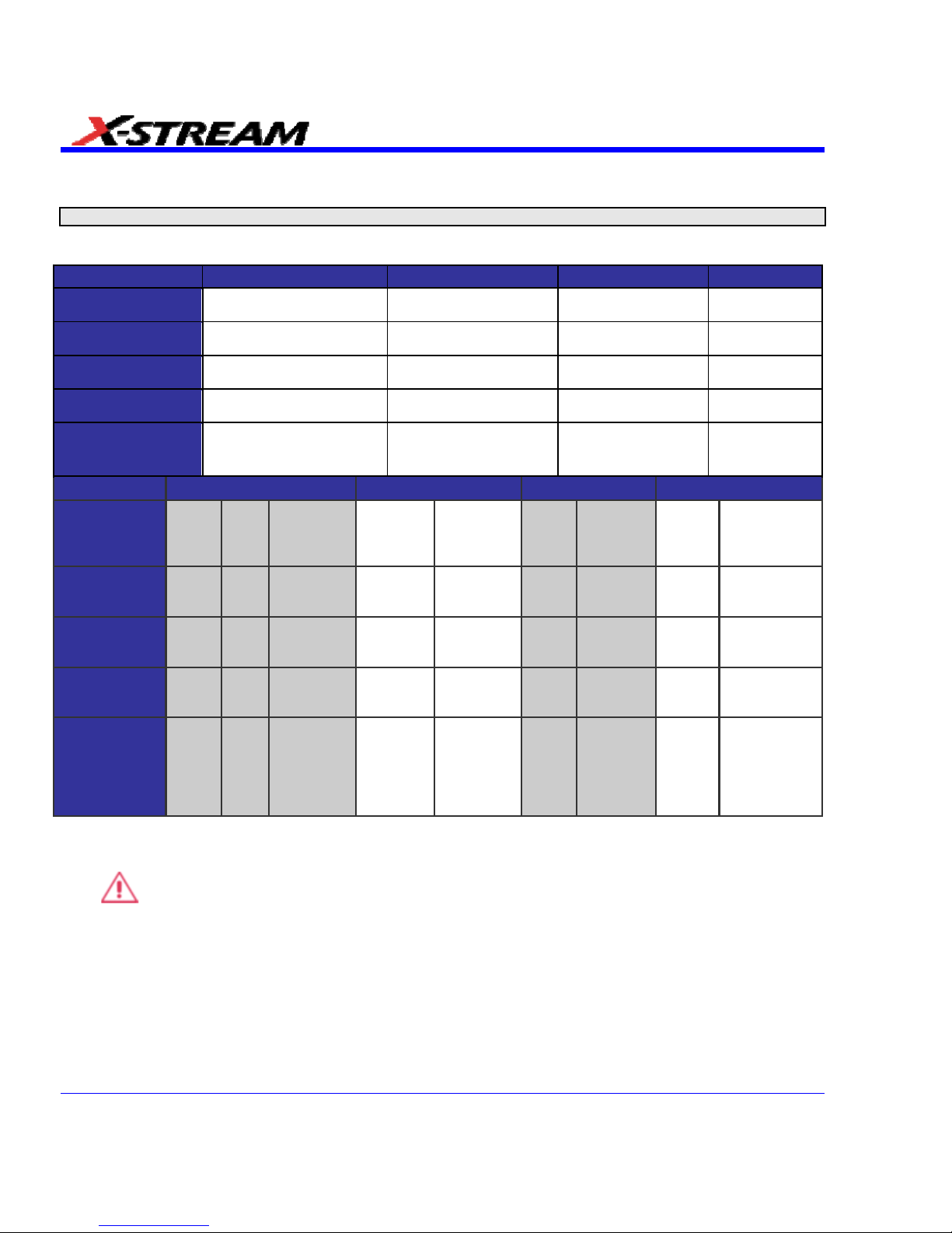
SDA SPECIFICATIONS
Note: Specifications are subject to change without notice.
Vertical System
SDA 6000/6000A/6020 SDA 5000/5000A SDA 4000A/4020 SDA 3010
Analog Bandwitdth
at 50 Ω (-3 dB)
6 GHz 5 GHz 4 GHz 3 GHz
Rise Time
(10-90% Typical)
75 ps 90 ps 105 ps 150 ps
Rise Time
(20-80% Typical)
NA NA NA NA
Number of Input
Channels
4 4 4 4
Bandwidth
Limiters
20 MHz, 200 MHz, 1 GHz,
3 GHz, 4 GHz
20 MHz, 200 MHz, 1
GHz, 3 GHz, 4 GHz
20 MHz, 200 MHz, 1
GHz, 3 GHz
20 MHz, 200
MHz, 1 GHz
SDA 18000 SDA 13000 SDA 11000 SDA 9000
Analog
Bandwitdth at
50 Ω
(-3 dB)
18
GHz
11
GHz
6 GHz 13 GHz 6 GHz
11
GHz
6 GHz 9 GHz 6 GHz
Rise Time
(10-90%
Typical)
27 ps
40
ps
75 ps 35 ps 75 ps 40 ps 75 ps 49 ps 75 ps
Rise Time
(20-80%
Typical)
19 ps
28
ps
NA 25 ps NA 28 ps NA NA NA
Number of
Input
Channels
1 1 4, 2, or 1 2 or 1 4 or 2 or 1 2 or 1 4 or 2 2 or 1 4 or 2
Bandwidth
Limiters
Full Full
20 MHz,
200 MHz,
1 GHz, 3
GHz, 4
GHz
Full
20 MHz,
200 MHz,
1 GHz, 3
GHz, 4
GHz
Full
20 MHz,
200
MHz, 1
GHz, 3
GHz, 4
GHz
Full
20 MHz, 200
MHz, 1 GHz,
3 GHz, 4
GHz
• Input Impedance: 50 ±2%
• Input Coupling: DC, GND (SDA 3010: DC, GND, DC 1M, AC 1M)
•
Maximum Input: ±4 V
peak
(±5 V
rms
)
• Vertical Resolution: 8 bits; up to 11 bits with enhanced resolution (ERES)
• Sensitivity: 2 mV to 1 V/div, < 10 mV/div through zoom
• DC Gain Accuracy: ±1.5% of full-scale
• Offset Range (excluding SDA 3010): ±750 mV (or more) @ 2 mV to 195 mV/div; ±4 V @
195 mV to 1 V/div
• Offset Range (SDA 3010): ±700 mV @ 2-4.99 mV/div, ±1.5 V @ 5-100 mV/div, ±10 V @
0.102-1 V/div (@ 50 ), ±20 V @ 0.102-2 V/div (@ 1 M)
28 SDA-OM-E Rev H
Page 29
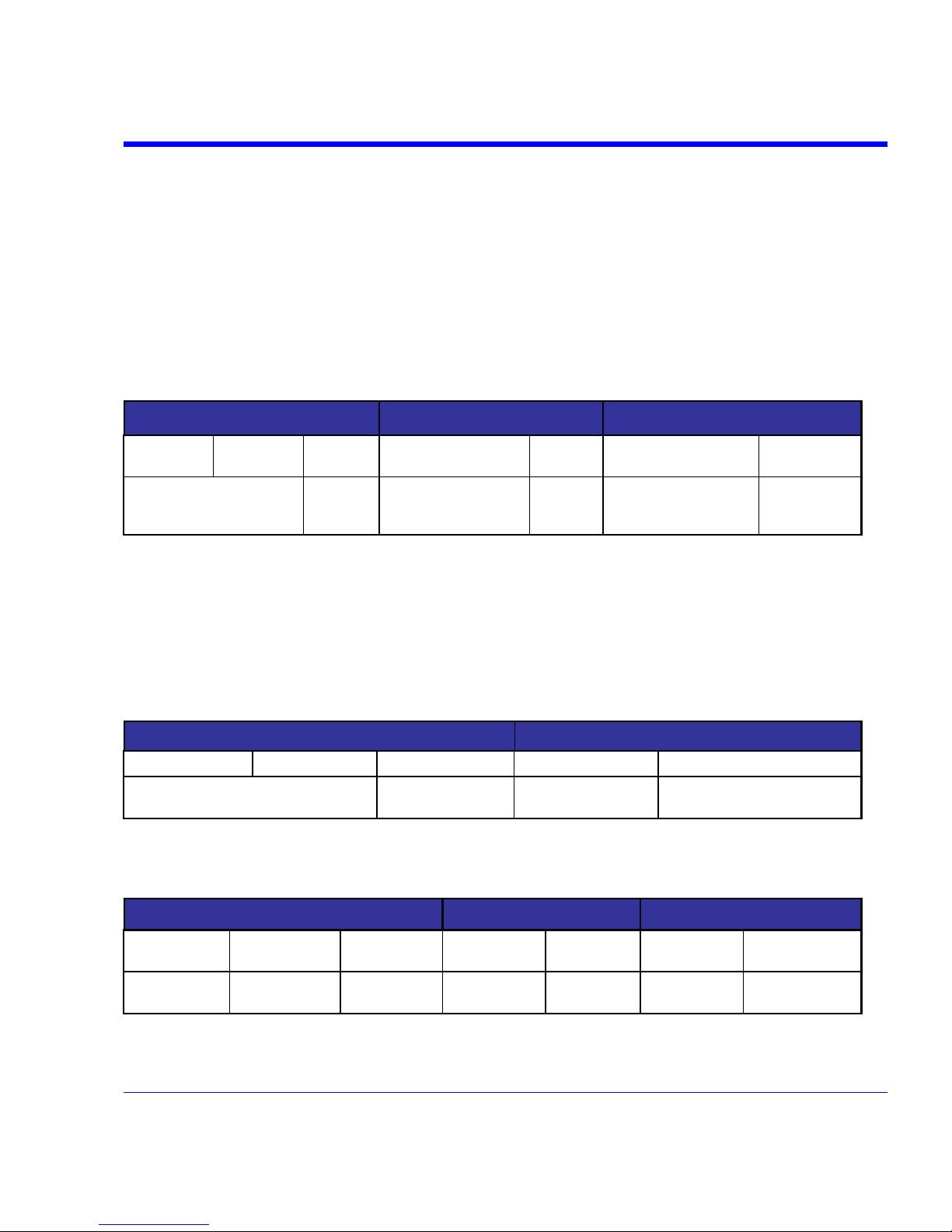
SDA Operator’s Manual
SDA-OM-E Rev H 29
Horizontal System
• Timebases: Internal timebase common to 4 input channels; an external clock may be applied
at the Auxiliary Input (SDA 6020 only)
• Math & Zoom Traces: 8 math/zoom traces standard
• Clock Accuracy: ≤ 1 ppm @ 0 to 40 degrees C (SDA 3010 10 ppm @ 0 to 40 degrees C)
• Time Interval Accuracy: 0.06/SR + (1 ppm x Reading) (rms);
SDA 3010: 0.06/SR + (10 ppm x Reading) (rms)
• Sample Rate + Delay Time Accuracy: ±1 ppm @ 25 degrees C (SDA 3010: ±5 ppm 10 s
interval)
Jitter Noise Floor
SDA 18000 SDA 13000/11000 SDA 9000
18 GHz/Ch
Mode
11 GHz/Ch
Mode
6 GHz/Ch
Mode
13/11 GHz/Ch Mode
6 GHz/Ch
Mode
9 GHz/Ch Mode
6 GHz/Ch
mode
< 350 fs rms measured with
35 ps rise time (typical)
1 ps rms
(typical)
< 350 fs rms measured
with 35 ps rise time
(typical)
1 ps rms
(typical)
< 350 fs rms measured
with 35 ps rise time
(typical)
1 ps rms
(typical)
• SDA 6020, 6000x, 5000x, 4020, 4000x, 3010: 1 ps rms (typical)
• External Clock Frequency: 30 MHz to 2 GHz / 50 impedance applied at the auxiliary
input (except SDA X000A) 30 MHz to 1 GHz / 50 impedance applied at the auxiliary input
(SDA 3010)
• External Reference Clock Frequency: 100 MHz / 50 (except SDA 11000 and 9000)
• Trigger and Interpolator Jitter: 2.5 ps rms
• Time per Division Range: 20 ps to 1000 s/div (10 s/div in Auto-trigger mode)
SDA 18000 SDA 13000/11000
18 GHz/Ch Mode 11 GHz/Ch Mode 6 GHz/Ch Mode 13/11 GHz/Ch Mode 6 GHz/Ch Mode
10 ps/div to 50 µs/div (Std. memory)
10 ps/div to 500 µs/div (-XL memory)
20 ps/div to 10 s/div
10 ps/div to 50 µs/div
(Std memory)
20 ps/div to 10 s/div
(Std memory)
Acquisition System
Single-Shot Sample Rate/Ch: 10 GS/s (SDA 6020 and 4020: 20 GS/s)
SDA 18000 SDA 13000/11000 SDA 9000
18 GHz/Ch
Mode
11 GHz/Ch
Mode
6 GHz/Ch
Mode
11 GHz/Ch
Mode
6 GHz/Ch
Mode
9 GHz/Ch
Mode
6 GHz/Ch mode
60 GS/s on 1
Ch
40 GS/s on 1 Ch
20 GS/s on 4,
2, or 1 Ch
40 GS/s on 4 or
2 Ch
20 GS/s on 2
or 1 Ch
40 GS/s on 2 or
1 Ch
20 GS/s on 4 or 2
Ch
Page 30
30 SDA-OM-E Rev H
Memory
• SDA 6020/4020: 20 Mpts/Ch. Option SDA-XL: 25 Mpts/Ch, 50 Mpts/Ch for 2 or 1
• Ch.SDA6000A XXL/SDA4000A XXL: 50 Mpts/Ch, 100 Mpts/Ch for 2 or 1 Ch
• SDA3010: 10 Mpts/Ch, 20 Mpts/Ch for 2 or 1 Ch. Option SDA-XL: 25 Mpts/Ch, 50 Mpts.Ch
for 2 or 1 Ch.
SDA 18000/13000/11000/9000
SDA 18000 SDA 13000/11000 SDA 9000
18 GHz/Ch
Mode
11 GHz/Ch
Mode
6 GHz/Ch
Mode
13/11 GHz/Ch
Mode
6 GHz/Ch
Mode
9 GHz/Ch
Mode
6 GHz/Ch
mode
Channels 1 1 4 2 4 2 4
Std Memory 60M 40M 20M 40M 20M 40M 20M
XL Memory Option 150M 100M 50M 100M 50M 100M 50M
Acquisition Modes
• Random Interleaved Sampling (RIS): 200 GS/s for repetitive signals (SDA
18000/13000/11000/9000: RIS mode is available in 6 GHz mode only)
• Single-Shot: For transient and repetitive signals: 20 ps/div to 1000 s/div; (SDA
18000/13000/11000/9000 in 6 GHz mode only): 20 ps/div to 1 µs/div
• Sequence: 2 to 40,000 segments (number of segments depends upon memory options)
• Intersegment Time: 6 µs (typical)
Acquisition Processing
• Averaging: Summed averaging to 1 million sweeps; Continuous averaging to 1 million
sweeps
• Enhanced Resolution (ERES): From 8.5 to 11 bits vertical resolution
• Envelope (Extrema): Envelope, floor, roof for up to 1 million sweeps
Triggering System
• Modes: Normal, Auto, Single, and Stop
• Sources: Any input channel, External, EXT X10, EXT/10, or line; slope and level unique to
each source (except line trigger; disabled channels cannot be used as a trigger source in
SDA 18000, SDA13000, SDA 11000, or SDA 9000 when operating in 18 GHz, 13 GHz, 11
GHz, or 9 GHz modes.)
• Coupling Modes: DC
• Pre-trigger delay: 0 to 100% of memory size (adjustable in 1% increments)
• Post-trigger delay: smaller of 0 to 10,000 divisions or 86400 seconds
• Hold-off by time or events: Up to 20 s or from 1 to 99,999,999 events
• Internal trigger range: ±4.1 div from center
• Max. trigger frequency: Up to 5 GHz with Edge Trigger; 750 MHz with SMART Trigger
Page 31

SDA Operator’s Manual
• External trigger input range: AUX (±0.4 V); AUX X10 (±0.04 V); AUX /10 (±4 V) Not
available on SDA 6000A, SDA 5000A, SDA 4000A
Automatic Setup
• Auto Setup: Automatically sets timebase, trigger, and sensitivity to display a wide range of
repetitive signals.
• Vertical Find Scale: Automatically sets vertical sensitivity and offset for the selected
channels to display a waveform with maximum dynamic range.
Probes
• Probes: A variety of optional passive and active probes are available.
• Probe System: ProLink with ProBus automatically detects and supports a variety of
compatible probes; Supports ProLink SMA or BNC input adapters.
• Scale Factors: Automatically or manually selected depending on probe used.
Basic Triggers
Edge/Slope/Line: Triggers when signal meets slope and level condition.
SMART Triggers
• State or Edge Qualified: Triggers on any input source only if a defined state or edge
occurred on another input source. Delay between sources is selectable by time or events
• Dropout: Triggers if signal drops out for longer than selected time between 2 ns and 20 s
• Pattern Logic: Combination (AND, NAND, OR, NOR) of 5 inputs (maximum of 3 or 4 inputs;
External Trigger not available on the SDA 6000A, SDA 5000A, and SDA 4000A; 4, 3, or 2 Ch
+ External Trigger on SDA 18000/13000/11000/9000). Each source can be high, low, or don't
care. Triggers at the start or end of the pattern.
SMART Triggers with Exclusion Technolo gy
• Glitch: Triggers on positive or negative glitches with widths selectable from 600 ps to 20 s or
on intermittent faults.
• Signal or Pattern Width: Triggers on positive or negative pulse widths selectable from 600
ps to 20 s or on intermittent faults.
• Signal or Pattern Interval: Triggers on intervals selectable between 2 ns and 20 s.
SDA-OM-E Rev H 31
Page 32

32 SDA-OM-E Rev H
Serial Trigger
Available on SDA 6000A (XXL), SDA 5000A (XXL), SDA 4000A (XXL)
Data Type
NRZ encoded for clock extraction (needs
edge density > 20%)
Sensitivity
1 division minimum and at least 10 mV
p-p
Min. Frequency
50 MHz
Max. Frequency
2.7 GHz
Serial Trigger Length
up to 32 bits
Clock/Data Output Connector Type
SMA
Clock/Data Output
1/2 amplitude, AC coupled LVPCL
Clock/Data Output Voltage Swing (into 50 Ω)
400 mV typical
Clock /Data Output Rise/Fall Time
200 ps typical
Recovered CLK and DATA Jitter
0.015 UI rms typical
Recovered CLK and DATA Phase Relationship
Data is centered on the rising edge of the
clock
Source
Channel 4 only
Trigger Sensitivity
1 division minimum and at least 10 mV
p-p
Clock Recovery
custom filter settings
damping factor
natural frequency
number of poles
Standard PLL settings
(FC, Golden, PCIe, DVI, Custom)
Jitter Analysis
advanced (peak-peak, rms)
basic (Tj, Rj, Dj)
bathtub curve
conventional
cycle-cycle jitter
Dj breakdown
edge to edge (data to data)
edge to reference (data to
clock)
effective
filtered jitter
half-period jitter
ISI plot
jitter histogram
jitter wizard
MJSQ
period jitter
periodic jitter (Pj) with peak frequency listing
synchronous N-cycle with bit pattern display
TIE clock jitter
TIE jitter
Page 33

SDA Operator’s Manual
SDA-OM-E Rev H 33
Math Tools – Standard
Display up to eight math function traces (F1 to F8). The easy-to-use graphical interface simplifies
setup of up to two operations on each function trace. Function traces can be chained together to
perform math-on-math.
absolute value
average (summed)
average (continuous)
derivative
deskew (resample)
difference ()
enhanced resolution (to 11 bits vertical)
envelope
exp (base e)
exp (base 10)
fft (power spectrum, magnitude phase up to 25
kpts)
floor
histogram of 1,000 events
integral
invert (negate)
log (base e)
log (base 10)
product (x)
ratio (/)
reciprocal
rescale (with units)
roof
(sin x)/x
square
square root
sum (+)
trend (datalog) of 1,000 events
zoom (identity)
Automated Measure Tools – Standard
These standard tools allow the display of any 8 parameters together with statistics, including their
average, high, low, and standard deviations. Histicons provide a fast, dynamic view of parameters
and wave shape characteristics.
amplitude
area
base
cycles
data
delay
delay
duty cycle
duration
falltime (90-10%, 80-20%, @ level)
frequency
first
last
level@x
maximum
mean
median
minimum
number of points
+overshoot
overshoot
peak-to-peak
period
phase
risetime (10-90%, 20-80%, @ level)
rms
std. deviation
top
width
time @ minimum (min.)
time @ maximum (max.)
time @ level
time @ level from trigger
x @ max
x @ min
Page 34

34 SDA-OM-E Rev H
Pass/Fail Testing
Simultaneously test multiple parameters against selectable parameter limits or pre-defined
masks. Pass or fail conditions can initiate actions including document to local or networked files,
email the image of the failure, save waveforms, send a pulse out of the front panel auxiliary BNC
output, or (with the GPIB option) send a GPIB SRQ.
Advanced Math Package (XMATH) – Standard
This package provides a comprehensive set of signal WaveShape Analysis tools providing insight
into the wave shape of complex signals. Additional capability provided by XMATH includes:
• 8 math traces total (4 additional)
• Parameter math add, subtract, multiply, or divide two different parameters
• Histograms expanded with 19 histogram parameters and up to 2 billion events
• Trend (datalog) of up to 20,000 events
• Track graphs of any measurement parameter
• FFT capability added to include: power averaging, power density, real and imaginary
components, frequency domain parameters, and FFT on up to 25 Mpts
• Narrow-band power measurements
• Auto-correlation function
• Sparse function
• Cubic and Quadratic Interpolation
Jitter and Timing Analysis Package (JTA2) – Standard
This package provides jitter timing and analysis using time, frequency, and statistical views for
common timing parameters, and also includes other useful tools.
• Jitter and timing parameters, with Track graphs for the following:
Cycle-Cycle Jitter
N-Cycle
w/ start selection Frequency
Period
Half Period
Width
Time Interval Error
Setup
Hold
Skew
Duty Cycle
Duty Cycle Error
• Edge@lv parameter (counts edges)
• Histograms expanded with 19 histogram parameters and up to 2 billion events
• Trend (datalog) of up to 20,000 events
• Track graphs of all parameters
• Persistence histogram, persistence trace (mean, range, sigma)
Page 35

SDA Operator’s Manual
SDA-OM-E Rev H 35
ASDA-J - Standard
This package includes:
• Edge-to-edge jitter
• Clock jitter
• Filtered jitter
• Effective and MJSQ jitter
• ISI plot of data dependent jitter
• N-cycle jitter plot
• Bit error rate analysis
• Mask violation
8B/10B Protocol Decoding - Standard
Simultaneously translates up to 4 lanes of 8B/10B encoded Serial Data waveforms into symbol
views to allow easier troubleshooting. This allows you to quickly correlate protocol events with the
physical serial data waveform. The decoder operates with 8B/10B encoded data at rates up to
6.25 Gb/s.
Advanced Customization Package (XDEV) – Optional
This package provides a set of tools to modify the analyzer and customize it to meet your unique
needs. Additional capability provided by XDEV includes:
• The ability to create your own measurement parameter or math function using third-party
software packages and display the result in the scope. Supported third-party software
packages include: VBScript (Visual Basic), Excel, MATLAB, Mathcad
• CustomDSO creates your own user interface in a scope dialog box.
• Supports plug-ins
Color Waveform Display
• Type: Color 10.4" flat-panel TFT-LCD with high-resolution touch-screen
• Resolution: SVGA; 800 x 600 pixels
• Realtime Clock: Dates, hours, minutes, seconds displayed with waveform, SNTP support to
synchronize to precision internet clocks
• Number of Traces: Display a maximum of 8 traces. Simultaneously display channel, zoom,
memory, and math traces.
• Grid Styles: Auto, Single, Dual, Quad, Octal, XY, Single + XY, Dual + XY, or Auto
• Waveform Styles: Sample dots joined or dots only
Page 36

36 SDA-OM-E Rev H
Analog Persistence Displ ay
• Analog & Color-Graded Persistence: Variable saturation levels; stores each traces
persistence data in memory.
• Persistence Selections: Select analog, color, or three dimensional.
• Trace Selection: Activate Analog Persistence on all or any combination of traces.
• Persistence Aging Time: Select from 500 ms to infinity.
• Sweeps Displayed: All accumulated, or all accumulated with last trace, highlighted
Zoom Expansion Traces
Display up to 8 Math/Zoom traces.
CPU
• Processor: Intel® Pentium 4 @ 2.53 GHz (or better) with MS Windows® XP Platform
• Processing Memory: Up to 2 Gbytes
Internal Waveform Memory
M1, M2, M3, M4 Internal Waveform Memory (Store full-length waveforms with 16 bits/data point.)
Or store to any number of files limited only by data storage media.
Setup Storage
Front Panel and Instrument Status Save to the internal hard drive, floppy drive or to a USBconnected peripheral device.
Interface
• Remote Control: Via Windows Automation, or via LeCroy GPIB command set
• GPIB Port: (Optional) Supports IEEE-488.2
• Ethernet Port" 10/100Base-T Ethernet interface
• USB Ports: 4 USB ports support Windows compatible devices.
• External Monitor Port: Standard 15-pin D-Type SVGA-compatible
• Parallel Port: 1 standard
Auxiliary Output
• Signal Types: Select from calibrator or control signals output on front panel.
• Calibrator Signal: 5 Hz to 5 MHz square wave or DC Level; 0.0 to +0.5 Volts into 50 (0 to
1 V into 1 M), or TTL Volts (selectable)
• Control Signals: Trigger enabled, trigger out, pass/fail status
Auxiliary Input
Signal Types: Select from External Trigger or External Clock input on front panel.
Page 37

SDA Operator’s Manual
SDA-OM-E Rev H 37
General
• Auto Calibration: Ensures specified DC and timing accuracy is maintained for 1 year
minimum.
• Power Requirements: 100 to 120 VAC at 50/60/400 Hz; 200 to 240 VAC at 50/60 Hz; Power
consumption: 650 VA, 650 W max. (SDA 3010/4000A/5000A/6000A); 800 VA, 800 W max.
(SDA 4020/6020/9000/11000/13000/18000)
Environmental Characteristic s
Temperature
• Operating: 5 to 40 °C
• Storage (non-operating): -20 to +60 °C
Humidity
• Operating: Maximum relative humidity 80% for temperatures up to 31 °C decreasing linearly
to 50% relative humidity at 40 °C
• Storage (non-operating): 5 to 95% RH (non-condensing) as tested per MIL-PRF-28800F
Altitude
• Operating: Up to 2,000 m
• Storage (non-operating): 12,192 m (40,000 ft)
Certifications
CE Compliant, UL and cUL Listed
CE Declaration of Conformity
The oscilloscope meets requirements of EMC Directive 89/336/EEC for Electromagnetic
Compatibility and Low Voltage Directive 73/23/EEC for Product Safety.
EMC Directive: EN 61326/A3:2003
EMC requirements for electrical equipment for measurement,
control, and laboratory use.
Electromagnetic Emissions: EN 55011/A2:2002, Class A Radiated and conducted
emissions (Class A)*
EN 61000-3-2/A2:2005 Harmonic Current Emissions (Class A)
EN 61000-3-3/A2:2005 Voltage Fluctuations and Flickers
(Pst = 1)
* To conform to Radiated Emissions standard, use properly shielded cables on all I/O terminals.
Page 38

Warning
This is a Class A product. In a domestic environment this product may cause radio interference,
in which case the user may be required to take appropriate measures.
Electromagnetic Immunity: EN 61000-4-2/A2:2001* Electrostatic Discharge
(4 kV contact, 8 kV air, 4 kV vertical/horizontal coupling planes)
EN 61000-4-3/A1:2003* RF Radiated Electromagnetic Field
(3 V/m, 80-1000 MHz)
EN 61000-4-4:2004* Electrical Fast Transient/Burst
(1 kV AC Mains, 0.5 kV I/O signal/control)
EN 61000-4-5/A1:2001* Surges
(1 kV AC Mains, 0.5 kV I/O signal/control)
EN 61000-4-6/A1:2001* RF Conducted Electromagnetic Field
(1 kV / 0.5 kV common mode / differential mode - AC Mains)
EN 61000-4-11:2004** Mains Dips and Interruptions
(1 cycle voltage dip, 100% short interruption)
* Meets Performance Criteria "B" limits during the disturbance; product undergoes a temporary
degradation or loss of function of performance which is self recoverable.
** Meets Performance Criteria "C" limits during the disturbance; product undergoes a temporary
degradation or loss of function of performance which requires operator intervention or system
reset.
Low Voltage
Directive:
EN 61010-1:2001
Safety requirements for electrical equipment for measurement, control, and
laboratory use.
The oscilloscope has been qualified to the following EN 61010-1 limits:
Installation Categories II (Mains Supply Connector) & I (Measuring Terminals)
Pollution Degree 2 (Normally only dry non-conductive pollution occurs.
Occasionally a temporary conductivity caused by condensation must be
expected.)
Protection Class I (Provided with terminal for protective ground)
UL and cUL Certifications: UL Standard: UL 61010-1 2
n
d
Edition
Canadian Standard: CSA-C22.2 No. 61010-1-04
Physical Dimensions
• Dimensions (HWD): 264 mm x 397 mm x 491 mm; 10.4" x 15.6" x 19.3" (height excludes
feet); SDA 18000/13000/11000/9000: 310 mm x 447 mm x 500 mm, 12.2" x 17.6" x 19.7
• Weight: 18 kg; 39 lbs. (SDA 6020: 23 kg; 49 lbs.)
• Shipping Weight: 24 kg (53 lbs.); SDA 6020, 4020: 29 kg (63 lbs.); SDA
18000/13000/11000/9000: 36 kg, (80 lbs.)
38 SDA-OM-E Rev H
Page 39

SDA Operator’s Manual
Warranty and Service
3-year warranty; calibration recommended annually.
Optional service programs include extended warranty, upgrades, and calibration services.
Optical Reference Receiver (with OE425/OE455)
4th order Bessel-Thompson filter response at the following data rates:
SDA 3010/4000A/4020/5000A/6020/
6000A/9000/11000/13000/18000
SONET/SDH
OC-1/STM0 (51.84 Mb/s)
OC-3/STM1 (155.52 Mb/s)
OC-12/STM4 (622.08 Mb/s)
OC-48/STM16 (2488.3 Mb/s)
Fibrechannel
FC133 (132.7 Mb/s)
FC266 (265.6 Mb/s)
FC531 (531.2 Mb/s)
FC1063 (1063.5 Mb/s)
FC2125 (2127 Mb/s)
Gigabit Ethernet
1.25 Gb/s
InfiniBand
2.25 Gb/s (2127 Mb/s)
User-Defined
Any rate up to 3.5 Gb/s
Software Clock Recovery System
SDA 4000A/SDA 5000A/SDA 6000A
Channel
Software-based clock recovery using golden PLL for data rates
up to 3.5 Gb/s
PLL Bandwidth
Single pole w/ adjustable cut-off frequency
Jitter
Same as time base: 1ps rms
SDA-OM-E Rev H 39
Page 40

Communications Mask Testing
SDA
3010/4000A/4020/5000A/6020/6000A/9000/11000/13000/18000
SONET/SDH
OC-1/STM0
OC-3/STM1 Optical
OC-12/STM4 Optical
OC-48/STM16 Optical
Ethernet IEEE Std 802.3 and
ANSI X3.263-1995
1000Base-SX Short Wave Optical
1000Base-LX Long Wave Optical
Fibre Channel Electrical
(ANSI X3.303-1997)
FC133E, FC266E, FC531E, FC1063E
IEEE 1394b (draft)
S400 Optical
S400b T1
S400b T2
S800 Optical
S800b T1
S800b T2
S1600 Optical
S1600b T1
S1600b T2
Serial ATA
G1, G1 Rx, G1 Tx
G2, G2 Rx, G2 Tx
DVI (rev.1.0)
Transmit normalized, Receiver Low/high
InfiniBand (draft)
2.5 Gb/s Optical
2.5 Gb/s Electrical
Jitter Testing
• Data Measurements: Period, Frequency, TIE
• Clock Measurements: Frequency, Period, Half Period, Cycle-Cycle, N-Cycle, Positive Cy-
Cy Duty, Negative Cy-Cy Duty, Clock TIE
• Analysis: Tj, DCD, DDj, Pj, Rj, Dj, Rje, Dje
• Delta Time Accuracy: 1 ps rms at 20 GS/s
40 SDA-OM-E Rev H
Page 41

SDA Operator’s Manual
Bit Error Rate (optional)
SDA 4000A/SDA 5000A/SDA 6000A
Data Rate
2.7 Gb/s
Maximum capture buffer
size (bits)
20 GS/s at 2.5 Gb/s data rate
(8 samples/bit)
Std.
VL (32M)
XL (50M)
XXL (100M)
1M
3M
5M
10M
Minimum Detectable BER
(single acquisition)
1 X 10
-
7
SDA-OM-E Rev H 41
Page 42
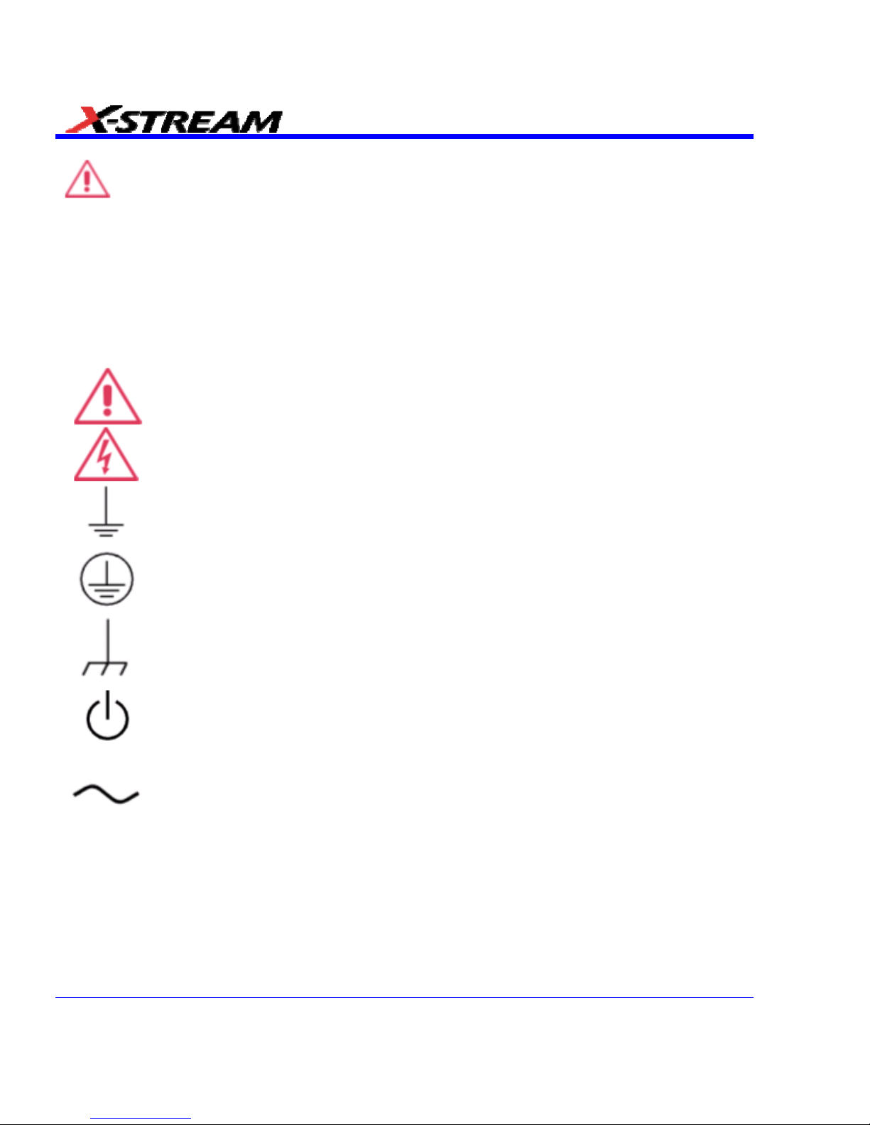
SAFETY
Safety Requirements
This section contains information and warnings that must be observed to keep the instrument
operating in a correct and safe condition. You are required to follow generally accepted safety
procedures in addition to the safety precautions specified in this section.
Safety Symbols
Where the following symbols appear on the instrument’s front or rear panels, or in this manual,
they alert you to important safety considerations.
This symbol is used where caution is required. Refer to the accompanying
information or documents in order to protect against personal injury or damage to
the instrument.
This symbol warns of a potential risk of shock hazard.
This symbol is used to denote the measurement ground connection.
This symbol is used to denote a safety ground connection.
This symbol is used to denote a grounded frame or chassis terminal.
This symbol shows that the switch is a Standby (power) switch. When it is
pressed, the scope’s state toggles between operating and Standby mode. This
switch is not a disconnect device. The instrument can only be placed in a complete
Power Off state by unplugging the power cord from the AC supply.
This symbol is used to denote Alternating Current.
CAUTION
The CAUTION sign indicates a potential hazard. It calls attention to a procedure,
practice or condition which, if not followed, could possibly cause damage to
equipment. If a CAUTION is indicated, do not proceed until its conditions are fully
understood and met.
WARNING
The WARNING sign indicates a potential hazard. It calls attention to a procedure,
practice or condition which, if not followed, could possibly cause bodily injury or
death. If a WARNING is indicated, do not proceed until its conditions are fully
understood and met.
42 SDA-OM-E Rev H
Page 43
SDA Operator’s Manual
CAT I
Installation (Overvoltage) Category rating per EN 61010-1 safety standard and is
applicable for the oscilloscope front panel measuring terminals. CAT I rated
terminals must only be connected to source circuits in which measures are taken
to limit transient voltages to an appropriately low level.
Operating Environment
The instrument is intended for indoor use and should be
operated in a clean, dry environment. Before using this
product, ensure that its operating environment will be
maintained within these parameters:
Temperature: 5 to 40
°
C
Humidity: Maximum relative humidity 80% for
temperatures up to 31
°
C decreasing linearly to 50%
relative humidity at 40
°
C.
Altitude: Up to 2,000 m
Note: Direct sunlight, radiators, and other heat sources should be
taken into account when assessing the ambient temperature.
WARNING
The scope must not be operated in
explosive, dusty, or wet
atmospheres.
CAUTION
Protect the scope’s display touchscreen from excessive impacts with
foreign objects.
CAUTION
Do not exceed the maximum
specified front panel terminal (CH1,
CH1, CH2, CH3, CH4, AUX IN) voltage
levels. Refer to Specifications for
more details.
SDA-OM-E Rev H 43
Page 44

Installation (Overvoltage) Category II refers to local
distribution level, which is applicable to equipment
connected to the mains supply (AC power source).
Installation (Overvoltage) Category I refers to signal
level, which is applicable to equipment measuring
terminals that are connected to source circuits in
which measures are taken to limit transient voltages to
an appropriately low level.
Pollution Degree 2 refers to an operating environment
where normally only dry non-conductive pollution
occurs. Occasionally a temporary conductivity caused
by condensation must be expected.
Protection Class 1 refers to a grounded equipment, in
which protection against electric shock is achieved by
Basic Insulation and by means of a connection to the
protective ground conductor in the building wiring.
Note:
The design of the instrument has been verified to
conform to
EN 61010-1 safety standard per the following
limits:
Installation (Overvoltage) Categories II (Mains
Supply Connector) & I (Measuring Terminals)
Pollution Degree 2
Protection Class I
Cooling
The instrument relies on forced air cooling with internal
fans and ventilation openings. Care must be taken to
avoid restricting the airflow around the apertures (fan
holes) at the sides and rear of the scope. To ensure
adequate ventilation it is required to leave a 10 cm (4
inch) minimum gap around the sides and rear of the
instrument.
CAUTION
Do not block the ventilation holes
located on both sides and rear of the
scope.
The instrument also has internal fan control circuitry that
regulates the fan speed based on the ambient
temperature. This is performed automatically after startup with no manual intervention required.
CAUTION
Do not allow any foreign matter to
enter the scope through the
ventilation holes, etc.
AC Power Source
100 to 120 VAC (±10%) AC at 50/60/400 Hz;
200 to 240 VAC (±10%) AC at 50/60 Hz; Automatic AC
voltage selection; Installation Category: 300V CAT II
No manual voltage selection is required because the
instrument automatically adapts to line voltage.
Note:
The instrument automatically adapts itself to the
AC line input within the following ranges:
Voltage Range
90 to 132 VAC
180 to 264 VAC
Frequency Range
45 to 440 Hz
45 to 66 Hz
44 SDA-OM-E Rev H
Page 45

SDA Operator’s Manual
Power Consumption
SDA 6020, 4020, 9000, 11000, 13000, 18000: 800 watts
(800 VA) depending on accessories installed (internal printer,
probes, PC port plug-ins, etc.)
SDA 4000A, 5000A, 6000A: 650 watts (650 VA)
The power supply of the scope is protected against
short circuit and overload by a 5x20 mm fuse (T10.0
A/250 V). See “Fuse Replacement” section for
replacement instructions.
Power and Ground Connections
The instrument is provided with a grounded cord set
containing a molded three-terminal polarized plug and a
standard IEC320 (Type C13) connector for making line
voltage and safety ground connection. The AC inlet
ground terminal is connected directly to the frame of the
instrument. For adequate protection against electrical
shock hazard, the power cord plug must be inserted into
a mating AC outlet containing a safety ground contact.
WARNING
Electrical Shock Hazard!
Any interruption of the protective
conductor inside or outside of the
scope, or disconnection of the safety
ground terminal creates a hazardous
situation.
Intentional interruption is prohibited.
In Standby mode the scope is still connected to the AC
supply. The instrument can only be placed in a complete
Power Off state by physically disconnecting the power
cord from the AC supply.
The scope should be positioned to allow easy access to
the socket-outlet. To disconnect the scope from the AC
supply, unplug the instrument’s power cord from the AC
outlet after the scope is placed in Standby state.
See “Standby (Power) Switch and Scope Operational
States” section for more information.
CAUTION
The outer shells of the front panel
terminals (CH1, CH2, CH3, CH4, AUX
IN, AUX OUT) are connected to the
instrument’s chassis and therefore
to the safety ground.
SDA-OM-E Rev H 45
Page 46

Standby (Power) Switch and Scope Operational States
The front Standby (Power) switch controls the operational state of the scope. This toggle switch is
activated by momentarily pressing and releasing it. The color of the LED below the switch
indicates the status of the scope as follows:
• On (LED Green)* - scope is fully-powered and operational
• Standby (LED Off)* - scope is powered off (except for some “housekeeping” circuits)
• Standby (LED Red) - scope’s computer subsystems (hard drive, etc.) are in Standby
(reduced power) mode. All other scope subsystems are fully-powered.
* Factory Settings
The scope’s factory settings result in two basic scope states: On (LED Green) or Standby (LED
Off). In Standby (LED Off), the scope is powered off with the exception of some “housekeeping”
circuitry (approximately 12 watts of dissipation). The scope can only be placed in a complete
power off state by unplugging the instrument’s power cord from the primary power source (AC
outlet). It is recommended that the power cord be unplugged from the AC outlet when the scope
is not used for extended periods of time.
The scope can be changed back to the original factory settings using the “Power Options
Properties” menu in Windows at the following the path: Settings Î Power Î Options. It is
important to note that the Windows Power Option named “Standby” only provides control of the
scope’s computer subsystems (CPU, hard drive, etc.) and does not affect the other subsystems
within the scope. In general, these other subsystems remain fully-powered. For additional
information on setting these Power Options, see the Windows Help menu or other related
technical documentation. In terms of control buttons, this scope uses only a power button/switch.
Therefore, sleep button references are not applicable.
The scope can always be put in the Standby state (LED Off) Power Off (except for some
“housekeeping” circuits) by pressing and holding the Standby toggle switch for approximately 5
seconds.
Fuse Replacement
Set the scope’s Standby (power) switch to
Standby mode (LED off) and disconnect the
power cord before inspecting or replacing the
fuse. Open the black fuse holder (located at the
rear of the instrument directly to the right of the
AC inlet) using a small, flat-bladed screwdriver.
Remove the old fuse, replace it with a new 5x20
mm “T” rated 10.0 A/250 V fuse, and reinstall the
fuse holder.
WARNING
For continued fire protection at all line
voltages, replace fuse with the specified
type and rating only. Disconnect the
power cord before replacing fuse.
46 SDA-OM-E Rev H
Page 47

SDA Operator’s Manual
Calibration
The recommended calibration interval is one year and should be performed by qualified
personnel only.
Cleaning
Clean only the exterior of the instrument, using a damp,
soft cloth. Do not use chemicals or abrasive elements.
Under no circumstances allow moisture to penetrate the
instrument. To avoid electrical shock, unplug the power
cord from the AC outlet before cleaning.
WARNING
Electrical Shock Hazard! No
operator serviceable parts inside. Do
not remove covers.
Refer servicing to qualified
personnel.
Abnormal Conditions
Operate the instrument only as intended by the
manufacturer.
If you suspect the scope’s protection has been impaired,
disconnect the power cord and secure the instrument
against any unintended operation.
The scope’s protection is likely to be impaired if, for
example, the instrument shows visible damage or has
been subjected to severe transport stresses.
Proper use of the instrument depends on careful
reading of all instructions and labels.
WARNING
Any use of the scope in a manner
not specified by the manufacturer
may impair the instrument’s safety
protection. The instrument and
related accessories should not be
directly connected to human
subjects or used for patient
monitoring.
SDA-OM-E Rev H 47
Page 48

BASIC CONTROLS
Alternate Access Methods
Note: The instrument often provides more than one way to access dialogs and menus.
Mouse and Keyboard Operation
Touch-screen operation is used for most procedures explained in our manuals. However, if you
have a mouse connected to the instrument, you can also be used to click on objects. Also, if you
have a keyboard connected, it can be used instead of the virtual keyboard provided in the
instrument.
Use only a USB connection for a mouse (if used).
Toolbar Buttons
The procedures also focus on the use of the menu bar at the top of the screen to access dialogs
and menus. However, on several dialogs common functions are accessible from a row of buttons
that save you a step or two in accessing their dialogs. For example, at the bottom of the Channel
Setup dialog, these buttons perform the following functions:
Calls up the Measure menu. You can then select a parameter from this menu
without leaving the Channel Setup dialog. The parameter automatically appears
below the grid.
Creates a zoom trace of the channel trace whose dialog is currently displayed.
Calls up the Math menu. You can then select a math function from this menu
without leaving the Channel Setup dialog. A math trace of the channel whose
dialog is currently open is automatically displayed.
Loads the channel trace into the next available memory location (M1 to M4).
Automatically performs a vertical scaling that fits the waveform into the grid.
Automatically moves the channel trace whose dialog is currently open onto the
next grid. If you have only one grid displayed, a new grid will be created
automatically, and the trace moved.
Enables you to attach identifying labels to your waveforms. The labels are
preserved when the waveform is saved as a LabNotebook entry and when saved
to file.
48 SDA-OM-E Rev H
Page 49

SDA Operator’s Manual
Another example includes the buttons appearing at the bottom of the Measure Px dialogs. Each
button opens a menu from which to choose a math trace (F1 to Fx - The number of math traces
available depends on the software options loaded on your scope, so please refer to your scope
specifications) to display the functions named in the following buttons:
By using these buttons you can remain in the Measure dialog and set up other options.
Trace Descriptors
Vertical and horizontal trace descriptors (labels) are displayed below the grid. They provide a
summary of your channel, timebase, and trigger settings. To make adjustments to these settings,
touch the respective label to display the setup dialog for that function.
Channel trace labels show the vertical settings for the trace,
as well as cursor information if cursors are in use. In the title
bar of the label are also included indicators for (SinX)/X
interpolation, waveform inversion (INV), deskew (DSQ),
coupling (DC/GND), bandwidth limiting (BWL), and
averaging (AVG). These indicators have a long and short
form.
Besides channel traces, math and parameter measurement
labels are also displayed. Labels are displayed only for
traces that are turned on.
The title bar of the TimeBase label shows the trigger delay
setting. Time per division and sampling information is given
below the title bar.
The title bar of the Trigger label shows the trigger mode:
Auto, Normal, or Stopped. Below the title bar is given the
coupling (DC), trigger type (Edge), source (C1), level (0
mV), and slope (Positive).
SDA-OM-E Rev H 49
Page 50

Shown (as follows) the TimeBase and Trigger labels are
setup information for horizontal cursors, including the time
between cursors and the frequency.
Trace Annotation
The instrument gives you the ability to add an identifying label, bearing your own text, to a
waveform display:
For each waveform, you can create multiple labels and turn them all on or all off. Also, you can
position them on the waveform by dragging or by specifying an exact horizontal position.
50 SDA-OM-E Rev H
Page 51

SDA Operator’s Manual
Annotating a Waveform
1. Touch the waveform you want to annotate, and then Set label... in the pop-up menu. A dialog
box opens in which to create the label. If you are creating a label for the first time for this
waveform, Label1 is displayed with default text. If you are modifying an existing label, under
Labels touch the label you want to change.
Please Note the Following:
• If the dialog for the trace you want to annotate is currently displayed, you can touch the label button
at the bottom to display the Trace Annotation setup dialog.
• You may place a label anywhere you want on the waveform. Labels are numbered sequentially according to the
order in which they are added, and not according to their placement on the waveform.
2. If you want to change the label's text, touch inside the Label Text field. A pop-up keyboard
appears for you to enter your text. Touch O.K. on the keyboard when you are done. Your
edited text will automatically appear in the label on the waveform.
3. To place the label precisely, touch inside the Horizontal Pos. field and enter a horizontal
value, using the pop-up numeric keypad.
4. To add another label, touch the Add label button. To delete a label, select the label from the
list, then touch the Remove label button.
5. To make the labels visible, touch the View labels checkbox.
SDA-OM-E Rev H 51
Page 52

Turning on a Channel Trace Label
Note: If you want to display each trace on its own grid automatically, enable Autogrid by touching Display in the menu
bar, then Autogrid in the drop-down menu.
• On the front panel, press a channel select button, such as , to display the trace label for
that input channel and turn on the channel.
• To turn on a math function trace, touch Math in the menu bar, then Math Setup... in the dropdown menu. Touch the On checkbox for the trace you want to activate.
• You can also quickly create traces (and turn on the trace label) for math functions and
memory traces, without leaving the Vertical Adjust dialog, by touching the icons at the bottom
of the Vertical Adjust dialog:
Whenever you turn on a channel, math, or memory trace via the menu bar, the dialog at the
bottom of the screen automatically switches to the vertical setup or math setup dialog for that
selection.
You can configure your traces from here, including math setups.
The channel number appears in the Vertical Adjust tab of the "Vertical Adjust" dialog, signifying
that all controls and data entry fields are dedicated to the selected trace.
52 SDA-OM-E Rev H
Page 53

SDA Operator’s Manual
INSTALLATION
Software
Checking the Scope Status
To find out the scope's software and hardware configuration, including software version and
installed options, proceed as follows:
• In the menu bar, touch
.
• Touch the
tab.
You can find information related to hard drive memory, etc. as follows:
1. Minimize the instrument application by touching , then selecting Minimize in the drop-
down menu.
2. Touch the Start taskbar button and, per usual Windows® operation, open Windows Explorer.
Default Settings
DDA, SDA, and WaveRunner DSOs
On your front panel, the D
EFAULT SETUP push button does not exist. For these instruments,
therefore, to recall a default setup
1. Press the S
AVE/RECALL push button to the left of the DRIVE ANALYSIS push button.
Note: You can also touch File in the menu bar, then Recall Setup... in the drop-down menu.
2. Touch the "Recall Setup" tab in the dialog.
3. Then touch the on-screen Recall Default button:
Adding a New Option
To add a software option you need a key code to enable the option. Call LeCroy Customer
Support to place an order and receive the code.
To add the software option do the following:
1. In the menu bar, touch
.
SDA-OM-E Rev H 53
Page 54

2. In the dialog area, touch the tab.
3. Touch
.
4. Use the pop-up keyboard to type the key code. Touch O.K. on the keyboard to enter the
information.
5. The name of the feature you just installed is shown below the list of key codes. You can use
the scroll buttons to see the name of the option installed with each key code listed:
The full array of installed software and hardware options is displayed on the left side of the
dialog:
Restoring Software
Restarting the Application
Upon initial power-up, the scope will load the instrument application software automatically. If you
exit the application and want to reload it, touch the shortcut icon on the desktop:
54 SDA-OM-E Rev H
Page 55

SDA Operator’s Manual
If you minimize the application, touch the appropriate task bar or desktop icon to maximize it:
Restarting the Operating System
To restart the Windows® operating system, reboot the scope by pressing and holding in the
power switch for 10 seconds (until the system shuts down). Press the power button again to start
the scope.
Removable Hard Drive
The removable hard drive option replaces the standard internal hard drive with a removable hard
drive that is installed at the rear of the scope, in the slot normally occupied by the CD-ROM drive.
The kit includes two hard drives, which can be used interchangeably. It also includes a USB CDROM for loading of new software.
Caution! The Removable Hard Drive Is Not Hot-swappable
To avoid damage to the drive or the oscilloscope, shut off power to the oscilloscope
before you insert or remove the hard drive. Ensure that the protective cover is installed
over the drive at all times.
Proper Orientation of Drive
SDA-OM-E Rev H 55
Page 56

Protective Cover
CONNECTING TO A SIGNAL
ProBus Interface
LeCroy's ProBus® probe system provides a complete measurement solution from probe tip to
oscilloscope display. ProBus allows you to control transparent gain and offset directly from your
front panel. It is particularly useful for voltage, differential, and current active probes. It uploads
gain and offset correction factors from the ProBus EPROMs and automatically compensates to
achieve fully calibrated measurements.
This intelligent interconnection between your instrument and a wide range of accessories offers
important advantages over standard BNC and probe ring connections. ProBus ensures correct
input coupling by auto-sensing the probe type, thereby eliminating the guesswork and errors that
occur when attenuation or amplification factors are set manually.
ProLink Interface
LeCroy's ProLink Adapters (LPA) give you the ability to connect your signal in one of three ways:
• BMA connector
• SMA using the BMA-to-SMA adapter
• BNC using BMA-to-BNC adapter
56 SDA-OM-E Rev H
Page 57

SDA Operator’s Manual
(1) BMA-to-SMA Adapter; (2) BMA-to-BNC Adapter
(1) BMA Female Connector, (2) ProLink BMA-to-SMA Adapter Installed, (3) ProLink BMA-to-BNC Adapter
Installed
Note: When connecting an active probe to the instrument, be sure to use a ProLink BMA-to-BNC adapter (item 3 in the
figure). Do not plug the probe directly into the front panel connector (item 1) without an adapter.
SDA-OM-E Rev H 57
Page 58
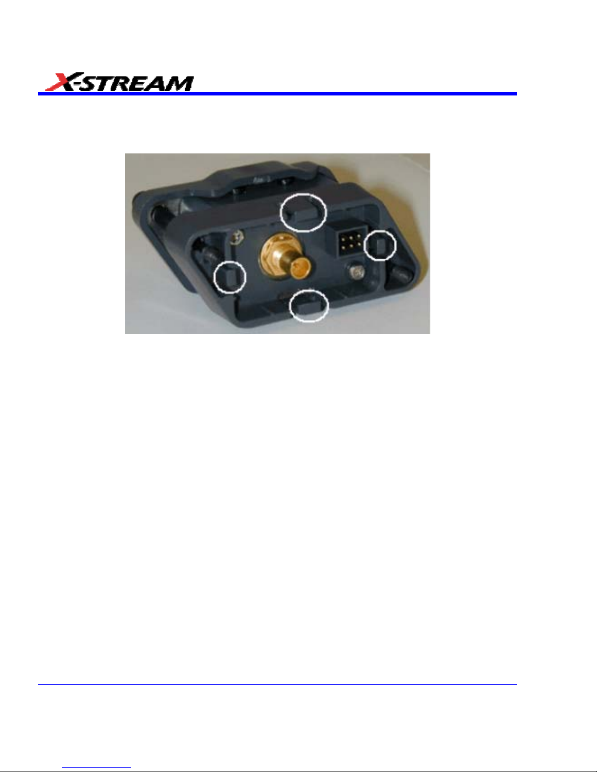
Connecting the Adapters
The mating end of the ProLink adapter has four fastening clips, as shown here:
When installing an adapter on the instrument's connector panel, align the male 6-pin connector
with the female connector and push the adapter straight in. There will be some resistance and
you'll hear clicks as the four clips slide into place. Then tighten the captive screws.
When removing an adapter, loosen the two captive screws. Push down on the adapter to unseat
the clips. This will require some force and will be initially noisy, but no damage will result to the
connector, the floating female BMA connector, or the pins, which can be 15 degrees off axis
when being mated or unmated.
58 SDA-OM-E Rev H
Page 59
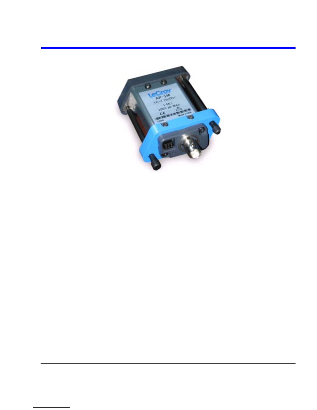
SDA Operator’s Manual
AP-1M Hi-Z Adapter
The AP-1M adapter provides a means to connect a high-impedance input to your instrument. In
order to achieve high bandwidth with excellent signal integrity, these instruments have a ±4 V
dynamic range and 50 termination to ground. However, for applications that combine one or
more high-speed signals with slower, higher-voltage signals, the AP-1M provides a 1 M input
impedance path and a full-scale range of ±8 V. It is also suitable as an interface for current
probes that require a 1 M input path.
In addition to acting as a ProLink-to-ProBus adapter, the AP-1M also enables a much larger
offset voltage range (up to ±50 V).
The AP-1M is supplied with a PP005A passive probe.
SDA-OM-E Rev H 59
Page 60
Auxiliary Output Signals
In addition to a calibration signal, the following signals can be output through the AUX OUTPUT
connector:
Square Wave
Trigger Out - can be used to trigger another scope
DC level - a reference level
Trigger Enabled - can be used as a gating function to trigger another instrument when
the scope is ready
Pass/Fail - allows you to set a pulse duration from 1 ms to 500 ms; generates a pulse
when pass/fail testing is active and conditions are met.
Aux Output Off - turns off the auxiliary output signal
Auxiliary Output Setup
1. In the menu bar, touch Utilities, then Utilities Setup... in the drop-down menu.
2. Touch the Aux Output tab.
3. If you simply want a 1 kHz, 1 V square wave, touch the button so labeled.
4. If you want a specialized output, touch one of the buttons under Use Auxiliary Output For.
5. Touch inside the Amplitude data entry field and enter a value, using the pop-up numeric
keypad. If you want a TTL level signal, touch the TTL Level checkbox. The Amplitude field
will accordingly become unavailable.
6. If you selected Square Wave, touch inside the Frequency data entry field and enter a value,
using the pop-up keypad. You can set a value from 5.0 Hz to 5 MHz.
7. If you selected Pass/Fail, touch inside the Pulse Duration field and enter a value from 1 ms
to 500 ms, using the pop-up numeric keypad.
60 SDA-OM-E Rev H
Page 61
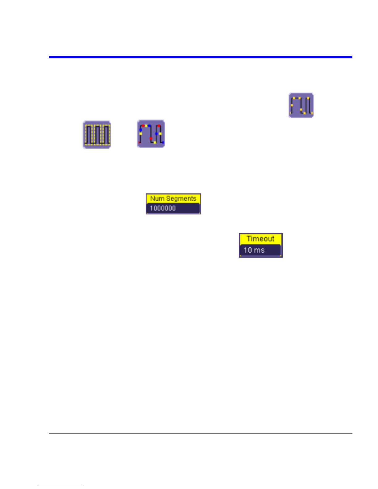
SDA Operator’s Manual
SAMPLING MODES
Sampling Modes
Depending on your timebase, you can choose either Single-shot (Real Time) ,
Sequence
, or RIS mode sampling.
Sampling Mode Selection
1. In the menu bar, touch Timebase, then Horizontal Setup... in the drop-down menu.
2. In the "Horizontal" dialog, touch a Sample Mode button.
3. If you chose Sequence Mode, touch the "Smart Memory" tab, then touch inside the Num
Segments data entry field
and enter a value using the pop-up numeric
keypad.
4. If you want to use a timeout condition for Sequence mode, touch the Enable Timeout
checkbox; then touch inside the Timeout data entry field
and enter a value
using the pop-up numeric keypad.
Single-shot Sampling Mode
Basic Capture Technique
A single-shot acquisition is a series of digitized voltage values sampled on the input signal at a
uniform rate. It is also a series of measured data values associated with a single trigger event.
The acquisition is typically stopped a defined number of samples after this event occurs: a
number determined by the selected trigger delay and measured by the timebase. The waveform's
horizontal position (and waveform display in general) is determined using the trigger event as the
definition of time zero.
You can choose either a pre- or post-trigger delay. Pre-trigger delay is the time from the left-hand
edge of the display grid forward to the trigger event, while post-trigger delay is the time back to
the event. You can sample the waveform in a range starting well before the trigger event up to the
moment the event occurs. This is 100% pre-trigger, and it allows you to see the waveform leading
up to the point at which the trigger condition was met and the trigger occurred. (The instrument
offers up to the maximum record length of points of pre-trigger information.) Post-trigger delay, on
the other hand, allows you to sample the waveform starting at the equivalent of 10,000 divisions
after the event occurred.
SDA-OM-E Rev H 61
Page 62

Because each instrument input channel has a dedicated ADC (Analog-to-Digital Converter), the
voltage on each is sampled and measured at the same instant. This allows very reliable time
measurements between the channels.
On fast timebase settings, the maximum single-shot sampling rate is used. But for slower
timebases, the sampling rate is decreased and the number of data samples maintained.
The relationship between sample rate, memory, and time can be simply defined as:
and
Sequence Sampling Mode Working With Segments
In sequence mode, the complete waveform consists of a number of fixed-size segments acquired
in single-shot mode (see the instrument specifications for the limits). Select the number of
segments to be captured, then select each segment individually and use it for processing with
math and measure tools.
Sequence mode offers a number of unique capabilities. With it, you can limit dead time between
trigger events for consecutive segments. The instrument can capture in fine detail complicated
sequences of events over large time intervals, while ignoring the uninteresting periods between
the events. You can also make time measurements between events on selected segments using
the full precision of the acquisition timebase.
Each individual segment can be zoomed or used as input to math functions.
The instrument uses the sequence timebase setting to determine the capture duration of each
segment: 10 x time/div. Along with this setting, the scope uses the desired number of segments,
maximum segment length, and total available memory to determine the actual number of samples
or segments, and time or points. However, the display of the complete waveform with all its
segments may not entirely fill the screen.
62 SDA-OM-E Rev H
Page 63
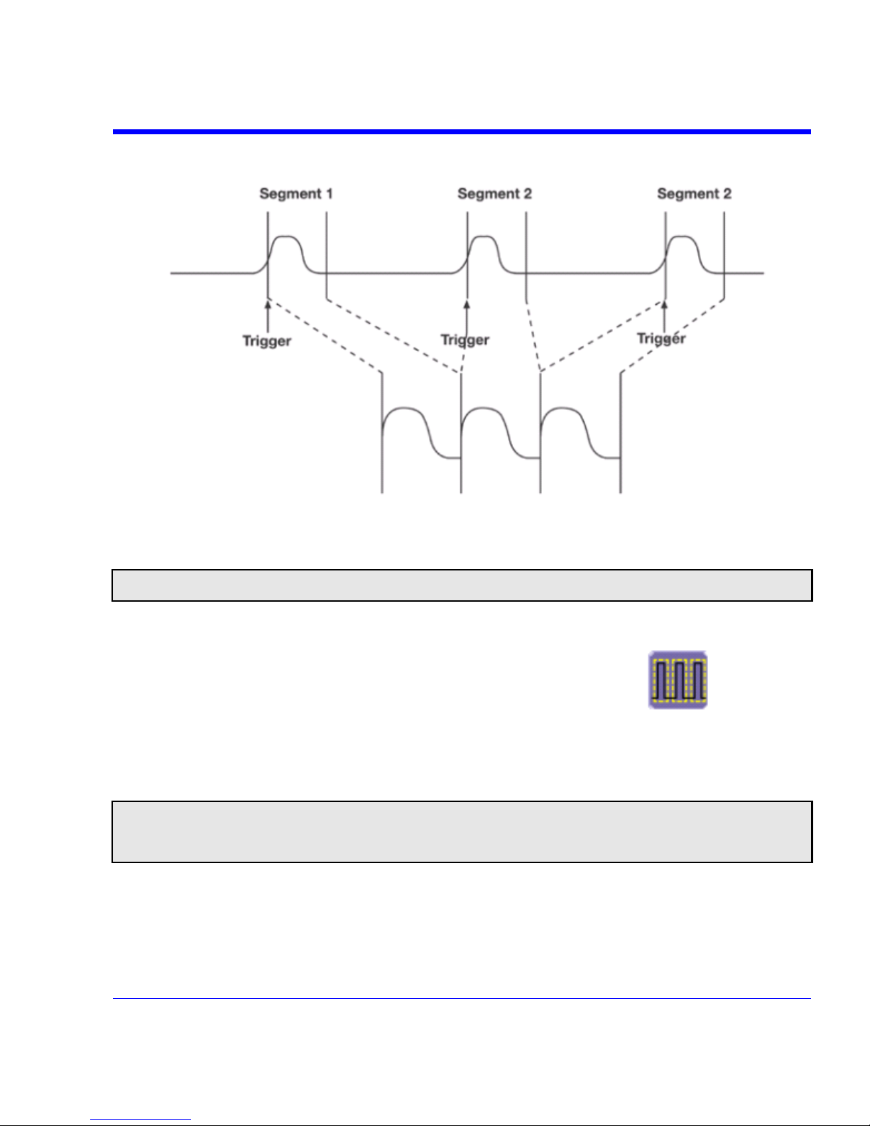
SDA Operator’s Manual
You can also use Sequence mode in remote operation to take full advantage of the instrument's
high data-transfer capability.
How the instrument captures segments
Sequence Mode Setup
Note: Once a single acquisition has started, you can interrupt the acquisition at any time by pressing the Single front
panel button a second time. In this case, the segments already acquired will be retained in memory.
1. In the menu bar, touch Timebase, then touch Horizontal Setup... in the drop-down menu.
2. Touch the Smart Memory tab, then touch the Sequence mode button
.
3. Under Sequence Options, touch inside the Num Segments data entry field and enter the
number of segments you want to display, using the pop-up keypad.
4. Touch inside the Timeout data entry field and enter a timeout value.
Note: The timeout period accounts for instances when a Num Segments miscount occurs for some reason and the
scope waits indefinitely for an unforthcoming segment. During that time, no scope functions are accessible. By means of a
timeout value, however, the acquisition will be completed, the waveform displayed, and control of the scope returned to
the user after the timeout has elapsed.
5. Touch the Enable Timeout checkbox.
6. In the menu bar, touch Display, then Display Setup... in the drop-down menu.
SDA-OM-E Rev H 63
Page 64

7. At the far right of the "Display" dialog, touch inside the Display mode field, and make a
selection from the pop-up menu.
8. Touch inside the Num seg displayed field and enter a value from 1 to 80, using the pop-up
numeric keypad.
9. Touch inside the Starting at field and enter a starting segment number, using the pop-up
numeric keypad.
Sequence Display Modes
The instrument gives you a choice of five ways to display your segments:
Adjacent
Waterfall (cascaded)
Mosaic (tiled)
64 SDA-OM-E Rev H
Page 65

SDA Operator’s Manual
Overlay
Perspective
The number of segments you choose to display (80 maximum) can be less than the total number
of segments in the waveform. For example, in the pop-up images above, the number of display
segments is 10, but the total number of segments entered in the timebase dialog's Num
Segments field is 100.
Displaying Individual Segmen ts
1. Touch Math in the menu bar, then Math Setup... in the drop-down menu.
2. Touch a function tab (F1 to Fx The number of math traces available depends on the software
options loaded on your scope. See specifications.).
3. Touch inside the Operator1 field and select Segment
from the pop-up menu.
4. In the right-hand dialog, touch the Select tab.
5. Touch inside the Select data entry field and use the pop-up numeric keypad to select the
segment you want to display.
Note: In Persistence mode, the segments are automatically overlaid one on top of the other in the display. In nonPersistence mode, they appear separately on the grid.
SDA-OM-E Rev H 65
Page 66

Viewing Time Stamps
1. In the menu bar, touch Timebase, then touch Acquisition Status... in the drop-down menu.
2. Touch the Time tab.
3. Touch one of the channel buttons under Select Waveform.
4. Touch inside the Select Segment field and enter a segment number, using the pop-up
keypad.
RIS SAMPLING Mode - For Higher Sample Rates
RIS (Random Interleaved Sampling) is an acquisition technique that allows effective sampling
rates higher than the maximum single-shot sampling rate. It is used on repetitive waveforms with
a stable trigger. The maximum effective sampling rate of 50 GS/s can be achieved with RIS by
making 100 single-shot acquisitions at 500 MS/s. The bins thus acquired are positioned
approximately 20 ps apart. The process of acquiring these bins and satisfying the time constraint
is a random one. The relative time between ADC sampling instants and the event trigger provides
the necessary variation, measured by the timebase to 5 ps resolution.
The instrument requires multiple triggers to complete an acquisition. The number depends on the
sample rate: the higher the sample rate, the more triggers are required. It then interleaves these
segments (see figure) to provide a waveform covering a time interval that is a multiple of the
maximum single-shot sampling rate. However, the real-time interval over which the instrument
collects the waveform data is much longer, and depends on the trigger rate and the amount of
interleaving required. The oscilloscope is capable of acquiring approximately 40,000 RIS
segments per second.
Note: RIS mode is not available when the scope is operating in Fixed Sample Rate mode. When the SDA 18/13/11/9000
is operating in 18/13/11/9 GHz mode, RIS mode sampling is not available.
66 SDA-OM-E Rev H
Page 67

SDA Operator’s Manual
Roll Mode
Roll mode applies only to WavePro 7000 and WaveRunner 6000 series scopes. It is invoked
automatically when the time per division is 500 ms/div or greater. However, you can cancel Roll
Mode and return to Real Time mode at any time.
Roll mode displays, in real time, incoming points in single-shot acquisitions that have a sufficiently
low data rate. The oscilloscope rolls the incoming data continuously across the screen until a
trigger event is detected and the acquisition is complete. The parameters or math functions
connected to each channel are updated every time the roll mode buffer is updated, as if new data
is available. This resets statistics on every step of Roll mode that is valid because of new data.
Note: If the processing time is greater than the acquire time, the data in memory gets overwritten. In this case, the
instrument issues the warning: Channel data is not continuous in ROLL mode!!! and rolling will start over again.
VERTICAL SETTINGS AND CHANNEL CONTROLS
Adjusting Sensitivity and Position
Adjusting Sensitivity
1. Press the appropriate channel push button, for example
to turn on channel 1. Or
touch Vertical in the menu bar, then Channel 1 in the drop-down menu.
2. Touch inside the Trace On checkbox
to display the trace.
3. Turn the volts per division knob
for the selected channel. Or you can touch inside
the Volts/Div field and type in a value using the pop-up keypad, or use the up/down arrows.
4. The voltage that you set is displayed in the trace descriptor label
and in the
Volts/Div field.
SDA-OM-E Rev H 67
Page 68

Adjusting the Waveform's Position
Turn the vertical offset adjust knob directly above the channel button whose waveform you want
to move vertically.
Or, you can touch inside the Offset field and type in a value on the pop-up keypad. To set the
vertical offset to zero, touch the Zero Offset button directly below the Offset field.
Coupling
The choices of coupling are as follows:
• DC 50 (all instruments)
• GROUND (all instruments)
• DC 1 M (WavePro & WaveRunner instruments)
• AC 1 M (WavePro & WaveRunner instruments)
Overload Protection
The maximum input voltage is 4 V peak. Whenever the voltage exceeds this limit, the coupling
mode automatically switches from DC 50 to GROUND. You will then have to manually reset
the coupling to DC 50 , as described next.
Coupling Setup
1. In the menu bar, touch the Vertical button, then Channel X Setup... in the drop-down menu.
2. Touch inside the Coupling field and select a coupling mode from the pop-up menu.
Probe Attenuation
Setting Probe Attenuation
LeCroy's ProBus system automatically senses probes and sets their attenuation for you. If you
want to set the attenuation manually,
1. In the menu bar, touch Vertical, then select a channel from the drop-down menu.
2. Touch inside the Probe Atten. data entry field
. Touch a divide-by menu
selection or touch Var (variable). If you choose Var, type in a value using the pop-up numeric
keypad.
68 SDA-OM-E Rev H
Page 69

SDA Operator’s Manual
Bandwidth Limit
Reducing the bandwidth also reduces the signal and system noise, and prevents high frequency
aliasing.
To set bandwidth limiting
1. In the menu bar, touch Vertical, then select a channel from the drop-down menu.
2. Touch inside the Bandwidth field and select a bandwidth limit value from the pop-up menu.
The options are
• Full (all X-Stream scopes)
• 4 GHz (WaveMaster 8600A/8500A, DDA-5005A, SDA)
• 3 GHz (WaveMaster 8600A/8500A/4000A/4020, DDA-5005A, SDA)
• 1 GHz (WaveMaster DSOs, DDA-5005A, SDA)
• 200 MHz (all X-Stream scopes)
• 20 MHz (all X-Stream scopes)
Linear and (SinX)/X Interpolation
Linear interpolation, which inserts a straight line between sample points, is best used to
reconstruct straight-edged signals such as square waves. (Sinx)/x interpolation, on the other
hand, is suitable for reconstructing curved or irregular wave shapes, especially when the sample
rate is 3 to 5 times the system bandwidth.
Interpolation Setup
1. Touch the button for the channel you want to set up, for example.
2. In the dialog area, touch inside the Interpolation data entry field under Pre-Processing.
"Pre-Processing" means before Math processing.
3. Touch inside the Interpolation data entry field. A pop-up menu appears offering Linear or
Sinx/x interpolation.
4. Touch the button for the type of interpolation you want.
Inverting Waveforms
Touch the Invert checkbox to invert the waveform for the selected channel.
QuickZoom
QuickZoom automatically displays a zoom of the channel or trace on a new grid.
Turning On a Zoom
Touch the Zoom button
in the channel dialog.
SDA-OM-E Rev H 69
Page 70

70 SDA-OM-E Rev H
Finding Scale
You can access the Find Scale button from the channel setup dialog. This feature automatically
calculates peak-to-peak voltage, and chooses an appropriate Volts/Div scale to fully display the
waveform.
Using Find Scale
1. Touch the trace label for the waveform you desire.
2. Touch the Find Scale icon.
Variable Gain
Variable Gain lets you change the granularity with which the gain is incremented. For example,
when Variable Gain is disabled, the gain will increase or decrease in preset increments of 10 or
100 mV each time you touch the Up/Down buttons.
However, when Variable Gain is enabled, you can increase or decrease the gain in increments
as small as 1 mV, depending on the scale of the waveform.
Enabling Variable Gain
1. Touch the descriptor label for the waveform whose gain you want to vary.
2. Touch the Variable Gain check box.
Channel Deskew
Unlike the Deskew math function, channel Deskew does no resampling, but instead adjusts the
horizontal offset by the amount that you enter. The valid range is dependent on the current
timebase ± 9 divisions.
Channel Deskew Setup
1. In the menu bar, touch Vertical; from the drop-down menu, select a channel to set up.
2. Touch inside the Deskew data entry field and enter a value using the pop-up numeric
keypad.
Page 71

SDA Operator’s Manual
Group Delay Compensation
Group delay is defined as the rate of change of the total phase shift with respect to angular
frequency through a device or transmission medium. An unavoidable consequence of correcting
for group delay is that preshoot and overshoot will be added to the signal.
The SDA 18000/13000/11000/9000 provides a control in the channel "Vertical Adjust" dialog that
allows you to choose between two group delay compensations.
Pulse Response - minimizes preshoot.
This selection is preferred in physics applications: no
"prediction" of the future event.
Eye Diagram - less overshoot.
This selection improves the accuracy of serial eye diagrams.
Flatness – like eye diagram.
This selection provides a flat frequency response.
SDA-OM-E Rev H 71
Page 72

TIMEBASE AND ACQUISITION SYSTEM
Timebase Setup and Control
Set up the timebase by using the front panel Horizontal controls, just as for analog scopes.
For additional timebase setups
1. Touch Timebase in the menu bar, then Horizontal Setup... in the drop-down menu. The
"Horizontal" dialog appears.
2. Touch inside the Time/Division data entry field and enter a value using the pop-up numeric
keypad, or use the up/down arrows to adjust the value.
3. Touch inside the Delay data entry field and type in a value, using the pop-up keypad. Touch
the Set To Zero button to set the delay to zero.
4. Touch the SMART Memory button or tab and adjust the memory as needed.
Autosetup
When channels are turned on, Autosetup operates only on those turned-on channels. If no
channels are turned on, all channels are affected. When more than one channel is turned on, the
first channel in numerical order with a signal applied to it is automatically set up for edge
triggering.
You can perform an autosetup of all these functions together by simply pressing
on the
front panel, or by touching Autosetup
in the Vertical, Timebase, or Trigger
drop-down menu.
SDA DBI Controls
The SDA 18000/13000/11000/9000 oscilloscopes achieve higher bandwidth and sample rate
using an innovative LeCroy technology called Digital Bandwidth Interleaving (DBI). This
technology allows resources to be borrowed from unused channels to multiply not only sample
rate but also bandwidth.
SDA18000 DBI Controls
When 18 GHz is selected, the active channels are either C1 or C4 or
both, providing 60 GS/s sampling on the 18 GHz channel, and 20 GS/s
sampling on the 6 GHz channel.
When 11 GHz is selected, the active channels are C1, C3 and C4. The
11 GHz channel provides 40 GS/s sampling, while the 6 GHz channels
provide 20 GS/s sampling.
When 6 GHz is selected, all 4 channels are active, each providing 20
GS/s.
72 SDA-OM-E Rev H
Page 73

SDA Operator’s Manual
SDA 13000/11000/9000 DBI Controls
When 13/11/9 GHz is selected, the active channels are either C2 or
C3 or both, providing 40 GS/s sampling on each channel. For 6
GHz bandwidth, all four channels can be used, providing 20 GS/s
sampling on each channel. Channels can be set to allow 13/11/9
GHz and 6 GHz bandwidths at the same time, as shown at left.
Smart Memory
Note: When the SDA 18000/13000/11000/9000 is in DBI mode, only Fixed Sample Rate sampling is available.
LeCroy's SMART Memory feature ensures the highest time resolution for the time window
displayed, without aliasing. SMART Memory provides these advantages:
• Acquisition memory is automatically allocated as needed.
• Memory size optimization: Set Maximum Memory optimizes memory to obtain highest
sampling rate, reducing the risk of aliasing. You can set a maximum memory up to 48 Mpts.
• Fixed Sample Rate allows setting of a specific sample rate, with the scope calculating the
amount of memory needed for a timebase setting.
• The entire acquisition is displayed on the screen.
• High-speed compaction shows all significant features of your waveform.
• You can set a maximum memory up to 48 Mpts.
SDA-OM-E Rev H 73
Page 74

74 SDA-OM-E Rev H
SMART Memory Setup
1. Touch Timebase in the menu bar, then SMART Mem Setup... in the drop-down menu.
2. Touch the SMART Memory tab.
3. Under Timebase Mode, touch the Set Maximum Memory or Fixed Sample Rate button.
Information about your choice appears below the buttons. The calculated memory length and
time per sample point appear below the scroll buttons.
4. Touch inside the Time/Division data entry field and set a time per division.
Note: If you are currently acquiring waveforms, you will notice a change in sampling rate as you select different modes.
5. If you selected Sequence mode, touch inside the Num Segments data entry field and enter
a value using the pop-up numeric keypad. If you want to use a timeout period, touch the
Enable Timeout checkbox; then touch inside the Timeout data entry field and enter a value.
External Timebase vs. External Clock
An external timebase reference is used to synchronize the scope's internal timebase to an
external frequency source. This allows multiple instruments to lock their timebases to a common
source. The external timebase reference frequencies are model dependent. For example, the
WaveMaster, SDA, and DDA series instruments use 100 MHz ±0.001%, and the voltage level
required is 650 mV
pk-pk
or 0.0 dBm ±30%. On the other hand, the WavePro 7000A series uses an
external timebase reference of 10 MHz ±0.01% with an amplitude of 650 mV
pk-pk
or 0.0 dBm
±30%. The external timebase reference is applied to the rear panel BNC connector.
Note: An external timebase reference cannot be applied to the SDA 18000/13000/11000/9000 when operating in DBI
mode.
An external sampling clock, applied via the auxiliary input, replaces the scope's internal timebase
as the sampling clock. This means that the external sampling clock controls when the scope's
digitizers sample the input waveforms. The frequency range of the external sampling clock is
model dependent: WaveMaster, SDA, DDA, and WavePro 7000A series scopes require a signal
frequency between 30 MHz and 2 GHz. However, the WaveRunner 6000A series scopes accept
an external sampling clock between DC and 1 GHz. In all cases, the external sampling clock
levels are TTL, ECL, or 0 volt crossing 650 mV
pk-pk
or 0.0 dBm ±30%. Since the external
sampling clock uses the auxiliary input, an external trigger cannot be used when the external
sampling clock is in use.
TRIGGERING
TRIGGER SETUP CONSIDERATIONS
Trigger Modes
Auto mode causes the scope to sweep even without a trigger. An internal timer triggers the
sweep so that the display remains, even when the signal does not cause a trigger.
Page 75
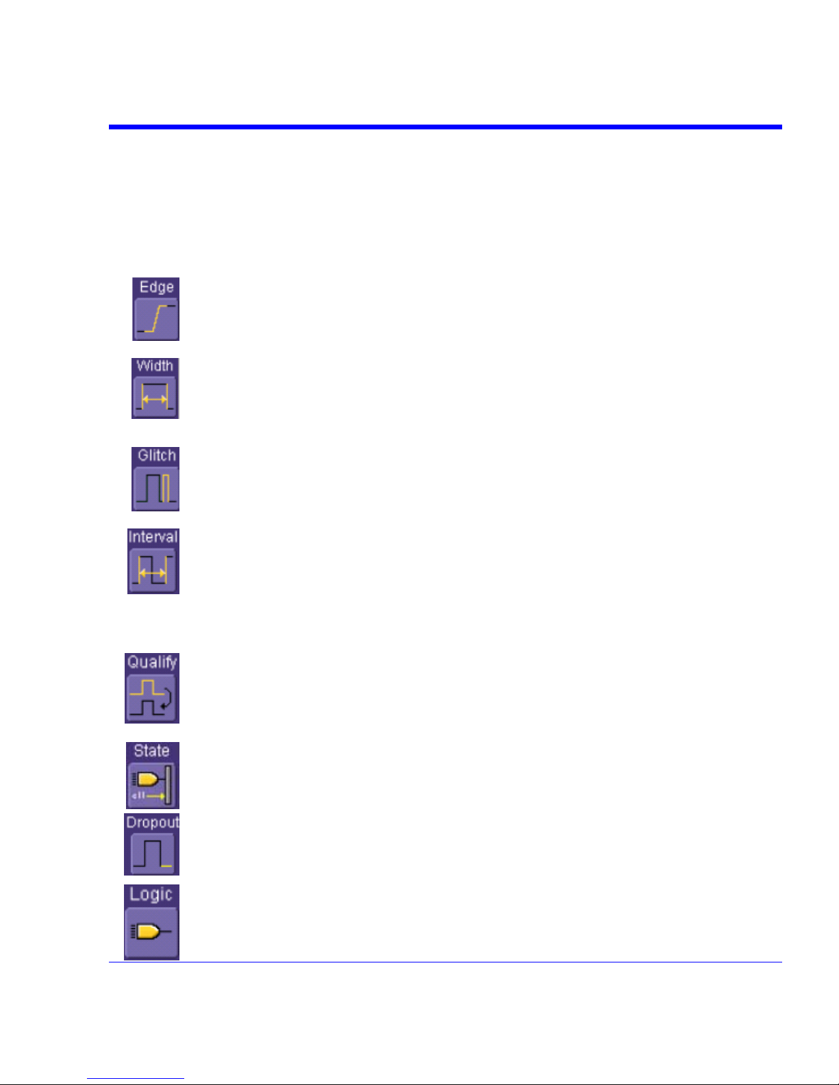
SDA Operator’s Manual
In Normal mode, the scope sweeps only if the input signal reaches the set trigger point.
Otherwise it continues to display the last acquired waveform.
In Single mode, only one sweep occurs each time you press the button.
Stop mode inhibits all sweeps until you select one of the other three modes.
Trigger Types
The triggers available to you are defined as follows:
SDA-OM-E Rev H 75
A simple trigger, Edge trigger is activated by basic waveform features or conditions
such as positive or negative slope, and holdoff.
One of LeCroy's SMART Triggers®, Width trigger allows you to define a positive- or
negative-going pulse width bounded by a voltage level, above or below which a trigger
will occur. Or you can specify a pulse width and voltage range, within or outside of
which a trigger will occur.
Another of the SMART Triggers, Glitch trigger is a simpler form of Width trigger. Use
Glitch trigger when you want to define a fixed pulse-width time or time range only.
Glitch trigger makes no provision for voltage levels or ranges.
While Glitch trigger performs over the width of a pulse, Interval trigger performs over
the width of an interval the signal duration (the period) separating two consecutive
edges of the same polarity: positive to positive or negative to negative. Use interval
trigger to capture intervals that fall short of, or exceed, a given time limit. In addition,
you can define a width range to capture any interval that is itself inside or outside the
specified range an Exclusion trigger by interval.
The Qualify trigger is an edge-qualified SMART Trigger that allows you to use one
signal's positive or negative transition to qualify a second signal, which is the trigger
source. For Qualify trigger, you specify the time or number of events after the transition
when you want the trigger to occur.
The State trigger is a level-qualified SMART Trigger which requires that the qualifying
signal remain above or below a specified voltage level for a trigger to occur. For Sate
trigger, you specify the time or number of events after the signal has gone above or
below the voltage level when you want the trigger to occur.
Used primarily in single-shot applications, and usually with a pre-trigger delay, Dropout
trigger can detect lost signals. The trigger is generated at the end of the timeout period
following the last trigger source transition. You can select a timeout period from 2 ns to
20 s.
Logic trigger enables triggering on a logical combination (pattern) of five inputs: CH1,
CH2, CH3, CH4, EXT. You have a choice of four Boolean operators (AND, NAND, OR,
NOR), and you can stipulate the high or low voltage logic level for each input
independently.
Page 76

Determining Trigger Level, Slope, Source, and Coupling
Level defines the source voltage at which the trigger circuit will generate an event: a change in
the input signal that satisfies the trigger conditions. The selected trigger level is associated with
the chosen trigger source.
Trigger level is specified in volts and normally remains unchanged when you change the vertical
gain or offset. The amplitude and range of the trigger level are limited as follows:
• ±4.1 screen divisions with a channel as the trigger source
• ±400 mV with EXT as the trigger source
• ±4 V with EXT/10 as the trigger source
• ±40 mV with EXT*10 as the trigger source
• None with LINE as the trigger source (zero crossing is used).
Coupling refers to the type of signal coupling at the input of the trigger circuit. Because of the
instrument's very high bandwidth, there is only one choice of trigger coupling: DC 50 . However,
as a visual check of where ground is, you may switch the channel to ground coupling at any time
while testing.
With DC coupling, all of the signal's frequency components are coupled to the trigger circuit for
high-frequency bursts.
Slope determines the direction of the trigger voltage transition used for generating a particular
trigger event. You can choose a positive or negative slope. Like coupling, the selected slope is
associated with the chosen trigger source.
Edge trigger works on the selected edge at the chosen level. The slope (positive or negative) is specified in the
Trigger label permanently displayed below-right of the grid.
76 SDA-OM-E Rev H
Page 77

SDA Operator’s Manual
SDA-OM-E Rev H 77
Trigger Source
The Trigger On source may be one of the following:
• The acquisition channel signal (CH 1, CH 2, CH 3 or CH 4) conditioned for the overall voltage
gain, coupling, and bandwidth.
• The line voltage that powers the oscilloscope (LINE). This can be used to provide a stable
display of signals synchronous with the power line. Coupling and level are not relevant for
this selection.
• The signal applied to the EXT BNC connector (EXT). This can be used to trigger the
oscilloscope within a range of ±400 mV on EXT, ±4 V with EXT/10 as the trigger source, or
±40 mV with EXT*10 as the trigger source.
• A logic pattern.
Level
Level defines the source voltage at which the trigger circuit will generate an event (a change in
the input signal that satisfies the trigger conditions). The selected trigger level is associated with
the chosen trigger source. Note that the trigger level is specified in volts and normally remains
unchanged when the vertical gain or offset is modified.
The Amplitude and Range of the trigger level are limited as follows:
• ±4.1 screen divisions with a channel as the trigger source
• ±400 mV with EXT as the trigger source
• ±4 V with EXT/10 as the trigger source
• ±40 mV with EXT*10 as the trigger source
• none with LINE as the trigger source (zero crossing is used)
Note: Once specified, Trigger Level and Coupling are the only parameters that pass unchanged from trigger mode to
trigger mode for each trigger source.
Holdoff by Time or Events
Holdoff is an additional condition of Edge trigger. It can be expressed either as a period of time or
an event count. Holdoff disables the trigger circuit for a given period of time or number of events
after the last trigger occurred. Events are the number of occasions on which the trigger condition
is met. The trigger will again occur when the holdoff has elapsed and the trigger's other
conditions are met.
Use holdoff to obtain a stable trigger for repetitive, composite waveforms. For example, if the
number or duration of sub-signals is known you can disable them by choosing an appropriate
holdoff value. Qualified triggers operate using conditions similar to holdoff.
Page 78
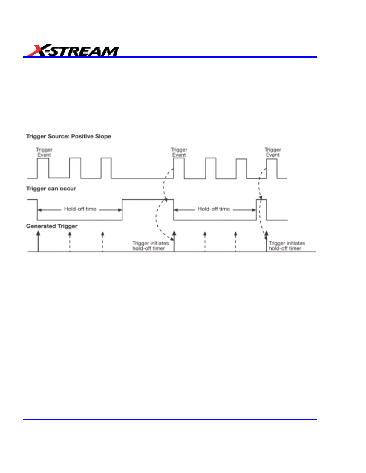
Hold Off by Time
Sometimes you can achieve a stable display of complex, repetitive waveforms by placing a
condition on the time between each successive trigger event. This time would otherwise be
limited only by the input signal, the coupling, and the instrument's bandwidth. Select a positive or
negative slope, and a minimum time between triggers. The trigger is generated when the
condition is met after the selected holdoff time, counted from the last trigger. Any time between 2
ns and 20 s can be selected. The delay is initialized and started on each trigger.
Edge Trigger with Holdoff by Time. The bold edges on the trigger source indicate that a positive slope has been
selected. The broken upward-pointing arrows indicate potential triggers, which would occur if other conditions
are met. The bold arrows indicate where the triggers actually occur when the holdoff time has been exceeded.
78 SDA-OM-E Rev H
Page 79
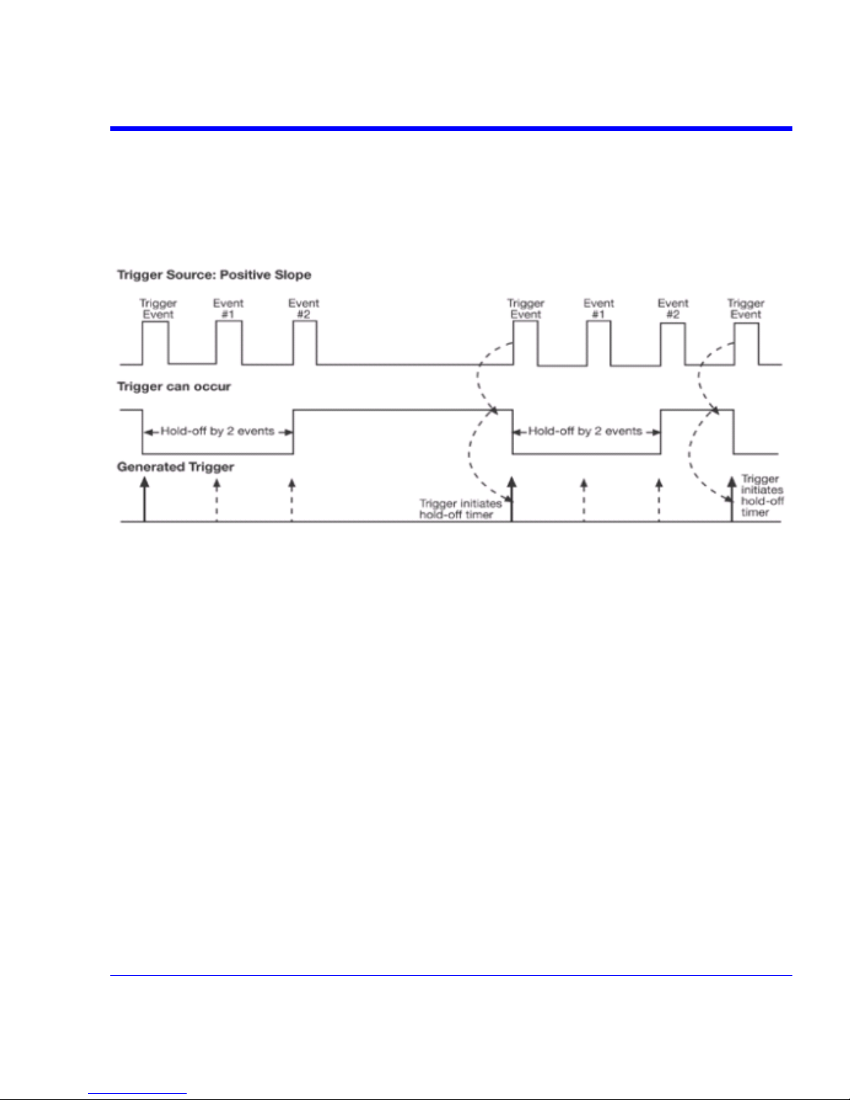
SDA Operator’s Manual
Hold Off by Events
Select a positive or negative slope and a number of events. An event is the number of times the
trigger condition is met after the last trigger. A trigger is generated when the condition is met after
this number, counted from the last trigger. The count is restarted on each trigger. For example, if
the event number is two, the trigger will occur on the third event. From one to 1,000,000,000
events can be selected.
Edge Trigger with Holdoff by Events (in this example, two events). The bold edges on the trigger source indicate
that a positive slope has been selected. The broken, u pward-pointing arrows indicate potential triggers, while the
bold ones show where triggers actually occur after the holdoff expires.
Simple Triggers
Edge Trigger on Simple Signals
The instrument uses many waveform capture techniques that trigger on features and conditions
that you define. These triggers fall into two major categories:
• Edge activated by basic waveform features or conditions such as a positive or negative
slope, and hold-off
• SMART Trigger® sophisticated triggers that enable you to use basic or complex conditions
for triggering.
Use Edge Triggers for simple signals, and the SMART Triggers for signals with rare features, like
glitches.
SDA-OM-E Rev H 79
Page 80
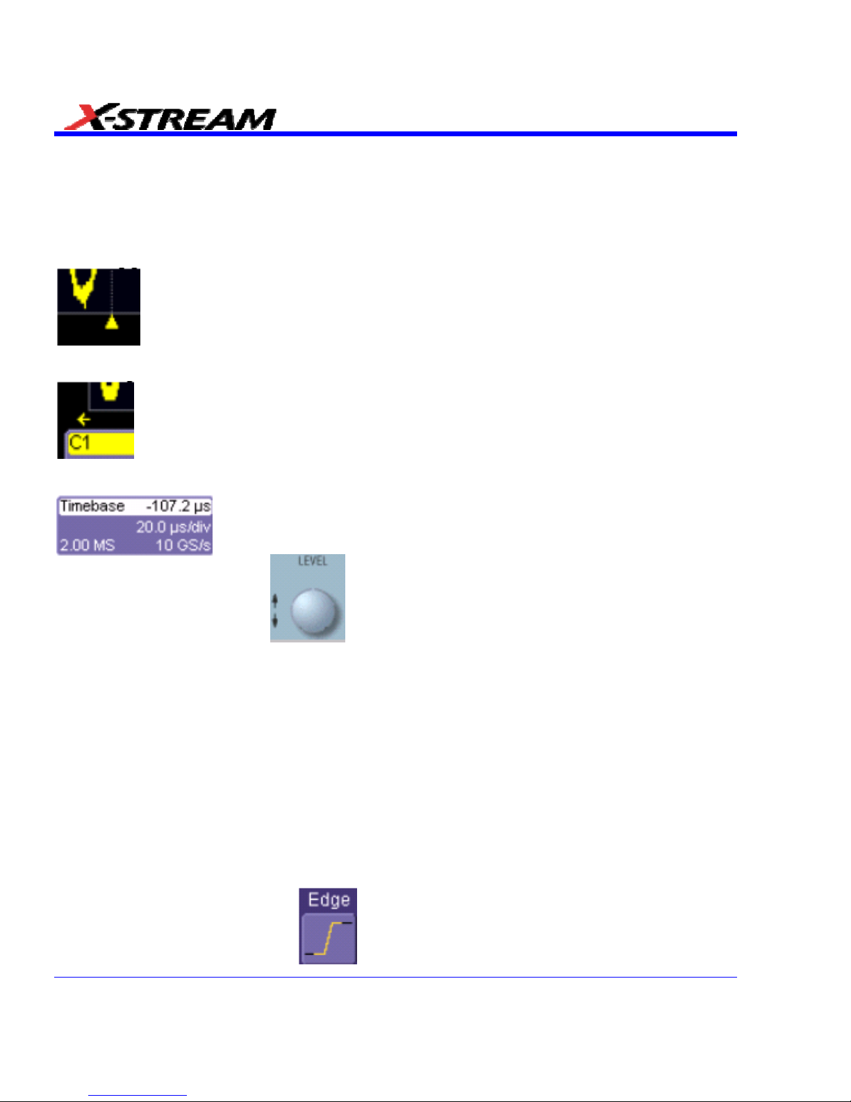
Control Edge Triggering
Horizontal: Turn the Delay knob in the HORIZONTAL control group to adjust the trigger's
horizontal position. Or, touch inside the Delay field in the timebase setup dialog and enter a
value, using the pop-up keypad.
The trigger location is shown by a marker under the grid:
Post-trigger delay is indicated by a left-pointing arrow below-left of the grid:
The time value is given in the title line of the TimeBase label below-right of the grid:
Vertical: Turn the L
EVEL knob in the TRIGGER control group to adjust the trigger's
vertical threshold.
Turn this knob to adjust the level of the trigger source or the highlighted trace. Level defines the
source voltage at which the trigger will generate an event a change in the input signal that
satisfies the trigger conditions.
Alternatively, in the "Trigger" dialog, you can touch inside the Level field and type in a value,
using the pop-up numeric keypad. To quickly set a level of zero volts, touch the Zero Level
button directly below the Coupling field.
An arrow on the left side of the grid shows the threshold position. This arrow is only visible if the
trigger source is displayed.
Edge Trigger Setup
Channel Setup
1. In the menu bar, touch Trigger, and then select Trigger Setup... from the drop-down menu.
2. Touch the Edge trigger button
under the Trigger tab.
80 SDA-OM-E Rev H
Page 81

SDA Operator’s Manual
3. Touch inside the Trigger On data entry field and select an input from the pop-up menu:
4. Touch inside the Level data entry field
. In the pop-up numeric keypad,
enter a value in millivolts or use the up/down buttons
to increase or decrease the
value in increments of 1 mV. Or, touch one of the preset value buttons:
Max.
1.000 V
Default
0 mV
Min.
1.000 V
5. Select the holdoff by touching the Time or Events buttons . Using the pop-up
numeric keypad, enter a value and specify the unit of time:
SDA-OM-E Rev H 81
Page 82

• Or, use the up/down buttons to increase or decrease the time value in
increments of 200 ps. Or, touch one of the preset value buttons:
The preset Time values are as follows:
Max.
20.0 s
Default
50.0 ns
Min.
2 ns
The preset Events values are as follows:
Max.
1,000,000,000
events
Default
1 event
Min.
1 event
6. Choose Positive or Negative slope
82 SDA-OM-E Rev H
Page 83

SDA Operator’s Manual
SMART Triggers
Width Trigger
How Width Trigger Works
Width trigger allows you to define a positive- or negative-going pulse width bounded by a voltage
level, above or below which a trigger will occur. You can specify a pulse width and voltage range,
within or outside of which a trigger will occur.
Width Trigger Setup
1. In the menu bar, touch Trigger, then Trigger Setup... in the drop-down menu.
2. Touch the Width trigger button
3. Touch inside the Trigger On data entry field and select a source on which to trigger:
4. Touch inside the Level data entry field and enter a value using the pop-up numeric keypad.
5. Select positive or negative slope.
6. Touch the LessThan button and enter a pulse-width value in the Upper Limit data entry
field. Or touch the GreaterThan button and enter a pulse-width value in the Lower Limit data
entry field. Or touch the InRange button. Touch the Delta button
to set up a nominal
range, plus or minus a delta value in seconds. Touch inside the Nominal Width and Delta
data entry fields and enter values using the pop-up numeric keypads. Alternately, touch the
Limits button
to set up a precise pulse-width range. Touch inside the Lower Limit
and Upper Limit data entry fields and enter values using the pop-up keypads. Or touch the
OutOfRange button and perform the same range setups as for InRange triggering.
SDA-OM-E Rev H 83
Page 84

Glitch Trigger
How Glitch Trigger Works
Glitch trigger can be used to catch glitches. You can specify a pulse width or a pulse width range.
Pulse smaller than selected pulse width: Set a maximum pulse width. This glitch trigger is
generated on the selected edge (positive or negative) when the pulse width is less than or equal
to the set width.
The timing for the width is initialized and restarted on the opposite slope to that selected. You can
set widths from 600 ps to 20 s.
Note: If the glitch's width is narrower than the signal's width, set the trigger to a narrower width than that of the signal. The
signal's width, as determined by the instrument trigger comparator, depends on the DC trigger level. If that level were to
be set at the middle of a sine wave, for example, the width could then be considered as the half period. But if the level
were higher, the signal's width would be considered to be less than the half period.
Glitch Trigger: In this example triggering on a pulse width less than or equal to the width selected. The broken
upward-pointing arrow indicates a potential trigger, while the bold one shows where the actual trigger occurs.
84 SDA-OM-E Rev H
Page 85

SDA Operator’s Manual
Glitch Trigger Setup
1. In the menu bar, touch Trigger, then Trigger Setup... in the drop-down menu.
2. Touch the Glitch trigger button
.
3. Touch inside the Trigger On data entry field and select a source on which to trigger.
4. Touch inside the Level data entry field and enter a value using the pop-up numeric keypad.
5. Select positive or negative slope.
6. Define the width of the glitch you are looking for. You can trigger on any glitch less than a
chosen pulse-width (Upper Limit); or you can trigger on a chosen range (InRange). Touch
the LessThan button; the Upper Limit data entry field alone is displayed. Touch the
InRange button; the Upper Limit and Lower Limit fields are displayed.
7. Touch inside the limit field or fields and enter a time value using the pop-up numeric keypad.
Interval Trigger
How Interval Triggers Work
While Glitch trigger performs over the width of a pulse, Interval trigger performs over the width of
an interval, with the signal duration (period) separating two consecutive edges of the same
polarity: positive to positive or negative to negative. Use Interval trigger to capture intervals that
fall short of, or exceed, a given time limit. In addition, you can define a width range to capture any
interval that is itself inside or outside the specified range: an exclusion trigger by interval.
Interval Less Than: For this Interval Trigger, generated on a time interval smaller than the one
that you set, choose a maximum interval between two like edges of the same slope (positive, for
example).
The trigger is generated on the second (positive) edge if it occurs within the set interval. The
instrument initializes and restarts the timing for the interval whenever the selected edge occurs.
You can set an interval from 2 ns to 20 s.
SDA-OM-E Rev H 85
Page 86

Interval Trigger that triggers when the interval width is smaller than the selected interval. The broken, upward-
pointing arrow indicates a potential trigger, while the bold one shows where the actual trigger occurs on the
positive edge within the selected interval.
Interval Greater Than: For this Interval Trigger, generated on an interval larger than the one that
you set, select a minimum interval between two edges of the same slope. The instrument
generates the trigger on the second edge if it occurs after the set interval. The timing for the
interval is initialized and restarted whenever the selected edge occurs. You can set an interval
from 2 ns to 20 s.
86 SDA-OM-E Rev H
Page 87

SDA Operator’s Manual
Interval Trigger that triggers when the interval width is larger than the set interval. The broken upward-pointing
arrow indicates a potential trigger, while the bold one shows where the actual trigger occurs on the positive edge
after the selected interval.
Interval In Range: This Interval Trigger is generated whenever an interval between two edges of
the same slope falls within a selected range. The instrument initializes and restarts the timing for
the interval whenever the selected edge occurs. You can set an interval from 2 ns to 20 s.
SDA-OM-E Rev H 87
Page 88
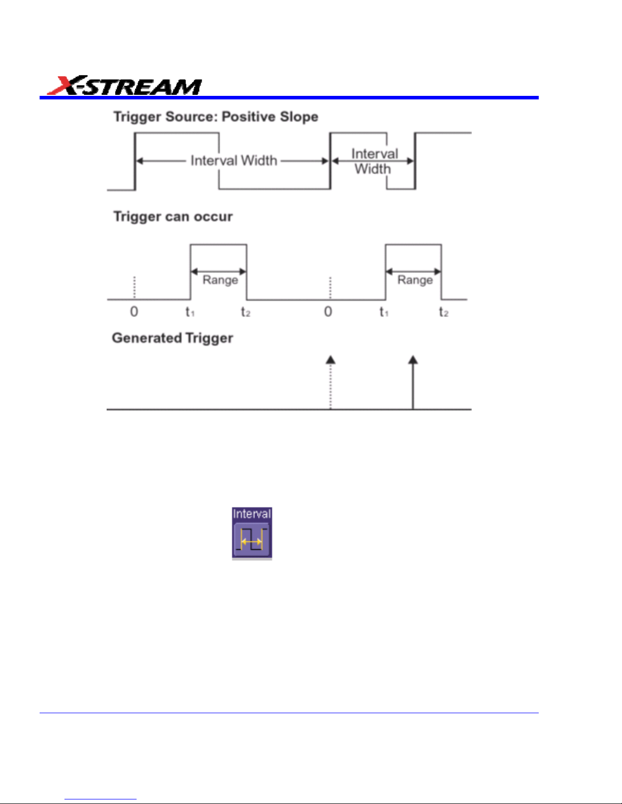
Interval Trigger that triggers when the interval falls within the selected range:
t1 = range's lower time limit; t2 = range's upper limit. The broken upward-pointing arrow indicates a potential
trigger, while the bold one indicates where the actual trigger occurs on the positive edge within the selected
range.
Interval Trigger Setup
1. In the menu bar, touch Trigger, then Trigger Setup... in the drop-down menu.
2. Touch the Interval trigger button
.
3. Touch inside the Trigger On data entry field and select a source on which to trigger.
Touch inside the Level data entry field and enter a value using the pop-up numeric keypad.
4. Select positive or negative slope.
5. Touch the LessThan button and enter a pulse-width value in the Upper Limit data entry
field.
Or touch the GreaterThan button and enter a value in the Lower Limit data entry field.
Or touch the InRange button.
88 SDA-OM-E Rev H
Page 89

SDA Operator’s Manual
6. Touch the Delta button to set up a nominal range, plus or minus a delta value in
seconds. Touch inside the Nominal Width and Delta data entry fields and enter values using
the pop-up numeric keypads.
7. Touch the Limits button
to set up a precise range. Touch inside the Lower Limit and
Upper Limit data entry fields and enter values using the pop-up numeric keypads.
Or touch the OutOfRange button and perform the same Delta or Limits setup as for
InRange triggering.
Qualified Trigger
How Qualified Triggers Work
Use a signals transition above or below a given level (its validation) as an enabling (qualifying)
condition for a second signal that is the trigger source. These are Qualified triggers. For Edge
Qualified triggers (the default) the transition is sufficient and no additional requirement is placed
on the first signal. For State Qualified triggers the amplitude of the first signal must remain in the
desired state until the trigger occurs. A qualified trigger can occur immediately after the validation,
or following a predetermined time delay or number of potential trigger events. The time delay or
trigger count is restarted with every validation.
Within Time creates a time window within which a trigger can occur.
Wait Time determines a delay from the start of the desired pattern. After the delay
(timeout) and while the pattern is present, a trigger can occur. The timing for the delay is restarted
when the selected pattern begins.
Events determines a minimum number of events of the trigger source. An event is
generated when a trigger source meets its trigger conditions. On the selected event of the trigger
source and while the pattern is present, a trigger can occur. The count is initialized and started
whenever the selected pattern begins, and continues while the pattern remains. When the
selected count is reached, the trigger occurs.
SDA-OM-E Rev H 89
Page 90
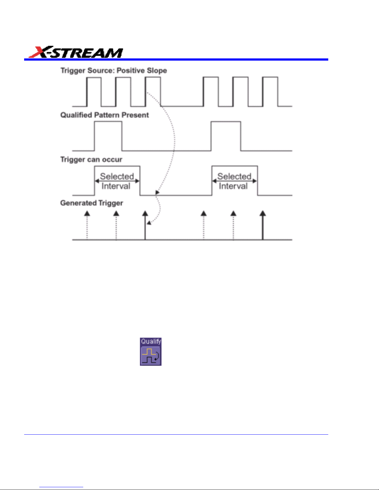
Edge Qualified and Wait: Trigger after timeout. The broken upward-pointing arrows indicate potential triggers,
while the bold ones show where the actual triggers occur.
Qualified First Trigger
Qualified First trigger is intended to be used exclusively in Sequence Mode to speed up the
trigger rate. With Qualified First trigger, a single valid trigger is sufficient to acquire a full
sequence. Other than in Sequence Mode, Qualified First is identical to the Qualified triggers.
In data storage applications, the index pulse can be defined as the qualifier signal and the servo
gate signal as the trigger source.
Edge Qualified Trigger Setup
1. In the menu bar, touch Trigger, then Trigger Setup... in the drop-down menu.
2. Touch the Qualify trigger button
.
3. Touch inside the Trigger On data entry field and select a source on which to trigger.
Select Positive or Negative slope.
90 SDA-OM-E Rev H
Page 91

SDA Operator’s Manual
4. Touch inside the After data entry field and select the qualifying signal source from the pop-up
menu. If you select an input channel or external source, touch inside the has gone data entry
field and select a logic level: Above or Below. Then touch inside the Level field and set a
voltage level using the pop-up numeric keypad. If you select Pattern from the pop-up menu,
touch the Pattern tab and choose a logic gate. Then touch inside the State field for each
channel input you want to use in the pattern and select a logic condition: High or Low. Select
Don't Care for unused inputs. For the inputs to be used, touch inside each Level field and
enter a voltage threshold using the pop-up numeric keypad. Then touch the Trigger tab
again.
5. If you want to set a holdoff in time or events, touch one of the Qualify by: buttons:
6. Touch inside the field below the Qualify by: buttons and enter a value using the numeric
keypad.
7. To set up a Qualified First trigger, touch the Qualify first segment only checkbox if you are
in Sequence mode.
State Trigger
State trigger is another Qualified trigger; however, instead of using the edges of the qualifying
inputs, State trigger uses the logic state of the inputs to qualify the trigger. Therefore, the pattern
must become true and remain true (for a period of time or number of events that you specify) to
qualify the trigger.
See also the How Qualified Triggers Work topic (previous).
State Qualified and Wait: Trigger after timeout. The broken upward-pointing arrows indicate potential triggers,
while the bold arrows show where the actual triggers occur.
SDA-OM-E Rev H 91
Page 92
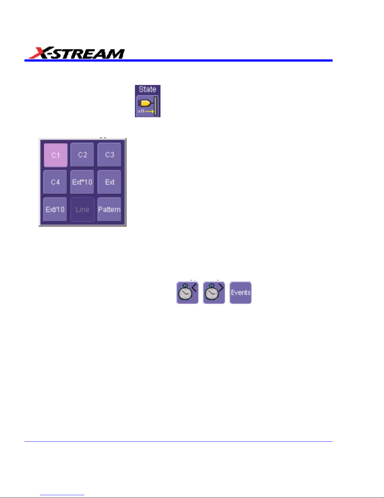
State Qualified Trigger Setup
1. In the menu bar, touch Trigger, then Trigger Setup... in the drop-down menu.
2. Touch the State trigger button
.
3. Touch inside the Trigger On data entry field and select a source on which to trigger:
4. Select Positive or Negative slope.
5. Touch inside the has gone data entry field and select the qualifying signal source from the
pop-up menu. If you select an input channel or external source, touch inside the has gone
data entry field and select a logic level: Above or Below. Then touch inside the Level field
and set a voltage level using the pop-up numeric keypad. If you want to set a holdoff in time
or events, touch one of the holdoff buttons:
6. Touch inside the field below the holdoff buttons and set a value using the numeric keypad.
Dropout Trigger
Used primarily in single-shot applications, and usually with a pre-trigger delay, Dropout trigger
can detect lost signals. The trigger is generated at the end of the timeout period following the last
trigger source transition. You can set a timeout period from 2 ns to 20 s.
92 SDA-OM-E Rev H
Page 93
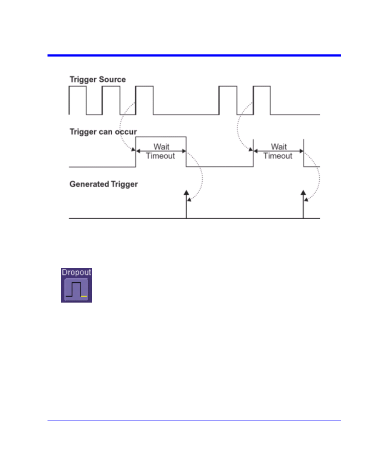
SDA Operator’s Manual
How Dropout Trigger Works
Dropout Trigger: occurs when the timeout has expired. The bold upward-pointing arrows show where the trigger
occurs.
Dropout Trigger Setup
1. In the menu bar, touch Trigger, then Trigger Setup... in the drop-down menu.
2. Touch the Dropout trigger button.
3. Select Positive or Negative slope.
4. Touch inside the Trigger after timeout data entry field and enter a time window using the
pop-up numeric keypad.
SDA-OM-E Rev H 93
Page 94
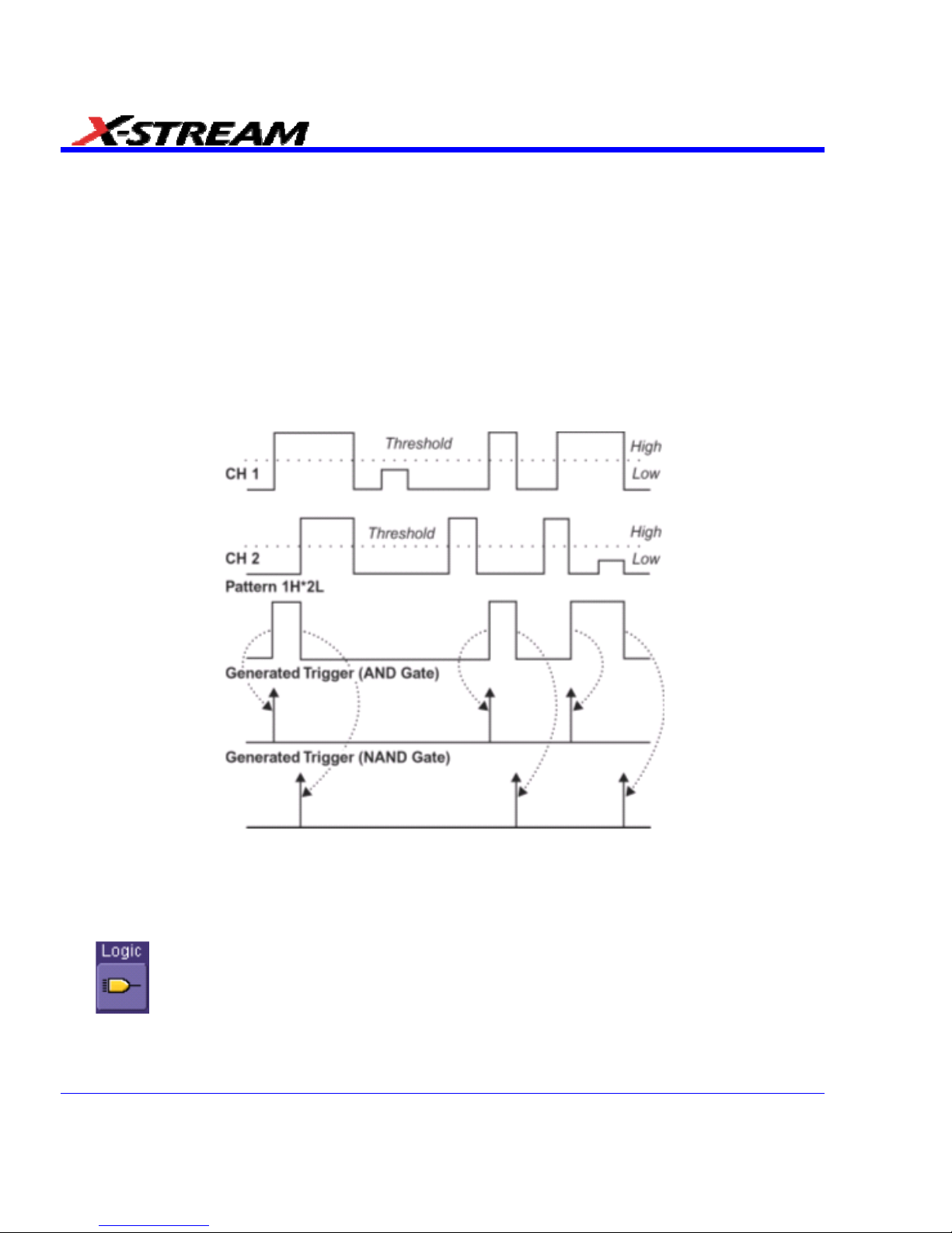
Logic Trigger
How Logic Trigger Works
Logic Trigger enables triggering on a logical combination of up to five inputs: CH 1, CH 2, CH 3,
CH 4, and EXT. The combination of inputs is referred to as a pattern. There are four logic gates
available: AND, NAND, OR, NOR.
A trigger state is either high or low: high when a trigger source is greater than the trigger level
(threshold) and low when less than it. For example, an AND pattern could be defined as true
when the trigger state for CH 1 is high, CH 2 is low, and EXT is irrelevant (X or don't care). If any
one of these conditions is not met, the pattern state is considered false. You can set holdoff limits
from 2 ns to 20 s or from 1 to 1,000,000,000 events.
Logic Applications
Logic Trigger can be used in digital design for the testing of complex logic inputs or data transmission buses.
Logic Trigger Setup
1. In the menu bar, touch Trigger, then Trigger Setup... in the drop-down menu.
2. Touch the Logic trigger button.
3. Touch the Pattern tab.
4. For each input you want to include in the logic pattern, touch inside the State data entry field
and select a logic state: Low or High. Select Don't Care for all other inputs.
94 SDA-OM-E Rev H
Page 95
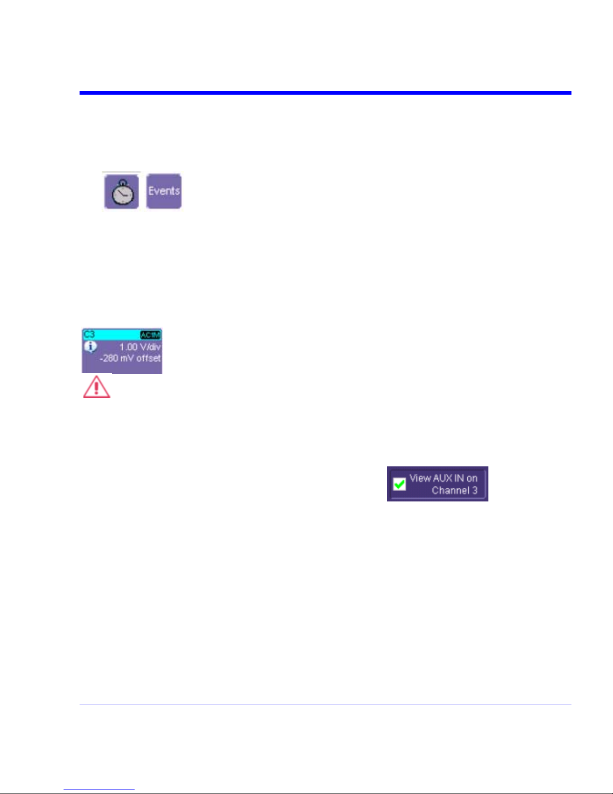
SDA Operator’s Manual
5. Touch inside the Level data entry field for each input included in the pattern and enter a
voltage level threshold using the pop-up numeric keypad.
6. Touch the Trigger tab.
7. If you want to hold off the trigger (either in time or events) when the pattern becomes true,
touch one of the holdoff buttons:
8. Touch inside the holdoff data entry field and enter a value using the pop-up numeric keypad.
Serial Trigger
Serial Trigger is only available on SDA “A” model scopes.
Aux Input Trigger
Some instrument models give you the capability to trigger on an auxiliary input. When you select
this option, the auxiliary trigger setup is routed to channel 3, and an information icon appears in
the Channel 3 descriptor label.
CAUTION
If you select Aux Input trigger on a WavePro 7000 Series scope, but do not input an
external signal, the scope will not operate.
Aux Input Setup
1. Touch Trigger in the menu bar, then Trigger Setup... in the drop-down menu.
2. Touch inside the View AUX IN on Channel 3 check-box
. The Coupling
field is then disabled.
3. Press the Channel 3 front panel button to turn on Channel 3 and display the setup dialog.
4. Perform vertical setups for your auxiliary input in the Channel 3 dialog.
SDA-OM-E Rev H 95
Page 96

5. Touch Vertical in the menu bar, then Channels Status... in the drop-down menu to view a
summary of the Aux Input setup:
DISPLAY FORMATS
Display Setup
1. In the menu bar, touch Display; then touch Display Setup in the drop-down menu.
2. Touch one of the Grid combination buttons:
As selections are made, Autogrid automatically shows or removes grids from the scope
display.
3. Touch inside the grid Intensity data entry field and enter a value from 0 to 100 using the pop-
up keypad.
4. Touch the Grid on top checkbox if you want to superimpose the grid over the waveform.
Depending on the grid intensity, some of your waveform may be hidden from view when the
grid is placed on top. To undo, simply uncheck Grid on top.
5. Touch the Axis labels checkbox to permanently display the values of the top and bottom grid
lines (calculated from volts/div) and the extreme left and right grid lines (calculated from the
timebase).
96 SDA-OM-E Rev H
Page 97

SDA Operator’s Manual
6. Choose a line style for your trace: solid Line or Points .
Sequence Mode Display
To a set up Sequence Mode display, you must first have selected Sequence trigger mode in the
Timebase "Horizontal" dialog. You must also have entered a Num Segments value.
1. In the menu bar, touch Display; then touch Display Setup in the drop-down menu.
2. Touch inside the Display Mode field and select a display mode from the pop-up menu.
3. Touch inside the Num seg displayed field and enter a value, using the pop-up keypad. The
maximum number of segments that can be displayed is 80.
4. Touch inside the Starting at field and enter a value.
Note: The maximum value that you can enter for Starting at depends on the Num Segments value you entered in the
"Timebase" dialog. It also depends on the Num seg displayed value you entered here in the "Display" dialog. For
example, if you had entered a value of 500 in Num Segments, and a value of 10 in Num seg displayed, the maximum
value you can enter as a starting segment is 491so that 10 segments can be seen.
Persistence Setup
The analog Persistence feature helps you display your waveform and reveal its idiosyncrasies or
anomalies for a repetitive signal. Use Persistence to accumulate on-screen points from many
acquisitions to see your signal change over time. The instrument persistence modes show the
most frequent signal path "three-dimensionally" in intensities of the same color, or graded in a
spectrum of colors.
You can show persistence for up to eight inputs for any channel, math function, or memory
location (M1 to M4).
Saturation Level
The Persistence display is generated by repeated sampling of the amplitudes of events over time,
and the accumulation of the sampled data into "3-dimensional" display maps. These maps create
an analog-style display. User-definable persistence duration can be used to view how the maps
evolve proportionally over time. Statistical integrity is preserved because the duration (decay) is
proportional to the persistence population for each amplitude or time combination in the data. In
addition, the instrument gives you post-acquisition saturation control for a more detailed display.
When you select
mode from the Persistence dialog (with All Locked selected), each
channel is assigned a single color. As a persistence data map develops, different intensities of
that color are assigned to the range between a minimum and a maximum population. The
maximum population automatically gets the highest intensity, the minimum population gets the
lowest intensity, and intermediate populations get intensities in between these extremes.
The information in the lower populations (for example, down at the noise level) could be of
greater interest to you than the rest. The Analog persistence view highlights the distribution of
data so that you can examine it in detail.
SDA-OM-E Rev H 97
Page 98

You can select a saturation level as a percentage of the maximum population. All populations
above the saturation population are then assigned the highest color intensity: that is, they are
saturated. At the same time, all populations below the saturation level are assigned the remaining
intensities. Data populations are dynamically updated as data from new acquisitions is
accumulated.
Color mode persistence, selected by touching
, works on the same principle as the Analog
persistence feature, but instead uses the entire color spectrum to map signal intensity: violet for
minimum population, red for maximum population. A saturation level of 100% spreads the
intensity variation across the entire distribution; at lower saturation levels the intensity will
saturate (become the brightest color) at the percentage value specified. Lowering this percentage
causes the pixels to be saturated at a lower population, and makes visible those rarely hit pixels
not seen at higher percentages.
3-Dimensional Persistence
By selecting 3d
, you can create a topographical view of your waveform from a selection
of shadings, textures, and hues. The advantage of the topographical view is that areas of highest
and lowest intensity are shown as peaks and valleys, in addition to color or brightness. The shape
of the peaks (pointed or flat) can reveal further information about the frequency of occurrences in
your waveform.
The instrument also gives you the ability to turn the X and Y axes of the waveform through 180°
of rotation from -90° to +90°.
Here is an example of a 3-dimensional view of a square
wave using the solid view of color-graded persistence.
Saturation is set at 50%, with red areas indicating highest
intensity. The X-axis has been rotated 60%; the Y-axis
has been rotated 15%.
98 SDA-OM-E Rev H
Page 99

SDA Operator’s Manual
SDA-OM-E Rev H 99
Here is a monochrome (analog) view of the same
waveform. The lightest areas indicate highest intensity,
corresponding to the red areas in the solid view.
Here is a shaded (projected light) view of the same
waveform. This view emphasizes the shape of the pulses.
Here is a wire frame view of the same waveform in which
lines of equal intensity are used to construct the
persistence map.
Show Last Trace
For most applications, you may not want to show the last trace because it will be superimposed
on top of your persistence display. In those cases turn off Show Last Trace by touching the
checkbox. However, if you are doing mask testing and want to see where the last trace is falling,
turn Show Last Trace on.
Page 100

Persistence Time
You can control the duration of persistence by setting a time limit, in seconds, after which
persistence data will be erased: 0.5 s, 1 s, 2 s, 5 s, 10 s, 20 s, or infinity.
Locking of Traces
The instrument gives you the choice of constraining all input channels to the same mode,
saturation level, persistence time, and last trace display, or setting these for each input channel
individually. Choose
to constrain input channels. Choose to set
up input channels individually.
Persistence Setup
1. In the menu bar touch Display, and then touch Persistence Setup... in the drop-down menu.
2. Touch the Persistence On checkbox. If Per Trace is selected, touch the Reset All button
to return all input channel setups to their default settings.
3. Touch the All Locked button
if you want to set the same mode, saturation
level, persistence time, and last trace display for all input channels. Touch the Per Trace
button
to set these for each input channel individually.
4. If you selected All Locked, touch one of the mode buttons
.
5. Then touch the Show last trace checkbox if you want the last trace displayed.
6. Touch inside the Saturation data entry field and enter a whole number integer, using the
pop-up numeric keypad.
7. Touch inside the Persistence time data entry field and make a selection from the pop-up
menu.
8. If you selected Per Trace, for each input channel touch its tab, then make selections of
mode, saturation level, persistence time, and last trace display in the same way as for All
Locked.
9. To create a 3-dimensional view, touch the 3d button
. Then
10. Touch inside the Saturation data entry field and enter a whole number integer, using the
pop-up numeric keypad.
11. Touch inside the Persistence time data entry field and make a selection from the pop-up
menu.
100 SDA-OM-E Rev H
 Loading...