

Page 1

User Manual
PXA125
125 MS/s
ARBITRARY WAVEFORM GENERATOR
Publication No. 010520
Copyright 2002 by LeCroy. All rights reserved. This book or parts thereof may not be reproduced in any form
without written permission of the publisher.
PUBLICATION DATE: June, 2002
REVISION: 1.1
Page 2

WARRANTY STATEMENT
Products sold by LeCroy are warranted to be free from defects in workmanship or materials. LeCroy will, at its
option, either repair or replace any hardware products, which prove to be defective during the warranty
period. You are a valued customer. Our mission is to make any necessary repairs in a reliable and timely
manner.
Duration of Warranty
The warranty period for this LeCroy hardware is one year, except software and firmware products designed
for use with LeCroy Hardware is warranted not to fail to execute its programming instructions due to defect in
materials or workmanship for a period of ninety (90) days from the date of delivery to the initial end user.
Return of Product
Authorization is required from LeCroy before you send your product for service or calibration. Call your
nearest LeCroy support facility. A list is located on the last page of this manual. If you are unsure where to
call, contact LeCroy Customer Support Department.
Limitation of Warranty
LeCroy shall be released from all obligations under this warranty in the event repairs or modifications are
made by persons other than authorized LeCroy service personnel or without the written consent of LeCroy.
LeCroy expressly disclaims any liability to its customers, dealers and representatives and to users of its
product, and to any other person or persons, for special or consequential damages of any kind and from any
cause whatsoever arising out of or in any way connected with the manufacture, sale, handling, repair,
maintenance, replacement or use of said products.
Representations and warranties made by any person including dealers and representatives of LeCroy, which
are inconsistent or in conflict with the terms of this warranty (including but not limited to the limitations of the
liability of LeCroy as set forth above), shall not be binding upon LeCroy unless reduced to writing and
approved by an officer of LeCroy
Except as stated above, LeCroy makes no warranty, express or implied (either in fact or by operation of law),
statutory or otherwise; and except to the extent stated above, LeCroy shall have no liability under any
warranty, express or implied (either in fact or by operation of law), statutory or otherwise.
PROPRIETARY NOTICE
This document and the technical data herein disclosed, are proprietary to LeCroy, and shall not, without express written
permission of LeCroy, be used, in whole or in part to solicit quotations from a competitive source or used for manufacture
by anyone other than LeCroy. The information herein has been developed at private expense, and may only be used for
operation and maintenance reference purposes or for purposes of engineering evaluation and incorporation into technical
specifications and other documents, which specify procurement of products from LeCroy.
Page 3

Table of Contents
Chapter 1 - PORTRAYAL
What’s in This Chapter...................................................................................................1-1
Introduction....... .............................................................................................................1-1
Conventions used in this Manual .............................................................................1-1
PXA125 Series Feature highlights .................................................................................1-2
ArbConnection Feature highlights..................................................................................1-3
Functional Description....................................................................................................1-6
Output Function.....................................................................................................1-6
Frequency .............................................................................................................1-6
Amplitude. .............................................................................................................1-6
Trigger Modes .......................................................................................................1-6
Arbitrary Waveforms..............................................................................................1-6
Memory Segmentation ..........................................................................................1-7
Remote Control .....................................................................................................1-7
Frequency Agility...................................................................................................1-7
Multi instrument Synchronization...........................................................................1-7
Supplied Accessories.....................................................................................................1-8
Specifications ... .............................................................................................................1-8
Functional Description....................................................................................................1-8
Front Panel Connectors .................................................................................................1-8
Output...... .............................................................................................................1-8
SYNC output..........................................................................................................1-8
TRIG/FSK IN .........................................................................................................1-8
SINE OUT .............................................................................................................1-9
REF IN..... .............................................................................................................1-9
Operating Modes............................................................................................................1-9
Continuous Mode ..................................................................................................1-9
Triggered Mode ...................................................................................................1-10
Gated mode.........................................................................................................1-10
Burst mode ..........................................................................................................1-10
Frequency Agility..........................................................................................................1-10
Sweep...... ...........................................................................................................1-11
FSK. ........ ...........................................................................................................1-11
Page 4

User Manual PXA125
Ramped FSK.......................................................................................................1-11
FM .. ........ ...........................................................................................................1-11
Output Type ..... ...........................................................................................................1-11
Standard (Fixed) Waveforms ..............................................................................1-12
Arbitrary (User) Waveforms................................................................................. 1-12
Sequenced Waveforms .......................................................................................1-13
Output State ..... ...........................................................................................................1-14
Filters ...... ........ ...........................................................................................................1-14
Programming the PXA125 ...........................................................................................1-15
Chapter 2 - INSTALLATION
Installation Overview ......................................................................................................2-1
Unpacking and Initial Inspection ....................................................................................2-1
Safety Precautions ...................................................................................................2-1
Operating Environment .........................................................................................2-2
Power Requirements.............................................................................................2-2
Grounding Requirements ......................................................................................2-2
Calibration .............................................................................................................2-3
Abnormal Conditions .............................................................................................2-3
Cleaning .. .............................................................................................................2-3
Long Term Storage or Repackaging for Shipment......................................................... 2-3
Preparation for Use ........................................................................................................2-4
Removing the Instrument From the Bag ...............................................................2-4
Installation .............................................................................................................2-4
Installing instrument Drivers...........................................................................................2-4
Minimum System Requirements ...........................................................................2-5
Windows Software installation...............................................................................2-5
Windows 95/98/ME Device Driver installation.......................................................2-5
Windows 2000/XP Device Driver installation ......................................................2-12
Windows NT Device Driver installation ...............................................................2-17
Installing ArbConnection and ArbDetector ...................................................................2-17
The ArbDetector2-24
Using the ArbDetector .........................................................................................2-25
iv
Page 5

User Manual PXA125
Configuring Actual Slot Location .........................................................................2-26
Testing Communications with Your instrument ...................................................2-28
Chapter 3 - ArbConnection
What’s in This Chapter...................................................................................................3-1
Introduction to ArbConnection........................................................................................3-1
Installing ArbConnection .......................................................................................3-1
Quitting ArbConnection .........................................................................................3-2
For the New and Advance Users...........................................................................3-2
Conventions Used in This Manual.........................................................................3-2
The Opening Screen ......................................................................................................3-3
ArbConnection Features ................................................................................................3-6
The Control Panels.........................................................................................................3-6
The Main Panel ....................................................................................................3-8
Waveforms....................................................................................................3-9
Operating modes ..........................................................................................3-9
SYNC Output................................................................................................3-9
TTLTrig Output .............................................................................................3-9
Output.........................................................................................................3-10
The Standard Waveforms Panel .........................................................................3-10
Parameters .................................................................................................3-10
Frequency...................................................................................................3-10
10 MHz Ref.................................................................................................3-11
Waveforms..................................................................................................3-12
The Arbitrary & Sequence Panel .........................................................................3-13
Parameters .................................................................................................3-13
Sample Clock .............................................................................................3-14
10 MHz Ref.................................................................................................3-14
Sequence Advance ....................................................................................3-15
Using the Segment Table....................................................................................3-15
Using the sequence Table...................................................................................3-17
The Trigger Panel................................................................................................3-19
Trigger Parameters.....................................................................................3-19
v
Page 6

User Manual PXA125
Slope ..........................................................................................................3-20
Source ........................................................................................................3-20
Arm . ...........................................................................................................3-21
The Modulation Panel .........................................................................................3-21
Frequency Modulation ................................................................................3-21
FSK. ...........................................................................................................3-23
Sweep.........................................................................................................3-23
The Utility Panel ..................................................................................................3-25
Multi-Instrument Synchronization Control...................................................3-25
Filter ...........................................................................................................3-28
System Commands ....................................................................................3-28
The System and Commands Editor ....................................................................3-28
Communication...........................................................................................3-28
System Commands ....................................................................................3-29
Command Editor.........................................................................................3-30
The Waveform Composer ............................................................................................ 3-30
The Commands Bar ............................................................................................3-30
File Commands ..........................................................................................3-31
Edit Commands ..........................................................................................3-32
View Commands ........................................................................................3-34
Wave Commands .......................................................................................3-35
System Commands ....................................................................................3-37
The Toolbars .......................................................................................................3-37
The Waveform Screen ........................................................................................3-40
The FM Composer .......................................................................................................3-42
The Commands Bar ............................................................................................3-42
File Commands ..........................................................................................3-43
Edit Commands ..........................................................................................3-44
Wave Commands .......................................................................................3-46
Generating Waveforms Using the Equation Editor ......................................................3-47
Anchor ........................................................................................................3-48
Level Adjuster.............................................................................................3-48
Equation .....................................................................................................3-49
vi
Page 7

User Manual PXA125
Control Buttons...........................................................................................3-49
Writing Equations ................................................................................................3-49
Equation Conventions .........................................................................................3-49
Typing Equations.................................................................................................3-51
Equation Examples..............................................................................................3-52
Combining Waveforms ........................................................................................3-56
Creating FM Markers....................................................................................................3-58
Chapter 4 – PROGRAMMING REFERENCE
What’s in This Chapter...................................................................................................4-1
What’s Required.............................................................................................................4-1
The TEComm.dll Functions............................................................................................4-1
FindInstrument.......................................................................................................4-2
Openinstrument.....................................................................................................4-4
OpenAllInstrument.................................................................................................4-6
CloseInstrument ....................................................................................................4-8
GetInstrumentAttribute ........................................................................................4-10
GetStateMessage................................................................................................4-13
The TE5200drv.dll Functions .......................................................................................4-14
SendCommand....................................................................................................4-14
SendBlock ...........................................................................................................4-17
Introduction to SCPI .....................................................................................................4-21
Command Format................................................................................................4-21
Command Separator ...........................................................................................4-22
The MIN and MAX Parameters ...........................................................................4-22
Querying parameter Setting ................................................................................4-22
Query Response Format .....................................................................................4-22
SCPI Command Terminator ................................................................................4-23
IEEE-488.2 Common Commands .......................................................................4-23
SCPI Parameter Type .........................................................................................4-23
Numeric Parameters...................................................................................4-23
Discrete Parameters...................................................................................4-23
Boolean Parameters...................................................................................4-24
vii
Page 8

User Manual PXA125
SCPI Syntax and Styles ......................................................................................4-24
SOURce Subsystem ....................................................................................................4-30
APPLy:SINusoid{<freq>,<ampl>,<offs>,<phase>} .............................................. 4-31
APPLy:TRIangle{<freq>,<ampl>,<offs>,<phase>} .............................................. 4-31
APPLy:SQUare{<freq>,<ampl>,<offs>,<duty_cycle>}.........................................4-32
APPLy:PULSe{<freq>,<ampl>,<offs>,<delay>,<rise>,<high>,<fall>}.................. 4-32
APPLy:RAMP{<freq>,<ampl>,<offs>,<delay>,<rise>,<fall>}............................... 4-33
APPLy:SINC{<freq>,<ampl>,<offs>,<N_cycles>} ...............................................4-33
APPLy:EXPonential{<freq>,<ampl>,<offs>,<exp>}.............................................4-34
APPLy:GAUSsian{<freq>,<ampl>,<offs>,<exp>}................................................4-34
APPLy:DC{<%_ampl>}........................................................................................ 4-35
APPLy:USER{<seg# >,<sclk>,<ampl>,<offs>}.................................................... 4-35
FM(OFF|ON|0|1}..................................................................................................4-36
FM:DEViation<deviation>....................................................................................4-36
FM:FUNCtion:MODE{FIXed|USER}....................................................................4-36
FM:FUNCtion:SHAPe(SINusoid|TRIangle|SQUare|RAMP} ................................4-37
FM:FREQuency<FM_freq> ................................................................................. 4-37
FM:FREQuency:RASTer<FM_sclk> ...................................................................4-37
FM:TRIGger:MODE(CONTinuous|TRIGered|GATEd} ........................................ 4-38
FM:TRIGger:SLOPe(POSitive|NEGative} ...........................................................4-38
FREQuency{<freq>|MINimum|MAXimum} ..........................................................4-38
FREQuency:RASTer{<sclk>|MINimum|MAXimum}.............................................4-39
FREQuency:RASTer:SOURce{EXTernal|INTernal}............................................4-39
FSK:FREQuency:RASTer<FM_sclk> .................................................................4-40
FSK:MODE(HOP|RAMPed} ................................................................................4-40
FSK:RAMP:TIME<time> .....................................................................................4-40
FUNCTion:MODE{FIXed|USER|SEQuence}.......................................................4-41
FUNCtion:SHAPe{SINusoid|TRIangle|SQUare|PULSe|RAMP|SINC|
EXPonential|GAUSsian|NOISe|DC} ........................................................... 4-41
ROSCillator:SOURce{INTernal|EXTernal|TCXO} ...............................................4-42
SWEep:STOP<stop_sclk> ..................................................................................4-42
SWEep:TIME<time>............................................................................................ 4-42
SWEep:DIRection{UP|DOWN}............................................................................4-43
viii
Page 9

User Manual PXA125
SWEep:SPACing{LINear|LOGarithmic}...............................................................4-43
SWEep:TRIGger:MODE(CONTinuous|TRIGered|GATEd} .................................4-43
SWEep:TRIGger:SLOPe(POSitive|NEGative} ....................................................4-44
SWEep:MARKer<mark_sclk> .............................................................................4-44
VOLTage{<ampl>|MINimum|MAXimum} .............................................................4-44
VOLTage:OFFSet<offs>......................................................................................4-45
SINusoid:PHASe<phase> ...................................................................................4-45
TRIangle:PHASe<phase> ...................................................................................4-45
SQUare:DCYCle<duty_cycle> ............................................................................4-46
PULSe:DELay<delay>.........................................................................................4-46
PULSe:WIDTh<pulse_width>..............................................................................4-46
PULSe:TRANsition<rise> ....................................................................................4-47
PULSe:TRANsition:TRAiling<fall>.......................................................................4-47
RAMP:DELay<delay>..........................................................................................4-47
RAMP:TRANsition<rise> .....................................................................................4-48
RAMP:TRANsition:TRAiling<fall>........................................................................4-48
SINC:NCYCleN_cycles> .....................................................................................4-48
GAUSsian:EXPonent<exp>.................................................................................4-49
EXPonential:EXPonent<exp>..............................................................................4-49
DC<%_amplitude> ..............................................................................................4-49
OUTPut Subsystem......................................................................................................4-50
OUTPut{OFF|ON|0|1}..........................................................................................4-50
OUTPut:FILTer{NONE|25M|50M|ALL} ................................................................4-50
OUTPut:SYNC{OFF|ON|0|1}...............................................................................4-51
OUTPut:SYNC:SOURce{BIT|LCOMplete} ..........................................................4-51
OUTPut:SYNC:POSition<position>.....................................................................4-51
OUTPut:SYNC:WIDTh<width>............................................................................4-52
OUTPut:TTLTrig<N>{OFF|ON|0|1}......................................................................4-52
OUTPut:STAR {OFF|ON|0|1} ..............................................................................4-53
INSTrument Subsystem ...............................................................................................4-54
INSTrument:COUPle{OFF|ON|0|1} .....................................................................4-54
INSTrument:COUPle:MODE{MASTer|SLAVe}....................................................4-54
INSTrument:COUPle:PHASe<phase> ................................................................4-55
ix
Page 10

User Manual PXA125
INSTrument:SET {0|1|2}......................................................................................4-55
Synchronizing Multiple Instruments .............................................................................4-56
TRIGger Subsystem..................................................................................................... 4-58
ARM{OFF|ON|0|1}............................................................................................... 4-58
ARM:SLOPe{POSitive|NEGative} .......................................................................4-59
ARM:BREakpoint:POSition<position>................................................................. 4-59
INITiate:CONTinuous{OFF|ON|0|1} ....................................................................4-59
TRIGger:BURSt{OFF|ON|0|1}.............................................................................4-60
TRIGger:COUNt<count> ..................................................................................... 4-60
TRIGger:GATE{OFF|ON|0|1} .............................................................................. 4-60
TRIGger:SLOPe{POSitive|NEGative} .................................................................4-61
TRIGger:SOURce:ADVance{EXTernal|INTernal|TTLTrig<N>|STAR} ................4-61
TRIGger:TIMer<interval> ....................................................................................4-62
TRIGger:IMMediate.............................................................................................4-62
*TRG ....... ...........................................................................................................4-62
TRACe Subsystem....................................................................................................... 4-63
Arbitrary Waveforms ....................................................................................................4-63
Arbitrary Memory Management.................................................................................... 4-64
Downloading Arbitrary Waveforms............................................................................... 4-64
TRACe:DEFine<segment_number>,<length> ....................................................4-65
TRACe:DELete<segment_number> ...................................................................4-65
TRACe:DELete:ALL ............................................................................................4-65
TRACe:SELect<segment_number>....................................................................4-66
Sequenced Waveforms................................................................................................4-66
SEQuence:ADVance(?){AUTOmatic|STEP|SINGle|MIXed} ...............................4-67
SEQuence:ADVance:SOURce(?){EXTernal|INTernal|TTLTrig<N>|STAR} ........4-67
SEQuence:DEFine <step_#>,<segment_#>,<#_repeat>,<mode> .....................4-68
SEQuence:DELete:ALL.......................................................................................4-68
SYSTem Subsystem .................................................................................................... 4-69
SYSTem:ERRor? ................................................................................................4-69
SYSTem:VERSion? ............................................................................................4-69
SYSTem:IDENtification? .....................................................................................4-69
RESet, *RST .......................................................................................................4-69
x
Page 11

User Manual PXA125
*IDN?....... ...........................................................................................................4-69
IEEE-STD-488.2 Common Commands and Queries ...................................................4-70
The SCPI Status Registers..................................................................................4-71
The Status Byte
Reading the Status Byte Register
Clearing the Status Byte Register
Service Request Enable Register (SRE)
Standard Event
Register (STB) ..........................................................................4-71
......................................................................4-74
......................................................................4-74
............................................................4-74
Status Register (ESR) ...............................................................4-75
Standard Event Status Enable Register (ESE) ...................................................4-76
Error Messages ...................................................................................................4-76
Appendix A - SPECIFICATIONS ............................................................................ A-1
List of Figures
Figure 1-1, PXA125 Series.............................................................................................1-3
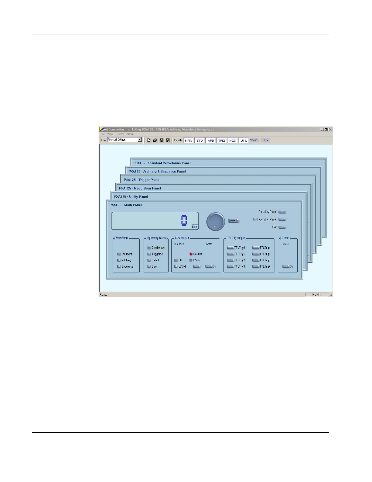
Figure 1-2, ArbConnection – Control Panels..................................................................1-4
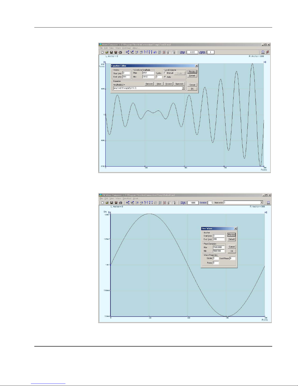
Figure 1-3, ArbConnection – Wave Composer ..............................................................1-5
Figure 1-4, ArbConnection – FM Composer ..................................................................1-5
Figure 1-5a, Segment 1 – Sin (x)/x Waveform .............................................................1-13
Figure 1-5b, Segment 2 – Sin Waveform .....................................................................1-13
Figure 1-5c, Segment 3 – Pulse Waveform .................................................................1-14
Figure 1-5d, Sequenced Waveforms............................................................................1-14
Figure 2-1, Add New Hardware Wizard..........................................................................2-6
Figure 2-2, Search for PXA125 Driver............................................................................2-7
Figure 2-3, Specify PXA125 Driver Location..................................................................2-8
Figure 2-4, Specify Subfolder for Your Instrument .........................................................2-9
Figure 2-5, Device Driver Detected ................................................................................2-9
Figure 2-6, Copying Device Driver ...............................................................................2-10
Figure 2-7, Finish Copying Device Driver.....................................................................2-10
Figure 2-8, Checking Driver Installation .......................................................................2-11
Figure 2-9, The Welcome to the Found New Hardware Wizard...................................2-12
Figure 2-10, Install Hardware Device Drivers...............................................................2-13
Figure 2-11, Locate Driver Files ...................................................................................2-13
xi
Page 12

User Manual PXA125
Figure 2-12, Copying Device Drivers ...........................................................................2-14
Figure 2-13, Driver Files Search Results .....................................................................2-15
Figure 2-14, Completing the Found New Hardware Wizard ........................................2-15
Figure 2-15, Device Manager....................................................................................... 2-16
Figure 2-16, CD’s GUI.................................................................................................. 2-18
Figure 2-17, Install preparation ....................................................................................2-19
Figure 2-18, First Installation Step ...............................................................................2-20
Figure 2-19, Customer Information Step......................................................................2-20
Figure 2-20, Selecting Setup Type...............................................................................2-21
Figure 2-21, Selecting Destination ...............................................................................2-22
Figure 2-22, Selecting Features...................................................................................2-22
Figure 2-23, Selecting ArbDetector Icon options .........................................................2-23
Figure 2-24, Setup Complete .......................................................................................2-24
Figure 2-25, The ArbDetector Icon at the Startup Tray................................................2-24
Figure 2-26, ArbDetector Icon Options ........................................................................2-25
Figure 2-27, The ArbDetector Dialog Box ....................................................................2-25
Figure 2-28, The Settings Tab .....................................................................................2-27
Figure 2-29, Editing Chassis Number and Slot Location .............................................2-27
Figure 2-30, Communicating with your Instrument ......................................................2-29
Figure 3-1, The Opening Screen....................................................................................3-3
Figure 3-2, ArbConnection’s Toolbars ...........................................................................3-5
Figure 3-3, The Main Panel............................................................................................3-8
Figure 3-4, The Standard Waveforms Panel................................................................ 3-12
Figure 3-5, The Arbitrary & Sequence Panel ...............................................................3-14
Figure 3-6, The Segment Table ...................................................................................3-16
Figure 3-7, The Sequence Table .................................................................................3-18
Figure 3-8, The Trigger Panel ......................................................................................3-20
Figure 3-9, The Modulation Panel................................................................................3-23
Figure 3-10, The Utility Panel.......................................................................................3-26
Figure 3-11, The Multi-Instrument Synchronization Panel ........................................... 3-27
Figure 3-12, Multi-Instrument Synchronization Error Message....................................3-27
Figure 3-13, System Control and the Command Editor ...............................................3-29
Figure 3-14, The Wave Composer Opening Screen....................................................3-31
xii
Page 13

User Manual PXA125
Figure 3-15, The Save Wave As… Dialog Box ............................................................3-32
Figure 3-16, Zooming In on Waveforms.......................................................................3-35
Figure 3-17, An Example of Generating Sine Waveforms From the Built-in Library ....3-36
Figure 3-18, The Toolbar Icons....................................................................................3-37
Figure 3-19, The Waveform Screen .............................................................................3-41
Figure 3-20, The FM Composer Opening Screen ........................................................3-43
Figure 3-21, The FM Composer Save As… Dialog Box...............................................3-44
Figure 3-22, An Example of Generating Modulating Sine From the Built-in Library.....3-47
Figure 3-23, The Equation Editor Dialog Box...............................................................3-48
Figure 3-24, Using the Equation Sample to Combine Two Waveforms .......................3-52
Figure 3-25, Using the Equation Editor to Modulate Sine Waveforms .........................3-53
Figure 3-26, Using the Equation Editor to Add Second Harmonic Distortion ...............3-54
Figure 3-27, Using the Equation Editor to Generate Exponentially Decaying
Sinewave ...........................................................................................................3-55
Figure 3-28, Using the Equation Editor to Build Amplitude Modulated Signal with ............
Upper and Lower Sidebands ..............................................................................3-56
Figure 3-29, Combining Waveforms Into Equations.....................................................3-57
Figure 3-30, Generating FM markers ...........................................................................3-59
Figure 4-1, SCPI Status Registers ...............................................................................4-73
List of Tables
Table 4-1, Model PXA125 SCPI Commands List Summary.........................................4-25
xiii
Page 14

User Manual PXA125
This page intentionally left blank
xiv
Page 15

Chapter 1
f
r
PORTRAYAL
What’s In This
Chapter
Introduction
Conventions
Used in this
Manual
This chapter contains general and functional description of the Model
PXA125 Arbitrary Waveform Generator. It also describes the front
panel connectors and operational modes and provides description o
all features available with the instruments.
Model PXA125 is a single-channel PXI-based Arbitrary Waveform
Generator. It is a high performance waveform generator that
combines three powerful instruments in one small package: function
generator, Waveform generator and modulation generator. Supplied
free with the instrument is ArbConnection software, which is used fo
controlling the PXA125 and for generating, editing and downloading
waveforms from a remote computer. The following highlights the
PXA125 and ArbConnection features.
The following conventions may appear in this manual:
NOTE
A Note contains information relating to the use of this product
CAUTION
A Caution contains information that should be followed to avoid personal
damage to the instrument or the equipment connected to it.
PXA125 Series
WARNING
A Warning alerts you to a potential hazard. Failure to adhere to the
statement in a WARNING message could result in personal injury.
The following symbol may appear on the product:
CAUTION:
Refer to Accompanying Documents
This refers you to additional information contained in this manual. The
corresponding information in the manual is similarly denoted.
• PXI Single Slot Module
Page 16

User Manual PXA125
Feature Highlights
• 125 MS/s sample clock frequency
• Built-in standard waveforms. Up to 50 MHz sinewave output
• 10 digits frequency setting, limited by 1 µS/s
• 14-bit vertical resolution
• 2 Meg memory depth
• Ultra fast waveform downloads
• 1 ppm clock stability
• Extremely low phase noise carrier
• Frequency agility: FSK, ramped FSK, sweep, FM
• Trigger start phase control and breakpoints
• Built-in sequence generator
• Multiple instrument synchronization with tight phase control
1-2 Portrayal
Page 17
User Manual PXA125
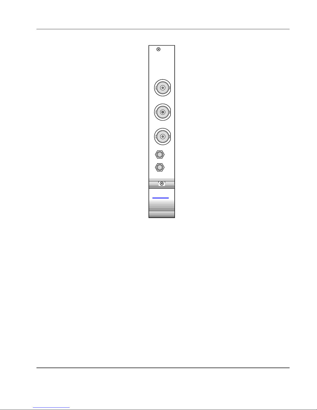
125MS/s
WAVEFORM
GENERATOR
PXA125
OUTPUT
SYNC OUT
TRIG IN
SINE OUT
1Vp-p
10M REF IN
TTL
ArbConnection
Feature
Highlights
LeCroy
Figure 1-1, PXA125
• Three powerful tools in one software package: Instrument control
panel, Waveform composer and FM signal composer
• Detailed virtual front panels control all PXA125 functions and
modes
• Wave composer generates, edits and downloads complex
waveforms
• FM wave composer generates and downloads complex
modulating signals
• Automatic detection of active instruments
• Equation editor generates waveforms from equations
• SCPI command and response editor simulates ATE operation
Portrayal 1-3
Page 18
User Manual PXA125
• Translates waveform coordinates from ASCII and other formats
• Simplifies generation of complex sequences
1-4 Portrayal
Figure 1-2, ArbConnection - Control Panels
Page 19
User Manual PXA125
Figure 1-3, ArbConnection - Wave Composer
Figure 1-4, ArbConnection - FM Wave Composer
Portrayal 1-5
Page 20

User Manual PXA125
r
r
r
f
f
Functional
Description
Output Functions
Frequency
Amplitude
Detailed functional description is given following the general
description of the features and functions available with the PXA125.
Model PXA125 is completely digital. There are no analog functions
resident in its hardware circuits. Data has to be downloaded to the
instrument for it to start generating waveforms. The instrument can
generate a few standard functions such as sine wave, triangula
wave and square wave. Each time that a standard function is
required, the instrument calculates its coordinates and places them in
the waveform memory. Therefore, every time a standard function is
selected, minimal time is required for the controller to compute the
function and load its data to the waveform memory.
Waveform frequency and sample clock are programmed with 10
digits, limited only by 1 µS/s. Frequency accuracy of the output
waveform is determined by the clock reference, CLK10, which
provides 100ppm accuracy and stability over time and temperature.
The output level may be programmed from 160 mV to 16 Vp-p into
open circuit, or 80 mV to 8 V into 50Ω. Offset may be applied to the
output to shift the signal either positive or negative. Offset and
amplitude are inter-related, so make sure you understand the offsetamplitude ranges before you apply offset to your signal.
Trigger Modes
Arbitrary Waveforms
Memory Segmentation
Besides its normal continuous mode, the PXA125 responds to a
variety of trigger sources. The output waveform may be gated,
triggered, or generate a counted burst of waveforms. A built-in trigge
generator, having a programmable period can be used as a
replacement of an external trigger source. The internal trigge
generator can be programmed with resolution of 7 digits. The
PXA125 can be programmed to output triggers on one or more of 8
trigger lines that are connected to P2, as well as, be programmed to
respond to these same trigger lines.
The Model PXA125 generates arbitrary waveforms with 14 bits o
vertical resolution. Any waveform it generates must first be loaded to
its waveform memory. The arbitrary waveform memory is a bank o
14-bit words. Each word represents a point on the horizontal
waveform scale. Each word has a horizontal address that can range
from 0 to 2,097,152 and a vertical address that can range from -8192
to +8191 (14 bits). Using a high speed clocking circuit, the digital
contents of the arbitrary waveform memory is extracted and routed to
the Digital to Analog Converter (DAC). The DAC converts the digital
data to an analog signal, and the output amplifier completes the task
by amplifying or attenuating the signal at the output connector.
There is no need to use the entire memory every time an arbitrary
waveform is generated. The waveform memory can be divided into
1-6 Portrayal
Page 21

User Manual PXA125
f
r
r
smaller segments and different waveforms can be loaded into
individual segment. The various segments may then be loaded into a
sequence table to generate long and complex waveforms. The
sequence table can link up to 4096 segments, while each segment
can loop up to 128 K times.
Remote Control
Frequency Agility
The instrument must be used in conjunction with a host computer. All
of its functions, modes and parameters are fully programmable using
SCPI commands and syntax. There are three ways to program the
Model PXA125, the first being low-level programming of each
individual parameter, using SCPI commands. The second alternative
is to use ArbConnection for high-level programming. ArbConnection
is a software package supplied with the PXA125 that simulates a
mechanical front panel. It has all the necessary push buttons,
displays and dials to operate the instrument as if you were using it on
the bench. The third alternative is using application specific drivers,
such LabVIEW.
The PXA125 must be programmed to generate waveforms.
Therefore, it is recommended that the user becomes familiar with its
basic features, functions and programming concepts as described in
this and subsequent chapters.
The instrument generates its sample clock from a DDS circuit (direct
digital synthesis). The DDS circuit enables frequency agility through
the complete frequency range of the PXA125. Having such an
enormous range opens the door for a wide range of applications such
as wide band sweep, FSK and frequency modulation. The PXA125
can generate FSK, Ramped FSK and Linear or Logarithmic sweep.
The instrument can also frequency modulate its carrier using one o
its built-in waveforms, or with can also generate any user-defined
modulating signal, which can be downloaded using the FM wave
composer.
Multi-Instrument
Synchronization
Supplied
There are applications requiring 2 or more synchronized channels.
Synchronization between completely independent, free-running
instruments is not an easy task. Besides distribution of the sample
clock to all instruments, each instrument has to be told when to start
generating waveforms so that all waveforms start from the same point
and with the same phase. Also, triggering multiple instruments to
achieve synchronization is not enough because it will generate a jitte
of ±1 count.
The PXA125 is using Backplane, daisy-chained connections to
synchronize between modules and the only limitation of the numbe
of synchronized instruments is determined by the size of the cage.
The instrument is supplied with a CD that includes an Instruction
Portrayal 1-7
Page 22

User Manual PXA125
r
r
Accessories
Specifications
Functional
Description
Front Panel
Connectors
Manual, ArbConnection for Windows 95/98/ME/2000/XP/NT and plug
& play drivers.
Instrument specifications are listed in Appendix A. These
specifications are the performance standards or limits against which
the instrument is tested. Specifications apply under the following
conditions: output terminated into 50Ω after 30 minutes of warm up
time, and within a temperature range of 20°C to 30°C. Specifications
outside this range are degraded by 0.1% per °C.
A detailed functional description is given in the following paragraphs.
The description is divided into logical groups: front panel connectors,
operating modes, output type, output state, filters and
synchronization.
The PXA125 has 3 BNC connectors on its front panel: main and
SYNC outputs and trigger input. There are also 2 SMB connectors:
sine output and 10 MHz reference input. These connectors are
described below.
Output
SYNC Output
TRIG/FSK IN
The output connector outputs fixed (pre-defined) waveforms to 50
MHz, user (arbitrary) and sequenced waveforms with sampling clock
to 125 MS/s. Output impedance is 50Ω, that is, the cable connected
to this output should be terminated with 50Ω load. Amplitude
accuracy is calibrated when connected to a 50Ω load. The amplitude
is doubled when the output impedance is above 1 MΩ.
The SYNC output generates a single TTL pulse for synchronizing
other instruments (i.e., an oscilloscope) to the output waveform. The
SYNC signal always appears at a fixed point relative to the waveform.
The location of the SYNC signal along the waveform is
programmable. The SYNC output is also used as marker output when
the sweep, or FM functions are turned on.
In general, this input accepts signals that stimulate generation of output waveforms. The trigger input is inactive when the generator operates in continuous mode. When placed in trigger, gated or burst
modes, the trigger input is made active and waits for the right condition to trigger the instrument. In trigger and burst modes, the trigge
input is edge sensitive, i.e., it senses transitions from high to low o
from low to high to trigger the PXA125. The direction of the transition
is programmable. In gated mode, the trigger input is level sensitive,
1-8 Portrayal
Page 23

User Manual PXA125
pk-p
i.e., the generator is gated when the logic level is high and idle when
the level is logic low. Trigger level for this input is TTL.
The same input is used in FSK mode, where the output hops between two frequencies – carrier and shifted frequencies. The output
generates carrier frequency when the FSK input is false and shifted
frequency when the FSK input is true.
The trigger input is also used as stop and start input when the
PXA125 is placed in Arm mode.
SINE OUT
REF IN
Operating Modes
Continuous Mode
This SMB connector outputs dc coupled, fixed level (1 V
50Ω) sine waveforms. This output is derived directly from the sample
clock generator and is active at all times, regardless of present
operating mode of the PXA125. The frequency of the sine output is
programmed using the sample clock parameter. Frequency agility
and modulation affect this output directly. The sine waveform output
is programmed to 125 MHz, so it may serve as an additional output to
those available on the front panel.
This SMB connector accepts 10 MHz, TTL level reference signal. The
external reference input is available for those applications requiring
better accuracy and stability reference than the one provided inside
the PXA125. The reference input is active only after selecting the
external reference source mode.
The PXA125 can be programmed to operate in one of four operating
modes: continuous, triggered, gated and (counted) burst. These
modes are described below.
In normal continuous mode, the selected waveform is generated
continuously at the selected frequency, amplitude and offset.
k
into
Portrayal 1-9
Page 24

User Manual PXA125
r
f
f
Triggered Mode
Gated Mode
In triggered mode, the PXA125 circuits are armed to generate one
output waveform. The trigger circuit is sensitive to transitions at the
trigger input. Select between positive or negative transitions to trigge
the instrument. When triggered, the generator outputs one waveform
cycle and remains idle at the first point of the waveform. The
instrument can be armed to receive a trigger signal from either the
front panel connector, soft command, an internal trigger generator,
from one of 8 backplane trigger lines or from a backplane STAR line.
As an alternative to an external source, the PXA125 has a built-in
trigger generator that can be programmed through a wide range o
frequencies and with 7 digits of resolution.
The trigger signal, whether it comes from the front panel, backplane
or from a soft command, has to pass through some electrical circuits.
These circuits cause small delay known as system delay. System
delay cannot be eliminated completely and must be considered when
applying a trigger signal. It defines how long it will take from a valid
trigger edge to the moment that the output reacts.
In gated mode, the PXA125 circuits are armed to generate output
waveforms as long as a gating signal is present. Unlike the triggered
mode, the gated mode is level sensitive. When the gating signal goes
low, the waveform at the output connector is first completed and the
output reverts to an idle state. The idle amplitude level, after the
gating signal goes low, is the last point on the waveform.
Burst Mode
Frequency Agility
1-10 Portrayal
The burst mode is an extension of the triggered mode where the
generator can be programmed to output a pre-determined number o
waveforms. The sources to trigger a burst are the same as for the
trigger mode.
Using the latest DDS (direct digital synthesis) technology, the
PXA125 is extremely agile. Operations like sweep, FSK and FM are
directly derived from the DDS circuit by controlling its input bits.
Frequency agility is described below.
Page 25

User Manual PXA125
r
r
r
Sweep
FSK
Ramped FSK
The PXA125 can sweep from minimum to maximum sample clock
frequency settings. You may select to sweep up or down using linea
or logarithmic increments. Sweep time is programmable from 1 ms to
1000 seconds with 7 digits. The sweep start and stop frequencies
program the front-panel sine output connector. You may also use the
sweep from the main output but must first calculate start stop
frequencies, depending on the present sample clock frequency and
waveform length. You may use the sweep in continuous, triggered, o
gated modes.
FSK (frequency shift keying) function controls the sine output
connector. The trigger input is used to flag the PXA125 when to
output carrier frequency (trigger false) or when it should switch to the
shift frequency (trigger true). You may also use the FSK function from
the front panel as long as you do your own calculation of carrier and
shifted frequencies, depending on the present sample clock
frequency and waveform length.
Ramped FSK is the same as the FSK function except the output
frequency is ramped instead of switched to the shift frequency. Ramp
time is programmable with 3 digits from 100 µs to 1 second.
FM
Output Type
The FM function modulates the PXA125 sample clock frequency. You
can frequency modulate the output either with built-in waveforms, o
download complex waveforms to the modulation memory. Using the
latest DDS technology, the modulation is wide band and extremely
linear. FM can be used in continuous, triggered and gated modes.
The PXA125 can generate two types of frequency modulation: 1)
Standard and 2) Arbitrary. In standard mode, the modulating
waveform is selected from a built-in library of 4 standard waveforms:
sine, triangle, square and ramped. In arbitrary mode, the modulating
signal is downloaded to the modulation waveform memory. There are
20,000 points allocated specifically for the arbitrary memory that is
used for arbitrary frequency modulation.
The PXA125 can output three types of waveforms: standard (Fixed),
arbitrary (User) and sequenced waveforms. Description of the various
waveform types that the instrument can generate is given below.
Portrayal 1-11
Page 26

User Manual PXA125
r
r
Standard (FIXED)
Waveforms
Arbitrary (User)
Waveforms
The PXA125 must pre-load its memory before it can generate
waveforms. On power up, the waveform memory has no specific
data. The sine waveform, being the default waveform on power on, is
computed and loaded to the waveform memory as part of the reset
procedure. From this moment on, every time that another standard
waveform is selected, it is being computed and loaded to the
waveform memory.
Waveforms are written from the same start address. Therefore, every
time that a new waveform is selected, there is some minimal time fo
the processor to compute and download the data to the memory.
The PXA125 can be programmed to output one of nine standard
waveform shapes: sine, triangle, square, pulse/ramp, sine(x)/x pulse,
gaussian pulse, rising/decaying exponential pulse, noise and dc.
There are some parameters associated with each waveform, which
modify the shape of the waveform to better suit your needs. Fo
example, different start phase for the sine waveform can be
programmed for each channel to create phase offsets between the
two instruments.
The arbitrary waveform memory is capable of storing one or more
user-defined waveforms. As was discussed before, the PXA125 is
supplied with 2 Meg memory bank. There are up to 2 Meg points that
can be allocated to one single waveform. On the other hand, there is
no need to use the entire memory for only one waveform; The
memory can be divided into smaller segments and loaded with
different waveforms and the instrument can be programmed to output
one segment at a time.
1-12 Portrayal
Loading data to arbitrary waveform memory can be a time-consuming
task, especially if all 2 Meg points are loaded in one shot. The
PXA125 utilizes a DMA (direct memory access) concept that speeds
data transfer from host computer to the instrument.
Page 27
User Manual PXA125
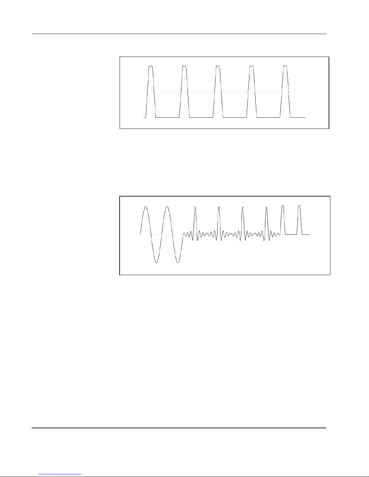
Sequenced
Waveforms
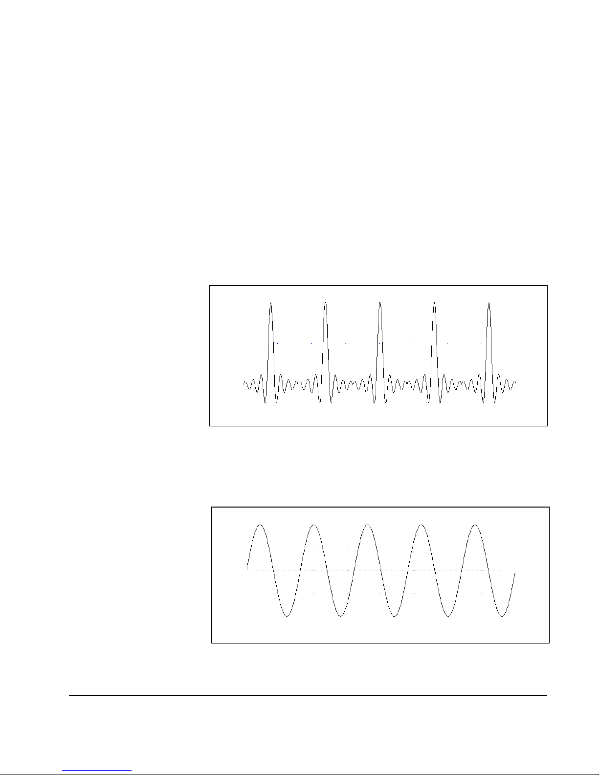
The sequence generator is a powerful tool that lets you link and loop
segments in any way you desire. As a simple example of a
sequenced waveform, look at Figures 1-5a through 1-5c. The
waveforms shown in these figures were placed in memory segments
1, 2 and 3, respectively. The sequence generator takes these three
waveforms links and loops them in a predefined order to generate the
waveform shown in Figure 1-5d.
The sequence circuit is useful for generating long waveforms with
repeated sections. The repeated waveform has to be programmed
once and the repeater loops on this segment as many times as
selected. When in sequenced mode, there is no loss of time between
linked or looped segments.
Figure 1-5a, Segment 1 – Sin (x)/x Waveform
Figure 1-5b. Segment 2 – Sine Waveform
Portrayal 1-13
Page 28
User Manual PXA125
r
Figure 1-5c Segment 3 – Pulse Waveform
The following sequence was made of segment 2 repeated twice,
segment 1 repeated four times, and segment 3 repeated two times.
Output State
Filters
1-14 Portrayal
Figure 1- 5d. Sequenced Waveforms
The main outputs can be turned on or off. The internal circuit is
disconnected from the output connector by a mechanical switch
(relay). This feature is useful for connecting the main outputs to an
analog bus. For safety reasons, when power is first applied to the
chassis, the main output is always off.
Two filters are built into the PXA125. These filters are available fo
use in various applications such as the creation of high frequency
sine waves and removing the staircase effect from waveforms that
are generated with high frequency clock rates. The filters are also
used for reconstructing the standard sine waveform.
Page 29

User Manual PXA125
Programming
The PXA125
The PXA125 does not have front panel control capability. Also,
waveform data and sequence tables must be loaded to the PXA125
from a host computer before it can be output arbitrary or sequenced
waveforms. There are a number of ways to “talk” to the instrument.
They all require that an appropriate software driver be installed in the
host computer. The rest is a matter of practice and knowledge of the
language in use. These topics are discussed in later chapters.
Low level programming of the PXA125 is accomplished using SCPI
(Standard Commands for Programmable Instruments) language.
Programming aspects are covered in Chapter 4.
Supplied with the PXA125 is a PC software package called
ArbConnection. This software provides a user interface that allows
interacting with and controlling the PXA125 directly. Details on how to
use ArbConnection are given in Chapter 3.
Portrayal 1-15
Page 30

Chapter 2
r
r
INSTALLATION
Installation
Overview
Unpacking and
Initial Inspection
Safety
Precautions
This chapter contains information and instructions necessary to
prepare the Model PXA125 for operation. Details are provided fo
initial inspection, grounding requirements, repackaging instructions fo
storage or shipment and installation information.
Unpacking and handling of the generator requires normal precautions
and procedures applicable to handling of sensitive electronic
equipment. The contents of all shipping containers should be checked
for included accessories and certified against the packing slip to
determine that the shipment is complete.
The following safety precautions should be observed before using this
product and associated computer. Although some instruments and
accessories would normally be used with non-hazardous voltages,
there are situations where hazardous conditions may be present.
This product is intended for use by qualified persons who recognize
shock hazards and are familiar with the safety precautions required to
avoid possible injury. The following sections contain information and
cautions that must be observed to keep the PXA125 operating in a
correct and safe condition.
CAUTION
For maximum safety, do not touch the product, test
cables, or any other instrument parts while power
is applied to the circuit under test. ALWAYS
remove power from the entire test system before
connecting cables or jumpers, installing or
removing cards from the chassis. Do not touch any
object that could provide a current path to the
common side of the circuit under test or power line
(earth) ground. Always keep your hands dry while
handling the instrument.
Page 31

User Manual PXA125
Operating
Environment
The PXA125 is intended for operation within a PXI chassis as a
plug-in module. Ensure the PXI chassis being used to host the PXA
125 fully conforms to the latest PXI specifications.
The PXA125 is intended for indoor use and should be operated in a
clean, dry environment with an ambient temperature within the range
of 0 °C to 40 °C.
WARNING
The PXA125 must not be operated in explosive, dusty, or wet
atmospheres. Avoid installation of the module close to strong
magnetic fields.
The design of the PXA125 has been verified to conform to EN
61010-1 safety standard per the following limits:
Installation (Overvoltage) Category I (Measuring terminals)
Pollution Degree 2
Installation (Overvoltage) Category I refers to signal level, which is
applicable for equipment measuring terminals that are connected to
source circuits in which measures are taken to limit transient
voltages to an appropriately low level.
Pollution Degree 2 refers to an operating environment where
normally only dry non-conductive pollution occurs. Occasionally a
temporary conductivity caused by condensation must be expected
Power
Requirements
Grounding
Requirements
The PXA125 operates from within a PXI chassis. DC Voltages are
supplied to the instrument from the PXI backplane. The instrument
requires a variety of DC voltages as outlined in the Specifications
section (Appendix A). Ensure the PXI chassis is capable of
delivering required voltages and has sufficient current to drive the
generator.
CAUTION
Disconnect power to the PXI Chassis before installing or removing
the PXA125.
To conform to the applicable safety and EMC requirements, ensure
that the PXA125 instrument panel and the PXI chassis are “earth”
grounded.
Installation 2-17
Page 32

User Manual PXA125
r
CAUTION
The outer shells of the front panel terminals (OUTPUT, SYNC OUT,
TRIG IN, SINEOUT, 10M REF IN) are connected to the instrument’s
chassis and therefore to the safety ground.
CAUTION
Do not attempt to float the OUTPUT from ground as it may damage
the PXA125 and other equipment connected to the PXA125 I/O
connectors.
Calibration
Abnormal
Conditions
Long Term
Storage or
Repackaging For
Shipment
The recommended calibration interval is one year. Calibration
should be performed by qualified personnel only.
Operate the PXA125 only as intended by the manufacturer. If you
suspect the PXA125 has been impaired, remove it from the PXI
Chassis and secure against any unintended operation. The
PXA125 protection is likely to be impaired if, for example, the
instrument fails to perform the intended measurements or shows
visible damage.
WARNING
Any use of the PXA125 in a manner not specified by the
manufacturer may impair the protection provided by the instrument
If the instrument is to be stored for a long period of time or shipped
immediately, proceed as directed below. If you have any questions,
contact your local LeCroy representative or the LeCroy Custome
Service Department.
1. Repack the instrument using the wrappings, packing material
and accessories originally shipped with the unit. If the original
container is not available, purchase replacement materials.
2. Be sure the carton is well sealed with strong tape or metal
3. Mark the carton with the model and serial number. If it is to be
2-18 Installation
straps.
shipped, show sending and return address on two sides of the
box.
NOTE
If the instrument is to be shipped to LeCroy for
calibration or repair, attach a tag to the instrument
identifying the owner. Note the problem,
symptoms, and service or repair desired. Record
Page 33

User Manual PXA125
Preparation For
Use
the model and serial number of the instrument.
Show the returned authorization order number
(RMA) as well as the date and method of shipment.
ALWAYS OBTAIN A RETURN AUTHORIZATION
NUMBER FROM THE FACTORY BEFORE SHIPPING
THE INSTRUMENT TO LeCroy.
Preparation for use include removing the instrument from the bag,
installing the PXA125 inside the PXI chassis, copying instrument
drivers to the computer and installing the graphical interface
(ArbConnection).
Removing the
Instrument from
the Bag
Installation
The PXA125 is supplied in an antistatic bag. Check the seal on the
bag to make sure the bag was not opened in a static-unsafe
environment. Place the enveloped card on static free surface and
hook yourself up with a grounding strap. Only then break the seal and
remove the card from the envelope. Hold the card at the metal panel
end. Refrain from touching the instrument with your finger at all times.
Plug the PXA125 into your PXI chassis and lift the extractor to the
upright position. Push the card firmly until the metal panel makes
contact with the metal edge of the PXI chassis. Using a suitable
screwdriver, tighten the two retaining screws, top and bottom.
CAUTION
Disconnect power to the PXI Chassis before
installing or removing the PXA125. An attempt to
insert or remove the instrument while the power is
connected to the chassis will result in severe
damage to the instrument and will automatically
revoke your warranty.
Installing
Instrument Drivers
CAUTION
Once the PXA125 is installed in the chassis cover
all remaining open slots to ensure proper airflow.
Using the PXA125 without proper airflow will result
in damage to the instrument.
The PXA125 is a Plug & Play instrument, meaning that after you
install it in your PXI chassis, Windows will automatically detect its
presence and will ask you to supply the appropriate drivers to operate
Installation 2-19
Page 34

User Manual PXA125
r
r
r
r
r
r
this instrument. After you copy the drivers, Windows will add the
drivers to the device manager and will assigns resources for the
instrument.
The PXA125 is supplied with a CD that contains the *inf file fo
installing the necessary drivers for operating the instrument on you
computer. Follow the instructions below to install the driver to you
computer.
Minimum System
Requirements
Windows Software
Installation
Minimum host system requirements for the instrument are as follows:
1. Windows 95/98/ME/NT/2000/XP
2. 32MB of RAM, 128MB or more recommended
3. 20MB hard drive space
Note
The install program will automatically detect older
software version and you will be provided with a
choice of either removing it and installing newer
versions, or keeping your old installation intact.
The install program will not remove instrument
drivers. In case you want to remove the instrument
driver from your computer, go to the Windows
Device Manager (as shown in Figure 2-8) and
remove the Arbitrary Waveform Generator Model
PXA125 under the LeCroy heading.
In general, installation is very similar for different Windows variants
however, you should follow the exact procedure as applicable fo
you’re your computer. The following paragraphs will guide you
through device driver installation for Windows 95/98, ME, Windows
2000/XP and Windows NT.
Windows 95/98/ME
Device Driver Installation
A device driver is necessary for the PXA125 software to communicate
with the PXI boards. Windows applications cannot communicate with
PXI devices without a device driver installed. The PXA125’s
installation CD includes instrument drivers for supporting the required
Windows platform. In Windows 95/98/ME, the installation package
cannot automatically assign device drivers for PXI devices and
therefore leaving for the Plug & Play Manager the responsibility fo
detecting devices and prompting the user for the correct driver. To
assign a driver to a device, Windows refers to an *.INF file. The *.INF
file provides instructions for Windows as to which driver files to install
and which registry entries to insert. To install a driver for you
PXA125, complete the following steps:
2-20 Installation
Page 35

User Manual PXA125
r
1. Power down your computer and PXI chassis.
2. Insert the PXI PXA125 board into a free PXI slot.
3. Power on your PXI chassis
4. Power on the computer. Windows should first detect the new
hardware device with a “New Hardware Found” message box.
5. Windows displays the “Add New Hardware Wizard” as shown in
Figure 2-1, which will search for new drivers
6. Follow the procedure as shown below.
7. After installing the PXI PXA125 successfully (see the previous
section
), you’ll be prompted to reboot your computer.
Figure 2-1 – Add New Hardware Wizard
Press Next and select one of the options in the dialog box below. We
recommend that you check the “Search for the best driver for you
device” option as shown in Figure 2-2.
Installation 2-21
Page 36

User Manual PXA125
r
r
r
Figure 2-2 – Search for PXA125 Driver
Press Next and you’ll now be prompted to select the location of the
required *.INF file on your computer as shown in Figure 2-3.
The PXA125 is supplied with installation CD. Insert this CD into you
CD-ROM drive and check the “Specify a location” option as shown
below. If you already have the *.INF installed somewhere on you
computer, you can specify your custom location. Either type in the
complete path or click on the Browse button to find the path to you
previous driver location.
2-22 Installation
Page 37

User Manual PXA125
Figure 2-3– Specify PXA125 Driver Location
Assuming that this is your first-time installation, press Browse find the
Win9xdrv subfolder that is located in the Drivers folder on the
supplied CD, as shown in Figure 2-4.
Installation 2-23
Page 38

User Manual PXA125
r
Figure 2-4 – Specify Subfolder for Your instrument
Press OK, then next; Windows will automatically detect the device
driver and will show the next dialog box, as shown in Figure 2-5.
Check the device description to make sure it agrees with you
instrument description.
2-24 Installation
Figure 2-5 – Device Driver Detected
Page 39

User Manual PXA125
Press Next and observe that Window copies the files from the CDROM drive to your hard drive, as shown in Figure 2-6.
Figure 2-6. Copying Device Driver
After Windows has completed copying the device drivers, you can
click on the Finish button to complete the installation process.
Figure 2-7 – Finish Copying Device Driver
Installation 2-25
Page 40

User Manual PXA125
The next step is necessary to verify that the device driver was
installed properly and is displayed correctly in the System Device
Manger. Do the following:
1. Click on the Start button, then Settings and then Control Panel.
2. In the Control Panel dialog box, find the icon labeled System.
3. Double-click on the System icon and then on the Device
Manager tab.
4. Click on LeCroy. If you installed the driver properly, your device
manager should show the Arbitrary Waveform Generator Model
PXA125 as shown in the figure 2-8 below.
2-26 Installation
Figure 2-8. Checking Driver Installation
Click on “Cancel” to remove the System Properties dialog box from
the screen.
Page 41

User Manual PXA125
r
r
Windows 2000/XP Device
Driver Installation
A device driver is necessary for the PXA125 software to communicate
to the PXI boards. Windows applications cannot communicate to PXI
devices without a device driver installed. The PXI PXA125’s
installation CD includes instrument drivers for supporting the required
Windows platform. In Windows 2000/XP, the installation package
cannot automatically assign device drivers for PXI devices and
therefore leaving for the Plug & Play Manager the responsibility fo
detecting devices and prompting the user for the correct driver. To
assign a driver to a device, Windows refers to an *.INF file. The *.INF
file provides instructions for Windows as to which driver files to install
and which registry entries to insert. To install a driver for you
PXA125, complete the following steps:
1. Power down your computer and PXI chassis.
2. Insert the PXI PXA125 board into a free PXI slot.
3. Power on your PXI chassis
4. Power on the computer. Windows should first detect the new
hardware device with a “Found New Hardware Wizard”
message box.
5. Windows then displays the “Found New Hardware Wizard” as
shown in Figure 2-9, which will search for new drivers
6. Follow the procedure as shown below.
Figure 2-9 – The Welcome to the Found New Hardware
Wizard
Press Next and select one of the options in the dialog box below. We
recommend that you check the “Search for a suitable driver for my
device” option as shown in Figure 2-10.
Installation 2-27
Page 42

User Manual PXA125
r
Figure 2-10 – Install Hardware Device Drivers
Press Next and you’ll now be prompted to select the location of you
driver files on your computer as shown in Figure 2-11. Check the
“Specify a Location” option only.
Figure 2-11 – Locate Driver Files
2-28 Installation
Page 43

User Manual PXA125
r
The PXA125 is supplied with an installation At this time, CD. Insert
this CD into your CD-ROM drive. If you already have the instrument
drivers installed somewhere on your computer, you can specify you
custom location. Either type in the complete path or click on the
Browse button to identify your driver location.
NOTE
After you insert the installation CD Windows
2000/XP will automatically load the autorun
program and the CD interface will show on your
monitor, similar to what you see in Figure 2-16. The
CD menu is not required for the driver installation
so you can either leave the menu on screen and
ignore it for now or click on Exit to remove the
application from your desktop. The installation CD
must be left in the CD-Rom drive for the
continuation of the installation process.
Press Browse… and specify the subfolder W2kdrv located in the
Drivers folder on your installation CD, as shown in Figure 2-12. Press
OK to acknowledge the selected path.
Figure 2-12 – Copying Device Drivers
Installation 2-29
Page 44

User Manual PXA125
Windows displays the Driver Files Search Results as shown in Figure
2-13. Click Next and then Finish to complete the installation process.
Figure 2-13 – Driver Files Search Results
Figure 2-14 – Completing the Found New Hardware Wizard
2-30 Installation
Page 45

User Manual PXA125
The next step is necessary to verify that the device driver was
installed properly and is displayed correctly in the System Device
Manger. Do the following:
1. Click on the Start button, then Settings and then Control Panel.
2. In the Control Panel dialog box, find the icon labeled System.
3. Double click on the System icon and then on the Hardware
4. On the Hardware tab click on the Device Manager button.
5. Click on LeCroy. If you installed the driver properly, your device
manager should show the Arbitrary Waveform Generator Model
PXA125 as shown in figure 2-15.
Figure 2-15 – Device Manager
Click on “X” to remove the System Properties dialog box from the
screen.
Installation 2-31
Page 46

User Manual PXA125
r
r
r
Windows NT Device
Driver Installation
A device driver is necessary for the PXA125 software to communicate
with the PXI boards. Windows applications cannot communicate with
PXI devices without a device driver installed. The PXA125’s
installation CD includes instrument drivers for supporting various
Windows platforms.
Since Windows NT does not have Plug & Play capability, the
installation process is completely different than how it’s done on othe
Windows platforms. Actually, the Windows NT installation is
transparent and automatic while you install some software utilities that
are necessary to operate and detect the instrument on your PC.
These utilities are called ArbConnection and ArbDetector. Detailed
description of these utilities is given in other sections of the manual
however, if you are an NT user, you must install these utilities before
your NT system will be able to detect and control the PXA125.
To install your Windows NT driver and other software utilities,
complete the following steps:
1. Power down your computer and PXI chassis.
2. Insert the PXA125 board into a free PXI slot.
3. Power on your PXI chassis
4. Power on your computer
5. Insert the CD into your CD-ROM drive.
6. Start installing the software using the procedure for “Installing
ArbConnection and ArbDetector” utilities as described below.
Installing
ArbConnection
and ArbDetector
2-32 Installation
ArbConnection and ArbDetector are two software utilities that must be
installed on your computer for you to be able to operate and control
the PXA125. ArbConnection has three basic function: 1) Control
instrument setups, 2) Create, edit and download complex arbitrary
waveforms to your instrument and 3) Create, edit and download
complex (frequency) modulating waveforms.
Advanced users may want to write their own applications to control
the PXA125 functions and features. For this purpose, C++ libraries
and DLL’s are available on the CD and can be copied to you
application folder. However, if you are first time user and can’t wait to
get your hands on some controls and waveforms, it is recommended
that you install ArbConnection now. ArbConnection and waveform
generation aspects are covered in other sections of this manual.
The ArbDetector program contains device initialization and interfacing
links between your computer’s board and the PXA125’s PXI interface
chip and therefore, ArbDetector must be installed and invoked
whenever you want to use the PXA125, even if you are running you
own application and regardless of which Windows platform is installed
on your computer.
Page 47

User Manual PXA125
r
Windows NT users must install the ArbConnection and ArbDetecto
utilities as part of the basic installation process as described in the
Windows NT Device Driver Installation section of this manual. The
installation process of these two programs will automatically install
device drivers on Windows NT systems.
To proceed with the installation process, insert the supplied CD into
your CD-ROM drive and wait for a GUI (Graphical User Interface, as
shown in Figure 2-16) to pop up on your screen. If you wait for a long
time and the GUI fails to load it is possible that your computer is not
set up to load CD programs automatically. In this case, Invoke Run
and type:
N:\Autorun.exe (where N is your CD drive letter)
Figure 2-16 – CD’s GUI
To install the software click on “Install Software Utilities” and follow
the install program as shown in Figure 2-17. The preparing phase will
check few things such as if your computer has any previous
installations installed on.
Installation 2-33
Page 48

User Manual PXA125
r
r
If you are an advanced user and in preparation to write your own code
and application, you’ll have to copy support libraries and some DLL’s
from the installation CD. In this case, select the “Copy Develope
Libraries” option and specify the folder location for your application.
The function of the libraries and other programming aspects are cove
in the programming section of this manual.
2-34 Installation
Figure 2-17 – Install preparation
After finishing the “Preparing to Install” phase, the install wizard
shown in Figure 2-18 will take you to the first installation step
assuming that no problems were detected.
Page 49

User Manual PXA125
r
Figure 2-18 – First Installation Step
Press Next and type the customer details at the “Custome
Information” Window, as shown in Figure 2-19.
Figure 2-19 – Customer Information Step
Installation 2-35
Page 50

User Manual PXA125
After typing the customer details press Next and select the Setup
Type. You can select from three options: 1) Select PXA125 if you
purchased and are installing the PXA125, or 2) Select Custom if you
are an advanced user and want to refine your installation process.
We recommend that you install using options 1 or 2 above and
complete the installation process by clicking on the Next button and
then Finish. If you select the Custom option, then you’ll have to type
in some other parameters such as new path for your destination
folder and choosing which feature to install, as shown in Figures 2-21
and 2-22.
If you select the Custom option, proceed to change your Destination
Folder, as shown in Figure 2-21, by pressing the Browse button,
select the appropriate path, press OK and then press Next.
2-36 Installation
Figure 2-20 – Selecting Setup Type
Page 51

User Manual PXA125
Figure 2-21 – Selecting Destination
To select the Installed Features, as shown in Figure 2-22, select the
appropriate feature by clicking on.
Figure 2-22 – Selecting Features
Installation 2-37
Page 52

User Manual PXA125
r
Just before you finish with the installation, you’ll have to decide if you
want an icon added to the system tray. The system tray is located on
the right lower side of the screen that has icons that are loaded there
automatically every time your computer is powered up. If you select
the “No” option, ArbConnection will still launch at startup but the icon
will not show and then, to access ArbDetector you’ll have to invoke it
from the Start → Programs → StartUp Menu. The ArbDetector icon
selection dialog box is shown in Figure 2-23.
2-38 Installation
Figure 2-23 – Selecting ArbDetector Icon options
The final step to complete the installation process, you’ll be prompted
to restart your computer. You can select to either restart you
computer immediately or do it later, but remember that the software
will not function properly if you do not restart your computer.
Page 53

User Manual PXA125
A
r
r
r
The
ArbDetector
Figure 2-24 – Setup Complete
The ArbDetector detects all arbitrary waveform generators that are
plugged into the PXI chassis and lets you review instrument identity,
serial number, installed options etc. You may also use the device
detector to fine-tune your controller type, chassis size and slot
location.
Before you can start using the PXA125, you must make sure that the
rbDetector has been invoked. Look at your right lower end of you
screen and identify the Startup bar. The ArbDetector icon looks as
shown in Figure 2-25.
The ArbDetector is automatically invoked from the startup menu afte
you power on your computer. If, for any reason you cannot find the
ArbDetector icon, you’ll have to invoke it manually. From the Start
button select Programs, then Startup and finally the ArbDetecto
command. The detector will be invoked and the icon placed at the
startup tray.
Figure 2-25. The ArbDetector Icon at the Startup Tray
Installation 2-39
Page 54

User Manual PXA125
r
r
When you click on the ArbDetector icon with your right mouse button,
some options will show that will allow you to open the ArbDetecto
program, Reset all instruments to factory defaults, Delete al assigned
slot locations and Verify users in case you want to Exit the program.
The ArbDetector icon options is shown in Figure 2-26.
Figure 2-26. ArbDetector Icon Options
Using the
ArbDetector
To invoke the ArbDetector program, either double-click on the icon o
open the options window as shown in Figure 2-26 and click on the
Open ArbDetector command. Doing so, the dialog box as shown in
Figure 2-27 will open. If you cannot see the icon in your system tray,
invoke the program from the StartUp menu.
2-40 Installation
Figure 2-27. The ArbDetector Dialog Box
Page 55

User Manual PXA125
The ArbDetector dialog box is divided into two sections. The left side
looks just like the familiar explorer program. The purpose of this
explorer is to show how many devices are currently located inside
your PXI system. This program will detect waveform generators only
so please do not try using this program to detect other instruments.
There are three tabs on the right side of the dialog box. Information,
Communication… and Settings… These tabs can only be used if at
least one instrument has been found in the system. To be able to
access these tabs, click on one of the instruments on the left side to
highlight it, as shown in Figure 2-27. The information tab is
automatically updated from the instrument flash memory with the
following information: model number, maximum sample clock rate,
installed memory option, installed clock option, hardware revision,
production date and serial number. It also will show the firmware
version and its release date.
Notice the Actual Location fields. There are two parameters there that
are user controllable. These are the chassis number and actual slot
location. These parameters can be programmed in the Setting… tab.
If you have only one instrument in your system and do not care about
its actual and physical location in the system, then you do not have to
touch these fields and the instrument will perform flawlessly, even
with these fields empty. In Figure 2-27, the instrument is located in
chassis number 1 and slot number 2.
Configuring
Actual Slot
Location
The ArbDetector is flexible enough to allow you to specify the actual
slot where your instrument resides. This is important in systems that
have multiple chassis and multiple arbs, regardless if you are using
chassis connected in “star” or serial format. After you specify the
location of the instrument, external applications like ArbConnection
can access these parameters and program just the instrument you
want to access. To program slot location, click on the Settings… tab.
The Settings tab is shown in Figure 2-28.
Installation 2-41
Page 56

User Manual PXA125
r
r
Figure 2-28. The Settings Tab
The Slot Configuration as shown in Figure 2-28 is the end result afte
you assign the Chassis number and Slot parameters. To add or edit
these parameters, click on the Edit button. The Edit dialog box will
display as shown in Figure 2-29.
In the Slot Number field select your actual location of your instrument
and in the Chassis Number select the actual chassis where you
2-42 Installation
Figure 2-29. Editing Chassis Number and Slot location
Page 57

User Manual PXA125
r
f
instrument resides. To complete the chassis and slot assignment,
click on OK. The dialog box will be removed from the screen the and
Slot configuration parameters will be updated with the information you
programmed just now. Notice the 10-digit number above the slot
number. This is the serial number of your instruments as was
detected by the ArbDetector. To make sure this is the right instrument
you want to allocate, remove the instrument from your chassis and
compare to the serial number as printed on the card.
Testing
Communications
With your
Instrument
Final operation with your ArbDetector allows you to test
communication with your instrument. If you click on the
Communication… tab, the tab, as shown in Figure 2-30 will show. The
Command Editor field lets you write SCPI commands that control
instrument functions and parameters. SCPI programming is covered
in Chapter 4 of this manual. Connect your instrument to an
oscilloscope and try these simple commands just to see you’re you
instrument responds correctly:
output on will turn on your output and sinewave will be
frequency 2e6 will change output frequency to 2 MHz
volt 5 will change output amplitude to 5 Vp-p
If you are not sure about the commands and want the Command
Editor to alert on errors, check the Add “Syst:Err?” Query option. I
you make syntax errors, the errors will display in the Response field.
The example in Figure 2-30 shows 0, “No error”. Different digits and
error description will be the response if you make errors.
The Response field can also be used to query instrument settings.
Try the following queries and check the response:
output? will query output state
frequency? will query frequency setting
volt? will query amplitude setting
The commands as you type them will be saved as an history list. You
can use any command from this list by unfolding the list and selecting
a command, then clicking on Send to program this command.
Installation 2-43
Page 58

User Manual PXA125
Figure 2-30. Communicating with your Instrument
2-44 Installation
Page 59

Chapter 3
r
A
f
ArbConnection
What’s In This
Chapter
Introduction To
ArbConnection
This Chapter contains information how to install, invoke and use
ArbConnection. Introduction to ArbConnection and examples how to
program instrument controls and parameters and how to generate
waveforms and download them to the PXA125 are also given in the
following sections.
In general, ArbConnection is a utility program that serves as an aid fo
programming the Model PXA125. ArbConnection has many functions
and features of which all of them share a common purpose –
controlling PXA125 functions from remote. As minimum, to use
ArbConnection, you’ll need the following tools:
1. Computer, Pentium II or better
2. Windows 95, or higher
3. High resolution screen, at least, 1024 x 768 pixels
4. Pointing device, mouse or ball
5. PXI chassis and installed PXA125
6. Last, but not least, some basic knowledge on how to operate
computers and Windows-based programs.
ArbConnection operation is divided into three main functions: 1) Front
panel control, 2) Waveform generation and editing and 3) FM
waveform generation and editing. These operating options are
described in this chapter. But, you must install ArbConnection before
you can use it, so the next paragraphs describe installation and first
steps before going into in-depth operation.
Installing
ArbConnection
rbConnection installs as part of the general installation process o
the instrument drivers and programs. You can also install
ArbConnection alone, in case you are not interested in installing PXI
drivers but only want to test or explore its operation. The complete
installation process is outlined in Chapter 2. To install ArbConnection
without other parts of the installation package, proceed with Custom
installation and check the ArbConnection option only, as shown in
Figures 2-20 and 2-22
Page 60

User Manual PXA125
f
f
r
Quitting
ArbConnection
For the New and
Advanced Users
Before you start roaming through menus and editing commands, we
strongly recommend that you make yourself familiar with
ArbConnection basics and concept. For now quit the program and
spend some more time with this section of the manual. Point the
mouse cursor to the File menu and press the left mouse button. Move
the mouse cursor to the Exit command and press the left mouse
button.
For the New User
Learning to use ArbConnection is easy, intuitive and quick, even i
you have never used such programs before. After you have installed
ArbConnection on your computer read the following paragraphs to
learn how to find your way around ArbConnection’s menus.
Once you are familiar with the basics, you’ll continue to learn about
features, programming, and editing commands. If you can’t find the
answer to a question in this guide, call your distributor or the LeCroy
customer support service near you and we’ll gladly assist you with
your problems.
For the Advanced User
If you are already familiar with computer conventions and have basic
knowledge of Windows programming, you may want to skip some o
the following paragraphs.
Conventions Used
in This Manual
3-46 ArbConnection
This manual uses certain typographical conventions to make it easie
for you to follow instructions. These conventions are described in the
following:
[Enter, or ↵] Press the Enter or Return key.
[Esc] Press the Escape key.
[Alt-F] Press the Alt key and the key that follows, simultaneously. In
this example the key that follows is F.
[Ctrl-S] Press the Control key and the letter that follows, simultaneously. In this example, the letter is S. The control key also appears
in the menus as a target sign.
[↑] [↓] [→] [←] Press the Arrow key with the symbol pointing in the
direction specified (i.e., up, down, left, or right).
<+> Press the key for the character or word enclosed in angle
brackets. In this case, the Plus sign key.
Page 61

User Manual PXA125
The Opening
Screen
Invoke ArbConnection by double clicking on the icon. If you cannot
find the icon on your desktop, click on Start, Programs and
ArbConnection. The opening screen will show. If you installed the
program correctly, your screen should look as shown in Figure 3-1.
Figure 3-31. The opening Screen
The Startup & Communication Options dialog box is displayed at the
top. You can check the “Store and don’t show…” so next time you
invoke ArbConnection, this dialog box will not be displayed. The
purpose of this dialog box is to update the program in the way you
intend to use it. Since ArbConnection is used for other platforms, it is
extremely important to make sure that the selected communication
link for the PXA125 is PXI so the first thing to do is click on the PXI
ArbConnection 3-47
Page 62

User Manual PXA125
button to activate this link. Other options are GPIB, RS232 and VXI
but they should be disabled for now. If you press the All Platforms
button, then the program will attempt to connect every possible link,
which usually takes much longer.
The On Instrument Activation group lets you select the opening
scenario for the instrument. The various options are described below:
Reset Instrument and Panels – will reset the generator and the
control panels to factory default values. Parameter defaults are listed
in Chapter 4 of this manual.
Update Panels – can be used in case you had to leave the program
but left the generator still operating. The update Panels option will
query instrument setting and will update the control panels
accordingly. Note that waveforms cannot be read from the instrument
so only control panels will be affected from this operation. The Update
Panels option is useless if you powered down the host computer.
Update Instrument – can be used every time you invoke
ArbConnection. Every time you exit ArbConnection, an image of the
last control panel setting is automatically stored on your hard drive so
the next time you invoke the program the control panels are updated
from this image. When you use the Update Instrument option, the
instrument will update its operational settings and parameter values
only but will not download waveforms.
3-48 ArbConnection
Refresh Communications – will activate the Autodetect engine and
will attempt to reconnect all devices that respond to ArbConnection
calls. The use of this option is normally not required except in isolated
incidents that you suspect that ArbConnection has not detected all
instruments that are present in the chassis.
Work Offline – will let you use ArbConnection without actually
controlling or having an active instrument plugged in. This option also
lets you prepare and save control panel settings for later use.
Communicate Only – will make the connection between
ArbConnection and the instrument but will not synchronize between
the two. You can use this option if you already modified instrument
parameters but had to leave the program for a different application,
otherwise, this option It is not recommended for normal use.
There are two more options to select from this dialog box. The Start
Communications with:
First Found instrument – will start ArbConnection communication
with the first instrument that was detected. If there are more than one
instrument plugged into the chassis, you may want to select the next
Page 63

User Manual PXA125
f
A
f
option.
Last Used Instrument – will direct ArbConnection communications to
the instrument you used the last time before you had to exit the
program.
If you chose to hide this dialog box, you can still access and change
the options from the System command, at the top of the screen.
Make your selection and click OK. The Startup & Communication
Updater dialog box will be removed from the screen. And two panels:
the Main and the Standard Waveform panels will now be accessible.
But before we go into panel operation, lets look at the toolbars at the
left top of the screen as shown in Figure 3-2.
Figure 3-32. ArbConnection’s Toolbars
The standard Windows Menu Bar is the top bar. It provides access to
main system controls like saving files, and viewing or removal o
screen images. Some of the File commands such as New, Open,
Save and Save As… are also available as icons.
The second bar is called Active Instrument bar. It provides direct
access to different instruments that are plugged into the PXI chassis.
rbConnection can operate many PXA125’s units simultaneously. I
an instrument was connected to the PXI bus while invoking
ArbConnection, it will automatically be detected by the program and
its link location and identification displayed in the Link field.
HINTS
1. Active instrument means that changes you
make on panels and waveform composers
will affect this instrument only.
2. ArbConnection can address any instrument,
which is plugged into your PXI system.
3. ArbConnection can address any combination
ArbConnection 3-49
Page 64

User Manual PXA125
f
r
of instruments as long as they are detected
and displayed in the Active Instrument field.
The Panels bar provides direct access to instrument control panels.
The individual control panels are explained later in this chapter. The
MAIN, STD, ARB, TRIG, MOD and UTIL buttons will bring up to the
screen panels that are associated with these names. The WAVE and
FM buttons will open the waveform and FM waveform composers.
The opening screen has two panels – MAIN and STD so the two
buttons on the Panels bar are depressed. Click on other buttons and
interactively get the feel how ArbConnection opens and cascades
panels.
ArbConnection
Features
The Control
Panels
In general, ArbConnection has one basic purpose – controlling
PXA125 functions and parameters. On the other hand, the PXA125
has three main features: 1) Generating standard waveforms, 2)
Generating arbitrary waveforms and 3) Generating modulated
waveforms. So, ArbConnection had to be constructed in such a way
to provide complete control capability from the computer screen.
ArbConnection has three main screens: 1) Control panels, 2)
Waveform composer and 3) FM waveform composer. The various
screens along with instructions how to access and use them are
described below in detail.
The control panels look and feel just as if you would operate an
instrument from its front panel. They even look like a front panel of an
instrument, so operating function and changing parameters are very
intuitive. Lets look at the first panel that shows at the opening screen.
This panel, as shown in Figure 3-3, is called the Main Panel.
To begin with, lets explore the panel controls to see how they feel,
react and what they do. All other panels share almost the same feel,
so the description of how to operate the Main Panel can serve as
general guide for controlling the rest of the panels.
Looking at the panel you can identify the following controls: Push
buttons, LED’s, radio buttons, Dial and Digital display. The function o
each control is described below.
Push Buttons – These are used for two functions: a) For selecting an
active parameter and b) for toggling a function on and off. Fo
example, the button in the Parameters group will select between the
Amplitude and Offset LED’s. The selection buttons have momentary
push action, so pressing (clicking a mouse on) this button will change
the reading on the display to correspond with the selected parameter.
3-50 ArbConnection
Page 65

User Manual PXA125
–
r
r
r
The State button in the Output group has toggles the output on and
off. The first mouse click will push the button inwards and will turn on
a red bar at the center of the button, indicating that the function is on.
The second mouse click will turn the function off.
Radio Buttons
Are used for changing operating modes, o
selecting between mode options. One of the radio buttons is always
on with a red dot in its center, indicating its state condition. Pressing
some radio buttons will pop up a new panel. For example, if you press
the Triggered button in the operating Mode group, triggered operation
will be enabled and the Trigger Panel will automatically pop up and
cascade in front of the Main Panel.
LED’s – The LED’s indicate which of the parameters are displayed on
the Digital Display. Red LED indicates that the parameter name next
to this LED is selected. Only one LED can be ON at a time.
HINT
LED’s may be turned on by pressing the button
below. You can also select an LED by clicking on
the LED itself!
Dial – Use the dial to modify displayed reading. To use the dial, press
and hold the mouse cursor on the dial and move the mouse in a
clockwise circle to increase the number, or counterclockwise circle to
decrease the displayed number. The dial modifies digits at the curso
position and will allow modification within the legal range of the
displayed parameter. If you reach the end of the range, the dial will
have no further effect on the display. If you do not want to use the
dial, you can still change the display reading by using the [↑], or [↓]
keys, or simply type the required number using the your standard
keyboard features.
NOTE
After you change the displayed readout, the
PXA125 will be updated with the new parameter
only after you press the Execute button.
Digital Display – The display is used for displaying and reading
various PXA125 parameters, just as you would use it on you
instrument.
ArbConnection 3-51
Page 66

User Manual PXA125
The Main Panel
The Main Panel, as shown in Figure 3-3, is the first panel you see
after invoking ArbConnection. If you press the Exit button on the main
panel, you’ll be exiting the program completely. Notice how buttons
and LED’s are grouped; this is done specifically so that common
parameters are placed in functional groups. The Main Panel groups
allow (from left to right) adjustment of amplitude and offset, selecting
the waveform type, selecting the operating mode, controlling the
SYNC output, controlling the backplane trigger line outputs and
turning ON, or OFF the main output.
3-52 ArbConnection
Figure 3-33. The Main Panel
If you are connected properly to the PCI bus and ArbConnection has
detected this link and placed the address in its Link field, then every
time you press a button, you are getting an immediate action on the
PXA125. It is different if you are changing parameters on the display;
Doing this, you’ll have to press the Execute button for the command
to update the instrument.
HINT
If your instrument has not been detected
automatically, or if you connected the PXA125 only
after you invoked the program, you can still detect
your instrument by selecting the Refresh
Communication from the System command. You
can always work offline if you just want to explore
Page 67

User Manual PXA125
r
r
r
f
r
the program.
The functional groups in the Main Panel are explained below.
Waveforms
Operating Modes
SYNC Output
The Waveform group is used for selecting between waveform types.
The PXA125 provides three types of waveforms: Standard, Arbitrary
and Sequenced. Pressing one of these buttons will cause two
reactions: 1) The PXA125 will change the output waveform to the
selected option and 2) Another panel, associated with the selected
waveform type will be invoked and brought to the front. The default
waveform type is Standard. Therefore, the opening screen has this
panel behind the Main Panel. If you want to change standard
waveform parameters, you can either click on the standard waveform
panel, or select this panel from the Panels bar.
The Operating Modes group is used for selecting the active trigge
mode for the instrument. You can select between continuous,
triggered, gated and burst modes. There is no additional panel
associated with the continuous mode, but if you press one of the
other operating mode options, the PXA125 will be updated with the
new trigger option and the Trigger Panel will pop up, allowing
adjustments of trigger parameters.
The SYNC Output group controls SYNC parameters and enables o
disables the SYNC output. The SYNC output is enabled when the
State button is ON. The SYNC Width and Position parameters will
affect the PXA125 when the BIT validator is selected. In LCOM mode,
the width and the position will have no affect on the SYNC output.
TTLTrig Output
Output
The TTLTrig lines are available on a backplane (P2) connector, The
function of the TTLTrig lines is very similar to the SYNC output. Every
time the generator outputs a cycle, it generates a pulse from its front
panel SYNC output connector. The same SYNC signal can be placed
on one of the TTLTrig lines and can be used for triggering othe
instruments that have TTLTrig line capabilities. Enable one or more o
these lines by pressing the appropriate buttons
Note
The SYNC parameters have direct effect on the
TTLTrig line thus, by changing SYNC position, or
width you are automatically assigning the same
parameters to the backplane trigger lines.
The Output group is used for controlling the output state of the
PXA125. The button toggles the output ON and OFF.
Besides the grouped buttons and parameters, there are three othe
ArbConnection 3-53
Page 68

User Manual PXA125
f
r
buttons on the right top corner of the panel. These buttons will provide
access to the (from top) Utility and Modulation Panels. Also, if you
press the Exit button, the program will be terminated.
The Standard
Waveforms Panel
Parameters
The Standard Waveforms panel, as shown in Figure 3-4, is always
invoked at the back of the Main Panel since the default output shape
of the PXA125 is standard sine waveform. There are a number o
ways to access this panel: You may click on it to bring it in front of the
main Panel, you can click on the STD. button on the Instruments bar,
or you can click on the Standard button within the Waveforms group
in the Main Panel. The functional groups in the Standard Waveforms
Panel are described below.
The Parameters group contains two parameters: Amplitude and
Offset. To access the required parameter, click on the button until the
LED next to the required parameter turns on. The value that is
associated with the lit LED is displayed on the digital display. You can
use the dial, keyboard, or the [↑] [↓] keys to adjust the readout to the
required setting. After you modify the reading, press Execute to
update the PXA125 with the new reading.
Note
Normal color of the digital reading is dark blue. If
you modify the reading, the color changes to a
lighter shade of blue, indicating that the PXA125
has not been updated yet with the new parameter.
Pressing Execute will update the instrument and
will restore the color of the digital readout to dark
blue, indicating that the displayed value is the
same as the generator setting.
Frequency
3-54 ArbConnection
The button in the Frequency group lets you program the output
frequency for the selected waveform shape. The frequency paramete
may be modified when the LED illuminates. You can use the dial,
keyboard, or the [↑] [↓] keys to adjust the readout to the required
setting. After you modify the reading, press Execute to update the
PXA125 with the new reading.
Also note that the digital readout has an autodetect
mechanism for the high and low limits. You cannot
exceed the limits if you are using the dial but only
if you use the keypad. In case you do, the program
will not let you download an illegal parameter and
you’ll be requested to correct your setting.
Note
Page 69

User Manual PXA125
r
f
Normal color of the digital reading is dark blue. If
you modify the reading, the color changes to a
lighter shade of blue, indicating that the PXA125
has not been updated yet with the new parameter.
Pressing Execute will update the instrument and
will restore the color of the digital readout to dark
blue, indicating that the displayed value is the
same as the generator setting.
Also note that the digital readout has an autodetect
mechanism for the high and low limits. You cannot
exceed the limits if you are using the dial but only
if you use the keypad. In case you do, the program
will not let you download an illegal parameter and
you’ll be requested to correct your setting.
Besides the grouped buttons and parameters, there are two othe
buttons on the right top corner of this panel. These buttons will
provide back access to the Main Panel and will also allow removal o
the Waveforms Panel from the screen.
10 MHz Ref
The 10 MHz Ref group provides selection between internal or external
references. The PXA125 has three reference options:
Internal – connects the CLK10 reference from P2 to the sample clock
generator. The accuracy and stability of the CLK10 is around
100ppm.
Note
Compact PCI chassis do not have P2 connectors
on their backplanes. If you have a CPCI chassis
and intend to use the PXA125, you have two
options: 1) Apply a 10 MHz reference to the 10 MHz
Ref input, or 2) Use the TCXO setting with your
card. If you fail to provide an appropriate reference
signal, the instrument will not function properly.
External – connects the front panel 10MHz Reference Input to the
sample clock generator. The accuracy and stability of this input is
determined by the source, which you apply to this input.
TCXO – connects a 1ppm reference to the sample clock input. Click
on the Internal button to select the Internal CLK10 reference, the
External button to activate the external reference input, or the TCXO
to select the 1 ppm reference.
ArbConnection 3-55
Page 70

User Manual PXA125
r
f
CAUTION
By selecting an external reference you are
disabling the internal reference circuit. If you do
not have a 10 MHz reference connected to the
instrument, the output will generate erroneous
frequencies.
Waveforms
The Arbitrary &
Sequence Panel
3-56 ArbConnection
Figure 3-34. The Standard Waveforms Panel
The Waveforms group lets you select standard functions and modify
their associated parameters. You can select any of nine standard
wave shapes and the PXA125 will generate them for you. Select you
standard output waveform by pressing one of the buttons. After you
have made this selection, you’ll be granted access to parameters that
are unique for this function. For example, if you click on the Square
button, the Duty Cycle parameter will be available for modification.
Likewise, if you select the pulse shape, the fall, high, rise and delay
parameters will be available for modification. Note that by clicking a
button in this group, you are immediately updating the PXA125 output
with this waveform shape.
The Arbitrary & Sequence panel, as shown in Figure 3-5, is invoked
either by pressing the ARB button on the Panels bar, or clicking on
the Arbitrary or Sequenced Waveforms on the Main Panel. Note that i
you invoke the Arbitrary & Sequence Panel from the Panels menu,
the PXA125 will not change its output type. On the other hand, if you
Page 71

User Manual PXA125
select the arbitrary, or the sequenced options from the Main Panel,
besides invoking the Arbitrary & Sequenced Panel, the PXA125 will
immediately change its output type to the selected waveform type.
The functional groups in the Arbitrary Waveforms Panel are described
below.
Parameters
The Parameters group contains parameters for adjusting Amplitude
and Offset. Actually, the values exhibited in this group are exactly the
same as in the Main Panel, so every time you change amplitude and
offset in the Parameters group, the other panels are updated
automatically. You can also select an active segment from this group.
To access the required parameter, click on the button below until the
LED next to the required parameter turns on. The value that is
associated with the lit LED is displayed on the digital display. You can
use the dial, keyboard, or the [↑] [↓] keys to adjust the readout to the
required setting. After you modify the reading, press Execute to
update the PXA125 with the new reading.
Note
Normal color of the digital reading is dark blue. If
you modify the reading, the color changes to a
lighter shade of blue, indicating that the PXA125
has not been updated yet with the new parameter.
Pressing Execute will update the instrument and
will restore the color of the digital readout to dark
blue, indicating that the displayed value is the
same as the generator setting.
Also note that the digital readout has an autodetect
mechanism for the high and low limits. You cannot
exceed the limits if you are using the dial but only
if you use the keypad. In case you do, the program
will not let you download an illegal parameter and
you’ll be requested to correct your setting.
ArbConnection 3-57
Page 72

Figure 3-35. The Arbitrary & Sequence Panel
r
r
User Manual PXA125
Sample Clock
10 MHz Ref
The Sample Clock group is comprised of one parameter that controls
the sample clock frequency. Note that the sample clock rate is
programmed in units of S/s (samples per second) and will affect the
Model PXA125 only when it is programmed to output arbitrary o
sequenced waveforms.
To access the required parameter, click on the button until the LED
next to the required parameter turns on. The value that is associated
with the lit LED is displayed on the digital display. You can use the
dial, keyboard, or the [↑] [↓] keys to adjust the readout to the required
setting. After you modify the reading, press Execute to update the
PXA125 with the new reading.
The 10 MHz Ref group is a duplicate of the same group in the Main
Panel. The 10 MHz Ref group provides selection between internal
(CLK10), external, or TCXO references. Click on the Internal button to
select the Internal CLK10 reference, the External button to activate
the external reference input, or the TCXO button to select the bette
accuracy and stability option.
CAUTION
By selecting an external reference you are
disabling the internal reference circuit. If you do
not have a 10 MHz reference connected to the
instrument, the output will generate erroneous
frequencies.
3-58 ArbConnection
Page 73

User Manual PXA125
r
r
Sequence Advance
The Sequence Advance group provides control over advance modes
for the sequence generator. Advance options are: Auto, Stepped,
Single and Mixed. Refer to the PXA125 operation instructions to find
out more when and how to use these advance modes. You should be
careful while selecting modes because it is possible to cause settings
conflict, for example, if you select the Single option and you forgot to
change your trigger mode to Triggered.
The Sequence advance group lets you also select the source fo
advancing the sequence steps. Description of the various advance
sources is given below.
External – selects the TRIG IN input as the advance source. Note
that this option will affect the generator only when it is placed in
operational mode that requires trigger stimuli.
Internal – disables the TRIG IN input and routes an internal trigge
generator to the trigger advance circuit.
STAR – connects the trigger source to a backplane STAR line. This
line serves as common trigger line to all modules.
TTLT0 to TTLT7 – connects the trigger source to one of eight
backplane trigger lines.
Using the Segment
Table
Besides the grouped controls, there are five other buttons available
on the Arbitrary & Sequence Panel. These buttons provide access to
(from top to bottom) Wave Composer, Sequence Table, Segment
Table, Main Panel. The last button removes the Arbitrary & Sequence
Panel from the screen. The Wave Composer will be discussed
separately in this chapter. The Segment and Sequence Tables are
described below.
If you want to learn more about segment control, you should refer to
Chapter 4 of this manual. In general, the PXA125 can generate
arbitrary waveforms but before it can generate anything, the
waveforms have to be downloaded to the instrument from a host
computer. The waveforms are downloaded as coordinates and are
stored in the PXA125 is a place designated as “waveform memory”.
The waveform memory has a finite size of 2Meg.
Having such a long memory to store waveforms does not necessarily
mean that you have to use the entire memory every time you
download a waveform. On the contrary, the PXA125 allows
segmentation of the memory so that up to 4096 smaller waveforms
could be stored in the waveform memory. There are two ways to
divide the waveform memory to segments: Define a segment and
ArbConnection 3-59
Page 74

User Manual PXA125
load it with waveform data, define the next and load with data, then
the third etc. The second alternative is to use what ArbConnection
has to offer and that is to make up one long waveform that contains
many smaller segments, download it to the instrument in one shot and
then download a segment table that splits the entire waveform
memory into the required segment sizes.
Want to use it? Here is how it is done.
Click with your mouse on the To Segment Table button. A dialog box
as shown in Figure 3-6 will pop up.
The Channel field lets you select the active channel. If “1” is
displayed, then the table you’ll be constructing will affect channel 1.
Likewise, select “2” if you want to program the table for channel 2.
The two main fields in the segment table are Seg and Length. The
Seg (segment) is an index field, which can have values only, from 1 to
4096. The Length is always associated with the segment number.
You can program any segment length from 16 to 4 Meg provided that
the sum of the length for all programmed segments does not exceed
your purchased waveform memory size.
3-60 ArbConnection
Figure 3-36. The Segment Table
Page 75

User Manual PXA125
Use the Append key to add a segment at the end of the segment list.
Use the Insert key to insert a segment at the cursor location. The
Delete key is used for deleting a segment at the cursor position.
The Clear All key will remove all segments from the table and will let
you start designing your segment table from fresh.
Click on the Close to discard of the contents of the dialog box without
saving your last actions and to remove the Segment Table from the
screen but click on the Store key if you want just to save your work
before you close the dialog box.
The Download key has double action, it will download the segment
table to the instrument and will store the contents of your segment
table.
Using the Sequence
Table
If you want to learn more about sequences and sequence control, you
should refer to Chapter 4 of this manual. In general, the PXA125 can
generate sequenced waveforms but waveforms must be loaded to the
instrument from a computer before it can generate sequences. The
waveforms are downloaded as coordinates and are stored in the
PXA125 is a place designated as “waveform memory”. The waveform
memory has a finite size of 2Meg.
As was explained in Using the Segment Table above, the waveform
memory can be divided into smaller segments and up to 4096
segments can be defined and used as individual arbitrary waveforms.
Having a limited size of waveform memory can, for some applications,
pose a limitation however, if sections of the waveform are repetitive,
one may use the sequence generator to take these segments and
replay them as part of the complete waveform without loosing
valuable memory space and without scarifying waveform coherences,
or integrity. The tool for using repetitive and multiple segments in one
long waveform is called Sequence Generator. ArbConnection has a
special dialog box where sequences are designed. This tool is called
– Sequence Table.
The Sequence Table is demonstrated in Figure 3-7. To access this
table click on the “To Sequence Table” button. Description of the
various controls in this table is given below.
ArbConnection 3-61
Page 76

User Manual PXA125
Figure 3-37. The Sequence Table
There are four major elements that you should consider while
programming a sequence table. They are: Link#, Loop(s), Segment#
and Adv. These elements are explained below.
Link # – defines an index array for the sequence table. When
generating sequences, the instrument steps though the link # in
descending order therefore, make sure that you enter your waveform
segments in exactly the order you would like them at the output.
Loop(s) – define how many times the segment will loop for the
selected link. For example, if you program 2, the waveform will cycle
twice through the same segment before transitioning to the next link.
Segment # – associates waveform segments with links. You can use
different segments for different links or you can use the same
segment for a number of links. There are no limitations how you
associate links to segments, except you cannot program in the
sequence table segments that were not defined earlier.
Adv – is a special code that is used in conjunction with the mixed
advance mode. This bit flags the PXA125 if the selected link is
continuous or stepped. Information on the Mixed sequence advance
mode is given later. “0” flags continuous, “1” flags stepped.
Figure 3-7 shows an example of a 4-step sequence of which the first
waveform is made of segment 1, which will loop 20 times; segment 2,
3-62 ArbConnection
Page 77

User Manual PXA125
r
looping 500 times; segment 3 looping 25 times and segment 4, which
will loop 20 times. Also notice that mixed mode advance flag has
been assigned to segment 4. This flag will cause the sequence to
stop on segment 4 until the PXA125 will be triggered for the next
sequence cycle.
There are control buttons on the right of the sequence table. Use the
Append key to add a step at the end of the sequence list. Use the
Insert key to insert a step at the cursor location. The Delete key is
used for deleting a step at the cursor position.
The Clear All key will remove all steps from the table and will let you
start designing your sequence table from scratch.
Click on the Close to discard of the contents of the dialog box without
saving your last actions and to remove the sequence Table from the
screen but click on the Store key if you want just to save your work
before you close the dialog box.
The Download key has double action, it will download the sequence
table to the instrument and will save the contents of your table so the
next time you open this table, it will have the same contents as you
saved in your previous session.
The Trigger Panel
Trigger Parameters
The Trigger panel, as shown in Figure 3-8, is invoked either by
pressing the TRIG button on the Panels bar, or clicking on one of the
Triggered, Gated, or Burst buttons on the Main Panel. Note that if you
invoke the Trigger Panel from the Panels menu, the PXA125 will not
change its operating mode. On the other hand, if you select the
Trigger option from the Main Panel, besides invoking the Trigge
Panel, the PXA125 will immediately change its operating mode to
triggered. The functional groups in the Trigger Panel are described
below.
The Trigger Parameters group contains two parameters for each
channel: Phase and Count. To access the required parameter, click
on the button below the Channel 1 or Channel 2 group until the LED
next to the required parameter turns on. The value that is associated
with the lit LED is displayed on the digital display. You can use the
dial, keyboard, or the [↑] [↓] keys to adjust the readout to the required
setting. After you modify the reading, press Execute to update the
PXA125 with the new reading.
Note
Normal color of the digital reading is dark blue. If
you modify the reading, the color changes to a
lighter shade of blue, indicating that the PXA125
ArbConnection 3-63
Page 78

User Manual PXA125
f
has not been updated yet with the new parameter.
Pressing Execute will update the instrument and
will restore the color of the digital readout to dark
blue, indicating that the displayed value is the
same as the generator setting.
Also note that the digital readout has an autodetect
mechanism for the high and low limits. You cannot
exceed the limits if you are using the dial but only
if you use the keypad. In case you do, the program
will not let you download an illegal parameter and
you’ll be requested to correct your setting.
Slope
The Slope group lets you select edge sensitivity for the trigger input o
the PXA125. If you click on Positive, the instrument will trigger on the
rising edge of the trigger signal. Likewise, if you click on Negative, the
instrument will trigger on the falling edge of the trigger signal.
Source
The Source group provides access to trigger source parameters.
Click on External to enable the rear-panel TRIG IN connector. If you
select the external option, you must connect your stimulating signal to
the trigger input. You can also use the Manual button to trigger the
instrument. If you select the Internal option, you will be replacing the
external signal with an internal, free-running, synthesizer that is
connected internally to the trigger input. The period of the internal
3-64 ArbConnection
Figure 3-38. The Trigger Panel
Page 79

User Manual PXA125
r
r
synthesizer is programmable using the Timer button in this group.
The Arm group is really a semi-orphan function on the Trigger Panel.
Arm
This is the only function that actually will work in continuous mode
however, since the arm commands cause interruption of the PXA125
output and arm control is done with the trigger input, it was placed in
the trigger section of ArbConnection. While modifying Arm
commands, bear in mind that the instrument must be in continuous
mode only.
The arm function requires definition of breakpoints. To turn ARM on
and off, click on the State button. Select the Position LED to program
breakpoint position. The Positive on Negative slope options will
determine edge sensitivity for the trigger input.
There are two additional buttons at the right top corner of the Trigge
Panel. You can close the Trigger Panel by clicking on the Close key,
or return to the main panel and leave the Trigger Panel in the
background if you click on the “To Main Panel” key.
The Modulation
Panel
Frequency Modulation
The Modulation panel, as shown in Figure 3-9, is invoked either by
pressing the MOD button or “To Modulation Panel” button on the Main
Panel. The modulation panel provides access and control for a
number of functions: FM (frequency modulation), FSK (frequency shift
keying) and Sweep. The PXA125 can perform only one of these
functions at a time and ArbConnection will generate an error if you try
to change the state to on for more than one modulation option.
The functional groups in the Modulation Panel are divided to three
parts: Frequency Modulation, FSK and Sweep. These groups are
described below.
The Frequency Modulation group contains parameters for controlling
the sample clock. To turn the FM function on and off, click on the
State button in this group. There are sub-groups in the FM block:
Parameters, Shape, Mode and Slope.
Shape – Determines how the frequency will change. There are fou
standard patterns that are built into the instrument: sine, triangle,
square and ramp, which could be selected from a built-in lookup
table. The arbitrary waveform shape must be loaded to the instrument
from an external application, or from the FM Composer. Click on the
button next to the required modulating waveform shape to select it.
Parameters – Allow adjustment of waveform parameters that are
selected from the Shape sub-group. Notice that the parameters are
changing as you select different shapes. To access the required
parameter, click on the button below parameters sub-group until the
ArbConnection 3-65
Page 80

User Manual PXA125
r
LED next to the required parameter turns on. The value that is
associated with the lit LED is displayed on the digital display. You can
use the dial, keyboard, or the [↑] [↓] keys to adjust the readout to the
required setting. After you modify the reading, press Execute to
update the PXA125 with the new reading.
Note
Normal color of the digital reading is dark blue. If
you modify the reading, the color changes to a
lighter shade of blue, indicating that the PXA125
has not been updated yet with the new parameter.
Pressing Execute will update the instrument and
will restore the color of the digital readout to dark
blue, indicating that the displayed value is the
same as the generator setting.
Also note that the digital readout has an autodetect
mechanism for the high and low limits. You cannot
exceed the limits if you are using the dial but only
if you use the keypad. In case you do, the program
will not let you download an illegal parameter and
you’ll be requested to correct your setting.
3-66 ArbConnection
Mode- The Mode sub-group let you select one of the FM operating
modes. You have a choice of continuous, triggered and gated FM.
Unlike the main trigger function, the trigger modes for the FM function
operate in continuous mode. For example, if you place the instrument
in triggered FM, the instrument will idle at the carrier frequency and
execute one FM cycle when triggered. Refer to the appropriate
section in this manual to learn more about triggered FM.
Slope – The Slope sub-group let you select edge sensitivity for the
trigger input of the PXA125. If you click on Positive, the instrument will
trigger on the rising edge of the trigger signal. Likewise, if you click on
Negative, the instrument will trigger on the falling edge of the trigge
signal.
Page 81

User Manual PXA125
Figure 3-39. The Modulation Panel
FSK
Sweep
The FSK group contains parameters for controlling the FSK function.
To turn the FSK function on and off, click on the State button in this
group. There are two other sub-groups in the FSK block: Parameters,
and Mode.
Mode – The Mode group lets you select between two shift options:
hop and ramped. In hop mode, the sample clock hops to the shift
frequency without delays. In ramped mode, the sample clock ramps to
the shift frequency at a rate determined by the Ramp Time parameter.
Click on the option you prefer to select between hop and ramped
modes.
Parameters – Allow adjustment of Ramp Time and Shifted Sample
Clock frequency parameters. To access the required parameter, click
on the button below parameters sub-group until the LED next to the
required parameter turns on. The value that is associated with the lit
LED is displayed on the digital display. You can use the dial,
keyboard, or the [↑] [↓] keys to adjust the readout to the required
setting. After you modify the reading, press Execute to update the
PXA125 with the new reading.
The Sweep group contains parameters for controlling sweep options.
To turn the Sweep function on and off, click on the State button in this
group. There are sub-groups in the Sweep block: Parameters,
Direction, Type, Mode and Slope.
Parameters – Allow adjustment of Sweep Stop and Sweep Time. You
can also place a marker at a position programmed by the Mark
ArbConnection 3-67
Page 82

User Manual PXA125
r
r
r
r
r
parameter. To access the required parameter, click on the button
below parameters sub-group until the LED next to the required
parameter turns on. The value that is associated with the lit LED is
displayed on the digital display. You can use the dial, keyboard, or the
[↑] [↓] keys to adjust the readout to the required setting. After you
modify the reading, press Execute to update the PXA125 with the new
reading.
Note
Normal color of the digital reading is dark blue. If
you modify the reading, the color changes to a
lighter shade of blue, indicating that the PXA125
has not been updated yet with the new parameter.
Pressing Execute will update the instrument and
will restore the color of the digital readout to dark
blue, indicating that the displayed value is the
same as the generator setting.
Also note that the digital readout has an autodetect
mechanism for the high and low limits. You cannot
exceed the limits if you are using the dial but only
if you use the keypad. In case you do, the program
will not let you download an illegal parameter and
you’ll be requested to correct your setting.
Direction – Use the keys in this sub-group to program sweep
direction. Up select sweep from start to stop sample clock setting and
Down selects sweep from the stop to start sample clock setting. Refe
to Chapter 3 of this manual to learn more about sweep operation.
Type – Use these keys to select sweep step from two options: linea
and logarithmic.
Mode- The Mode sub-group let you select one of the Sweep
operating modes. You have a choice of continuous, triggered and
gated sweep. Unlike the main trigger function, the trigger modes fo
the sweep function operate in continuous mode. For example, if you
place the instrument in triggered sweep, the instrument will idle at the
carrier frequency and execute one sweep cycle when triggered. Refe
to the appropriate section in this manual to learn more about triggered
sweep.
Slope – The Slope sub-group let you select edge sensitivity for the
trigger input of the PXA125. If you click on Positive, the instrument will
trigger on the rising edge of the trigger signal. Likewise, if you click on
Negative, the instrument will trigger on the falling edge of the trigge
signal.
3-68 ArbConnection
Page 83

User Manual PXA125
r
There are three additional buttons at the right top corner of the
Modulation Panel. You can close the Modulation Panel by clicking on
the Close key, or return to the main panel and leave the Modulation
Panel in the background if you click on the “To Main Panel” key. The
“To FM Composer” button will invoke the FM composer program that
will enable you to create and edit user-defined waveforms that will be
used as modulating waveforms. The FM Composer program is
described in greater details later in this chapter.
The Utility Panel
Multi-Instruments
Synchronization Control
The Utility panel, as shown in Figure 3-10, is invoked either by
pressing the UTIL button or “To Utility Panel” button on the Main
Panel. The Utility panel provides access to general instrument
controls that are not directly related to waveform generation. Through
this panel you can control multiple instruments and/or multiple
channels. If you made programming errors, you can use this panel to
clear the error queue, or reset the PXA125 all together. The functional
groups in the Utility are described below.
The Multi-Instrument Sync Control group lets you synchronize
between multiple instruments and program phase offsets between
instruments. Phase offset is applied between the leading edges of the
two instruments and is given in units of waveform points.
To adjust the Ph. Offset parameter, click on the button below
parameter. The LED next to the Ph. Offset turns on. The offset value
is displayed on the digital display. You can use the dial, keyboard, o
the [↑] [↓] keys to adjust the readout to the required setting. After you
modify the reading, press Execute to update the PXA125 with the new
reading. Note that after changing phase between instruments, you
must re-activate the synchronization between the instruments, as
explained below.
Set Configuration – The Set Configuration button provides access to
a configuration table as shown in Figure 3-11. Use this table to
configure which of the instruments will be master and which will be
slaved to this master. The example in Figure 3-11 shows 5
instruments in the chassis of which the instrument in slot 4 was
selected as master and slots 5 and 6 were programmed as slaves.
There are some basic rules when selecting master and slave units as
summarized in the following:
1. You must have minimum of two instruments in your chassis to
be able to open and access the Multi-Instrument
Synchronization Panel.
2. Actual slot location is critical for synchronizing instruments.
Therefore, before you start synchronizing instrument, use the
ArbConnection 3-69
Page 84

User Manual PXA125
Arb Detector utility to assign chassis and slot location.
Information how to access and use the Arb Detector program is
given in Chapter 2 of this manual. If you attempt to configure the
synchronization table before assigning actual slot location, you’ll
get an error message as shown in Figure 3-12, which will advise
you on the procedure to correct the situation.
Figure 3-40. The Utility Panel
3. The master unit must always be at the left side of cluster of the
synchronized instruments. Instruments plugged to the left of the
master will automatically be excluded from synchronization and
their Couple State set to OFF
4. One more or all instruments to the right of the master unit can
be slaved. If you do not want to slave an instrument, you must
configure its Couple State to OFF.
5. Master and Slave units must be adjacent. If you set the Couple
State for one of the instruments OFF, then starting this slot, all
instruments to the right will be removed from the cluster.
6. The Activate and Deactivate buttons are duplicated on the Utility
Panel. After you configure the state of the instruments, you do
not have to show this dialog box anymore but use the Utility
Panel buttons.
3-70 ArbConnection
Page 85

User Manual PXA125
r
Figure 3-41. The Multi-Instrument Synchronization Panel
Figure 3-42. Multi-Instrument Synchronization Error Message.
Activate – This button will activate synchronization between
instruments as configured in the Multi-Instrument Synchronization
Panel. If you pressed this button without first configuring master and
slave units, the error message as shown in Figure 3-12 will be shown.
The Activate button must be pressed after you change waveforms,
phase offset, operation modes etc. You do not need to press this
button if you change sample clock, amplitude and offset or othe
parameters that do not force waveform modification
ArbConnection 3-71
Page 86

User Manual PXA125
r
r
r
Deactivate – This button will deactivate synchronization between
instruments.
Filter
System Commands Commands in this sub-group will let you Reset the entire instrument
The System and
Command Editor
The Filter group lets you place filters at the output path. There are two
sets of filters – one for each channel. Click on 25 MHz, 50 MHz or All
to select both. Click on Off to remove disable all filters.
to factory defaults, Clear Error Queue, if you made programming
errors and want to remove the error list from the queue. You can also
use the Manual Trigger key to trigger the PXA125 in case you do not
have an external trigger stimuli connected to the TRIG IN connector.
Other commands allow you to Reset Segment Table and Reset
Sequence Table.
ArbConnection requires certain conditions to work well with the
PXA125. For example, The computer you are using must be
connected to the PXI chassis through a known and well-defined
communication link, such as, MXI3. Not only that the instrument must
be connected but also, software and registers must be set properly fo
the generator to function properly. It is also possible that you
computer is running smoothly but the PXA125 has problems
communicating with your computer. The System and Command
Editor dialog box has all the tools needed to make sure that the
PXA125 is connected properly and that it responds correctly to
machine commands.
Communication
3-72 ArbConnection
Invoke the System and Command Editor from the System command
at the top of the screen. Dialog box, as shown in Figure 3-13 will pop
up. There are three main functions that you can execute using this
dialog box: Set your communication link, reset and test you
communication with the PXA125 and, last but no least, send SCPI
commands to the instrument and see an immediate response.
Description of the various elements of this dialog box is given below.
The Communication group lets you select the proper communication
link for connecting the PXA125 to the computer. In general,
ArbConnection does that automatically for you when you invoke the
program. This group is grayed out because it has no use for PXI
Page 87

User Manual PXA125
r
r
r
Figure 3-43. System Control and the Command Editor
System Commands
The System Commands group lets you use common commands and
test the PXA125 for proper operation. The Time Out field sets system
timeout in units of seconds. The time out is required by the GPIB link
in case your instrument does not communicate properly with on the
bus. To avoid bus lockout, set the time out to small values. The
default time out setting is 2. Note that PCI communication does not
require time out setting therefore, it is blanked out for this instrument.
The *RST, *CLS buttons are used for clearing error queue, o
resetting the instrument to factory defaults.
The *TST? Invokes selftest routines. It is not relevant for the PXA125
and therefore blanked out in this dialog box. You should use this test
when you suspect that something is wrong with your instrument. The
PXA125 executes this test and generates a response that is placed in
the field below the *TST? button. The response to the selftest
command is numeral. Any response, besides “0”, means that you
instrument failed the selftest. Additional information on the *TST?
command is available in chapter 4 of this manual.
The *IDN? queries the generator’s identity. The response is placed in
the field next to the *IDN? button. The response is organized into fou
fields, separated by commas, as shown below:
LeCroy,PXA125,0,1.0
Command Editor
Low-level SCPI commands and queries can be directly sent to the
ArbConnection 3-73
Page 88

User Manual PXA125
r
PXA125 from the Command field and the PXA125 will response to
queries in the Response field. The command editor is very useful
while developing your own application. Build your confidence or test
various commands using the command editor. This way you can
assure that commands or syntax that you use in your application will
respond exactly the same way as it responds to the editor commands.
A complete list of SCPI commands is available in Chapter 4 of this
manual.
The Waveform
Composer
The Commands bar
Being an arbitrary waveform generator, the PXA125 has to be loaded
with waveform data before it can start generating waveforms. The
waveform generation and editing utility is part of ArbConnection and
is called – The Waveform Composer. This program gives you tools to
create definitions for arbitrary waveforms. It can also convert
coordinates from other products, such as, oscilloscopes and use them
directly as waveform data. The program is loaded with many features
and options so use the following paragraphs to learn how to create,
edit and download waveforms to the PXA125 using the Waveform
Composer.
You can invoke the Waveform Composer program from two places:
On the Panels bar click on WAVE, or from the Arbitrary & Sequence
Panel click on “To Wave Composer”. Figure 3-14 shows the
waveform composer, immediately after you first invoke this utility.
The Wave Composer has three sections: Commands bar, Toolba
and Waveform screen. Refer to Figure 3-14 throughout the
description of these parts.
The commands bar provides access to standard Windows commands
such as File and View. In addition, there are ArbConnection-specific
commands such as Edit, Wave and System.
In general, clicking on one of the commands, opens a dialog box with
an additional list of commands. Then, clicking on an additional
command, may open a dialog box, or generate an immediate action.
For example, Clicking on File and then Exit will cause an immediate
termination of the Wave Composer. On the other hand, clicking on
Wave and then on Sine, will open a Sine Wave dialog box that lets
you program and edit sine wave parameters. The various commands
in the Commands bar are listed and described below.
3-74 ArbConnection
Page 89

User Manual PXA125
r
Figure 3-44. The Wave Composer Opening Screen
File Commands
The File command has 4 commands that control waveform files. Also
use this command to print the active waveform, or exit the wave
composer program. Description of the various commands under File
is given below.
New Waveform
The New Waveform command clears current waveform from the
screen. If you made changes to the waveform area and use the New
Waveform command, you should save your work before clearing the
screen. The New Waveform command is destructive to the displayed
waveform.
Open Waveform…
The Open Waveform… command will let you browse your disk fo
ArbConnection 3-75
Page 90

User Manual PXA125
r
r
r
r
previously saved waveform files and load these waveforms to the
waveform area. This command is also very useful for converting
waveform files to format that is acceptable by the Wave Composer.
The Open Waveform command can convert ASCII. *CSV (comma
delimited text), *PRN (space delimited text) and *.0* (LeCroy binary
format). For additional information on files format, contact you
nearest LeCroy representative.
Save Waveform (Binary)
The Save Waveform command will store your active waveform in you
PXA125 directory, as a binary file with an *.wav extension. If this is
the first time you save your waveform, the Save Waveform As…
command will be invoked automatically, letting you select name,
location and format for your waveform file.
Save Waveform As…
Use the Save Waveform As… command the first time you save you
waveform. It will let you select name, location and format for you
waveform file. The Save Wave As… dialog box is shown in Figure 3-
15.
Edit Commands
The Edit commands are used for manipulating the waveform that is
drawn on the screen. The editing commands are explained in the
following paragraphs.
3-76 ArbConnection
Figure 3-45. The Save Wave AS… Dialog Box
Page 91

User Manual PXA125
r
r
f
Autoline
The Autoline command lets you draw straight-line segments. To draw
a line using this command click the left mouse button at the start
point. Click again at the next point and then click on the right mouse
button to terminate this operation.
Sketch
The Sketch command lets you draw free-hand segments. To draw a
line using this command click and hold the left mouse button at the
start point. Release the mouse button when you want to stop and
then click on the right mouse button to terminate this operation.
Smooth
The Smooth command lets you smooth out rough transitions on you
waveform. This is done mathematically by multiplying waveform
coordinates by the non-linear portion of a cubic parabola.
The Smooth operation is done on segments of the waveform that are
bound by anchors. Anchor operation is described later in this chapter.
Place you anchors on the left and right of your waveform segment
and select the Smoot command. The waveform will change its shape
immediately to follow the mathematical pattern of a parabolic curve.
Note that small segments with fast transitions, when combined with
parabolic expressions have tendencies to generate even large
transitions. Therefore, make sure you omit such sections of the
waveform when you use this operation.
Filter
The Filter used with this command is moving average. This is done by
recalculating each point as an average of symmetrical number o
adjacent points. When you select the Filter command, a dialog box
pops up, letting you program the filter spacing in number of adjacent
points. You can filter the entire waveform, or you may chose to filter a
segment of the waveform by placing the anchors as boundaries on
the left and right of the segment.
Invert
The Invert command lets you invert the entire waveforms, or marked
segments of waveforms. The waveform is inverted about the 0-point
axis.
Trim Left
The Trim Left command operates in conjunction with the left anchor. It
is helpful if you want to “chop off “ the left section of your waveform.
After you use this command, the portion to the left of the anchor will
be removed from the screen and the waveform will start from the point
where the anchor was placed before the trim left operation. When
using this command, bear in mind that the number of points that you
ArbConnection 3-77
Page 92

User Manual PXA125
f
use for your waveform must divide by 4. If you placed your anchor in
between 4-point increments then the waveform length will
automatically adjust to the nearest legal size.
Trim Right
The Trim Right command operates exactly as the Trim Left command
except this command affects the portion to the right of the right
anchor.
Unmark
The unmark command removes the anchors from the waveform
screen and resets anchor positions to point 0 and the last waveform
point.
Undo
The Undo command undoes the last editing operation.
View Commands
The View commands have commands that let you view various
options on the waveform area. The View commands include: View All,
Channel 1 Waveform, Return to Panel and Hide/Show Toolbar.
Description of the view commands is given in the following.
Zoom In
You may zoom in on portions of the waveform by dragging the left
and right anchors to the area you want to zoom, then use the Zoom In
command. The example in Figure 3-16 shows a magnified portion o
the waveform while the smaller window shows the complete
waveform map and the portion you magnified. You can click and drag
the white section to pan the magnified portion. While zoomed in you
can perform autoline and sketch editing, or zoom-in further by
dragging the left and right anchors then using the Zoon In command
again.
Zoom Out
The Zoom out command restores the waveform to its original size and
removes the waveform map window from the screen.
View Toolbars
The View Toolbars command lets you hide or show the various
toolbars that are available for the Wave Composer. The available
toolbars are: Link bar, File bar, Wave Edit bar and System bar.
3-78 ArbConnection
Page 93

User Manual PXA125
Wave Commands
Figure 3-46. Zooming In on Waveforms
The Wave commands let you create waveforms on the screen. The
Wave command has a library of 8 waveforms: Sine, Sawtooth,
Square, Sinc, Gaussian, Exponent, Pulse, and Noise. It also lets you
create waveforms using the Equation Editor. Information how to
create waveforms using the Wave commands is given below.
Creating Waveforms From the Built-in Library
You can create any waveform from the built-in library using the Wave
command. Clicking on one of the Wave options will open a dialog
box. An example of the Sine waveform dialog box is shown in Figure
3-17. This dialog box is representative of the rest of the waveforms,
so other waveforms will not be described.
ArbConnection 3-79
Page 94

User Manual PXA125
Figure 3-47. An Example of Generating Sine Waveforms From the Built-in Library.
3-80 ArbConnection
Creating Sine Waveforms
Use the following procedure to create sine waveforms from the built-in
library. Click on Wave, then sine… the dialog box as shown in Figure
3-17 will appear. You can now start programming parameters that are
available in this box.
Start Point – Defines the first point where the created wave will start.
Note that if you change the start point the left anchor will
automatically adjust itself to the selected start point. The example
shows start point set at point 0.
End Point – Defines where the created waveform will end. Note that
as you change the end point the right anchor will automatically adjust
itself to the selected end point. The example shows end point set at
Page 95

User Manual PXA125
f
r
point 499.
Cycles – The Cycles parameter defines how many sine cycles will be
created within the specified start and end points. The example below
shows five sine cycles.
Waveform Amplitude – 14-bit of vertical define 16,384 incremental
steps. The Amplitude parameter defines how many of these steps are
used for generating the sine. The waveform amplitude is given in
units of points. The waveform amplitude fields let you design the
maximum and minimum peak separately. The example is showing
sine waveform with maximum peak-to-peak values. Smaller values
will generate an attenuated sine.
Start Phase – The start phase parameter defines the angle of which
the sine will start. The example shows 90° start phase.
Power – The example shows sine cubed. Sine to the power of 1 will
generate a perfect sine. Power range is from 1 through 9.
System Commands
The Toolbars
The System commands let you do two actions: Delete all segments
and download the active waveform to the selected channel. Both o
these commands are also available as icons on the toolbar.
The toolbar contains icons for editing the waveform screen, icons fo
saving and loading waveforms, fields for selecting an active segment
and for adjusting segment length and more. The Toolbar is shown in
Figure 3-18 and the individual icons are described in the following.
Figure 3-48. The Toolbar Icons
This icon represents the Open New Waveform file command.
When you click on this icon, the current waveform will be removed
from the waveform area and a DC line at the 0 coordinate will be
displayed.
This icon represents the Open Waveform file command. When
you click on this icon, the Open Waveform dialog box will open and
will let you select a waveform file to display on the waveform screen.
ArbConnection 3-81
Page 96

User Manual PXA125
r
This icon will save the file you currently have on your waveform
screen. The file will be saves in *.wav format that is unique to the
wave composer.
The Save As… icon lets you save your waveform as a file. The
file will be saves in *.wav format that is unique to the wave composer.
It also can be saved as *.asc in ASCII format.
Use this icon to print your waveform screen on your default
printer. With this command you may print the active Waveform
Window. The standard printer dialog box will appear and will let you
select printer setup, or print the waveform page.
Click on this icon to start the autoline operation. You can exit the
autoline mode by clicking on this icon again, or by clicking on the right
mouse button. The Autoline command lets you draw straight-line
segments. To draw a line using this command click the left mouse
button at the start point. Click again at the next point and then click on
the right mouse button to terminate this operation.
The sketch mode is invoked using this icon. Click on this icon
again, or click your right mouse button to terminate the sketch mode.
The Sketch command lets you draw free-hand segments. To draw a
line using this command click and hold the left mouse button at the
start point. Release the mouse button when you want to stop and
then click on the right mouse button to terminate this operation.
Clicking on this icon will invoke the smooth function. The Smooth
command lets you smooth out rough transitions on your waveform.
This is done mathematically by multiplying waveform coordinates by
the non-linear portion of a cubic parabola.
The Smooth operation is done on segments of the waveform that are
bound by anchors. Anchor operation is described later in this chapter.
Place you anchors on the left and right of your waveform segment
and select the Smoot command. The waveform will change its shape
immediately to follow the mathematical pattern of a parabolic curve.
Note that small segments with fast transitions, when combined with
parabolic expressions have tendencies to generate even large
transitions. Therefore, make sure you omit such sections of the
waveform when you use this operation.
3-82 ArbConnection
This icon will filter operation. The Filter used with this command
Page 97

User Manual PXA125
r
r
is moving average. This is done by recalculating each point as an
average of symmetrical number of adjacent points. When you select
the Filter command, a dialog box pops up, letting you program the
filter spacing in number of adjacent points. You can filter the entire
waveform, or you may chose to filter a segment of the waveform by
placing the anchors as boundaries on the left and right of the
segment.
An easy way of inverting your waveform is by using the invert
function. The Invert command lets you invert the entire waveforms, o
marked segments of waveforms. The waveform is inverted about the
0-point axis.
Click on this icon to removes the anchors from the waveform
screen and resets anchor positions to point 0 and the last waveform
point.
Use this icon to undo your last editing operation. Only one step
will back up.
Use this icon to zoom in on an area enclosed between one o
two anchors. To move the anchors click and hold on the triangle on
top of the waveform screen, than drag the anchor to the desired
location. If you want to specify anchor location, place your mouse on
the triangle and click the right button on your mouse type in the
anchor location and press Enter.
Use this icon after you have zoomed in to view the entire
waveform area.
When you use this icon, the waveform to the left of the left
anchor will be removed and the anchor position will become the first
point of your waveform. Note that the length of your horizontal axis
must divide by four therefore, if you place the left anchor at a position
other than a multiple of four, you’ll be asked to adjust the size
accordingly.
When you use this icon, the waveform to the right of the right
anchor will be removed and the anchor position will become the last
point of your waveform. Note that the length of your horizontal axis
must divide by four therefore, if you place the right anchor at a
position other than a multiple of four, you’ll be asked to adjust the size
accordingly.
ArbConnection 3-83
Page 98

User Manual PXA125
f
r
Use extreme caution when using this icon because it will delete
all of your segments from your waveform memory.
When you click on this button, the waveform that is displayed on
your waveform screen will be downloaded to the active segment on
the selected channel.
The wavelength field lets you program the
length of the active segment. You can program up to 4096 individual
segments that each has a unique length. Minimum segment length is
16 points and maximum is 4,194,303 (“0” is counted as a point for a
total of 4,194,304). To program a new length for the active segment
click on the edit field, use your backspace or delete keys to clear the
field and type in the new number. To complete the selection, click on
the Wavelength button.
Use this edit field to define the active segment you
intend to program. The PXA125 lets you program up to 4096
segments, of which each could be programmed with a unique
waveform length. To select a new active segment click on the edit
field, use your backspace or delete keys to clear the field and type in
the new number. To complete the selection, click on the Active
Segment button.
The Waveform
Screen
3-84 ArbConnection
Waveforms are created and edited on the waveform screen. Figure 319 shows an example of a waveform created using the equation
editor and the anchors to limit generation of the waveform between
points 100 and 900. The various elements of the waveform screen are
described below.
The waveform screen has two axes – vertical and horizontal. Both
axes are divided into points.
The vertical axis is labeled from –8192 through 8191 for a total o
16,384 point. This number represents 14 bits of vertical resolution and
cannot be changed because it is critical to the range of which the
PXA125 operates.
The horizontal axis, by default has 1000 points (from point 0 to 999).
This number can be changed using the Wave Length field in the
Toolbar. The maximum length depends on the option installed in you
instrument. The wave composer will let you define the horizontal axis
to a maximum of 4,194,304 (4 Meg words).
Page 99

User Manual PXA125
Figure 3-49. The Waveform Screen
Notice on the left top and on the right top there are two triangles
pointing to the center of the screen. These are the anchors. The
anchors are used as the start and end pointers where your waveform
will be created. For example, if you want to create a sine waveform
between point 100 and point 500, you place the left anchor at point
100 and the right at point 500 and then generate the sine from the
built-in library.
There are two ways to control anchor placements.
1) Click and hold your mouse cursor on the left anchor triangle and
then drag the curtain to the left position. Do the same for the
right anchor. Notice the X and Y coordinates at the top of the
waveform screen and how they change to correspond to your
anchor placement.
2) You can also place your anchors in a more precise manner
from the waveform library by programming the start and end
points for the waveform. An example of anchor placement using
the sine dialog box is shown in Figure 3-17.
ArbConnection 3-85
Page 100

User Manual PXA125
f
r
r
Finally, when you are done creating and editing your waveform, you
can save your work to a directory of your choice. The name at the title
will show you the name you selected for storing your waveform and its
path.
The FM
Composer
The FM Composer looks and feels almost like the waveform
composer except there is a major difference in what it does. If you
look at the opening screen as shown in Figure 3-20, you’ll see that
the vertical axis is marked with sample clock frequencies. You’ll see
later that as you draw waveforms on the FM composer screen, these
waveforms will represent frequency changes and not amplitude
changes as are generated by the waveform composer.
The FM composer is a great tool for controlling frequency agility by
generating the agility curve as an arbitrary waveform. For example, i
you create a sine waveform, the PXA125 will generate frequencymodulated signal that will follow the sine pattern. The resolution and
accuracy of the modulated waveform is unsurpassed and can only be
duplicated by mathematical simulation. The FM composer is loaded
with many features and options so use the following paragraphs to
learn how to create and download modulating waveforms to the
PXA125 using the FM Composer.
You can invoke the FM Composer from two places: On the Panels ba
click on FM, or from the Modulation Panel click on “To FM
Composer”. Figure 3-20 shows the waveform composer, immediately
after you first invoke this utility.
The Wave Composer has three sections: Commands bar, Toolba
and Waveform screen. Refer to Figure 3-20 throughout the
description of these parts.
The Commands bar
3-86 ArbConnection
The commands bar provides access to standard Windows commands
such as File and View.
In general, clicking on one of the commands opens a dialog box with
an additional list of commands. Then, clicking on an additional
command, may open a dialog box, or generate an immediate action.
For example, Clicking on File and then Exit will cause an immediate
termination of the FM Composer. On the other hand, clicking on Wave
and then on Square, will open a Square Wave dialog box that lets you
program and edit square wave parameters. The various commands in
the Commands bar are listed and described below.
 Loading...