

Page 1
Instruction Manual
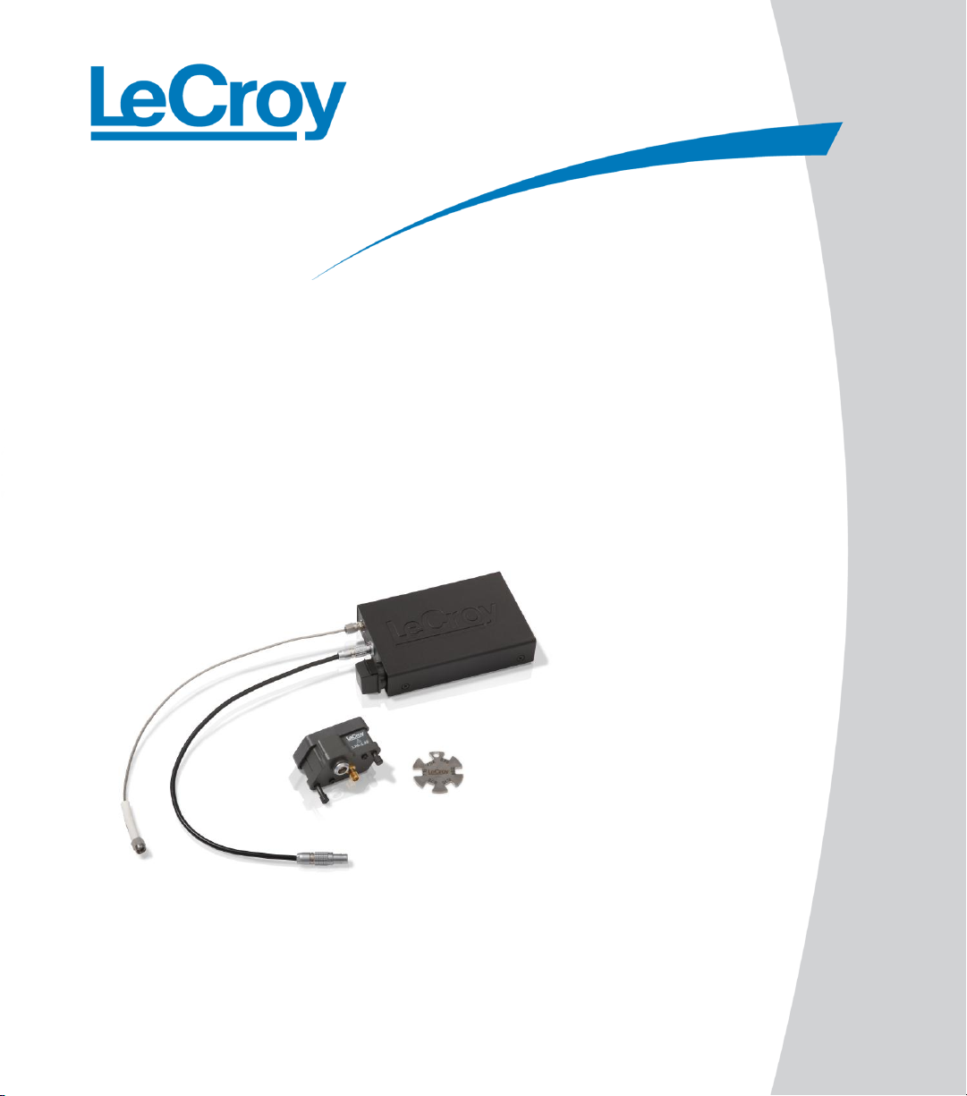
OE695G
Optical to Electrical Converter
Page 2

OE695G Optical to Electrical Converter
Instruction Manual
PRELIMINARY VERSION
Page 3
Manufactured under an ISO 9000
Registered Quality Management System.
Visit www.lecroy.com to view the
certificate.
This electronic product is subject to
disposal and recycling regulations that vary
by country and region. Many countries
prohibit the disposal of waste electronic
equipment in standard waste receptacles.
For more information about proper disposal
and recycling of your LeCroy product,
please visit www.lecroy.com/recycle.
LeCroy Corporation
700 Chestnut Ridge Road
Chestnut Ridge, NY, 10977-6499
Tel: (845) 578-6020, Fax: (845) 578 5985
www.lecroy.com
OE695G Optical to Electrical Converter Instruction Manual
© 2012 LeCroy Corporation. All rights reserved.
Unauthorized duplication of LeCroy documentation materials other than for internal sales and distribution purposes is
strictly prohibited. However, clients are encouraged to distribute and duplicate LeCroy documentation for their own
internal educational purposes.
LeCroy and other product or brand names are trademarks or requested trademarks of their respective holders.
Information in this publication supersedes all earlier versions. Specifications are subject to change without notice.
WARRANTY
LeCroy warrants this oscilloscope accessory for normal use and operation within specification for a period of one year
from the date of shipment. Spare parts, replacement parts and repairs are warranted for 90 days.
In exercising its warranty, LeCroy, at its option, will either repair or replace any assembly returned within its warranty
period to the Customer Service Department or an authorized service center. However, this will be done only if the product
is determined by LeCroy's examination to be defective due to workmanship or materials, and the defect is not caused by
misuse, neglect, accident, abnormal conditions of operation, or damage resulting from attempted repair or modifications
by a non-authorized service facility.
The customer will be responsible for the transportation and insurance charges for the return of products to the service
facility. LeCroy will return all products under warranty with transportation charges prepaid.
This warranty replaces all other warranties, expressed or implied, including but not limited to any implied warranty of
merchantability, fitness or adequacy for any particular purposes or use. LeCroy shall not be liable for any special,
incidental, or consequential damages, whether in contract or otherwise.
OE695G-OM-E Rev A
921024-00 Rev A
Page 4

Instruction Manual
OE695G-OM-E Rev A
i
Declaration of Conformity
According to ISO/IEC Guide 22 and EN 45014:1998
Manufacturer's Name: LeCroy Corporation
Manufacturer's Address: 700 Chestnut Ridge Road, Chestnut Ridge, NY, 10977-6499 USA
herewith declare that
Product(s) Name: Optical to Electrical Converter
Model Number(s): OE695G
including all its options are in conformity with the provisions of the following EC directive(s), including the
latest amendments, and with national legislation implementing these directives:
73/23/EEC Low Voltage Directive
89/336/EEC EMC Directive
and that conformity with Council Directive 73/23/EEC is based on
EN 61010-031: 2002 Safety requirements for electrical equipment for measurement, control and
laboratory use
Part 031: Safety requirements for hand-held probe assemblies for electrical measurement and test
and that conformity with Council Directive 89/336/EEC is based on
EN 61326-1:1997+A1:1998+A2:2001 EMC requirements for electrical equipment for measurement,
control and laboratory use
Emissions: EN 55011:1998+A1:1999 Radiated Emissions
Immunity: EN 61000-4-2:1995+A2:2002 Electrostatic Discharge
EN 61000-4-3:2002 RF Radiated Electromagnetic Field
By: David C. Graef
Chief Technology Officer
700 Chestnut Ridge Road, Chestnut Ridge, NY, 10977-6499
Date: July 2, 2012
Warning: This is a Class A product. In a domestic environment this product may cause radio interference,
in which case the user may be required to take adequate measures.
Page 5

OE695G Optical to Electrical Converter
ii
OE695G-OM-E Rev A
TABLE OF CONTENTS
Declaration of Conformity ............................................................ i
OE695G Overview ....................................................................... 1
Key Features: ............................................................................... 1
Compatibility ............................................................................... 2
Operation ................................................................................... 2
Safety Requirements ................................................................... 2
Operating Environment ............................................................... 3
Connecting the Unit to the Oscilloscope ..................................... 4
Connecting the Unit to the Optical Fiber .................................... 4
Operation with a LeCroy Oscilloscope......................................... 4
Care and Maintenance ................................................................ 7
Cleaning the OE695G ................................................................... 7
Calibration Interval ...................................................................... 7
Service Strategy ........................................................................... 7
Returning a Product for Calibration or Service ........................... 8
Returning a Product to a Different Country ................................ 9
Contact LeCroy for Support ....................................................... 10
Page 6

Instruction Manual
OE695G-OM-E Rev A
1
8GFC (8.5 Gb/s)
10GBASE-W (9.953 Gb/s)
OC192 (STM64) (9.953 Gb/s)
10GBASE-R (10.3125 Gb/s)
10GFC (10.519 Gb/s)
ITU-T G.975 FEC (10.664 Gb/s)
ITU-T G.709 FEC (10.709 Gb/s)
10 GbE FEC (11.096 Gb/s)
10GFC FEC (11.317 Gb/s)
User Defined (up to 11.5 Gb/s)
None (maximum 12.667 Gb/s)*
OE695G Overview
The OE695G is designed to help troubleshoot optical-to-electrical signal integrity issues at the
board level. For system integrators who measure both electrical and optical signals in their
products, the OE695G provides electrical measurements on optical signals, while taking full
advantage of the LeCroy real-time oscilloscope’ tool set and the broad debugging capabilities of
the LeCroy Serial Data and Crosstalk Analysis software options.
When connected to the oscilloscope, the OE695G becomes an integrated part of the
oscilloscope. Power is supplied to the OE695G by the oscilloscope (no external power supply is
needed), and the OE695G communicates to the oscilloscope its identity and scaling information.
The Optical Wavelength, Dark Calibration and Reference Receiver functions are all controlled
from the oscilloscope’s user interface.
The OE695G is unique in that it operates with a real-time oscilloscope, not a sampling
oscilloscope, and uses a digital signal processing (DSP) filter to enable a user-selectable
reference receiver response. Since the optical input signal is input to a real-time oscilloscope, it
is possible to use the contiguous data acquisition of the real-time oscilloscope to obtain serial
data pattern knowledge and provide Tj, Rj, and Dj decomposition to very high accuracy, like
what is done with high-speed electrical serial data signals. The low cost and general purpose
utility of this optical to electrical converter makes it ideal for those who are already using realtime oscilloscopes for electrical serial data measurements, and need to also measure optical
serial data signals as well.
Key Features:
Frequency range DC to 9.5 GHz (electrical, -3 dB)
Selectable reference receiver support from 8 Gb/s FibreChannel (8G FC) to 10 Gb/s
FibreChannel with Forward Error Correction (10G FC FEC), Custom (<11.5 Gb/s).
Selectable settings include:
*Cannot meet reference receiver specification past 9.5 GHz.
Page 7

OE695G Optical to Electrical Converter
2
OE695G-OM-E Rev A
62.5/125 μm multi-mode or single-mode fiber input
Broad wavelength range (750 to 1650 nm)
+7 dBm (5 mW) max peak optical power
Low noise (as low as 25 pW/√Hz)
Compatibility
The OE695G converter is compatible with WaveMaster/SDA/DDA 8 Zi/Zi-A, LabMaster 9
Zi-A, and LabMaster 10 Zi series oscilloscopes using LeCroy’s 2.92mm interface and
LeCroy’s ProLink interface through the use of the LPA-2.92 ProLink to 2.92mm adapter.
Requires 6.9.0.0 or later version of Oscilloscope firmware.
Operation
Safety Requirements
Avoid personal injury or damage to your accessory or any equipment connected to it by
reviewing and complying with the following safety precautions:
Use only as intended. The accessory is intended to be used only with the compatible LeCroy
instruments. Use of the accessory and/or the equipment it is connected to in a manner other than
specified may impair the protection mechanisms.
Connect and disconnect properly. Avoid damage through excessive bending of cables and
other equipment.
Do not use in wet/damp or explosive atmospheres.
For indoor use only. The accessory is intended for indoor use and should be operated in a clean,
dry, environment.
Page 8

Instruction Manual
OE695G-OM-E Rev A
3
Do not operate with suspected failures. Do not use the product if any part is damaged. All
maintenance should be referred to qualified service personnel.
Keep product surfaces clean and dry.
Completely assemble the measurement instrument before circuit/signal contact.
Connect accessory to the measurement instrument before connecting the instrument test leads to
a circuit/signal being tested.
Do not apply a voltage to any input that exceeds the maximum rating of that input.
Refer to the Specifications on LeCroy website at www.lecroy.comfor detailed information.
Operating Environment
The accessory is intended for indoor use and should be operated in a clean, dry environment.
Before using this product, ensure that its operating environment is maintained within these
parameters:
Temperature: 5 to 40 °C.
Humidity: Maximum relative humidity 80 % for temperatures up to 31 °C decreasing linearly to
50 % relative humidity at 40 °C.
Altitude: Up to 10,000 ft (3,048 m).
NOTE: Direct sunlight, radiators, and other heat sources should
be taken into account when assessing the ambient
temperature.
Page 9

OE695G Optical to Electrical Converter
4
OE695G-OM-E Rev A
Connecting the Unit to the Oscilloscope
To connect the optical to electrical converter to the oscilloscope:
1. Attach the OE695G 2.92mm connections to the LeCroy oscilloscope 2.92mm interface.
Use a torque wrench to provide appropriate torque to the connector when tightening.
2. If connecting to a ProLink oscilloscope interface, first connect the LPA 2.92mm ProLink
to 2.92mm adapter to the oscillosocpe, then connect the OE695G to the adapter.
3. Connect the OE695G LEMO connector to the power connection of the oscilloscope
2.92mm interface or the LPA-2.92 adapter. Align the red dot on the cable to the red
mark on the connector.
4. Verify the LEMO power connector is locked to the connection.
5. Connect the other end of the SMA cable to the converter, if not already connected. Use
a torque wrench to ensure proper torque
6. Connect the other end of the LEMO power cable to the optical to electrical converter.
7. To disconnect power, pull on the LEMO connector tip to release the lock and pull out
the LEMO connector.
Connecting the Unit to the Optical Fiber
A plastic cap covers the FC/PC input connector. Carefully remove this cover and insert a fiber
optic cable with a cladding dimension of 125 µm. The core diameter should nominally be 62.5
µm. Other core diameters may be used with the OE695G, but a smaller or larger diameter will
alter the amount of light falling on the photo-receiver and impact the gain accuracy of the
OE695G. Both multi-mode and single-mode fibers may be used with the OE695G provided they
are mechanically compatible.
Operation with a LeCroy Oscilloscope
After the OE695G connectors are attached, the converter can be controlled through the
oscilloscope. Turning the VOLTS/DIV knob will control the oscilloscope’s scale factor to give full
dynamic range in µW/div.
Page 10

Instruction Manual
OE695G-OM-E Rev A
5
Channel Dialog
When the OE695G is connected to a particular channel, the respective Channel dialog will
change to reflect the connection of the device:
An OE695G tab for controlling the converter is added to the Channel dialog (Figure 1)
Gain settings are adjusted and vertical scale labels automatically change to µW/div units
Coupling, bandwidth limit (BWL), and other selections are prohibited since they must be
preset to certain values to allow proper functioning of the OE695G.
Figure 1 shows the oscilloscope user interface menu for the OE695G converter. The dialog
allows for the selection of the converter’s Dark Calibration, Reference Receiver selection and
Optical Wavelength selection functions.
Figure 1: OE695G tab of the oscilloscope’s Channel dialog.
Dark Calibration
The OE695G incorporates a Dark Calibration function to measure the channel offset signal
without any light present in the optical receiver.
To perform the dark calibration, cover the OE695G input with the supplied cap, and press the
Dark Calibration button on the OE695G dialog.
A scale factor value will be calculated and displayed. Dark calibration will vary with temperature
(the dark calibration level variation with temperature is -2 μW/ ºC typical), so if the temperature
varies considerably, additional dark calibrations may be required. After a dark calibration is
performed, the temperature it was performed at will be displayed in the Attributes section of
the OE695G dialog, at the right of the dialog.
Touch Set to Zero to reset the Dark Calibration value to zero.
Page 11

OE695G Optical to Electrical Converter
6
OE695G-OM-E Rev A
8GFC (8.5 Gb/s)
10GBASE-W (9.953 Gb/s)
OC192 (STM64) (9.953 Gb/s)
10GBASE-R (10.3125 Gb/s)
10GFC (10.519 Gb/s)
ITU-T G.975 FEC (10.664 Gb/s)
ITU-T G.709 FEC (10.709 Gb/s)
10 GbE FEC (11.096 Gb/s)
10GFC FEC (11.317 Gb/s)
User Defined (up to 11.5 Gb/s)
None (maximum 12.667 Gb/s)*
Reference Receiver
The OE695G contains optional, built-in software reference receiver filters for common Fiber
Channel, Ethernet, and ITU telecom standards. These reference receiver filters provide a 4-pole
Bessel Thompson low pass filter response for the combined oscilloscope and optical-to-electrical
(O-E) system with the -3dBe (electrical) power at 0.75* bitrate.
Available reference receiver filters include:
The software reference receiver supplied standard with the OE695G is based on a “nominal”
oscilloscope response. The typical uncertainty in this standard reference receiver frequency
response is ±1.6 dBe up to Fref =0.75*bit rate and ±4 dBe 2*bitrate setting.
An OE695G-REFCAL OE695G reference receiver calibration can be purchased that will provide
less uncertainty with the OE695G when used with a specific oscilloscope and a specific channel.
This REFCAL would usually be purchased at the time of initial OE695G and oscilloscope
purchase. If this is the case, then LeCroy will calibrate the specific OE695G to a specific serial
number oscilloscope channel (channel 4 unless otherwise specified) and the resultant reference
receiver uncertainty will be ±0.85 dBe up to Fref =0.75*bit rate, and ±4 dBe 2*bit rate setting
on the specified oscilloscope input channel on the 11, 17, 20, 30, 39, 50, 75, 90, or 100 mV/div
gain ranges. The calibration will be indicated in the dialog box, as indicated above. Multiple
OE695G can be calibrated to unique oscilloscope channels to allow usage of multiple OE695G.
NOTE: If the OE695G-REFCAL is purchased after initial the
OE695G/oscilloscope purchase, the oscilloscope must be
returned to LeCroy for the OE695G-REFCAL to be performed.
A custom reference receiver (User Defined) can be applied for any bit rate up to 11.5 Gb/s. Bit
rates up to 12.5 Gb/s bit rates may be specified, but beyond 11.5 Gb/s, the reference receiver
requirements cannot be maintained.
Page 12

Instruction Manual
OE695G-OM-E Rev A
7
Input Selection for Optical Wavelength
There are four standard optical wavelength selections at 785nm, 850nm, 1310nm and 1550nm.
Custom optical wavelength can be adjusted between 750nm to 1650nm; however, gain of the
OE695G can vary widely at different wavelengths, and calibration of gain is only performed at
the standard wavelengths. At other wavelengths, gain is assumed to follow a linear slope, but
this assumption will not yield the stated vertical level power accuracy specification. However,
the overall signal fidelity will still be maintained.
Care and Maintenance
Cleaning the OE695G
The exterior of the converter should be cleaned with a soft cloth moistened with either water or
75% isopropyl alcohol solution only. Under no circumstances should moisture be allowed to
penetrate the converter.
The fiber connector can be cleaned by blowing residue-free air into the connector to remove
loose particles. A cleaning cloth tape specifically made for fiber cleaning may also be used by
first removing the FC universal connector adapter from the front panel to expose the internal
fiber interface.
Calibration Interval
The recommended calibration interval is one year. Adjustment should be performed only by
qualified personnel.
Service Strategy
Defective products must be returned to a LeCroy service facility for diagnosis and repair or
replacement. Defective products under warranty are repaired or replaced.
Before returning a product as defective, perform the following troubleshooting procedures:
Verify the LeCroy oscilloscope is running firmware 6.9.0.0 or higher. To verify the
Check the power connector is plugged in and locked, and the SMA cable is connected.
firmware version of your oscilloscope, choose Utilities > Utilities Setup from the menu
bar, then touch the Status tab.
Page 13

OE695G Optical to Electrical Converter
8
OE695G-OM-E Rev A
Returning a Product for Calibration or Service
Return a product for calibration or service by contacting your local LeCroy sales representative.
They will tell you where to return the product. All returned products should be identified by
both model and serial number. Provide your name, a contact number, and a description of the
defect or failure (if possible).
Products returned to the factory require a Return Material Authorization (RMA), which can be
acquired by contacting your nearest LeCroy sales office, representative, or the North America
Customer Care Center.
NOTE: It is important that the RMA be clearly shown on the
outside of the shipping package for prompt redirection to the
appropriate department.
Return shipments should be prepaid. LeCroy cannot accept COD or Collect Return shipments.
We recommend air-freighting.
Follow these steps for a smooth product return.
1. Contact your local LeCroy sales or service representative to obtain a Return
Authorization Number.
2. Remove all accessories from the device. Do not include the manual.
3. Pack the product in its case, surrounded by the original packing material (or equivalent)
and box.
4. Label the case with a tag containing:
The RMA
Name and address of the owner
Product model and serial number
Description of failure
5. Package the product case in a cardboard shipping box with adequate padding to avoid
damage in transit.
Page 14

Instruction Manual
OE695G-OM-E Rev A
9
6. Mark the outside of the box with the shipping address given to you by the LeCroy
representative; be sure to add the following:
ATTN: <RMA assigned by the LeCroy representative>
FRAGILE
7. Insure the item you're returning (for at least the replacement cost).
8. Ship the package to the appropriate address.
Returning a Product to a Different Country
NOTE: Be sure to properly mark shipments returned for service
from a different country to avoid customs duty for a full
purchase price of a new accessory.
In addition to the items mentioned in the previous topic, mark shipments returned for service as
a Return of US manufactured goods for warranty repair/recalibration. If there is a cost
involved in the service, put the cost of the service in the value column and the original value of
the product at time of purchase in the body of the invoice marked For insurance purposes only.
Be very specific as to the reason for shipment. Duties may have to be paid on the value of the
service.
Page 15

OE695G Optical to Electrical Converter
10
OE695G-OM-E Rev A
Contact Your Local LeCroy Office for Sales and Technical Assistance
United States and Canada - World Wide Corporate Office
LeCroy Corporation
700 Chestnut Ridge Road
Chestnut Ridge, NY, 10977-6499
Phone: 800-553-2769 (Sales opt. 1, Applications opt. 2, Service opt. 3) or 845-425-2000
Fax: 845-578-5985
Email: contact.corp@lecroy.com
Web:www.lecroy.com
United States - Protocol Solutions Group
LeCroy Corporation
3385 Scott Boulevard
Santa Clara, CA, 95054
Fax: 408-727-0800
Web:www.lecroy.com
Sales and Service:
Phone: 800-909-7211 or 408-727-6600
Email: contact.corp@lecroy.com
Support:
Phone: 800-909-7112 or 408-653-1260
Email: psgsupport@lecroy.com
European Headquarters
LeCroy Europe
4, Rue Moïse Marcinhes
Case postale 341
1217 Meyrin 1
Geneva, Switzerland
Phone: + 41 22 719 2228, +41 22 719 2323,
+41 22 719 2277
Email: contact.sa@lecroy.com,
applications.indirect@lecroy.com
Fax: +41 22 719 2233
Web: www.lecroy.com/europe
Protocol Analyzers: +44 12 7650 3971
China, Mainland
LeCroy Corporation
Beijing Office and Service Center
Rm. 2001 - Office; Rm. 2002 - Service Center
Unit A, Horizon Plaza
No. 6, Zhichun Road, Haidian District
Beijing 100088, R.O.C.
Phone: ++86 10 8280 0318 / 0319 / 0320
Service: ++86 10 8280 0245
Fax: +86 10 8280 0316
Web: www.lecroy.com.cn
China, Taiwan
LeCroy Technology Co Ltd.
Far East Century Park, C3, 9F
No. 2, Chien-8th Road
Chung-Ho City
Taipei Hsien, Taiwan, R.O.C.
Phone: ++ 886 2 8226 1366
Fax: ++ 886 2 8226 1368
Email: sales_twn@lecoln.com.tw
Web: www.lecoln.com.tw
Contact LeCroy for Support
Whether you're looking for sales or technical support, our staff can provide assistance with
installation, calibration, and product knowledge regarding a full-range of our software
applications and accessories.
Page 16

Instruction Manual
OE695G-OM-E Rev A
11
Contact Your Local LeCroy Office for Sales and Technical Assistance
Singapore (Oscilloscopes)
LeCroy Singapore Pte Ltd.
Blk 750C Chai Chee Road #02-08
Technopark@ Chai Chee
Singapore 469003
Phone: ++ 65 64424880
Fax: ++ 65 64427811
Singapore (Protocol Analyzers)
Genetron Singapore Pte Ltd.
37 Kallang Pudding Road, #08-08
Tong Lee Building Block B
Singapore 349315
Phone: ++ 65 9760-4682
Korea - Seoul
LeCroy Korea
10th fl.Ildong Bldg.
968-5 Daechi-dong, Gangnam-gu
Seoul 135-280, Korea
Phone: ++ 82 2 3452 0400
Fax: ++ 82 2 3452 0490
Web: www.lecroy.co.kr
Japan - Tokyo
LeCroy Japan
Hobunsya Funchu Bldg, 3F
3-11-5, Midori-cho, Fuchu-Shi
Tokyo, 183-0006, Japan
Phone: ++ 81 4 2402 9400
Fax: ++ 81 4 2402 9586
Web: www.lecroy.com/japan
Page 17

OE695G Optical to Electrical Converter
12
OE695G-OM-E Rev A
 Loading...