

Page 1
LLeeCCrrooyy
M
M
S
S--550000
M
Mii
x
xee
d
d
S
Sii
g
g
n
naall
O
Osscciillll
o
osscc
o
o
p
pee
O
O
p
pttii
o
o
n
n
O
Oppeerraattoorr’’ss
M
Maannuuaall
JJuunnee,, 2200009
9
Page 2
2 ISSUED: June, 2009 MS-500-OM-E Rev C
LeCroy Corporation
700 Chestnut Ridge Road
Chestnut Ridge, NY 10977–6499
Tel: (845) 578 6020, Fax: (845) 578 5985
Internet: www.lecroy.com
© 2009 by LeCroy Corporation. All rights reserved.
LeCroy, ActiveDSO, WaveLink, JitterTrack, WavePro, WaveMaster, WaveSurfer, WaveExpert, and
Waverunner are registered trademarks of LeCroy Corporation. Other product or brand names are
trademarks or requested trademarks of their respective holders. Information in this publication
supersedes all earlier versions. Specifications subject to change without notice.
Manufactured under an ISO 9000
Registered Quality Management System
Visit www.lecroy.com to view the
certificate.
This electronic product is subject to
disposal and recycling regulations
that vary by country and region.
Many countries prohibit the
disposal of waste electronic
equipment in standard waste
receptacles.
For more information about proper
disposal and recycling of your
LeCroy product, please visit
www.lecroy.com/recycle.
MS-500-OM-E Rev C
917368-00 Rev A
Page 3

MS-500-OM-E Rev C ISSUED: June, 2009 3
TABLE OF CONTENTS
SAFETY REQUIREMENTS ..................................................................................5
Cleaning ........................................................................................................................................... 5
Use and Maintenance ...................................................................................................................... 5
INTRODUCTION ...................................................................................................6
Overview .......................................................................................................................................... 6
Warranty ........................................................................................................................................... 6
Returning a Product for Service or Repair ....................................................................................... 7
Technical Support ............................................................................................................................. 7
Staying Up-to-Date ........................................................................................................................... 7
STANDARD AND ACCESSORY EQUIPMENT ...................................................8
The MS-500 Standard Hardware ..................................................................................................... 8
The MS-500 Software ...................................................................................................................... 9
Accessories .................................................................................................................................... 10
DESCRIPTION OF OPERATION........................................................................ 12
GETTING STARTED WITH THE MS-500 ........................................................... 13
Overview ........................................................................................................................................ 13
Connecting the MS-500 System to the Oscilloscope ..................................................................... 13
Verifying Proper MS-500 Connection to your Oscilloscope and the Device Under Test ............... 16
If you are concerned that your digital signals aren’t being displayed correctly, it is a good idea to
check by viewing the digital signals one at a time with an analog channel. This can point out
errors in your connection or in your logic threshold setup. ............................................................ 16
The Complete System Connection ................................................................................................ 16
Digital Connections ........................................................................................................................ 16
Channel Groupings ................................................................................................................. 17
Connector Colors .................................................................................................................... 17
Standard Output Connection .................................................................................................. 17
Threshold Levels ............................................................................................................................ 17
Minimum voltage swing .................................................................................................................. 19
Basic Oscilloscope Operation ........................................................................................................ 19
ACCESSING THE MS-500 OSCILLOSCOPE MIXED SIGNAL OPTION
TOOLSET ........................................................................................................... 20
Overview ........................................................................................................................................ 20
Oscilloscope Analog Trigger and MS-500 Digital Trigger .............................................................. 20
Digital Trace Groups....................................................................................................................... 21
DIGITAL TRACE GROUP SETUP...................................................................... 23
Digital Trace Group Dialog ............................................................................................................. 23
Digital Logic Threshold Setup ........................................................................................................ 25
Overview ................................................................................................................................. 25
Page 4

MS-500 Mixed Signal Oscilloscope Option
4 ISSUED: June, 2009 MS-500-OM-E Rev C
Digital Logic Setup .................................................................................................................. 26
DIGITAL TRIGGER SETUP ............................................................................... 28
Overview ........................................................................................................................................ 28
Creating a Pattern Trigger .............................................................................................................. 28
Logic Pattern Trigger Setup ........................................................................................................... 29
Logic Bus Trigger Setup ................................................................................................................. 30
Digital Logic Threshold Setup ........................................................................................................ 30
CHARACTERIZE DIGITAL OR MIXED SIGNAL SYSTEM PERFORMANCE ... 32
Overview ........................................................................................................................................ 32
Using Cursors................................................................................................................................. 32
Using Measurement Parameters ................................................................................................... 33
Measurement Gating ...................................................................................................................... 33
Using Statistics and Graphing ........................................................................................................ 34
ISOLATE AND ANALYZE SIGNAL ACTIVITY .................................................. 35
Capture Long Pre-Trigger Time ..................................................................................................... 35
Zooming on Your Waveforms ......................................................................................................... 36
APPENDIX A – SPECIFICATIONS .................................................................... 38
CERTIFICATIONS .............................................................................................. 39
CE Declaration of Conformity ......................................................................................................... 39
EMC Directive ................................................................................................................................ 39
Electromagnetic Emissions: ........................................................................................................... 39
Electromagnetic Immunity: ..................................................................................................... 39
Low-Voltage Directive .................................................................................................................... 39
Page 5
MS-500-OM-E Rev C ISSUED: June, 2009 5
SAFETY REQUIREMENTS
This symbol may appear on the product:
This refers you to additional information contained in the operator’s manual. The corresponding
information in this manual is similarly denoted.
Before using this product, ensure that its operating environment will be maintained within these
parameters:
Temperature:
5 to 40 oC
Humidity:
Maximum relative humidity 80 % (noncondensing) for temperatures up to 31 oC
decreasing linearly to 50 % relative
humidity at 40 oC
Altitude:
Up to 2,000 m
CAUTION
To avoid personal injury or damage to the MS-500 or any equipment connected to it, review and
comply with the following safety precautions.
Use only as intended. Use of the MS-500 and/or the equipment it is connected to in a
manner other than specified may impair the protection mechanisms.
Connect and disconnect properly. Avoid damage to cables thru excessive bending.
Do not use in wet/damp or explosive atmospheres.
For indoor use only. The MS-500 is intended for indoor use and should be operated in a
clean, dry, environment.
Do not operate with suspected failures. Do not use MS-500 if any part is damaged. All
maintenance should be referred to qualified service personnel.
Keep product surfaces clean and dry.
Cleaning
The outside of the MS-500 hardware should be cleaned with a soft cloth dampened with either
deionized / distilled water or isopropyl alcohol. Allow the surface to dry completely before
returning the instrument to service.
Use and Maintenance
The MS-500 is a high quality, precision instrument. To maintain accuracy and signal fidelity,
mechanical shock should be avoided, as well as damage to the cables through excessive
bending. All maintenance and component replacement should be referred to qualified personnel.
Page 6

MS-500 Mixed Signal Oscilloscope Option
6 ISSUED: June, 2009 MS-500-OM-E Rev C
INTRODUCTION
Overview
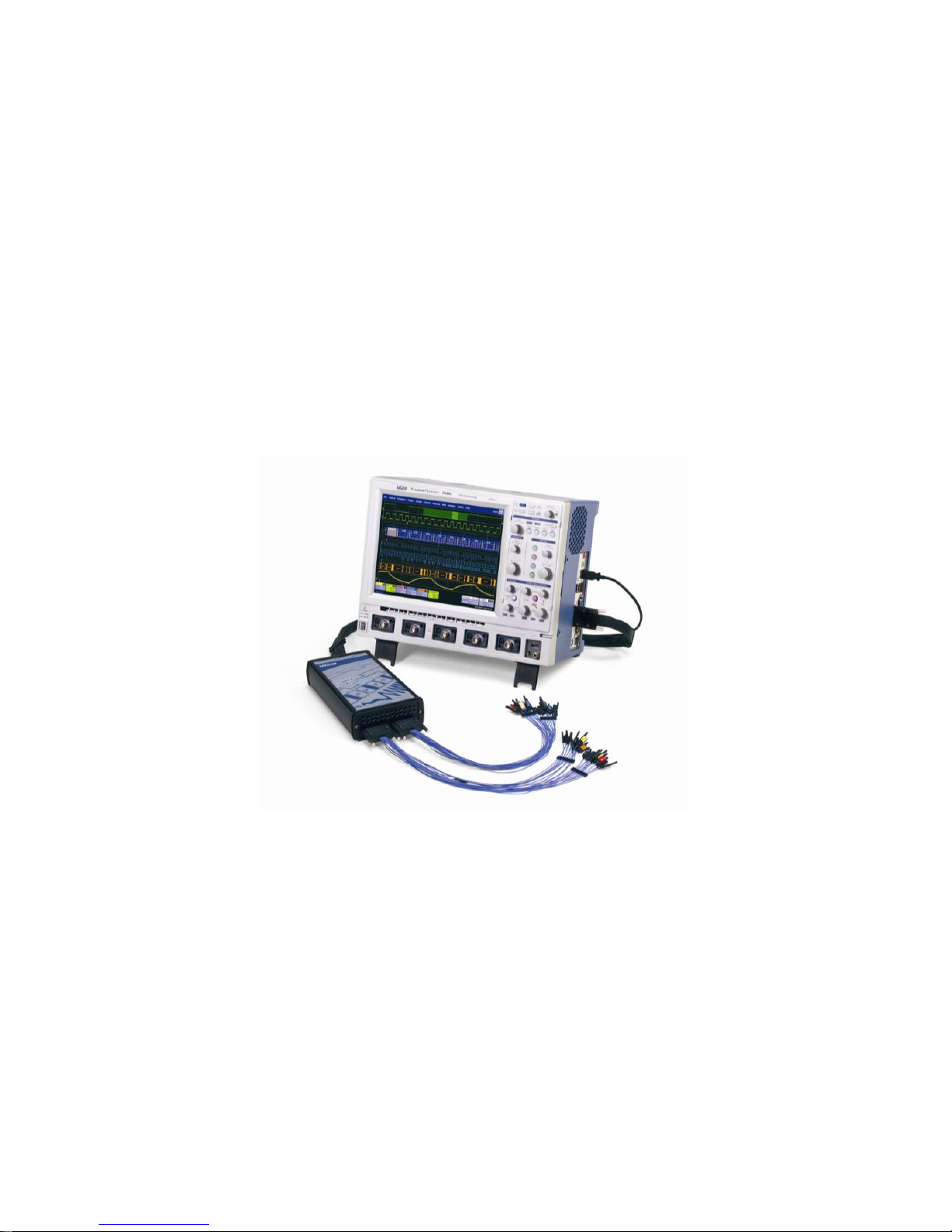
The MS-500 Mixed Signal Oscilloscope Option is a powerful solution for the challenge of
measuring multiple, mixed signals in a single oscilloscope. An enhancement tool to the LeCroy
WaveRunner Xi Series and WaveSurfer Xs Series oscilloscopes, the MS-500 extends their
testing range by adding 18 or 36 digital channels for display or triggering.
The MS-500 is ideally suited for embedded controller testing where there is a proliferation of
analog signals (comparators, voltage sources, sensor/actuator signals, etc.) coincident with digital
signals (address or data lines, control signals, or peripheral serial data signals). Users can easily
debug signals using standard oscilloscope tools such as cursors, measurement parameters, and
zooming.
Both oscilloscopes usable with the MS-500 feature large, bright color displays to facilitate signal
viewing, plus all the connectivity and documentation capabilities needed to quickly record and
distribute information.
This MS-500 manual assumes that you have a basic understanding of discrete electronics, logic
analyzers, and LeCroy oscilloscopes, specifically the LeCroy oscilloscope that the MS-500
system will be used with. When practical or necessary there are details on specific oscilloscope
features included in this manual.
The MS-500 and MS-500-36 are identical except the MS-500-36 standard configuration is for 36
channels. The MS-500-36 can be operated in 36 or 18 channel mode for higher performance.
The MS-500 is configured as an 18 channel instrument and can be upgraded with an additional
lead set to support 36 channels.
In this manual the MS-500 and MS-500-36 are referred to solely as MS-500.
Warranty
The MS-500 is warranted for normal use and operation, within specifications, for a period of one
year from shipment. LeCroy will either repair or, at our option, replace any product returned to
one of our authorized service centers within this period. However, in order to do this we must first
examine the product and find that the defect is due to workmanship or materials and not due to
misuse, neglect, accident, or abnormal conditions or operation.
LeCroy shall not be responsible for any defect, damage, or failure caused by any of the following:
a) attempted repairs or installations by personnel other than LeCroy representatives, or b)
improper connection to incompatible equipment, or c) for any damage or malfunction caused by
the use of non-LeCroy supplies.
Spare and replacement parts, and repairs, all have a 90-day warranty.
The oscilloscope’s firmware has been thoroughly tested and is presumed to be functional. This
includes MS-500 specific firmware. Nevertheless, it is supplied without warranty of any kind
covering detailed performance. Products not made by LeCroy are covered solely by the warranty
of the original equipment manufacturer.
Page 7

MS-500-OM-E Rev C ISSUED: June, 2009 7
Returning a Product for Service or Repair
If you suspect that you have a problem with the MS-500 you should first contact your local
LeCroy service center so they can ascertain whether the component is defective.
If you need to return a LeCroy product, provide model identification by providing the model name
and serial number, describe the defect or failure, and give us your name and telephone number.
For factory returns, use a Return Authorization Number (RAN), which you can get from customer
service. Write the number clearly on the outside of the shipping carton. Return products requiring
only maintenance to your local customer service center. Within the warranty period,
transportation charges to the service center are your responsibility.
Products under warranty are then returned to you with transport prepaid by LeCroy. Outside the
warranty period, you provide us with a purchase order number before the work can be done. You
are also billed for parts and labor related to the repair work and shipping. It is highly
recommended to prepay return shipments and use air freight.
It is highly recommended to prepay return shipments and use air freight. LeCroy cannot accept
COD (Cash On Delivery) or Collect Return shipments.
Technical Support
You can get assistance with installation and operation from your customer service center. Visit
the LeCroy Web site at http://www.lecroy.com for the center nearest you.
Staying Up-to-Date
Your MS-500 hardware does not need periodic calibration.
LeCroy offers state-of-the-art performance by continually refining and improving the instrument’s
capabilities and operation. We frequently update both firmware and software during service, free
of charge during warranty. Therefore, MS-500 specific software may be periodically updated. You
can download firmware and software updates from the LeCroy website.
Since software is continuously updated, the dialog boxes and menus you see in your program
may be slightly different than what is shown in this manual. These differences should not affect
your understanding of correctly operating the MS-500.
Page 8
MS-500 Mixed Signal Oscilloscope Option
8 ISSUED: June, 2009 MS-500-OM-E Rev C
STANDARD AND ACCESSORY EQUIPMENT
The MS-500 Standard Hardware
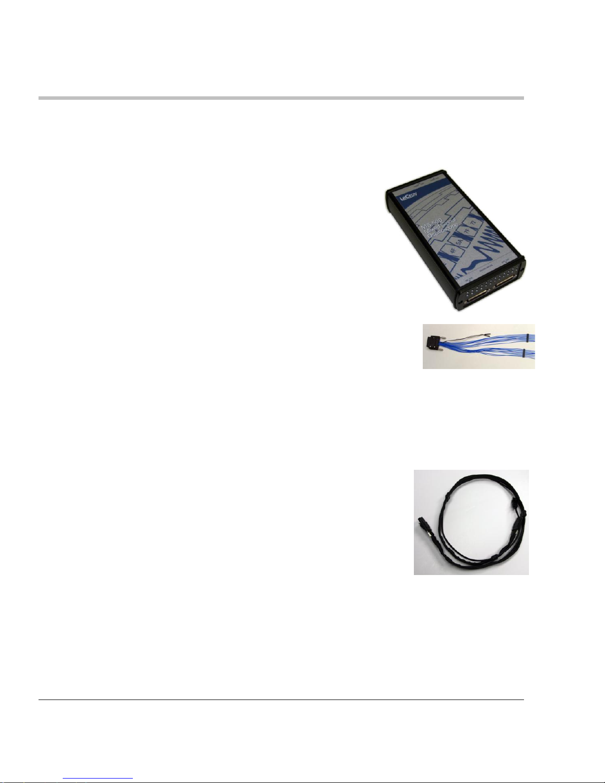
The Standard Hardware consists of the following items:
Qty. 1 Mixed Signal Oscilloscope Option – Provides 18
or 36 channel digital acquisition and triggering.
Qty. 1 16” (40.64 cm) Digital Lead Set – Interfaces the
MS-500 to the device under test. The lead set terminates
in a 25 mil pin socket. Micro-gripper probes of various
sizes are available as accessories from LeCroy, and may
be connected to the lead set. (Qty.2 provided with MS500-36)
The lead set is divided into two groups. Each lead within
the group is color-coded (to resistor color-coding standard)
and has an individual ground connection. In addition, there
are two common ground leads available for use.
Qty. 1 LeCroy Bus Cable – 1.3m cable to connect Mixed
Signal Hardware to main oscilloscope unit, includes
USB2.0 cable. This connection provides timebase
synchronization, cross-triggering and power.
Page 9
MS-500-OM-E Rev C ISSUED: June, 2009 9
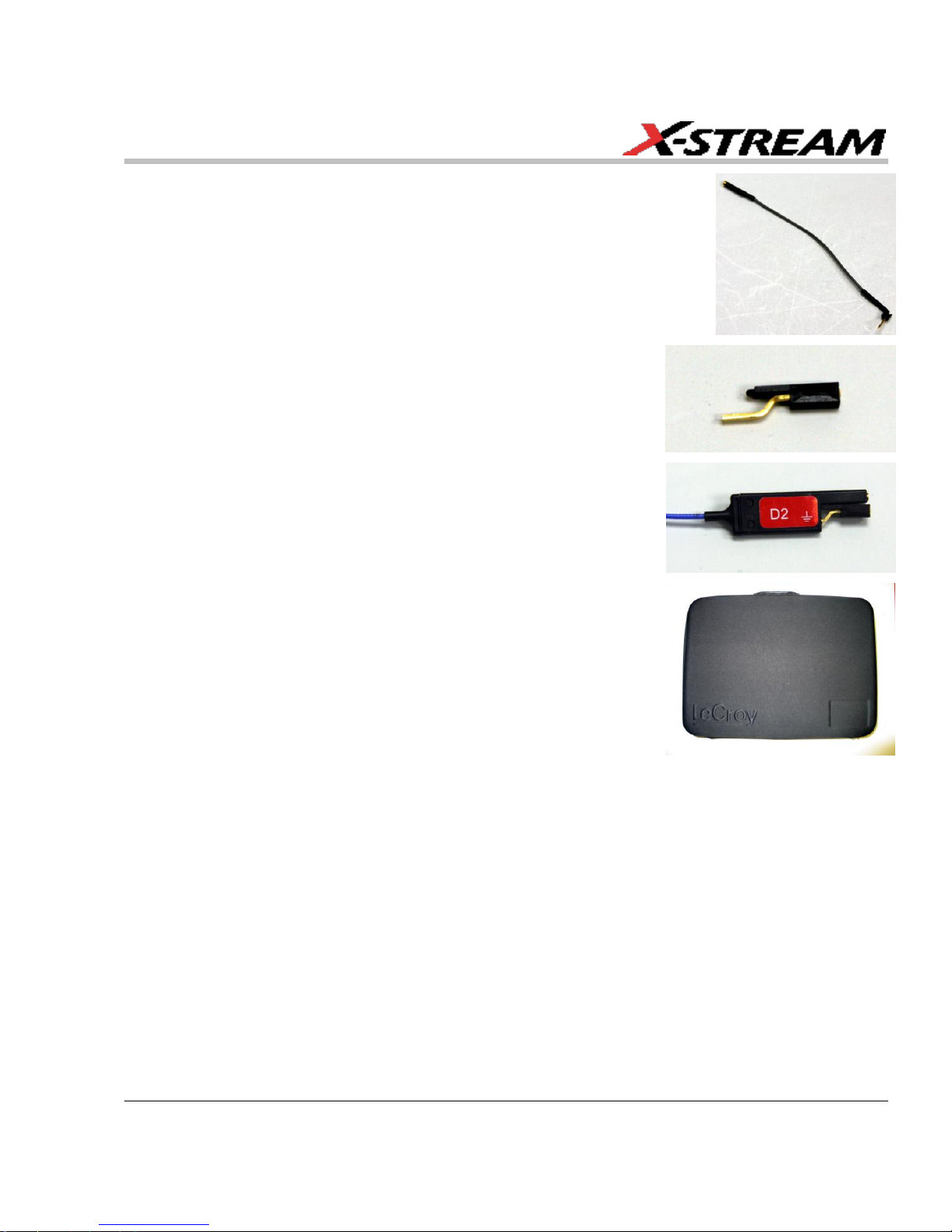
Qty. 5 3” Flexible Ground Lead – Lead for grounding
individual digital inputs (Qty. 10 for MS-500-36)
Qty. 20 Ground Extender – Connect to ground port of any
digital input and make a simple signal and ground
connection to a 0.1”square pin header. (Qty. 40 with MS500-36)
Qty. 1 Carrying Case
Qty. 1 Quick Reference Guide
Qty. 1 Operator’s Manual
The MS-500 Software
The standard MS-500 software adds the following capability to the LeCroy oscilloscope software
dialogs:
Analog, Digital and Combination Trigger Modes – Allows you to choose whether to set
an analog trigger condition, a digital trigger condition or a pattern consisting of analog
and digital signals.
Digital Trigger – Allows a digital trigger condition to be set from within the oscilloscope
using an easy-to-understand interface.
Digital Channels – Provides a standard, general purpose setup for defining the digital
channels and displaying digital lines.
Page 10
MS-500 Mixed Signal Oscilloscope Option
10 ISSUED: June, 2009 MS-500-OM-E Rev C
Digital Threshold Setup – Provides the means to define a logic threshold for digital
trace calculation.
The MS-500 Hardware and Software requires no traceable calibration or adjustment. However,
the oscilloscope used with the MS-500 does require periodic calibration and adjustment.
Accessories
The following accessories are also available for use with the MS-500.
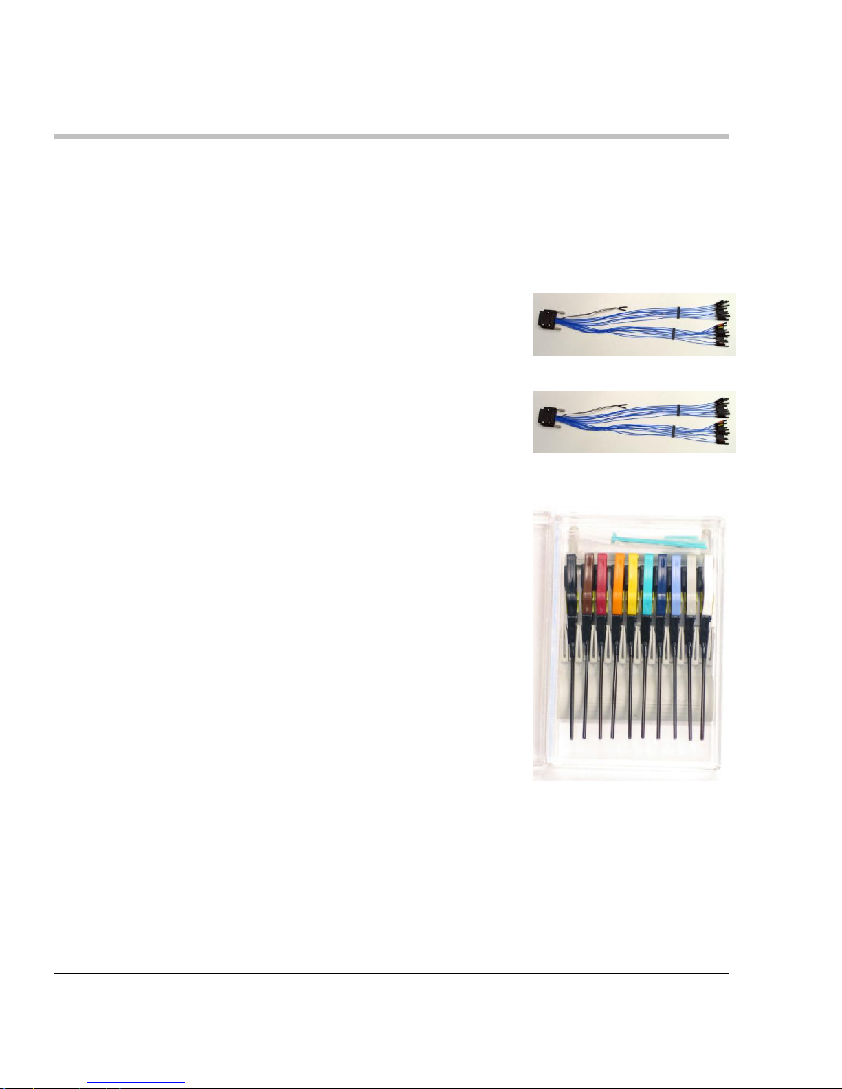
MSO-DLS-18 16” (40.64 cm) Digital Lead Set – You may
find an additional standard digital lead set convenient if
you have more than one device under test and do not wish
to disconnect/reconnect your cables (when using the MS500 on different DUTs). Inputs are labeled D0 – D17.
MSO-DLS-36 16” (40.64 cm) Digital Lead Set – An
additional digital lead set. This might be convenient to
have if you have more than one device under test and do
not wish to disconnect/reconnect your cables to use the
MS-500 on different DUTs. Adding this to the MS-500
enables 36 channels. Inputs are labeled D18 – D35
PK400-1 – Large gripper probe set for 0.10 inch (2.54
mm) pin pitch. Includes 10 probes with color-coded leads.
Page 11
MS-500-OM-E Rev C ISSUED: June, 2009 11
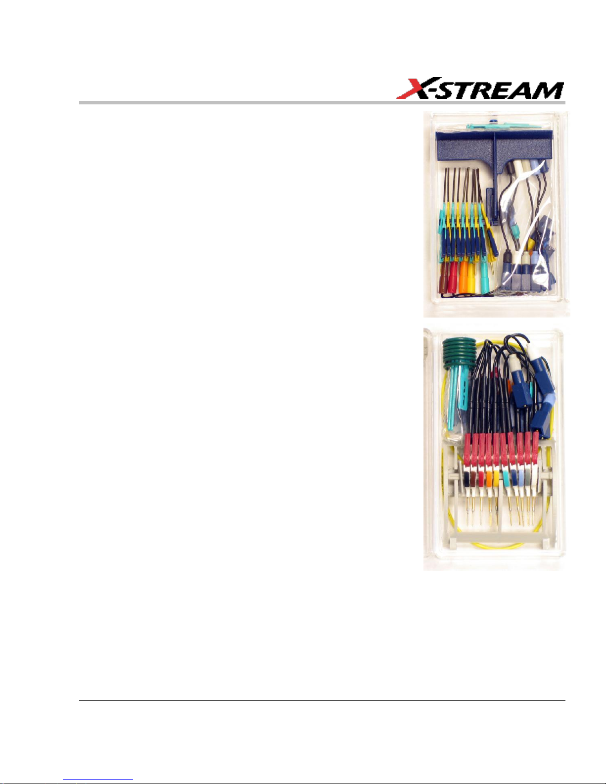
PK400-2 – Medium gripper probe set for 0.04 inch (1.0
mm) pin pitch. Includes 10 probes with color-coded leads.
PK400-3 – Small gripper probe set for 0.008 inch (0.2
mm) pin pitch. Includes 10 probes with color-coded leads.
MSO-MICTOR – Mictor Connection cable, 16” (40.64 cm),
36 channel connector.
MSO-3M - Interconnect cable, 16” (40.64 cm) mates with
3M connectors, 2520-6002 and 25205002.
Page 12

MS-500 Mixed Signal Oscilloscope Option
12 ISSUED: June, 2009 MS-500-OM-E Rev C
DESCRIPTION OF OPERATION
The various components of the MS-500 Mixed Signal Oscilloscope Option acquire and store
digital data, trigger on digital patterns, interface the external module to the oscilloscope, and
provide a user-friendly interface for control and interpretation of data.
The MS-500 is an external device that digitally samples waveform data at up to 2 GS/s (for 500
MHz digital signals). Unlike a logic analyzer, it operates only in a Timing Analysis mode, so it
requires 4x oversampling to determine the correct digital edge position, and does not require the
user to input a clock.
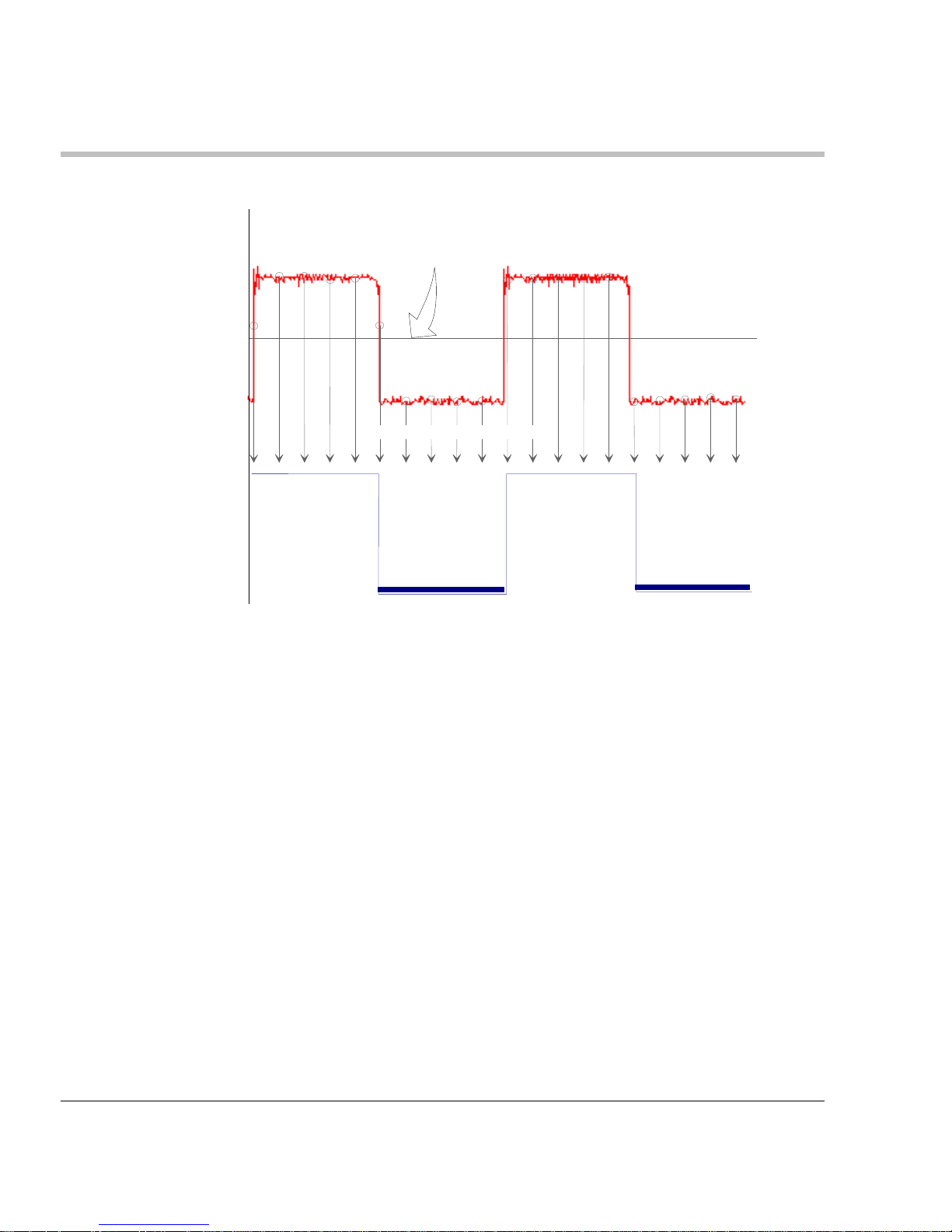
While in SINGLE, NORMAL, or AUTO trigger mode, the MS-500 repeatedly samples each digital
channel’s voltage level. If the voltage is greater than the threshold voltage, the MS-500 stores a 1
in internal memory. Otherwise, a 0 is stored.
1
Threshold level
1 1 1 1 1 0 0 0 0 1 1 1 1 1 0 0 0 0 0
The minimum high voltage level is user definable by the hysteresis control up to 1.4 V above the
threshold. The maximum low voltage level is user definable by the hysteresis control up to 1.4 V
below the threshold. The minimum signal swing is 100 mV. The indeterminate range of 50 mV
around the threshold voltage level is the level below which the MS-500 will not operate. However,
the MS-500 can support a signal as low as 100 mV only if the input signal’s quality is adequate.
The MS-500 keeps sampling its inputs until the oscilloscope is put into STOP trigger mode. Data
is stored in a 50 Mpt internal memory that is periodically transferred to the oscilloscope via the
USB2.0 cable. If the oscilloscope is triggering in SINGLE or NORMAL trigger mode, data is
acquired and transferred only when the trigger condition is satisfied. The captured data is then
displayed on the oscilloscope grid in a time-aligned fashion.
In any trigger mode (AUTO, NORMAL, SINGLE), pressing STOP trigger cancels the acquisition,
which leaves the previously acquired data unchanged.
The MS-500 both samples incoming data and searches for trigger conditions.
The USB2.0 cable provides downloading of trigger conditions from the oscilloscope to the MS-
500 and uploading of digital data from the MS-500 to the oscilloscope.
Page 13

MS-500-OM-E Rev C ISSUED: June, 2009 13
GETTING STARTED WITH THE MS-500
Overview
The MS-500 is a complete system that interfaces with the oscilloscope in a number of ways that
make it easier to do the following:
Set analog, digital and combination triggers.
View all analog and digital signal information on the oscilloscope grid, with all signals
time-correlated
All setup is done in the user-friendly oscilloscope dialogs – it is not required to leave the
oscilloscope software to run the MS-500. All normal oscilloscope tools (cursors, measurement
parameters, etc.) are available for use with the digital signals.
There are physical connections that must be made to ensure proper operation, but the intuitive
connection steps are documented here.
Operation of the WaveRunner or WaveSurfer oscilloscope is not covered in this manual.
Reference the On-Line Help or Getting Started Manual for each oscilloscope for complete
information on analog triggering, display of analog signals, front panel operation, etc.
Connecting the MS-500 System to the Oscilloscope
Connect the MS-500 System to the Oscilloscope as follows:
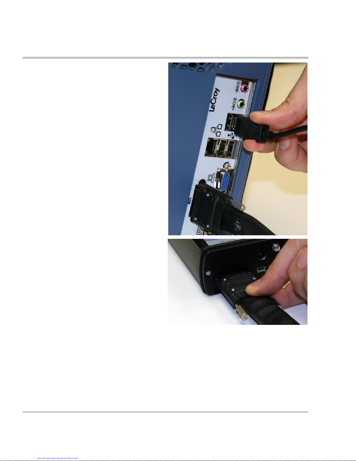
1. Connect the LeCroy Bus Cable to the
LeCroy Bus connector on the side of
the oscilloscope and fasten the thumb
screws.
Page 14
MS-500 Mixed Signal Oscilloscope Option
14 ISSUED: June, 2009 MS-500-OM-E Rev C
2. Connect the USB 2.0 cable (attached
to the LeCroy Bus cable) to any of the
side mounted USB ports on the
oscilloscope.
3. Connect the other end of the LeCroy
Bus cable to the MS-500 and fasten
the thumb screws.
Page 15

MS-500-OM-E Rev C ISSUED: June, 2009 15
4. Connect the other end of the USB2.0
Cable to the MS-500.
5. Connect the Digital Lead Set to the
other end of the MS-500 (labeled
Digital Inputs, D0 – D17) and fasten
the thumb screws. For MS-500-36
repeat this process with the lead set
labeled D18 – D35.
6. Note that each digital line has a
ground connection for optimal
performance. Two additional ground
leads common to the whole lead set
are also available.
Connect the Digital Leads to the digital
lines you wish to observe (using
accessory micro-grippers, as
necessary or desired).
7. Turn on power to the oscilloscope and
wait for the oscilloscope application to
begin.
Page 16

MS-500 Mixed Signal Oscilloscope Option
16 ISSUED: June, 2009 MS-500-OM-E Rev C
Verifying Proper MS-500 Connection to your Oscilloscope and the Device Under Test
If you are concerned that your digital signals aren’t being displayed correctly, it is a good idea to
check by viewing the digital signals one at a time with an analog channel. This can point out
errors in your connection or in your logic threshold setup.
The Complete System Connection
When your system is connected properly it looks like the following photo:
It is usually easiest to debug digital line connection or display problems by viewing the digital
information on an analog channel to confirm its presence, then working back through the previous
sequence to determine where the connection or display error is.
Digital Connections
Handle with care!
The MS-500 Digital Lead Set connectors are fragile. Pull the
connector base, not the wire. Never bend the connectors.
Page 17

MS-500-OM-E Rev C ISSUED: June, 2009 17
Channel Groupings
The 18 channels in the lead set are divided into two physical groups of 9 and each group is
bundled with a plastic separator. When using 36 channels there are 4 groups of 9 leads
Note: The grouping you assign to the digital lines in the software interface can be different than the physical grouping of
digital lines. The physical grouping is intended for easy identification of all 18 digital lines.
Connector Colors
The wires in each color group use 9 repeating colors.
The color sequence corresponds to the resistor color code making it easier to know the digital line
number without having to look at the label.
Standard Output Connection
The standard terminations on the digital lead sets can be pushed directly onto 25-mil pins.
MicroGrippers or NanoGrippers may also be used to probe the test circuit’s pins. LeCroy provides
a selection of small, medium, and large grippers for various pitch sizes. A more complete
selection of adapter probes is available for most chips from Emulation Technology Inc., Yamaichi
Inc., and other manufacturers.
Threshold Levels
The threshold level determines how the input signal is interpreted. The threshold level can be set
in either the Digital Grouping Setup or Pattern Trigger Setup dialogs (it is the same setup, but is in
two different places for operator convenience).
Page 18
MS-500 Mixed Signal Oscilloscope Option
18 ISSUED: June, 2009 MS-500-OM-E Rev C
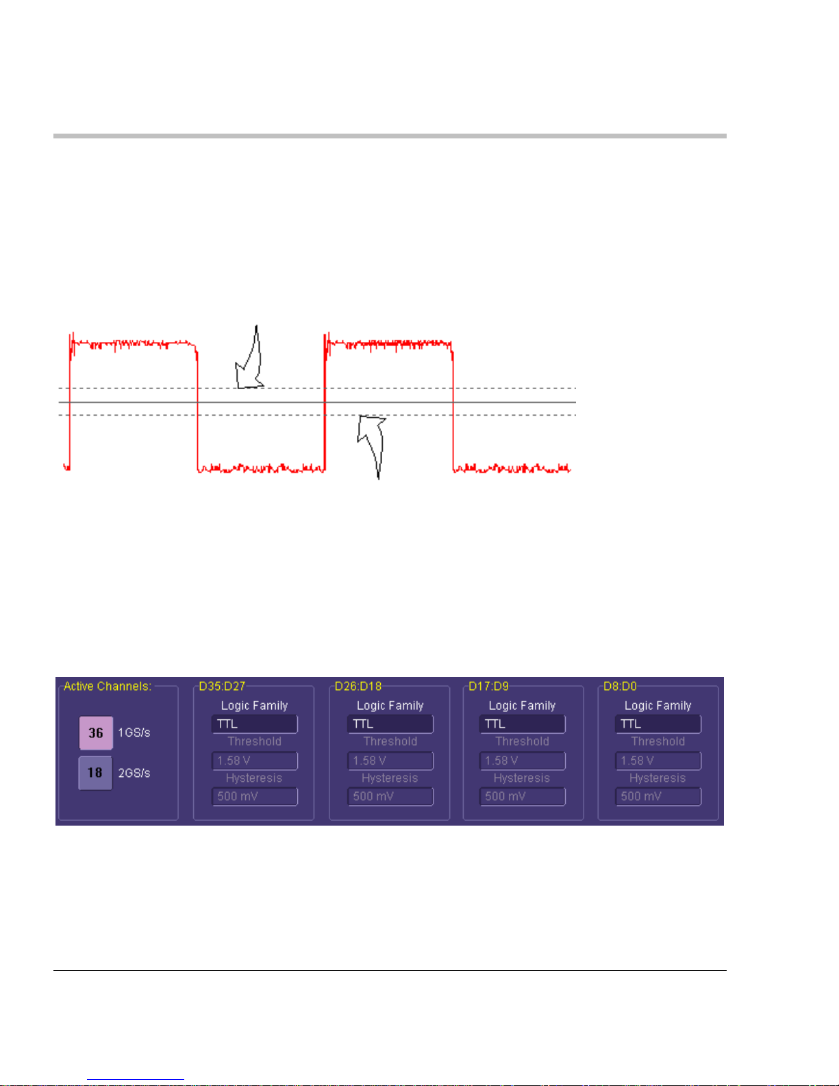
Input voltages less than the threshold are converted to 0. Input voltages greater than the
threshold are converted to 1.
Digitized
waveform
Input
signal
Threshold level
Sample points
The threshold levels can be set between –10.0 V and +10.0 V. TTL circuits use a threshold
voltage level of 1.58 V. ECL circuits use a threshold voltage level of -1.39 V. Other threshold
settings are available in the setup dialog.
Page 19

MS-500-OM-E Rev C ISSUED: June, 2009 19
Minimum voltage swing
The minimum high voltage level is user definable by the hysteresis control up to 1.4 V above the
threshold. The maximum low voltage level is user definable by the hysteresis control up to 1.4 V
below the threshold. The minimum signal swing is 100 mV. The indeterminate range of 50 mV
around the threshold voltage level is the level below which the MS-500 will not operate. However,
the MS-500 can support a signal as low as 100 mV only if the input signal’s quality is adequate.
Basic Oscilloscope Operation
For information on using the oscilloscope to view analog signals, reference your oscilloscope online Help system.
Threshold from - 50 mV to - 1.4 V
Threshold from + 50 mV to + 1.4 V
Page 20

MS-500 Mixed Signal Oscilloscope Option
20 ISSUED: June, 2009 MS-500-OM-E Rev C
ACCESSING THE MS-500 OSCILLOSCOPE MIXED SIGNAL OPTION TOOLSET
Overview
MS-500 trigger and digital line display tools are easily accessible in a variety of ways. The MS500 option adds additional dialogs (menus) to the existing oscilloscope. These dialogs are
defined as:
Digital setup – allows set up of the Digital lines and definition/display of parallel buses.
These dialogs are roughly analogous to the analog Channel setup dialogs in terms of
how they are accessed and how they operate in the software. However, there are no
dedicated front panel controls for digital channels as there are with analog channels.
Logic Setup – allows setup of the logic threshold value that defines the digital trace.
When the MS-500 is connected to the oscilloscope, these dialogs are conveniently accessed
with just one or two touches of the screen, making adjustment fast and easy.
Oscilloscope Analog Trigger and MS-500 Digital Trigger
A standard WaveRunner or WaveSurfer oscilloscope only allows analog triggering. The addition
of the MS-500 option adds enhanced triggering; the digital channels are now available in the
oscilloscope trigger menu as trigger sources.
To operate the oscilloscope with a normal analog trigger, simply open the trigger dialog, and then
select one of the oscilloscope channels as the source. For more information on setting up an
Analog trigger, consult your oscilloscope On-Line Help or Getting Started Manual.
When the MS-500 is connected to the oscilloscope, the trigger type defaults to Pattern Trigger,
and the Pattern Trigger tab is automatically displayed on the oscilloscope display dialog. If
desired, touch the Close button to not display the dialog.
Page 21
MS-500-OM-E Rev C ISSUED: June, 2009 21
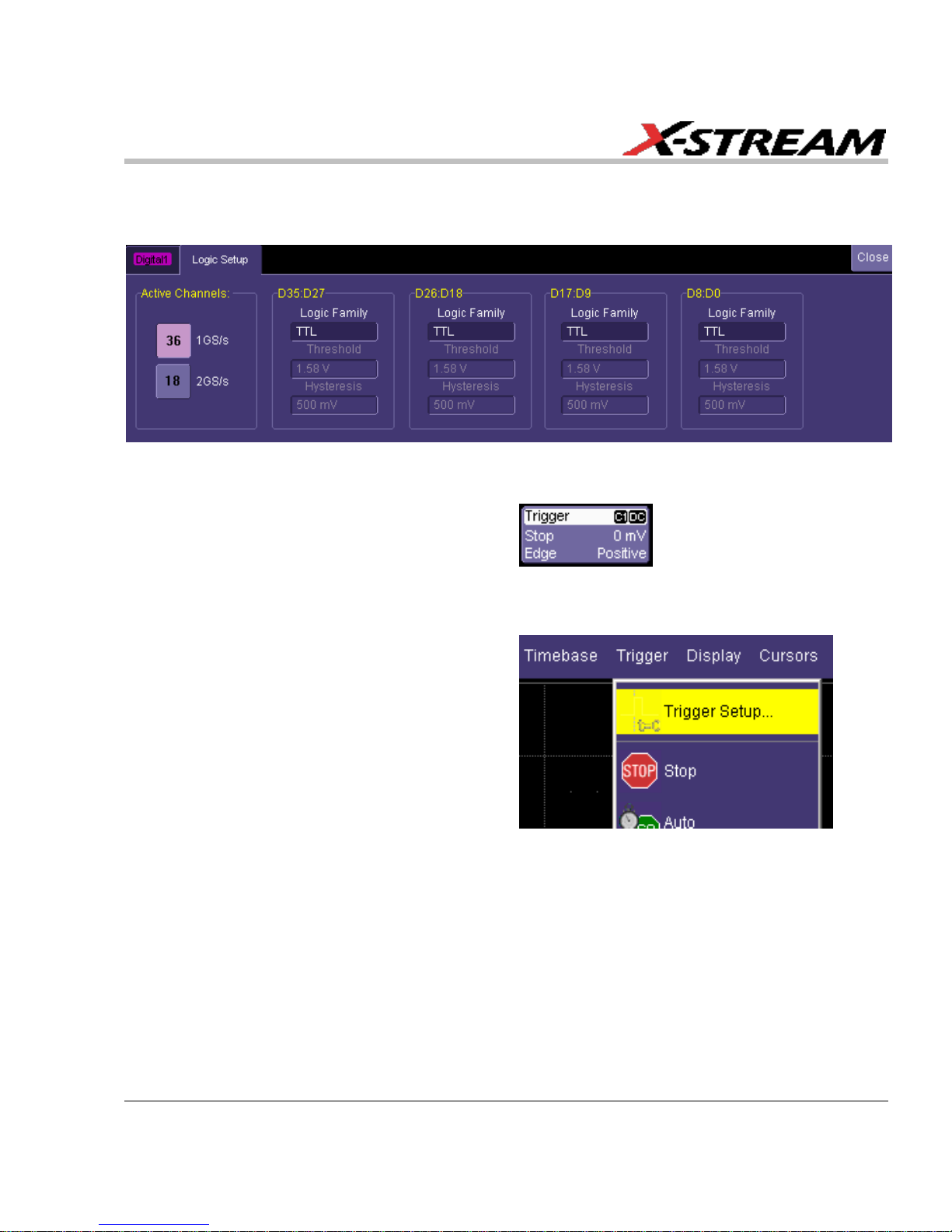
As a convenience to the operator, the Digital Logic Setup dialog is displayed in both the Trigger
dialogs and the Digital dialogs. Logic Setup is where you can set the crossing threshold for
determining whether the logic level is a 1 or a 0.
Other ways to access the MS-500 Trigger dialogs include:
1. Touching the Trigger trace descriptor
label. If the MS-500 is connected to the
oscilloscope, the dialog defaults to the
Digital Trigger tab. Follow the previous
instructions to select either an Analog
or Digital trigger.
2. Touching Trigger → Trigger Setup on
the menu bar. Then select either an
Analog or Digital trigger (as required).
Digital Trace Groups
These dialogs provide the ability to define up to 4 different groups of digital signals, and associate
from 1-36 digital lines with each group. Digital lines may be associated with more than one group.
As a group, the signals can be resized, repositioned, named, stored to memory, collapsed into a
bus trace/value, or moved to a different grid (WaveRunner Xi Series only).
Page 22

MS-500 Mixed Signal Oscilloscope Option
22 ISSUED: June, 2009 MS-500-OM-E Rev C
You can access these dialogs at any other time by using the following steps:
1. Touch Vertical on the menu bar, and select one of
the four Digital traces. This turns the Digital trace
ON and opens the corresponding dialog box.
2. If the Digital trace is already ON, the trace
descriptor label is highlighted and you can
configure the setup dialog for that Digital trace.
3. The Digital trace descriptor labels contain
information about the Digital Sample Rate (top
line), the maximum number of digital samples
(bottom line), and the number of channels in the
grouping (top right).
Page 23

MS-500-OM-E Rev C ISSUED: June, 2009 23
DIGITAL TRACE GROUP SETUP
Digital trace groups are very similar to analog channels – they can be turned ON or OFF, they can
be increased in size, and they can be positioned on the grid. You can also store them as
waveform files. In software, they are accessed through the same Vertical dialog as analog
channels. Cursors and most timing measurements also work with Digital traces.
Notable differences include the lack of sampling information in the trace data and the lack of
dedicated front panel controls (though some front panel controls double as position and size
controls when the Digital trace group is active).
However, Digital trace groups have capability far beyond that of an analog channel. Each Digital
trace group can consist of 1-36 digital lines. You can create up to four Digital trace groups, and
each digital line can be used in as many or as few groups as desired. You can choose to display
the group of digital lines as individual digital traces (one per line), or as a “collapsed” bus with bus
data values calculated on screen within the bus trace. Since there are so many digital lines,
Digital lines or buses can be renamed so that it is easier to keep track of the multitude of digital
signals on the screen.
Digital Trace Group Dialog
The following image shows the Digital trace group dialog with an overview of its operation:
Turn the
Digital
trace
group ON
or OFF,
just like a
Channel
Use the
arrow
buttons to
scroll
through all
36 digital
lines
Click on these
boxes with a
mouse, or just
use them as a
summary view
Add a digital line
to the Digital
trace group by
checking this
box
Change Digital
Line name by
touching this
box
Page 24

MS-500 Mixed Signal Oscilloscope Option
24 ISSUED: June, 2009 MS-500-OM-E Rev C
Additional capability is described in the following table:
Provides a method to quickly turn all digital lines in
the Digital trace group OFF or ON. The default is
for all digital lines to be ON. As lines are turned
OFF, they automatically resize to take up more of
the grid and be easier to see.
There are no dedicated front panel controls for
Digital line position or size. However, you can
touch these controls twice and enter in a unit-less
value for position and size using the pop-up
keypad. Or you can touch them once, and use the
front panel adjust knob to change the value.
Another way is to activate the Digital trace group
by touching the trace descriptor label once and
then using the front panel channel controls (V/div
and Offset) to adjust the position and size.
You can view a group of digital traces as individual
lines (Expand mode), like this:
Or collapsed into a bus (Collapse mode), like this:
Just select the appropriate button to get the view
that you want.
Page 25

MS-500-OM-E Rev C ISSUED: June, 2009 25
You can rename the collapsed bus for easier
identification from the oscilloscope grid. For
instance, if we were to name Digital1 as ADDR, it
would appear as follows on the grid:
Where ADDR appeared on the far left side of the
grid. Very long bus names can be used, but the
longer the name; the more bus data is obscured.
You can store a Digital trace group to memory, or
move it to another grid, just like you would a
Channel. These controls function identically for
Channels and Digital trace groups.
Note: WaveSurfer does not have the Next Grid capability.
Digital Logic Threshold Setup
Overview
The threshold level determines how the input signal is interpreted. The threshold level can be set
in either the Digital Setup or Digital Trigger Setup menus (it is the same setup, but is in two
different places for operator convenience). Input voltages less than the threshold are converted to
0. Input voltages greater than the threshold are converted to 1.
Digitized
waveform
Input
signal
Threshold level
Sample points
Page 26
MS-500 Mixed Signal Oscilloscope Option
26 ISSUED: June, 2009 MS-500-OM-E Rev C
The threshold levels can be set between -10.0 V and +10.0 V. TTL circuits use a threshold
voltage level of 1.58 V. ECL circuits use a threshold voltage level of -1.39 V. Other threshold
settings are available in the setup dialog.
The minimum high voltage level is user definable by the hysteresis control up to 1.4 V above the
threshold. The maximum low voltage level is user definable by the hysteresis control up to 1.4 V
below the threshold. The minimum signal swing is 100 mV. The indeterminate range of 50 mV
around the threshold voltage level is the level below which the MS-500 will not operate. However,
the MS-500 can support a signal as low as 100 mV only if the input signal’s quality is adequate.
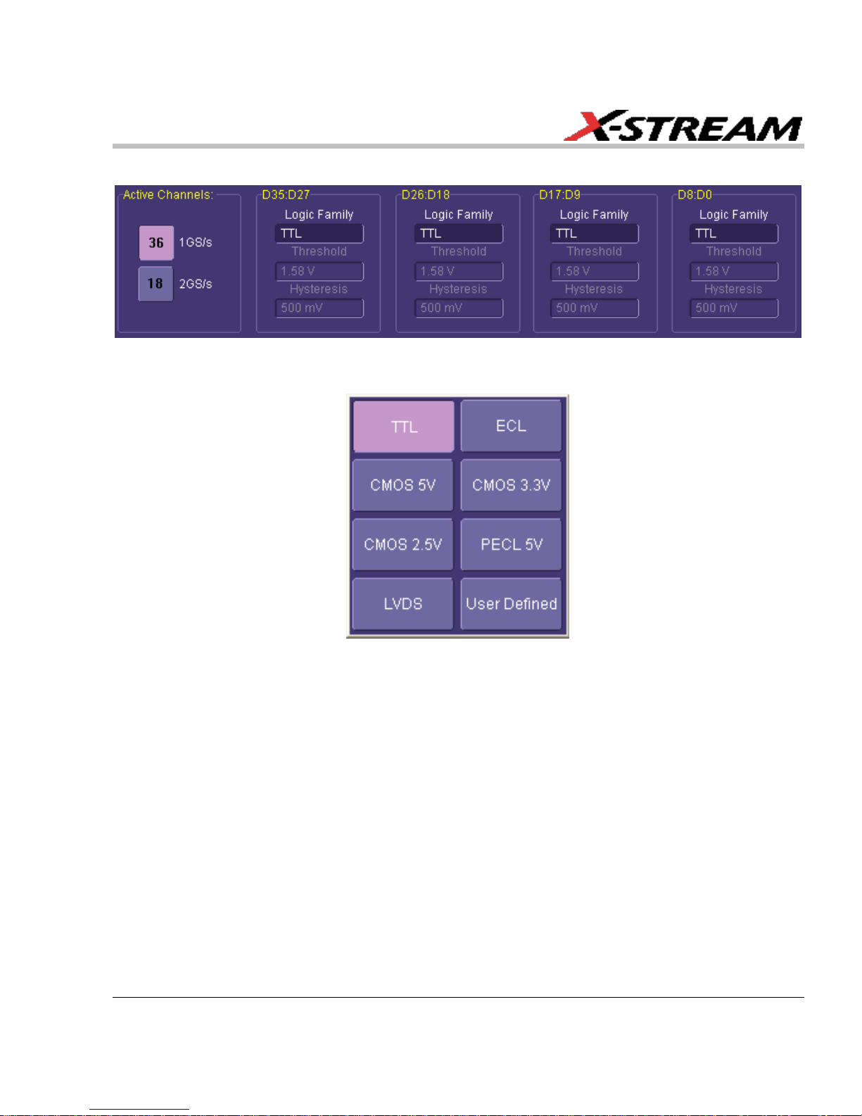
Digital Logic Setup
The Digital Logic Threshold Setup dialogs are contained in both the Trigger dialogs and in the
Digital Setup dialogs. It is important to note that a selection made in one location does affect the
value in the other. Up to four different logic levels can be selected: levels can be set for lines D0
to D8, D9 to D17, D18 to D26 and D27 to D35. When connecting your lines, make sure that all
lines with like levels are connected to the same set of 9 digital lines.
Touch the Logic Setup tab to view the following dialog:
You can select various Logic Families, or select User Defined and define a custom threshold
crossing.
Threshold from - 50 mV to - 1.4 V
Threshold from + 50 mV to + 1.4 V
Page 27

MS-500-OM-E Rev C ISSUED: June, 2009 27
Touch inside the Logic Family selection to view a selection list.
If you select User Defined, then you are able to define the voltage level. Otherwise, the Voltage
Level selection is grayed out.
Page 28

MS-500 Mixed Signal Oscilloscope Option
28 ISSUED: June, 2009 MS-500-OM-E Rev C
DIGITAL TRIGGER SETUP
Overview
While the MS-500 Mixed Signal Oscilloscope option has a very powerful and flexible Digital
trigger, it is also very easy to set up basic triggering. Connecting the MS-500 to your circuit is
described in the preceding chapters and is a digital triggering requirement.
When the MS-500 option is loaded onto the oscilloscope, additional trigger capabilities are added
to the normal oscilloscope trigger. These new trigger capabilities permit you to select digital lines
as the sources for your oscilloscope triggers such as Edge, Width, Glitch, Interval and Dropout.
Other triggers can work as combination triggers incorporating analog and digital triggering
capabilities. These triggers are Qualified (A-B Event Trigger) and Logic Pattern Trigger.
Creating a Pattern Trigger
There are two different ways to trigger digitally as follows:
Logic – permits creation of a simple or complex
analog/digital cross-pattern trigger condition with
a mix of 0, 1, rising edge, falling edge, either
edge, or don’t care conditions on up to 4 analog
channels and 18 digital lines.
Logic Bus – permits creation of a digital trigger
that corresponds to a hexadecimal bus value for
up to 18 digital bits.
Filter Out Unstable Conditions – Use this filter to ignore short glitches in logic state triggers that
last less than 3.5ns. If the box is unchecked all logic states are shown. This filter is enabled by
default
Page 29
MS-500-OM-E Rev C ISSUED: June, 2009 29
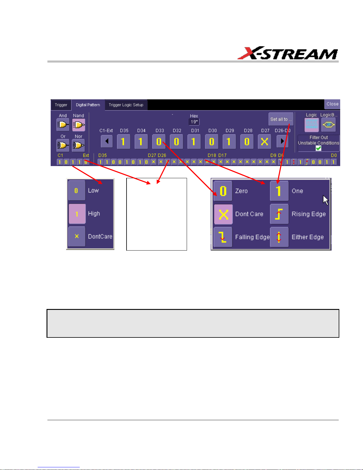
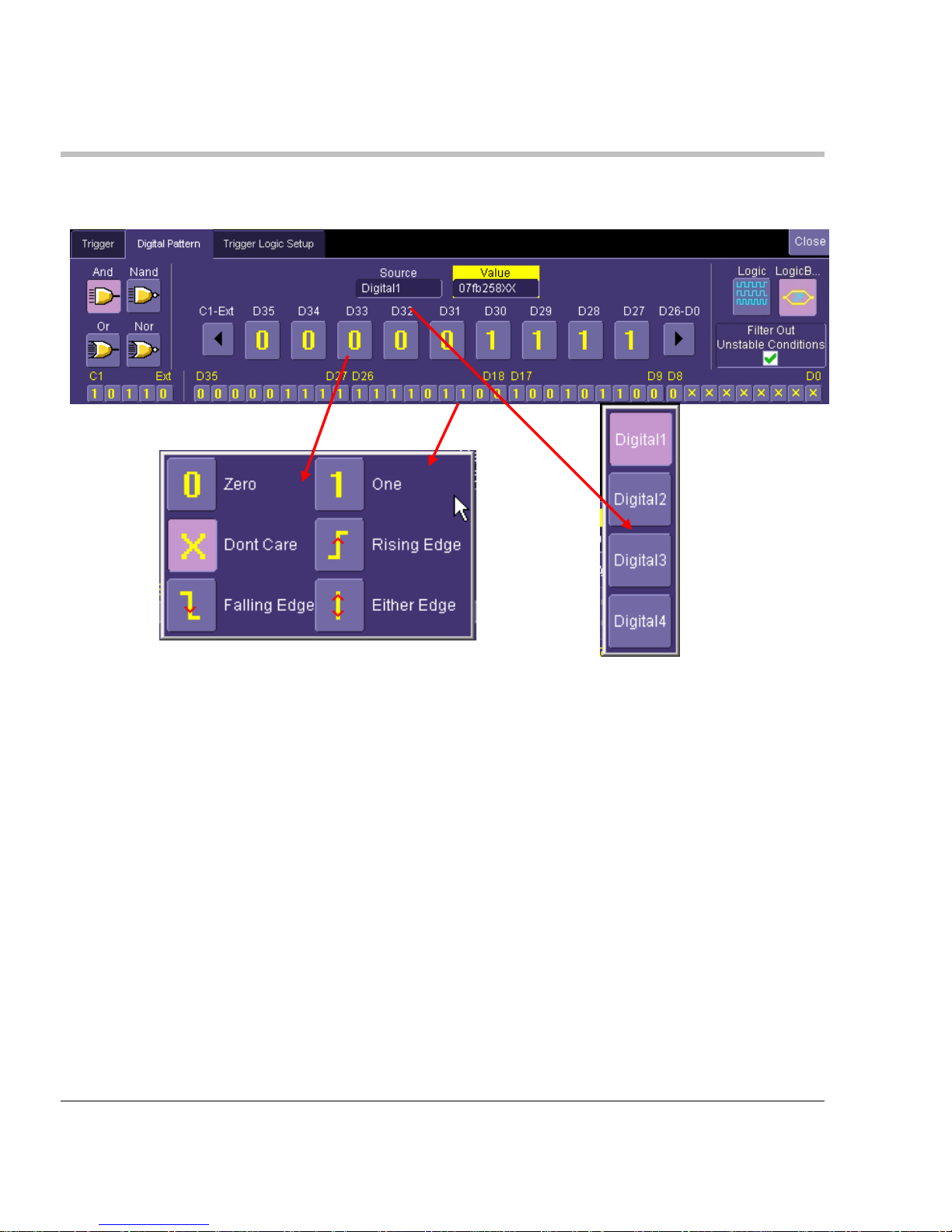
Logic Pattern Trigger Setup
The Logic Pattern Trigger dialog, with detail on some of the setup conditions, is shown in the
following images:
Select a value for any of the digital lines by touching the existing value (using either your finger or
a mouse), opening the pop-up menu with a list of choices, and then selecting one of the choices.
Alternatively, you can set a hex value by byte (or view what the resulting hex value conversion).
Touch the arrow buttons to scroll to the next group of eight digital lines. Note that you may set a
digital line to any value in the Logic trigger setup even if it is not defined as part of a Digital group.
PLEASE NOTE THE FOLLOWING:
You may set a digital line to any value in the Logic trigger setup even if it is not defined as part of a Digital group.
You can set multiple digital lines to different edge conditions. However, the edge conditions are always grouped in an
OR trigger condition.
Logic Pattern
Trigger can be
configured to
use up to 4
analog channels
and 36 digital
channels
Page 30
MS-500 Mixed Signal Oscilloscope Option
30 ISSUED: June, 2009 MS-500-OM-E Rev C
Logic Bus Trigger Setup
The Logic Bus Trigger setup dialog is shown as follows:
The Logic Bus trigger dialog is very similar to the Digital Logic trigger dialog. The main difference
is that you must select a Digital source (Digital1, Digital2, Digital3, or Digital4). In addition, only
those bits that are defined as part of that Digital group can be defined in the Logic Bus setup
dialog. A hexadecimal data value can be entered directly, or read as a result of the binary setup.
Digital Logic Threshold Setup
The Digital Logic Threshold Setup dialogs are located on both the Trigger and Digital Setup
dialogs. It is important to note that a selection made in one location does affect the value in the
other. Four different logic levels can be selected. One level can be set for each of the four groups
D0 to D8, D9 to D17, D18 to D26, and D27 to D35. When connecting your lines, make sure all
lines with like levels are connected to the same set of 9 digital lines.
Page 31
MS-500-OM-E Rev C ISSUED: June, 2009 31
Touch the Logic Setup tab to view the following dialog:
You can select various Logic Families, or select User Defined and define a custom threshold
crossing. Touch inside the Logic Family selection to view a selection list.
If you select User Defined, voltage level can be defined. Otherwise, the Voltage Level selection is
grayed out.
Page 32

MS-500 Mixed Signal Oscilloscope Option
32 ISSUED: June, 2009 MS-500-OM-E Rev C
CHARACTERIZE DIGITAL OR MIXED SIGNAL SYSTEM PERFORMANCE
Overview
The oscilloscope contains a number of built-in tools, such as cursors, measurement parameters,
statistics, and optional graphical analysis tools that allow you to characterize your DUT’s
performance. The number and type of these tools change depending on whether you are using a
WaveRunner or a WaveSurfer oscilloscope and what other software options are loaded on your
instrument. The tools can be used on the Digital traces and buses just like they are used on any
channel.
You may want to use cursors for making single-shot timing measurements, and measurement
parameters when you need to accumulate statistical data over many different acquisitions.
Using Cursors
Use horizontal cursors to mark locations on the waveform where the time measurement should
be done, then read the cursor values to establish the measurement. As necessary, adjust the
timebase or create zooms of the channel(s) and the Digital trace groups to view the signal with
enough detail. This is a good method for single-shot / single measurements.
Note that when Horizontal (Time) cursors are ON, the hexadecimal bus values for each Digital
trace group appear on the Digital trace descriptor label.
This can be useful when trying to measure to a specific bus value.
Page 33

MS-500-OM-E Rev C ISSUED: June, 2009 33
Using Measurement Parameters
Measurement parameters can be used to make basic timing and other measurements of your
digital or mixed-signal system. Basic parameters, such as Delay, Delta Delay, Frequency, Period,
Width, and Duty Cycle (not all parameters are available in WaveSurfer) can be used with a digital
line as a source.
Delay – Time from the trigger to the first transition at the 50% crossing
Delta Delay – Time between the 50% crossing of first transition of two
waveforms
Duty Cycle – Percent of time data is above 50%
Frequency – Frequency of every cycle in a waveform at the 50% level
and positive slope
Period – Period of every cycle in a waveform at the 50% level and
positive slope
Width – Width measured at the 50% level (can be positive or negative
slope)
Measurement Gating
Gating is available on each parameter so you can set a measurement window in which the
parameter should be activated. This allows you to eliminate unwanted portions of the acquisition
from your measurement.
Select gating from the Measure dialog by
selecting the tab for the appropriate
measurement (P1, P2, etc.) and then setting
the start and stop for the gate. Reference the
oscilloscope’s On-Line Help for more
information on how to set gating.
Page 34

MS-500 Mixed Signal Oscilloscope Option
34 ISSUED: June, 2009 MS-500-OM-E Rev C
Using Statistics and Graphing
Statistics and Histicons (WaveRunner Xi only) allow you to gather
numerical and visual information on the distribution of your various
measurements.
You can turn on Statistics and Histicons separately in the Measure
dialog. Simply touch the appropriate box to checkmark it and turn it
ON; or touch it again to turn it OFF.
In addition, some optional LeCroy programs (WaveRunner Xi only)
add capability to produce larger histograms and trends of your
measurement parameters. If you have this capability, then you can
access it through the Measurement Parameter setup dialog (the Px
tab).
Page 35

MS-500-OM-E Rev C ISSUED: June, 2009 35
ISOLATE AND ANALYZE SIGNAL ACTIVITY
The combination of Analog Triggering, Digital Triggering, Analog Capture, Digital Capture, and
normal oscilloscope features is a powerful combination of tools that can make it very easy to find
latent HW or SW problems in your circuit. The oscilloscope is no longer a tool only for hardware
engineers. Now software engineers can easily visualize the mix of analog and digital signals and
relate it to programming code and operation.
Some common mixed signal analysis needs and methods are discussed as follows:
Capture Long Pre-Trigger Time
LeCroy oscilloscopes are available with optional very long acquisition memory. For instance,
analog channels on the WaveRunner Xi oscilloscope can capture up to 12.5 Mpts on 4 channels,
or 25 Mpts on 2 channels. WaveSurfer Xs oscilloscopes can capture up to 10 Mpts on 4 channels
The MS-500 option adds 900 Mpts of digital memory (50 Mpts/ch on 18 channels, 25 Mpts/ch on
36 channels). If you wish, all this memory can be 100% pre-trigger, 100% post-trigger, or
something in between.
1. Adjust Pre-Trigger and Post-Trigger time
by adjusting the Delay knob on the
oscilloscope’s front panel.
2. Optimize your Sample Rate or Memory
Length by accessing the Horizontal
Dialog in your oscilloscope and selecting
as follows:
a. WaveRunner Series – either Set
Max Memory mode or Fixed
Sample Rate mode.
b. WaveSurfer Series – choose a
Max Number of Sample Points
3. Note that you must make sure that your
timebase setting and memory length
combined do not result in too low of a
sample rate, or your analog and digital
signals may not be acquired accurately.
Reference your oscilloscope’s On-Line Help or Getting Started Manual for more information on
these common settings.
Page 36

MS-500 Mixed Signal Oscilloscope Option
36 ISSUED: June, 2009 MS-500-OM-E Rev C
Zooming on Your Waveforms
There are a number of ways to zoom a mix of analog and digital signals. The easiest method is to
STOP the acquisition and then simply adjust the timebase Time/Div and Delay knobs on the front
panel.
Use the Time/Div knob to change the zoom ratio, and the Delay knob to change the position.
Note: When you adjust timebase to zoom, the position adjustment is limited by the maximum pre-trigger and post-trigger
delay adjustment available in your oscilloscope. Reference your oscilloscope manual for specifications of these delays.
You can also zoom by drawing a box with a mouse pointer around the area that you wish to
zoom. Follow these steps:
1. Select the area you wish to zoom by
drawing a box around it with a mouse
pointer.
Page 37

MS-500-OM-E Rev C ISSUED: June, 2009 37
2. A second grid is created of the zoomed
traces. Use either the Zoom control knobs
(WaveRunner Xi, WavePro 7 Zi,
WaveMaster 8 Zi, series) or the
Vertical/Horizontal control knobs
(WaveSurfer Xs Series) to adjust the
vertical and horizontal scale and position.
Reference your oscilloscope operator’s
manual for more information.
Reference your oscilloscope’s On-Line Help or Getting Started Manual for complete information
on zooming.
Page 38

MS-500 Mixed Signal Oscilloscope Option
38 ISSUED: June, 2009 MS-500-OM-E Rev C
APPENDIX A – SPECIFICATIONS
Digital Channels
Number
18 (36)
Memory
50 Mpts/Ch (25 Mpts/Ch) (10 Mpts/Ch when used with WaveSurfer Xs)
Probe Inputs
100 kΩ || 5.0 pF
Threshold Levels
TTL, ECL, CMOS (2.5, 3.3, 5 V), PECL, LVDS, or User Defined.
Sampling Rate
1 kS/s to 2 GS/s (1 GS/s maximum sampling rate on 36 channels).
Maximum Input
Voltage Range
± 30 V non-destruct (See voltage derating curve on next page)
Minimum Input
Voltage Range
±50 mV around the threshold voltage setting
Digital Channel
Grouping
4 digital groups can be defined. Each group may use any combination of
18 digital lines. Groups can be displayed as individual lines, or collapsed
into a bus view.
Triggering
User selectable analog (i.e., std. oscilloscope trigger) or digital trigger
Digital Trigger
Setup Type
Logic Pattern or Logic Bus
Logic Setup
Up to 36 digital lines, with any combination of 0, 1, or X (don’t care). In
addition, a Rising Edge, Falling Edge, or Either Edge condition may also
be set (Note: multiple edges are OR combined).
Logic Bus Setup
Up to 18 digital lines, defined in hexadecimal format
Accuracy
+/-1 ns (typical)
Setup Type
Logic Pattern or Logic Bus
Physical
Dimensions
4.25” x 8.375” x 1.5” (10.8 x 21.2 x 3.8 cm) (W x L x D)
Pod Weight
1.7 lbs ( .775 kg)
Complete Kit
18” x 13.25” x 4.25” (45.75 x 33.65 x 10.795 cm) (W x L x D)
Page 39

MS-500-OM-E Rev C ISSUED: June, 2009 39
CERTIFICATIONS
CE Compliant
CE Declaration of Conformity
The accessory meets requirements of EMC Directive 2004/108/EC for Electromagnetic
Compatibility and Low Voltage Directive 2006/95/EC for Product Safety.
EMC Directive
EN 61326-1:2006
EMC requirements for electrical equipment for measurement, control, and laboratory use.
Electromagnetic Emissions:
EN 55011/A2:2002, Radiated and conducted emissions (Class A)*
Electromagnetic Immunity:
EN 61000-4-2:2001 Electrostatic Discharge.
(4 kV contact, 8 kV air, 4 kV vertical/horizontal coupling planes)
EN 61000-4-3:2006 RF Radiated Electromagnetic Field.
(3 V/m, 80-1000 MHz; 3 V/m, 1400 MHz - 2 GHz; 1 V/m, 2 GHz - 2.7 GHz)
* This is a Class A product. In a domestic environment this product may cause radio interference,
in which case the user may be required to take appropriate measures.
Low-Voltage Directive
EN 61010-031:2002
Safety requirements for electrical equipment for measurement, control, and laboratory use.
Page 40

MS-500 Mixed Signal Oscilloscope Option
40 ISSUED: June, 2009 MS-500-OM-E Rev C
Max. VIN versus Frequency
Note: Max VIN < 30V (DC + Peak AC)
0
5
10
15
20
25
30
35
1 M 10 M 100 M 1000 M
Frequency (Hz)
V
IN
(Vrms)
§ § §
 Loading...