

Page 1
LeCroy WaveStation
LW4001LW400A Series AWG
Remote Programmer’s Manual
August 1996
Rev. C
Page 2

LeCroy
Corporate Headquarters
700 Chestnut Ridge Road
Chestnut Ridge, NY 10977-6499
Tel: (914) 578-6020, FAX: 578-5985
European Headquarters
Mannheimerstrasse 175
D-69123 Heidelberg, Germany
Tel: (49) 6221 840989
FAX: (49) 6221 833827
European Manufacturing
2, rue du Pr6-de-la-Fontaine
P.O. Box 341
1217 Meyrin 1/Geneva, Switzerland
Tel: (41) 22 719 21 11, FAX: 22 782 39
Copyright August 1996, LeCroy. All dghts reserved. Information in this publication supersedes all earlier versions.
Specifications subject to change.
LeCroy® Is a registered trademark of LeCroy Corporation
WaveStation® is a registered trademark of LeCroy Corporation
Centronics® is a registered trademark of Data Computer Corp.
Citizen® is a registered trademark of Citizen America Corp.
Epson® is a registered trademark of Epson Amedca Inc.
Hewlett-Packard® is a registered trademark, and HP
IBM® is a registered trademark, and IBM PC/XT
Business Machines Corporation.
MATHCAD® is a registered trademark of MATHSOFT INC.
MATLAB® is a registered trademark of MATHWORKS
PSPICE® is a registered trademark of MICROSIM Corporation
Smart Trigger
Microsoft®, MS-DOS®, QuickBasic®, Excel® and Windows® are trademarks of Microsoft Corporation.
PCX is a file format developed by ZSoft Corporation for use with PC Paint programs.
Bubble Jet® is a registered trademark of Canon USA, Incorporated.
Apple® and Macintosh® are registered trademarks of Apple Computer, Incorporated.
TM
is a trademark of LeCroy Corporation
TM
is a trademark of Hewlett-Packard, Co.
r",
PC/AT
TM
and PSI2
TM
are trademarks of International
Page 3

TABLE OF CONTENTS I
SECTION 1
GENERAL INFORMATION
Initial Inspection .............................................................................. 1-1
Warranty .........................................................................................
Product Assistance ..........................................................................
Maintenance Agreements ................................................................ 1-2
Service Procedure ........................................................................... 1-2
Return Procedure ............................................................................ 1-2
How to Use This Manual ................................................................. 1-3
Introduction .....................................................................................
What is SCPI ...................................................................................
SECTION 2
ABOUT REMOTE CONTROL
Interface Configuration and Special Commands ............................. 2-1
GPIB Remote Control ...................................................................... 2-1
GPIB Signals and Lines .................................................................. 2-1
Setting the GPIB Address ............................................................... 2-1
GPIB Remote Control and Hardcopy Operation ..............................
Remote Control Operation over GPIB ............................................. 2-2
End or Identity (EOI) Operation ....................................................... 2-2
Hardcopy Operation over GPIB .......................................................
IEEE-488 Standard Messages ........................................................ 2-3
Checking GPIB Communications Using National
Instruments IBIC Program ............................................................. 2-5
Error Code .......................................................................................2-7
1-1
1-1
1-5
1-5
2-2
2-2
SECTION 3
INSTRUMENT MODEL AND SUBSYSTEM HIERARCHY
Remote Command System Model ................................................... 3-1
Introduction to SCPI Command Syntax ........................................... 3-1
Command Subsystems ................................................................... 3-4
Overview of OUTPut Commands .................................................... 3-5
Overview of WAVE Commands ....................................................... 3-5
Overview of FGEN Commands .....................................................
Overview of EQUation Commands ................................................
Overview of DISPlay Commands .................................................. 3-15
Overview of HCOPy Commands ................................................... 3-17
3-11
3-14
Page 4

TABLE OF CONTENTS
Overview of TRIGger Commands .................................................
Overview of MMEMory Commands ...............................................
Overview of PROJect Commands .................................................
Overview of SYSTem Commands .................................................
Overview of STATus Commands .................................................
488.2 Command Commands .........................................................
SECTION 4
STATUS & ERROR REPORTING
Status Register ................................................................................
Status Byte Operation .... . ................................................................
Status Data Structures ....................................................................
Querying the Operational and Questionable Status Register ..........
Event Enable Registers ...................................................................
Status Byte Register Definition ........................................................
Checking Status and Requesting Service .....................................
GPIB Service Request ..................................................................
SECTION 5
WAVEFORM TRANSFERS VIA GPIB
Introduction .....................................................................................
Transferring Waveforms via GPIB .................. . ................................5-1
The Data Interchange Format (DIF) ................................................
Viewing Waveform Data in the DIF File ...........................................
Other Data Formats ........................................................................
3-18
3-19
3-20
3-21
.3-22
3-23
4-1
4-1
4-1
4-3
4-4
4-6
4-12
4-15
5-1
5-2
5-5
5-8
SECTION 6
REMOTE COMMANDS .......................................................................
SECTION 7
REMOTE PROGRAMMING EXAMPLES
Introduction .....................................................................................
Setting Up the Environment for
QuickBASIC Programming ............................................................
The LWGPIB.BAS Program ............................................................
End Or Identify (EOI) Operation ......................................................
Initializing GPIB Communication with the AWG ...............................
Sending a Command to the LW400 Series AWG ............................
6-1
7-1
7-1
7-2
7-9
7-9
7-9
Page 5
I TABLE OFCONTENTS I
Sending a Query, Reading the Response, and
Using Status to Determine When the Operation is Done ...............
Downloading a Waveform .............................................................
Uploading a Waveform DIF File to the AWG ................................. 7-12
INDEX
INDEX OF REMOTE COMMANDS
7-10
7-11
Page 6

I TABLEOF CONTENTS
THIS PAGE LEFT INTENTIONALLY BLANK
Page 7
INITIAL INSPECTION
It is recommended that the shipment be thoroughly inspected
immediately upon delivery to the purchaser. All material in the
container should be checked against the enclosed Packing List.
LeCroy cannot accept responsibility for shortages in comparison
with the Packing List unless notified promptly. If the shipment is
damaged in any way, please contact the Customer Service
Department.
WARRANTY
LeCroy warrants its products to operate within specifications
under normal use for a period of one year from the date of
shipment. Spares, replacement parts and repairs are warranted
for 90 days. The instrument’s firmware is thoroughly tested and
thought to be functional, but is supplied "as is" with no warranty
of any kind covering detailed performance. Products not
manufactured by LeCroy are covered solely by the warranty of
the original equipment manufacturer.
In exercising this warranty, LeCroy will repair or, at its option, replace any product returned to the Customer Service Department
or an authorized service facility within the warranty period,
provided that the warrantor’s examination discloses that the
product is defective due to workmanship or materials and that
the defect has not been caused by misuse, neglect, accident or
abnormal conditions or operation.
The purchaser is responsible for transportation and insurance
charges for the retum of products to the servicing facility. LeCroy
will return all in-warranty products with transportation prepaid.
This warranty is in lieu of all other warranties, expressed or im-
plied, including but not limited to any implied warranty of mer-
chantability, fitness, or adequacy for any particular purpose or
use. LeCroy shall not be liable for any special, incidental, or con-
sequential damages, whether in contract or otherwise.
PRODUCT ASSISTANCE
Answers to questions concerning installation, calibration, and
use of LeCroy equipment are available from the Customer
Service Dept., 700 Chestnut Ridge Road, Chestnut Ridge, New
York 10977-6499, U.S.A., tel. (914)578-6020.
1-1
Page 8
GENERAL INFORMATION
MAINTENANCE
AGREEMENTS
LeCroy offers a selection of customer support services. Maintenance agreements provide extended warranty and allow the
customer to budget maintenance costs after the initial one year
warranty has expired. Other services such as installation,
training, enhancements and on-site repair are available through
specific Supplemental Support Agreements.
UPDATED MANUALS
SERVICE PROCEDURE
LeCroy is committed to providing state-of-the-art instrumentation
and is continually refining and improving the performance of its
products. While physical modifications can be implemented
quite rapidly, the corrected documentation frequently requires
more time to produce. Consequently, this manual may not agree
in every detail with the accompanying product. There may be
small discrepancies in the values of components for the
purposes of pulse shape, timing, offset, etc., and occasionally,
minor logic changes. Where any such inconsistencies exist,
please be assured that the unit is correct and incorporates the
most up-to-date circuitry. In a similar way the firmware may
undergo revision when the instrument is serviced. Should this be
the case, manual updates will be made available as necessary.
Products requiring maintenance should be retumed to the
Customer Service Department or authorized service facility.
LeCroy will repair or replace any product under warranty at no
charge. The customer is responsible for transportation charges
to the factory. All in-warranty products will be returned to the
customer with transportation prepaid.
For all LeCroy products in need of repair after the warranty
period, the customer must provide a Purchase Order Number
before repairs can be initiated. The customer will be billed for
parts and labor for the repair, as well as for shipping.
1-2
Page 9
Introduction
GENERAL INFORMATION
RETURN PROCEDURE
HOW TO USE THIS MANUAL
To determine your nearest authorized service facility, contact the
Customer Service Department or your field office. All products
retumed for repair should be identified by the model and serial
numbers and include a description of the defect or failure, name
and phone number of the user, and, in the case of products
returned to the factory, a Retum Authorization Number (RAN).
The RAN may be obtained by contacting the Customer Service
Department in New York, tel. (914)578-6020. Return shipments
should be made prepaid. LeCroy will not accept C.O.D. or
Collect Return Shipments. Wherever possible, the original
shipping carton should be used. If a substitute carton is used, it
should be rigid and be packed such that the product is
surrounded with a minimum of four inches of excelsior or similar
shock-absorbing material. In addressing the shipment, it is
important that the Return Authorization Number be displayed on
the outside of the container to ensure its prompt routing to the
proper department within LeCroy.
This manual explains the programming protocol for controlling
the LW400/LW400A Series Arbitrary Waveform Generators,
including the LW420,LW420A, LW410 and LW410A, from a
host computer. These models may also be reffered to as the
WaveStation.
Pupose of this manual:
Gain an overview of the instrument remote programming
interface.
Familiarize yourself with the SCPI programming language as
it applies to the LW400/LW40OA.
Provide detailed information on all of the WaveStation
remote commands.
1-3
Page 10
GENERAL INFORMATION
The following sections are contained in this manual:
Section I
Section 2
Section 3
Section 4
Section 5
Section 6
Introduction
Gives a brief history of remote control interfaces and protocols
and explains the advantages of the SCPI command language
and how it is used in the WaveStation.
About Remote Control
Explains how to operate the WaveStation remotely across the
GPIB bus.
Instrument Model and Subsystem Hierarchy
Presents the function representation of the instrument as viewed
from the remote control interface, often referred to as the
instrument Model. Describes the command hierarchy and
introduces basic SCPI syntax and subsystems. Provides an
overview of the command hierarchy and how it relates to the
arbitrary waveform generator functional sections.
Statue and Error Reporting
Describes in detail the Status and Error reporting system.
Waveform Transfers via GPIB
Explains the format for transferring waveforms between an
extemal device and the WAVESTATION via GPIB.
Remote Commands
Provides a detailed command reference, including command
syntax and purpose.
Section 7
1-4
Remote Programming Example
Page 11

Introduction
Introduction
GENERAL INFORMATION
The remote control interface consists of hardware, the GPIB
port, as well as a software protocol. The hardware interfaces are
described in your user manual for the instrument. The software
protocol is described in this manual and builds upon the rapidly
emerging industry standard SCPI (Standard Commands For
Programmable Instruments).
What is SCPI
SCPI is a remote command language for test and
measurement instruments. It was developed by a consortium of
test and measurement instrument manufacturers and is
intended to provide a consistent programming language for
instrument control and data transfer.
IEEE-488 (GPIB) was adopted as a standard remote control
interface in 1975. The standard specified system
interconnections and communication protocols which provided a
universal hardware interface for integrating multiple instruments
into a test system. The original standard put instruments on a
common bus, but each instrument manufacturer used a
proprietary command set. Every time a user added a new
instrument to the bus, he had to leam another set of, often
enigmatic, commands. Updates to the standard in 1987, led to
IEEE-488.1 and 488.2 which further refined the standard but still
fell short of ensuring a common command syntax beyond a few
mandated "common commands". In 1990, the Standard
Commands for Programmable Instruments (SCPI) consortium
developed a system of common remote commands.
Although SCPI was originally defined for GPIB, it has now
spread well beyond that interface and is being used to support a
wide range of hardware interfaces. For example SCPI has
became a major element in the implementation of VXl based
systems.
The SCPI command language standardizes command syntax
and structure used in remote control of test and measurement
instrumentation and is being rapidly adopted by leaders in test &
measurement instrumentation. This allows the user to learn a
single set of remote commands for instruments which are
supplied by different manufacturers. Because the functionality of
instruments can vary widely, and because new instruments and
measurement techniques are constantly being developed, the
SCPI standard makes provision for new commands to be added
1-5
Page 12

GENERAL INFORMATION
as needed. Because LW400 has many unique features (for
example, waveform formats), LeCroy has enhanced the SCPI
language to provide access to these advanced capabilities.
SCPI benefits the user by providing a single command set for
integrating multiple instruments into a test system. The greatest
benefit occurs on the second or subsequent system integration
programs, where the user does not leam yet another command
language.
This manual will provide you with all the information you require
to control your LW400 using the SCPI programming language.
Because SCPI is an industry standard and not specific to
LeCroy, details on the generic standard are available in industry
standard SCPI manuals.
1-6
Page 13
2
ABOUTREMOTECONTROL I
I
Interface Configuration
and Special Commands
GPIB Remote Control
Controller
The WaveStation can be operated remotely from an instrument
controller or computer across the GPIB bus and commands
sent over GPIB can set or read any WaveStation front panel
instruction.
The GPIB bus can interconnect many instruments to allow
communication with one another over shared cables. The GPIB bus
uses a bit-parallel, byte-serial format. A device connected to the
GPIB is either a talker, listener, or controller. Although some
devices can change roles, a device can perform just one role at a
time.
Talker
Listener
Governs the operation of the bus. A controller, usually a computer,
normally sends program messages to devices and receives
responses from them. One controller task is to decide which device
is the talker and which is a listener(s). The controller may assign
itself to be the talker at one time, and a listener at other times. If
devices on the bus never change their roles, a controller is not
required.
Places messages or data on the GPIB bus for
transmission to other devices. Only one device on
the network can be the talker.
Receives data or commands over the bus. Several
listeners may be active at one time.
GPIB Signals and Lines
Setting the GPIB Address
The GPIB bus has 16 signal lines and eight ground lines. Eight of
the 16 signal lines form a bi-directional data bus which transfers data
and commands. The remaining eight signal lines control the bus
operation. Three lines are for handshaking signals which
synchronize data transmission. The remaining five lines are
management lines which control the flow of information across the
bus and take special action.
The GPIB address is set in the System Sub-menu, accessed
through the Project and Preference menu. From the front panel
press the Project key. Press the soft keys adjacent to the
Preferences and then system entries on the menus to enter the
system menu. Press the soft key adjacent to the GPIB entry on the
2-1
Page 14
ABOUT REMOTE CONTROL
menu to enter the GPIB setup menu. Turn the rotary to select the
GPIB address.
The factory default setting for the GPIB address is 1.
GPIB Remote Control and
Hardcopy Operation
Remote Control Operation
over GPIB
The WaveStation can communicate across the GPIB bus as a talker
or as a listener with a remote host controller (computer). For this
talker/listener remote control operation, the WaveStation conforms to
the guidelines specified by IEEE 488. The hardcopy output can also
communicate across GPIB in one of two ways. First, if the hardcopy
port is the same as the remote control port, then a remote hardcopy
command sends the output to the remote host as a query response.
Second, if the hardcopy port is different from the remote control port
or the local hardcopy key is pressed (Hardcopy Execute), then the
WaveStation enters talk only mode and does not expect any
controller present on the bus.
Talk/Listen The WaveStation enters this mode whenever a command is
received via the GPIB bus. In this mode, the Wavestation can both
receive commands and setups from the remote host computer
(controller) and send data and measurement results.
End or Identify (EOI)
Operation Except where specifically noted, all commands to and from the
WaveStation are terminated by asserting the EOI signal line
simultaneously with the last byte transmitted. No other command
terminators are required.
Hardcopy Operation over GPIB
Talk Only
2-2
The WaveStation enters this mode whenever the hardcopy
destination is set to GPIB and the Hardcopy Execute soft key is
pressed. Talk only is a special GPIB mode where there is no
controller allowed on the bus; the WaveStation is the only talker and
all connected devices must be listeners (i.e., printers/plotters must be
in Listen Only mode).
Page 15
I ABOUTREMOTE CONTROL
I
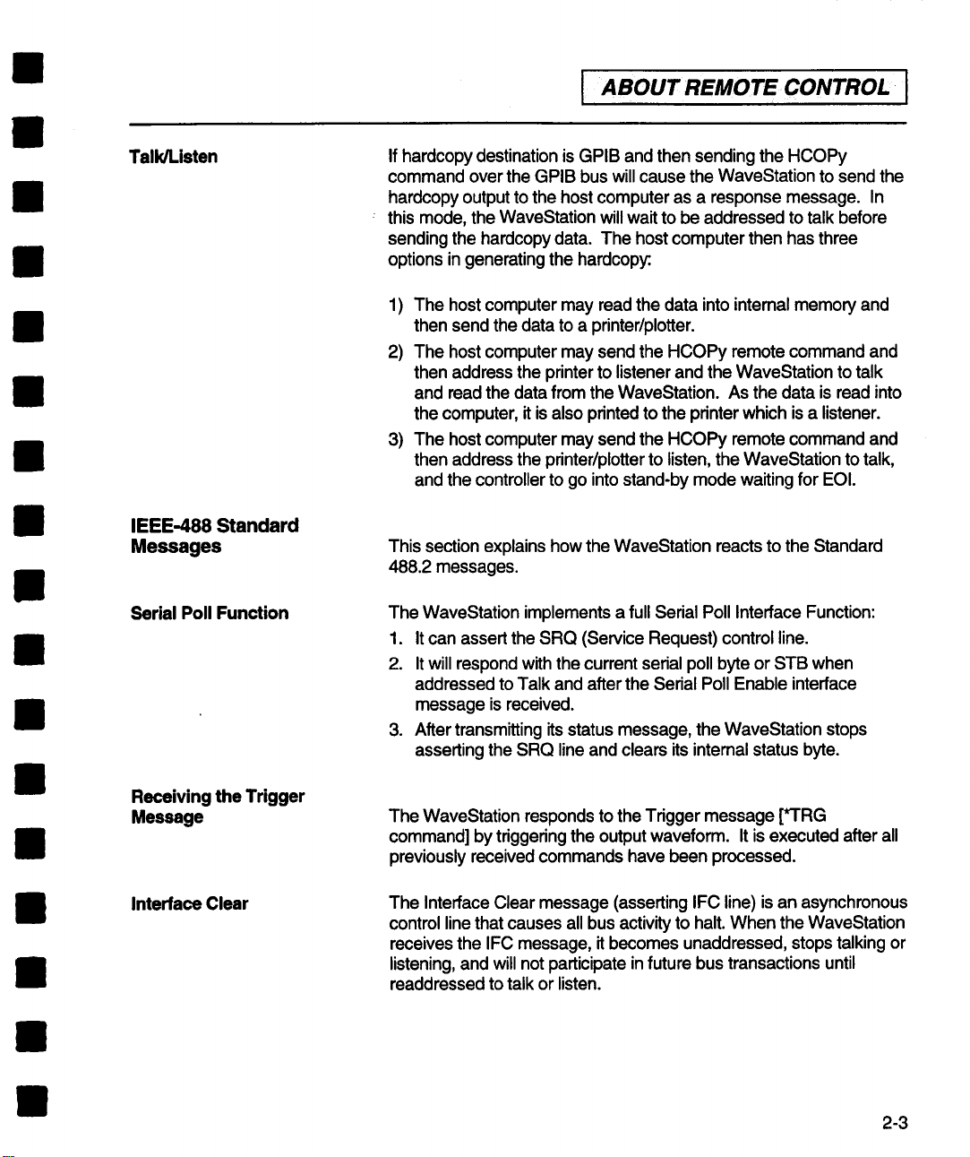
Talk/Listen
IEEE-488 Standard
Messages
Serial Poll Function
If hardcopy destination is GPIB and then sending the HCOPy
command over the GPIB bus will cause the WaveStation to send the
hardcopy output to the host computer as a response message. In
this mode, the WaveStation will wait to be addressed to talk before
sending the hardcopy data. The host computer then has three
options in generating the hardcopy:
The host computer may read the data into internal memory and
1)
then send the data to a printer/plotter.
The host computer may send the HCOPy remote command and
2)
then address the printer to listener and the WaveStation to talk
and read the data from the WaveStation. As the data is read into
the computer, it is also printed to the printer which is a listener.
The host computer may send the HCOPy remote command and
3)
then address the printer/plotter to listen, the WaveStation to talk,
and the controller to go into stand-by mode waiting for EOI.
This section explains how the WaveStation reacts to the Standard
488.2 messages.
The WaveStation implements a full Serial Poll Interface Function:
1. It can assert the SRQ (Service Request) control line.
It will respond with the current serial poll byte or STB when
2.
addressed to Talk and after the Serial Poll Enable interface
message is received.
After transmitting its status message, the WaveStation stops
3.
asserting the SRQ line and clears its intemal status byte.
Receiving the Trigger
Message
Interface Clear
The WaveStation responds to the Trigger message [*’I’RG
command] by triggering the output waveform. It is executed after all
previously received commands have been processed.
The Interface Clear message (asserting IFC line) is an asynchronous
control line that causes all bus activity to halt. When the WaveStation
receives the IFC message, it becomes unaddressed, stops talking or
listening, and will not participate in future bus transactions until
readdressed to talk or listen.
2-3
Page 16

4BOUT REMOTE CONTROL
~
Device Clear
(Selective or Universal)
Go to Local, Go to
Remote, Go to
Remote with Lockout
Local
The WaveStation will respond to a Selective Device Clear or a
the WaveStation first be addressed to listen, followed by the
the input buffer, the output queue, and the message available (MAV)
status bit to be cleared.
The WaveStation can operate in Local or Remote mode. In Local
the host computer will also be processed. In Remote mode, the
Universal Device Clear interface message. The former requires that
Selective Device Clear message. The latter does not require that the
instrument be previously addressed to listen. Device Clear causes
mode, all front panel controls are operational and commands from
WaveStation operates under computer control and no front panel
controls are operational except the Local soft key (if enabled). The
WaveStation always powers on in Local mode).
Note: The WaveStation processes all messages regardless of
being in Remote or Local modes.
The WaveStation switches to Remote mode (with Local soft key
enabled) when the WaveStation receives a command with the
REN line asserted. All instrument settings remain unchanged
during local-to-remote transitions. The WaveStation screen
indicates that Remote mode is enabled by the appearance of the
Local soft key. No other front panel controls operate.
2-4
If the WaveStation is under remote control and the Local soft key
is pressed, the instrument interrupts program control and returns
to local control. Data and/or settings cannot be changed locally.
Caution:. In Local Lockout state, all front panel keys and knobs
are disabled. Once Remote with Local Lockout is set using the
"RWLS" or "LLO" commands it can only be cleared when the
WaveStation is put into Local mode by sending the "LOC"
command or readdressing the WaveStation with REN
deasserted.
Page 17

I ABOUTREMOTECONTROLI
Checking GPIB
Communications Using
National Instruments IBIC
Program
This quick checkout requires a computer with a National Instrument
GPIB card and the National Instruments IBIC program supplied by
National Instruments with the purchase of a GPIB card. This quick
checkout also assumes that the GPIB card is already installed in the
computer and has passed all test successfully. For help installing or
configuring the National Instruments GPIB card please contact
National Instruments at (800) IEEE-488 or (512) 794-0100.
These example instructions are for an IBM-PC or compatible
computer. The method for other computers is very similar.
Change to the National Instruments GPIB-PC subdirectory with
the command:
CD \GPIB-PC
Start the IBIC program by with the command:
IBIC
Tell the IBIC program the address of the WaveStation (we
assume address 1) with the command:
IBFIND DEV1
Send the identify command to the WaveStation with the
command:
IBWRT "*IDN?"
Read the id of the WaveStation with the command:
IBRD 100
2-5
Page 18
ABOUT REMOTE CONTROL I
I
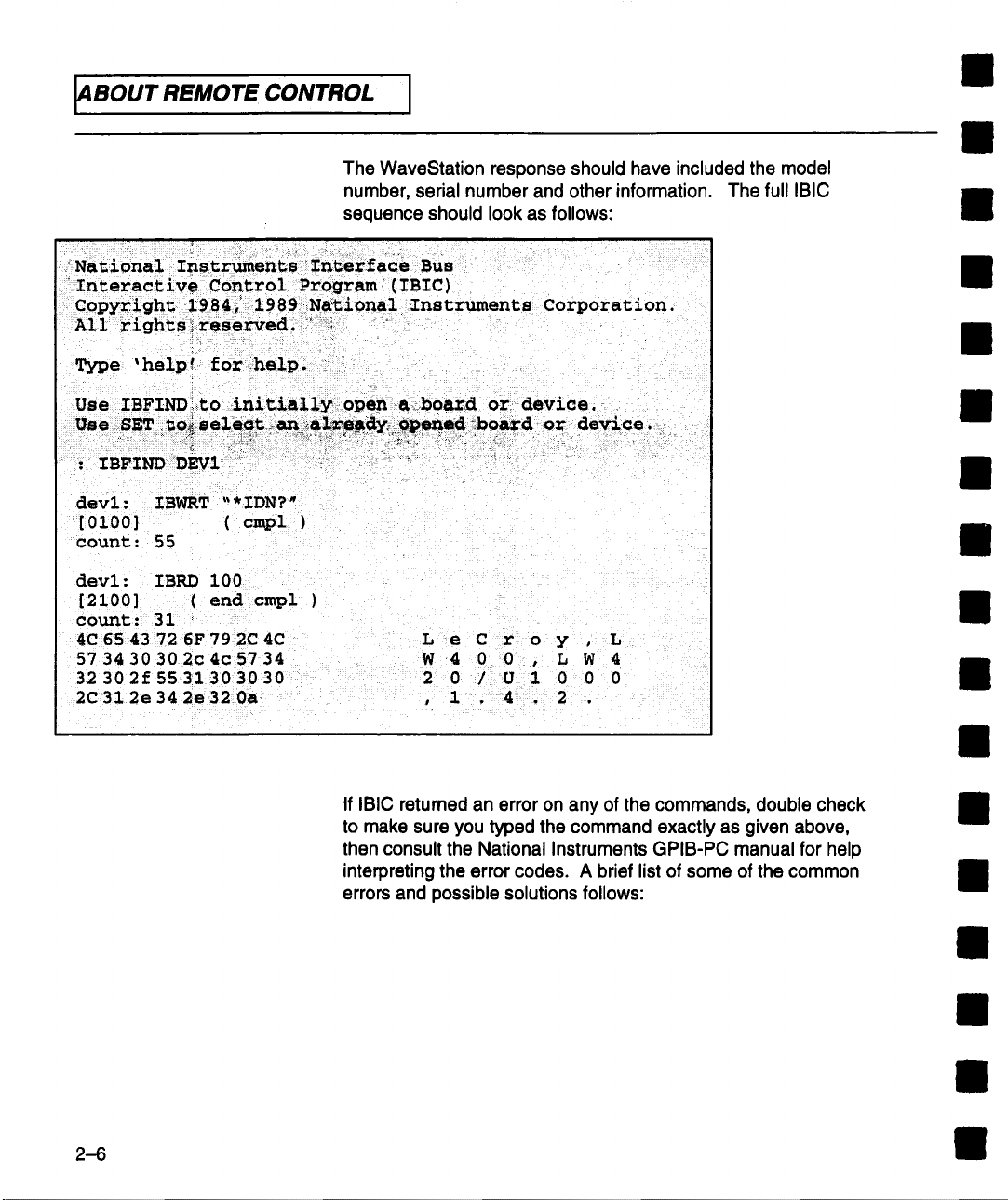
The WaveStation response should have included the model
number, serial number and other information. The full IBIC
sequence should look as follows:
National Imstruments Interface BUS
Interactive Control Program (IBIC)
Type ’ help ! for help.
: IBFIND DEVI ,
devl: IBWRT ’~* IDN?"
[0100]
count: 55
devl: IBRD 100
[2100] ( end cmpl )
count: 31
4C 65 43 72 6F 79 2C 4C
57 34 30 302c4c5734
32 302f 55 31 3030 30
2C31 2e34 2e32 0a
( cmpl
L e C r o y , L
W 4 0 0. L W 4
2 0 / U 1 0 0 0
, 1 , 4 . 2 .
2-6
If IBIC retumed an error on any of the commands, double check
to make sure you typed the command exactly as given above,
then consult the National Instruments GPIB-PC manual for help
interpreting the error codes. A brief list of some of the common
errors and possible solutions follows:
Page 19
I ABOUT REMOTECONTROL I
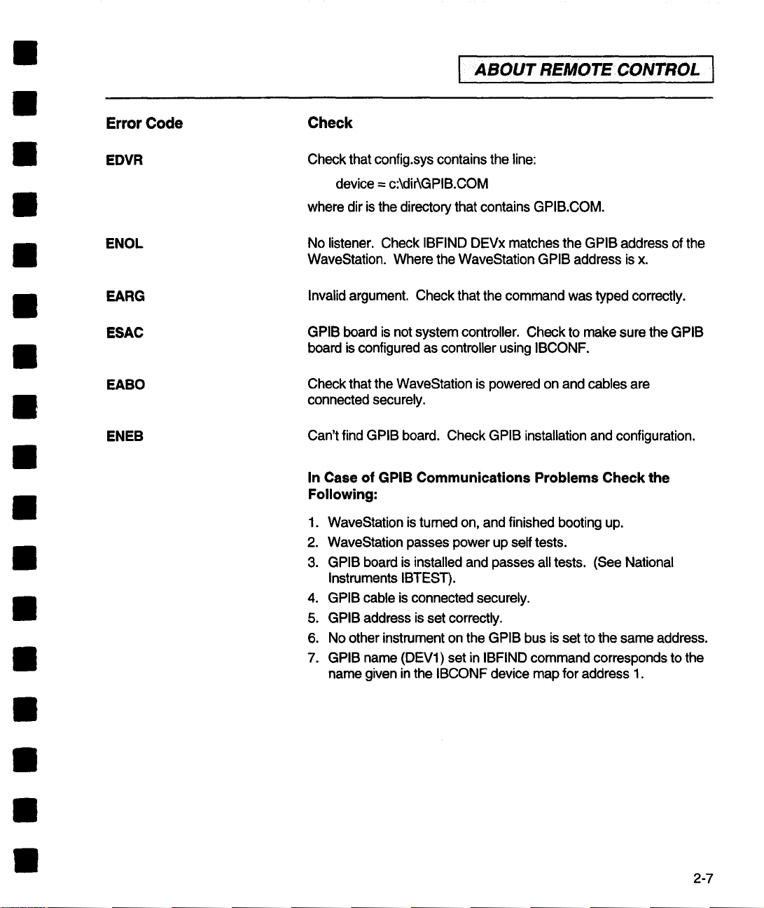
Error Code
EDVR
ENOL
EARG
ESAC
EABO
ENEB
Check
Check that config.sys contains the line:
device = c:\dirkGPIB.COM
where dir is the directory that contains GPIB.COM.
No listener. Check IBFIND DEVx matches the GPIB address of the
WaveStation. Where the WaveStation GPIB address is x.
Invalid argument. Check that the command was typed correctly.
GPIB board is not system controller. Check to make sure the GPIB
board is configured as controller using IBCONF.
Check that the WaveStation is powered on and cables are
connected securely.
Can’t find GPIB board. Check GPIB installation and configuration.
In Case of GPIB Communications Problems Check the
Following:
1. WaveStation is tumed on, and finished booting up.
2. WaveStation passes power up self tests.
GPIB board is installed and passes all tests. (See National
3.
Instruments IBTEST).
4. GPIB cable is connected securely.
GPIB address is set correctly.
5.
6. No other instrument on the GPIB bus is set to the same address.
7. GPIB name (DEV1) set in IBFIND command corresponds to the
name given in the IBCONF device map for address 1.
2-7
Page 20

4BOUT REMOTE CONTROL
~
This page left intentionally blank
2--8
Page 21

3
I
¯ 1
INSTRUMENT MODEL AND
I SUBSYSTEM
HIERARCHY
Remote Command
System Model
PROJect
It is important to understand the remote control subsystem
hierarchy in order to rapidly locate the desired command
and associated message you require. Figure 1 shows the
functional block diagram of the arbitrary waveform
generator as viewed by the remote programming interface.
The structure of the instrument subsystems is closely
related to this block diagram.
MMEMory
TRIGger
f
FGENera±or
EQUation
> BUTPu± I>
4,
]]ISPtay
I
HCIqpy
I
Figure I
Introduction to SCPI
Command Syntax SCPI commands are English language based ASCII text strings.
The SCPI command set is based on a hierarchical model of a
generic instrument. The instrument is broken down into major
system elements like OUTPUT, DISPLAY, etc. The command
follows a path from major functional elements down through
3-1
Page 22
’
Instrument Model and
Subsystem l-llerarchy
subsystems, to specific functions within the subsystem. For
example to turn on Channel l°s 1 MHz output bandwidth limit
filter the command would be:
OUTPutl:FILTer: FREQuency 1E6
The command is shown in its long (or verbose) form. As with all
commands described in this manual, the uppemase letters
indicate the characters required to represent the short form of
the command. Note that SCPI instruments are not case
sensitive, the use of capitalization in this manual is only intended
to show the difference between the long and short forms of the
command.
Note also that the short form and long form are the only
acceptable forms of a command. So, for "frequency" we can
send "freq" or "frequency" but not "frequ", for example. The
short form is the first four letters, unless the fourth is a vowel, in
which case the short form is the first three letters.
3-2
Keywords are separated by colons, while arguments use a
space as a delimiter. Multiple commands can be included in a
single multi-element command by using a semi-colon to
separate each element. Multiple elements within the same
command may be abbreviated if each element is within the
same subsystem. The second element in a multi-element
command must be preceded with a colon if it is not within the
same subsystem. Commands enclosed in square brackets
indicate default subsystems. For example, OUTPutl:STAte ON
is equivalent to OUTPut1 ON.
Page 23
Instrument Model and
Subsystem Hierarchy I
These are four valid WaveStation commands under two different
subsystems. The WAVE and OUTPut subsystems.
WAVE:SELECT chl - Enable channel 1 editor
WAVE:OPEN "new_wave" - Select waveform new_wave
OUTPut1 :FILTer:FREQuency 1 E6 - Enables the Channel 1
MHz Bandwidth filter
OUTPut1 on - Enables channel 1 output
The above commands may be sent to the WaveStation one
command at a time or they may be combined into a single multi-
element command. Following are valid forms for a multi-element
command. Each element in the command is separated by semi-
colon.
WAVE:SELECT chl ;OPEN "new_wave"
OUTPut1 :FILTer:FREQuency 1E6;:OUTPutl on
Note that when commands are combined using the semicolon
they must be at the same level in the command hierarchy. So
the second line, in the example above, cannot contain just the
argument "on", it requires that the keyword :OUTPut1 be
included. An alternative form of the combined command places
the commands in hierarchical order and doesn’t require a re-
statement of the keyword:
I
OUTPut1 on; FILTer:FREQuency 1E6
A complete discussion of SCPI command structure is contained
in "SCPI 1993, Volume 1:Syntax and Style" available from the
SCPI Consortium.
The English nature of SCPI commands often means that a
command can directly be mapped to a corresponding menu
control. Where standard commands are not available in the
1993 SCPI standard, LeCroy has extended the language to
facilitate control of the instrument. Extensions to the language
use command names and arguments that adhere to the
terminology used in the menu system wherever possible.
3-3
Page 24
Instrument Model and
I
Subsystem Hierarchy
Command Subsystems
OUTPut Subsystem
This section provides a comprehensive overview of the SCPI
command subsystems. All command keywords are shown. This
section is intended to assist the user in rapidly locating the
command form required to carry out AWG actions or query
settings and values. Commands with only a query form are
shown with a ’?’ as a suffix. Command arguments are not
described in detail in this section. Refer to Section 6 of this
manual for details of command arguments and for additional
information on the commands.
The OUTPut subsystem provides control of the output
channel(s), additive noise, and low pass filter bandwidth
selections.
Because the instrument may have two channels, the OUTPut
subsystem is controlled using OUTPut1 or OUTPut2 in order to
uniquely control each of the arbitrary waveform generator’s
outputs. In this manual, the numeric suffix to the OUTPut
subsystem is shown in general form using a # character i.e.,
OUTPut#:NOISe controls the noise output of either channel.
3-4
Page 25
Overview of OUTPut Commands
OUTPut#
[STATe]
FILTer
[LPASs]
FREQuency
NOISe
[STATe]
LEVel
PATH
Enables or disables the output for the specified channel.
Sets the bandwidth for the specified channel.
Enables or disables the addition of uncorrelated, pseudo
random noise into the specified output channel.
Sets the level of noise that is inserted into the waveform for
the specified channel.
INTERNAL or EXTERNAL. EXTERNAL = routed through
BNC’s on rear. Note: OUTPI : NOISE:PATH is functionally
coupled to OUTP2:NOISE:PA TH. Both are either internal or
external
InstrumentModeland
I
Subsystem Hierarchy I
I
OUTPut2:RESample
WAVE Subsystem
Overview of WAVE commands
WAVE
AMPLitude
AMPLitude
MEDian
VMAX
VMIN
Issues command to resample channel 2 waveform. This
command only applies to channel 2.
The WAVE subsystem controls the selection, creation, editing,
and mathematical manipulation of waveforms in the selected
waveform editor, channel 1, channel 2, or scratch pad. The
operation of the WAVE subsystem is augmented by the
FGENerator and EQUation subsystems which handle the
specialized operations associated with waveform creation.
Sets the peak-to-peak amplitude of the region between the
left and right time cursors.
Sets the median voltage level of the region between the left
and right time cursor.
Sets the maximum voltage of the region between the left and
right time cursors.
Sets the minimum voltage of the region between the left and
right time cursors.
3-5
Page 26
Instrument Model and
I
Subsystem Hierarchy
WAVE
CLOCk
DECade
FiXed
FREQuency
PREServe
ACSet
LIMit
MAX
WAVE
CUT
COPY
DELete
EXTRact
Selects the clock decade in which the internal clock runs.
Selects whether the clock is fixed or variable.
Sets the frequency of the clock.
POINTS or TIME. Affects the operation of CLOCK:DECADE.
Preserve points keep data unchanged; preserve time
resamples to keep output timing the same, if possible.
Selects auto clock set mode or manual.
Selects/deselects option to limit clock to internal filters.
With LIMit set to Yes, MAX selects the clock decade in which
the internal clock runs.
Copies the region between the right and left time cursors to
the cut buffer.
Deletes the data between the left and right time cursors,
stores it to the cut buffer.
Copies the value of the waveform minus the value of the
baseline to the cut buffer.
WAVE
DATA
INSert
3-6
PREamble
MODE
PASTe
[IMMediate]
COUNt
CURSor
WRAP
Transfer waveform in Data Interchange Format (DIF) to
from host computer.
Transfer waveform DIF preamble to or from host computer.
Selects insert or overwrite insertion mode.
Inserts the contents of the cut buffer into the waveform.
Sets the insert repetition count, i.e, number of times the
contents of the cut buffer is inserted into the waveform.
Selects if waves are inserted before or after the cursor.
Selects if waveform is to be continuous with the last point
wrapped to first or if waveform is single shot.
Page 27

WAVE
INSert
SCOPe
[IMMediate]
ADDRess
BWLimit
CONTrol
PREServe
SOURce
TYPE
SHAPe
DC
PULSe
RAMP
DURation
LEVel
AMPLitude
BASE
CYCLes
ETIMe
PERiod
TDELay
WIDTh
AMPLitude
CYCLes
FREQuency
INVert
OFFSet
SPOSition
Instrument Model and I
I
Subsystem Hierarchy I
Downloads the data from the specified digital oscilloscope
(DSO).
Sets the GPIB address of the source DSO.
Select option to check for and correct waveform
discontinuities or to not check or correct discontinuities.
Selects the GPIB request control mode for DSO transfers.
Sets how the data from the digital oscilloscope is preserved.
The data can be preserved in time or by points.
Selects waveform source from available DSO traces.
Selects DSO type (model),
Set the time duration (length) of the inserted DC function.
Set the voltage level of the inserted DC function.
Sets the base to top amplitude of the standard wave pulse.
Sets the base voltage level of the pulse.
Sets the number of pulse cycles inserted into the waveform.
The 10%-90% transition time of the rising and falling edges
of the standard wave pulse.
Sets the period (1/frequency) of the standard wave pulse.
Sets time delay from the beginning of the waveform and the
beginning of the first edge of the pulse.
Sets the half amplitude width of the standard wave pulse.
Sets the peak-to-peak amplitude of the standard wave ramp.
Sets the number of cycles of the standard wave ramp
inserted into the waveform.
Sets the frequency of the standard wave ramp.
Controls the polarity of the ramp’s slope, i.e. rising or falling.
Sets the voltage of the zero degree phase of the ramp."
Sets the start position of the ramp in percentage of the ramp
amplitude.
3-7
Page 28
lnstrument Model and
l
Subsystem l-llerarchy
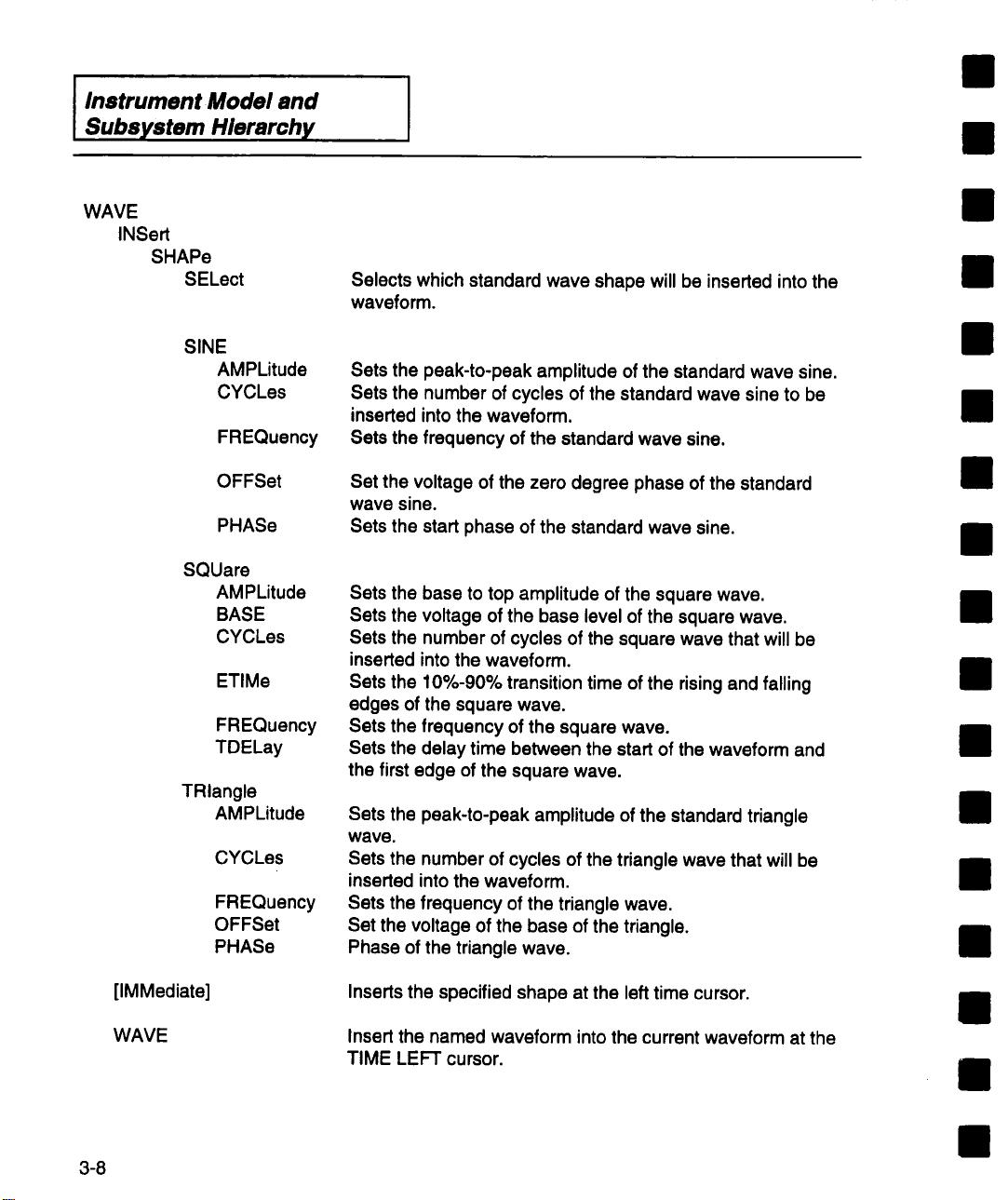
WAVE
INSert
SHAPe
SELect
SINE
AMPLitude
CYCLes
FREQuency
Selects which standard wave shape will be inserted into the
wave form.
Sets the peak-to-peak amplitude of the standard wave sine.
Sets the number of cycles of the standard wave sine to be
inserted into the waveform.
Sets the frequency of the standard wave sine.
SQUare
TRiangle
[IMMediate]
OFFSet
PHASe
AMPLitude
BASE
CYCLes
ETIMe
FREQuency
TDELay
AMPLitude
CYCLes
FREQuency
OFFSet
PHASe
Set the voltage of the zero degree phase of the standard
wave sine.
Sets the start phase of the standard wave sine.
Sets the base to top amplitude of the square wave.
Sets the voltage of the base level of the square wave.
Sets the number of cycles of the square wave that will be
inserted into the waveform,
Sets the 10%-90% transition time of the rising and falling
edges of the square wave.
Sets the frequency of the square wave.
Sets the delay time between the start of the waveform and
the first edge of the square wave.
Sets the peak-to-peak amplitude of the standard triangle
wave.
Sets the number of cycles of the triangle wave that will be
inserted into the waveform.
Sets the frequency of the triangle wave.
Set the voltage of the base of the triangle.
Phase of the triangle wave.
Inserts the specified shape at the left time cursor.
3-8
WAVE
Insert the named waveform into the current waveform at the
TIME LEF’r cursor.
Page 29

WAVE
MARKer
MATH
CLOCk
FIRSt
FREQuency
EDGE
DEFault
NDEFined
TIME
[STATE]
LEVel
TYPE
COUPling
IMMediate
SOURce2
[OPERation]
Instrument Model and
I
Subsystem Hierarchy
Sets the time at which the first edge of the clock marker
begins. WAVE:MARKer:TYPE must be set to CLOCk.
Sets the frequency of the marker clock.
WAVE:MARKer:TYPE must be set to CLOCk."
Sets default edge marker.
Query only. Number of edges defined.
Sets the time at which STATE will act.
Low or High.
Sets the voltage level of the marker to TTL or ECL levels.
Selects either a clock marker or an edge marker.
AC or DC, used only for INTEGRATION. If DC, integration of
a constant non-zero voltage becomes a ramp.
Performs the math function specified by
WAVE:MATH[:OPERation] on the current waveform and
WAVE:SOURce2 (if applicable) on the region between the
left and right time cursors. The result is placed into the
current waveform.
Name of the "other" waveform for two waveform operations
such as ADD, SUBTRACT, MULTIPLY DIVIDE.
Specifies which math operation will be performed by
WAVE:MATH :lMMedate. Operation can be SMOOTH, ADD,
SUBTract, MULTiply, DIVide, INTegrate DIFFerentiate
CONVolve.
NEW
OPEN
REGion
LEFT
RIGHt
Creates a new waveform with the name specified by the
argument.
Opens a waveform from the current project.
Set the position of the left time cursor.
Set the position of the right time cursor. This command
requires time cursors not to be in the track mode.
3-9
Page 30
Instrument Model and
Subsystem Hierarchy
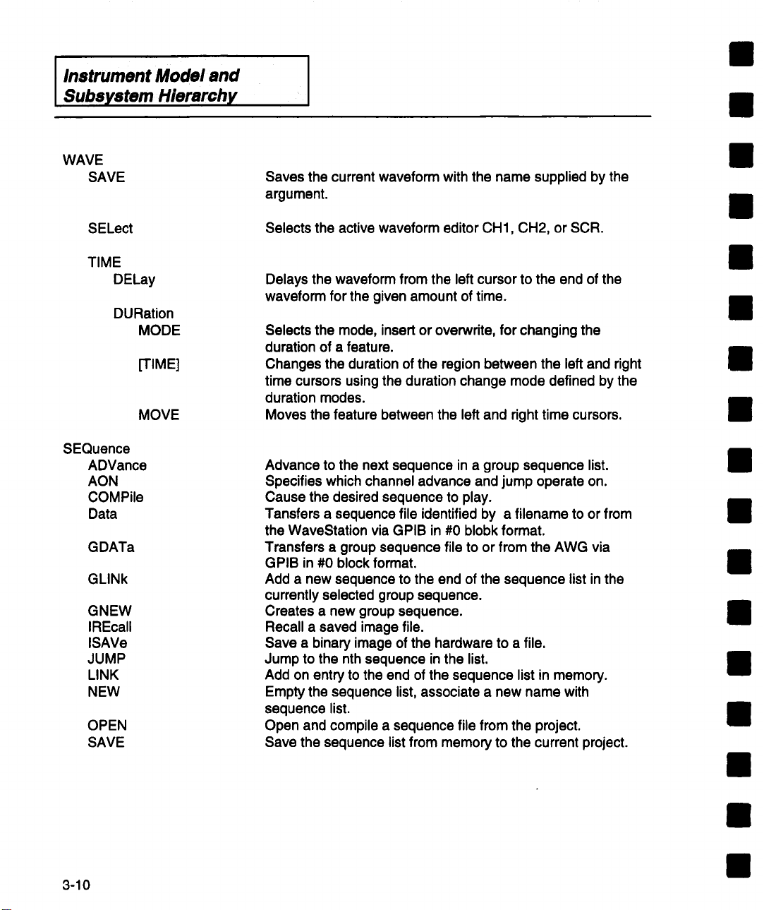
WAVE
SAVE
Saves the current waveform with the name supplied by the
argument.
SELect
TIME
DELay
DURation
SEQuence
ADVance
AON
COMPile
Data
GDATa
GLINk
GNEW
IREcall
ISAVe
JUMP
LINK
NEW
OPEN
SAVE
MODE
[TIME]
MOVE
Selects the active waveform editor CH1, CH2, or SCR.
Delays the waveform from the left cursor to the end of the
waveform for the given amount of time.
Selects the mode, insert or overwrite, for changing the
duration of a feature.
Changes the duration of the region between the left and right
time cursors using the duration change mode defined by the
duration modes.
Moves the feature between the left and right time cursors.
Advance to the next sequence in a group sequence list.
Specifies which channel advance and jump operate on.
Cause the desired sequence to play.
Tansfers a sequence file identified by a filename to or from
the WaveStation via GPIB in #0 blobk format.
Transfers a group sequence file to or from the AWG via
GPIB in #0 block format.
Add a new sequence to the end of the sequence list in the
currently selected group sequence.
Creates a new group sequence.
Recall a saved image file.
Save a binary image of the hardware to a file.
Jump to the nth sequence in the list.
Add on entry to the end of the sequence list in memory.
Empty the sequence list, associate a new name with
sequence list.
Open and compile a sequence file from the project.
Save the sequence list from memory to the current project.
3-10
Page 31

Instrument Model and
I
Subsystem Hierarchy I
FGENerator Subsystem
Overview of FGEN Commands
FGENerator#
DC
LEVel
MULTitone
AMPLitude
NTONes
OFFSet
TONE#
RAMPlitude
[FREQuency]
PULSe
AMPLitude
BASE
ETIMe
PERiod
SWEep
SPACing
STARt
STOP
TIME
[STATe]
The WaveStation’s standard function generator mode is
controlled by the FGENerator subsystem. Any of the seven
standard waveforms, sine, triangle, square, ramp, pulse,
multitone, and DC can be specified. Key parameters such as
frequency, amplitude, offset, and start phase can be controlled
directly. Additionally, the frequency of the sine, triangle, square,
ramp and pulse waveforms can be swept linearly or
logarithmically.
Set the DC voltage level for the specified channel’s function
generator (either I or 2).
Sets the peak-to-peak amplitude of the multitone function in
the specified channel’s function generator (either 1 or 2).
Sets the number of tones to be calculated for the multitone function.
Set the voltage of the zero degree phase of the multitone
waveform.
Sets the relative amplitude of the current tone in the
multitone waveform.
Set the frequency of the current tone in the multitone
waveform.
Sets the base to top amplitude of the pulse in the specified
channel’s function generator (either 1 or 2).
Sets the voltage of the base level of the pulse waveform in
the specified channel’s function generator (either 1 or 2).
Sets the 10%-90% edge time of both the rising and falling
edges of the pulse waveform.
Sets the period (1/frequency) of the pulse in the specified
channel’s function generator (either 1 or 2).
Selects the type of sweep (either linear or log) in the
specified channel’s function generator (either 1 or 2).
Sets the start frequency of the sweep.
Sets the stop frequency of the sweep.
Sets the sweep duration.
Turns the sweep on or off.
3-11
Page 32

Instrument Model and
I
Subsystem Hierarchy
FGENerator#
PULSe
TDELay
WIDTh
RAMP
AMPLitude
FREQuency
INVert
OFFSet
SPOSition
SWEep
STARt
STOP
TIME
[STATe]
Sets the amount of time between the beginning of the
waveform and the beginning of the first edge of the pulse.
Sets 1he width of the pulse from 50% up the rising edge to
50% down the falling edge.
Sets the peak-to-peak amplitude of the ramp in the specified
channel’s function generator (either 1 or 2).
Sets the frequency of the ramp.
Controls whether the ramp is rising or falling.
Set the median voltage of the ramp waveform.
Sets the start position of the ramp in percentage of the
ramp’s peak-to-peak amplitude.
Sets the start frequency of the sweep.
Sets the stop frequency of the sweep.
Sets the sweep duration.
Turns the sweep on or off.
3-12
SELect
SINE
AMPLitude
FREQuency
OFFSet
PHASe
SWEep
SPACing
STARt
STOP
TIME
[STATe]
Selects which function the specified channel’s function
generator outputs. The available functions are: SINE,
TRiangle, SQUare, RAMP, PULSe, MULTitone, and DC.
Sets the peak-to-peak amplitude of the sine wave in the
specified channel’s function generator (either 1 or 2).
Sets the frequency of the sine wave.
Sets the voltage of the zero degree phase of the sine
waveform.
Sets the start phase of the sine wave.
Selects the sweep type (either linear or log).
Sets the start frequency of the sweep.
Sets the stop frequency of the sweep.
Sets the sweep duration.
Turns the sweep on or off.
Page 33

FG ENerator#
SQUare
AMPLitude
BASE
ETIMe
FREQuency
SWEep
SPACing
STARt
STOP
TIME
[STATe]
TDELay
TRiangle
AMPLitude
FREQuency
OFFSet
PHASe
SPACing
SWEep
STARt
STOP
TIME
[STATe]
InstrumentModel and
Subsystem Hierarchy I
I
Sets the peak-to-peak amplitude of the square wave in the
specified channel’s function generator (either I or 2).
Sets the voltage of the base level of the square wave.
Sets the 10%-90% edge time of both the rising and falling
edges of the square wave.
Sets the frequency of the square wave.
Selects the sweep type (either linear or log).
Sets the start frequency of the sweep.
Sets the stop frequency of the sweep.
Sets the sweep duration.
Turns the sweep on or off.
Sets the amount of time between the start of the waveform
and the first edge of the square wave. Useful in single trigger
mode; in continuous this time lowers the frequency.
Sets the peak-to-peak amplitude of the triangle wave in the
specified channel’s function generator (either 1 or 2).
Sets the frequency of the triangle wave.
Sets the median voltage of the triangle waveform.
Sets the start phase of the triangle wave.
Selects the sweep type (either linear or log).
Sets the start frequency of the sweep.
Sets the stop frequency of the sweep.
Sets the sweep duration.
Turns the sweep on or off.
[STATe]
Turns the function generator on or off in the specified
channel (either I or 2).
3-13
Page 34

Instrument Model and
I
Subsystem, Hierarchy
EQUation Subsystem The equation subsystem is used to enter, select, save, and
recall equations which describe waveforms mathematically. It is
also used to calculate the waveform sample values based on
the equation.
Overview of EQUation Commands
EQUation
CALCulate
DATA
DEFine
DURation
LINE
NEW
OPEN
SAVE
Calculates the currently specified equation line for the preset
duration and inserts it into the current waveform at the left
cursor position using the current insert mode.
Transfers all the lines of the equation sheet as a "#0" block.
#0 is an indefinite length block of data terminated with EOI.
Defined in IEEE 488.2.
Defines an equation for the current equation line. The
equation line may be up to 50 characters in length and must
be surrounded by quotes. Valid functions are: SIN, COS,
SQRT, PULSE, STEP, LN, LOG, ABS, EXP and TAN. Valid
operators are: +, -, *,/, (,), "","", = and ^. Valid variable
names are X1 through X16. Valid arguments are T, PI,
NOISE, and GNOISE.
Sets the time span over which the equation will be
calculated.
Selects an equation line from the current equation sheet.
Creates a new equation sheet.
Opens an existing equation sheet.
Saves the current equation sheet.
3-14
Page 35

InstrumentM°deland
I
Subsystem Hierarchy I
DISPlay Subsystem The DISPlay subsystem controls the selection and
presentation of text, graphics and waveform information. In
addition, the cursor system is controlled by this subsystem.
Overview of DiSPlay Commands
DISPlay
ANNotation
DATE[:STATe]
LOGO[:STATe]
PARameter[:STATe]
[ALL]
SSAVe Allows the automatic screen saver to be enabled or disabled.
[WINDow]
TRACe
ALL
COLor
CURSors
TIME
DELTa
LEFT
RIGHt
SALL
TEND
TGRid
TRACk
[STATe]
VOLTage
BOTTom
DELTa
TGRid
Allows the time/date annotation field to be switched on or off.
Allows the Company Logo to be switched on or off.
Turns the parameters readouts on or off.
For SCPI compatibility. Same as "Logo".
Displays the whole waveform on the screen.
Sets the trace intensity. Setting the intensity for one trace
will set the same intensity for all traces.
Change the delta time between the time cursors. This
command only has effect if the cursors are in the track mode.
Set the position of the left time cursor.
Set the position of the right time cursor. This command only
has effect if the cursor track mode is off.
Select All selects the entire waveform by placing the left
cursor at time zero and the right cursor at the end of the
waveform.
Places both cursors at the end of the waveform.
Moves both time cursors so they are on the display.
Enables or disables time cursor tracking.
Turns the time cursors on or off.
Set the position of the bottom voltage cursor.
Change the delta voltage between the voltage cursors. This
command only has effect if the voltage cursors are in the
track mode.
Moves both voltage cursors so they are on the display.
~
[
3-15
Page 36

lnstrument Model and
I
Subsystem Hierarchy
DISPlay
[WINDow]
TRACe
VOLTage
TOP
TRACk
[STATe]
GRATicule
COLor
GRID
[STATe]
TYPE
TRACe
X[:SCALe]
CENTer
PDIVision
TCURsors
Y[:SCALe]
PDIVision
RLEVel
Sets the position of the top voltage cursor. This command
only has effect if track is off.
Enables or disables voltage cursor tracking.
Turns the voltage cursors on or off.
Set the display intensity for the grid.
Select or query the grid style. The grid may be a full grid
(ON), no grid (OFF), or set to a cross hair (CHAir).
Selects the type of grid to display. Single, dual, SXY, XY.
Sets the time at the horizontal center of the grid.
Sets the horizontal time per division of the grid.
Displays the portion of the waveform between the time
cursors with the left cursor one division from the left edge of
the grid and the right cursor one division from the right edge
of the grid.
Sets the vertical volts per division of the grid.
Sets the voltage at the vertical center of the grid.
3-16
ZPRevious
Restores the zoom settings to the previous time and voltage
zoom settings.
Page 37

Instrument Model and I
I
HCOPy Subsystem The HCOpy subsystem provides control over printing and
output of screen graphics form the WaveStation.
Overview of HCOPy Commands
HCOPy
AUToincr
FILename
INDex
TARGet
GRAPhics
DESTination
FORMat
PRINter
DESTination
FFEed
MODel
QUALity
SIZE
Enables automatic increment of the filename index when a
hardcopy is stored to a file.
Set or query the current hardcopy file name.
Set the hardcopy filename index number. The index may
range from 0 to 999.
Set the destination for the hardcopy graphics file.
Set the hardcopy graphics file format.
Set the destination of the hardcopy printer data. The
destination may be the GPIB or Centronics port, or it may be
the floppy disk drive where a file in printer format will be
stored.
Set whether a form feed is automatically generated following
a hardcopy.
Set the specified printer model.
Set the print quality, draft or proof. This setting is not
available for all supported printers.
Set the size of the hardcopy, notebook or presentation.
Subsystem Hierarchy
TYPE
[IMMediate]
Sets the hardcopy format. Hardcopies may be formatted to
provide data suitable for printers or graphics files.
Begin a hardcopy.
3-17
Page 38

lnstrument Model and
l
Subsystem l-llerarchy
TRIGger Subsystem
Overview of TRIGger Commends
INITiate [:IMMediate]
TRIGger[:SEQuence]
BCOunt
DELay
LEVel
MODE
SLOPe
SOURce
The trigger subsystem is used to control the Trigger section
of the AWG. This includes controls for triggering such as
level, mode, source and slope.
Triggers the system, equivalent to the IEEE 488.2 command
*TRG.
Sets the burst count or number of repetitions of the waveform
that will be output after a trigger is received in burst mode.
Sets the delay from trigger to start of output of the waveform.
Sets the trigger level in volts.
Sets the trigger mode. The trigger mode may set to
CONTinuous, SINGle, BURSt, or GATE.
Sets the trigger slope.
Sets the trigger source. The trigger source may internal or
external.
3-18
Page 39

InstrumentModel and
Subsystem Hierarchy
MMEMory Subsystem
Overview of MMEMory Commands
MMEMory
CATalog
EQUation
IMAGe?
SEQuence
WAVeform
[ALL]
DATA
PREamble
DELete
EQUation
IMAGe
PROJect
SEQuence
[WAVe form]
The MMEMory (mass memory) subsystem provides support
for the extensive hard disk storage capability of the
WaveStation.
Returns a list of all equations in the current project.
Returns a listing of image files located in the current project
Retums a list of all sequences in the current project.
Returns a list of all waveforms in the current project.
Returns a list of all objects in the current project.
Upload or download the waveform named in the associated
argument. Waveforms are stored in DIF format.
Upload or download the header of the waveform named in
the associated argument.
Deletes the named equation.
Deletes the named image.
Deletes the named project.
Deletes the named sequence.
Deletes the named waveform.
3-19
Page 40

Instrument Model and
I
Subsystem Hierarchy
PROJect Subsystem
Overview of PROJect Commands
PROJect
NEW
OPEN
SAVE
The project subsystem is used to create, open, and save
individual user work areas called projects.
Creates a new project with the specified name. The current
project is closed and the new project is created.
Opens the specified project if it exists (no action is taken if it
doesn’t exist) and closes current project.
Saves the current project.
3-20
Page 41

Instrument Model and
I
Subsystem Hierarchy
SYSTem Subsystem
Overview of SYSTem Commands
SYSTem
CLOCk
EREFerence
COMMunicate
GPIB[:SELF]
ADDRess Sets the GPIB address of the AWG.
ERRor?
HELP
SYNTax?
VERSion?
Provides controls not specific to the vertical, horizontal,
trigger, or measurement subsystems.
Sets whether the system uses the internal clock reference or
an external 10 MHz clock reference.
Query the last three system errors. The result of the query is
the error number followed by the error text for each of the
last three system errors.
Finds out the arguments for and full form of a header.
Example, SYST:HELP:SYNTAX? "WAVE:OPEN".
Returns SCPI version number for which instrument complies.
CALibration Subsystem
CALibration[:ALL]?
Performs an Internal calibration and returns a status code
indicating if the calibration was successful:
0 = Calibration successful
1 = Calibration failed
3-21
Page 42

lnstrument Model and
l
Subsystem Hierarchy
STATus Subsystem
Overview of STATus Commends
STATus
OPERation
CONDition?
ENABle
[EVENt]?
PRESet
The status Subsystem is used to control the status reporting
registers. This includes the 488.2 specified condition, event
and enable registers as well as the SCPI defined
QUEStionable and OPERation registers. There are two
event status registers, the Status Byte Register (STB) and
the Standard Event Status Register (ESR) within the
WaveStation. There are also two dual purpose (event and
condition) registers: the OPERation Status Register and the
QUEStionable Status Register. Finally there is an
Error/Event queue that records the last error. For full
information on the Status Registers, please refer to Section 4
of this manual.
Query the Operation Status Condition Register.
Enable bits in the Operation Status Event Register that will
be summarized in the Status Byte Register.
Query the contents of the Operation Status Event register.
Clear all status registers and clear all enable registers. Sets
enable registers to the same as power on conditions.
QUEStionable
CONDition?
ENABle
[EVENt]?
3-22
Query the Questionable Status Condition Register.
Enable bits in the Questionable Status Event Register that
will be summarized in the Status Byte Register.
Query the Questionable Status Event Register.
Page 43

lnstrumentModel and I
I
Subsystem Hierarchy I
488.2 common Commands
*CAL?
*CLS
*ESE
*ESR?
*IDN?
*LRN?
*OPC?
*OPC
*PCB
In addition to the SCPI subsystems, 488.2 mandatory are
supported by the WaveStation. Following is a brief listing of
the standard 488.2 commands. The 488.2 commands work
in combination with the SCPI commands to provide full
control of the WaveStation.
Performs a system calibration and returns a status code
indicating if the calibration was successful:
0 = Calibration successful
1 = Calibration failed
Clears all status registers.
Enable bits in the Event Status Register.
Reads and clears the contents of the Event Status Register.
Identifies the instrument. The response indicates the
manufacturer, the model, the serial number and the software
revision level.
Read the current instrument setup.
When overlapped operations are complete place a "1’ into
the output queue.
When overlapped operations are complete assert the OPC
bit in the EVENT STATUS register.
Identifies the address to pass control back to when the
WaveStation is about to be given control of the GPIB bus.
*RST
*SRE
*STB?
*TRG
*TST
*WAI
Sets all settings (1/O and Scope setup) to their default values.
Enable bits in the Service Request Enable mask.
Read the contents of the main status byte.
Same as the manual button on the Trigger menu.
Performs selftest and returns a status code indicating if
selftest was successful: 0 = success.
WAIT for completion of overlapped operations before parsing
more commands. The operations under WAVE:TIME, and
SEQ:COMP.LC are overlapped operations.
3-23
Page 44

Instrument Model and
I
Subsystem Hierarchy
This page left intentionally blank
3-24
Page 45

4
STATUS&ERROR
I
REPORTING t
I
Status Register
Status Byte Operation
Status Data Structures
Register Model
A set of status registers allows the user to quickly determine the
AWG’s internal processing status at any time. The status registers
as well as the status and event reporting system adhere to the SCPI
recommendations.
The WaveStation continually updates its status to report the latest
events, conditions, and settings.
Changes are summarized by designated bits in the Status Byte
register (STB). The seventh bit, RQS, is asserted whenever any
other bits in the STB are reported as set and their corresponding
enable bits are set. Also, whenever the RQS bit is set, the GPIB bus
SRQ line is automatically asserted.
In general, an asserted bit in the main status byte (STB) reflects,
summarizes, a change in a corresponding status register or queue
(i.e. Standard Event Status Register, Questionable Status Register,
Operation Status Register, or Error/Event Queue).
Two types of status structures, the Register (individual bits) and the
Queue (encoded number), are used in the WaveStation.
In the Register Model individual bits identify a specific WaveStation
condition or event.
Queue Model
Altematively, each bit could act as a summary bit for an associated
status register. Using bits in one status register to indicate changes
in other registers allows for a layered status description. This layering
of detail enables the controller to limit the amount of information it
receives. The Status Byte Register, Standard Event Status Register,
Questionable Status Register, and Operation Status Register all use
the register model status structure.
The Queue Model is a single register which contains an encoded
number. For example, this number may be an error code which
corresponds to an error condition.
4-1
Page 46

I Status & Error Reporting
Event Recording IEEE-488.2 allows two ways to record an event and the WaveStation
Condition Registers Condition Registers are updated continually and are not cleared
I
The WaveStation’s Error/Event Queue is the only register in the
WaveStation employing the queue model. The Error/Event Queue
can hold one error code. When read, the queue reports the most
recent error code, and clears itself.
When the queue is cleared (empty), the corresponding bit in the
Status Byte Register will be cleared. Conversely, when the queue
contains an error code, the corresponding bit in the Status Byte
Register will be set.
registers are implemented as both condition and event registers to
provide full functionality. The names of the condition and event
registers are the same. Only the commands to query the event and
condition registers differ.
when read. If a condition was true but is no longer true the
corresponding bit in the condition register will be false. The
WaveStation has only two condition registers, the Questionable
Status Register and the Operational Status Register. These two
registers also function as event registers. Whether the condition or
event register is queried depends on the form of the query used.
Event Registers Event Registers capture changes in conditions. They are not cleared
until they are read, even if the condition which caused the event no
longer exists. All registers in the WaveStation function as event
registers. The Questionable Status Register and Operational Status
Register function as both event and condition registers depending on
how they are queried. Each bit in an Event Register either
summarizes an event register, or reports a condition or event in the
WaveStation. A bit is set to true (1) when the summary, condition,
event changes from false (0) to true (1) and will remain set until
cleared using the *CLS command or by reading the register.
4-2
Page 47

I Status & Error Reporting I
Querying the Operational
and Questionable Status
Register
Since the Operational Status Register and the Questionable
Status Register can be both condition and event registers
depending on the query form the query form is very important.
To read the Operational and Questionable Event Registers
use the following commands:
STATus:OPERation? - Read Operation Status Event Register.
STATus:QUEStionable? - Read Questionable Status Event Register.
To read the Operation and Questionable Condition Registers use the
following commands:
STATus:OPERation:CONDition? - Read Operation Status Condition
Register.
STATus:QUEStionable:CONDition? - Read Questionable Status
Condition Register.
The following example illustrates how the condition and event
registers can retum different values.
The waiting for trigger status is shown in bit 5 of the Operation Status
register. (The bit meaning of each bit in each register is documented
later in this section.)
While the WaveStation is waiting for a trigger, the commands
STATus:OPERation? and STATus:OPERation:CONDition? retum
the same value for bit 5. Both commands retum true (32) because
the WaveStation is waiting for a trigger.
If both commands are issued again, while the WaveStation is still
waiting for a trigger, the results will be different. The command
STATus:OPERation? will return false (0) because it was cleared
when the event register was read with the command above. The
command STATus:OPERation:CONDition? will retum true (1)
4--3
Page 48

I Status & Error Reporting
because it was not cleared when read and the WaveStation is still
waiting for a trigger.
When the waveform is being generated, the command
STATus:OPERation? will retum false (0) because the event register
was read and cleared the first time the command was sent. The
command STATus:OPERation:CONDition? will return false (0)
because the WaveStation is not waiting for a trigger..
If the WaveStation was waiting for a trigger, receives a trigger and
we send the query STATus:OPERation? While the waveform is
being generated, then this query will return true (32) because the
event of waiting for trigger has occurred since the event register was
last cleared. The query STATus:OPERation:COND? Will retum
false (0) because the WaveStation is not currently waiting for
trigger.
Event Enable Registers
The WaveStation registers are arranged in a tree like structure. The
Status Byte Register is the root of the structure and branches out to
summarize the Standard Event Status Register, the Operation
Status Registers, the Questionable Status Register, and the
Error/Event Queue. Coupled with each event register is an Enable
Register. The Enable Registers determine which if any bits of the
associated Event Register will be summarized in the Status Byte
Register.
Each bit in an event enable register is "AND’ed" with its
corresponding bit in its associated status event register. If the result
of the AND operation is a one (true) the summary bit will be set in the
Status Byte Register.
All event registers are edge sensitive, meaning they are set when the
status changes state. The SCPI standard allows for choosing the
edge of interest (positive going or negative going), but this capability
is not implemented in the WaveStation. The WaveStation will set
the bit in the status register to true (1) whenever the status changes
from false (0) to true (1). Event register bits are set on a positive
going transition.
4-4
Page 49

I Status & Error Reporting I
The status registers and enable registers are associated as follows:
Status Byte Register
Standard Event Status Register
Operation Status Register
Questionable Status Register
Service Request Enable Register
Event Status Enable Register
Operation Status Enable Register
Questionable Status Enable
Register
The following commands are used to set the value of the enable
registers:
*SRE
*ESE
STATus:OPERation: ENABle
STATus:QUEStionable:ENABle
Service Request Enable Register
Event Status Enable Register
Operation Status Enable Register
Questionable Status Enable
Register
The enable registers for the Operation Status Register and the
Questionable Status Register are 15 bits wide with each bit
selecting a different condition or event. The enable registers for
the Service Request Register and the Event Status Register are
7 bits wide with each bit selecting a different condition or event.
The bit positions for the enable register match the bit positions
for the status registers and have the same names. While the
Operation Status Register and the Questionable Status Register
can function as both event and condition registers, only the
results of the event register are AND’ed with the enable register
to set the summary bit in the Status Byte Register.
The value of the Enable registers may also be changed to a
preset value with the STATus:PREset command.
STATus:PREset clears the Operation and Questionable Enable
registers. Refer to command details for STATus:PREset for the
further information. During power-on the enable registers are
set to their STATus:PREset states. The *RST and *CLS
commands have no effect on the enable registers.
4--5
Page 50

I Status & Error Reporting
Status Byte Register
Definition
Status Byte Register
Definition
Bit#
7 (MSB)
6
5
4
3
2
1
0 (LSa)
The main Status Byte register (STB) reflects instrument status at the
time it is read. The register is read when the system controller
(remote computer) polls the WaveStation with the *STB? command
or with a serial poll. Bits in the STB summarize all the other status
registers.
The STB is read with the command *STB? or by serial polling the
WaveStation. The Status Byte Registers enable register is set with
*SRE n. The Status Byte Enable Register is read w#h *$RE?. (Note:
n is the sum of the decimal bit weights of all bits that are true.)
The *STB? query does not alter any bits in the status byte. Only
the *CLS command can clear the status byte, except for the MAV
Message Available but which depends on the state of the output
queue.
Associated Status Register
Operation Status Register
none
Standard Event Status Register
MAV
Questionable Status Register
Error/Event Queue
none
none
Significance
Summarizes Operation Status Register
RQS (service request) Bit
Summarizes Standard Event
Message Available
Summarizes Questionable Status
Register
Error/Event Bit
Not Used
Not Used
Bit0: Not Used
Blt1: Not Used
Bit2: Error/Event Queue Blt
4-6
This bit is not used by the WaveStation and has no significance.
This bit is not used by the WaveStation and has no significance
The Error/Event Queue can hold three error codes. When the queue
contains an error code, bit 2 is true (1). When the queue is cleared
(empty), the corresponding bit 2 is false (0). This bit will sense
an error has occurred. To read the error code from the Error/Event
Queue the queue must be read using the SYSTem:ERRor?
command.
Page 51

Bit 3: Questionable
Status Summary Bit
Bit 4: MAV - Message
Available Bit
Bit 5: Standard Event Status
Summary Bit
I Status & Err°r Rep°rtin9 I
If this bit is true (1) it indicates that an event has caused one of the
enabled bits in the Questionable Status register to become true. To
determine the reason that caused the questionable status query the
Questionable Status Register using the STATus:QUEStionable?
command. Further documentation is available in the section on the
Questionable Status Register.
MAV is set if data is in the output queue. It is reset once the output
queue is empty. This condition bit is not set or reset when the system
controller reads STB. Also, the *CLS command does not affect this
bit.
The ESB is set if one of the bits in the ESR which is enabled in the
ESE becomes set. This bit summarizes the Event Status Register
(*ESR).
The *ESR identifies the type of event. Since the *ESR is an Event
Register, any bits stay set until the register is read. After it is
read, all the bits are cleared. Once cleared, its summary bit (bit
5) in the STB is also cleared.
*ESR’s event enable register, or mask is *ESE. To set the *ESE
use *ESE n, and to read it use *ESE?. The command to read the
*ESR is *ESR?.
Further documentation is available in the section on the Standard
Event Status Register.
Bit 6: RQS - Request
Service Bit
Bit 7: Operation Status
Summary Bit
The RQS bit is the summary bit for the other bits in the STB byte. For
GPIB, an SRQ interrupt is generated when the RQS bit is set. The
RQS bit is set when a bit in the STB is set and the corresponding bit
in the Status Byte Enable Register (SRE) is set.
If this bit is true (1) it indicates that an event has caused one of the
bits in the Operation Status register to become true. In the
WaveStation this indicates that the WaveStation is waiting for a
trigger. To determine what caused the Operation Status bit to be set,
query the Operation Status Register using the STATus:OPERation?
command. Further documentation is available in the section on the
Question Status Register.
4--7
Page 52

I Status & Error Reporting
Standard Event Status
Event Status Register Bit
Assignments
Register Definition The Standard Event Status Register
reports error conditions common to most automatic test
equipment. The WaveStation uses these bits for error reporting
and synchronization. The Standard Event Status Register is read
and cleared using the *ESR? command. The register may also
be cleared without being read using the *CLS command. Each
of the bits in the Event Status Register will be summarized in bit
5 of the Status Byte Register provide the bits are set in the Event
Status Enable register. For example to have only the operation
complete bit of the Event Status Register summarized in the
Status Byte register using the following command to enable only
the operation complete bit (bit 0):
*ESE 1 - where 1 is the decimal value when bit 0 is set (true) and
all other bits are not set (false).
BIT # Associated Significance
Status Byte
7 none
6 none
5 none Command Error
4 none Execution Error
3 none
2 none
1 none Request Control
0 none
Power On
User Request
Device Specific Error
Query Error
Operation Complete
Bit 0: Operation Complete
Bit 1: Request Control
4-8
This bit is set upon completion of any operation.
This bit is set by the WaveStation as part of the 488.2
REQUSTCLTL protocol. The WaveStation becomes the controller
in order to get data from a digital oscilloscope. If
WAVE:INSert:SCOPe:CONTrol is set to ON, the WaveStation will
request control, and pass control back when it is done. The
controller must be capable of supporting IEEE Std. 488.2-1992 pass
control protocol.
Page 53

I Status & Error Reporting ~ I
Bit 2: Query Error This bit indicates that an error occurred in the last query. Typical
errors include: input and output buffers full, unterminated query
(controller reads before sending a complete query message),
interrupted query (controller sends new command before reading
last query)
Bit 3: Device Specific This bit indicates an error which is not related to the execution of
commands.
Bit 4: Execution Error If the Execution Error Bit is set, a command was sent with an invalid
parameter.
Bit 5: Command Error
If the Command Error Bit is set, a command parsing error has
occurred.
Bit 6: User Request The User Request bit is set when the WaveStation is being remotely
controlled using the GPIB bus and the hardcopy destination is GPIB
and a hardcopy is requested via the front panel. In this case, if the
Hardcopy were to start, the WaveStation would enter Talk-only mode
and disrupt the remote control connection. To prevent this, the User
Request bit is set allowing the remote host to detect the hardcopy
request and initiate it remotely after first setting up all connected
devices. Please refer to the section on Interface Configuration for
more information.
Bit 7: Power On This event bit indicates that an off-to-on transition has occurred in the
WaveStation.
4--9
Page 54

I Status & Error Reporting
Operation Status
Operation Status
Register Bit
Assignments
Register Definition The Operation Status Register reports
conditions which are part of the instrument’s normal operation.
The Operation Status Event Register is read and cleared using
the STATus:OPERation? command. The event register may
also be cleared without being read using the *CLS command.
The Operation Status Condition Register is read using the
STATus:OPERation:CONDition? command. Each of the bits in
the Operation Status Event Register will be summarized in bit 7
of the Status Byte Register provide the bits are set in the Event
Status Enable register. For example, to have only the Waiting
for Trigger bit of the Operation Status Register summarized in
the Status Byte register, use the following command to enable
only the operation complete bit (bit 5):
STATus:OPERation:ENABle 32- where 32 is the decimal value
when bit 5 is set (true) and all other bits are not set (false).
BIT # Associated Status
Byte
14 none
13 none
12 none
11
10 none
9 none
8 none Reserved for future use
7
6 none
5 none
4
3 none
2 none
1 none Not Used
0 none Not Used
none Not Used
none Not Used
none Not Used
Significance
Not Used
Not Used
Resample Channel 2
Sequence Compile Complete
Reserved for future use
Not Used
Waiting for Trigger
Not Used
Not Used
Bit 5: Waiting for Trigger
Bit 10: Sequence Compile
Complete
Bit 12: Resample Channel 2
4-10
This bit is set when the WaveStation is in a triggered mode and is
waiting for a trigger.
Set when a sequence has finished compilation.
This bit is set when an operation is performed that requires
resampling of channel 2.
Page 55

Questionable Status
Register Definition
I Status & Error Reporting
The Questionable Status Register contains bits which give an
indication of the quality of various aspects of a signal or
measurement. Since the WaveStation does not acquire data and
make measurements, these bits are not used by the WaveStation.
The Questionable Event Status Register is read and cleared using
the STATus:QUEStionable? command. The event register may also
be cleared without being read using the *CLS command. The
Questionable Condition Status Register is read using the
STATus:QUEStionable:CONDition? command. Each of the bits in
the Questionable Event Status Register will be summarized in bit 3 of
the Status Byte Register provided the bits are set in the Questionable
Status Enable register.
For example, to have only the command waming bit of the
Questionable Event Status Register summarized in the Status Byte
register, use the following command to enable only the
measurement bit (bit 14):
STATus:QUEStionable:ENABle 16384 - where 16384 is the decimal
value when bit 14 is set (true) and all other bits are not set (false).
Questionable Status Register
Bit Assignments BIT #
14
13 none
12 none Not Used
11 none Not Used
10
9 none Not Used
8
7 none
6 none
5 none
4
3 none
2 none
1
0 none Not Used
Bit 14: Command Warning
At this time the WaveStation does not set this bit.
Associated
Status Byte
none
none Not Used
none Not Used
none Not Used
none Not Used
Significance
Command Warning
Not Used
Not Used
Not Used
Not Used
Not Used
Not Used
4-.11
Page 56

I Status & Error Reporting
Checking Status and
Requesting Service
There are two basic methods for checking the status of the
WaveStationo The first is by polling the status registers in the
WaveStation to check status. The second is by having the
WaveStation assert the SRQ line on the GPIB bus to indicated that a
status condition has been met. The second method is know as
requesting service and is only available using the GPIB bus.
Polling to Check Status
Polling is the process of repeatedly querying the status register until
a bit changes reflecting a change in state. The simplest method of
polling is to poll the single register of interest. For example, to poll to
see if the WaveStation is waiting for a trigger the following command
would be sent to the WaveStation until a value with bit 5 set
(containing a 32) is returned.
STATus:OPERation?
Or
STATus:OPERation:CONDition?
Note: ff using the STA Tus:OPERation? command it is important to
clear the register before using it since once it is set it will remain set
until cleared.
Another method of polling is to poll the Status Byte Register with
the *STB? command and enable Operation Status register to be
reflected in the Status Byte Register bit 7. To use this method the
Operation Status Enable bits must be set and then the Status
Byte Register is polled. The steps are as follows:
STATus:PREset clear all status registers
set all enable registers to 0
(everything disabled)
STATus:OPERation:Enable 32
*CLS
*STB?
- Enable Waiting for Trigger Bit
- Clear all Registers
- Poll to check for bit 7
(decimal 64).
4-12
Note: All registers should be cleared before starting the next
operation, but there is no need to re-enable the Operation Register.
The Operation Register bit 5 (decimal 32) will remain enabled until
altered with the :ENABle or :PREset command.
Page 57

I Status & Error Reporting
The *STB? command may also show that other bits are set as
well as bit 7. For example, bit 6 will also be set because it
summarizes all the other bits in the register. It is possible to
check only for bit 6 and then if bit 6 is set check for other bits of
interest. To check for a single bit in the register AND the *STB?
results with the decimal value of the bit and test to see if the
result is greater than 0.
Hint: In the C programming language this can be done with the
following test:
If (STB_result & 32)
{
/* RQS bit is set */
/* take action here */
}
else
/* RQS bit is not set */
/* take action here */
{
}
In the QBASIC programming language the AND operation can be
done with the following test:
IF (STB_result AND 32) THEN
; RQS bit is set
; take action here
ELSE
; RQS bit is not set
; take action here
END IF
4-.13
Page 58

I Status & Error Reporting.
GPIB Service Request When the WaveStation reports a change in its condition, it can
asynchronously request service from the GPIB controller (for
example when a measurement is questionable). The WaveStation
requests service asynchronously by asserting the GPIB Service
Request (SRQ) bus line.
To identify the source of the SRQ, the controller serial polls the
devices attached to the GPIB and reads the main Status Byte
register (STB) of each device polled. To read the STB, the
controller sends the device a Serial Poll bus command. In return
the device sends its STB. The device whose STB has an
asserted RQS bit (seventh bit) generated the SRQ.
Serial polling the device will clear the SRQ line but the serial poll
must be followed by sending the *CLS message to the device to
fully clear the status that caused the SRQ to be generated. The
*CLS command does not have to be sent immediately following
the serial poll but MUST be sent before waiting for the next SRQ.
The commands to generate an SRQ when the WaveStation is
waiting for trigger are as follows:
STATus:PREset
4-14
- Set QUEStionable and
- OPERation enable
- registers to 0
(everything disabled)
STATus:OPERation:ENABle 32 *SRE 128
Enable bit 5, waiting for trigger
Enable SRQ, bit 6 (RQS)
Enable operation summary,
.
bit 7.
When the WaveStation is waiting for a trigger, the SRQ line on
the GPIB bus will be asserted. When the SRQ is asserted it must
be serviced with a serial poll.
*CLS
- Clear all status registers following
- serial poll
Page 59

I Status& Error Reporting
The commands to fully setup and service the SRQ using the
National Instruments IBIC program are as follows. The IBIC
program is provided with all National Instruments GPIB boards,
but does require a GPIB board. Please refer to the Interface
Configuration Section of this manual or to the National
Instruments GPIB manual for additional information on the IBIC
program.
CD \GPIB-PC
IBIC
IBFIND devl Set the GPIB address to 1, the
IBWRT "*IDN?" Ask for WaveStation Identification to
IBRD 100 Read back id. If ID does not return
IBWRT "STATus:PREset
IBWRT "STATus:OPER:ENA 32"
IBWRT "*SRE 128"
IBWAIT RQS
Note: The computer will wa# infinitely here until the WaveStation
asserts SRQ. ff it never does the computer will wait forever. To
have the computer wait for a SRQ or a time-out send the following
command: IBWAIT (TIMO RQS)
Change to the National Instrument
GPIB-PC subdirectory.
Start the IBIC program
WaveStation address.
check communications.
please refer to Interface
Configuration Section of this manual
for possible problems.
DO NOT CONTINUE if identification
is not returned.
Set QUEStionable and OPERation
enable registers to 0 (everything
disabled)
Enable bit 5, measurements
Enable SRQ
Wait for SRQ.
IBRSP - Serial poll the bus
Note: The serial poll will return one byte on data. This is the status
byte. The status byte can be checked to see which bits were set.
This is particularly useful if several conditions could have caused the
SRQ.
IBWRT "*CLS" - clear all registers
4-.15
Page 60

I Status & Error Reporting
This page left intentionally blank
4-16
Page 61

IWA VEFORM TRANSFERS VIA GPIB
5
I
Introduction
Transferring Waveforms
Via GPIB
Waveforrns can be transferred between the host computer and the
WaveStation via GPIB. The WaveStation stores waveform internally
using the standard Data Interchange Format or DIF. This format is
fully documented in Volume 3 of the Standard Commands For
Programmable Instruments (SCPI) manual, 1993. Waveforms
transferred from a host computer to the WaveStation must be in this
format. Waveforms exported from the WaveStation to floppy disk, in
WaveStation format, are stored in a compressed form and cannot be
transferred directly back to the WaveStation via GPIB.
Waveforms can be read from the WaveStation using the GPIB
command query:.
WAVE:DATA?
The response will be a data block containing the currently
selected waveform in the Data Interchange Format (DIF).
A DIF file can be sent to the WaveStation using the command:
WAVE:DATA <block>
where the data block is the DIF filename.
5-1
Page 62

I WA VEFORM TRANSFERS VIA GPIB I
The Data Interchange
Format (DIF)
An ASCII printout of a typical DIF file is shown below. Please note
that the actual file would be output as one continuous record, without
line feeds. New lines have been inserted for readability. The
preamble, which is ASCII readable describes the waveform and all
the necessary AWG setup parameters. The waveforrn data is
included in the data array as a series of IEEE 32 bit, single precision,
floating point numbers. The waveform data is not in an ASCII
compatible format and is not printed in this example.
WaveStation waveform files contain two DIF expressions, as shown
and explained below.
(DIF (VEl~Sion 1993.0)
IDENtify( NAME "NEW_WAVE"
PROJect "USER" )
ENCode( FORMat IFP32 HRANGE 0.500000 LRANGE
-0.500000 )
DIMension = Volts ( TYPE EXPLicit
SIZE 64
UNITs "V"
ANALog 0)
DIMension = Time ( TYPE IMPLicit
SCALe 2.56-009
OFFSet 0
UNITs "s" )
TRACe = Cursors_include (LABEL Time
STARt 0
STOP 1.5999e-006)
DATA = data_array ( CURVe ( VALues #3256
¯ .o ........ °°,°H°oo°°° ...... °.o. .... °° .... °°..°°.,. ..................................... ° ..............
........................................................... °,°,,°° .... .. ............................... °
.............................................................................................. )))
(DIF (VERSion 1993.0)
DIMension = Time ( TYPE EXPLicit
SIZE 2 )
DIMension = Polarity (TYPE EXPLicit
UNITs "TTL")
ORDer (BY TUPLe
DATA = markers ( CURVe ( VALues 0.000000e+000,1,
8.00000e-006, 0) )
5-2
Page 63

IWA VEFOFIM TFIANSFER VIA GPIB I
DIF Preamble The DIF preamble consists of the following major blocks:
DIF - Identifies the file as a DIF file and contains the version of the DIF
standard, 1993 in this case.
IDENtify- Names the waveform and the source/destination project.
ENCode -
DIMension -
ANALog - This field indicates the waveform is "analog" (0) or "digital" (1).
Lists the data encoding format and the maximum and minimum
waveform amplitude value in Volts. The waveform data for the
WaveStation is encoded as IEEE, 32 bit single precision floating
point numbers.
Specifies the structure and format of the data in the data block.
The "=Volts" statement identifies the first dimension block as
defining the waveform amplitude. Waveform data consists of
explicit amplitude values, i.e. each amplitude value is listed
individually. The size field lists the number of data values included
in the data block, 64 in this example. The UNIT’s field lists the
amplitude units, V stands for Volts. The ANALog field indicates
the type of waveform 0 for analog, 1 for digital. If this field does not
exist it is assumed to be an analog wave.
The second dimension block, with the "=Time" statement, defines
the waveform horizontal scale as an implicit function of time. The
time information is determined implicitly by knowing the amplitude
sample number and the spacing between samples. The SCAle
field supplies the horizontal or sampling interval and the OFFSet
lists the horizontal offset displacement. The UNIT’s field lists the
horizontal units, s stands for seconds.
the field is not present the waveform is "analog".
TRACe-
The trace block is used to report the time cursor positions as
indicated by "= cursor_include". The ABel field defines the time
interval between the time left cursor (STARt) and time right cursor
(Stop).
5-3
Page 64

I WA VEFORM TRANSFERS VIA GPIB I
DATA- The data block contains the actual values of the waveform
amplitude data. This is a fixed length block of 256 bytes defined
by the block length field, in this example the #3 indicates that the
byte count contains 3 digits which are 256. The data, which is not
printable follows.
A second DIF expression, which contains information on the
waveform marker is appended to the file describing the waveform.
This is done because the marker data is described differently from
the waveform data. Two marker types are available, edge or clock
markers. If the edge marker type is selected then the marker is
described as a series of paired data values or "tuples". The first
value in the pair is the marker time position. The second is its
binary state, i.e. 1 or 0. The following blocks are specific to the
waveform edge marker description.
DIMension - The % time" statement defines the first value in the marker data
pair. In this example the marker consists of two edges at 0 and
80ns. Up to 125 marker edges can be defined. The second
dimension block describes the marker amplitudes, at each time
value, in terms of the logical value. The UNIT’s field defines the
selected marker logic level which can be "l-rL or ECL.
5-4
ORDer -
This block specifies that the data will be paired into tuples
consisting of a time value and a binary state (1 or 0).
DATA- The marker data block, identified by the "=markers" statement,
contains ordered pairs of data values representing the edge
marker time position and logical state. All values in the data field
will be separated by commas.
If the clock marker has been selected then the data block will be
different. A typical data block for the clock marker follows:
DATA = markers (WAVeform ( PERiod 8.000000e-008 TMAX
5.0oooooe-8 )
The marker is described as waveform type data which
summarizes the key clock marker parameters, the clock period
and time to the first rising or positive going edge, (TMAX).
Page 65

Viewing Waveform Data In
The DIF file The waveform data, within the DIF file, is encoded as IEEE 32 bit,
single precision, floating point numbers. Viewing this data requires a
program which converts binary data into printable hexadecimal (hex)
values. Programs such as DOS’s debug provide this capability. A
DIF file for the waveform, NEW_WAVE, is shown below in an
HEWASCII format. The waveform data is indicated by bold text.
39
000000 28 44 49 46 20 28 56 45 52 53 69 6f 6e 20 31
000010 39 33 2e 30 20 53 43 4f 50 65 20 46 55 4c 4c
000020 20 49 44 45 4e 74 69 66 79 28 20 4e 41 4d 45
000030 22 4e 45 57 5f 57 41 56 45 22 20 50 52
000040 63 74 20 22 44 45 4d 4f 2e 50 52 4a 22
000050 45 4e 43 6f 64 65 28 20 46 4f 52 4d 61
000060 46 50 33 32 20 48 52 41 4e 47 45 20 30
000070 30 30 30 30 20 4c 52 41 4e 47 45 20 2d
000080 30 30 30 30 30 20 29 20 44 49 4d 65 6e
000090 6e 20 3d 20 56 6f 6c 74 73 20 28 20 54
0000a0 20 45 58 50 4c 69 63 69 74 53 49 5a 45
0000b0 20 55 4e 49 54 73 20 22 56 22 20 29 20
0000c0 65 6e 73 69 6f 6e 20 3d 20 54 69 6d 65
0000d0 54 59 50 45 20 49 4d 50 4c 69 63 69 74
0000e0 41 4c 65 20 32 2e 35 65 2d 30 30 39 20
0000f0 53 65 74 20 30 20 55 4e 49 54 73 20 22
000100 29 20 54 52 41 43 65 20 3d 20 43 75 72
000110 73 5f 69 6e 63 6c 75 64 65 20 28 4c 41
000120 20 54 69 6d 65 20 53 54 41 52 74 20 30
000130 4f 50 20 31 2e 35 39 39 65 2d 30 30 37
000140 41 54 41 20 3d 20 64 61 74 61 5f 61 72
000150 20 28 20 43 55 52 56 65 20 28 20 56 41
000160 73 20 23 33 32 35 36 00 00 00 00 00 00
000170 30 8d24 00 00 00 bf 00 30 0d a5 00 00
000180 c8 53 25 00 00 00 bf 00 30 0d a5 00 00
000190 c8 53 25 00 00 00 bf 00 30 0d a5 00 00
0001 a0 ¢8 53 25 00 00 00 bf 00 30 0d a5 00 00
0001 b0 c8 53 25 00 00 00 bf 00 30 0d a5 00 00
0001c0 ¢8 53 25 00 00 00 bf 00 30 0d a5 00 00
0001d0 ¢8 53 25 00 00 00 bf 00 30 0d a5 00 00
0001e0 c8 53 25 00 00 00 bf 00 30 0d a5 00 00
0001f0 c8 53 25 00 00 00 bf 00 30 0d a5 00 00
000200 c8 53 25 00 00 00 bf 00 30 0d a5 00 00
000210 c8 53 25 00 00 00 bf 00 30 0d a5 00 00
000220 c8 53 25 00 00 00 bf 00 30 0d a5 00 00
000230 ¢8 53 25 00 00 00 bf 00 30 0d a5 00 00
4f 4a 20
20 29 20
74 20 49
2e 35 30
30 2e 35
73 69 6f
59 50 45
20 36 34
44 49 4d
20 28 20
20 53 43
4f 46 46
73 22 20
73 6f 72
42 45 4c
20 53 54
29 20 44
72 61 79
4c 75 65
f0 be 00
00 3f 00
00 3f 00
00 3f 00
00 3f 00
00 3f 00
00 3f 00
00 3f 00
00 3f 00
00 3f 00
00 3f 00
00 3f 00
00 3f 00
00 3f 00
(DIF (VERSion
29
93.0 SCOPe FULL)
2O
IDENtify( NAME
"NEW_WAVE" PROJe
ct "DEMO.PRJ" )
ENCode( FORMat
FP32 HRANGE 0.50
0000 LRANGE -0.5
00000 ) DIMensio
n = Volts ( TYPE
EXPLicitSIZE 64
UNITs "V" ) DIM
ension = Time (
TYPE IMPLicit SC
ALe 2.5e-009 OFF
Set 0 UNITs "s"
) TRACe = Cursor
s_include (LABEL
Time STARt 0 ST
OP 1.599e-007)
ATA = data_array
( CURVe ( VALue
s #3256 ....... ?.
o.$ .....o .....?.
.S% ..... 0 .....?
.S% ..... 0 .....
.S% ..... 0 .....?
.S% ..... 0 .....
.S% ..... 0 .....
.S% ..... 0 .....
.S% ..... 0 .....
.S% ..... 0 .....
.S% ..... 0 .....
.S% .....
.S% ..... 0 .....’~
.S% ..... 0 .....’~
0 .....?
"~
?
?
9
5-5
Page 66

WA VEFORM TRANSFERS VIA GPIB I
000240 c8 53 25 00 00 00 bf 00 30 0d a5 00 00 00 3f
000250 c8 53 25 00 00 00 bf 00 30 0d a5 00 00 00 3f
000260 30 8d 24 00 00 00 bf 20 29 20 29 20 29 28 44
000270 46 20 28 56 45 52 53 69 6f 6e 20 31 39 39 33
000280 30 29 20 44 49 4d 65 6e 73 69 6f 6e 20 3d 20
000290 69 6d 65 20 28 20 54 59 50 45 20 45 58 50 4c
0002a0 63 69 74 20 53 49 5a 45 20 32 29 20 44 49 4d
0002b0 6e 73 69 6f 6e 20 3d 20 50 6f 6c 61 72 69 74
0002c0 20 28 20 54 59 50 45 20 45 58 50 4c 69 63 69
0002d0 20 55 4e 49 54 73 20 22 54 54 4c 22 29 20 4f
0002e0 44 65 72 28 42 59 20 54 55 50 4c 65 29 20 44
0002f0 54 41 20 3d 20 6d 61 72 6b 65 72 73 20 28 20
000300 55 52 56 65 20 28 20 56 41 4c 75 65 73 20 32
000310 35 30 30 30 30 30 65 2d 30 30 39 2c 31 2c 20
000320 2e 30 30 30 30 30 30 65 2d 30 30 38 2c 30 29
000330 29 20 29 0a ) ).
Interpreting Waveform
Data Values
32 Floating point data can be converted back to fixed point decimal
data using the following equation:
DATA Value (Volts) = (-1)
where: S - sign of the number (1 bit)
E - exponent (8 bits)
00 .S% .....
00 .S% ..... 0 .....?.
49 0.$ .... )))(DI
2e F (VERSion 1993.
54
0) DIMension =
69 ime (TYPE EXPLi
65
cit SIZE 2) DIMe
79 nsion = Polarity
74 (TYPE EXPLicit
52
UNITs"TTL") OR
41 Der(BYTUPLe)
43
TA = markers (
2e URVe (VALues 2.
38 500000e-009,1, 8
20 .000000e-008,0)
s.
0 .....?.
2 E-12~ (1.F)
5-6
F - mantissa or fractional part (23 bits)
The sign, exponent, and mantissa elements must be extracted
from the 32 bit binary value output from the WaveStation. The
following example, which uses the second 32 bit data value in the
file above (0000FOBE), shows how this is accomplished:
Page 67

HEX
0 0 0 0
F 0 ]3 E
BINARY
(From
Lb/420>
BINARY
(Redrawn
;n ~yte
reversed
order)
0000 0000 0000 0000 tllt 0000 i011 tllO
Mos~
S;gn;?;c~n~
Byte
4,o
~
I
tO11
SIGN BIT
iii0
, EXPFINENT
1111. 0000 0000 0000 0000 0000
/\
[-- MANTISSA (Bi-ts
( B I ~ S 3 0 1 £3)
(Bit 31)
/
22 - O)
Note that interpretation of the floating point values is simplified by
reversing the byte order of the data as shown. The sign bit, bit
31, is now the most significant bit. The exponent is represented
by bits 30 through 23. The mantissa, or fractional part of the
floating point number, is contained in bits 22 through O.
5-7
Page 68

I WA VEFORM TRANSFERS VIA GPIB I
For the hex value 0000FOBE, the components of the floating
point encoded amplitude value are:
S=1
E= 125 (011 1110 1 in binary)
F = 0.875
Other Data Formats
Note that the fraction, F, is calculated as: 700000~ / 800000~7340032/
8388608). This is the binary value of bits 22 - 0 divided by
Using the values obtained above in the equation for the data value:
DATA Value (Volts) = (-1)1 ¯ 2 125-127. (1.875) = -0.46875
The WaveStation can export and import files in multiple data formats
including, spreadsheet, Mathcad, Matlab, Pspice, Easywave, and
compressed DIF. Import and export file transfers are made directly
to and from the internal floppy disk drive only.
"~
5-8
Page 69

*CAL?
Rem°teC°mmandsl
Purpose:
Command:
Query:
Response:
Arguments:
*CLS
Purpose:
Command:
Performs a system calibration and returns a numeric response indicating if
the calibration was successful.
None
*CAL?
0 = Calibration successful,
1 = Calibration failed
None
Clears all event status registers. This includes the main Status Byte
Register, Event Status Register, Operation Status Event Register, and
Questionable Status Event Register. *CLS does not clear the Operation
Status Condition Register or the Questionable Status Condition Register.
*CLS
Query:
Response:
Arguments:
None.
None
None
6-1
Page 70

L Remote Commands
*ESE
Purpose:
Command:
Query:
Response:
Arguments:
Sets the bits of the standard Event Status Enable register (ESE). Each bit
the Event Status Register must be enabled to be summarized in the main
status byte. Any reported ESR bit, for which the matching ESE bit is set, sets
the ESB summary message bit (bit #5) of the main status byte(STB). The
in the ESE register have been defined by IEEE-488.2.
Event Status Enable Register bit assignments are as follows:The
Bit 7: Power On (Decimal 128)
Bit 6: User Request (Decimal 64)
Bit 5: Command Error (Decimal 32)
Bit 4: Execution Error (Decimal 16)
Bit 3: Calibration Error
Bit 2: Query Error
Bit 1: Request Control (Decimal 2)
Bit 0: Operation Complete
*ESE <numeric_value>
*ESE?
<numeric_value>
<numeric_value>
(Decimal 8)
(Decimal 4)
(Decimal 1)
6-2
Page 71

*ESR?
Remote Commands I
Purpose:
Command:
Query:
Response:
Reads and clears the contents of the Standard Event Status Register (ESR).
IEEE-488.2 defines the ESR to report error conditions common to most
automatic test equipment. These bits are used in synchronization and error
reporting.
If the bits in the ESR have been enabled by the Standard Event Enable
Register they will be summarized in bit 5 of the main Status Byte Register.
The bit assignments for the Standard Event Status Register are as follows:
Bit7: Power On
Bit6: User Request
Bit
5: Command Error
Bit4: Execution Error
Bit3: Device Dependent Error
2: Query Error
Bit
Bit1: Request Control
Bit0: Operation Complete
None.
*ESR?
<value>
(Decimal 128)
(Decimal 64)
(Decimal 32)
(Decimal 16)
(Decimal 8)
(Decimal 4)
(Decimal 2)
(Decimal 1
Arguments:
None
6-3
Page 72

I Remote Commands
*IDN?
Purpose:
Command:
Query:
Response:
Arguments:
*LRN?
Purpose:
Command:
Query:
Response:
Arguments:
Identifies the instrument. The response indicates the manufacturer, the
model, the serial number and the software revision level.
None.
*IDN?
<manufacturer>, <model number>, <serial number>, <software revision>
None
Learn device setup
*LRN <RESPONSE MESSAGE UNIT>
*LRN?
Sequence of <RESPONSE MESSAGE UNIT>
None
Notes:
6-4
A sequence of <RESPONSE MESSAGE UNIT> elements may later be used
as <PROGRAM MESSAGE UNIT> elements to return the device to this state.
Page 73

*OPC
Remote Commands I
Purpose:
Command:
Query:
Response:
Arguments:
Notes:
*PCB
Purpose:
Command:
Query:
When pending operation complete, notify the controller
*OPC - turns on the OPC bit in the ESR to notify the controller
*OPC? - places a ’1’ into the output queue to notify the controller.
1
None
The operations under :WA VE: TIME, and SEQ:COMPile, are overlapped
commands. Unlike WAI, *OPC does not wait - commands after *OPC
continue to execute without delay.
Identifies the address to Pass Control Back to when the LW400 is about to be
given control of the GPIB bus.
*PCB <numeric_value>
None
Response:
Arguments:
Notes:
None
<numeric_value> 0 to 30
Secondary addresses are not supported by the LW400.
This command is expected to be used when another controller is active, and
the LW400 must get data from a DSO. See
": WA VE:INSert:SCOPe:CONTroI".
6-5
Page 74

I Remote Commandsl
*RST
Purpose:
Command:
Query:
Response:
Arguments:
Notes:
Force service specific functions to a known state.
*RST
None
None
None
The scope of *RST is the same as the scope of *LRN?
*RST also cancels pending *OPC or *OPC? commands.
6-6
Page 75

*SRE
I ~ i
Remote Commands ]
Purpose:
Command:
Query:
Response:
Arguments:
Sets the 8-bit Status Byte Enable Register (SRE). The SRE mask determines
which events in the main Status Byte (STB) register are able to generate
GPIB Service Request (SRQ). If an event is enabled and transitions from
false (0) to true (1), an interrupt (SRQ) is sent to the GPIB controller. Clearing
the SRE mask disables SRQ interrupts. The RQS (bit 6) is ignored in the
SRE.
The bit assignments for the Main Status Byte Register are as follows:
Bit7: Operation Status Summary
Bit6: RQS
Bit5: Standard Event Status Summary
Bit4: Message Available
3: Questionable Status Summary
Bit
Bit2: Error/Event Queue
Bit
1: Pass/Fail Status
Bit0: Not Used
*SRE <numeric_value>
*SRE?
<numeric_value>
<numeric_value>
(Decimal 128)
(Decimal 64)
(Decimal 32)
(Decimal 16)
(Decimal 8)
(Decimal 4)
(Decimal 2)
(Decimal 1)
Notes:
A GPIB Service Request (SRQ) MUST be serviced by a serial poll and the
registers must be cleared using the *CLS Command before another SRQ
may be generated.
6-7
Page 76

Remote Commands
*STB
Purpose:
Command:
Query:
Response:
Reads and clears the contents of the Main Status Byte (STB). The main
status byte summarizes the status for the entire system. If the status byte
Enable register has enabled a cause of SRQ, a GPIB Service Request (SRQ)
will be generated when an enabled bit changes from false (0) to true (1).
Query of the Status Byte Register with *STB? (or *STB) will return a decimal
number representing the bits that are set (true) in the status register.
Reading the register will clear it.
The main Status Register may also be read by a GPIB serial poll.
The bit assignments for the Main Status Byte Register are as follows:
Operation Status Summary
Bit 7:
Bit 6:
RQS/MSS
Bit 5:
Standard Event Status Summary
Message Available
Bit 4:
Questionable Status Summary
Bit 3:
Bit2: Error/Event Queue
1" Pass/Fail Status
Bit
Bit0: Not Used
None.
*STB?
<numeric_value>
(Decimal 128)
(Decimal 64)
(Decimal 32)
(Decimal 16)
(Decimal 8)
(Decimal 4)
(Decimal 2)
(Decimal 1)
Arguments:
Notes:
6-8
None
When the status byte is read with *STB, the Master Summary Status appears
in bit 6. Unlike RQS, which appears in bit 6 in response to serial poll, MSS
does not go to 0 when the device is polled.
A GPIB Service Request (SRQ) MUST be serviced by a serial poll and the
registers must be cleared using the *CLS Command before another SRQ
may be generated
Page 77

*TRG
Remote Commands J
Purpose:
Command:
Query:
Response:
Arguments:
*TST?
Purpose:
Command:
Query:
Response:
Same as the MANUAL button on the TRIGGER menu, or GET (IEEE 488
Group Execute Trigger addressed command), or "INITIATE". Triggers the
LW400.
*TRG
None
None
None
Perform an internal self-test, and return a numeric response indicating if self
test was successful.
*TST
*TST?
0 = selftest successful
1 = selftest failed
Arguments:
None
6-9
Page 78

I RemoteCommands
*WAI
Purpose:
Command:
Query:
Response:
Arguments:
Wait until all overlapped (pending) operations have completed before
executing any further commands or queries.
*WAI
None
None
None
CALibration[’ALL]?
Purpose:
Command:
Query:
Performs a system calibration and returns a status code indicating if the
calibration was successful.
0 = Calibration successful
1 = Calibration failed
None,
CALibration?
Response:
Arguments:
Notes:
6-10
<numeric_value>
None
This command is identical to *CAL ?
Page 79

I
DISPlay:AN Notation: DATE [: STATe]
Remote Commands I
Purpose:
Commend:
Query:
Response:
Arguments:
Allows the date (top left-hand corner of screen) to be switched on or off.
DISPlay:ANNotation:DATE <Boolean>
DISPlay:ANNotation:DATE?
<Boolean>
one of: 0, 1, OFF, ON
0 Disables the real time clock display
1 Enables the real time clock display
OFF Disables the real time clock display
ON Enables the real time clock display
DISPlay:ANNotation:LOGO[:STATe]
Purpose:
Commend:
Allows the Company Logo (top right-hand corner of screen) to be switched
or off.
DISPlay:ANNotation:LOGO <Boolean>
Query:
Response:
Arguments:
DiSPlay:ANNotation:LOGO?
<Boolean>
one of: 0, 1, OFF, ON
0 Disables the logo.
1 Enables the logo.
OFF Disables the logo.
ON Enables the logo.
6-11
Page 80

l Remote Commands
DISPlay:ANNotation:PARameter[:STATe]
Purpose:
Command:
Query:
Response:
Arguments:
Turns the parameters (bottom of the screen) on or off.
DISPlay:ANNotation:PARameter <Boolean>
DISPlay:ANNotation:PARameter?
<Boolean>
one of: O, 1, OFF, ON
0 Disables parameter display
1 Enables parameter display
OFF Disables parameter display
ON Enables parameter display
DISPlay:ANNotation[:ALL]
Purpose:
Commend:
Performs same function as DISP:ANN:LOGO. Present because this is a
SCPI default node.
DISPlay:ANNotation <Boolean>
Query:
Response:
Arguments:
6-12
DISPlay:ANNotation?
<Boolean>
one of: 0, 1, OFF, ON
Page 81

DISPlay:SSAVe
Remote Commands
i
Purpose:
Command:
Query:
Response:
Arguments:
Allows the automatic screen saver to be enabled or disabled.
DISPlay:SSAVe <Boolean>
DISPlay:SSAVe?
<Boolean>
one of: 0, 1, OFF, ON
0 Disables screen saver
1 Enables screen saver
OFF Disables screen saver
ON Enables screen save
DISPlay[:WINDow]:TRACe:ALL
Purpose:
Command:
Query:
Displays the whole waveform on the screen.
DISPlay:TRACe:ALL
None
Response:
Arguments:
None
None
6-13
Page 82

I Remote Commands
DISPlay[:WINDow]:TRACe:COLor
Purpose:
Command:
Query:
Response:
Arguments:
Set the trace intensity. Although trace intensity may be set for each trace,
these commands are coupled. Setting the intensity for one trace will set the
same intensity for all traces.
DISPlay:TRACe:COLor <numeric_value>
DISPlay:TRACe:COLor?
<numeric_value>
<numeric_value>
Intensity expressed as a percentage (0-100)
Default is 75.
DISPlay[:WINDow]:TRACe:CURSors:TIME:DELTa
Purpose:
Command:
Query:
Response:
Change the delta time between the time cursors. This command only has
effect if DISPlay[:WINDow]:TRACe:CURSors:TIME:TRACk is on.
DISPlay:TRACe:CURSors:TIME:DELTa <numeric_value>
DISPlay:TRACe:CURSors:TIME:DELTa?
<numeric_value>
Arguments:
Notes:
6-14
<numeric_value> Delta between the time cursors (Os - waveform length).
If DISP: TRACE:CURSORS: T/ME: TRACK is off, the value of Delta is not
coupled to the cursors and the query does not necessarily indicate the
separation of the cursors. See... T/ME:TRACK.
Page 83

Remote Commands I
D ISPlay[:WINDow]:TRACe:CURSors:TIME:LEFT
Purpose:
Command:
Query:
Response:
Arguments:
Set the position of the left time cursor.
DISPlay:TRACe:CURSors:TIME:LEFT <numeric_value>
DISPlay:TRACe:CURSors:TIME:LEFT?
<numeric_value>
<numeric_value> Left time cursor position (0s - end of waveform)
DISPlay[:WINDow]:TRACe:CURSors:TIME:RIGHt
Purpose:
Command:
Query:
Response:
Arguments:
Set the position of the right time cursor. This command only has effect if
DISPlay[:WlNDow]:TRACe:CURSors:TIME:TRACk is off.
DISPlay:TRACe:CURSors:TIME:RIGHt <numericvalue>
DISPlay:TRACe:CURSors:TIME:RIGHt?
<numeric_value>
<numeric_value> Right cursor position (0s - end of waveform).
Notes:
The query response is always correct, even if TRACK is on.
6-15
Page 84

I Remote Commands
DISPlay[:WINDow]:TRACe:CURSors:TIME:SALL
Purpose:
Command:
Query:
Response:
Arguments:
Select All selects the entire waveform by placing the left cursor at time zero
and the right cursor at the end of the waveform.
DISPlay:TRACe:CU RSors:TIME:SALL
None
None
None
DISPIay[:WlNDow]:TRACe:CURSors:TIME:TEND
Purpose:
Command:
Query:
Response:
Arguments:
To End places both cursors at the end of the waveform.
DISPlay:TRACe:CURSors:TIME:TEND
None
None
None
6-16
Page 85

Remote Commands J
DISPlay[:WINDow]:TRACe:CURSors:TIME:TGRid
Purpose:
Command:
Query:
Response:
Arguments:
To Grid moves both time cursors so they are on the display. The left time
cursor gets placed one division in from the left edge of the grid or at the
beginning of the waveform if it is to the right of the first division. The right
time cursor gets placed one division in from the right edge of the grid or at the
end of the waveform if the end is to the left of that division.
DISPlay:TRACe:CURSors:TIME:TGRid
None
None
None
6-17
Page 86

I Remote Commands
DISPlay[:WINDow]:TRACe:CURSors:TIME:TRACk
Purpose:
Command:
Query:
Response:
Arguments:
Notes:
Enables or disables time cursor tracking. When enabled, the position of the
right time cursor is LEFT plus DELTa. The TIME:RIGHt Command has no
effect.
DISPlay:TRACe:CURSors:TIME:TRACk <Boolean>
DISPlay:TRACe:CURSors:TIME:TRACk?
<Boolean>
one of: 0, 1, OFF, ON
0 Disables cursor tracking.
1 Enables cursor tracking.
OFF Disables cursor tracking.
ON Enables cursor tracking.
Changing the state of TRACK does not move the cursors. The value of
... TIME:DELTA is set to reflect the current position of the cursors when
TRACK transitions from off to on .... T/ME:RIGHT is always maintained, so
changing track from ON to OFF does not move the cursors, either.
6-18
Page 87

Remote Commands I
DISPlay[:WINDow]:TRACe:CURSors:TIME[:STATe]
Purpose:
Command:
Query:
Response:
Arguments:
Turns the time cursors on or off.
DISPlay:TRACe:CURSors:TIME <Boolean>
DISPlay:TRACe:CURSors:TIME?
<Boolean>
one of: 0, 1, OFF, ON
0 Turns the time cursors off.
1 Turns the time cursors on.
OFF Turns the time cursors off.
ON Turns the time cursors on.
DISPlay[:WINDow]:TRACe:CURSors:VOLTage:BOTTom
Purpose:
Command:
Set the position of the bottom voltage cursor.
DISPlay:TRACe:CURSors:VOLTage:BOTTom <numeric_value>
Query:
Response:
Arguments:
DISPlay:TRACe:CURSors:VOLTage:BOTTom?
<numeric_value>
<numeric_value> Bottom voltage cursor position (+ 5 volts).
6-19
Page 88

Remote Commands.
DISPlay[:WINDow]:TRACe:CURSors:VOLTage:DELTa
Purpose:
Command:
Query:
Response:
Arguments:
Notes:
Change the delta voltage between the voltage cursors. This command only
has effect if DISPlay[:WINDow]:TRACe:CURSors:VOLTage:TRACk is on.
DISPlay:TRACe:CURSors:VOLTage:DELTa <numeric_value>
DISPlay:TRACe:CURSors:VOLTage:DELTa?
<numeric_value>
<numeric_value> Delta between the voltage cursors in volts (+ 5 volts).
The state of DELTa is not coupled to the cursors ff ... VOLTAGE:TRACK is
off. The command has no affect and the query response does not
necessarily reflect the separation of the cursors.
DISPlay[:WINDow]:TRACe:CURSors:VOLTage:TGRid
Purpose:
Command:
To Grid moves both voltage cursors so they are on the display. The top
voltage cursor gets placed one division below the top edge of the grid, The
bottom voltage cursor gets placed one division above the bottom edge of the
grid.
DISPIay:TRACe:CU RSors:VOLTage:TGRid
Query:
Response:
Arguments:
6-20
None
None
None
Page 89

Remote Commands I
DISPlay[:WINDow]:TRACe:CURSors:VOLTage:TOP
Purpose:
Command:
Query:
Response:
Arguments:
Set the position of the top voltage cursor. This command only has effect if
DISPlay[:WINDow]:TRACe:CURSors:VOLTage:TRACk is off.
DISPlay:TRACe:CURSors:VOLTage:TOP <numeric_value>
DISPlay:TRACe:CURSors:VOLTage:TOP?
<numeric_value>
<numeric_value> Top voltage cursor position (__.5 volts).
DISPlay[:WINDow]:TRACe:CURSors:VOLTage:TRACk
Purpose:
Command:
Query:
Response:
Arguments:
Enables or disables time cursor tracking.
DISPlay:TRACe:CURSors:VOLTage:TRACk <Boolean>
DISPlay:TRACe:CURSors:VOLTage:TRACk?
<Boolean>
one of: 0, 1, OFF, ON
Notes:
0 Disables cursor tracking.
1 Enables cursor tracking.
OFF Disables cursor tracking.
ON Enables cursor tracking.
Changing the state of TRACK does not move the cursors. The value of
... VOLTAGE:DELTA is set to reflect the current position of the cursors when
TRACK transitions from OFF to ON.
6-21
Page 90

I Remote Commands
DiSPlay[ :WIN Dow]: TRACe :C U R Sors:VOLTage[ :STATe]
Purpose:
Command:
Query:
Response:
Arguments:
Turns the voltage cursors on or off.
DISPlay:TRACe:CURSors:VOLTage <Boolean>
DISPlay:TRACe:CURSors:VOLTage?
<Boolean>
one of: 0, 1, OFF, ON
0 Turns the voltage cursors off.
1 Turns the voltage cursors on.
OFF Turns the voltage cursors off.
ON Turns the voltage cursors on.
DISPlay[:WINDow]:TRACe:GRATicule:COLor
Purpose:
Command:
Set the display intensity for the grid.
DISPlay:TRACe:GRATicule:COLor <numeric_value>
Query:
Response:
Arguments:
6-22
DISPlay:TRACe:GRATicule:COLor?
<numeric_value>
<numeric_value>Grid intensity in percentage (0 - 100)
Default is 40
Page 91

Remote Commands
I
DISPlay[:WINDow]:TRACe:GRATicule:GRID[:STATe]
Purpose:
Command:
Query:
Response:
Arguments:
Notes:
Select or query the grid style. The grid may be a full grid (enabled), no grid
(disable), or set to a cross hair (CHAir).
DISPlay:TRACe:GRATicule:GRID <character_data>
DISPlay:TRACe:GRATicule:GRID?
<character_data>
one of: ON, OFF, CHAir
CHAir Select a Cross-Hair grid.
OFF Disable Grid.
ON Enable Grid.
SCPI defines this command as taking a Boolean argument. Our
implementation matches our menu controls but conflicts with SCPI in that 0
and 1 are not useable as arguments.
6-23
Page 92

I Remote Commands
DISPlay[:WINDow]:TRACe:GRATicule:TYPE
Purpose:
Command:
Query:
Response:
Arguments:
Selects the type of grid to display. The query form returns the currently
selected grid type.
DISPlay:TRACe:GRATicule:TYPE <character_data>
DISPlay:TRACe:GRATicule:TYPE?
<character_data>
one of: SINGle, DUAL, SXY, XY
DUAL
SINGle Select a single grid display.
SXY
XY Select a XY display.
Select a dual grid display.
Select a single + XY display.
DISPlay[:WINDow]:TRACe:X[:SCALe]:CENTer
Purpose:
Command:
Sets the time at the horizontal center of the grid. Zoom functions zoom
around the center of the grid.
DISPlay:TRACe:X:CENTer <numeric_value>
Query:
Response:
Arguments:
Notes:
6-24
DISPlay:TRACe:X:CENTer?
<numeric_value>
<numeric_value> Sets the time at the center of the grid (0s - maximum
waveform duration).
Maximum waveform duration depends on the c/ock decade and the amount
of insta//ed high speed memory.
Page 93

I
Remote Commands I
DISPlay[:WIN Dow] :TRACe:X[: SCALe]: PDIVision
Purpose:
Command:
Query:
Response:
Arguments:
Sets the horizontal time per division of the grid.
DISPlay:TRACe:X:PDIVision <numeric_value>
DISPlay:TRACe:X:PDIVision?
<numeric_value>
<numeric_value> Horizontal time per divison (3ns - maximum waveform
duration/8).
DISPlay[:WINDow]:TRACe:X[:SCALe]:TCURsors
Purpose:
Command:
Query:
Response:
To Cursors displays the portion of the waveform between the time cursors
with the left cursor one division from the left edge of the grid and the right
cursor one division from the right edge of the grid.
DISPlay:TRACe:X:TCURsors
None
None
Arguments:
None
6-25
Page 94

Remote Commands
DiSPlay[ :WIN Dow]:TRACe:Y[:SCALe] :PDlVision
Purpose:
Commend:
Query:
Response:
Arguments:
Sets the vertical volts per division of the grid.
DISPlay:TRACe:Y:PDIVision <numeric_value>
DISPlay:TRACe:Y:PDIVision?
<numeric_value>
<numeric_value> Vertical volts per divison (10 mV - 5 V).
DISPlay[:WINDow]:TRACe:Y[:SCALe] :RLEVel
Purpose:
Command:
Query:
Response:
Arguments:
Sets the voltage at the vertical center of the grid. Zoom functions zoom
around the center of the grid.
DISPlay:TRACe:Y:RLEVel <numeric_value>
DISPlay:TRACe:Y:RLEVeI?
<numeric_value>
<numeric_value> The voltage at the vertical center of the grid (+5 volts).
6-26
Page 95

DISPlay[:WINDow]:TRACe:ZPRevious
Remote Commands 1
Purpose:
Command:
Query:
Response:
Arguments:
Zoom Previous sets the zoom settings back to the previous time and voltage
zoom settings.
DISPlay:TRACe:ZPREvious
None
None
None
EQUation:CALCulate
Purpose:
Command:
Query:
Response:
Calculates the currently selected equation line (EQUation:LINE) for a duration
of EQUation:DURation and inserts it into the current waveform at the left
cursor position in the insert mode defined by WAVE:INSert:MODE.
EQUation:CALCulate
None
None
Arguments:
None
6-27
Page 96

Remote Commands
EQUation:DATA
Purpose:
Command:
Query:
Response:
Arguments:
Notes:
Transfers all the lines of the equation sheet as a "#0" block.
EQUation:DATA <block>
EQUation:DATA?
<indefinite length block>
<indefinite length block>
An indefinite length block: "#0" followed by all 16 lines in the current equation
sheet, each 50 characters followed by a "new line" character.
EQUation:DEFine
Purpose:
Command:
Defines an equation for the current equation line (EQUation:LINE). The
equation line may be up to 50 characters in length and must be surrounded
by quotes. Valid functions are: SIN, COS, SQRT,PULSE, STEP, LN, LOG,
ABS, EXP and TAN. Valid operators are: +, -, *,/, (,), ",", = and ^. Valid
variable names are X1 through X16. Valid arguments are T, PI, and NOISE.
EQUation:DEFine <string>
Query:
Response:
Arguments:
6-28
EQUation:DEFine?
<string>
<string>
Page 97

EQUation:DURation
Remote Commands I
Purpose:
Command:
Query:
Response:
Arguments:
Notes:
Sets the time span over which the equation will be calculated. The equation
will be calculated for DURation seconds with time zero starting at the left
cursor.
EQUation:DURation <numeric_value>
EQUation:DURation?
<numeric_value>
<numeric_value>
Limits of <numeric value> above depend on amount of installed memory and
clock decade. With 1 M/channel: 400 MHz: 2.62 ms, max
EQUation:LINE
Purpose:
Command:
Selects an equation line from the current equation sheet. This is the line that
other equation functions will operate on such as EQUation:DEFine,
EQUation:DURation and EQUation:CALCulate.
EQUation:LINE <numeric_value>
40 kHz 26.2s, max
Query:
Response:
Arguments:
EQUation:LINE?
<numeric_value>
<numeric_value> 1 to 16
6-29
Page 98

I Remote Commands
EQUation:NEW
Purpose:
Command:
Query:
Response:
Arguments:
Creates a new equation sheet in the equation editor.
EQUation:NEW <string>
EQUation:NEW?
<string>
<string>
EQUation:OPEN
Purpose:
Command:
Query:
Response:
Arguments:
Notes:
Opens an existing equation sheet.
EQUation:OPEN <string>
EQUation:OPEN?
<string>
<string>
The <string> above is the name of an equation sheet which was previously
SAVEd in this project. The equation sheet in memory is replaced.
6-30
Page 99

Remote Commands I
EQUation:SAVE
Purpose: Saves the current equation sheet. If a name other than the current name of
the equation sheet is given then the current equation sheet is saved with the
new name. The old equation sheet is left unchanged. If a name (other than
the current equation sheet) is given that already exists, then an error status
will be generated, an error code will be placed in the event queue and the
equation sheet will not be saved.
Command:
Query: EQUation:SAVE?
Response: <string>
Arguments: <string>
EQUation:SAVE <string>
FGENerator#:DC:LEVel
Purpose:
Command:
Query:
Response:
Arguments:
Notes:
Set the DC voltage level for the specified channel’s function generator (either
1 or 2).
FGENerator#:DC:LEVel <numeric_value>
FGENerator#:DC:LEVeI?
<numeric_value>
<numeric_value> (may be between + and - 5 V)
See also FGEN#:STA Te and FGEN#:SELect
6-31
Page 100

I Remote Commands
FGENerator#:MULTitone:AMPLitude
Purpose:
Commend:
Query:
Response:
Arguments:
Notes:
Sets the peak to peak amplitude of the defined multitone function in the
specified channel’s function generator (either I or 2)..
FGENerator#:MULTitone:AMPLitude <numeric_value>
FGENerator#:M U LTitone:AMPLitude?
<numeric_value>
<numeric_value> may be from 0 to 10.0 V.
See also FGEN#:STA TE and FGEN#:SELect
FGEN#:SINE, RAMP, Triangle, SQUare and MUL Titone:AMPLitude are all
value coupled.
FGENerator#:MULTitone:NTONes
Purpose:
Command:
Query:
Sets the number of tones to be calculated for the multitone function in the
specified channel’s function generator).
FGENerator#:M ULTitone:NTONes <numeric_value>
FGENerator#:MULTitone:NTONes?
Response:
Arguments:
Notes:
6-32
<numeric_value>
<numeric_value> may be from 1 to 10.
See also FGEN#:STA Te and FGEN#:SELect".
When FGENI :STA TE is on, the multitone waveform is recalculated on the
receipt of any FGENI :MUL T:... command.
 Loading...