

Page 1

A
A
P
P
B
B
T
AARRT
O
O
O
O
U
NNE
U
E
T
T
R
Part One of the manual explains how Waverunner operates under remote control. It covers GPIB and
RS-232-C interfaces, the transferand formatting of waveforms, and the use of status bytes in reporting
errors.
R
E
E
M
M
O
O
T
T
E
E
C
C
O
O
N
N
T
T
R
R
OLL
O
LTXXX-RCM-E Rev B ISSUED:January2002 3
Page 2

C HAPTER O NE:
In thischap te r, see ho w
To constr uct pr ogr ammessages
To use comm an ds and queries
To include data, an d mak e data strin gs
Touse ScopeExplorer for remote control
Over view
4 ISSUED: January2002 LTXXX-RCM-E RevB
Page 3
C HAPTER O NE
Ov er v iew
Oper ate W aver unn erbyRem ote Con tro l
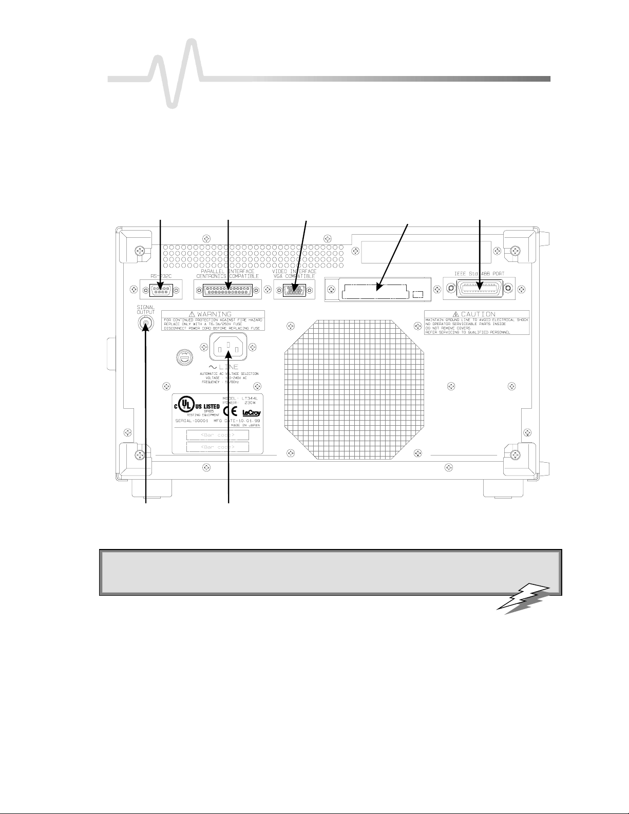
Yo ucan fu llycontrol yo u r Waverunne r oscilloscopere m ote lyby usingeither th eGPIB (Gene ral Purpose
Inte rfaceBus) port or the RS-232-C comm u n ica tion po rt on thescoperea r pan e l, show n be lo w. The only
actions for which you must usethe front panel controls are the pow e ring up of the scope and these tting of
remote addresses. Use L eCroy’s ScopeExplorer software as the ideal interface between scope and PC (see page
11).
RS-232-C Port
Centronics Port
PowerInputBN C SignalOutput
External Monitor Port
PC Card Slot
(Mem o ry/ Hard-Diskcard )
GPIB Port
Waverunner back panel, including the G PI B and R S - 2 32-C port s us ed in remote cont rol.
: U se Waverunner Remote Control Assistant to monitor all your remote control oper ations. See the
TTIIPP:
COMM_HELP
command in Part T wo of this manual, and Chapter 12 of the
Op e r ato r’s Man ual
,“Use
Waverunner with PC” .
LT3XX-RCM-E Rev B ISSUED: January2002 5
Page 4

P ART O NE: ABOUT REMOTE CONTROL
STANDARDS
*
LeCroy remote control commands conform to the GPIB IE EE 488.2
ex ten sionof the IEEE 488.1 stan d a rd, whichdeals ma inlywith ele ctrical andmecha n ical issue s . The IEEE
488.2 recommendations hav ealso bee nadop tedfor RS-232-C commun ica tionswhe re v e r approp ria te .
PROGRAM ME SSAGE S
Yo ucontrol the oscillosco pe re m ote lyusing program messa g es th a t consist of one or seve ra l comm a n d s or
qu e rie s . The progra m me ssa g es yo usend fromtheexternal controller to the W a v e runn e r oscilloscope must
conform to precise format structures. The oscilloscop e will execute all program messages se nt in the correct
form, but will igno re thosewith errors.
You can use uppe r- or lower-case cha racters, or both, in program messages.
W a rningor error messa g es are normallynot reported unless the controller explicitlyexam ines the relevant sta tus
register, or if the status-enable registers have been set so that the controller can be interrupted when an error
occurs . If you connect an external monitor to the Wa verunner’s RS-232-C port, howeve r,you will be ableto
observe all your remote control transactions, including error messages, as they happen. See the command
COMM_HELP in Part Tw o, “Commands.”
Program messages are separated by semicolons ; and end in a terminator:
<command/que ry>;.........;< comma nd/qu e ry> <terminator>.
Th eoscilloscop ewill not decodean incom ingprogram mes sa g ebefore receivin gits terminator. Theexce ption is
w h e ntheprogram mess a g eis longer tha n the 256 byte inpu t buffer; then the oscilloscopewill start an a ly zin gthe
message when the buffe r is full. Commands and queries are executed in the order in which they are transmitted.
standa rd. This may be conside red an
In GPIB mode ,thefollowing are validte rminators:
<NL > New -line character (i.e . the ASCII new-line character, whose decimal value is 10).
<NL >< EOI> New -line character with a simultaneous < EOI> signal.
<EOI>< E OI> Signa l together with the last character of the program message.
The<NL> < EOI> terminator is alw a ys use d in respo ns emessag es sent by the oscilloscop eto thecontro lle r.
In RS-232-C commun ica tions , you candefine the termin a tor with thecomma n dCOMM_RS232. The default
valueis <CR>, w hic h is theASCII carriage re turn charac ter, w h o sedecimal valueis 13.
NNOOTTEE:
: T he < E OI> signal is a dedicated GPIB interface line, which can
be set witha special call to the GPIB inter face dri v er. Referto theGPIB
in ter f ace manufacturer ’s manual andsuppo r t pr o gr am s.
*ANSI/IEEE Std. 488.2–1987, IEE E Stan da rdCodes, Formats, Protocols, and Common Commands. TheInstituteof Electrical and E lectronics Engine e rs
Inc., 345 East 47th Stree t, NewYork, NY 10017 USA.
6 ISSUED: January2002 LTXXX-RCM-E Rev B
Page 5

C HAPTER O NE:
COMMAN DSAN D QUE RIES
Program messages aremade up of one or more commands or queries. Whilethe command directs the
oscillosco p eto cha ng eits state (for example, its timebase or vertical sensitivity) th eque ry ask s the oscillosco p e
about that state. Very often, you will use the same mnemonic for a command and a query, the query being
identified by a ? afte r the last character.
For ex a mple, tochang ethetimebaseto 2 ms/div ,send this comman d to theoscilloscop e:
TIME_DIV 2 M
Or, to ask th eoscilloscop eabou t its timebas e ,send this qu e ry:
TIME_DIV?
A que ry cau ses the oscilloscopeto senda re s p on semessage. Thecontrol program should readthis me ssage with
a ‘read’ instructionto the GPIB or RS-232-C interface of thecontroller.
Theresponsemessagetotheabovequerymight be:
TIME_DIV 10 NS
The portion of the query preceding the question mark is repeated as part of the response message. If desired,
this text canbesuppressed with thecommandCOMM_HEADER.
Dep ending on thestate of the oscilloscope and the computation to be done, seve ral seconds may pass before a
response is received. Command interpretation does not have priority over othe r oscilloscope activities.
The general form of a command or a query consists of a command header, <header> , optionally followed by
one or several parameters, < data>, separated by commas:
Overview
<header>[?] <data>,...,<data>
The notation [?] shows that the question mark is optional (turning the command into a query).
There is a space between the header and the first parameter.
There are commas between parameters.
The following are examples of howprogram
messages are made up of commands and queries...
GRID DUAL: This program message consists of a
sing lecomman d that instructs theoscilloscop eto
display a dual grid.
Thetermin a tor is not shown, as it is usually automaticallyadde dby the interfa cedriver routine w riting to GPIB
or RS232.
DZOM ON; DISPLAY OFF; DATE?:This program message consists of tw o commands, follow ed by a
query . They instruct the oscilloscope to turn on the multi-zoom mode, turn off the display , and then ask for the
current date. Again, the terminator is not shown.
DATE 15,JAN,1993,13,21,16: This command instructs the oscilloscope to set its date and time to 15
JAN 1993, 13:21:16. Thecomma ndhead er DATE indicates the action, the 6 data values specify it in detail.
LT3XX-RCM-E Rev B ISSUED: January2002 7
: Set the controller I/ O timeout conditions
TTIIPP:
to th ree ormo re seco nds to give th escopetime
to respo n d. Anincorr ect query will no t get a
re sp o nse; and, if Remote Con tr o l Assistant is
ena bled, a beep wil l sound.
Page 6

P ART O NE: ABOUT REMOTE CONTROL
HEADERS
The hea der is the mnem on ic form of the ope ration to be performed by the oscilloscop e. Most comman dand
query headers havea long form, which allow s them to be rea d more easily, and a short form for better transfer
and decoding speed. The two are fully equivalent and you can use them interchangeably. For example,
TRIG_MODE AUTO and TRMD AUTO are two separate but equivalent commands for switching to the
automatic trigger mode.
Some comm a n dor que ry mne m on ics are impose d by th eIEEE 488.2 stan d a rd. Theyare standa rdize dso that
diffe ren t oscilloscope s w ill pres e nt the sameprogramminginte rface for similar functions. All these mnemon ics
beginwithanasterisk*. For example, the command *RST is the IEEE 488.2 impose d mnemon ic for resetting
the oscilloscope, whereas *TST? instru cts theoscilloscop eto pe rform an internal self-test and repo rt the
outcome .
HEADERPATHS
Ce rtain commands or queries apply to a sub-section of the oscilloscope; for example, a single input channel or a
trace on the display . In such cases, you must pre fix the header by a path name that indicates thechannel or trace
to which the command applies. The header path normally consists of a tw o-letter path name followed by a
colon : immediately prece ding the command header. One of the w ave form traces can usually be spe cified in the
header path:
HEADER PAT H N AM E WAV E FOR M TRACE
C1, C2
C3, C4
M1, M2, M3, M4
TA, TB, TC, TD
EX, EX10, EX5
LINE
Example: C1:OFST -300 MV Command to set the offset of Channel 1 to −300 mV.
You need only spe cify a header path once. Subsequ ent commands with header destinations not indicated are
assumed to refer to the last defined path. For example, the queries C2:VDIV?; C2:OFST? ask: What is the
vertical sensitivity and the offset of channel 2? While the queries C2:VDIV?; OFST? ask exactly the same
qu e stion w ithou t repe a ting the pa th.
Channe ls 1 and 2
Channe ls 3 and 4 (on four-channel models)
Memories 1, 2, and 3 and 4
Trac es A, B, C and D
External trigger
LINE sourcefor trigger
8 ISSUED: January2002 LTXXX-RCM-E Rev B
Page 7

C HAPTER O NE:
DATA
Whenever a command or query uses additional data values, thevalues are expresse d as ASCII chara cters. There
is a single exception: the transfer of wave forms with the command/query WAVEFORM, where the w ave form can
be expressed as a sequence of binary data values. See Chapter 4, “ Wavef or m St r uctur e.” ASCII data can
have the form of character, numeric, string, or block data.
CHARACTER DATA
Thesearesimplewordsor abbreviations to indicate a specificaction.
Example: DUAL_ZOOM ON
In this example, the data value ON commands the dual zoom mode to be turned on (the data value OFF will
havetheoppositeeffect).
However, this can become more complex. In some commands , where you can specify as many as a dozen
different para meters, or wherenot all theparameters areapplicableat thesametime, theformat requires pairs o f
data values. The first value names the paramete r to be modified, while the second gives its value. Only those
parameter pairs changed need to be indicated.
Example: HARDCOPY_SETUP DEV,EPSON,PORT,GPIB
In this example, two pairs of parameters have been used. The first specifies the device as an EPSON (or
compatible) printer, while the second indicates the GPIB port. While the command HARDCOPY_SETUP allows
many more parameters, eithe r they are not re levant for printers or they are left unchanged.
Overview
NUMERIC DATA
The numeric data typ e is used to enter quantitative information. Numbers can be entered as integers or
fractions, or in exponentialrepresentation:
TA:VPOS -5 Movethe disp laye d trace of Trace A dow nw ards by five divisions.
C2:OFST 3.56 Set the DC offset of Channel 2 to 3.56 V.
TDIV 5.0E-6 Adjust thetimebaseto5 µsec/div.
Example: There are many w ay s of setting the timebaseof theoscilloscopeto 5 µsec/ div:
TDIV 5E-6 Exponential notation, without any suffix.
TDIV 5 US Suffixmultiplier U for 1E−6,withthe(optional)suffixS for seconds.
or
TDIV 5000 NS
TDIV 5000E-3 US
Yo ucan follownu m e ric valu es with multiplie rs andunits, to modify the valu eof the numerica l ex p re ssio n.The
following mnemonics are recognize d:
LT3XX-RCM-E Rev B ISSUED: January2002 9
Page 8

P ART O NE: ABOUT REMOTE CONTROL
MULT IPLIER E XP.NOT E. SUFFIX MULT IPLIER E XP.NOT E. SUFFIX
EX 1E18 Exa - PE 1E15 PetaT 1E12 Tera- G 1E9 GigaMA 1E6 Mega- K 1E3 kiloM
N
F
STRING DATA
Thisdata type enables you to transfer a (long)string of charactersasa singleparameter. Simplyencloseany
sequence of ASCII characters betwee n single or double quotation marks:
MESSAGE ‘Connect probe to point J3’
The oscilloscope displa ys this messagein the Message field above the grid.
BLOCK DATA
These are binary data values coded in hexadecimal ASCII: four-bit nibble s translated into the digits 0 through 9
or A through F, and transmitte d as ASCII characters. They areused only for the transfer of w ave forms from
Wa verunner to controlle r (WAVEFORM) and for Wave runner panel se tups (PANEL_SETUP)
RESPONSE MESSAGES
The oscilloscope sends a response message to the controller in answer to a query. The format of such me ssages
is thesameas that of program messages: individual responses in the format of commands, separated by
semicolon s ; and ending in terminators. These messages can be sent back to the oscilloscope in the form in
which they were received, to be accepted as valid commands. In GPIB response messages, the < NL > <E OI>
terminator is alw ays used.
1E−3
1E−9
1E−15
milli- U
nano- PI
femto- A
1E−6
1E−12
1E−18
micropicoatto-
Example: The controller sends the program message:
TIME_DIV?;TRIG_MODE NORM;C1:COUPLING? (terminator not shown).
The oscilloscope might respond to this with:
TIME_DIV 50 NS;C1:COUPLING D50 (te rminator not show n).
The response message re fers only to the queries: TRIG_MODE is left out. If this respon seis sent bac kto the
oscillosco p e, it is a valid program me ssagefor setting its timeba seto 50 ns/div and the inpu t coup lingof
Channe l 1 to 50 Ω.
Whenever you expect a response from the oscilloscop e, you must have the control program instruct the GPIB
or RS-232-C inte rface to readfrom th eoscilloscop e. If thecontroller sen d s ano the r program me ssa g ewithou t
reading the re sponse to the previous one, the response message in the output buffer of the oscilloscope will be
10 ISSUED:January 2002 LTXXX-RCM-E Rev B
Page 9

C HAPTER O NE:
disca rde d . The oscilloscop eke e p s to stricter rule s for respon semessa g es than for accep tan ceof program
messages. While you can send program messages from the controller in uppe r- or lower-case characters,
response messages are always returned in upper-case . Program messages may contain extraneous spaces or tabs
(white space), but response messages will not. And while program messages may contain a mixture of short and
long command or query headers, response messages alway s use short heade rs by default.
However, you can use the command COMM_HEADER to forceth eoscilloscop eto uselong headers, or none at
all. If the response header is omitte d, the response transfer time will be minimized. But the response w ill not be
ableto be sent bac k to the oscillo scope. Suffix units are also suppresse d in there spon se .
If you were to set the trigger slope of Channel 1 to negative, the query C1:TRSL? might yieldthefollo wing
response s:
Overview
C1:TRIG_SLOPE NEG header format: long
C1:TRSL NEG header format: short
NEG
header format: off
: Wav efo rm s yo u obtain fromthe
TTIIPP:
oscilloscope using the query
WAVEFORM?
a special kind of response message. Control
theirexact format by using the
COMM_FORMAT
an d
COMM_ORDER
are
commands.
USE SCOPEEXPLORER
Scop eExplorer is an easy-to-use and pra ctical softw a re tool for interfacing your Wa verunner oscilloscope with a
PC running Window s:
1. Connect the scopeto a PC usingeither theGPIB (you’ll need a PC with GPIB card installed) or PCstandard RS-232-C po rt on th escope ’ sre a r pa n e l.
2. DownloadScopeExplorer freeof chargeat http:/ / www.lecroy .com/scopeexplorer. Or inquire at your
LeCro ycustomer service center.
3. Having installed ScopeExplorer, open it as you would any Windows program. Use its on-line help to do the
follow in g :
Use the teletyp e-like terminal to send standard remote control commands from computer to
oscillosco p e, andto display theWa v erunne r respon seon th ePC.
Control the scope by means of an interactive, virtual scope front panel.
Pipese que nces of commands from a file to the scope, then send thescope’ s responses to another file.
Transfer pixel-for-pixel copies of your W ave runne r display to PC, then viewthem, print them, or both
from the computer. With a single press of a button or key , you can copybitmap wa veform images to
the Windows Clipboard, re ady to paste into any Window s application.
Cap tureWaverunner front panel setups and, using a long file name , store the m on the computer. You
can then transfer them back into the scop e to reproduce an identical setup .
Transfer your waveforms to PC, and store them in either the compact L eCroy Binary format, or an
ASCII version compatible with PC-based analysis products.
LT3XX-RCM-E Rev B ISSUED: January2002 11
 Loading...