

Page 1
Kop
Platte tekst
Windows
Version
Full manual available in
EN / NL / DE / FR
from creatrhs.lpfrg.com
Page 2

facebook.com/lpfrg
twitter.com/Leapfrog_3D
instagram.com/leapfrog_3d
Sign up for our newsletter www.lpfrg.com
Follow us online!
Page 3

1
Dear Customer,
Congratulations with your very own Leapfrog
Creatr HS! In this document we will help you
get started with your rst print and with all the
prints to come after that. Also, we would like to
help you get acquainted with the Leapfrog 3D
Printers Ecosystem. We will be by your side
when you are setting up your printer and help
you with any questions you might have during
printing. We will also cheer you on when you
are making your amazing and value-added
prints.
The Ecosystem: tips and tricks, installation
video’s, and support
You are now ofcially part of The Ecosystem: the place where all Leapfrog 3D printer users gather
to help each other and to interact with the Leapfrog 3D Printers support team. Here are a few valu-
able tips on what you are able to nd there.
The Ecosystem can be entered through creatrhs.lpfrg.com. The Ecosystem is constantly growing in
content and users. Here are some of the most important things you can nd:
• Installation and support videos, as well as the manual for all the printers
• The latest software settings for all materials (posted under “knowledgebase”)
• Solutions for the most common issues
• Our forum, where users help each other and where you can post your amazing prints (every
once in a while, we will highlight a few in our newsletter and on our website, we will always
mention you of course!)
• The Leapfrog 3D Printers support team: if you have any questions you can just submit a ticket
online (“request help”) and we will get you on your way.
Are you all set to start?
To get started you need the following items:
• Your Creatr HS
• At least one lament
• Print stickers
• Your Materialise Creatr license key that you received with the Leapfrog 3D Printer
•
We will keep you up to date on our social media platforms (left page) about print settings and other
Leapfrog 3D Printers news. You are also invited to share your prints on our pages.
Now let’s start,
Happy printing!
The Leapfrog team
The ecosystem
Page 4

Page 5

3
Table of content
1. Making your very rst 3D print – Quick Print Guide
1.1 Unpacking your Creatr HS and nding the right place for it 4
1.2 Getting to know your printer 5
1.3 Plugging in your Creatr HS 6
1.4 Preheating the printer 6
1.5 Loading lament 6
1.6 Checking and adjusting the bed 7
1.7 Printing 8
2. Preparing for your next print
2.1 Removing your print and replacing your print sticker 9
2.2 Changing lament 10
3. Creating your own printable le: from STL to gcode
3.1 The 3D printing workow – from idea to print 11
3.2 Installing Materialise Creatr 11
3.3 Materialise Creatr software overview 18
3.4 Materialise Creatr workow 19
3.5
Prole editor 25
3.6 Congure Printer 30
4. Frequently Asked Questions
4.1 How can I solve the issue of the print not sticking to the bed? 31
4.2 What should I do when I cannot get my lament to go through the lament
guiding tube? 32
4.3 What can I do if my lament does not come out of the extruder? 32
4.4 My print surface is very rough, how can I solve this? 32
4.5 Where do I go with my other questions? 32
5. Glossary of 3D printing vocabulary
5.1 3D printing vocabulary 34
5.2 Getting to know your printer 36
Page 6

Making your very rst 3D print – Quick Print Guide
4
1. Making your very rst 3D print
– Quick Print Guide
We know you cannot wait to start 3D printing! In this guide we will take you on the easiest journey
from box to print.
This section contains the following information:
1.1 Unpacking your Creatr HS and nding the right place for it
1.2 Getting to know your printer
1.3 Plugging in your Creatr HS
1.4 Preheating the printer
1.5 Loading lament
1.6 Checking and adjusting the bed
1.7 Printing
1.1. Unpacking your Creatr HS and nding the right place for it
Unpacking your Creatr HS carefully, according to the following steps, ensures that the machine
stays calibrated (although in some cases decalibration might occur during transport). These steps
you only have to follow when your brand new Creatr HS arrives at your doorstep for the rst time.
Before you start, make sure that you have cleared a spot where you want to place the printer. We
advise you to nd a place at room temperature, where there is no draft (for example next to a window) and where the printer cannot get wet. Choose a surface which is sturdy (so the printer cannot
move) and supports the weight of the machine. It is useful to have another set of hands to help out,
the machine is quite heavy.
STEP 1: Cut the tie cords and lift the top of the box from where the handles are.
STEP 1: Cut the tie cords and lift the top box.
Page 7
Making your very rst 3D print – Quick Print Guide
5
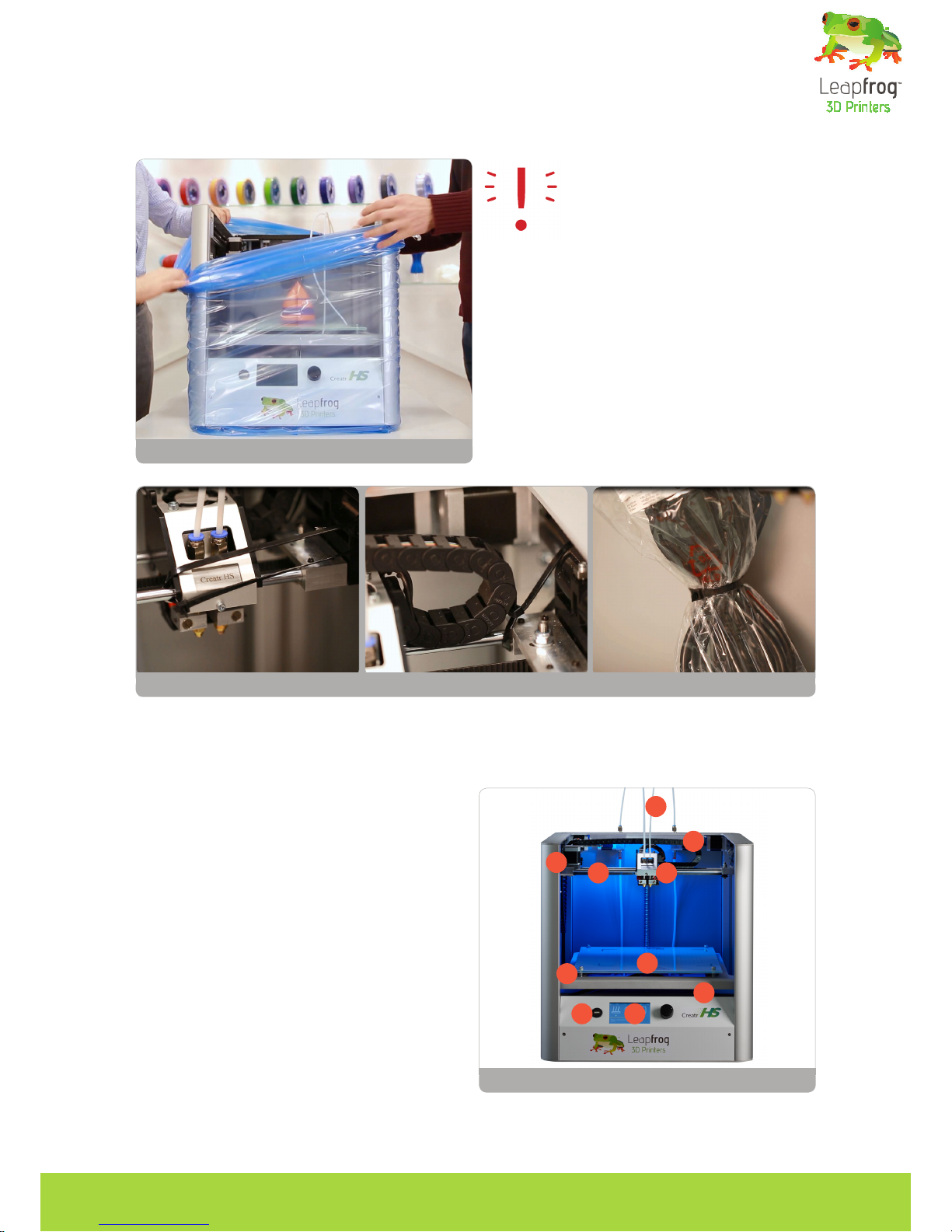
STEP 2: Pull off the tape from the plastic bag wrap on the top of the printer and push the plastic
down and away from the printer.
NOTE: Do not grab the Creatr HS by
the top cover as this can damage it.
Lift the machine from the bottom.
STEP 3: Place the printer in its new location and
make sure it sits rmly on all four rubber feet.
If necessary adjust their length by unscrewing
the feet slightly.
STEP 4: Remove three sets of tie-wraps with a
cutting tool: at the front of the carriage, in the
corner of the carriage and in the back of the
printer.
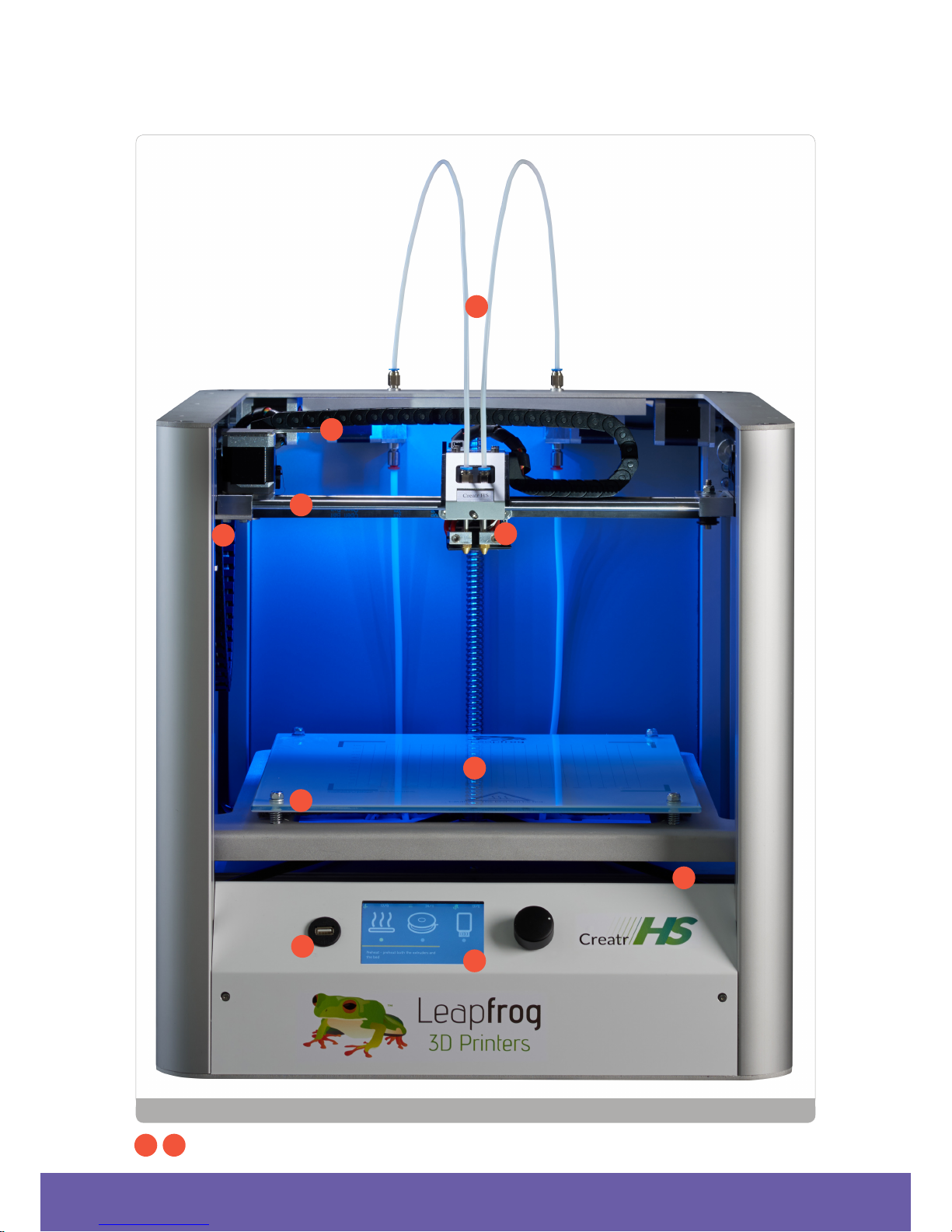
1.2 Getting to know your printer
1. Printing head and extruders
2. Filament guiding tube
3. Filament drive unit
4. Axes
5. Print bed
6. Print bed levelling knobs
7. Display
8. Quick release knob (back)
9. USB port for USB stick
10. USB port for connecting to the computer
(back)
11. Belt (inside the printer)
12. Z-sensor adjustment knob (only to be used
when bed levelling cannot be achieved using
the print bed knobs!)
Large image including close ups on page 36.
STEP 2: Remove plastic wrap
STEP 4: Cut the tie wraps at the front and back of the carriage and in the back of the printer
The Creatr HS
1
2
4
5
6
79
12
11
3
Page 8
Making your very rst 3D print – Quick Print Guide
6
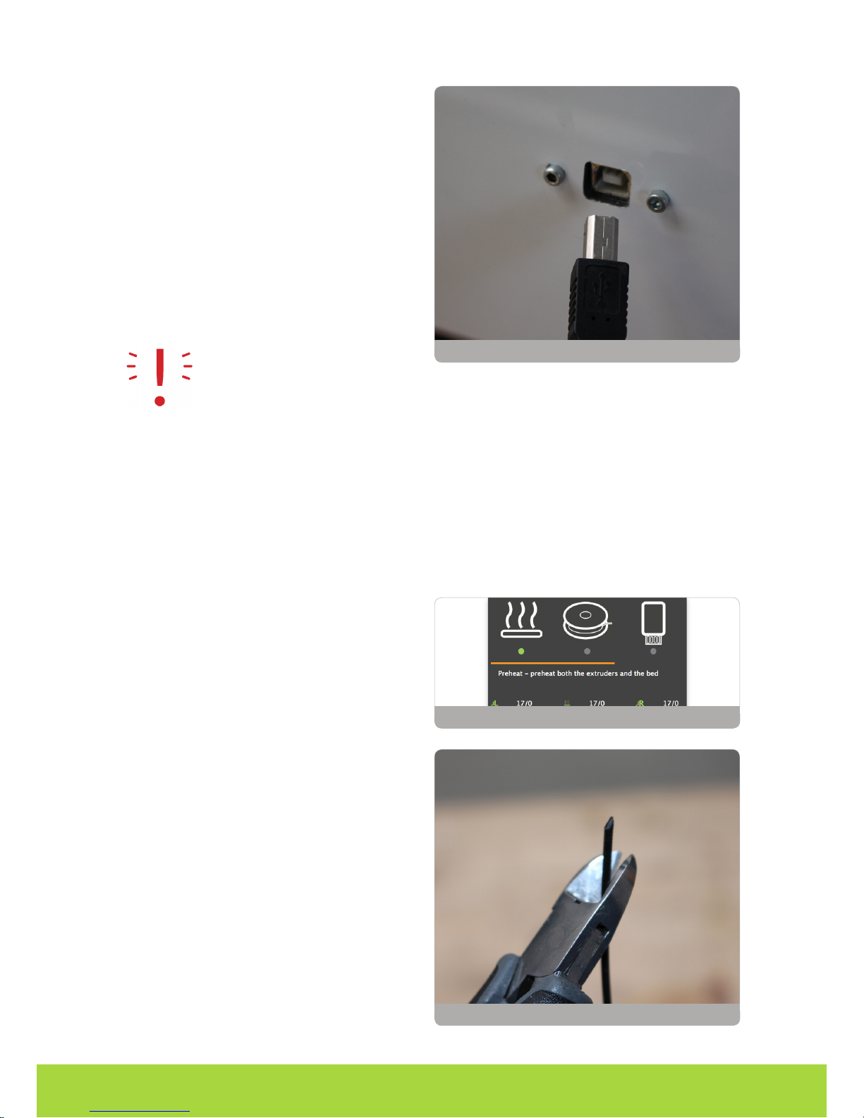
1.3 Plugging in your Creatr HS
OPTIONAL: If you want to use the printer connected to your computer, use the USB cable
supplied with the printer, insert the USB-A (at
rectangular connector) cable in your computer
and insert the USB-B (square connector) cable
in the backside of the Creatr HS.
In this Quick Guide we will use the stand-alone
modus, therefore the cable does not have to be
plugged in.
NOTE: If your printer has a USB-A
(at rectangular) backside connection, make sure you only use the USB-A cable with the built in FTDI chip that is included
in the box. Any other USB might interfere with the communication.
STEP 5: Plug the power cord in the outlet and turn on your Creatr HS.
1.4. Preheating the printer
Before you start loading your lament, it is necessary to preheat your printer. Heating your extruders will make sure that your lament will melt and feed through. You are also preheating your print
bed. This will make sure your print will stick to your bed.
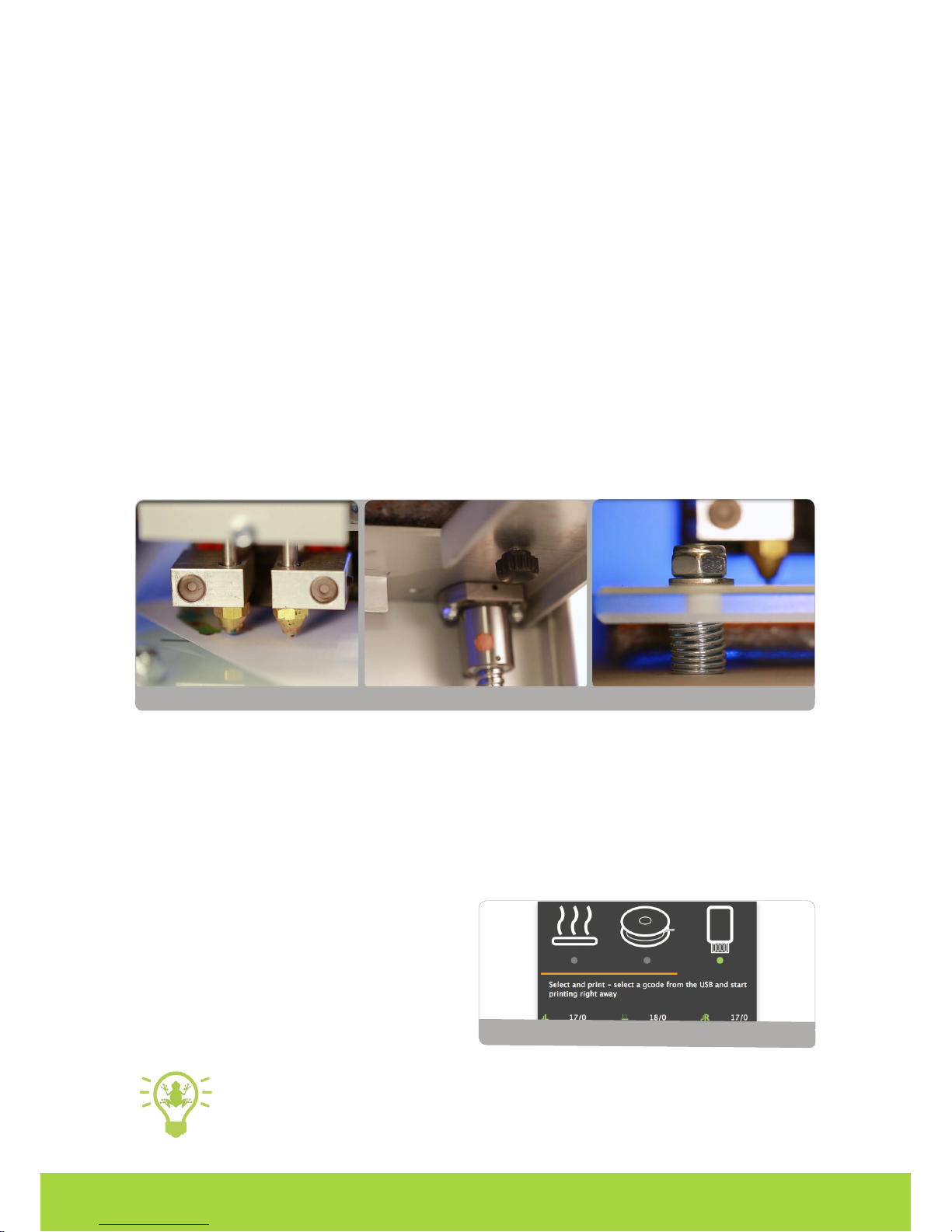
STEP 6: To preheat, scroll to the preheat icon
on your screen, and push the button. If the colour of the icon changes, your nozzles and bed
are preheating.
1.5. Loading lament
The Creatr HS is compatible with a wide range
of 1.75 mm laments. All laments provided by
Leapfrog 3D Printers are of high quality and are
thoroughly tested by us. For every lament, we
also provide standard settings for Simplify3d
(to be found in The Ecosystem).
STEP 7: Unpack your role of lament and cut
the end into a sharp point.
OPTIONAL: connect USB cable to port
STEP 6: Preheat
STEP 7: Cut to a sharp point
Page 9
Making your very rst 3D print – Quick Print Guide
7
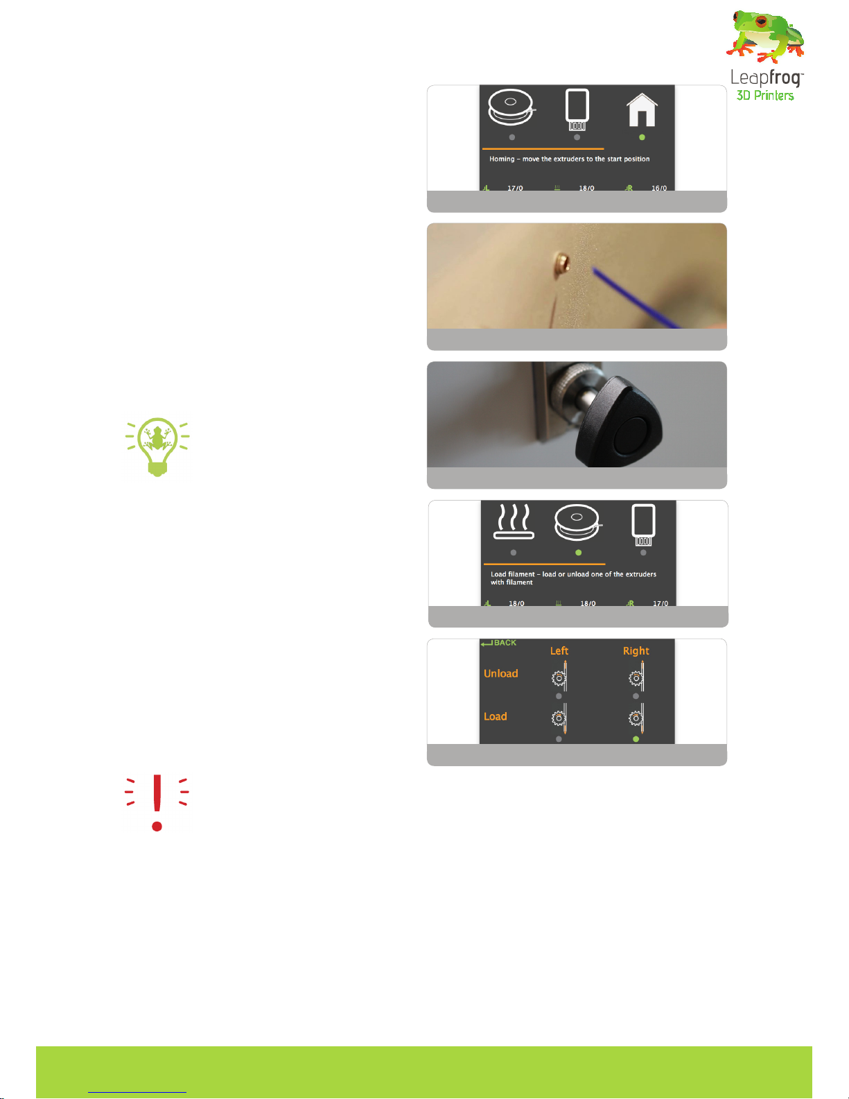
STEP 8: Home the printer so you can reach
the bottom where the lament has to be fed
through. To do this, select the home icon on
your screen and press the button to start homing.
STEP 9: Make sure your nozzles are preheated
to at least 180 degrees Celsius. Place your role
of lament in the bottom of the printer. Start
feeding the lament through the hole.
STEP 10: Once you reach the lament drive
unit, pull out the quick release knob on the
back, and feed the lament through further
until they reach the printer head.
TIP: If you have problems with
feeding your lament, there is a
possibility that your lament has
trouble to pass the lament guiding
tubes connection. Take the top connections out
by turning them counter-clockwise. Manually
feed some lament while pulling the quick release knob, and put the connections back. Put
the lament guiding tubes back in place.
STEP 11: On your screen, select the lament
icon and push the button.
STEP 12: Select your extruder and press “Load”.
After a few seconds, lament should be owing
out of the extruder. Remove the printed lament once the extrusion is nished.
NOTE: Do not touch the bed or the tip of the extruder with your ngers, this is very hot.
STEP 13: To go back to the main menu turn the button counter-clockwise.
1.6. Checking and adjusting the bed
Each Creatr HS is carefully calibrated before it leaves Leapfrog 3D Printers’ headquarters. However, during transport, calibration might get shifted. Calibration means that your extruder is at the
correct distance from the bed to print smoothly, and that your bed is exactly levelled. Here is explained how you can slightly adjust the calibration during printing. If a full recalibration is necessary, the steps described in Chapter 3.9 should be followed.
STEP 8: Home the printer
STEP 10: Pull the quick release knob
STEP 9: Feed lament in hole
STEP 11: Select lament icon
STEP 12: Extruder ‘load’
Page 10
Preparing for your next printMaking your very rst 3D print – Quick Print Guide
8
In the next paragraph you are going to start printing. During this print you can manually adjust the
bed while printing. Check if the bed is levelled during the rst 2 or 3 layers of the print and verify if
the lament is adhering well to the bed.
• If a corner of the bed is too far from the nozzle you observe lament being extruded too loosely
in this area of the print bed, causing your print not to stick.
• If a corner of the bed is too close to the nozzle the extruder scratches through the print sticker,
or (almost) no lament comes out of the nozzle.
You can manually adjust the four corners of the bed where necessary during printing by very care-
fully turning the bed levelling knobs. Only turn it slightly! Usually not more than a quarter of a turn
is necessary. Looking from the top, slightly turn the knob clockwise in the corner where no lament
is owing or where the nozzle is scratching the print sticker. Turn the knob counter-clockwise in the
corner where the lament is not pressed enough onto the bed and comes loose easily.
If these steps are not sufcient to successfully calibrate the printer, it can be recalibrated using the
computer, which is explained in Section 3.
1.7 Printing
STEP 14: Surf to creatrhs.lpfrg.com and click on ‘Demo Print Downloads’. Select the single extruder print.
STEP 15: Insert your USB stick in the front USB port of your printer.
STEP 16: On your screen, select the USB stick icon and press the button.
STEP 17: Find your le, select it and press the
button. It can take a few seconds for the les to
be displayed if there are many les on the USB
stick. The printer will now start to heat up to
the required heat encrypted in the le. Once it
hits that temperature, it will start printing!
TIP: The rst layers of a print are always the most difcult and it is best to carefully observe them. Slight adjustments to the level of the bed during the rst print layers might
be necessary to obtain a successful print.
Calibrating the printer.
STEP 17: USB port and display in one screen
Page 11

Preparing for your next print
9
2. Preparing for your next print
In this chapter we will take you through the processes of preparing your printer for your next print.
We will take you through the processes of replacing your print sticker, exchanging your lament
and we will offer you to methods of calibrating your machine: manually and through using Simpli-
fy3d.
2.1. Removing your print and replacing your print sticker
2.2. Changing lament
2.1 Removing your print and replacing your print sticker
The print bed of the Creatr HS is made out of glass to ensure that it is as at as possible. However,
it is sometimes difcult to keep your print stuck to it. To make sure that your print sticks to the bed,
you need to apply a print sticker. You can re-use your sticker for prints over and over again as long
as it is not damaged. Even when it is damaged, you could opt to place your print on another section
of the bed where the sticker is not damaged yet (in order to learn how to do this, revert to Chapter
4 where we cover the Materialise Creatr software).
TIP: Removing your print from the bed: You can use a putty knife to make it easier to
remove your printed object. If the print still sticks on the print bed, heating up the print
bed to 40 degrees Celsius (see quick start) can make it easier to remove prints.
STEP 1: Check whether your print sticker is damaged or not. If it is damaged in one place, you may
also position your print on a different, undamaged area of the bed (you can do this while slicing your
print in Simplify3d).
STEP 2: If the print sticker is damaged and you cannot position your print on an undamaged spot,
remove the sticker by lifting one of the corners of the sticker and pealing it off. If you remove it too
quickly, the sticker is more likely to tear.
STEP 3: Remove the sticker glue by applying sticker remover or glass cleaner on the print bed. Be
sure to remove the whole sticker and all of the sticker glue so you will end up with a clean glass
plate. If residue is left behind, this could affect your print quality.
TIP: Use some abrasive soap with your putty knife on a cold (non-heated) print bed.
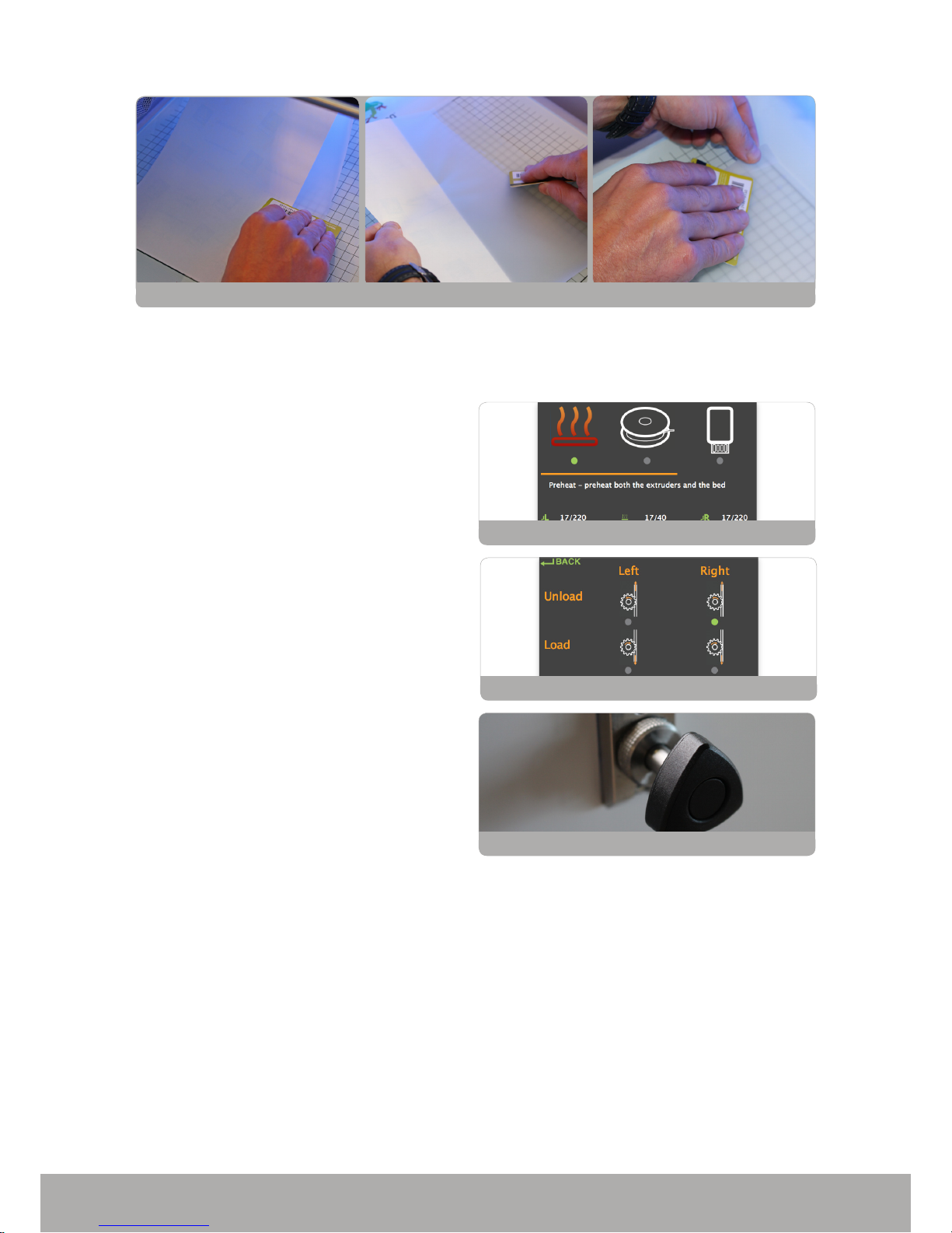
STEP 4: Apply the new sticker by placing the sticker on your print bed. If you are satised with the
position, take of the small part of the sticker. Use a plastic card to apply the sticker, work from the
inside to the outside and avoid air bubbles. Take off the big part slowly and use a plastic card to apply the sticker, work from the inside to the outside.
Page 12
Preparing for your next print
10
2.2 Changing lament
If you are ready to use a different role of lament for your next print, follow these steps to remove
your current role of lament.
STEP 1: Preheat your printer by selecting the
preheat icon in your screen and pushing the
button. Make sure the nozzle which contains
the lament you are about to exchange heats
up to at least 180 degrees Celsius.
STEP 2: Select the lament icon in your screen
and enter this menu by pushing the button. Select the extruder from which you want to re-
move the lament and select ‘unload’. The drive
unit will retract the lament.
STEP 3: Pull the quick release knob on the back
and pull the lament out all the way from the
feeding hole on the bottom. Make sure you roll
up your role of lament carefully and that the
end cannot get loose. Tangled lament can af-
fect the print the next time you use it.
STEP 1: Preheat your printer
STEP 2: Select ‘unload’
STEP 3: Pull the quick release knob.
STEP 4: Apply the new sticker
Page 13

Creating your own printable le: from STL to gcode
11
3. Creating your own printable le:
from STL to gcode
In this chapter we will teach you how to ‘slice’ (create your own 3D printable le name ‘gcode’) using your 3D part (or ‘stl’) as input. The slicing software we will be using to do so is Materialise Creatr
In the gcode, all movements of your printer and characteristics of the different layers are encrypted. With Materialise Creatr, you have the possibility to print with either standard print settings
that we prefabricated for you, or (as you get more advanced) you can tweak your own settings for
your print.
Among the many options that Materialise offers, there are options to change the temperature, the
layer height, the inll (how massive or how hollow you want your object to be), as well as options
for support structures (for structures with an overhang of more than 45 degrees). In Section 4.6.
we will go over the most important options. If you want more information on advanced printing
options, or support for your software, please revert to full Materialise Creatr manual
We will go over the following:
3.1 The 3D printing workow – from idea to print
3.2 Installing Materialise Creatr
3.3 Materialise Creatr software overview
3.4 Materialise Creatr workow
3.5
Prole Editor
3.6 Congure Printer
3.1 The 3D printing workow – from idea to print
Below is a schematic workow on how you get from an idea to a print. In this chapter, we will take
you through the last four steps: from STL to print.
3.2 Installing Materialise Creatr
The preferred software for your Leapfrog 3D printer is Materialise Creatr. This software package
prepares your 3D part into machine instructions for your 3D printer. Materialise Creatr is not sold
separately but bundled together with your 3D-Printer. So together with your 3D-Printer, you also
received a voucher code. You should use this voucher code to register the software.
Page 14

Creating your own printable le: from STL to gcode
12
Installation of the software
• Download the latest installer of the Creatr software on the Leapfrog website:
http://support.lpfrg.com/support/home
• Run the installer
• Now the software is successfully installed so you can press the Finish button
• Select the printer you want to use with the software and press the Add button
• The software is now completely installed and just need to be activated
Page 15

Creating your own printable le: from STL to gcode
13
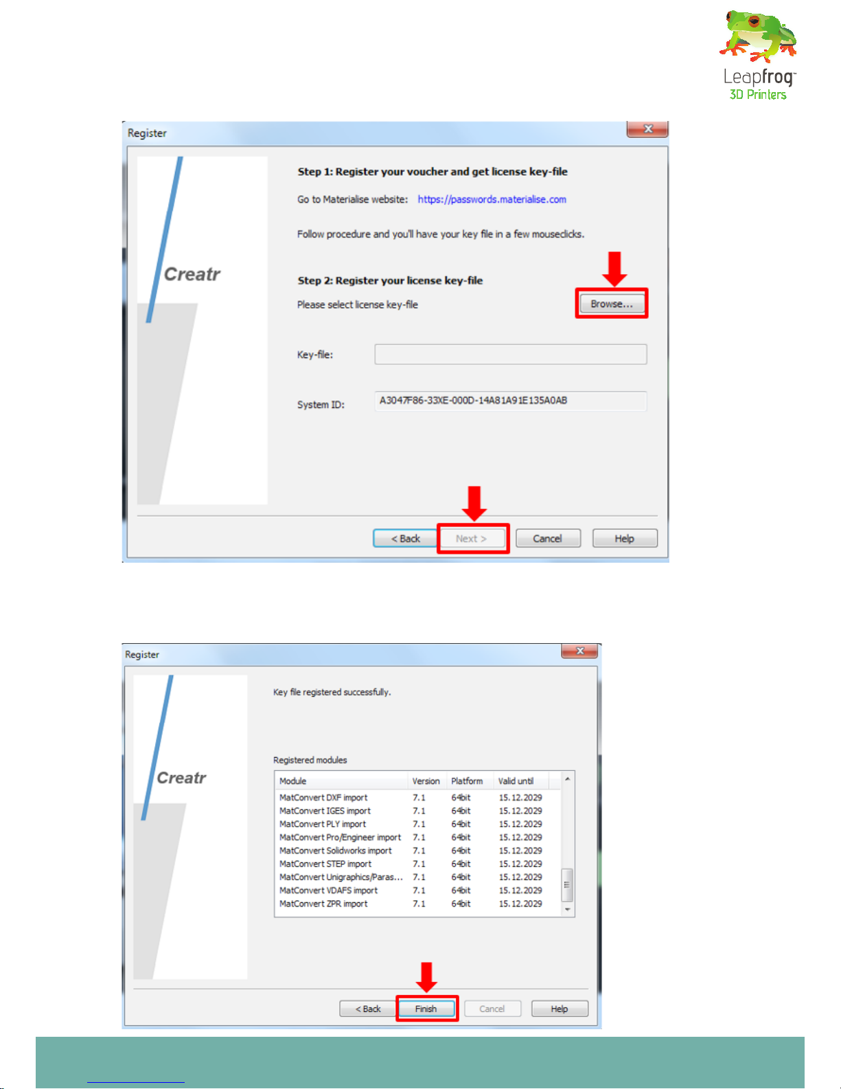
Registration of the software
• Open the Registration Wizard in the Creatr software by pushing the tool icon. When
installing the software for the rst time this will happen automatically when you start the
Creatr software.
•Select the License Option and click next
TIP: For more detailed info, please revert to the Materialise Creatr Manual via
http://support.lpfrg.com/support/home
Page 16

Creating your own printable le: from STL to gcode
14
• Copy the system ID from the registration wizard and go to the Materialise password
website by clicking the link. Make sure you have your voucher code ready.
• In the licensed software solutions section ll in your voucher code you received from
Leapfrog and press the submit button.
Page 17

Creating your own printable le: from STL to gcode
15
• Fill in your system ID from your computer that is provided by the registration wizard
into system ID eld on the password website and your email address and press the next
button.
Page 18

Creating your own printable le: from STL to gcode
16
• Check the registration details and press the request password button
• Save the license key on your computer by clicking the download button
Page 19
Creating your own printable le: from STL to gcode
17
• Browse for the license key you stored on your computer in the previous step and press
the next button
• Your license key is registered successfully and your software is ready to use. Press nish
button the exit the registration wizard. Enjoy the software
Page 20

Creating your own printable le: from STL to gcode
18
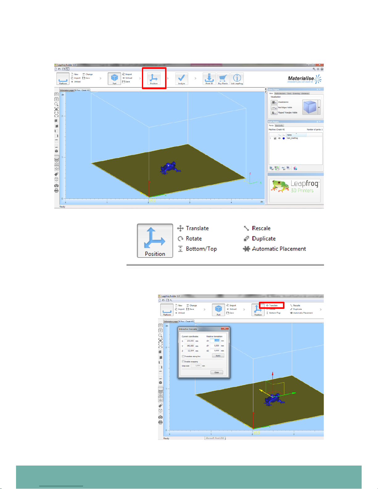
3.3 Creatr software overview
When you launch Creatr, you will arrive on the Information Page. To start working:
1. Click the Platform ow button and select New to choose your 3D-Printer
2. Click the Part ow button and choose Import to load your STL-le
3. Click the Position ow button if you want to translate, rotate, rescale or duplicate your
part(s)
4. Click the Analyze button to check if your loaded parts are buildable or not
5. Click the Build Processor button if you want to build your part(s) on your 3D-Printer
A. Use the functions on the View toolbar to visualize & inspect your STL-les
B. You can nd more advanced visualization & communication options on the Tool sheets
So be ready to ‘Go with the Flow’:
Page 21

Creating your own printable le: from STL to gcode
19
3.4 Materialise Creatr Workow
Platform
To start working in Creatr, you should
create a Platform or load an existing one.
Once you have a Platform, you can start
importing parts
• New empty platform
• Import existing le
• Unload platform contents
• Save platform
Import platform
Leapfrog Builder File
(.LBF)
Import part
Creatr is based on the STL-le format
which is the 3D-Printing Industry’s stan-
dard data format. An STL le is a triangular representation of a 3D object.
• Import a part (.stl) to add a part to the
platform
• Parts can be added to the platform le
Page 22
Creating your own printable le: from STL to gcode
20
Position
Press Position to change the orientation, scale, and position of a part.
Positioning options:
• Translate
• Rotate
• Bottom/top
• Rescale
• Duplicate
• Automatic placement
Translate
The translate operation allows
you to interactively move a part
(or a group of selected parts) to
another position.
Grab an Axis or Cardinal Plane to
move the selected part(s) in one
or two dimensions while visualizing in 3D view.
You can change your selection
during operation, just switch
between parts (click another) or
drag a window to select multiple
parts at once.
Page 23
Creating your own printable le: from STL to gcode
21
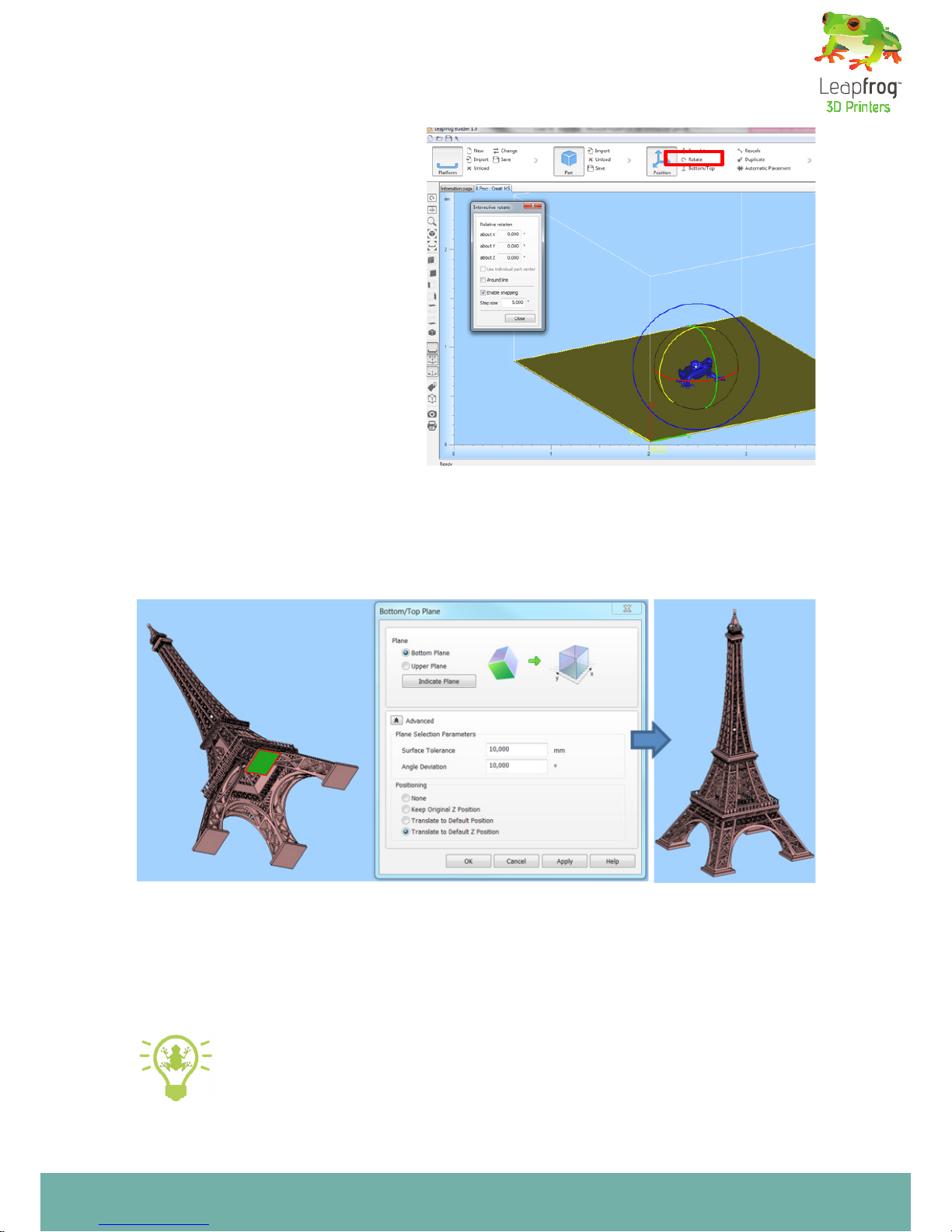
Rotate
As with Translate, grab one of the
circles to interactively rotate about
the chosen axis. Grab the blue circle
to rotate about an axis perpendicular
to the active viewpoint. You can also
change your part selection during
operation.
Use the Enable Snapping checkbox
to move parts in dened increments.
You can specify the step size yourself.
With the Interactive Rotate around
line, you can specify any line on any
part as rotation center
Bottom/Top
The Bottom/Top function allows easy orientation of the selected part by indicating a
plane as the bottom/top plane. This plane will automatically be oriented parallel to the
platform (i.e. the XY-plane).
Click the Indicate Plane button to select you reference plane (the selected plane is indicated in green). The selected plane will be orientated parallel to the platform facing the
upper or bottom (depending on your selection).
TIP: For full description of all the available positioning options, please revert to
the Materialise Creatr Manual
Page 24
Creating your own printable le: from STL to gcode
22
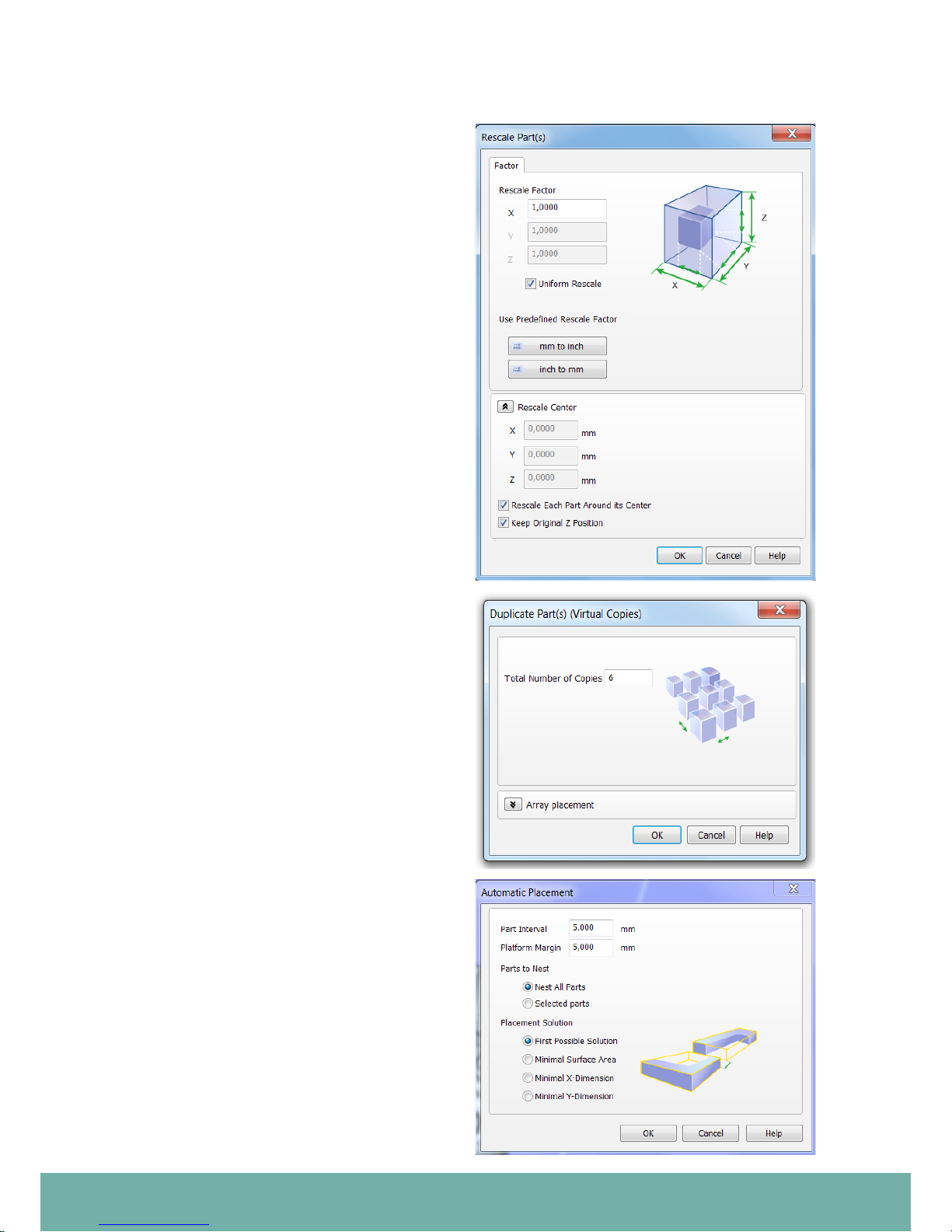
Rescale
The Rescale function gives you the ability to
change the dimensions of a part as a whole
or in only certain specied dimensions.
The Rescale Factor is a multiplying value for
the dimensions in that direction. When the
factor is 1, no rescaling is performed, when
the factor is 2, size is doubled. A factor larger
than 1 will enlarge the part, a factor smaller
than 1 will shrink the part.
Enable Uniform Rescale when you want
to use an identical factor in all directions.
Disable this option if you want to specify a
different value in X, Y and Z.
With the predened rescale factors you can
easily scale parts from mm to inches and
back.
Duplicate
This command automatically duplicates the
selected parts. The Total Number of Copies
you specify includes your original part.
You can also specify the Array Placement
of the copies i.e. the Number of Copies you
would like to have in the indicated directions
and the Spacing or distance between each
Copy.
Automatic Placement
This command will automatically place parts
on the build platform. Activating this function will open a dialog where the automatic
placement can be setup. The part interval
will dene the space between the parts
when placing the parts automatically. The
platform margin will indicate how far the
parts need to be placed from the borders of
the platform.
The parts to nest selection will give the user
the possibility to select all parts or just the
selected ones.
Page 25
Creating your own printable le: from STL to gcode
23
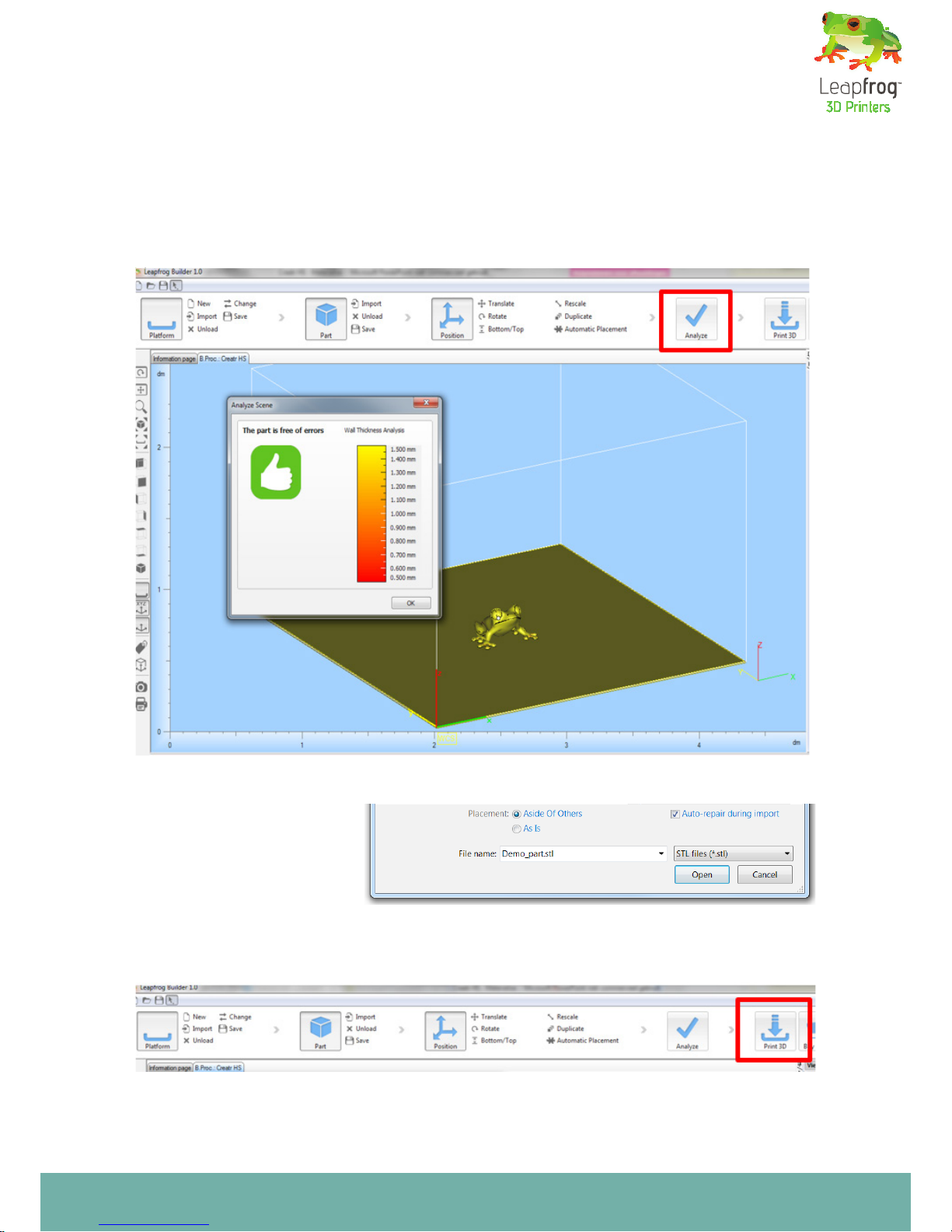
Analyze
The Analyze Scene function allows you to easily diagnose all parts on the active scene for
errors. This function will show a green thumb-up when all parts are ready to build and a
red thumb down when some of your parts contain errors and need xing . It will also give
the user information about the thickness of the walls in the parts on the build platform.
The information is given with color codes that indicate ticker of thinner walls by colors.
The meaning of the color is indicated in a graph in the analyze window.
During import, you have
the ability to perform an
Auto-Repair (enabled by
default).This algorithm will
automatically x some very
basic STL-errors (without
changing the geometry).
Print 3D
The models have now been correctly scaled and placed
Select Print 3D to prepare for the printing process
Page 26

Creating your own printable le: from STL to gcode
24
Submit a job
Select the Job Type
• 3D print (direct)
• Print to File (USB)
Provide a Job Name
Select Preferences to set the printer properties
Print settings of the platform
• How should the parts be printed?
• Layer height
• Build strategy (high speed, high accuracy)
• Support strategy (with support, brim, or
skirt)
Note: Original Manufacturer settings are denoted by OEM
Preferences
Once you click on Preferences the screen
on the right will open.
Here you have different options:
• Choose active nozzles
• Heated platform Bed on/off
• Material to print with (PLA, ABS, …)
Click on Edit Proles to edit and add new
printing settings.
Please revert to the next chapter for more
information on editing proles
Page 27

Creating your own printable le: from STL to gcode
25
3.5 Prole Editor
The prole editor allows the user to setup and manage the print and printer parameters.
These parameters are grouped into logical sections called proles. Each prole has a
parameter list attached to it that allow to make settings to the way the build processor
behaves.
Slicing
The slice prole section will allow the user
to edit, manage and dene the proles that
inuence the slicing behavior of the build
processor.
• Layer thickness: denes the thickness of
the slicing process in mm
• Border accuracy: denes the maximum de-
viation in mm a toolpath is allowed to have
towards the real toolpath.
TIP: For full description of all the
available options in the prole
editor, please revert to the
Materialise Creatr Manual
Page 28

Creating your own printable le: from STL to gcode
26
Material
The material prole section will allow the user to edit, manage and dene the proles that
dene a material lament used for building a part.
• Extrusion temperature: here the user can set the temperature the nozzle needs to have
to process the lament
• Bed temperature: here the user can set the temperature of the bed necessary to pro-
cess the lament
• Diameter lament: here the user can set the diameter of the lament.
• Print speed: here the user can set the nominal speed at which the lament will print.
• Material density: here the user can set the density of the lament in order to calculate
the consumed material during a print
In the section below we will discuss the materials that Leapfrog 3D Printers offer and give you a
general idea on how to use them.
Material Description
PLA Poly(lactic acid) or polylactide (PLA) is a thermoplastic aliphatic polyester
derived from renewable sources, such as corn starch, tapioca products
or sugarcanes. After printing, the surface is instantly smooth. There are
no toxic fumes coming heated PLA, so printing with this lament is safe
(although it is always advisable to print in a ventilated area).
PLA PRO PLA PRO is a PLA variety which provides more intense colouring as well
as UV-, draught- and heat resistance. This makes it very suitable for architects and industrial designers.
ABS Acrylonitrile butadiene styrene (ABS) is a common thermoplastic. This
is the same material as LEGO bricks are made of. After printing you can
smooth the surface of ABS using sand paper or acetone. ABS is commonly
used in engineering applications, since it can handle much more stress
than PLA. When printing with ABS, a very small amount of toxic fumes
may get into the air. It is advisable to print in a ventilated environment or
with a (fume) cover.
PVA Polyvinyl alcohol (PVOH, PVA, or PVAl) is a water-soluble synthetic poly-
mer. It is used as a support material for PLA in 3D printing because it can
be easily removed.
HIPS High Impact Polystyrene (HIPS) is used as a support material for ABS in
3D printing. HIPS can be solved using D-Limonene
Page 29

Creating your own printable le: from STL to gcode
27
Hybrid ‘Hybrid’ is high in strength and toughness, extremely suitable for printing
moving parts since it has an improved temperature resistance. This also
means Hybrid has to be printed on a higher temperature to reach the
right viscosity. It is a high strength engineering plastic which is also food
safe (FDA approved). There are no toxic fumes vaporizing when printing
with hybrid.
Nylon Nylon is a generic designation for a family of synthetic polymers known
generically as aliphatic polyamides. Nylon is one of the most commonly
used polymers. It has self-lubricating properties which can be useful in
for example bearings. The material is very tough and light. It is also able to
withstand higher stress than most other printable plastics making it more
suitable for engineering applications.
Build strategy
In the build strategy you can adjust the following parameters:
• Number of contours: here the user can set the number of contours that will be used to
build up the model.
• Up skin/ Down skin
• Pattern: here the user can set the pattern that will be used for processing the inll area.
There are 4 different patterns that can be used for inll:
• Raft: here the user can activate the generation of a raft structure.
• Skirt: here the user can activate the generation of a
skirt for priming the nozzles.
• Base layer:here the user can set the layer thickness
of the base layer.
Page 30

Creating your own printable le: from STL to gcode
28
Support Strategy
Support material is added during the printing
process in order to support the overhanging
parts of your design. Both the objects in the
image are not printable without support (as
some of the angles are more than 45 degrees).
If you would print these designs without sup-
port material, the print material would just
fall on the bed. You can build two types of support structures; breakaway support and soluble support.
Breakaway support is a support type that
adds support material in the same material
and color as the material you use to print your object. In this image the support material is printed
with the second extruder. After the print is nished you have to breakaway the support structure
manually. Using breakaway support simplies the slicing and printing process, however, it is not
suitable when the support is in places you can not reach. It will be difcult to remove if your print
is small.
Soluble support is only possible if you have two extruders (with your Creatr HS you are the lucky
owner of a dual extrusion 3D printer). The advantage of soluble support is that you can dissolve
your support structure after printing, and it hardly leaves any marks on the surface of your print.
At this moment, we support two types of support material:
• PVA, to be used to support a PLA print. PVA is solvable in ordinary tab water. The soluble sup-
port material needs to be inserted in the second extruder. PVA is the safest material to dissolve
since you only need water.
• HIPS, to be used to support an ABS print. HIPS can be solved using D-Limonene.
TIP: If you take care of a few things before or after using PVA or HIPS, you will ensure
the highest quality of your prints. Before using PVA or HIPS to print, make sure you ex-
trude the PVA or HIPS generously to ush away any remaining material in the nozzle.
TIP: After using PVA or HIPS, make sure you unload the lament after the print. Also,
clean out the nozzle thoroughly by loading another material (PLA or ABS for example)
through the nozzle and having it extrude. This will minimize the amount of residue left
over in your nozzle.
After your Creatr HS is nished printing, you need to remove your print [including the support material] from the bed. Place your object together with the support material in the correct solvent for
your support material and the support structures will dissolve. You do need some patience for this,
as it might take up to a few hours to dissolve.
NOTE: we sometimes get feedback from clients that want to speed up the dissolving of
PVA by using hotter water. Hot water might damage your print.
Structure with support overhang
Page 31

Creating your own printable le: from STL to gcode
29
• XY extension: here the user can set the off-
set in X & Y that will be used to generate the
support structure. The support structure will
be extended in X&Y
• Distance to part: here the user can set the
distance the support structure needs to keep
from the part(s) during generation of the
support structure.
• Self-supporting angle: here the user can set
the self-supporting angle that will be used to
determine which parts of a model need support and which not during the support generation. All areas that have a support angle
lower than the self-supporting angle will be
supported.
TIP: For full description of all the
available support options, please
refer to the Materialise Creatr
Manual.
Support options
• Enabled: here the user can activate the support generation function
• Add border: here the user can activate the generation of a border around the support structure.
• Z-offset: here the user can set an additional offset on the layer height used to print the support
structure.
• Line angle: here the user can set the angle that will be used to draw the support structure lines.
• Line distance: here the user can set the distance between 2 lines of the support structure pattern
Page 32

Creating your own printable le: from STL to gcode
30
3.6 Congure Printer
• Status: here the user can see what the status is off the communication with the machine
• Part: here the user can set which communication port on the PC will be used for com
munication with the printer.
• Reconnect: here the user can initiate a connection with the printer
• Emergency stop: here the user can execute an emergency stop of the printer when the
printer is connected over the communication port.
Page 33

Creating your own printable le: from STL to gcode
31
On the preference tab in the congure printer window the user can setup less frequently
changing settings of the printer conguration like:
• Nozzle usage: here the user can select which nozzle will be used on the printer.
• Material loaded on a nozzle: here the user can set the material linked to the nozzle.
• Processing temperature override: here the user can override the material temperature
that will be used for processing of the material
• Print mode: here the user can set which print mode will be used. The user can make a
selection between:
• Part-Part
• Part-support & Support-Part
• Inll-contour & Contour-Inll
Maintenance
Via the maintenance tab the user can make
a selection between several maintenance
functions like:
• Change lament: here the user can ac-
tivate a function to load a lament on an
extruder and a function to unload a lament
on an extruder.
• Calibrate heads: here the user can acti-
vate a function to calibrate the rmware for
dual nozzle printing.
• Calibrate platform: here the user can
activate a function to aid in adjusting the
leveling screws of the platform.
Manual control
Here the user gets information about the
most important values on the printer like
nozzle temperature and nozzle position and
can control all main functions of the printer
manually.
Note: The use of the manual functions is only possible when the
software is connected with the
printer through the communica
tion control. When no connection
is available all controls will be
grayed out.
Page 34

Frequently Asked Questions
32
Frequently Asked Questions
32
4. Frequently Asked Questions
Although our instructions in this manual are of course highly brilliant ;-) we can imagine that you
run into some questions while you are printing. This section of the manual is devoted to that. Note
that you can nd much more help and support in The Ecosystem, which you can access through
creatrhs.lpfrg.com/.
This section contains the answers to the following frequently asked questions.
4.1 How can I solve the issue of the print not sticking to the bed?
4.2 What should I do when I cannot get my lament to go through the lament guiding tube?
4.3 What can I do if my lament does not come out of the extruder?
4.4 My print surface is very rough, how can I solve this?
4.5 Where do I go with my other questions?
4.1 How can I solve the issue of the print not sticking to the bed?
If your prints do not stick to the printing glass there are several steps you have to check on:
• The distance between the extruder and the printing bed: If the distance is too big the layers will
not stick and when the distance is too small the extruder will scratch the previous layer causing
it to come off.
• The temperature of the bed and the nozzle: Make sure they are at the right temperature for
your material.
Material Bed Temperature Nozzle Temperature
PLA 40-45 C° (when using the printing
sticker). Turn off your bed after
layer 5
210-220 C° Depending on printing
speed. The lower the speed the
lower the temperature.
ABS 75-80 C° (Keep your bed heat
turned on for the entire print)
230-240 C° Depending on printing
speed. The lower the speed the
lower the temperature.
(For all recommended settings, please visit: creatrhs.lpfrg.com)
• The tension of the lament drive on the l-
ament: The lament drive is located at the
back of the printer. Too much tension of the
drive gear on the lament causes small cuts
on the lament. If there is too little tension
the drive gear wheel will slip and unsuf-
cient material reaches the extruder. You
can adjust the tension by loosening or tightening the knob.
If the problem persists even after you level the extruders please try to calibrate the printing glass
as well (as explained in section 1.6.)
Adjust tension with the knob
Page 35

33
4.2 What should I do when I cannot get my lament to go through the lament guiding tube?
If you cannot get the lament to go through the
guiding tube remove the push in-coupling at the
top of the drive unit push the lament through
and then screw back the push in coupling and
push the lament all the way to the printhead.
4.3 What can I do if my lament does not come
out of the extruder?
The rst thing to check is if the drive wheel is
slipping and not pushing the lament through.
If the pressure on the lament is ok, remove
the guiding tube from the print head and heat
up the extruder. Then use a 1.5 mm thin steel
tool to push through the extruder tube to re-
move any remaining lament out of the extruder. Then reload the lament and extrude.
4.4 My print surface is very rough, how can I
solve this?
Are you using the right settings for your ma-
terial (are you printing with PLA with PLA settings?) And are you using the latest settings for
your material? The latest settings for your material can be found here: creatrhs.lpfrg.com/
4.5 Where do I go with my other questions?
As a Leapfrog 3D printer owner, you are now ofcially part of The Ecosystem: the place where all
Leapfrog 3D printer users gather to help each other and to interact with the Leapfrog 3D Printers
support team. Here are a few valuable tips on what you are able to nd there.
The Ecosystem can be entered through creatrhs.lpfrg.com/. The Ecosystem is constantly growing
in content and users. Here are some of the most important things you can nd there:
• Installation and support videos, as well as the latest version of the manual for all the printers
• The latest software settings for all materials (posted under “knowledgebase”)
• Solutions for the most common issues
• Our forum, where users help each other and where you can post your amazing prints (every
once in a while, we will highlight a few in our newsletter and on our website, we will always
mention you of course!)
• The Leapfrog 3D Printers support team: if you have any questions you can just submit a ticket
online (“request help”) and we will get you on your way.
Push-in coupling
1.5mm steel tool in nozzle
Page 36

Glossary of 3D printing vocabulary
34
Glossary of 3D printing vocabulary
34
5. Glossary of 3D printing vocabulary
5.1 3D printing vocabulary
Slicing what?! We know that the vocabulary of 3D printing may be quite new to you. That’s why we
are proving you with a short glossary below.
Extruder
The extruders of your Creatr HS can be found in your printhead. They handle the feeding and extruding of the laments. They consist of two assemblies: a cold end to pull and feed the thermoplastic from the spool, and a hot end (nozzle and hot end) that melts and extrudes the thermoplastic.
The Creatr HS is tted with a dual extrusion system allowing it to use two plastics in the same print.
Extruding
Extruding is the term for the process during which lament feeds through the nozzle. It is the opposite of retracting.
Extruder handle
The extruder handles are the two parts at the back of your Creatr HS that you pull out to feed the
lament through.
FDM or FFF
Fused Deposition Modelling (FDM) or Fused Filament Fabrication (FFF) is the 3D printing technique that is used in your Creatr HS. FDM/FFF works on an additive principle by laying down material in layers; a plastic lament is unwound from a coil and supplies material to produce a part.
Filament
Filament is the material that is used by the 3D printer to build the 3D object. The Creatr HS uses
spools of lament with a thickness of 1.75mm of a variety of plastics and composites. For an overview of different laments and their characteristics, revert to page 26.
Filament drive unit
This is the part at the back of the printer with the quick release knob which is designed for easy
feeding of the lament.
Filament guiding tube
These are the white tubes that guide your lament from the feeding hole in the bottom all the way
to the extruder.
Gcode
The computer language that the Creatr HS understands and receives its instructions from. The
Creatr software is used to create a gcode out of a stl le. The instructions encrypted within a gcode
can range from moving the printing head in X and Y direction to setting the temperature of the hot-
end.
Page 37

Glossary of 3D printing vocabulary
35
Hot end
The heated portion of the extruder mechanism, which gets hot enough to melt plastic (or potentially other materials). The hot end used in the Creatr HS can withstand temperatures of up to about
270 °C.
(Heated) Print bed
A build surface that is warmed in order to keep the base of an extruded part from cooling (and
shrinking) too quickly. If the base layers of a print shrink too quickly, this will lead to so-called
‘warping’ : the most common result is corners of parts lifting off the build surface. Heated beds
usually yield higher quality of nished prints. You can heat the bed to a maximum of 90 degrees.
Nozzle
The nozzle is the part of the extruder where the laments exits from: The default nozzle orice
diameter of the Creatr HS is 0.35mm, but this part can be replaced with different sizes to create a
larger or smaller ow of lament.
Print head
The print head is the part of the printer that moves along the x- and y-axes to build up the print. The
print head contains the nozzle, extruder and the hot end.
Print Sticker
Since the print bed is made out of glass (to keep it as straight as possible) , you need to place a print
sticker on the bed before printing, to make sure your print sticks to the bed.
Retracting
Retracting means that the lament is pulled out of the extruder. It is the opposite of extruding.
Slicing
Slicing is the process through which the stl le (or the 3D model) is transferred into a gcode (printable le). Materialise Creatr is the slicing software that comes with your Creatr HS.
STL
STL is a le format in which you have to save your 3D model in order to be able to convert it to a
printable le. STL les describe only the surface geometry of a three dimensional object without
any representation of color, texture or other common CAD model attributes.
Support material
Due to the printing technique used, the Creatr HS has limitations in printing objects with more
than 45 degrees overhang. To overcome this problem the printer can print a support structure
which literally supports your actual print.
Page 38
Glossary of 3D printing vocabulary
36
The Creatr HS
1
2
4
5
6
7
9
5.2 Getting to know your printer
11
8 10
positioned at the back of the printer
3
12
Page 39

Glossary of 3D printing vocabulary
37
1. Printing head and extruders 2. Filament guiding tubes 3. Filament drive unit
4. Axes
5. Print bed 6. Print bed levelling knobs
7. Display
8. Quick release knob 9. USB port for USB stick (front)
10. USB port for computer (back) 11. Belt
12. Z-sensor adjustment knob*
*(only to be used when bed levelling cannot be achieved using the print bed knobs!)
Page 40

Making your very rst 3D print – Quick Print Guide
38
Leapfrog 3D Printers
H. Kamerlingh Onnesweg 10
PO Box 252
2408 AW Alphen aan den Rijn
The Netherlands
T +31 (0)172 503 625
W www.lpfrg.com
E info@lpfrg.com
© Leapfrog 3D Printers
 Loading...