

Leapers RG-FL25QS User Manual
QUICK DETACH/LOCK RINGS
INSTALLATION GUIDE
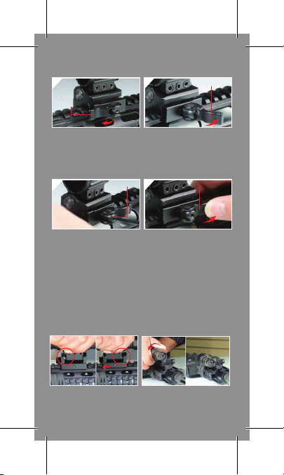
1
Cam
Lever
2
Cam Lever
Turn the Cam Lever leftward to
its unlocked position. Place
the QD mount on the Picatinny rail
at a desired position. Seat
the cross bolt at the bottom of
the ring into a selected
Picatinny slot.
3
Use the included Allen wrench to
adjust the Hex Screw at the side
of the cam for proper tension and
fit against the rail. Adjust
clockwise to increase the tension
and tighten the clamping width.
Adjust counter-clockwise to
decrease the tension and
increase the clamping width.
Hex Screw
FLIP-TO-SIDE FEATURE
To flip the ring to its alternate
position, firmly grasp the complete
lighting device mounted with the
ring and pull it backward against
the spring-loaded mounting base.
Turn the Cam Lever from left to
right to begin locking the QD
mount on the rail, but do not
complete the locking motion,
leaving some travel distance to
allow for adjustment.
4
The optimal tension is achieved
when the side plate first makes
contact with the Picatinny rail while
the Cam Lever still has enough
travel left for you to securely snap
into its locking position. Once you
achieve the optimal tension, push
the Cam Lever all the way to
the right for a positive lock onto the
rail. You may repeat Step 2 and 3 if
needed to find the best clamping
tension and locking position for your
mount on the rail.
Maintain force on the ring and flip
the ring sideways until it snaps into
place. Use the same method when
flipping the ring upward.
Cam Lever
CAUTION: The flip-to-side feature is built on a very robust base with
strong spring tension for repeated use. DO NOT attempt to flip the
ring sideways or upward when it is not mounted on your firearm with
a flashlight or laser.
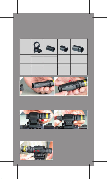
1
1.Remove the end cap of the lighting device.
2.Slide the appropriate insert(s) over the body of the light device.
The end with flange goes on first toward the front of the lighting
device. If using 2 inserts, slide Insert A over the light body first,
followed by Insert B.
3 4
3.Slide the tube of the lighting device, with inserts if applicable, into
the ring and replace the end cap.
4.Ensure inserts are mounted flush against the ring. Adjust the ring
mount position on the tube.
5
INSTALLATION GUIDE
Compatible UTG Products
Item
RG-FL25QS
RG-FL27QS
With Thick Insert
No Insert
(A)
Fits 20mm Tube
Fits 25mm Tube
LT-EL268Q
SCP-LS269
LT-TL099PR2
SCP-LS279
LT-ZL168
SCP-LS288
Fits 27mm Tube Fits 25mm Tube Fits 20mm Tube
LT-EL228Q
N/A
LT-EL338Q
LT-ELF240
LT-ZL337Q
2
5.Tighten the 3 locking screws
with the included Allen wrench in
an alternating pattern to complete
installation. Do not over-tighten
the screws.
With Thin Insert
(B)
N/A
LT-EL268Q
LT-TL099PR2
LT-ZL168
With Both Inserts
(B) Over (A)
N/A
SCP-LS269
SCP-LS279
SCP-LS288
MUM031011210
 Loading...