


ENJOY YOUR BOOKS
PLEASE VISIT OUR STORE FOR EVEN MORE GREAT
STUFF!
WWW.EVERYTHING4LESSSTORE.COM
COPYRIGHT NOTICE
ALL MATERIALS INCLUDING CD/DVD AND PDF
FILES ARE COPYRIGHTED
WWW.EVERYTHING4LESSSTORE.COM VON WALTHOUR PRODUCTIONS AND MAY NOT BE REPRODUCED, COPIED OR RESOLD UNDER ANY CIRCUMSTANCES. YOU MAY HOWEVER MAKE A COPY FOR YOUR OWN PERSONAL BACKUP. MATERIALS ARE FOR PERSONAL USE ONLY.
IF YOU PURCHASED THIS FROM ANYWHERE BUT FROM US PLEASE NOTIFY US IMMEDIATELY SO THAT WE MAY CHECK IF YOU PURCHASED FROM AN AUTHORIZED RESELLER SO WE CAN LET YOU KNOW IF YOU NEED TO RETURN FOR FULL REFUND FROM AN UNAUTHORIZED SELLER.
THANKS AGAIN AND PLEASE TAKE THE TIME TO
VISIT OUR STORE.
ATTENTION! EVERYTHING ON SALE NOW!!

WARNING!
THE SERVICING INSTRUCTIONS CONTAINED IN THIS MANUAL ARE FOR USE BY QUALIFIED PERSONNEL ONLY. TO AVOID ELECTRIC SHOCK, DO NOT PERFORM ANY SERVICING OTHER THAN THAT CONTAINED IN THE OPERATING INSTRUCTIONS UNLESS YOU ARE QUALIFIED TO DO SO.
TABLE OF CONTENTS (Continued) |
|
3-4 CALIBRATION OUTPUT ADJUSTMENT ...................................................................................................... |
30 |
3-5 A TIMEBASE ALIGNMENT ........................................................................................................................... |
30 |
3-5-1 Slow Sweep Time ................................................................................................................................. |
30 |
3-5-2 Sweep Length ....................................................................................................................................... |
30 |
3-5-3 Fast Sweep Time .................................................................................................................................. |
30 |
3-5-4 Sweep Start Point ................................................................................................................................. |
30 |
3-5-5 Timebase Accuracy Check .................................................................................................................... |
30 |
3-6 A TIMEBASE X10 MAGNIFIER ADJUSTMENT ........................................................................................... |
30 |
3-6-1 Magnifier Positioning ........................................................................................................................... |
30 |
3-6-2 Magnifier Speed Accuracy .................................................................................................................... |
30 |
3-7 B TIMEBASE ALIGNMENT ........................................................................................................................... |
30 |
3-7-1 Slow Sweep Time ................................................................................................................................. |
30 |
3-7-2 Length Adjustment ............................................................................................................................... |
31 |
3-7-3 Sweep Start Point ................................................................................................................................. |
31 |
3-7-4 Fast Sweep Time .................................................................................................................................. |
31 |
3-7-5 Timebase Accuracy Check .................................................................................................................... |
31 |
3-7-6 Start Points Alignment .......................................................................................................................... |
31 |
3-8 VERTICAL AMPLIFIERS ............................................................................................................................... |
31 |
3-8-1 DC Balance Adjustment ........................................................................................................................ |
31 |
3-8-2 Attenuator Step Balance ........................................................................................................................ |
30 |
3-8-3 X1 AC Gain Compensation ................................................................................................................... |
31 |
3-8-4 X10 AC Gain Compensation ................................................................................................................. |
31 |
3-8-5 Gain Calibration ................................................................................................................................... |
31 |
3-8-6 CH-2 Invert Balance Adjustment ........................................................................................................... |
32 |
3-8-7 CH-1/CH-2 Input Capacitance Adjustment ............................................................................................ |
32 |
3-8-8 CH-1/CH-2 Input Attenuator Compensation .......................................................................................... |
32 |
3-8-9 CH-3 Direct Input Capacitance Adjustment ........................................................................................... |
32 |
3-8-10 CH-3 Attenuator Compensation .......................................................................................................... |
32 |
3-8-11 CH-3 Attenuator Input Capacitance Adjustment ................................................................................... |
32 |
3-8-12 CH-3 Gain Adjustment ....................................................................................................................... |
32 |
3-8-13 CH-1 Output Level Adjustment ........................................................................................................... |
32 |
3-8-14 CH-1/CH-2 HF Pulse Response Alignment .......................................................................................... |
32 |
3-8-15 CH-1/CH-2 Frequency Response Check .............................................................................................. |
33 |
3-8-16 CH-1 Output Pulse Response .............................................................................................................. |
33 |
3-8-17 CH-1/CH-2 X10 Magnifier Bandwidth Check ..................................................................................... |
33 |
3-8-18 Vertical Position Control Centering ..................................................................................................... |
33 |
3-8-19 ADD Balance Adjustment ................................................................................................................... |
33 |
3-9 TRIGGER CIRCUITRY ADJUSTMENTS ....................................................................................................... |
33 |
3-9-1 Trigger Balance and Centering Alignments ........................................................................................... |
33 |
3-9-2 Trigger Balance Adjustments for Multitrace Modes ............................................................................... |
33 |
3-9-3 Preset Trigger Adjustment .................................................................................................................... |
34 |
3-9-4 CH-3 Pulse Response Adjustment ......................................................................................................... |
34 |
3-9-5 Internal Trigger-Pulse Response Adjustment ......................................................................................... |
34 |
3-10 X-Y MODE ADJUSTMENTS .................................................................................................................. |
34 |
3-10-1 Gain Adjustment .................................................................................................................................... |
34 |
3-10-2 Balance Adjustment ............................................................................................................................... |
34 |
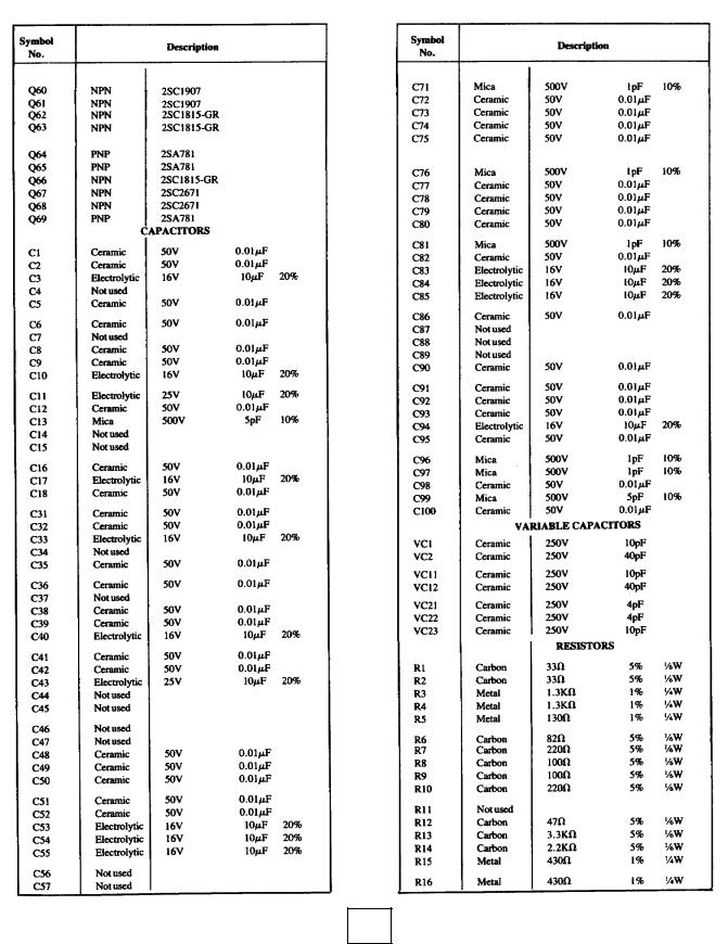
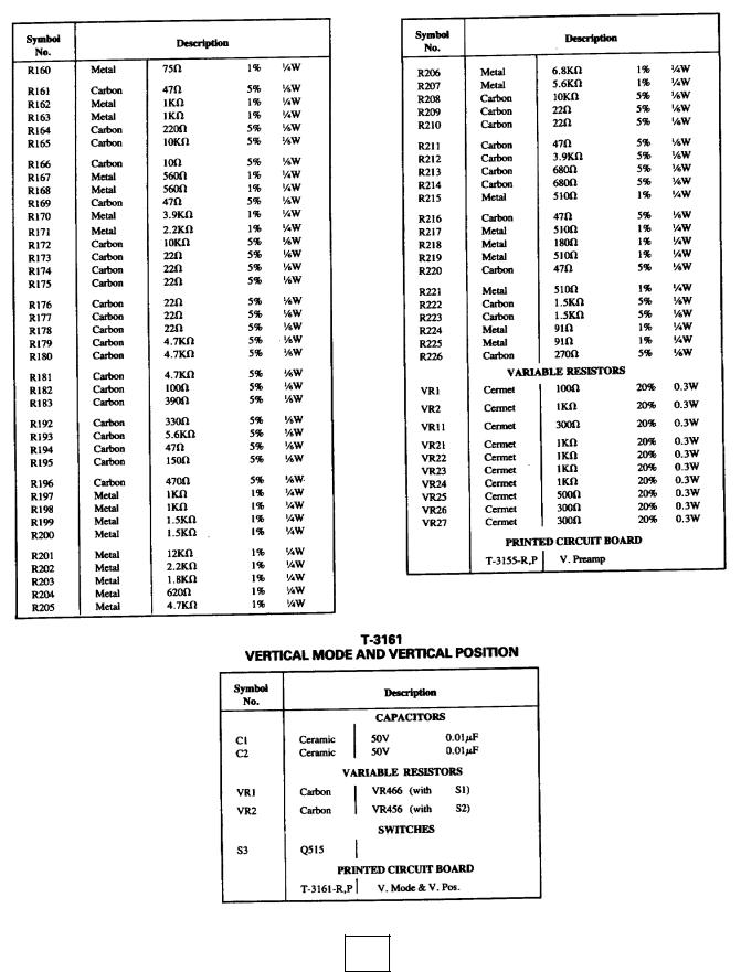
4. REPLACEMENT PARTS LIST |
37 |
5. BLOCK DIAGRAM, SCHEMATICS AND P.C. BOARDS |
51 |
3. MAINTENANCE AND CALIBRATION
|
|
|
|
A TIME/DIV switch .................... |
.5 mS |
|
|||
3-0. The following test equipment is required to perform the |
|
B TIME/DIV switch .................... |
.1 mS |
|
|||||
|
A VARIABLE control |
Clockwise |
|||||||
calibration/maintenance procedures described in this section. |
|
||||||||
|
Horizontal POSITION control |
Centered* |
|
||||||
The performance specifications given are the minimum |
|
|
|||||||
|
* Adjusted afterwards for best viewing. |
|
|||||||
necessary to accurately calibrate the oscilloscope. |
|
|
|||||||
Description |
Minimum Specifications |
|
Allow 30 minutes warmup before making |
any adjust- |
|||||
1. Digital Voltmeter |
DC Voltage Range: 0-200 VDC |
|
|||||||
|
ments. Remove the top and bottom covers to gain access to test |
||||||||
|
Accuracy: +0.5% |
|
|||||||
|
|
points and internal adjustments. |
|
|
|||||
2. High Voltage |
DC Voltage Range: 0-2000 VDC |
|
|
|
|||||
|
|
|
|
|
|
|
|||
Voltmeter |
Accuracy: -+ 1% |
|
3-2 POWER SUPPLY CHECK AND ADJUSTMENT |
||||||
3. Frequency Counter |
Frequency Range: 100 Hz - |
|
|||||||
|
200 MHz |
|
3-2-1 |
-8 Volt Adjustment |
|
|
|
||
|
Overall Accuracy: +0.001% |
|
|
|
|||||
4. Time Mark Generator |
Marker Outputs: 2nS - 0.5 S with |
|
Connect a digital voltmeter's positive lead to the scope |
||||||
|
chassis (GND), and the voltmeter's negative lead to TP-5 lo- |
||||||||
|
calibrated + 5% offset adjust |
|
|||||||
|
|
cated on PCB T-3153. Adjust VR-1 for -8.0 V. |
|
||||||
|
Accuracy: -+0.1% |
|
|
||||||
|
|
|
|
|
|
|
|
||
5. Sine Wave Generator |
Frequency Range: lkHz - 200 kHz |
3-2-2 |
Power Supply Check |
|
|
|
|||
|
Output Level: 15 mV - 5 Vp.p |
|
|
|
|||||
|
|
Check the |
voltages listed below |
by |
moving the |
||||
|
Accuracy: -+.3 dB, 1 MHz - 200 |
|
|||||||
|
|
voltmeter's negative lead to chassis ground, and applying the |
|||||||
|
MHz as frequency is changed |
|
|||||||
|
|
positive lead, in turn, to each of the associated test points on |
|||||||
|
|
|
|
||||||
6. Test Oscilloscope |
100 MHz Bandwidth |
|
PCB T-3153. |
Nominal |
|
|
|
||
|
|
|
|
|
|
||||
7. Square Wave |
Frequency: 1 kHz - 100kHz, -+1% |
|
|
|
|
|
|
||
|
Test Point |
Voltage |
Tolerance |
||||||
Generator |
Output Level: I mV - 1.0 Vp-p, |
|
|||||||
|
TP-I |
+100 |
+98 VDC |
'to |
102VDC |
||||
|
-+1% |
|
|
||||||
|
|
|
TP-2 |
+ 50 |
49 |
|
51 |
||
|
Rise Time: 3 nS |
|
|
||||||
|
|
TP-3 |
+ 12 |
11.75 |
|
12.25 |
|||
8. Amplitude Calibrator |
Output: 1 kHz square wave |
|
|
||||||
|
TP-4 |
+ 8 |
7.85 |
|
8.15 |
||||
|
Frequency Accuracy: -+0.25% |
|
|
||||||
|
|
TP-6 |
+ 5 |
4.8 |
|
5.2 |
|||
|
Output Level: 2 mV - 20 Vp-p |
|
|
||||||
|
|
TP-7 |
+ 19 |
17.5 |
|
20.5 |
|||
9. Capacitance Meter |
Range: 0-50 pF |
|
|
||||||
|
|
|
|
|
|
|
|||
|
Accuracy: --- |
1% |
|
3-2-3 High-Voltage Adjustment |
|
|
|||
|
|
|
|
|
|
||||
3-1. INITIAL SETUP CONDITIONS |
|
|
Turn off the unit under test. Connect the positive lead of a |
||||||
|
|
HV voltmeter to chassis ground, and its negative lead to TP-8. |
|||||||
POWER switch ......................…………Pushed in |
|
||||||||
|
Turn the scope on and allow a 2 minute warmup. Adjust VR-2 |
||||||||
A INTEN control |
|
Centered* |
|
||||||
|
|
on PCB T-3162 for a reading of - 1950 volts. Connect an X10 |
|||||||
B INTEN control |
|
Centered* |
|
||||||
|
|
probe to the test oscilloscope and hold its tip close to the face |
|||||||
ILLUM control |
|
Clockwise |
|
||||||
|
|
of the CRT under test. The high-voltage ripple displayed on |
|||||||
FOCUS control |
|
Centered* |
|
||||||
|
|
the test oscilloscope should be less than 0.1Vp-p. |
|
||||||
AC/GND/DC switches |
|
DC |
|
|
|||||
|
|
3-3. CRT CONTROL ADJUSTMENTS |
|
|
|||||
VOLTS/DIV switches |
|
20mV |
|
|
|
||||
|
|
Make sure |
the controls |
are set according to the initial |
|||||
VARIABLE controls |
|
Clockwise |
|
||||||
|
|
setup conditions in Paragraph 3-1 before starting the following |
|||||||
|
|
|
|
||||||
X10 MAG switches ………………… |
Pushed in |
|
adjustments. |
|
|
|
|
||
|
3-3-1 Intensity Range Adjustment. |
|
|
||||||
Vertical POSITION controls ......…… |
Centered*. |
|
|
|
|||||
|
Center the CH- 1 trace on the CRT with the vertical |
||||||||
PULL QUAD control ...............… |
Pushed in |
|
|||||||
|
POSITION control. Set the A INTEN control knob mark to an |
||||||||
PULL TRIPLE control ...............… |
Pushed in |
|
|||||||
|
approximate 45° angle as shown in Figure 3-1. Adjust VR-I on |
||||||||
V MODE switches ...................... |
… |
CH-1 |
|
||||||
CH-2 INV switch ....................... |
…… |
Out |
|
PCB T-3162 until the trace becomes just barely visible. |
|||||
DLY TIME MULT control .........…… Counterclockwise. |
|
3-3-2 Astigmatism Adjustment |
|
|
|||||
COUPLING switch ...................…… |
AC |
|
Connect a sine wave generator to the CH-1 input connec- |
||||||
SOURCE switch ......................……….CH-1 |
|
tor. Set generator frequency and output to produce five or six |
|||||||
LEVEL control ........................………. |
0 |
|
sine waves. Set output level and POSITION controls for a |
||||||
HOLDOFF control ..................... |
|
Detented counter |
|
centered display 6 cm high. (Peaks of the sine waves just |
|||||
|
|
clockwise and |
|
touching the graticule lines I cm above and below the bottom |
|||||
|
|
pulled out |
|
and topmost graticule lines.) Adjust A INTENS and FOCUS |
|||||
A/B TRACE SEP control .............. |
|
Centered |
|
for a medium-bright, sharp display. Adjust VR- 1 on PCB T- |
|||||
SLOPE switch ........................... |
|
Out |
|
3157 for optimum overall sharpness. |
|
|
|||
HORIZ DISPLAY switches. |
.......... |
A |
|
|
|
|
|
|
|
START switch .......................... |
|
Out |
|
|
|
|
|
|
|
SWEEP MODE switches |
|
AUTO |
|
|
|
|
|
|
|
|
29 |
|
|
|
|
|
|
||
|
|
|
|
|
|
|
|
|
|
|
|
|
|
|
|
|
|
|
|

3-4. CALIBRATION OUTPUT ADJUSTMENT
Connect the test oscilloscope to the CAL connector on the fron panel of the LBO-516. Adjust VR-1 on PCB T-3287 for a CAL output level of 0.5 Vp-p +-1%. The duty cycle of the square wave should be 45-55%.
Connect the CAL output to a frequency counter; the frequency should be 1000 Hz + - 10%.
3-5. A TIMEBASE ALIGNMENT
3.5-1 Slow Sweep Time
Return the oscilloscope to the initial setup conditions. (See Paragraph 3-1). Adjust the time-mark generator for an output of .5 mS and connect it to the CH-1 input connector. Using the horizontal POSITION control, align the first mark with the leftmost vertical graticule line. Adjust VR-22 on PCB T-3158 to align each subsequent mark with a major vertical graticule line.
3.5-2 Sweep Length
With the same conditions as in the previous paragraph, adjust the horizontal POSITION control to align the third mark with the leftmost vertical graticule line. (See Figure 3-2.) Adjust VR-1 on PCB T-3158 so the 13th mark is fully displayed on the CRT screen.
3.5-3 Fast Sweep Time
Return the oscilloscope to the initial setup conditions. (See Paragraph 3-1). Set the A TIME/DIV switch to 0.5 PS.
Set the time-mark generator to 0.5/.PS and connect it to the CH- 1 input connector. Using the horizontal POSITION control, align the first mark with the leftmost vertical graticule line. (See Figure 3-2.) Adjust VC-22 on PCB T-3158 to align each subsequent mark with a major vertical graticule line.
3.5-4 Sweep Start Point
Return the oscilloscope to the initial setup conditions. (See Paragraph 3-1). Set the A TIME/DIV switch to 0.1 mS. With the horizontal POSITION control, adjust the trace startpoint to the first minor division (0,2 major division). Change the A T1ME/DIV switch to 50/aS and adjust VC-1 on PCB T-3158 so the sweep starts at the leftmost vertical graticule line.
3.5-5 Timebase Accuracy Check
Return the oscilloscope to the initial setup conditions. (See Paragraph 3-1). Set the A TIME/DIV switch to 0.5 S. Set
the time-mark generator to 0.5 S and connect it to the CH- 1 input connector. Align the first mark with the left-most vertical graticule line. Adjust the generator so that each subsequent mark is aligned with a major vertical graticule line. Repeat for
each A TIME/DIV switch setting from.2 S to 0.2PS, verifying that the timebase accuracy is within +-2% at each sweep speed.
3-6. A TIMEBASE X10 MAGNIFIER ADJUSTMENT
3-6-1 Magnifier Positioning
Return the oscilloscope to the initial setup conditions. (See Paragraph 3-1.) Set the CH-1 AC/GND/DC switch to GND, and press the INTEN BY B pushbutton. Set the B TIME/DIV switch to .5 mS. Adjust the horizontal POSITION control to start the A trace on the leftmost vertical graticule line. Adjust the DLY TIME MULT control to start the B (intensified) trace at the center vertical graticule line. Center the horizontal POSITION control knob. Pull the timebase X10 MAG switch. Adjust VR-33 on PCB T-3158 so that the B sweep starts on the center graticule line. Afterward, push in the X 10 MAG switch knob, and adjust VR-34 on PCB T-3158 so that the B sweep starts on the center graticule line. Repeat these two adjustments (VR-33 and VR-34) until the B trace starts on the center graticule line in both positions of the XI0 MAG switch.
3-6-2 Magnifier Speed Accuracy
Return the oscilloscope to the initial setup conditions. (See Paragraph 3-1). Connect a time-mark generator set for. 5 mS output to the CH-1 input connector. Set the A TIME/DIV switch and horizontal POSITION control so every third mark is aligned with a major vertical graticule line. Pull the X10 MAG knob, then adjust VR-35 on PCB T-3158 so a mark is aligned with the first, center, and last major vertical graticule line.
3-7. B TIMEBASE ALIGNMENT
3-7-1 Slow Sweep Time
Return the oscilloscope to the initial setup conditions. (See Paragraph 3-1.) Set the CH-1 VOLTS/DIV switch to. 1 V. Connect a time-mark generator set for .5 mS to the CH-1 input connector. Set the DLY TIME MULT control to 2.50, and press the B HORIZ DISPLAY pushbutton. Adjust the DLY TIME MULT control to align the nearest mark with the
30

leftmost vertical graticule line. Adjust VR-21 on PCB T-3158 to align each of the subsequent marks with a major vertical graticule line.
3-7-2 Length Adjustment
Return the oscilloscope to the initial setup conditions. (See Paragraph 3-1.) Connect a time-mark generator set for 0.5 mS to the CH- 1 input connector. Using the horizontal POSITION control, align the third mark with the leftmost vertical graticule line, and adjust VR-11 on PCB T-3158 so that the 13th mark is fully displayed on the CRT screen.
3-7-3 Sweep StartPoint
Return the oscilloscope to the initial setup conditions. (See Paragraph 3-1.) Press the B HORIZ DISPLAY pushbutton. Using the horizontal POSITION control, adjust the trace start point to a little less than the first minor division on the center horizontal graticule line (0.15 major division).
Change the B TIME/DIV switch to 50 PS, then adjust VC11 on PCB T-3158 so the sweep starts at the leftmost vertical graticule line.
3-7-4 Fast Sweep Time
Return the oscilloscope to the initial setup conditions. (See Paragraph 3-1.) Set the A TIME/DIV switch to PS, and
the B TIME/DIV switch to 0.5PS. Press the B HORIZ DISPLAY pushbutton. Connect a time-mark generator set for
0.5PS output to the CH-1 input connector. With the horizontal POSITION control, align the first mark with the leftmost vertical graticule line. Adjust VC-21 on PCB T-3158 to align each of the subsequent marks with the other vertical graticule lines.
3-7-5 Timebase Accuracy Check
Return the oscilloscope to the initial setup conditions. (See Paragraph 3-1.) Set the A and B TIME/DIV switches to 50 mS, and press the B HORIZ DISPLAY pushbutton. Connect a time-mark generator set for 50 mS output to the CH- 1 input connector. Align the first mark with the leftmost vertical graticule line. Adjust the generator so each subsequent mark is aligned with a major vertical graticule line. Repeat the
above for each TIME/DIV setting from 20 mS to .02PS, verifying that the timebase accuracy is within +-2% at each sweep speed.
3-7-6 Start Points Alignment
Return the oscilloscope to the initial setup conditions. (See Paragraph 3-1). Set the CH- 1 AC/GND/DC switch to
GND, and the B TIME/DIV switch to 5PS. Press the INTEN BY B HORIZ DISPLAY pushbutton, and adjust the A and B INTEN controls for a noticeable difference between the A and B traces. Using the horizontal POSITION control, make the A trace start at the leftmost vertical graticule line. Check that the DLY TIME MULT control is set at 0.2 (fully CCW), then adjust VR-13 on PCB T-3158 so that the B trace starts at the
first minor vertical graticule line.
Turn the DLY TIME MULT control to 10.0 and adjust VR-12 on PC T-3158 to make the B trace start at the rightmost vertical graticule line. Repeat both of these adjustments until the B trace starts at the proper points.
3-8. VERTICAL AMPLIFIERS
3-8-1 DC Balance Adjustment
Retain the oscilloscope to the initial setup conditions. (See Paragraph 3-1). Set the CH-1 and CH-2 VOLTS/DB/ switches to 5 reV, the CH-I and CH-2 AC/GND/DC switches to GND, and center the trace vertically with the vertical POSITION control. Then, pull the CH-I X10 MAG switch
knob, and adjust VR-5 on PCB T-3154 to recenter the trace. Repeat the above by turning the X10 MAG switch on and off, and readjusting the vertical POSITION control and VR-5 for minimum shift.
Press the CH-2 V MODE pushbutton, and repeat the above procedure for CH-2. VR-15 on PCB T-3154 is the CH-2 adjustment.
3-8-2 Attenuator Step Balance
Return the oscilloscope to the initial setup conditions. (See Paragraph 3-1). Set the CH-I and CH-2 VOLTS/DIV switches to 10 mV, and the AC/GND/DC switches to GND. Center the trace vertically using the CH-I vertical POSITION control. Change the CH-1 VOLTS/DIV switch to 5 mV, and adjust VR4 on PCB T-3154 to recenter the trace. Repeat the above until there is very little shift in the trace when switching between I0 mV and 5 mV positions of the VOLTS/DIV switch.
Press the CH-2 V MODE pushbutton, and repeat the above procedure for CH-2. VR-14 on PCB T-3154 is the CH-2 adjustment.
3-8-3 X1 AC Gain Compensation
Return the oscilloscope to the initial setup conditions. (See Paragraph 3-1). Set the CH-1 and CH-2 VOLTS/DIV switches to 5 mV, the A TIME/DIV switch to .2 mS, and press the ALT V MODE pushbutton.
Connect a square-wave generator to the CH-1 and CH-2 input connectors. Adjust the generator frequency to I000 Hz, and its output level to 25 mVp-p.Adjust VR- 1 on PCB T-3154 for a correct square-wave display, per Figure 3-3. After channel 1 is compensated, adjust VR-11 on PCB T-3154 for a correct channel 2 display.
3-8-4 X10 AC Gain Compensation
With conditions set as in Paragraph 3-8-3, turn both VOLTS/DB/switches to 20 mV and pull both vertical X10 MAG control knobs. Set the square-wave generator output to 10 mVp-p.
Adjust VR-2 on PCB T-3154 for a correct square-wave display, per Figure 3-3. After channel 1 is compensated, adjust VR-12 on PCB T-3154 for a correct CH-2 display.
3-8-5 Gain Calibration
With conditions set as in Paragraph 3-8-4, turn both VOLTS/DIV switches to 5 mV, and remove the square wave generator.
Connect an amplitude calibrator whose output is set for 25 mVp-p to the CH-1 and CH-2 input connectors. Adjust VR21 on PCB T-3155 for a CH-1 vertical deflection of~ major divisions. Adjust VR-23 on PCB T-3155 for a CH-2 vertical deflection of 5 major divisions.
31

3-8-6 CH-2 INV Balance Adjustment
Return the oscilloscope to the initial setup conditions. (See Paragraph 3-1.) Press the CH-2 V MODE switch, and set the CH-2 AC/GND/DC switch to GND.
Center the trace vertically using the CH-2 vertical POSITION control. Press the CH-2 INV switch, and note the amount that the trace shifts from the centered position. Using VR-11 on PCB T-3155, move the trace half the distance it shifted, back towards the center of the CRT screen. Release the CH-2 INV switch, and recenter the trace with the CH-2 vertical POSITION control. Repeat the above adjustments as the CH-2 INV switch is operated, until there is no trace shift from one position to the other.
3-8-7 CH-1/CH-2 Input Capacitance Adjustment
Return the oscilloscope to the initial setup conditions. (See Paragraph 3-1). Set the VOLTS/DIV switches to 5mV.
Connect a capacitance meter to the CH-1 input connector and adjust VC-1 (Ci-1) on PCB T-3154 for 30 pF. Reset the VOLTS/DIV switch to 20 mV and adjust 1/2 Ci for 30 pF. Reset the VOLTS/DIV switch to 50 mV and adjust 1/5 Ci for 30 pF. Reset the VOLTS/DIV switch to .1 V and adjust l/l0 Ci for 30 pF. Reset the VOLTS/DIV switch to 1 V and adjust 1/100 Ci for 30 pF.
Press the CH-2 V MODE pushbutton, and repeat the above adjustments on VC-11 for channel 2.
3-8-8 CH-1/CH-2 Input Attenuator Compensation
Return the oscilloscope to the initial setup conditions. (See Paragraph 3-1). Connect a square-wave generator to the CH-1 input connector. Set the generator controls for 100 mV output at 1000 Hz.
Adjust CH-1 1/2Cc on PCB T-3154 for a correctly compensated square-wave. (See Figure 3-3.) Reset the CH-1 VOLTS/DIV switch to 50 mV, and the generator output level for 250 mVp-p. Adjust CH-1 1/5Cc on PCB T-3154 for a correctly compensated square wave. Reset the CH-1 VOLTS/ DIV switch to .1 V, and the generator output level to .5 V. Adjust CH-1 1/10Cc on PCB T-3154 for a correctly compensated square-wave. Reset the CH- 1 VOLTS/DIV switch to 1 V, and the generator output level to 5 Vp-p. Adjust CH-1 1/100Cc for a correctly compensated squarewave.
Press the CH-2 V MODE switch, and repeat the above procedure for CH-2, using the CH-2 1/2Cc, 1/5Cc, 1/10Cc. and 1/100Cc adjustment trimmers.
3-8-9 CH-3 Direct Input Capacitance Adjustment
Return the oscilloscope to the initial setup conditions. (See Paragraph 3-1.) Press the ALT V MODE pushbutton, pull the PULL TRIPLE control knob, set the SOURCE switch to .2 V/DIV, and the COUPLING switch to DC.
Connect a capacitance meter to the CH-3 input connector. Adjust VC-5 (C IN) on PCB T-3153 for a 30 pF indication.
3-8-10 CH-3 Attenuator Compensation
With conditions set as in Paragraph 3-8-9, reset the SOURCE switch to 2 V/DIV. Connect a square-wave generator to the CH-3 input connector. Set the generator controls for 10 Vp.p output at 1000 Hz.
Adjust VC-3 (CC) on PCB T-3153 for a correctly compensated squarewave, per Figure 3-3.
3-8-11 CH-3 Attenuator Input Capacitance Adjustment
With conditions set as in Paragraph 3-8-10, remove the square-wave generator and connect a capacitance meter to the CH-3 input connector. Adjust VC-3 (C-l) for 30pF meter indication.
3-8-12 CH-3 Gain Adjustment
With conditions set as in Paragraph 3-8-11, remove the capacitance meter and connect an amplitude calibrator to the CH-3 input connector. Set the calibrator controls for 1 Vp-p output at 1000 Hz. Adjust VR-26 on PCB T-3155 for 5 major divisions of vertical deflection on the CRT screen.
3-8-13 CH-1 Output Level Adjustment
Return the oscilloscope to the initial setup conditions. (See Paragraph 3-1.) Connect the CH-1 OUTPUT connector to a test oscilloscope having a 50-ohm feedthrough termination on its input. Set the test oscilloscope's input attenuator at 20 mV/div. Connect an amplitude calibrator adjusted for an output level of 100 mVp-p at 1000 Hz to.the CH-1 input connector of the LBO516.Adjust the CH-1 VARIABLE control for 4 major divisions of vertical deflection on the LBO-516, then adjust VR- 1 on PCB T-3155 for 4 divisions of vertical deflection on the test oscilloscope.
Set the CH-1 AC/GND/DC switch to GND, and the CH-1 VARIABLE control to CAL'D. Make sure the test oscilloscope is DC coupled and its ground reference is known. Adjust VR-2 on PCB T-3155 for a 0 VDC output as indicated on the test oscilloscope.
3-8-14 CH-I/CH-2 HF Pulse Response Adjustment
Return the oscilloscope to the initial setup conditions. (See
32

Paragraph 3-1.) Set the CH-1 VOLTS/DIV switch to 5 mV, the A TIME/DIV switch to 2/aS, the B TIME/DIV switch to .2 PS, and press the INTEN BY B HORIZ DISPLAY pushbutton.
Connect a square-wave generator to the CH-1 input conneetor, and set the generator for 25 mVp-p output at 100 kHz. Adjust the DLY TIME MULT control so the B (intensified) trace is positioned over a leading edge of the displayed square wave. Press the B HORIZ DISPLAY pushbutton, and adjust VC-21 on PCB T-3155 and VC-1, VR-1, VC-2, VR-2, and VC- 3 on PCB T-3156 for minimum observed overshoot and ringing. This can be checked by setting the CH-1 VOLTS/ DIV switch to 20 mV and pulling the CH-1 X10 MAG knob.
Cheek that the overshoot and ringing is less than 3% at all positions of the CH-1 VOLTS/DIV switch. In each case the generator output level should be adjusted for 5 major divisions of vertical deflection.
Repeat the above procedure for CH-2. The corresponding adjustment parts for CH-2 are VC-11 and VC12 on PCB T- 3155, and VC-13 on PCB T-3154.
3-8-15 CH-1/CH-2 Frequency Response Check
Return the oscilloscope to the initial setup conditions. (See Paragraph 3-1.) Make sure the X10 MAG switches are pushed in. Set the VOLTS/DIV controls to 5 mV, and the A TIME/DIV switch to 2PS.
Connect a sine-wave generator to the CH-1 input connector, making sure the feedthrough termination appropriate for the generator is attached to the CH- 1 input connector. Adjust the generator for an output level of 40 mVp-p at 1 MHz; monitor the frequency with a frequency counter.
Increase the frequency until the display indicates 5.6 major divisions of vertical amplitude. This is the -3 dB point. The counter should indicate a frequency of over 100 MHz. Repeat the applicable adjustments in Paragraph 3-8-14 if it does not.
Move the generator to the CH-2 input connector, and press the CH-2 V MODE pushbutton. Set the SOURCE switch at CH- 2, and repeat the above procedure for channel 2.
3-8-16 CH-1 Output Pulse Response
With conditions set as in Paragraph 3-8-13, set the CH-1 VOLTS/DIV switch of LBO-516 and that of the test oscilloscope to 5 mV/div.
Connect a square-wave generator adjusted for an output frequency of I00 kHz to the CH-1 input connector. Adjust the generator output level for 4 divisions of vertical deflection on the test oscilloscope. Then, adjust VC- 1 and VC-2 on PCB T- 3155, and VC-3 on PCB T-3154 for less than 7% overshoot at the leading and trailing edges of the waveform displayed on the test oscilloscope.
3-8-17 CIt-1 & CH-2 Xl0 Magnifier Bandwidth Check
Return the oscilloscope to the initial setup conditions.(See Paragraph 3-1.) Set the A TIME/DIV switch to 2PS, and pull the CH-1 and CH-2 X10 MAG switch knobs.
Connect a sine-wave generator to the CH-1 input connector, and adjust it for 8 divisions deflection at 1 MHz. Monitor the generator frequency with a frequency counter. Increase the generator frequency until the displayed amplitude decreases to 5.6 divisions. This is the -3 dB point. The counter should indicate a frequency of over 5 MHz.
Move the generator to the CH-2 input Connector, and press the CH-2 V MODE pushbutton. Set the SOURCE switch at CH- 2, and repeat the above procedure for CH-2.
3-8-18 Vertical POSITION Control Centering
Return the oscilloscope to the initial setup conditions. (See Paragraph 3-1.) Press the ALT V MODE pushbutton, and pull the PULL TRIPLE control knob. Make sure the CH-1, CH-2, and CH-3 vertical POSITION control knobs are set with their index marks pointing straight up.
Adjust VR-22 on PCB T-3155 to position the CH-1 trace on the center horizontal graticule line. Adjust VR-24 on PCB T- 3155 to position the CH-2 trace on the center horizontal graticule line. Adjust VR-25 to position the CH-3 trace on the center horizontal graticule line.
3-8-19 ADD Balance Adjustment
With conditions set as in Paragraph 3-8-18, push in the ADD V MODE pushbutton. Adjust VR-27 on PCB T-3155 to position the trace on the center horizontal graticule line.
3-9 TRIGGER CIRCUITRY ADJUSTMENTS 3-9-1 Trigger Balance and Centering Adjustments
Return the oscilloscope to the initial setup conditions. (See Paragraph 3-1.) Set the CH-1 AC/GND/DC switch to AC, the COUPLING switch to DC, and the A TIME/DIV switch to .2 mS.
Connect a sine-wave generator set for 1.2 Vp-p output at 1000 Hz to the CH-1 input connector. Make sure the LEVEL control is centered (index mark up), and center the displayed sine wave by means of the CH-1 vertical POSITION control so the waveform extends from 3 major divisions above to 3 major divisions below the center horizontal graticule line. Adjust the horizontal POSITION control so the sweep starts on the first vertical graticule line. Adjust VR-21 on PCB T-3153 for symmetrical trigger points (above and below the center horizontal graticule line) when the SLOPE switch is changed from + to -. (See Figure 3-4.)
Adjust VR-32 on PCB T-3153 until the trigger point of the displayed sine wave starts on the center horizontal graticule line when the SLOPE switch is changed from + to -.
Reduce the output of the generator so the displayed sine wave's p-p amplitude is only 0.4 (2 minor) divisions. Then fine adjust VR-I and VR-12 on PCB T-3153 for a stable display in each position of the SLOPE switch.
3-9-2 Trigger Balance Adjustments for Multitrace Modes
Return the oscilloscope to the initial setup conditions (See Paragraph 3-1.) Set the AC/GND/DC switches to GND, press the ALT V MODE pushbutton, pull the PULL TRIPLE control knob, and set the SOURCE switch to CH-2.
Turn the CH-1 vertical POSITION control fully counterclockwise, and center the CH-3 trace with the CH-3 vertical POSITION control. Change the COUPLING switch to DC and adjust VR-22 on PCB T-3153 to recenter the trace.
Set the SOURCE switch to .2 V/DIV and adjust VR-23 on PCB T-3153 to recenter the trace. Reset the AC/GND/DC switches to AC and recenter the trace if necessary.
Restore the COUPLING switch to AC and recenter the trace with VR-31 on PCB T-3153.
33

3-9-3 PRESET Trigger Adjustment
Return the oscilloscope to the initial setup conditions. (See Paragraph 3-1.) Connect a sine-wave generator to the CH-1 input connector. Adjust the generator output for 2 minor divisions of vertical deflection at I000 Hz. Pull the HOLDOFF control for PRESET trigger. Adjust VR-2 on PCB T-3159 until the waveform is triggered and the TRIG'D lamp lights.
3-9-4 CH-3 Pulse Response Adjustment
Return the oscilloscope to the initial setup conditions. (See Paragraph 3-1.) Press the ALT V MODE pushbutton, pull the PULL TRIPLE control knob, set the COUPLING switch to DC, and the SOURCE switch to.2 V/DIV. Center the CH-3 trace.
Connect a square-wave generator to the CH-3 input connector. Set the generator for 1 Vp-p output level at 100 kHZ. Adjust VC-6 on PCB T-3153 and VC-23 on PCB T-3155 to reduce overshoot and ringing to below 10%. Check the frequency response of CH-3 in the same manner as was done in Paragraph 3-8-15.
3-9-5 Interred Trigger-Pulse Response Adjustment
Return the oscilloscope to the initial setup conditions. (See Paragraph 3-1.) Set the VOLTS/DIV switches to 5 mV, the COUPLING switch to DC, and press the ALT V MODE pushbutton.
Connect a square-wave generator set for 25 mVp-p output at I00 kHz to the CH-1 input connector. Adjust VC-I on PCB T- 3153 to minimize overshoot and ringing. Total overshoot and ringing should be less than 10%.
Repeat the above procedure for channel 2, adjusting VC-2 on PCB T-3153.
3-10. X-Y MODE ADJUSTMENTS
3-10-1 Gain Adjustment
Return the oscilloscope to the initial setup conditions. (See Paragraph 3-1.) Press the X-Y pushbutton.
Connect a square-wave generator set for 100mVp-p output at 1000 Hz to the CH-1 (X IN) connector. Adjust VR-31 on PCB T-3158 for 5 major divisions of separation between the two dots displayed on the CRT screen. (Note: the position of the dots will change when adjusting VR-31; this is normal.)
3-10-2 Balance Adjustment
With conditions set as in Paragraph 3-10-1, set both AC/ GND/DC switches to GND. Check that the horizontal POSITION and X FINE control knobs are set with their index marks up, then adjust VR-32 on PCB T-3158 to center the dot horizontally on the CRT screen.
34
35

36

37
38

39
40
 Loading...