

Page 1
USER´S MANUAL
BEDIENUNGSANLEITUNG
MANUEL D`UTILISATION
MANUAL DE USUARIO
INSTRUKCJA OBSŁUGI
MANUALE D‘ USO
2-ZONE rack mixer
LDzone622
Page 2
ENGLISHDEUTSCHFRANCAIS
You‘ve made the right choice!
We have designed this product to operate reliably over many years. LD Systems stands for this with its name and
many years of experience as a manufacturer of high-quality audio products.
Please read this User‘s Manual carefully, so that you can begin making optimum use of your LD Systems product
quickly.
You can find more information about LD SYSTEMS at our Internet site WWW.LD-SYSTEMS.COM
Introduction
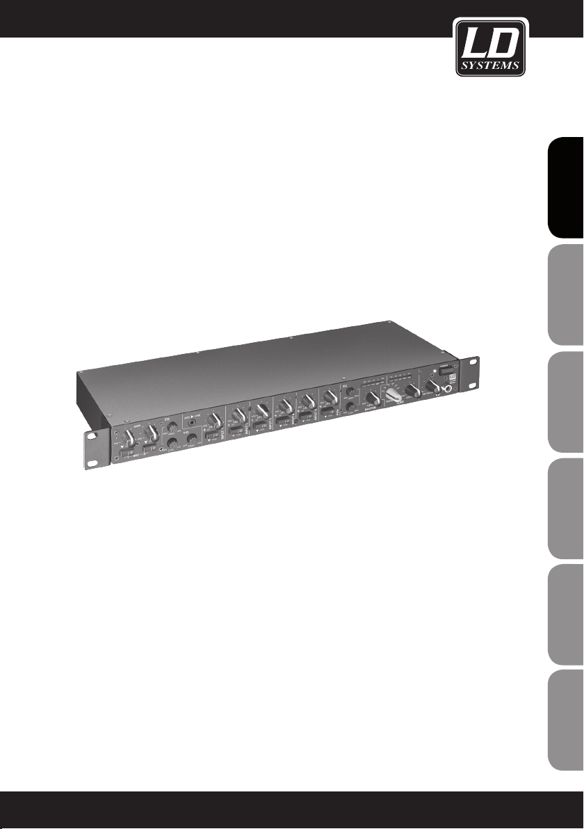
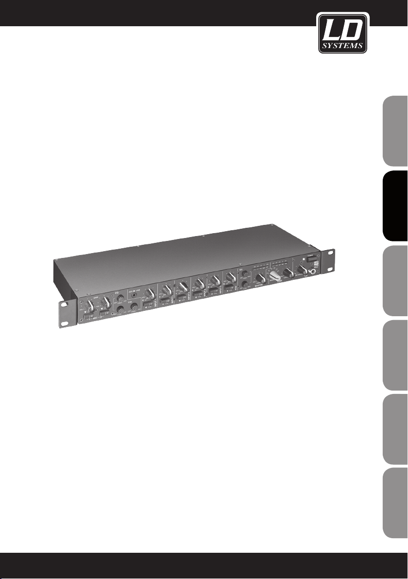
The ZONE 622 is a particularly compact 1U zone mixer with 6 line and 2 microphone channels, that can be as-
ESpAñoLpoLSKIITALIANo
signed to a stereo or a mono master output. The device has all the main features, an input for an external emergency announcement system with its own volume control and a connection to the remote mute. The ZONE 622 is
suitable as a sound system for separate areas in restaurants, clubs, hotels, fitness centres, and for presentations.
FRANCAISFRANCAIS FRANCAISFRANCAIS
2
Page 3
2-ZONE rack mixer
LDzONE622
FRANCAISFRANCAIS FRANCAISFRANCAIS
FRANCAISDEUTSCHENGLISH
ITALIANOPOLSKIESPAÑOL
3
Page 4
PREVENTIVE meaSUreS:
1. Please read these instructions carefully.
2. Keep all information and instructions in a safe place.
3. Follow the instructions.
4. Observe all safety warnings. Never remove safety warnings or other information from the equipment.
5. Use the equipment only in the intended manner and for the intended purpose.
ENGLISHDEUTSCHFRANCAIS
6. Use only sufficiently stable and compatible stands and/or mounts (for fixed installations). Make certain that wall
mounts are properly installed and secured. Make certain that the equipment is installed securely and cannot fall down.
7. During installation, observ e the applicable safety regulations for your country.
8. Never install and operate the equipment near radiators, heat registers, ovens or other sources of heat. Make
certain that the equipment is always installed so that is cooled sufficiently and cannot overheat.
9. Never place sources of ignition, e.g., burning candles, on the equipment.
10. Ventilation slits must not be blocked.
11. Do not use this equipment in the immediate vicinity of water (does not apply to special outdoor equipment in this case, observe the special instructions noted below. Do not expose this equipment to flammable materials,
fluids or gases.
12. Make certain that dripping or splashed water cannot enter the equipment. Do not place containers filled with
liquids, such as vases or drinking vessels, on the equipment.
13. Make certain that objects cannot fall into the device.
14. Use this equipment only with the accessories recommended and intended by the manufacturer.
15. Do not open or modify this equipment.
16. After connecting the equipment, check all cables in order to prevent damage or accidents, e.g., due to
tripping hazards.
17. During transport, make certain that the equipment cannot fall down and possibly cause property damage and
personal injuries.
18. If your equipment is no longer functioning properly, if fluids or objects have gotten inside the equipment or
if it has been damaged in anot her way, switch it off immediately and unplug it from the mains outlet (if it is a
powered device). This equipment may only be repaired by authorized, qualified personnel.
19. Clean the equipment using a dry cloth.
ESpAñoLpoLSKIITALIANo
20. Comply with all applicable disposal laws in your country. During disposal of packaging, please separate
plastic and paper/cardboard.
21. Plastic bags must be kept out of reach of children.
FOR EQUIPMENT THAT CONNECTS TO THE POWER MAINS:
22. CAUTION: If the power cord of the device is equipped with an earthing contact, then it must be connected to
an outlet with a protective ground. Never deactivate the protective ground of a power cord.
FRANCAISFRANCAIS FRANCAISFRANCAIS
23. If the equipment has been exposed to strong fluctuations in temperature (for example, after transport), do
not switch it on immediately. Moisture and condensation could damage the equipment. Do not switch on the
equipment until it has reached room temperature.
24. Before connecting the equipment to the power outlet, first verify that the mains voltage and frequency match
the values specified on the equipment. If the equipment has a voltage selection switch, connect the equipment to
the power outlet only if the equipment values and the mains power values match. If the included power cord or
power adapter does not fit in your wall outlet, contact your electrician.
25. Do not step on the power cord. Make certain that the power cable does not become kinked, especially at the
mains outlet and/or power adapter and the equipment connector.
26. When connecting the equipment, make certain that the power cord or power adapter is always freely
accessible. Always disconnect the equipment from the power supply if the equipment is not in use or if you want
4
Page 5
SAFETY:
to clean the equipment. Always unplug the power cord and power adapter from the power outlet at the plug or
adapter and not by pulling on the cord. Never touch the power cord and power adapter with wet hands.
27. Whenever possible, avoid switching the equipment on and off in quick succession because otherwise this
can shorten the useful life of the equipment.
28. IMPORTANT INFORMATION: Replace fuses only with fuses of the same type and rating. If a fuse blows repeatedly, please contact an authorised service centre.
29. To disconnect the equipment from the power mains completely, unplug the power cord or power adapter
from the power outlet.
30. If your device is equipped with a Volex power connector, the mating Volex equipment connector must be
unlocked before it can be removed. However, this also means that the equipment can slide and fall down if
the power cable is pulled, which can lead to personal injuries and/or other damage. For this reason, always be
careful when laying cables.
31. Unplug the power cord and power adapter from the power outlet if there is a risk of a lightning strike or
before extended periods of disuse.
FRANCAISFRANCAIS FRANCAISFRANCAIS
CAUTION
RISK OF ELECTRIC SHOCK
DO NOT OPEN
CAUTION:
Never remove the cover, because otherwise there may be a risk of electric shock. There are no user serviceable
parts inside. Have repairs carried out only by qualified service personnel.
The lightning flash with arrowhead symbol within an equilateral triangle is intended to alert the user
to the presence of uninsulated “dangerous voltage” within the product’s enclosure that may be of
sufficient magnitude to constitute a risk of electrical shock.
The exclamation mark within an equilateral triangle is intended to alert the user to the presence of
important operating and maintenance instructions.
CAUTION – HIGH VOLUME LEVELS WITH AUDIO PRODUCTS!
This equipment is intended for professional use. Therefore, commercial use of this equipment is subject to the
respectively applicable national accident prevention rules and regulations. As a manufacturer, Adam Hall is
obligated to notify you formally about the existence of potential health risks.
Hearing damage due to high volume and prolonged exposure: When in use, this product is capable of producing
high sound-pressure levels (SPL) that can lead to irreversible hearing damage in performers, employees, and
audience members. For this reason, avoid prolonged exposure to volumes in excess of 90 dB.
NOTE: For rack installation please ensure adequate ventilation above and below the unit!
FRANCAISDEUTSCHENGLISH
ITALIANOPOLSKIESPAÑOL
5
Page 6
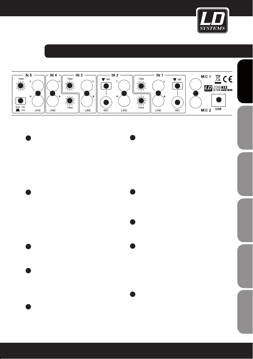
connectionS, CONTROLS, AND INDICATORS:
ENGLISHDEUTSCHFRANCAIS
1
2
3
ESpAñoLpoLSKIITALIANo
4
5
FRANCAISFRANCAIS FRANCAISFRANCAIS
2
1
3
4
6 7
5
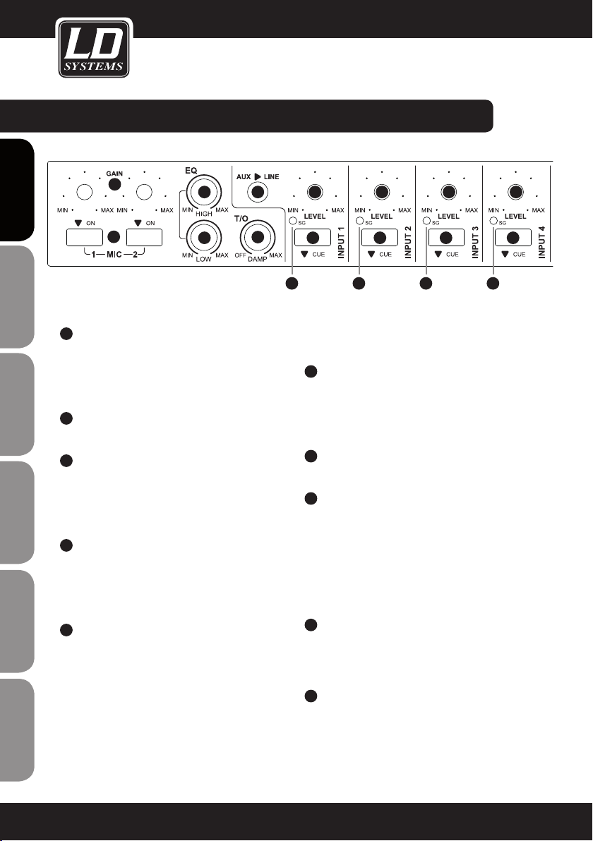
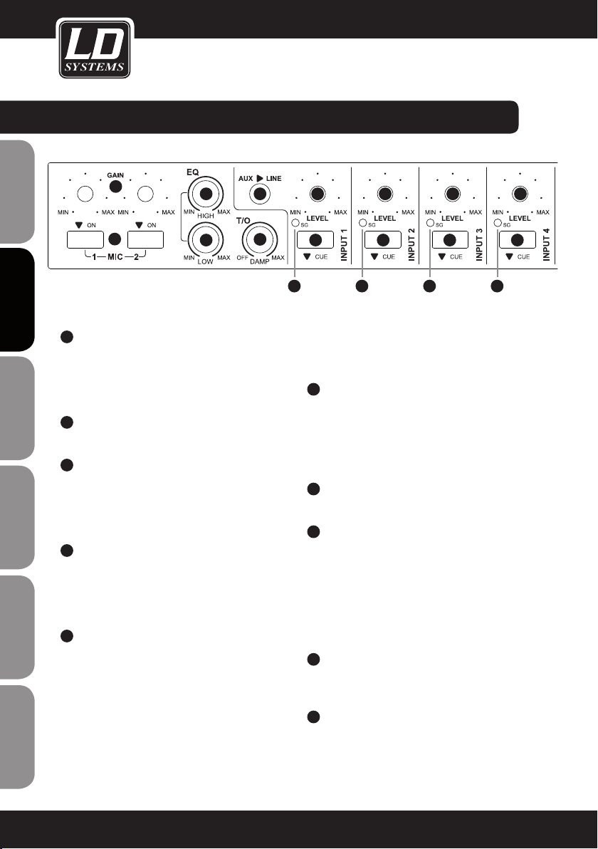
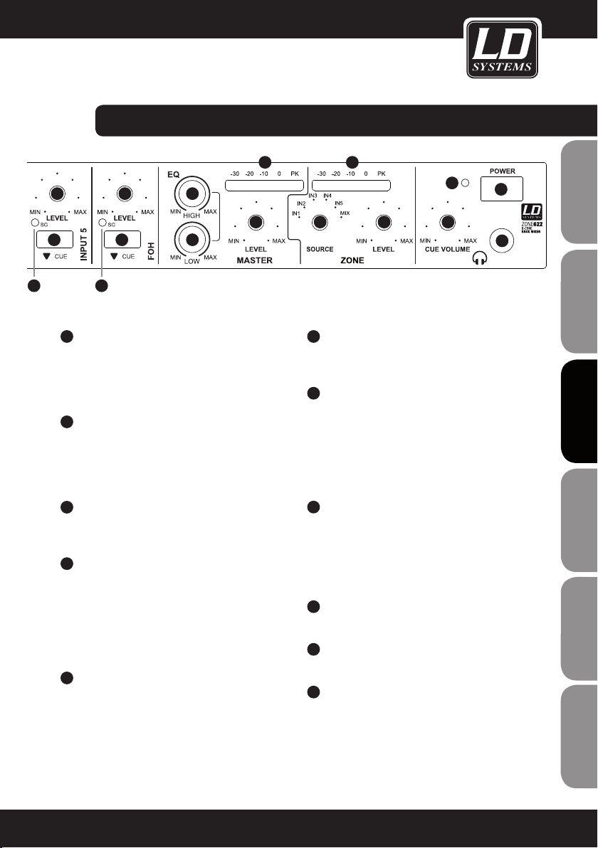
MIC 1 / 2 ON
On/Off switch for the microphone channels 1 and
2 with built-in red LED. When button is pressed,
the microphone channel is switched on and the
LED light turns on.
GAIN MIC 1 / 2
Volume control for the microphone inputs 1 and 2.
EQ HIGH MIC 1 / 2
Equalizer high band for the microphone channels 1
and 2. When turned to the left, levels are lowered,
when turned to the right, they are raised. In the centre
position (resting point), the equalizer is inactive.
EQ LOW MIC 1 / 2
Equalizer low band for microphone channels 1 and
2. When turned to the left, levels are lowered, when
turned to the right, they are raised. In the centre
position (resting point), the equalizer is inactive.
T/O DAMP
Talkover feature for microphone channels 1 and
2. If the DAMP knob is turned fully to the left, the
Talkover feature is disabled. The further the DAMP
knob is turned to the right, the stronger the signals
at the INPUT 1 - 5 will be suppressed by the
incoming microphone signal. The threshold value is
determined using the T/O LEVEL control on the rear
panel (sensitivity with which the Talkover feature
reacts to the incoming microphone signal). The
Talkover feature is not available for the ZONE output
7
8
9
8
9
7
8
9
when a signal source from INPUT 1 - 5 is selected
using the SOURCE switch.
6
AUX / LINE
Stereo line input with 3.5 mm jack and switching
function. If a 3.5 mm jack is inserted in this sokket, the RCA connectors of the INPUT 1 channel on
the rear panel of the device are turned off.
7
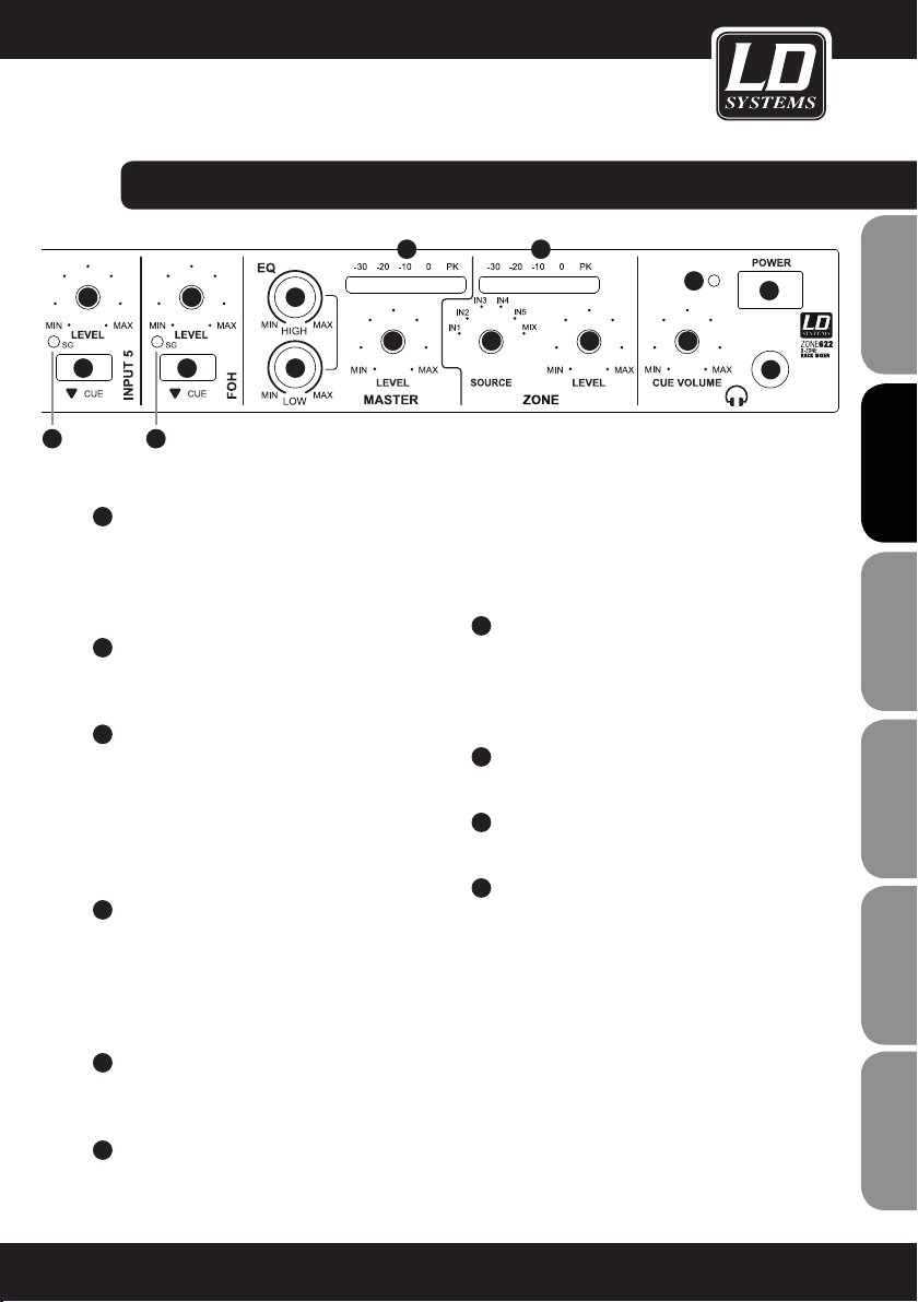
LEVEL INPUT 1 - 5 & FOH
Volume control for the channels INPUT 1 - 5 and FOH.
8
CUE INPUT 1 - 5 & FOH
Cue switch with built-in red LED for INPUT channels
1 - 5. If the switch is pressed (LED is on), the input
signal is routed to the headphone output on the
front panel of the device. The signal is sourced
before the volume control (LEVEL INPUT 1 - 5 and
FOH) of each channel, therefore it is independent of
the setting of the volume control.
9
SG LED INPUT 1 - 5 & FOH
The signal LED lights up green when an audio
signal is present at the input of the respective
channel.
10
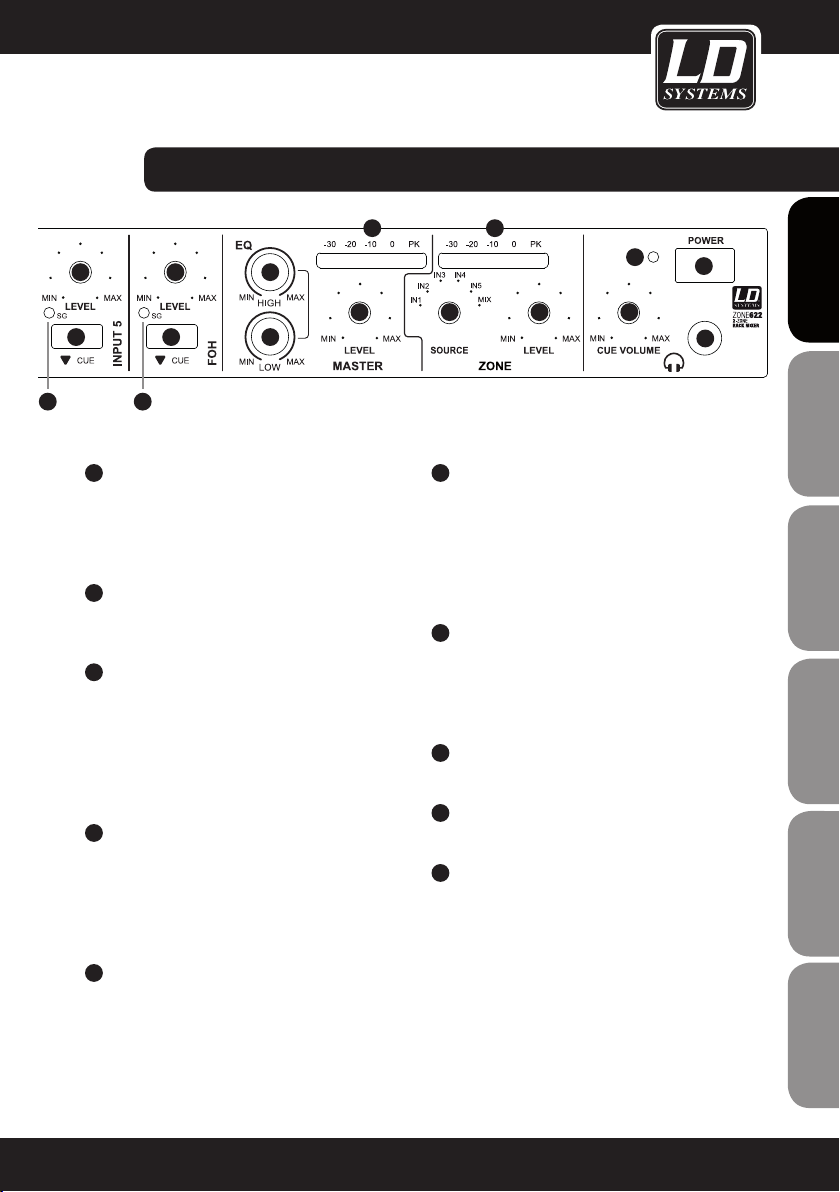
MASTER EQ HIGH
Equalizer high band for the MASTER output. When
turned to the left, levels are lowered, when turned
to the right, they are raised. In the centre position
(resting point), the equalizer is inactive.
7
8
9
6
Page 7
connectionS, CONTROLS, AND INDICATORS:
13
7
8
9
11
MASTER EQ LOW
7
8
9
10
12
11
Equalizer low band for the MASTER output. When
turned to the left, levels are lowered, when turned
to the right, they are raised. In the centre position
(resting point), the equalizer is inactive.
16
20
14
16
ZONE AUDIO LEVEL METER
15
17
Level meter display with 5 LED segments. Once
the peak LED (PK) lights up, the device is operating
at the distortion limit. It is not critical if the LED
lights briefly at peak levels for the incoming signal,
19
18
FRANCAISFRANCAIS FRANCAISFRANCAIS
FRANCAISDEUTSCHENGLISH
however continuous illumination should be avoided
12
MASTER LEVEL
by reducing the volume.
Volume control for the MASTER output on the rear
panel of the unit.
17
CUE VOLUME
Headphone volume control Channels, for which
13
MASTER AUDIO LEVEL METER
Level meter display with 5 LED segments. Once
the peak LED (PK) lights up, the device is operating
the CUE button is pressed (INPUT 1 - 5 & FOH)
can be listened to on the headphones output
regardless of their volume control setting.
at the distortion limit. It is not critical if the LED
lights briefly at peak levels for the incoming signal,
however continuous illumination should be avoided
18
HEADPHONE OUTPUT
Headphone output with 6.3 mm stereo jack.
by reducing the volume.
19
14
ZONE SOURCE
POWER
On/Off switch for the device.
Selection of the signal source to be connected to
the zone output. Alternatively, one of the 5 input
channels (IN 1 - 5), or a mix (MIX) from all input
channels (MIC 1 and 2, INPUT 1 - 5, FOH) can be
20
POWER LED
Lights up once the system is properly connected
to the power mains and switched on.
selected.
15
ZONE LEVEL
Volume control for the zone output (ZONE) on the
back of the unit.
ITALIANOPOLSKIESPAÑOL
7
Page 8
connectionS, CONTROLS, AND INDICATORS:
ENGLISHDEUTSCHFRANCAIS
21
22
ESpAñoLpoLSKIITALIANo
23
24
FRANCAISFRANCAIS FRANCAISFRANCAIS
23
21
22
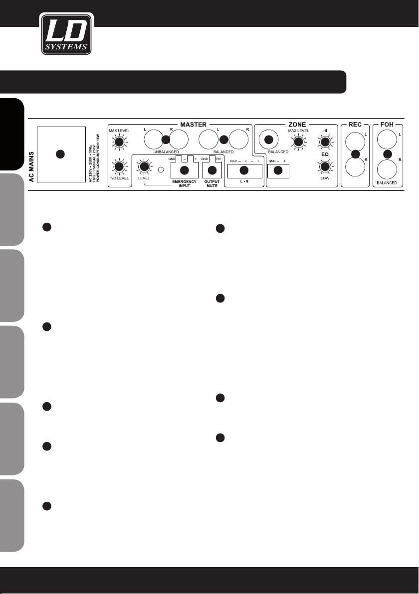
IEC POWER SOCKET WITH INTEGRATED FUSE
HOLDER
IMPORTANT INFORMATION: BEFORE using this
equipment, make certain that the mains voltage of
your energy utility and the operating voltage of the
device match! Always replace the fuse only with a
fuse of the same type with the same rating (printed
on the rear panel)! If the fuse blows repeatedly,
please contact an authorised service centre.
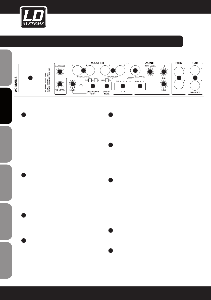
T/O LEVEL
The threshold value of the Talkover is determined
using the T/O LEVEL control (sensitivity with which
the Talkover feature reacts to the incoming microphone signal). The Talkover feature is available for
the MASTER and ZONE line outputs (SOURCE switch
set to MIX).
MASTER MAX LEVEL
Adjust the maximum volume of the MASTER
output with a suitable screwdriver.
MASTER OUTPUT L/R UNBALANCED
Unbalanced stereo output with RCA jacks (left /
right). The signal of the MASTER output consists of
the sum of the signals of the MIC 1 and 2, INPUT 1
to 5 and FOH channels.
24 25
28
30
32
33
29
2627
26
MASTER OUTPUT L/R BALANCED
Balanced stereo output (left / right) with terminal
block connector (terminal block included). The
signal of the MASTER output consists of the sum
of the signals of the MIC 1 and 2, INPUT 1 to 5 and
FOH channels.
27
EMERGENCY INPUT
Symmetrical terminal block connector for an
acoustic emergency response system (terminal
block included). As soon as an audio signal with
line-level is detected, all microphone and line
inputs are muted, and the emergency signal is
directly connected to the MASTER and ZONE line
outputs. The volume controls on the MASTER and
ZONE channels are then inactive.
28
EMERGENCY INPUT LEVEL
Adjust the volume of the emergency signal with a
suitable screwdriver.
29
OUTPUT MUTE
Terminal block connector for connecting a potential
free contact or a mute switch (terminal block
included). When the contact is closed, all input
channels are muted except for the EMERGENCY INPUT.
31
34
35 36
25
MASTER OUTPUT L/R BALANCED
Balanced stereo output with 6.3 mm jacks (left /
right). The signal of the MASTER output consists of
the sum of the signals of the MIC 1 and 2, INPUT 1
to 5 and FOH channels.
8
Page 9
connectionS, CONTROLS, AND INDICATORS:
38
37
45
30
ZONE OUTPUT BALANCED
Balanced mono output with 6.3 mm jack. The
signal from the ZONE output may be the sum of the
signals of the MIC 1 - 2 inputs and INPUT 1- 5 and
FOH (ZONE SOURCE switch 14 on the front of the
unit set on MIX), or the signal of one of the INPUTS
1 - 5 (ZONE SOURCE switch 14 on the front of the
device set to one of the INPUTS 1 - 5).
31
ZONE OUTPUT BALANCED
Balanced mono output with terminal block connection
(terminal block included). The signal from the ZONE
output may be the sum of the signals of the MIC 1 - 2
inputs and INPUT 1- 5 and FOH (ZONE SOURCE switch
14 on the front of the unit set on MIX), or the signal of
one of the INPUTS 1 - 5 (ZONE SOURCE switch 14 on
the front of the device set to one of the INPUTS 1 - 5).
32
ZONE MAX LEVEL
Adjust the maximum volume of the ZONE output
with a suitable screwdriver.
33
ZONE EQ HIGH
Equalizer high band for the ZONE output. When
turned to the left, levels are lowered, when turned
to the right, they are raised. In the centre position
(resting point), the equalizer is inactive.
34
ZONE EQ LOW
Equalizer low band for the ZONE output. When
turned to the left, levels are lowered, when turned
to the right, they are raised. In the centre position
(resting point), the equalizer is inactive.
38
38
41 42
39
40
35
REC OUTPUT L/R
Unbalanced stereo line output on RCA connectors
(left / right). The signal from the REC output consists
of the sum of the signals of the inputs MIC 1 and
2 and INPUT 1 - 5 and FOH. The output level is
independent of the setting of the volume control of
the MASTER output. The signal is sourced before the
EQ, therefore, it remains unprocessed.
36
FOH INPUT L/R
Balanced stereo line input with 6.3 mm jacks (left
/ right). Connection option for a playback device
(e.g. mixer).
37
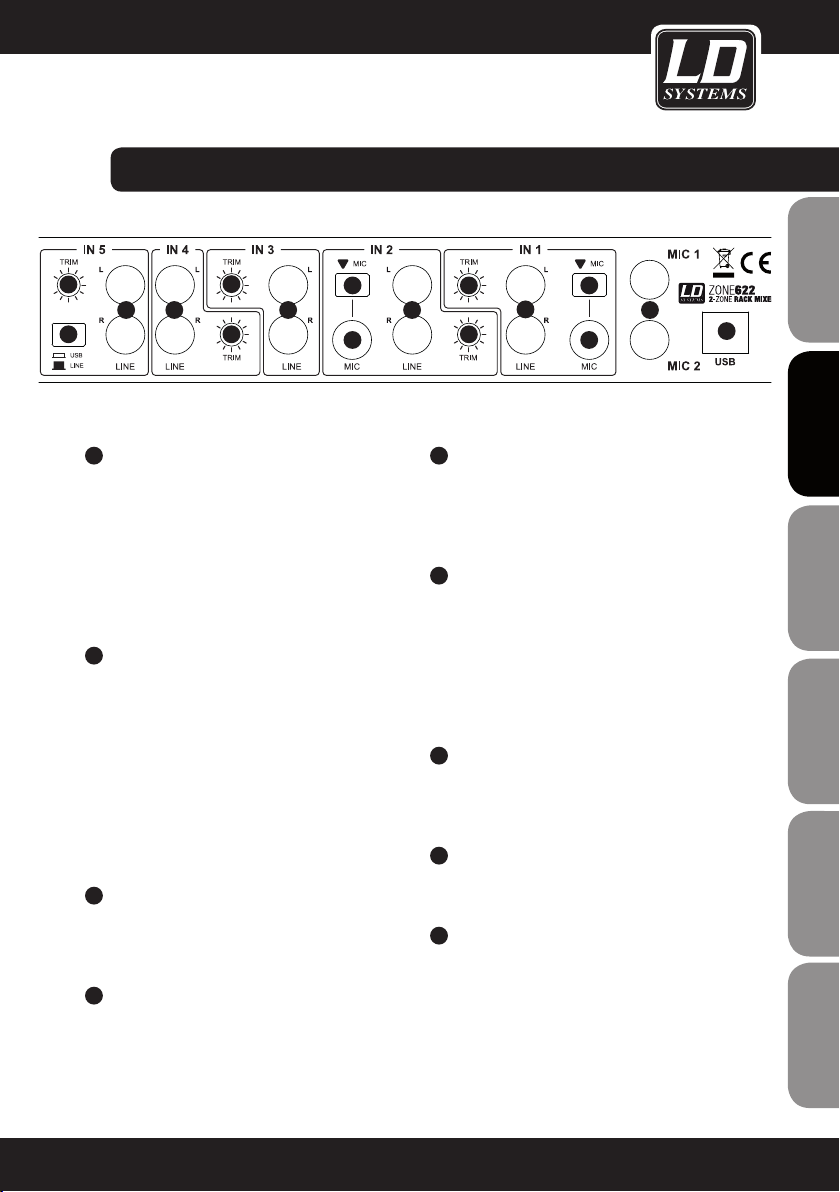
LINE IN 3 - 5
Unbalanced stereo line inputs 3 to 5 with RCA
jacks (left/right).
38
TRIM 3 - 5
To harmonise playback devices (CD player, MP3
player etc.) with different output levels, adjust the
input gain of the channels 3 - 5 with a suitable
screwdriver.
This also applies to the playback signal from the
USB-interface in channel 5.
39
LINE INPUT 1 - 2
Unbalanced stereo line inputs 1 to 2 with RCA
jacks (left/right).
41
39
42
40
4337 37
44
FRANCAISFRANCAIS FRANCAISFRANCAIS
FRANCAISDEUTSCHENGLISH
ITALIANOPOLSKIESPAÑOL
9
Page 10
connectionS, CONTROLS, AND INDICATORS:
40
ENGLISHDEUTSCHFRANCAIS
41
42
43
44
ESpAñoLpoLSKIITALIANo
FRANCAISFRANCAIS FRANCAISFRANCAIS
MIC INPUT 1 - 2
Balanced microphone inputs INPUT 1 and 2 with a
6.3 mm jack. There is no phantom power on these
microphone inputs.
MIC SWITCH INPUT 1 - 2
In pressed position, the microphone input of the
respective channel is active and the line input is
muted.
TRIM INPUT 1 - 2
Switch 41 in the released position: To harmonise
playback devices (CD player, MP3 player etc.) with
different output levels, adjust the input gain of the
channels 3 - 5 with a suitable screwdriver.
Switch 41 in the pressed position: Pre-amplification
for the microphone input. Use a suitable screwdriver
to adjust.
MIC 1 - 2
Balanced microphone inputs 1 and 2 with a 6.3
mm jack. Both microphone inputs are equipped
with a 12 V phantom power.
USB
The USB-interface (USB 1.1) allows for the mixer
to be used as an audio interface. In other words,
audio recording and playback can be done
through a connected computer with Windows
Operating System (Windows XP, Vista, 7, 8) and
Apple Macintosh OS 10.5 or higher. Separate
drivers are not necessary for the installation.
Once connected to a suitable USB port on your
computer (USB 1.1, USB 2.0), the drivers are automatically installed. The audio interface is detected
as "USB Audio CODEC" interface on both Windows
and Apple Macintosh computers.
The recording signal consists of the sum signal
which is sourced after the master level control and
the max level control, and is therefore dependent
on it. Audio playback is via the line channel INPUT
5. This requires the switch 45 on the back panel to
be pressed (USB).
45
USB / LINE
Switch for selecting the signal source for the line
channel INPUT 5. In pressed position, the USB-
interface (44) is selected, if not pressed, the line
input (37) is selected as the signal source.
10
Page 11

FRANCAISFRANCAIS FRANCAISFRANCAIS
FRANCAISDEUTSCHENGLISH
ITALIANOPOLSKIESPAÑOL
11
Page 12
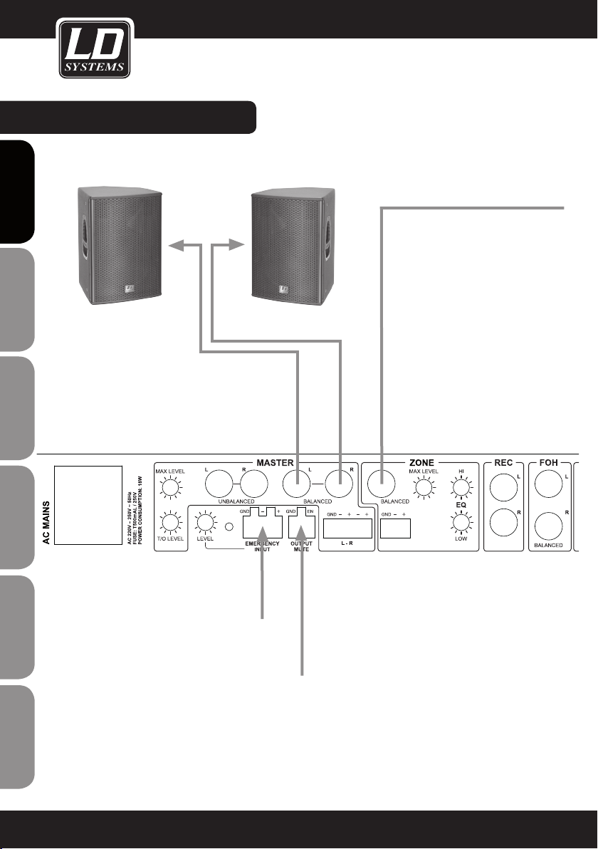
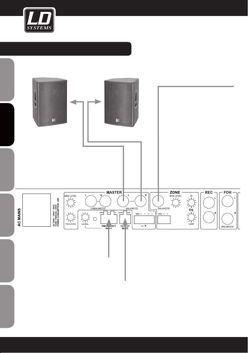
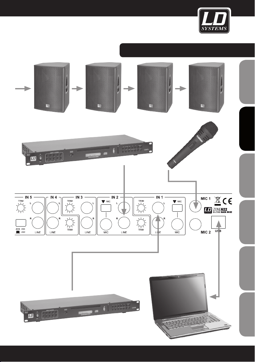
WirinG EXAMPLE:
ENGLISHDEUTSCHFRANCAIS
ESpAñoLpoLSKIITALIANo
FRANCAISFRANCAIS FRANCAISFRANCAIS
12
acoustic emergency system
potential free contact / mute switch
Page 13
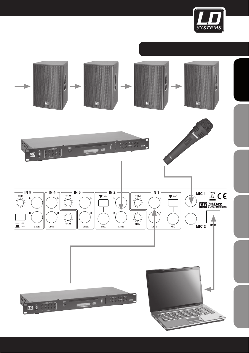
WirinG EXAMPLE:
FRANCAISFRANCAIS FRANCAISFRANCAIS
FRANCAISDEUTSCHENGLISH
ITALIANOPOLSKIESPAÑOL
13
Page 14
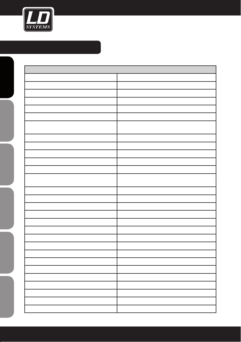
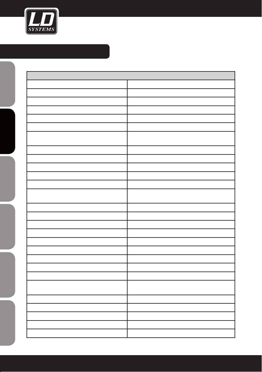
SPECIFICATIONS:
Model Name: LDZONE622
Product Type: zone mixer
ENGLISHDEUTSCHFRANCAIS
ESpAñoLpoLSKIITALIANo
FRANCAISFRANCAIS FRANCAISFRANCAIS
Type: stereo
Total Input Channels: 8 (2x Mic, 2x Mic/Line, 3x Line, 1x FOH)
Frequency Response: 20 - 40000 Hz
Microphone Channels: 2 (with phantom power 12 V)
Microphone Channels Connections: 6.3 mm jack (balanced)
Microphone Channel Controls: Gain, On/Off, 1 x EQ Hi, 1 x EQ Low, 1 x Talk Over
Microphone Channels Display Elements: On-LED
Microphone Channels Input Impedance: 4 kOhm
Microphone Channels Input Sensitivity: 6.1 mV
Microphone Channels THD: 0.08 %
Line / Microphone Channels: 2
Line / Microphone Input Connectors: 2x RCA, 6.3 mm jack (unbalanced), 3.5 mm stereo jack
Line / Microphone Channel Controls: Level, Cue, Mic/Line, Trim
LINE/MIC Channels Display Elements: Signal-LED, Cue-LED
Line Channels: 3
Line Input Connectors: 2x RCA
Line Channel Controls: Level, Cue, Trim
Line Channels Display Elements: Signal-LED, Cue-LED
Line Channel Input Impedance: 4 kOhm
Line Channels Input Sensitivity: 1.5 V
Line Channels THD: 0.03 %
Input Sensitivity AUX/Line (3.5 mm stereo jack): 3 V
FOH Channels: 1
FOH Input Connections: 2 x 6.3 mm jack balanced
FOH Input Controls: Level, Cue
FOH Input Display Elements: Signal-LED, Cue-LED
Line Outputs: 3 (Master - Stereo, Zone - Mono, Rec - Stereo)
Master Output Connectors: 2 x 6.3 mm jack balanced, 2 x RCA, terminal block
Damp, 1 x Talk Over Level
(input 1)
14
Page 15
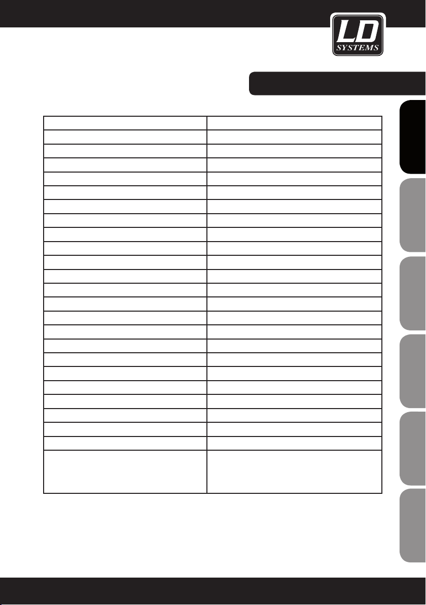
SPECIFICATIONS:
Master Controls: Level, EQ Hi, EQ Low, Max. Level
Master Display Elements: 5-segment level meter
Master Output Levels: 24 dBu (balanced), 18 dBu (unbalanced)
Zone Output Connections: 6.3 mm jack (balanced), terminal block
Zone Controls: Level, EQ Hi, EQ Low, Max. Level, Source Input 1-5/Mix
Zone Display Elements: 5-segment level meter
Zone Output Levels: 24 dBu (balanced/ unbalanced)
Output Connections Rec: 2x RCA
Headphone Output: 1
Headphone Out Port: 6.3 mm jack stereo
Headphone Output Controls: Cue Volume
Headphone Output Voltage: 1.25 V @ 32 Ohm
Additional Inputs: 2 (Emergency Input, Output Mute)
Additional Input Connections: terminal block
Additional Input Controls: level emergency input
Additional Controls: power switch
Additional Display Elements: Power-LED
Operating Voltage: 220 - 250 V AC, 50 Hz
Power Socket: IEC power socket
Power Consumption (max.): 18 W
Fuse: T 500 mAL / 250 V
Dimensions (W x H x D): 485 x 44 x 179 mm
Weight: 2.44 kg
Accessories Included: terminal blocks, power cable, operating instructions
Other Features: USB 1.1 interface (compatible with USB 2.0) for use
as an audio interface (16 Bit, recording and playback).
Supported Operating Systems: Windows XP, Vista, 7, 8,
and Apple Macintosh 10.5 or higher
FRANCAISFRANCAIS FRANCAISFRANCAIS
FRANCAISDEUTSCHENGLISH
ITALIANOPOLSKIESPAÑOL
15
Page 16
MANUFACTURER´S DecLarationS:
MANUFACTURER‘S WARRANTY
This warranty covers the Adam Hall, LD Systems, Defender, Palmer, and Cameo brands.
It applies to all products distributed by Adam Hall.
ENGLISHDEUTSCHFRANCAIS
This warranty declaration does not affect the statutory warranty claims against the manufacturer, but expands
them with additional warranty claims vis-a-vis Adam Hall.
Adam Hall warrants that the Adam Hall product that you have purchased from Adam Hall or from an Adam Hall
authorized reseller is free from defects in materials or workmanship under normal use for a period of 2 or 5 years
(please inquire on a product-by-product basis) from the date of purchase.
The warranty period begins on the date on which the product was purchased, proof of which must be produced
(through presentation of the invoice or the delivery note with the date of purchase) in the event of a warranty claim.
Should products of the brands named above be in need of repair within the limited warranty period, you are entitled
to warranty service according to the terms and conditions stated here.
During the Limited Warranty Period, Adam Hall will repair or replace the defective component parts or the product.
In the event of repair or replacement during the Limited Warranty Period, the replaced original parts and/or products become property of Adam Hall.
In the unlikely event that the product which you purchased has a recurring failure, Adam Hall has the right, at its
discretion, to replace the defective product with another product, provided that the new product is at least equivalent to the product being replaced with regard to the technical specifications.
Adam Hall does not warrant that the operation of this product will be uninterrupted or error-free. Adam Hall is not
responsible for damage that occurs as a result of your failure to follow the instructions included with the Adam Hall
branded product. The manufacturer‘s warranty does not cover – expendable parts (e. g., rechargeable batteries)
ESpAñoLpoLSKIITALIANo
- products from which the serial number has been removed or with a serial number that has been damaged as a
result of an accident - damage due to improper use, user error or other external reasons
- damage to devices operated outside the usage parameters stated in the documentation included with the product
- damage due to the use of replacement parts not manufactured, sold or recommended by Adam Hall,
- damage due to modification or servicing by anyone other than Adam Hall.
These terms and conditions constitute the complete and exclusive warranty agreement between you and Adam
Hall regarding the Adam Hall branded product you have purchased.
FRANCAISFRANCAIS FRANCAISFRANCAIS
16
Page 17
MANUFACTURER´S DecLarationS:
LIMITATION OF LIABILITY
If your Adam Hall branded hardware product fails to work as warranted above, your sole and exclusive remedy
shall be repair or replacement. Adam Halls’ maximum liability under this limited warranty is expressly limited to
the lesser of the price you have paid for the product or the cost of repair or replacement of any components that
malfunction under conditions of normal use.
Adam Hall is not liable for any damages caused by the product or the failure of the product, including any lost
profits or savings or special, incidental, or consequential damages. Adam Hall is not liable for any claim made by
a third party or made by you for a third party.
This limitation of liability applies whether damages are sought, or claims are made, under this Limited Warranty
or as a tort claim (including negligence and strict product liability), a contract claim, or any other claim, and
cannot be rescinded or changed by anyone. This limitation of liability will be effective even if you have advised
Adam Hall or an authorized representative of Adam Hall of the possibility of any such damages, but not, however,
in the event of claims for damages in connection with personal injuries.
This manufacturer‘s warranty grants you specific rights; depending on jurisdiction (nation or state), you may be
be entitled to additional claims. You are advised to consult applicable state or national laws for a full determination of your rights.
REQUESTING WARRANTY SERVICE
To request warranty service for the product, contact Adam Hall or the Adam Hall authorized reseller from which
you purchased the product.
FRANCAISFRANCAIS FRANCAISFRANCAIS
FRANCAISDEUTSCHENGLISH
EC DECLARATION oF conFormitY
The equipment marketed by Adam Hall complies (where applicable) with the essential requirements and other
relevant specifications of Directives 1999/5/EC (R&TTE), 2004/108/EC (EMC) und 2006/95/EC (LVD). Additional
information can be found at www.adamhall.com.
ITALIANOPOLSKIESPAÑOL
17
Page 18
MANUFACTURER´S DecLarationS:
PROPER DISPOSAL OF THIS PRODUCT
(Valid in the European Union and other European countries with waste separation)
This symbol on the product, or the documents accompanying the product, indicates that this appliance may not
ENGLISHDEUTSCHFRANCAIS
be treated as household waste. This is to avoid environmental damage or personal injury due to uncontrolled
waste disposal. Please dispose of this product separately from other waste and have it recycled to promote
sustainable economic activity.
Household users should contact either the retailer where they purchased this product, or their local government
office, for details on where and how they can recycle this item in an environmentally friendly manner.
Business users should contact their supplier and check the terms and conditions of the purchase contract. This
product should not be mixed with other commercial wastes for disposal .
ENVIRONMENTAL PROTECTION AND ENERGY conSerVation
Energy conservation is an active contribution to environmental protection. Please turn off all unneeded electrical
devices. To prevent unneeded devices from consuming power in standby mode, disconnect the mains plug.
ESpAñoLpoLSKIITALIANo
FRANCAISFRANCAIS FRANCAISFRANCAIS
Adam Hall GmbH, all rights reserved. The technical data and the functional product characteristics can be subject
to modifications. The photocopying, the translation, and all other forms of copying of fragments or of the integrlity
of this user’s manual is prohibited.
18
Page 19
FRANCAISFRANCAIS FRANCAISFRANCAIS
FRANCAISDEUTSCHENGLISH
ITALIANOPOLSKIESPAÑOL
19
Page 20
ENGLISHDEUTSCHFRANCAIS
Sie haben die richtige Wahl getroffen!
Dieses Gerät wurde unter hohen Qualitätsanforderungen entwickelt und gefertigt, um viele Jahre einen reibungslosen Betrieb zu gewährleisten. Dafür steht LD Systems mit seinem Namen und der langjährigen Erfahrung als
Hersteller hochwertiger Audioprodukte.
Bitte lesen Sie diese Bedienungsanleitung sorgfältig, damit Sie Ihr neues Produkt von LD Systems schnell optimal
einsetzen können.
Mehr Informationen zu LD SYSTEMS finden Sie auf unserer Internetseite WWW.LD-SYSTEMS.COM
Einführung
Der ZONE 622 ist ein besonders kompakter 1 HE Zonenmischer mit 6 Line- und 2 Mikrofonkanälen, die einem
ESpAñoLpoLSKIITALIANo
Stereo- und einem Mono-Masterausgang zugeordnet werden können. Das Gerät verfügt über alle wesentlichen
Funktionen, einen Eingang für ein externes Notfall-Durchsagesystem mit eigenem Lautstärkeregler und einen
Anschluss zum ferngesteuerten Stummschalten. Der ZONE 622 eignet sich zur Beschallung separater Zonen in
Restaurants, Clubs, Hotels, Fitnesscentern und für Präsentationen.
FRANCAISFRANCAIS FRANCAISFRANCAIS
20
Page 21
2-ZONEN rack mixer
LDzONE622
FRANCAISFRANCAIS FRANCAISFRANCAIS
FRANCAISDEUTSCHENGLISH
ITALIANOPOLSKIESPAÑOL
21
Page 22
SICHERHEITSHINWEISE:
1. Lesen Sie diese Anleitung bitte sorgfältig durch.
2. Bewahren Sie alle Informationen und Anleitungen an einem sicheren Ort auf.
3. Befolgen Sie die Anweisungen.
4. Beachten Sie alle Warnhinweise. Entfernen Sie keine Sicherheitshinweise oder andere Informationen vom Gerät.
5. Verwenden Sie das Gerät nur in der vorgesehenen Art und Weise.
ENGLISHDEUTSCHFRANCAIS
6. Verwenden Sie ausschließlich stabile und passende Stative bzw. Befestigungen (bei Festinstallationen). Stellen
Sie sicher, dass Wandhalterungen ordnungsgemäß installiert und gesichert sind. Stellen Sie sicher, dass das
Gerät sicher installiert ist und nicht herunterfallen kann.
7. Beachten Sie bei der Installation die für Ihr Land geltenden Sicherheitsvorschriften.
8. Installieren und betreiben Sie das Gerät nicht in der Nähe von Heizkörpern, Wärmespeichern, Öfen oder
sonstigen Wärmequellen. Sorgen Sie dafür, dass das Gerät immer so installiert ist, dass es ausreichend gekühlt
wird und nicht überhitzen kann.
9. Platzieren Sie keine Zündquellen wie z.B. brennende Kerzen auf dem Gerät.
10. Lüftungsschlitze dürfen nicht blockiert werden.
11. Betreiben Sie das Gerät nicht in unmittelbarer Nähe von Wasser. Bringen Sie das Gerät nicht mit brennbaren
Materialien, Flüssigkeiten oder Gasen in Berührung.
12. Sorgen Sie dafür, dass kein Tropf- oder Spritzwasser in das Gerät eindringen kann. Stellen Sie keine mit
Flüssigkeit gefüllten Behältnisse wie Vasen oder Trinkgefäße auf das Gerät.
13. Sorgen Sie dafür, dass keine Gegenstände in das Gerät fallen können.
14. Betreiben Sie das Gerät nur mit dem vom Hersteller empfohlenen und vorgesehenen Zubehör.
15. Öffnen Sie das Gerät nicht und verändern Sie es nicht.
16. Überprüfen Sie nach dem Anschluss des Geräts alle Kabelwege, um Schäden oder Unfälle, z. B. durch
Stolperfallen zu vermeiden.
17. Achten Sie beim Transport darauf, dass das Gerät nicht herunterfallen und dabei möglicherweise Sach- und
Personenschäden verursachen kann.
18. Wenn Ihr Gerät nicht mehr ordnungsgemäß funktioniert, Flüssigkeiten oder Gegenstände in das Geräteinnere
gelangt sind, oder das Gerät anderweitig beschädigt wurde, schalten Sie es sofort aus und trennen es von der
Netzsteckdose (sofern es sich um ein aktives Gerät handelt). Dieses Gerät darf nur von autorisiertem Fachperso-
ESpAñoLpoLSKIITALIANo
nal repariert werden.
19. Verwenden Sie zur Reinigung des Geräts ein trockenes Tuch.
20. Beachten Sie alle in Ihrem Land geltenden Entsorgungsgesetze. Trennen Sie bei der Entsorgung der Verpackung bitte Kunststoff und Papier bzw. Kartonagen voneinander.
21. Kunststoffbeutel müssen außer Reichweite von Kindern aufbewahrt werden.
BEI GERÄTEN MIT NETZANSCHLUSS:
FRANCAISFRANCAIS FRANCAISFRANCAIS
22. ACHTUNG: Wenn das Netzkabel des Geräts mit einem Schutzkontakt ausgestattet ist, muss es an einer
Steckdose mit Schutzleiter angeschlossen werden. Deaktivieren Sie niemals den Schutzleiter eines Netzkabels.
23. Schalten Sie das Gerät nicht sofort ein, wenn es starken Temperaturschwankungen ausgesetzt war (beispielsweise nach dem Transport). Feuchtigkeit und Kondensat könnten das Gerät beschädigen. Schalten Sie das
Gerät erst ein, wenn es Zimmertemperatur erreicht hat.
24. Bevor Sie das Gerät an die Steckdose anschließen, prüfen Sie zuerst, ob die Spannung und die Frequenz
des Stromnetzes mit den auf dem Gerät angegebenen Werten übereinstimmen. Verfügt das Gerät über einen
Spannungswahlschalter, schließen Sie das Gerät nur an die Steckdose an, wenn die Gerätewerte mit den Werten
des Stromnetzes übereinstimmen. Wenn das mitgelieferte Netzkabel bzw. der mitgelieferte Netzadapter nicht in
Ihre Netzsteckdose passt, wenden Sie sich an Ihren Elektriker.
22
Page 23
SICHERHEITSHINWEISE:
25. Treten Sie nicht auf das Netzkabel. Sorgen Sie dafür, dass spannungsführende Kabel speziell an der Netzbuchse bzw. am Netzadapter und der Gerätebuchse nicht geknickt werden.
26. Achten Sie bei der Verkabelung des Geräts immer darauf, dass das Netzkabel bzw. der Netzadapter stets frei
zugänglich ist. Trennen Sie das Gerät stets von der Stromzuführung, wenn das Gerät nicht benutzt wird, oder
Sie das Gerät reinigen möchten. Ziehen Sie Netzkabel und Netzadapter immer am Stecker bzw. am Adapter und
nicht am Kabel aus der Steckdose. Berühren Sie Netzkabel und Netzadapter niemals mit nassen Händen.
27. Schalten Sie das Gerät möglichst nicht schnell hintereinander ein und aus, da sonst die Lebensdauer des
Geräts beeinträchtigt werden könnte.
28. WICHTIGER HINWEIS: Ersetzen Sie Sicherungen ausschließlich durch Sicherungen des gleichen Typs und
Wertes. Sollte eine Sicherung wiederholt auslösen, wenden Sie sich bitte an ein autorisiertes Servicezentrum.
29. Um das Gerät vollständig vom Stromnetz zu trennen, entfernen Sie das Netzkabel bzw. den Netzadapter aus
der Steckdose.
30. Wenn Ihr Gerät mit einem verriegelbaren Netzanschluss bestückt ist, muss der passende Gerätestecker
entsperrt werden, bevor er entfernt werden kann. Das bedeutet aber auch, dass das Gerät durch ein Ziehen am
Netzkabel verrutschen und herunterfallen kann, wodurch Personen verletzt werden und/oder andere Schäden
auftreten können. Verlegen Sie Ihre Kabel daher immer sorgfältig.
31. Entfernen Sie Netzkabel und Netzadapter aus der Steckdose bei Gefahr eines Blitzschlags oder wenn Sie das
Gerät länger nicht verwenden.
CAUTION
RISK OF ELECTRIC SHOCK
DO NOT OPEN
ACHTUNG:
Entfernen Sie niemals die Abdeckung, da sonst das Risiko eines elektrischen Schlages besteht. Im Inneren des
Geräts befinden sich keine Teile, die vom Bediener repariert oder gewartet werden können. Lassen Sie Reparaturen ausschließlich von qualifiziertem Servicepersonal durchführen.
Das gleichschenkelige Dreieck mit Blitzsymbol warnt vor nichtisolierten, gefährlichen Spannungen
im Geräteinneren, die einen elektrischen Schlag verursachen können.
FRANCAISFRANCAIS FRANCAISFRANCAIS
FRANCAISDEUTSCHENGLISH
Das gleichschenkelige Dreieck mit Ausrufungszeichen kennzeichnet wichtige Bedienungs- und
Wartungshinweise.
ACHTUNG HOHE LAUTSTÄRKEN BEI AUDIOPRODUKTEN!
Dieses Gerät ist für den professionellen Einsatz vorgesehen. Der kommerzielle Betrieb dieses Geräts unterliegt
den jeweils gültigen nationalen Vorschriften und Richtlinien zur Unfallverhütung. Als Hersteller ist Adam Hall
gesetzlich verpflichtet, Sie ausdrücklich auf mögliche Gesundheitsrisiken hinzuweisen.
Gehörschäden durch hohe Lautstärken und Dauerbelastung: Bei der Verwendung dieses Produkts können
hohe Schalldruckpegel (SPL) erzeugt werden, die bei Künstlern, Mitarbeitern und Zuschauern zu irreparablen
Gehörschäden führen können. Vermeiden Sie länger anhaltende Belastung durch hohe Lautstärken über 90 dB.
HINWEIS: Bei Rackinstallation ist auf ausreichende Belüftung ober- und unterhalb des Geräts zu achten!
ITALIANOPOLSKIESPAÑOL
23
Page 24
anSchLüSSe, BEDIEN- UND ANZEIGEELEMENTE:
ENGLISHDEUTSCHFRANCAIS
1
2
3
ESpAñoLpoLSKIITALIANo
4
5
FRANCAISFRANCAIS FRANCAISFRANCAIS
2
1
3
4
6 7
5
MIC 1 / 2 ON
Ein- / Ausschalter für die Mikrofonkanäle 1 und 2 mit
integrierter roter LED. In heruntergedrückter Position
ist der Mikrofonkanal eingeschaltet und die LED
leuchtet.
GAIN MIC 1 / 2
Lautstärkeregler für die Mikrofonkanäle 1 und 2.
EQ HIGH MIC 1 / 2
Equalizer Höhenband für Mikrofonkanäle 1 und
2. Nach links gedreht werden Höhen abgesenkt,
nach rechts gedreht angehoben. In Mittelstellung
(Rastpunkt) ist der Equalizer inaktiv.
EQ LOW MIC 1 / 2
Equalizer Bassband für Mikrofonkanäle 1 und 2.
Nach links gedreht werden Bässe abgesenkt, nach
rechts gedreht angehoben. In Mittelstellung (Rastpunkt) ist der Equalizer inaktiv.
T/O DAMP
Talkover Funktion für Mikrofonkanäle 1 und 2.
DAMP-Regler vollständig nach links gedreht
deaktiviert die Talkover Funktion. Je weiter der
DAMP-Regler nach rechts gedreht wird, um so
stärker werden die Signale, die an den Eingängen
INPUT 1 - 5 und FOH anliegen durch das eingehende
Mikrofonsignal unterdrückt. Der Schwellenwert wird
mit Hilfe des T/O LEVEL-Reglers auf der Rückseite
eingestellt (Empfindlichkeit, mit der die Talkover
Funktion auf das eingehende Mikrofonsignal
7
8
9
8
9
7
8
9
9
reagiert). Die Talkover Funktion ist für den ZONE-Ausgang
nicht verfügbar, wenn mittels des SOURCE-Schalters eine
der Signalquellen INPUT 1 - 5 ausgewählt ist.
6
AUX / LINE
Stereo-Line-Eingang mit 3,5 mm Klinkenbuchse und
Schaltfunktion. Wird ein 3,5 mm Klinkenstecker mit
dieser Buchse verbunden, werden die Cinch-Eingänge
des Kanals INPUT 1 auf der Rückseite des Geräts
abgeschaltet.
7
LEVEL INPUT 1 - 5 & FOH
Lautstärkeregler für die Kanäle INPUT 1 - 5 und FOH.
8
CUE INPUT 1 - 5 & FOH
Cue-Schalter mit integrierter LED für die Kanäle INPUT
1 - 5. Das anliegende Signal wird bei herunterge-
drücktem Schalter (LED leuchtet) auf den Kopfhörer-
ausgang auf der Vorderseite des Geräts gelegt. Das
Signal wird vor dem Lautstärkeregler (LEVEL INPUT 1 -
5 und FOH) des jeweiligen Kanals abgegriffen, ist also
unabhängig von der Einstellung des Lautstärkereglers.
9
SG LED INPUT 1 - 5 & FOH
Die Signal-LED leuchtet grün auf, sobald ein Audio-
signal am Eingang des jeweiligen Kanals anliegt.
10
MASTER EQ HIGH
Equalizer Höhenband für den MASTER-Ausgang. Nach
links gedreht werden Höhen abgesenkt, nach rechts
gedreht angehoben. In Mittelstellung (Rastpunkt) ist
der Equalizer inaktiv.
7
8
24
Page 25
anSchLüSSe, BEDIEN- UND ANZEIGEELEMENTE:
13
7
8
9
11
MASTER EQ LOW
7
8
9
10
12
11
Equalizer Bassband für den MASTER-Ausgang.
Nach links gedreht werden Bässe abgesenkt,
nach rechts gedreht angehoben. In Mittelstellung
(Rastpunkt) ist der Equalizer inaktiv.
12
MASTER LEVEL
Lautstärkeregler für den MASTER-Ausgang auf der
Rückseite des Geräts.
16
20
14
5
Verzerrungsgrenze betrieben. Kurzes Aufleuchten bei
15
17
19
Pegelspitzen im anliegenden Signal ist dabei
unkritisch, dauerhaftes Leuchten sollte durch
Reduzierung der Lautstärke vermieden werden.
17
CUE VOLUME
Lautstärkeregler für den Kopfhörerausgang. Kanäle,
deren CUE-Knopf gedrückt wird (INPUT 1 - 5 & FOH),
können unabhängig von der Einstellung ihrer Laut-
18
FRANCAISFRANCAIS FRANCAISFRANCAIS
FRANCAISDEUTSCHENGLISH
stärkeregler am Kopfhörerausgang abgehört werden.
13
MASTER AUDIO LEVEL METER
Level Meter Anzeige mit 5 LED Segmenten. Sobald
die Peak-LED (PK) aufleuchtet wird das Gerät an der
18
KOPFHÖRERAUSGANG
Kopfhörerausgang mit 6,3 mm Stereo Klinkenbuchse.
Verzerrungsgrenze betrieben. Kurzes Aufleuchten
bei Pegelspitzen im anliegenden Signal ist dabei unkritisch, dauerhaftes Leuchten sollte durch
19
POWER
Ein- / Ausschalter für das Gerät.
Reduzierung der Lautstärke vermieden werden.
20
14
ZONE SOURCE
Auswahl der Signalquelle, die auf den Zonen-Ausgang
POWER LED
Leuchtet auf, sobald das Gerät korrekt am Stromnetz
angeschlossen und eingeschaltet ist.
geschaltet werden soll. Alternativ kann einer der 5
Input-Kanäle (IN 1 - 5), oder ein Mix (MIX) aus allen
Eingangskanälen (MIC 1 und 2, INPUT 1 - 5, FOH)
ausgewählt werden.
15
ZONE LEVEL
Lautstärkeregler für den Zonen-Ausgang (ZONE) auf
der Rückseite des Geräts.
16
ZONE AUDIO LEVEL METER
Level Meter Anzeige mit 5 LED Segmenten. Sobald
die Peak-LED (PK) aufleuchtet wird das Gerät an der
ITALIANOPOLSKIESPAÑOL
25
Page 26
anSchLüSSe, BEDIEN- UND ANZEIGEELEMENTE:
ENGLISHDEUTSCHFRANCAIS
21
22
ESpAñoLpoLSKIITALIANo
23
FRANCAISFRANCAIS FRANCAISFRANCAIS
24
23
21
22
IEC NETZBUCHSE MIT INTEGRIERTEM
SICHERUNGSHALTER
WICHTIGE HINWEISE: Stellen Sie VOR Inbetriebnahme sicher, dass die Netzspannung Ihres
Energieversorgers und die Betriebsspannung
des Geräts übereinstimmen! Ersetzen Sie die
Sicherung ausschließlich durch eine Sicherung
des gleichen Typs und mit gleichen Werten (siehe
Aufdruck auf der Rückseite)! Sollte die Sicherung
wiederholt auslösen, wenden Sie sich bitte an ein
autorisiertes Servicezentrum.
T/O LEVEL
Der Talkover-Schwellenwert wird mit Hilfe des
T/O LEVEL-Reglers eingestellt (Empfindlichkeit,
mit der die Talkover Funktion auf das anliegende
Mikrofonsignal reagiert). Die Talkover Funktion
ist verfügbar für die Line-Ausgänge MASTER und
ZONE (SOURCE-Schalter in Position MIX).
MASTER MAX LEVEL
Stellen Sie mit Hilfe eines geeigneten Schraubendrehers den maximalen Pegel ein, der am MASTERAusgang anliegen soll.
MASTER OUTPUT L/R UNBALANCED
Unsymmetrischer Stereo-Ausgang mit CinchBuchsen (links / rechts). Das Signal des MASTERAusgangs besteht aus der Summe der Signale der
Eingänge MIC 1 und 2, INPUT 1 bis 5 und FOH.
24 25
28
30
32
33
29
2627
25
MASTER OUTPUT L/R BALANCED
Symmetrischer Stereo-Ausgang mit 6,3 mm Klinken-
buchsen (links / rechts). Das Signal des MASTER-
Ausgangs besteht aus der Summe der Signale der
Eingänge MIC 1 und 2, INPUT 1 bis 5 und FOH.
26
MASTER OUTPUT L/R BALANCED
Symmetrischer Stereo-Ausgang (links / rechts) mit
Klemmblock-Anschluss (Klemmblock im Lieferum-
fang). Das Signal des MASTER-Ausgangs besteht aus
der Summe der Signale der Eingänge MIC 1 und 2,
INPUT 1 bis 5 und FOH.
27
EMERGENCY INPUT
Symmetrischer Klemmblock-Anschluss für ein
akustisches Notfall-System (Klemmblock im
Lieferumfang). Sobald ein Audiosignal mit Line-Pegel
anliegt, werden alle Mikrofon- und Line-Eingänge
stumm geschaltet und das Notfallsignal direkt auf
die Line-Ausgänge MASTER und ZONE geschaltet.
Die Lautstärkeregler des MASTER- und ZONE-Kanals
sind jetzt inaktiv.
28
EMERGENCY INPUT LEVEL
Stellen Sie mit Hilfe eines geeigneten Schrauben-
drehers die Lautstärke des Notfall-Signals ein.
29
OUTPUT MUTE
Klemmblock-Anschluss zum Anschließen eines
potentialfreien Kontakts oder eines Mute-Schalters
(Klemmblock im Lieferumfang). Bei geschlossenem
Kontakt werden alle Eingangskanäle außer dem
EMERGENCY INPUT stumm geschaltet.
31
34
35 36
26
Page 27
anSchLüSSe, BEDIEN- UND ANZEIGEELEMENTE:
38
37
45
30
ZONE OUTPUT BALANCED
Symmetrischer Mono-Ausgang mit 6,3 mm Klinkenbuchse. Das Signal des ZONE-Ausgangs kann aus der
Summe der Signale der Eingänge MIC 1 und 2, INPUT
1 bis 5 und FOH bestehen (ZONE SOURCE-Schalter 14
auf der Vorderseite des Geräts auf MIX stellen), oder
das Signal einer der Eingänge INPUT 1 bis 5 enthalten
(ZONE SOURCE-Schalter 14 auf der Vorderseite des
Geräts auf einen der Eingänge INPUT 1 - 5 stellen).
31
ZONE OUTPUT BALANCED
Symmetrischer Mono-Ausgang mit KlemmblockAnschluss (Klemmblock im Lieferumfang). Das
Signal des ZONE-Ausgangs kann aus der Summe
der Signale der Eingänge MIC 1 und 2, INPUT 1
bis 5 und FOH bestehen (ZONE SOURCE-Schalter
14 auf der Vorderseite des Geräts auf MIX stellen),
oder das Signal einer der Eingänge INPUT 1 bis
5 enthalten (ZONE SOURCE-Schalter 14 auf der Vorderseite des Geräts auf einen der Eingänge INPUT
1 - 5 stellen).
32
ZONE MAX LEVEL
Stellen Sie mit Hilfe eines geeigneten Schraubendrehers den maximalen Pegel ein, der am ZONEAusgang anliegen soll.
33
ZONE EQ HIGH
Equalizer Höhenband für den ZONE-Ausgang. Nach
links gedreht werden Höhen abgesenkt, nach rechts
gedreht angehoben. In Mittelstellung (Rastpunkt) ist der
Equalizer inaktiv.
38
38
41 42
39
40
34
ZONE EQ LOW
Equalizer Bassband für ZONE-Ausgang. Nach links
gedreht werden Bässe abgesenkt, nach rechts gedreht
angehoben. In Mittelstellung (Rastpunkt) ist der
Equalizer inaktiv.
35
REC OUTPUT L/R
Unsymmetrischer Stereo-Line-Ausgang mit CinchBuchsen (links / rechts). Das Signal des REC-Ausgangs
besteht aus der Summe der Signale der Eingänge MIC
1 und 2, INPUT 1 - 5 und FOH. Der Ausgangspegel ist
abhängig von der Einstellung des Lautstärkereglers
des MASTER-Ausgangs, das Signal wird vor dem
Equalizer abgegriffen, bleibt davon also unbearbeitet.
36
FOH INPUT L/R
Symmetrischer Stereo-Line-Eingang mit 6,3 mm
Klinkenbuchsen (links / rechts). Anschlussmöglichkeit
für ein Zuspielgerät (z.B. Mischpult).
37
LINE IN 3 - 5
Unsymmetrische Stereo-Line-Eingänge 3 bis 5 mit
Cinch-Buchsen (links / rechts).
38
TRIM 3 - 5
Um Zuspielgeräte (CD-Player, MP3-Player o.ä.) mit
unterschiedlichem Ausgangspegel anzugleichen,
stellen Sie die Vorverstärkung der Kanäle 3 bis 5 mit
Hilfe eines geeigneten Schraubendrehers ein.
In Kanal 5 ebenso für das Wiedergabesignal der USBSchnittstelle zutreffend.
41
39
42
40
4337 37
44
FRANCAISFRANCAIS FRANCAISFRANCAIS
FRANCAISDEUTSCHENGLISH
ITALIANOPOLSKIESPAÑOL
27
Page 28
anSchLüSSe, BEDIEN- UND ANZEIGEELEMENTE:
39
ENGLISHDEUTSCHFRANCAIS
40
41
42
43
ESpAñoLpoLSKIITALIANo
LINE INPUT 1 - 2
Unsymmetrische Stereo-Line-Eingänge 1 und 2 mit
Cinch-Buchsen (links / rechts).
MIC INPUT 1 - 2
Symmetrische Mikrofoneingänge INPUT 1 und 2 mit
6,3 mm Klinkenbuchse. An diesen Mikrofoneingängen
liegt keine Phantomspeisung an.
MIC SCHALTER INPUT 1 - 2
In heruntergedrückter Position ist der Mikrofoneingang des jeweiligen Kanals aktiv und der LineEingang stumm geschaltet.
TRIM INPUT 1 - 2
Schalter 41 in nicht gedrückter Position: Um
Zuspielgeräte (CD-Player, MP3-Player o.ä.) mit
unterschiedlichem Ausgangspegel anzugleichen,
stellen Sie die Vorverstärkung der Kanäle 3 bis 5
mit Hilfe eines geeigneten Schraubendrehers ein.
Schalter 41 in gedrückter Position: Vorverstärkung für
den Mikrofoneingang. Verwenden Sie zum Einstellen
einen geeigneten Schraubendreher.
MIC 1 - 2
Symmetrische Mikrofoneingänge 1 und 2 mit 6,3 mm
Klinkenbuchse. Beide Mikrofoneingänge verfügen über
eine 12 V Phantomspeisung.
und wird hinter dem Master Level Regler und dem Max
Level Regler abgegriffen, ist also abhängig davon. Die
Audio-Wiedergabe erfolgt über den Line-Kanal INPUT 5.
Hierfür muss der Schalter 45 auf der Rückseite heruntergedrückt sein (USB).
45
USB / LINE
Schalter für die Wahl der Signalquelle für den Line-
Kanal INPUT 5. In heruntergedrückter Position ist die
USB-Schnittstelle (44), in nicht heruntergedrückter
Position der Line-Eingang (37) als Signalquelle
ausgewählt.
44
FRANCAISFRANCAIS FRANCAISFRANCAIS
28
USB
Die USB-Schnittstelle (USB 1.1) ermöglicht es, das
Mischpult als Audio-Interface zu nutzen. Das heißt,
Audio-Aufnahme und -Wiedergabe können über
einen angeschlossenen Computer mit Windows
Betriebsystem (Windows XP, Vista, 7, 8) und Apple
Macintosh Betriebsystem ab 10.5 erfolgen. Separate
Treiber sind für die Installation nicht notwendig. Nach
dem Anschließen an eine geeignete USB-Schnittstelle
des Computers (USB 1.1, USB 2.0) werden die Treiber
automatisch installiert und das Audio-Interface wird
als „USB Audio CODEC“ Interface sowohl auf Windows
als auch auf Apple Macintosh Computern erkannt.
Das Aufnahmesignal besteht aus dem Summensignal
Page 29

FRANCAISFRANCAIS FRANCAISFRANCAIS
FRANCAISDEUTSCHENGLISH
ITALIANOPOLSKIESPAÑOL
29
Page 30
VerkaBeLUnGSBEISPIEL:
ENGLISHDEUTSCHFRANCAIS
ESpAñoLpoLSKIITALIANo
FRANCAISFRANCAIS FRANCAISFRANCAIS
30
akustisches Notfall-System
potentialfreier Kontakt / Mute-Schalter
Page 31
VerkaBeLUnGSBEISPIEL:
FRANCAISFRANCAIS FRANCAISFRANCAIS
FRANCAISDEUTSCHENGLISH
ITALIANOPOLSKIESPAÑOL
31
Page 32
SPEZIFIKATIONEN:
Modellbezeichnung: LDZONE622
Produktart: Zonen-Mixer
ENGLISHDEUTSCHFRANCAIS
ESpAñoLpoLSKIITALIANo
FRANCAISFRANCAIS FRANCAISFRANCAIS
Typ: Stereo
Eingangskanäle gesamt: 8 (2x Mic, 2x Mic/Line, 3x Line, 1x FOH)
Frequenzgang: 20 - 40000 Hz
Mikrofonkanäle: 2, mit Phantom Power 12 V
Anschlüsse Mikrofonkanäle: 6,3 mm Klinke (symmetrisch)
Bedienelemente Mikrofonkanäle: Gain, On/Off, 1 x EQ Hi, 1 x EQ Low, 1 x Talk Over
Anzeigeelemente Mikrofonkanäle: On-LED
Eingangsimpedanz Mikrofonkanäle: 4 kOhm
Eingangsempfindlichkeit Mikrofonkanäle: 6,1 mV
THD Mikrofonkanäle: 0,08 %
Line- / Mikrofon-Kanäle: 2
Line- / Mikrofon-Eingangsanschlüsse: 2 x Cinch, 6,3 mm Klinke (unsymmetrisch), 3,5 mm
Bedienelemente Line- / Mikrofon-Kanäle: Level, Cue, Mic/Line, Trim
Anzeigeelemente Line- / Mikrofonkanäle: Signal-LED, Cue-LED
Line-Kanäle: 3
Line-Eingangsanschlüsse: 2 x Cinch
Bedienelemente Line-Kanäle: Level, Cue, Trim
Anzeigeelemente Line-Kanäle: Signal-LED, Cue-LED
Eingangsimpedanz Line-Kanäle: 4 kOhm
Eingangsempfindlichkeit Line-Kanäle: 1,5 V
THD Line-Kanäle: 0,03 %
Eingangsempfindlichkeit AUX/Line (3,5 mm Stereo
Klinke):
FOH-Kanäle: 1
Anschlüsse FOH-Eingang: 2 x 6,3 mm Klinke symmetrisch
Bedienelemente FOH-Kanäle: Level, Cue
Anzeigeelemente FOH-Kanäle: Signal-LED, Cue-LED
Line-Ausgänge: 3 (Master - Stereo, Zone - Mono, Rec - Stereo)
Damp, 1 x Talk Over Level
Stereo Klinke (Input 1)
3 V
32
Page 33

SPEZIFIKATIONEN:
Ausgangsanschlüsse Master: 2 x 6,3 mm Klinke symmetrisch, 2 x Cinch, Klemm-
block
Bedienelemente Master: Level, EQ Hi, EQ Low, Max. Level
Anzeigeelemente Master: 5-Segment Level Meter
Ausgangspegel Master: 24 dBu (symmetrisch), 18 dBu (unsymmetrisch)
Ausgangsanschlüsse Zone: 6,3 mm Klinke symmetrisch, Klemmblock
Bedienelemente Zone: Level, EQ Hi, EQ Low, Max. Level, Source Input 1-5/Mix
Anzeigeelemente Zone: 5-Segment Level Meter
Ausgangspegel Zone: 24 dBu (symmetr./ unsymmetr.)
Ausgangsanschlüsse Rec: 2 x Cinch
Kopfhörer-Ausgang: 1
Anschluss Kopfhörerausgang: 6,3 mm Klinke Stereo
Bedienelemente Kopfhörerausgang: Cue Volume
Ausgangsspannung Kopfhörerausgang: 1,25 V @ 32 Ohm
Zusätzliche Eingänge: 2 (Emergency Input, Output Mute)
Anschlüsse zusätzliche Eingänge: Klemmblock
Bedienelemente zusätzliche Eingänge: Level Emergency Input
Zusätzliche Bedienelemente: Power-Schalter
Zusätzliche Anzeigeelemente: Power-LED
Betriebsspannung: 220 - 250 V AC, 50 Hz
Netzanschluss: IEC Gerätebuchse
Leistungsaufnahme (max.): 18 W
Sicherung: T 500 mAL / 250 V
Abmessungen (B x H x T): 485 x 44 x 179 mm
Gewicht: 2,44 kg
Zubehör inklusive: Klemmblöcke, Netzkabel, Anleitung
Weitere Eigenschaften: USB 1.1 Schnittstelle (kompatibel mit USB 2.0) für
den Einsatz als Audio-Interface (16 Bit, Aufnahme und
Wiedergabe). Unterstützte Betriebssysteme: Windows
XP, Vista, 7, 8 und Apple Macintosh ab 10.5
FRANCAISFRANCAIS FRANCAISFRANCAIS
FRANCAISDEUTSCHENGLISH
ITALIANOPOLSKIESPAÑOL
33
Page 34

HERSTELLERERKLÄRUNGEN:
GARANTIEBESTIMMUNGEN
Diese Garantie erstreckt sich auf die Marken Adam Hall, LD Systems, Defender, Palmer und Cameo.
Sie gilt für alle Produkte im Vertrieb von Adam Hall.
ENGLISHDEUTSCHFRANCAIS
Diese Garantieerklärung berührt nicht die gesetzlichen Gewährleistungsansprüche an den Hersteller, sondern erweitert diese um zusätzliche Garantieansprüche gegenüber der Firma Adam Hall.
Adam Hall garantiert für den Zeitraum von zwei beziehungsweise fünf Jahren (bitte produktspezifisch erfragen) ab
Kaufdatum, dass dieses Adam Hall-Produkt, welches Sie direkt über Adam Hall oder einen von Adam Hall autorisierten Händler erworben haben, bei bestimmungsgemäßem Gebrauch frei von Material- und Fertigungsfehlern ist.
Der Garantiezeitraum beginnt mit dem Kaufdatum des Produkts, das im Garantiefall entsprechend nachzuweisen
ist (durch Vorlegen der Rechnung oder des Lieferscheins mit dem Kaufdatum). Sollte bei Produkten der oben genannten Marken innerhalb der Garantiezeit eine Reparatur erforderlich sein, sind Sie berechtigt, diese zu den hier
aufgeführten Bedingungen durchführen zu lassen.
Innerhalb des Garantiezeitraums übernimmt Adam Hall die Reparatur oder den Ersatz der defekten Komponente(n)
bzw. des Produkts. Im Falle einer Reparatur bzw. eines Austauschs innerhalb des Garantiezeitraumes gehen ausgewechselte Originalteile bzw. Produkte in das Eigentum der Firma Adam Hall über.
Sollte der unwahrscheinliche Fall eintreten, dass bei dem von Ihnen erworbenen Produkt ein Fehler wiederholt
auftritt, hat die Firma Adam Hall das Recht, das defekte Produkt nach eigenem Ermessen durch ein anderes
Produkt zu ersetzen, sofern das neue dem ausgetauschten Produkt in Bezug auf die technischen Spezifikationen
mindestens gleichwertig ist.
Adam Hall übernimmt keine Garantie für einen störungs- und/oder fehlerfreien Betrieb dieses Produkts. Auch für
Schäden durch Nichtbeachtung der diesem Adam Hall-Produkt beiliegenden Bedienungsanleitung und anderen
ESpAñoLpoLSKIITALIANo
Unterlagen ist Adam Hall nicht verantwortlich. Die Herstellergarantie gilt nicht - für Verschleißteile (z. B. Akkus) - für
Produkte, von denen die Seriennummer entfernt wurde oder die aufgrund eines Unfalls beschädigt wurden - für
Schäden durch unsachgemäßen Betrieb, durch Fehlbedienung oder andere externe Gründe
- für Schäden an Geräten, die nicht entsprechend den Betriebsparametern betrieben wurden (Parameter gemäß
den im Lieferumfang enthaltenen Unterlagen),
- für Schäden durch die Verwendung nicht von Adam Hall hergestellter, vertriebener oder empfohlener Ersatzteile,
- für Schäden durch Fremdeingriffe/Modifikationen oder nicht durch Adam Hall durchgeführte Reparaturen.
FRANCAISFRANCAIS FRANCAISFRANCAIS
Diese Bestimmungen und Bedingungen stellen die vollständige und ausschließliche Garantievereinbarung zwischen Ihnen und Adam Hall für das von Ihnen erworbene Adam Hall-Produkt dar.
34
Page 35

HERSTELLERERKLÄRUNGEN:
HAFTUNGSBESCHRÄNKUNG
Falls an Hardware-Produkten von Adam Hall innerhalb der Garantiezeit Material- oder Verarbeitungsfehler
(gemäß der Garantieerklärung oben) auftreten, besteht Ihr alleiniger und ausschließlicher Anspruch aus dieser
Garantie in der Reparatur oder dem Austausch des Geräts. Die maximale Haftung der Firma Adam Hall ist entsprechend dieser Garantie ausdrücklich auf den Kaufpreis oder die Kosten für eine Reparatur oder Ersatz – und
zwar den jeweils niedrigeren Betrag – der bei üblichem Gebrauch fehlerhaften Komponenten begrenzt.
Adam Hall ist nicht haftbar für jegliche durch das Produkt oder das Versagen des Produkts verursachte Schäden,
einschließlich Gewinneinbußen und unterbliebener Einsparungen sowie besonderer, indirekter oder Folgeschäden. Des Weiteren ist Adam Hall nicht haftbar gegenüber Rechtsansprüchen Dritter oder durch Sie im Namen
Dritter angemeldeten Forderungen.
Diese Haftungsbeschränkung gilt unabhängig davon, ob Schäden gerichtlich verfolgt oder Schadensersatzansprüche im Rahmen dieser Garantie oder aufgrund unerlaubter Handlungen (einschließlich Fahrlässigkeit
und Gefährdungshaftung) oder aufgrund vertraglicher oder sonstiger Ansprüche gestellt werden, und kann von
niemandem aufgehoben oder verändert werden. Diese Haftungsbeschränkung ist auch dann gültig, wenn Sie die
Firma Adam Hall oder einen autorisierten Vertreter von Adam Hall auf die Möglichkeit solcher Schäden aufmerksam gemacht haben, nicht jedoch bei Schadensersatzansprüchen in Zusammenhang mit Personenschäden.
Diese Herstellergarantie räumt Ihnen bestimmte Rechte ein; je nach Gerichtsbarkeit (Staat oder Land) stehen
Ihnen möglicherweise weitere Ansprüche zu. Es ist ratsam, in solchen Fällen die entsprechenden Gesetze heranzuziehen, um Ihre Rechte umfassend zu ermitteln.
INANSPRUCHNAHME DER GARANTIE
Wenden Sie sich im Garantiefall direkt an Adam Hall oder den von Adam Hall autorisierten Händler, bei dem Sie
das Produkt erworben haben.
FRANCAISFRANCAIS FRANCAISFRANCAIS
FRANCAISDEUTSCHENGLISH
EG-KONFORMITÄTSerkLÄrUnG
Die von Adam Hall vertriebenen Geräte entsprechen (soweit zutreffend) den grundlegenden Anforderungen und
weiteren relevanten Spezifikationen der Richtlinien 1999/5/EC (R&TTE), 2004/108/EC (EMC) und 2006/95/EC
(LVD). Weitere Informationen finden Sie unter www.adamhall.com.
ITALIANOPOLSKIESPAÑOL
35
Page 36

HERSTELLERERKLÄRUNGEN:
KORREKTE ENTSORGUNG DIESES PRODUKTES
(Gültig in der Europäischen Union und anderen europäischen Ländern mit Mülltrennung)
Dieses Symbol auf dem Produkt oder dazugehörigen Dokumenten weist darauf hin, dass das Gerät am Ende der
ENGLISHDEUTSCHFRANCAIS
Produktlebenszeit nicht zusammen mit dem normalen Hausmüll entsorgt werden darf, um Umwelt- oder Personenschäden durch unkontrollierte Abfallentsorgung zu vermeiden. Bitte entsorgen Sie dieses Produkt getrennt
von anderen Abfällen und führen es zur Förderung nachhaltiger Wirtschaftskreisläufe dem Recycling zu.
Als Privatkunde erhalten Sie Informationen zu umweltfreundlichen Entsorgungsmöglichkeiten über den Händler,
bei dem das Produkt erworben wurde, oder über die entsprechenden regionalen Behörden.
Als gewerblicher Nutzer kontaktieren Sie bitte Ihren Lieferanten und prüfen die ggf. vertraglich vereinbarten
Konditionen zur Entsorgung der Geräte. Dieses Produkt darf nicht zusammen mit anderen gewerblichen Abfällen
entsorgt werden.
UMWELTSCHUTZ UND ENERGIESparen
Energiesparen ist ein aktiver Beitrag zum Umweltschutz. Schalten Sie bitte alle nicht benötigten elektrischen
Geräte aus. Um zu verhindern, dass nicht benötigte Geräte im Standby-Modus Strom verbrauchen, ziehen Sie
den Netzstecker.
ESpAñoLpoLSKIITALIANo
FRANCAISFRANCAIS FRANCAISFRANCAIS
Adam Hall GmbH, alle Rechte vorbehalten. Die technischen Daten und die funktionalen Produkteigenschaften
können Änderungen und Irrtümer vorbehalten. Das Kopieren, die Übersetzung, und alle anderen Formen des
Kopierens von Fragmenten oder der Vollständigkeit dieser Bedienungsanleitung ist untersagt.
36
Page 37
FRANCAISFRANCAIS FRANCAISFRANCAIS
FRANCAISDEUTSCHENGLISH
ITALIANOPOLSKIESPAÑOL
37
Page 38
ENGLISHDEUTSCHFRANCAIS
Vous avez fait le bon choix !
Cet appareil a été développé et fabriqué en appliquant des exigences de qualité très élevées : il garantit des
années de fonctionnement sans problème. Grâce à de nombreuses années d‘expérience, LD Systems est un nom
connu dans le domaine des produits audio haut de gamme.
Veuillez lire attentivement ce Manuel Utilisateur : vous apprendrez rapidement à utiliser votre appareil LD
Systems de façon optimale.
Pour plus d‘informations sur LD Systems, visitez notre site Web, WWW.LD-SYSTEMS.COM
Introduction
Le ZONE 622 est un mixeur 2 zones compact (1 U de rack), offrant 6 entrées ligne et 2 entrées micro, assignables à
ESpAñoLpoLSKIITALIANo
une sortie Master stéréo et à une sortie Master mono. Il offre toutes les fonctionnalités essentielles, une entrée pour
un système d'annonces d'urgence/évacuation incendie avec réglage de volume et un port pour commander son
allumage/extinction à distance. Le ZONE 622 convient à la sonorisation par zones séparées pour les restaurants, les
clubs, les hôtels, les centres de fitness, et les présentations.
FRANCAISFRANCAIS FRANCAISFRANCAIS
38
Page 39

MIXEUR RACKABLE
2 zoneS
LDzONE622
FRANCAISFRANCAIS FRANCAISFRANCAIS
FRANCAISDEUTSCHENGLISH
ITALIANOPOLSKIESPAÑOL
39
Page 40

MESURES prÉVentiVeS :
1. Veuillez lire attentivement ce manuel.
2. Rangez tous les documents d‘information et d‘instructions en lieu sûr.
3. Veuillez suivre toutes les instructions
4. Observez tous les messages d‘avertissement N‘enlevez pas de l‘appareil les étiquettes de sécurité ou autres informations.
5. N‘utilisez l‘appareil que pour des applications et de la façon appropriées.
ENGLISHDEUTSCHFRANCAIS
6. Utilisez exclusivement des pieds et des dispositifs de fixation stables et adaptés lorsque l‘appareil est utilisé en
installation fixe. Assurez-vous que les fixations murales ont été montées correctement, et qu‘elles sont sécurisées.
Vérifiez que l‘appareil est installé en toute sécurité, et qu‘il ne peut pas tomber.
7. Lors de l‘installation, observez les règlementations de sécurité en vigueur dans votre pays.
8. N‘installez et n‘utilisez pas l‘appareil à proximité de radiateurs, d‘accumulateurs de chaleur, de fours ou de toute
autre source de chaleur. Vérifiez que l‘appareil est installé de façon à bénéficier en permanence d‘un refroidissement efficace et qu‘il ne peut pas chauffer de façon excessive.
9. Ne placez aucune source de flamme sur l‘appareil – par exemple, une bougie allumée.
10. Ne bloquez pas les ouïes d‘aération.
11. N‘utilisez pas l‘appareil à proximité immédiate d‘eau (à moins qu‘il ne s‘agisse d‘un appareil conçu pour une
utilisation en extérieur – dans ce cas, respectez les instructions correspondantes ci après) Ne mettez pas l‘appareil
en contact avec des matériaux, des liquides ou des gaz inflammables.
12. Vérifiez qu‘aucune projection ou liquide ne puisse s‘introduire dans l‘appareil. Ne posez sur l‘appareil aucun
objet renfermant du liquide : vase, verre d‘eau...
13. Vérifiez qu‘aucun petit objet ne puisse tomber à l‘intérieur de l‘appareil.
14. N‘utilisez avec cet appareil que des accessoires recommandés et approuvés par le fabricant.
15. N‘ouvrez pas l‘appareil, et n‘essayez pas de le modifier.
16. Lors du branchement de l‘appareil, sécurisez le passage du câble secteur, afin d‘éviter tout dommage ou
accident, par exemple quelqu‘un qui trébuche sur le câble.
17. Lors du transport, vérifiez que l‘appareil ne peut tomber, ce qui pourrait provoquer des dommages matériels et/ou corporels.
18. Si votre appareil ne fonctionne plus correctement, que de l‘eau ou des objets ont pénétré à l‘intérieur, ou qu‘il
a été endommagé de quelque façon que ce soit, éteignez-le immédiatement et débranchez sa prise secteur (s‘il
s‘agit d‘un appareil alimenté). Cet appareil ne doit être réparé que par un personnel autorisé.
ESpAñoLpoLSKIITALIANo
19. Pour le nettoyage de l‘appareil, utilisez un chiffon sec/
20. Observez toutes les réglementations en vigueur dans votre pays pour mettre l‘appareil au rebut. Lorsque vous
jetez l‘emballage de l‘appareil, veuillez séparer plastique, papier et carton.
21. Les films plastique doivent être mis hors de portée des enfants.
APPAREILS RELIÉS AU SECTEUR :
22. ATTENTION : Si le câble de l‘appareil est muni d‘un fil de terre, il doit être relié à une prise murale avec terre.
FRANCAISFRANCAIS FRANCAISFRANCAIS
Ne désactivez jamais la mise à la terre d‘un appareil.
23. N‘allumez pas l‘appareil immédiatement s‘il a subi une grande différence de température ambiante (par exemple, lors du transport). L‘humidité et la condensation pourraient l‘endommager. Ne mettez l‘appareil sous tension
que lorsqu‘il est parvenu à la température de la pièce.
24. Avant de relier l‘appareil à la prise murale, vérifiez que la valeur et la fréquence de tension secteur sur laquelle
il est réglé correspondent bien à la valeur et à la fréquence de la tension secteur locale. Si l‘appareil possède un
sélecteur de tension, ne le branchez sur la prise murale qu‘après avoir vérifié que la valeur réglée correspond à la
valeur effective de la tension secteur. Si la fiche du cordon secteur ou du bloc adaptateur livré avec votre appareil
ne correspond pas au format de votre prise murale, veuillez consulter un électricien.
25. Ne piétinez pas le câble secteur. Assurez-vous que le câble secteur n‘est pas trop pincé, notamment au niveau
de l‘arrière de l‘appareil (ou de son adaptateur secteur) et de la prise murale.
40
Page 41

SÉCURITÉ :
26. Lors du branchement de l‘appareil, vérifiez que l‘accès au câble secteur ou au bloc adaptateur reste facile.
Sortez la fiche secteur de la prise murale dès que vous n‘utilisez pas l‘appareil pendant un certain temps, ou si vous
désirez nettoyer l‘appareil. Pour ce faire, tirez toujours sur la fiche elle-même, ou sur le bloc secteur lui-même ; ne
tirez jamais sur le câble. Ne manipulez jamais le câble secteur ou l‘adaptateur secteur avec des mains mouillées.
27. N‘éteignez/rallumez pas l‘appareil rapidement plusieurs fois de suite : vosu risquez de réduire la longévité de
ses composants internes.
28. CONSEIL IMPORTANT : Ne remplacez le fusible que par un fusible de même type et du même calibre. Si le
fusible fond de façon répétée, veuillez consulter un centre de réparations agréé.
29. Pour séparer complètement l‘appareil du secteur, débranchez le cordon secteur ou l‘adaptateur de la prise murale.
30. Si votre appareil est muni d‘un connecteur secteur verrouillable (Volex), il faut d‘abord déverrouiller le mécanisme avant d‘enlever le cordon secteur. Attention, lorsque vous retirez le câble secteur, à ne pas faire bouger
l‘appareil, ce qui pourrait se traduire par un risque de chute, de blesser quelqu‘un, ou tout autre dommage.
Manipulez toujours le cordon secteur avec soin.
31. Débranchez la fiche secteur ou l‘adaptateur de la prise murale en cas d‘orage, ou si vous n‘utilisez pas
l‘appareil pendant une longue période.
FRANCAISFRANCAIS FRANCAISFRANCAIS
CAUTION
RISK OF ELECTRIC SHOCK
DO NOT OPEN
ATTENTION :
Ne démontez jamais le couvercle de l’appareil, vous risquez de recevoir un choc électrique. L’appareil ne
renferme aucune pièce ni composant réparable ou remplaçable par l’utilisateur Ne confiez sa réparation qu’à un
personnel technique qualifié.
Le pictogramme en forme de triangle équilatéral renfermant un éclair signale à l’utilisateur la
présence à l’intérieur de l’appareil d’une tension dangereuse non protégée, suffisamment élevée
pour présenter un risque pour les personnes.
Le pictogramme en forme de triangle équilatéral renfermant un point d’exclamation signal eà
l’utilisateur la présence d’instructions importantes concernant l’utilisation ou l’entretien de l’appareil.
ATTENTION NIVEAUX SONORES ÉLEVÉS SUR LES PRODUITS AUDIO
Cet appareil a été conçu en vue d’une utilisation professionnelle. L’utilisation commerciale de cet appareil est
soumise aux réglementations et directives en vigueur dans votre pays en matière de prévention d’accident. En
tant que fabricant, Adam Hall est tenu de vous avertir formellement des risques relatifs à la santé.
Risques provoqués par une exposition prolongée à des niveaux sonores élevés : Lors de l’utilisation de ce
produit, il est possible d’atteindre des niveaux de pression sonore (exprimés en dB SPL) élevés, susceptibles de
provoquer des dommages auditifs irréparables chez les artistes, les techniciens et le public. Évitez toute exposition prolongée à des niveaux de pression sonore élevés (supérieurs à 90 dB SPL).
PRÉCISION: En cas d'installation en rack, attention à ne pas gêner la circulation de l'air de refroidissement
au-dessus et en dessous de l'appareil.
FRANCAISDEUTSCHENGLISH
ITALIANOPOLSKIESPAÑOL
41
Page 42

connecteUrS, CONTRÔLES ET INDICATEURS :
ENGLISHDEUTSCHFRANCAIS
1
2
3
ESpAñoLpoLSKIITALIANo
4
FRANCAISFRANCAIS FRANCAISFRANCAIS
5
2
1
3
4
6 7
5
MIC 1 / 2 ON
Sélecteur On/Off pour les entrées micro 1 et
2, avec LED rouge intégrée. L'entrée micro est
activée lorsque la touche est enfoncée – dans ce
cas, la LED s'allume.
GAIN MIC 1 / 2
Potentiomètre de réglage de gain des entrées
micro 1 et 2.
EQ HIGH MIC 1 / 2
Correcteur d'aigus pour les entrées micro 1 et
2. Tourner vers la gauche pour baisser les aigus,
vers la droite pour les monter. En position centrale
(crantée), le correcteur est inactif.
EQ LOW MIC 1 / 2
Correcteur de graves pour les entrées micro 1 et
2. Tourner vers la gauche pour baisser les graves,
vers la droite pour les monter. En position centrale
(crantée), le correcteur est inactif.
T/O DAMP
Fonction Talkover pour les entrées Micro 1 et 2.
Tourner le potentiomètre DAMP à fond à gauche
désactive la fonction Talkover. Plus le potentiomètre
DAMP est tourné vers la droite, plus les signaux
arrivant sur les entrées INPUT 1 à 5 et FOH sont
atténués par le signal envoyé par le micro. L'intensité
de cette atténuation se règle par l'intermédiaire
du potentiomètre T/O LEVEL, situé sur le panneau
arrière (sensibilité avec laquelle la fonction Talkover
7
8
9
8
9
7
8
9
réagit au signal micro entrant). La fonction Talkover n'est
pas disponible pour la sortie ZONE si vous avez choisi
une des sources de signal INPUT 1 - 5 via le sélecteur
SOURCE.
6
AUX / LINE
Entrée ligne stéréo sur mini-jack 3,5 mm, avec
coupure. Introduire un jack 3,5 mm dans cette
entrée coupe les entrées RCA/cinch du canal
d'entrée INPUT 1 sur le panneau arrière.
7
LEVEL INPUT 1 - 5 & FOH
Potentiomètres de volume des canaux INPUT 1 - 5
et FOH.
8
CUE INPUT 1 - 5 & FOH
Touche Cue avec LED intégrée pour les canaux
INPUT 1 - 5. Le signal correspondant à l'entrée
sélectionnée en Cue (touche enfoncée, LED
allumée) est envoyé sur la sortie casque, en face
avant de l'appareil. Le signal est prélevé avant
son passage dans le potentiomètre de volume du
canal d'entrée correspondant (LEVEL INPUT 1 - 5
et FOH) ; il est donc indépendant de sa position.
9
SG LED INPUT 1 - 5 & FOH
La LED Signal s'allume dès qu'un signal audio est
présent en entrée du canal correspondant.
7
8
9
42
Page 43
connecteUrS, CONTRÔLES ET INDICATEURS :
13
7
8
9
10
MASTER EQ HIGH
7
8
9
10
12
11
Correcteur d'aigus du canal de sortie MASTER.
Tourner vers la gauche pour baisser les aigus,
vers la droite pour les monter. En position centrale
(crantée), le correcteur est inactif.
16
20
14
15
ZONE LEVEL
15
17
Potentiomètre de réglage de volume du canal de
sortie ZONE.
16
ZONE AUDIO LEVEL METER
19
18
FRANCAISFRANCAIS FRANCAISFRANCAIS
FRANCAISDEUTSCHENGLISH
Indicateur de niveau audio de sortie Zone, sur 5
11
MASTER EQ LOW
Correcteur de graves du canal de sortie MASTER.
Tourner vers la gauche pour baisser les graves,
vers la droite pour les monter. En position centrale
(crantée), le correcteur est inactif.
12
MASTER LEVEL
Potentiomètre de réglage de niveau de la sortie
MASTER, sur le panneau arrière de l'appareil.
segments LED. Dès que la LED Peak (PK) s'allume,
c'est que l'appareil approche la limite de la distorsion.
Si elle ne clignote que brièvement sur les crêtes de
signal, pas de problème : en revanche, si la LED reste
allumée, il vaut mieux réduire le volume.
17
CUE VOLUME
Potentiomètre de réglage de volume de l'entrée
ligne Les canaux sur lesquels la touche CUE
est enfoncée ((INPUT 1 - 5 et FOH) peuvent être
13
MASTER AUDIO LEVEL METER
Affichage du niveau du signal audio, sur 5 LED.
écoutés au casque, à un niveau indépendant de
leur réglage de volume.
Dès que la LED Peak (PK) s'allume, c'est que
18
l'appareil approche la limite de la distorsion. Si
elle ne clignote que brièvement sur les crêtes de
SORTIE CASQUE
Sortie casque sur jack 6,35 mm stéréo.
signal, pas de problème : en revanche, si la LED
19
reste allumée, il vaut mieux réduire le volume.
POWER
Interrupteur marche / arrêt.
14
ZONE SOURCE
Sélection de la source de signal assignée à la sortie
Zone. Vous pouvez choisir un des canaux d'entrée 1
à 5 (IN 1 - 5) ou le mixage (MIX) de tous les signaux
20
LED POWER
Cet indicateur s'allume lorsque l'appareil est
correctement relié au secteur et sous tension.
ITALIANOPOLSKIESPAÑOL
d'entrée (MIC 1 et 2, INPUT 1 - 5, FOH).
43
Page 44
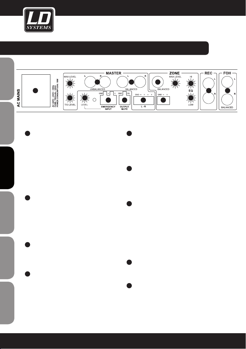
connecteUrS, CONTRÔLES ET INDICATEURS :
ENGLISHDEUTSCHFRANCAIS
21
22
ESpAñoLpoLSKIITALIANo
23
FRANCAISFRANCAIS FRANCAISFRANCAIS
24
23
21
22
EMBASE SECTEUR IEC AVEC PORTE-FUSIBLE
INTÉGRÉ
AVERTISSEMENT IMPORTANT : Assurez-vous
AVANT la mise en service que la tension secteur
disponible correspond à celle de l'appareil.
Remplacez exclusivement le fusible par un fusible
neuf du même format et du même calibre (valeurs
indiquées sur le panneau arrière de l'appareil). Si
le fusible fond de façon répétée, veuillez consulter
un centre de réparations agréé.
T/O LEVEL
Cet ajustable permet de régler la sensibilité de la
fonction Talkover (intensité de l'atténuation des
sources en fonction du niveau du signal micro).
La fonction Talkover est disponible sur les sorties
ligne MASTER et ZONE (sélecteur SOURCE en
position MIX).
MASTER MAX LEVEL
Réglez, avec un tournevis, le niveau maximal
que le signal de la sortie MASTER ne doit pas
dépasser.
MASTER OUTPUT L/R UNBALANCED
Sortie stéréo (gauche/droite) asymétrique sur
connecteurs RCA/cinch. Le signal envoyé sur la
sortie ZONE est soit un mixage des signaux des
entrées MIC 1 / 2, INPUT 1 à 5 et FOH.
24 25
28
30
32
33
29
2627
25
MASTER OUTPUT L/R BALANCED
Sortie stéréo (gauche/droite) symétrique sur
connecteurs jack 6,35 mm. Le signal envoyé sur
la sortie ZONE est soit un mixage des signaux des
entrées MIC 1 / 2, INPUT 1 à 5 et FOH.
26
MASTER OUTPUT L/R BALANCED
Sortie stéréo (gauche/droite) symétrique sur
connecteurs Eurobloc (livrés). Le signal envoyé sur
la sortie ZONE est soit un mixage des signaux des
entrées MIC 1 / 2, INPUT 1 à 5 et FOH.
27
EMERGENCY INPUT
Connecteur Eurobloc symétrique pour système
acoustique d'urgence (Eurobloc livré). Dès qu'arrive
sur cette entrée un signal audio au niveau ligne,
toutes les entrées micro et ligne sont coupées, et
le signal d'urgence est envoyé directement sur les
sorties ligne MASTER et ZONE. Les potentiomètres
de réglage de volume des canaux de sortie MASTER
et ZONE sont alors inactifs.
28
EMERGENCY INPUT LEVEL
Cet ajustable permet de régler, avec un tournevis,
le volume de diffusion du signal d'urgence.
29
OUTPUT MUTE
Entrée Eurobloc pour contact sec ou contrôleur de
Mute (connecteur Eurobloc livré). À la fermeture
du contact, tous les canaux d'entrée sont coupés
(Mute), à l'exception du signal EMERGENCY INPUT.
31
34
35 36
44
Page 45

connecteUrS, CONTRÔLES ET INDICATEURS :
38
37
45
30
ZONE OUTPUT BALANCED
Sortie stéréo (gauche/droite) symétrique sur
connecteurs XLR. Le signal envoyé sur la sortie
ZONE est soit un mixage des signaux des entrées
MIC 1 / 2, INPUT 1 - 5 et FOH (sélecteur n°14, ZONE
SOURCE, en face avant, sur MIX), soit le signal d'une
des entrées 1 à 5 (sélecteur n°14, ZONE SOURCE, en
face avant, sur une des entrées INPUT 1 à 5).
31
ZONE OUTPUT BALANCED
Sortie stéréo (gauche/droite) symétrique sur
connecteur Eurobloc (livré). Le signal envoyé sur
la sortie ZONE est soit un mixage des signaux des
entrées MIC 1 / 2, INPUT 1 - 5 et FOH (sélecteur
n°14, ZONE SOURCE, en face avant, sur MIX), soit
le signal d'une des entrées 1 à 5 (sélecteur n°14,
ZONE SOURCE, en face avant, sur une des entrées
INPUT 1 à 5).
32
ZONE MAX LEVEL
Réglez, avec un tournevis, le niveau maximal que
le signal de la sortie ZONE ne doit pas dépasser.
33
ZONE EQ HIGH
Correcteur d'aigus pour le canal de sortie ZONE.
Tourner vers la gauche pour baisser les aigus,
vers la droite pour les monter. En position centrale
(crantée), le correcteur est inactif.
38
38
41 42
39
40
34
ZONE EQ LOW
Correcteur de graves pour le canal de sortie ZONE.
Tourner vers la gauche pour baisser les graves,
vers la droite pour les monter. En position centrale
(crantée), le correcteur est inactif.
35
REC OUTPUT L/R
Sortie stéréo (gauche/droite) asymétrique au
niveau ligne, sur connecteurs RCA/cinch. Le
signal envoyé sur la sortie REC est un mixage des
signaux des entrées MIC 1 / 2, INPUT 1 - 5 et FOH.
Son niveau de sortie ne dépend pas de la position
du potentiomètre de volume de la sortie MASTER
; le signal REC OUTPUT est prélevé avant les
égaliseurs, il n'est donc pas corrigé.
36
FOH INPUT L/R
Entrée stéréo (gauche/droite) symétrique sur
connecteurs jack 6,35 mm. Permet de connecter
une source de signal audio externe (par exemple,
console de mixage).
37
LINE IN 3 - 5
Entrées stéréo asymétrique au niveau ligne 3 à 5,
sur connecteurs RCA/cinch.
38
TRIM 3 - 5
Ces potentiomètres de gain permettent d'adapter
la sensibilité des entrées correspondantes au
niveau de sortie des différentes sources ; ils se
règlent avec un tournevis.
Le canal d'entrée 5 peut également recevoir le
flux audio arrivant sur le port USB.
41
39
42
40
4337 37
44
FRANCAISFRANCAIS FRANCAISFRANCAIS
FRANCAISDEUTSCHENGLISH
ITALIANOPOLSKIESPAÑOL
45
Page 46

connecteUrS, CONTRÔLES ET INDICATEURS :
39
ENGLISHDEUTSCHFRANCAIS
40
41
42
43
ESpAñoLpoLSKIITALIANo
44
FRANCAISFRANCAIS FRANCAISFRANCAIS
LINE INPUT 1 - 2
Entrées stéréo asymétrique au niveau ligne 1 et 2,
sur connecteurs RCA/cinch.
MIC INPUT 1 - 2
Entrées Micro symétriques 1 et 2, sur connecteurs
jack 6,35 mm. Ces deux entrées Micro ne fournissent pas de tension d'alimentation fantôme.
SÉLECTEUR MIC INPUT 1 - 2
Lorsque cette touche est enfoncée, c'est l'entrée
micro qui est activée sur le canal correspondant :
le signal au niveau ligne est coupé.
TRIM INPUT 1 - 2
Touche 41 non enfoncée : Ces potentiomètres
de gain permettent d'adapter la sensibilité des
entrées 1 et 2 au niveau de sortie des différentes
sources ; ils se règlent avec un tournevis.
Touche 41 enfoncée : Préampli micro activé sur
l'entrée. Le gain se règle avec un tournevis.
MIC 1 - 2
Entrées Micro symétriques 1 et 2, sur connecteurs
jack 6,35 mm. Les deux entrées Micro fournissent
une tension d'alimentation fantôme 12 Volts.
USB
Ce port USB (protocole USB 1.1) permet d'utiliser
le mixeur en tant qu'interface audio. Vous pouvez
alors utiliser le ZONE 423 pour lire et enregistrer
des données audio sur un ordinateur connecté,
tournant sous Mac OS (Mac OS X 10.5 et ultérieurs)
ou Windows (XP, Vista, 7, 8). Il n'est pas nécessaire
d'installer des pilotes spécifiques. Après connexion
du mixeur sur un des ports USB de l'ordinateur
(protocole USB 1.1 ou USB 2.0), les pilotes nécessaires
sont installés automatiquement, et le ZONE 423
apparaît sous le nom de "USB Audio CODEC" dans
le tableau de bord Son du Mac ou le panneau de
configuration du PC.
Le signal enregistré est le mixage de sortie, prélevé
avant passage par le potentiomètre de réglage de
niveau Master et le limiteur Max Level. La lecture audio
s'effectue sur l'entrée Ligne INPUT 5. Pour ce faire, il
suffit d'enfoncer la touche 45 sur le panneau arrière
(position USB).
45
USB / LINE
Touche de sélection de source de signal pour le
canal d'entrée INPUT 5. Lorsque cette touche est
enfoncée, c'est le signal issu du port USB (44) qui
est sélectionné ; sinon, c'est le signal présent sur
l'entrée ligne (37).
46
Page 47

FRANCAISFRANCAIS FRANCAISFRANCAIS
FRANCAISDEUTSCHENGLISH
ITALIANOPOLSKIESPAÑOL
47
Page 48

exempLe DE CÂBLAGE :
ENGLISHDEUTSCHFRANCAIS
ESpAñoLpoLSKIITALIANo
FRANCAISFRANCAIS FRANCAISFRANCAIS
48
Dispositif acoustique d'alerte
Contact sec / contrôleur de Mute
Page 49

exempLe DE CÂBLAGE :
FRANCAISFRANCAIS FRANCAISFRANCAIS
FRANCAISDEUTSCHENGLISH
ITALIANOPOLSKIESPAÑOL
49
Page 50

CARACTÉRISTIQUES :
Référence modèle : LDZONE622
Type de produit : Mixeur de zones
ENGLISHDEUTSCHFRANCAIS
ESpAñoLpoLSKIITALIANo
FRANCAISFRANCAIS FRANCAISFRANCAIS
Type : stéréo
Nombre Total de Canaux d'Entrée : 8 (2 x Mic, 2 x Mic/Line, 3 x Line, 1 x FOH)
Réponse en Fréquence : 20 - 40000 Hz
Nombre de Voies Micro : 2 (avec alimentation fantôme 12 Volts)
Connecteurs sur Voies Micro : jack 6,35 mm (symétrique)
Contrôles sur Voies Micro : Gain, On/Off, 1 x EQ Hi, 1 x EQ Low, 1 x Talk Over
Indicateurs sur Voie Micro : LED "On"
Impédance d'Entrée sur Voie Micro : 4 kohms
Sensibilité d'Entrée sur Voie Micro : 6,1 mV
Taux de Distorsion Harmonique Totale sur Voie Micro : 0,08 %
Nombre de Voies Ligne/Micro : 2
Connecteurs d'Entrée sur Voie Ligne/Micro : 2 x RCA/cinch, jack 6,35 mm (asymétrique), mini-jack
Contrôles Voie Ligne/Micro : Level, Cue, Mic/Line, Trim
Indicateurs Voie Ligne/Micro : LED Signal, LED Cue
Nombre de Voies Ligne : 3
Connecteurs Entrées Ligne : 2 x RCA (cinch)
Contrôles sur Voies Ligne : Level, Cue, Trim
Indicateurs sur Voie Ligne : LED Signal, LED Cue
Impédance d'Entrée sur Voie Ligne : 4 kohms
Sensibilité d'Entrée Voie Ligne : 1,5 V
Taux de Distorsion Harmonique Totale sur Voies Ligne : 0,03 %
Sensibilité d'Entrée AUX/Line
(mini-jack stéréo 3,5 mm) :
Voie FOH : 1
Connecteurs Entrée FOH : 2 x jacks 6,35 mm symétriques
Contrôles Voie FOH : Level, Cue
Indicateurs Voie FOH : LED Signal, LED Cue
Sorties Ligne : 3 (Master [stéréo], Zone [mono], Rec [stéréo])
Damp, 1 x Talk Over Level
stéréo 3,5 mm (Input 1)
3 V
50
Page 51

CARACTÉRISTIQUES :
Connecteurs Sortie Master : 2 x jacks 6,35 mm symétriques, 2 x RCA/cinch,
Eurobloc
Contrôles Sortie Master : Level, EQ Hi, EQ Low, Max. Level
Indicateurs Sortie Master : Indicateur de niveau 5 segments
Niveau Maximal de Sortie Master : +24 dBu (symétrique), 18 dBu (asymétrique)
Connecteurs de Sortie Zone : jack 6,35 mm TRS (symétrique), Eurobloc
Contrôles de Sortie Zone : Level, EQ Hi, EQ Low, Max. Level, Source Input 1-5/Mix
Indicateurs de Sortie Zone : Indicateur de niveau 5 segments
Niveau Maximal de Sortie Zone : +24 dBu (symétrique/asymétrique)
Connecteurs Sortie Rec : 2 x RCA (cinch)
Sortie Casque : 1
Type de Connecteur : jack 6,35 mm stéréo
Contrôle Sortie Casque : Volume Cue
Tension Maximale de Sortie Casque : 1,25 Volts sur 32 Ohms
Autres Entrées : 2 (Emergency Input, Output Mute)
Connecteurs Autres Entrées : Eurobloc
Contrôles Autres Entrées : Niveau Emergency Input
Autres Contrôles : interrupteur secteur (Power)
Autres Indicateurs : LED Power
Tension d'Alimentation : 220 - 250 V AC, 50 Hz
Embase Secteur : Embase IEC
Consommation Électrique (maxi) : 18 W
Fusible : T 500 mAL / 250 V
Dimensions (L x H x P) : 485 x 44 x 179 mm
Masse: 2,44 kg
Accessoires Livrés : connecteurs Eurobloc, câble secteur, manuel utilisateur
Divers : Port USB 1.1 (compatible 2.0) pour utilisation comme
interface audio (enregistrement et lecture stéréo, résolution
16 bits). Systèmes d'exploitation compatibles : Mac OS X
(10.5 et ultérieurs), Windows XP, Vista, 7, 8
FRANCAISFRANCAIS FRANCAISFRANCAIS
FRANCAISDEUTSCHENGLISH
ITALIANOPOLSKIESPAÑOL
51
Page 52
DECLARATIONS DecLarationS :
GARANTIE FABRICANT LIMITÉE
Cette garantie concerne tous les produits de marque Adam Hall, LD Systems, Defender, Palmer et Cameo.
Elle s‘applique également à tous les produits distribués par Adam Hall.
ENGLISHDEUTSCHFRANCAIS
Elle ne concerne pas les droits statutaires relatifs à la garantie envers le vendeur. En fait, elle justifie des requêtes
en garantie supplémentaires, indépendantes, envers Adam Hall.
Adam Hall garantit, pendant une période s‘étendant selon le cas de deux à cinq ans (à vérifier selon le produit) à
compter de la date d‘achat, que le produit Adam Hall que vous avez acheté directement auprès d‘Adam Hall ou
chez un revendeur autorisé est dépourvu de défaut, au niveau des composants ou de la fabrication, dans le cadre
d‘une utilisation normale.
La période pendant laquelle cette garantie limitée est applicable commence à partir de la date d‘achat. Cette date
se justifie d‘après une facture ou un bon de livraison daté. Dans le cas où des produits des marques citées ci
avant nécessiteraient une réparation pendant la période de garantie limitée, vous avez droit à des réparations sous
garantie, conformément aux termes et conditions exposés dans ce document.
Pendant toute la période de garantie limitée, Adam Hall réparera ou procédera au remplacement de tous les composants défectueux, ou le produit lui-même. En cas de réparation ou d‘échange pendant la période de garantie, les
pièces originales remplacées ou le produit échangé deviennent la propriété de la société Adam Hall.
Dans le cas improbable où votre produit Adam Hall serait sujet à des défaillances répétées, Adam Hall, à sa discrétion, peut choisir de mettre à votre disposition un appareil de remplacement de son choix, au moins équivalent à
votre produit de marque Adam Hall en termes de performances matérielles et techniques.
Adam Hall ne garantit pas que l‘utilisation de ce produit ne sera sujette à aucune interruption ni défaillance.
Adam Hall n‘est pas responsable des dommages occasionnés par le non-respect des instructions contenues dans
ESpAñoLpoLSKIITALIANo
le manuel d‘utilisation livré avec le produit de marque Adam Hall. La garantie fabricant ne s‘applique pas- aux
pièces d‘usure (accumulateurs par exemple) - aux produits dont le numéro de série a été effacé, ou qui ont été
endommagés ou rendus inutilisables à la suite d‘un accident - aux dommages provoqués une utilisation peu
précautionneuse, à une erreur de manipulation ou tout autre motif externe.
- en cas de dommages subis par des appareils suite à une utilisation hors des valeurs d‘usage des paramètres
(telles que mentionnées dans le manuel utilisateur livré avec le produit)
- en cas de dommages consécutifs à l‘utilisation de pièces de rechange non fabriquées ou non vendues par Adam
FRANCAISFRANCAIS FRANCAISFRANCAIS
Hall
- en cas de dommages consécutifs à des modifications ou réparations non assurées par Adam Hall
Ces termes et conditions constituent l‘accord de garantie complet et exclusif entre cous et Adam Hall, relativement
au produit de marque Adam Hall que vous avez acheté.
52
Page 53

DECLARATIONS DecLarationS :
RESPONSABILITÉ LIMITÉE
Si votre appareil de marque Adam Hall présente, pendant la période de garantie, des défaillances au niveau des
composants ou de la fabrication, couvertes par les conditions ci avant, le seul recours, exclusif, est sa réparation
ou son remplacement au titre de cette garantie. Dans le cadre de cette garantie limitée, la responsabilité financière maximale d‘Adam Hall est expressément limitée à la plus faible des deux sommes suivantes : prix d‘achat
payé pour le produit ou coût de réparation ou de remplacement de tout composant matériel ne fonctionnant pas
correctement dans des conditions normales d‘utilisation.
Adam Hall ne peut être tenu pour financièrement responsable de tout dommage causé par le produit ou sa
défaillance – y compris toute perte de recettes ou de bénéfices, ni de tout dommage spécifique, incidentel ou
consécutif. De plus, Adam Hall n‘est pas responsable financièrement en cas de requête émanant d‘une tierce
partie ou de votre part pour le compte d‘une tierce partie.
Cette limitation de responsabilité financière s‘applique en cas de demande de dommages et intérêts ou de
poursuites, dans le cadre de cette garantie limitée ou en cas de procédure (négligence et stricte responsabilité
produit), de non-respect du contrat, ou de toute autre procédure. Cette limitation de responsabilité financière
ne peut être annulée ou amendée par quiconque. Cette limitation de responsabilité financière s‘applique même
si vous avez prévenu Adam Hall ou tout représentant autorisé de Adam Hall de la possibilité de tels dommages.
Toutefois, cette limitation de responsabilité financière ne s‘applique pas en cas de blessures aux personnes.
Cette garantie fabricant limitée vous donne des droits légaux spécifiques. Vous pouvez également avoir d‘autres
droits, variables d‘un état ou d‘un pays à l‘autre. Nous vous conseillons de vous reporter aux lois applicables
dans votre état ou votre pays afin de déterminer l‘étendue exacte de vos droits.
DEMANDE DE RÉPARATIONS SOUS GARANTIE
Pour demander des réparations sous garantie pour votre produit, veuillez contacter Adam Hall ou le revendeur
agréé Adam Hall auprès de qui vous l‘avez acheté.
FRANCAISFRANCAIS FRANCAISFRANCAIS
FRANCAISDEUTSCHENGLISH
DÉcLaration De CONFORMITÉ CE
Les appareils commercialisés par Adam Hall répondent (à la date actuelle) aux exigences et spécifications applicables des Directives 1999/5/EC (R&TTE), 2004/108/EC (EMC) et 2006/95/EC (LVD). Pour plus d‘informations,
référez-vous au site www.adamhall.com.
ITALIANOPOLSKIESPAÑOL
53
Page 54

DECLARATIONS DecLarationS :
MISE AU REBUT DE CE PRODUIT
(Applicable dans l‘Union Européenne et les autres pays européens dotés de systèmes de collecte sélective)
La présence de ce logo sur le produit ou son manuel d‘utilisation indique qu‘en fin de vie, il ne doit pas être
ENGLISHDEUTSCHFRANCAIS
jeté avec les autres déchets domestiques. Afin d‘éviter toute atteinte à l‘environnement ou à la santé humaine
pouvant résulter d‘une gestion incontrôlée des déchets, veuillez assurer son recyclage de manière responsable.
Séparez-le des autres types de déchets et recyclez-le, afin de promouvoir la réutilisation durable des ressources
naturelles.
Nous conseillons aux utilisateurs non professionnels de contacter le revendeur chez qui ils ont acheté le produit,
ou un représentant gouvernemental local, pour plus de détails sur le lieu de collecte et la façon de recycler cet
appareil dans le meilleur respect de l‘environnement possible..
Nous invitons les utilisateurs professionnels à contacter leur fournisseur et à vérifier les termes et conditions de
leur contrat d‘achat. Ce produit ne doit pas être mélangé à d‘autres déchets commerciaux lors de la collecte.
PROTECTION DE L'ENVIRONNEMENT et ÉconomieS D'ÉnerGie
Économiser l'énergie constitue une contribution active efficace à la protection de l'environnement. Pensez à
éteindre tout appareil électrique dès que vous ne vous en servez plus. Pour éviter que les appareils placés en
mode de veille (Standby) ne continuent à consommer de l'électricité, débranchez-les de leur prise secteur.
ESpAñoLpoLSKIITALIANo
FRANCAISFRANCAIS FRANCAISFRANCAIS
Adam Hall GmbH, tous droits réservés. Les caractéristiques techniques et les fonctions disponibles sur le produit
sont sujettes à modifications. La photocopie, la traduction et toute forme de copie, partielle ou intégrale, de ce
manuel utilisateur sont interdites.
54
Page 55

FRANCAISFRANCAIS FRANCAISFRANCAIS
FRANCAISDEUTSCHENGLISH
ITALIANOPOLSKIESPAÑOL
55
Page 56

ENGLISHDEUTSCHFRANCAIS
¡Gracias por elegir LD-Systems!
Este equipo está diseñado y fabricado con los estándares de calidad más exigentes, para garantizar un correcto
funcionamiento durante muchos años. Los productos de LD-Systems se caracterizan por su gran calidad, avalada
por el prestigio de la marca y una dilatada experiencia como fabricante.
Lea atentamente este manual de usuario para poder aprovechar rápidamente toda la funcionalidad de su nuevo
producto de LD Systems.
Si desea obtener información sobre LD-SYSTEMS, visite nuestro sitio web WWW.LD-SYSTEMS.COM
Introducción
El mezclador de zonas ZONE 622 es un equipo muy compacto en formato rack de 1U de altura provisto de
ESpAñoLpoLSKIITALIANo
6canales de línea y 2 de micro, que pueden asignarse a una salida principal estéreo y a otra salida principal mono.
Entre otras funciones esenciales, dispone de una entrada para un sistema externo de avisos de emergencia con su
control de volumen y de un conector para silenciado remoto. El mezclador ZONE622 es ideal para sonorizar zonas
separadas en restaurantes, clubes, hoteles o centros de fitness, y también para presentaciones.
FRANCAISFRANCAIS FRANCAISFRANCAIS
56
Page 57

MEZCLADOR DE 2 ZONAS
para rack
LDzONE622
FRANCAISFRANCAIS FRANCAISFRANCAIS
FRANCAISDEUTSCHENGLISH
ITALIANOPOLSKIESPAÑOL
57
Page 58

MEDIDAS De SeGUriDaD:
1. Lea atentamente las instrucciones de este manual.
2. Guarde toda la información en un lugar seguro para futuras consultas.
3. Siga las instrucciones indicadas.
4. Siga todas las advertencias. No quite las instrucciones de seguridad ni cualquier otra información indicada en el equipo.
5. Utilice el equipo únicamente según la finalidad prevista.
ENGLISHDEUTSCHFRANCAIS
6. Utilice solo soportes y fijaciones que sean robustos y adecuados cuando instale el equipo en instalaciones
fijas. Asegúrese de que los soportes de pared están correctamente instalados y firmemente fijados. Asegúrese de
que el equipo está sólidamente instalado y no se puede caer.
7. Al instalar el equipo, respete las normas de seguridad aplicables en su país.
8. Evite instalar el equipo cerca de radiadores, acumuladores de calor, estufas o cualquier otra fuente de calor. Asegúrese de que el equipo esté instalado en un lugar con ventilación suficiente para evitar cualquier sobrecalentamiento.
9. No coloque sobre el equipo fuentes de llamas sin protección, por ejemplo, velas encendidas.
10. Evite bloquear las rejillas de ventilación.
11. No utilice este equipo cerca del agua (excepto los equipos específicamente diseñados para uso en exterior,
en cuyo caso tenga en cuenta las indicaciones mencionadas a continuación). No exponga este equipo a materiales, líquidos o gases inflamables.
12. Evite exponer el equipo a gotas o salpicaduras que puedan caer dentro del mismo. No coloque recipientes
llenos de líquido, como floreros o vasos, sobre el equipo.
13. Asegúrese de no dejar caer ningún objeto dentro del equipo.
14. Emplee el equipo únicamente con los accesorios recomendados por el fabricante.
15. No abra el equipo ni intente modificarlo.
16. Una vez conectado el equipo, compruebe que en toda la longitud del cableado no hay peligro de que provoque una caída, por ejemplo.
17. Durante el transporte, asegúrese de que el equipo no se caiga y pueda causar daños personales o materiales.
18. Si el equipo no funciona correctamente, o si se ha vertido líquido sobre él, o si un objeto ha caído en su
interior o si ha sufrido algún desperfecto, apague inmediatamente el equipo y desenchufe el cable eléctrico (si se
trata de un equipo activo). Únicamente un técnico especialista debe reparar el equipo.
19. Para limpiar el equipo utilice un paño seco.
ESpAñoLpoLSKIITALIANo
20. Procure seguir las normas vigentes en su país sobre reciclaje de desechos. Separe los componentes de
plástico, papel y cartón del paquete para reciclarlos en sus contenedores respectivos.
21. No deje las bolsas de plástico al alcance de los niños.
PARA LOS EQUIPOS CON TOMA ELÉCTRICA:
22. ADVERTENCIA: Si el cable eléctrico está provisto de un contacto de protección, debe conectarse a una toma
eléctrica con conexión a tierra. No desactivar nunca esta conexión de protección a tierra del cable eléctrico.
FRANCAISFRANCAIS FRANCAISFRANCAIS
23. Si el equipo ha estado expuesto a un cambio brusco de temperatura (por ejemplo, después del transporte),
no lo encienda inmediatamente. La condensación o la humedad podrían dañar el equipo. Deje que el equipo
alcance la temperatura ambiente antes de encenderlo.
24. Antes de conectar el cable eléctrico a la toma de corriente, compruebe si la tensión y la frecuencia del
suministro eléctrico coinciden con las especificaciones de este equipo. Si el equipo dispone de un selector de
tensión, antes de enchufarlo a la red eléctrica, asegúrese de que el valor seleccionado coincide con la tensión de
suministro. Si el enchufe o el adaptador de corriente no encajan en la toma eléctrica, consulte a un electricista.
25. Asegúrese de que el cable eléctrico no está pinzado. Evite que el cable resulte pellizcado, sobre todo en los
extremos de conexión al equipo y en la toma eléctrica.
26. Al conectar el equipo, asegúrese de que el cable eléctrico o el adaptador de corriente estén siempre
accesibles. Desconecte el equipo de la toma de corriente cuando no esté en uso o antes de limpiarlo. Para ello,
58
Page 59

SEGURIDAD:
desconecte el cable eléctrico y el adaptador de corriente del conector del equipo en vez de desenchufar el cable
de la toma eléctrica. No tocar el cable eléctrico ni el adaptador de corriente con las manos húmedas.
27. No encienda y apague el equipo en cortos intervalos de tiempo, ya que se reduce así la vida útil del sistema.
28. NOTA IMPORTANTE: Sustituya los fusibles únicamente por otros del mismo tipo y de las mismas características. Si el fusible se funde continuamente, póngase en contacto con un servicio técnico autorizado.
29. Para desconectar completamente el equipo de la tensión eléctrica, desenchufe el cable eléctrico o el adaptador de corriente de la toma eléctrica.
30. Si el equipo dispone de un enchufe eléctrico Volex, deberá desbloquearse el Volex del equipo para desenchufarlo. Esto implica que un tirón en el cable eléctrico puede desplazar el equipo y provocar daños personales o
materiales. Por tanto, asegúrese de instalar los cables con sumo cuidado.
31. Si es probable que caiga un rayo por una tormenta eléctrica o si no va a emplear el equipo durante mucho
tiempo, desenchufe el cable eléctrico y el adaptador de corriente.
CAUTION
RISK OF ELECTRIC SHOCK
DO NOT OPEN
ADVERTENCIA:
Para evitar el riesgo de descarga eléctrica, no retire la tapa. El equipo no contiene piezas que el usuario pueda
reparar o sustituir. Para cualquier tarea de mantenimiento o reparación, acuda a un técnico cualificado.
El símbolo de rayo dentro de un triángulo equilátero advierte al usuario de la presencia de tensiones
peligrosas sin aislamiento dentro del equipo que pueden causar una descarga eléctrica y suponer un
riesgo para la salud.
El símbolo de exclamación dentro de un triángulo equilátero advierte al usuario de la existencia de
importantes instrucciones de uso y mantenimiento.
FRANCAISFRANCAIS FRANCAISFRANCAIS
FRANCAISDEUTSCHENGLISH
ADVERTENCIA: ¡ALTO VOLUMEN!
Este equipo se destina a un uso profesional. Por consiguiente, si se aplica a un uso comercial, estará sujeto a
las normas y reglamentos de la Asociación para la prevención de accidentes de su sector profesional. Como
fabricante, Adam Hall tiene la obligación de informar formalmente a los usuarios de la existencia de posibles
riesgos para la salud.
Daños auditivos por exposición prolongada a un nivel SPL alto: este equipo puede generar fácilmente un nivel de
presión sonora (SPL) lo suficientemente elevado como para causar daños auditivos permanentes a los artistas, el
personal de producción y el público. Deben tomarse precauciones para evitar la exposición prolongada a un SPL
de más de 90 dB.
NOTA: Al instalarlo en un rack, asegúrese de que el equipo dispone de suficiente ventilación por encima y por debajo.
ITALIANOPOLSKIESPAÑOL
59
Page 60

conexioneS, CONTROLES E INDICADORES:
ENGLISHDEUTSCHFRANCAIS
1
2
3
ESpAñoLpoLSKIITALIANo
4
5
FRANCAISFRANCAIS FRANCAISFRANCAIS
2
1
3
4
6 7
5
MIC 1 / 2 ON
Botones con LED rojo para activar/desactivar los
canales de micrófono 1 y 2. En la posición pulsada,
se activa el canal de micro y se ilumina el LED.
GAIN MIC 1 / 2
Control de nivel para los canales de micrófono 1 y 2.
EQ HIGH MIC 1 / 2
Control de agudos para los canales de micro 1 y
2. Girar a la izquierda para disminuir los agudos y
a la derecha para realzarlos. En la posición central
de reposo, el control está inactivo.
EQ LOW MIC 1 / 2
Control de graves para los canales de micro 1 y 2.
Girar a la izquierda para disminuir los graves y a
la derecha para realzarlos. En la posición central
de reposo, el control está inactivo.
T/O DAMP
Función Talkover para los canales de micro 1 y 2.
Para desactivar la función Talkover, gire el control
DAMP completamente a la izquierda. Conforme
se gira el control DAMP a la derecha, las señales
de las entradas INPUT1 a 5 y FOH se ajustan para
acomodar una señal entrante de micrófono cada
vez mayor. El control T/O LEVEL del panel posterior
permite variar el umbral, es decir, la sensibilidad con
la que responde la función Talkover a la señal del
micrófono. La función Talkover no estará disponible
7
8
9
8
9
7
8
9
para la salida ZONE si se selecciona como fuente de
señal IN 1 a 5 mediante el conmutador ZONE SOURCE.
6
AUX / LINE
Entrada de línea estéreo con minijack de 3,5mm
y función de conmutación. Al conectar un minijack
de 3,5mm a esta toma, se desactiva la entrada
RCA IN 1 del panel posterior del dispositivo.
7
LEVEL (INPUT 1 A 5 Y FOH)
Control de nivel para los canales INPUT 1 a 5 y FOH.
8
CUE (INPUT 1 A 5 Y FOH)
Botón Cue con LED para los canales INPUT 1 a 5.
Al pulsar el botón, se ilumina el LED y se envía la
señal a la salida de auriculares del frontal del equipo.
Como la señal enviada se toma antes del control de
nivel LEVEL (INPUT1 a 5 y FOH) de cada canal, es
independiente del ajuste del control de nivel.
9
LED DE SEÑAL SG (INPUT 1 A 5 Y FOH)
El LED de señal se ilumina de color verde cuando
hay señal de audio a la entrada del canal.
10
EQ HIGH (MASTER)
Control de agudos para la salida MASTER. Girar
a la izquierda para disminuir los agudos y a la
derecha para realzarlos. En la posición central de
reposo, el control está inactivo.
7
8
9
60
Page 61

conexioneS, CONTROLES E INDICADORES:
13
7
8
9
11
EQ LOW (MASTER)
7
8
9
10
12
11
Control de graves para la salida MASTER. Girar
a la izquierda para disminuir los graves y a la
derecha para realzarlos. En la posición central de
reposo, el control está inactivo.
16
20
14
16
VÚMETRO DE NIVEL DE ZONA
15
17
Vúmetro LED de nivel de 5 segmentos. Si se
enciende el LED de pico (PK), el equipo funciona
al límite de distorsión. No es crítico si se ilumina
brevemente en los picos de la señal, pero evite
19
18
FRANCAISFRANCAIS FRANCAISFRANCAIS
FRANCAISDEUTSCHENGLISH
que se ilumine de forma continua reduciendo el
12
LEVEL (MASTER)
nivel de la señal.
Control de nivel para la salida MASTER del panel
posterior del equipo.
17
CUE VOLUME
Control de nivel de auriculares. Los canales que
13
VÚMETRO DE NIVEL MASTER
Vúmetro LED de nivel de 5 segmentos. Si se
enciende el LED de pico (PK), el equipo funciona
tienen pulsado su botón CUE (INPUT1 a 5 y FOH),
independientemente del ajuste de su control de
nivel, se escucharán en la salida de auriculares.
al límite de distorsión. No es crítico si se ilumina
brevemente en los picos de la señal, pero evite
que se ilumine de forma continua reduciendo el
18
SALIDA DE AURICULARES
Salida de auriculares por jack estéreo de 6,3mm.
nivel de la señal.
19
14
SOURCE (ZONE)
POWER
Interruptor de encendido/apagado del equipo.
Selección de la fuente de señal para la salida de
zona. Se puede seleccionar uno de los 5canales de
entrada (IN1 a 5), o una mezcla (MIX) de todos los
canales de entrada (MIC1 y 2, INPUT1 a 5, FOH).
20
LED POWER
Se ilumina si el equipo está encendido y correcta-
mente enchufado a la red eléctrica.
15
LEVEL (ZONE)
Control de nivel para la salida ZONE del panel
posterior del equipo.
ITALIANOPOLSKIESPAÑOL
61
Page 62
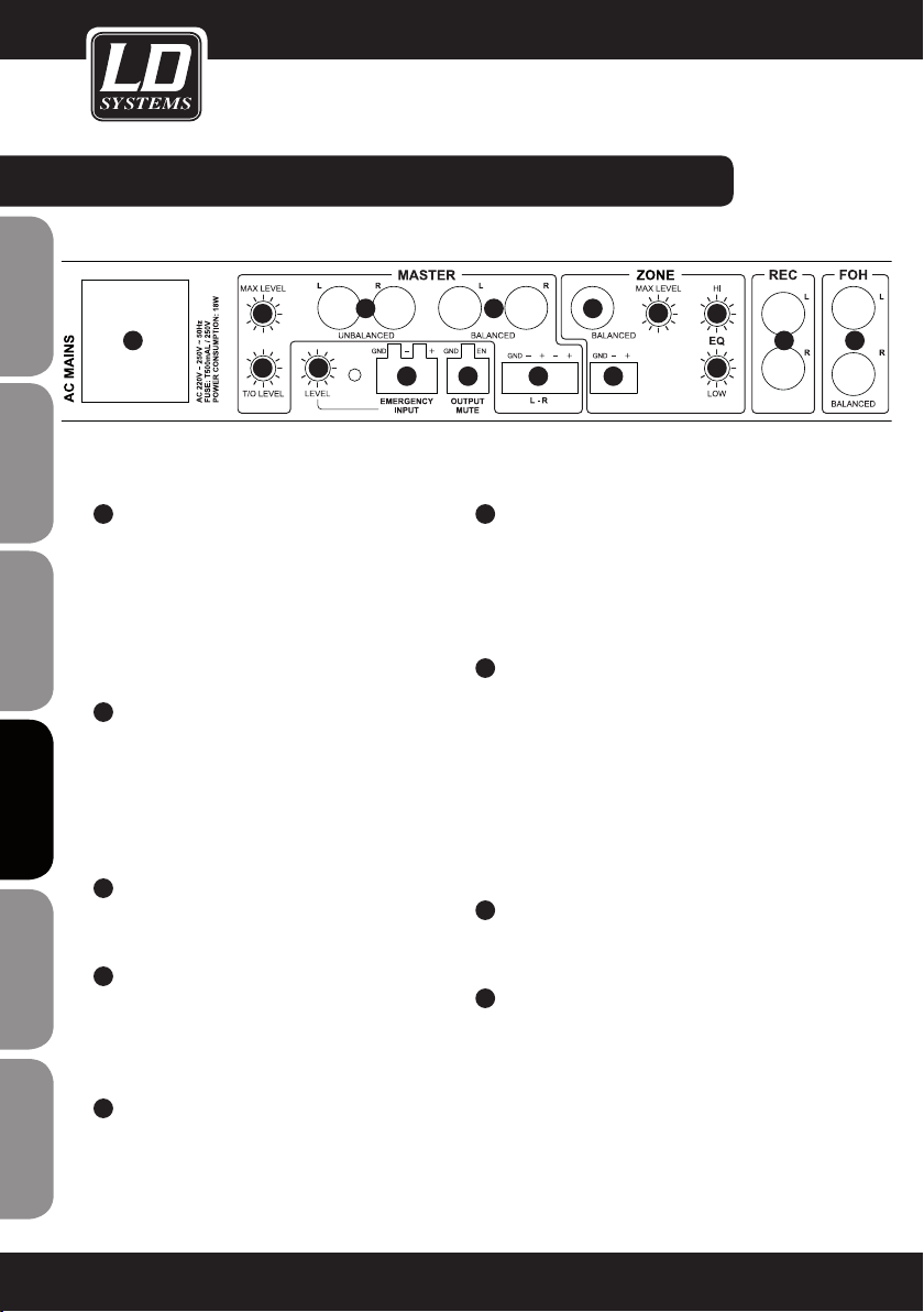
conexioneS, CONTROLES E INDICADORES:
ENGLISHDEUTSCHFRANCAIS
21
22
ESpAñoLpoLSKIITALIANo
23
24
FRANCAISFRANCAIS FRANCAISFRANCAIS
25
23
21
22
TOMA IEC CON PORTAFUSIBLES INTEGRADO
INFORMACIÓN IMPORTANTE: ¡ANTES de encender el
equipo, asegúrese de que la tensión del suministro
eléctrico coincide con la tensión del equipo! Sustituya
el fusible únicamente por otro del mismo tipo y
características (serigrafiadas en el panel posterior).
Si el fusible se fundiera continuamente, póngase en
contacto con un servicio técnico autorizado.
T/O LEVEL
El control T/O LEVEL permite variar el umbral
de Talkover, es decir, la sensibilidad con la que
responde la función Talkover a la señal del
micrófono. La función Talkover está disponible en
las salidas de línea MASTER y ZONE (conmutador
ZONE SOURCE en la posición MIX).
MAX LEVEL (MASTER)
Use un destornillador adecuado para ajustar el
nivel máximo de la salida MASTER.
SALIDA MASTER L/R NO BALANCEADA
Salida estéreo no balanceada por RCA (izquierdo/
derecho). La señal de la salida MASTER es la
suma de las señales de las entradas MIC1 y 2,
INPUT1 a 5 y FOH.
SALIDA MASTER L/R BALANCEADA
Entrada estéreo balanceada por jacks de 6,3mm
(izquierdo/derecho). La señal de la salida MASTER
es la suma de las señales de las entradas MIC1 y
2, INPUT1 a 5 y FOH.
24 25
28
30
32
33
29
2627
26
SALIDA MASTER L/R BALANCEADA
Salida estéreo balanceada (izquierdo/derecho)
por bloque de terminales (bloque de terminales
suministrado). La señal de la salida MASTER es
la suma de las señales de las entradas MIC1 y 2,
INPUT1 a 5 y FOH.
27
EMERGENCY INPUT
Conexión balanceada por bloque de terminales
para un sistema de emergencia acústico (bloque
de terminales suministrado). Cuando se aplica una
señal de audio de nivel de línea, se silenciarán
todas las entradas de micrófono y de línea, y se
conectará directamente la señal de emergencia a
las salidas de línea MASTER y ZONE. Además, se
desactivarán los controles de nivel de los canales
MASTER y ZONE.
28
LEVEL (EMERGENCY INPUT)
Use un destornillador adecuado para ajustar el
nivel de la señal de emergencia.
29
OUTPUT MUTE
Bloque de terminales para la conexión de un
contacto sin tensión o un equipo para silenciar
el audio (bloque de terminales suministrado). Si
el contacto está cerrado, se silenciarán todos los
canales de entrada, excepto EMERGENCY INPUT.
31
34
35 36
62
Page 63
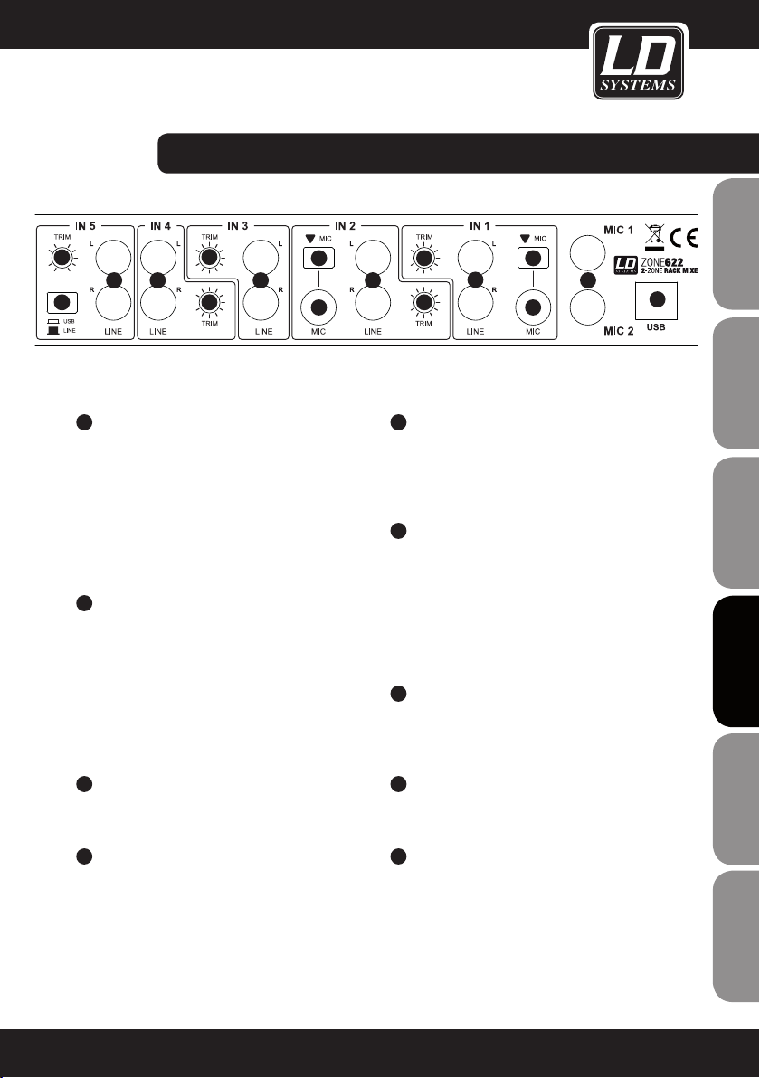
conexioneS, CONTROLES E INDICADORES:
38
37
45
30
ZONE OUTPUT BALANCEADA
Salidas mono balanceadas por jacks de 6,3mm.
La señal de la salida ZONE puede ser la suma de
las señales de las entradas MIC1 y 2, INPUT1 a 5
y FOH (conmutador14 ZONE SOURCE del frontal
del equipo en la posición MIX), o la señal de una
de las entradas INPUT1 a 5 (conmutador14 ZONE
SOURCE del frontal en una de las posiciones IN1
a 5).
31
ZONE OUTPUT BALANCEADA
Salida mono balanceada por bloque de terminales
(bloque de terminales suministrado). La señal de la
salida ZONE puede ser la suma de las señales de
las entradas MIC1 y 2, INPUT1 a 5 y FOH
(conmutador14 ZONE SOURCE del frontal del equipo
en la posición MIX), o la señal de una de las entradas
INPUT1 a 5 (conmutador14 ZONE SOURCE del
frontal en una de las posiciones IN1 a 5).
38
38
41 42
39
40
34
EQ LOW (ZONE)
Control de graves para la salida ZONE. Girar a la
izquierda para disminuir los graves y a la derecha
para realzarlos. En la posición central de reposo,
el control está inactivo.
35
SALIDA DE GRABACIÓN (L/R)
Salida de línea estéreo no balanceada por RCA
(izquierdo/derecho). La señal de la salida de grabación
es la suma de las señales de las entradas MIC1 y
2, INPUT1 a 5 y FOH. El nivel de salida depende del
ajuste del control de nivel de la salida MASTER, pero
no del ecualizador, ya que la señal se toma antes del
ecualizador.
36
ENTRADA FOH L/R
Entrada de línea estéreo balanceada por jacks de
6,3mm (izquierdo/derecho). Es posible conectar
un reproductor (como un mezclador).
41
39
42
40
4337 37
44
FRANCAISFRANCAIS FRANCAISFRANCAIS
FRANCAISDEUTSCHENGLISH
32
MAX LEVEL (ZONE)
Use un destornillador adecuado para ajustar el
nivel máximo de la salida ZONE.
33
EQ HIGH (ZONE)
Control de agudos para la salida ZONE. Girar a la
izquierda para disminuir los agudos y a la derecha
para realzarlos. En la posición central de reposo,
el control está inactivo.
37
LINE IN 3 A 5
Entradas de línea estéreo no balanceadas 3 a 5
por RCA (izquierdo/derecho).
38
TRIM 3 A 5
Use un destornillador adecuado para igualar los
diferentes niveles de salida de los equipos (como
reproductores de CD o de MP3) conectados a los
canales 3 a 5.
En el canal 5, permite igualar el nivel del puerto USB.
ITALIANOPOLSKIESPAÑOL
63
Page 64

conexioneS, CONTROLES E INDICADORES:
39
ENGLISHDEUTSCHFRANCAIS
40
41
42
43
ESpAñoLpoLSKIITALIANo
44
FRANCAISFRANCAIS FRANCAISFRANCAIS
LINE (INPUT 1 / 2)
Entradas de línea estéreo no balanceadas 1 y 2
por RCA (izquierdo/derecho).
MIC (INPUT 1 / 2)
Entradas de micrófono balanceadas INPUT1 y 2
por jacks de 6,3mm. Estas entradas de micrófono
carecen de alimentación fantasma.
BOTÓN MIC (INPUT 1 / 2)
En la posición pulsada, se selecciona la entrada
de micrófono del canal y se desactiva la entrada
de línea.
TRIM (INPUT 1 / 2)
Botón 41 sin pulsar: Use un destornillador adecuado
para igualar los diferentes niveles de salida de los
equipos (como reproductores de CD o de MP3)
conectados a los canales 3 a 5.
Botón 41 pulsado: Preamplificador de la entrada
de micrófono. Use un destornillador adecuado
para ajustar.
MIC 1 / 2
Entradas de micrófono balanceadas 1 y 2 por
jacks de 6,3mm. Ambas entradas disponen de
alimentación fantasma de 12V.
USB
Puerto USB (USB1.1) para conectar una mesa
de mezclas como equipo de audio. De esta
forma podrá grabar y reproducir audio a través
de un ordenador conectado, ya sea con el
sistema operativo Windows (Windows XP, Vista,
7, 8) o Apple Macintosh (10.5 o superior). No es
necesario instalar ningún controlador de software.
Al conectar a un puerto USB adecuado de su
ordenador (USB1.1, USB2.0), los controladores
se instalarán automáticamente, y el mezclador
se detectará como un dispositivo de audio «USB
Audio CODEC» en los ordenadores con Windows o
Apple Macintosh.
La señal de grabación es la suma de señales y se toma
después del control de nivel Master y del botón Max
Level, por lo que depende de ellos. La reproducción
de audio se realiza por el canal de línea INPUT5. Para
ello, pulse el botón45 del panel posterior del equipo
(posición USB).
45
USB / LINE
Botón para seleccionar la fuente de señal del canal de
línea INPUT5. En la posición pulsada, se selecciona el
puerto USB44 como fuente de señal; si no se pulsa,
se selecciona la entrada de línea37.
64
Page 65

FRANCAISFRANCAIS FRANCAISFRANCAIS
FRANCAISDEUTSCHENGLISH
ITALIANOPOLSKIESPAÑOL
65
Page 66

eJempLoS De CABLEADO:
ENGLISHDEUTSCHFRANCAIS
ESpAñoLpoLSKIITALIANo
FRANCAISFRANCAIS FRANCAISFRANCAIS
66
Sistema de emergencia acústico
Contactos sin tensión / Equipo para silenciar el audio
Page 67

eJempLoS De CABLEADO:
FRANCAISFRANCAIS FRANCAISFRANCAIS
FRANCAISDEUTSCHENGLISH
ITALIANOPOLSKIESPAÑOL
67
Page 68
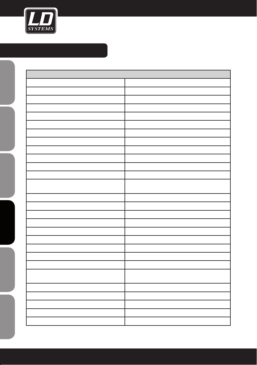
ESPECIFICACIONES:
Nombre del modelo: LDZONE622
Tipo de producto: Mezclador de zonas
ENGLISHDEUTSCHFRANCAIS
ESpAñoLpoLSKIITALIANo
FRANCAISFRANCAIS FRANCAISFRANCAIS
Tipo: Estéreo
Canales de entrada: 8 (2 de micro, 2 de micro/línea, 3 de línea, 1 de FOH)
Respuesta en frecuencia: 20 a 40.000 Hz
Canales de micrófono: 2 (con alimentación fantasma de 12V)
Conectores de los canales de micro: Jack de 6,3 mm (balanceado)
Controles de los canales de micro: Gain, On/Off, EQ Hi, EQ Low, Talkover Damp, Talkover Level
Indicadores de los canales de micro: LED ON
Impedancia de la entrada de los canales de micro: 4 Kohmios
Sensibilidad de la entrada de los canales de micro: 6,1 mV
THD de los canales de micro: 0,08%
Canales de línea/micro: 2
Conectores de las entradas de línea/micro: 2 RCA, jack de 6,3mm (no balanceado), minijack
Controles de los canales de línea/micro: Level, Cue, Mic/Line, Trim
Indicadores de los canales de línea/micro: LED de señal, LED Cue
Canales de línea: 3
Conectores de entrada de línea: 2 RCA
Controles de los canales de línea: Level, Cue, Trim
Indicadores de los canales de línea: LED de señal, LED Cue
Impedancia de la entrada de línea: 4 Kohmios
Sensibilidad de la entrada de los canales de línea: 1,5 V
THD de los canales de línea: 0,03%
Sensibilidad de la entrada de AUX/Line (minijack
estéreo de 3,5mm):
Canales FOH: 1
Conectores de la entrada FOH: 2 jacks de 6,3 mm balanceados
Indicadores de los canales de FOH: Level, Cue
Indicadores de los canales de FOH: LED de señal, LED Cue
Salidas de línea: 3 (principal estéreo, zona mono, grabación estéreo)
estéreo de 3,5mm (Input1)
3 V
68
Page 69

ESPECIFICACIONES:
Conectores de la salida principal: 2 jacks de 6,3 mm balanceados, 2RCA, bloque de
terminales
Controles de la sección principal: Nivel, EQ Hi, EQ Low, Max. Level
Indicadores de la sección principal: Vúmetro de 5 segmentos
Nivel de la salida principal: 24dBu (balanceado), 18dBu (no balanceado)
Conectores de la salida de zona: Jack de 6,3 mm balanceado, bloque de terminales
Controles de la sección de zona: Level, EQ Hi, EQ Low, Max. Level, Source Input 1-5/Mix
Indicadores de la sección de zona: Vúmetro de 5 segmentos
Nivel de salida de zona: 24 dBu (balanceado/no balanceado)
Conectores de la salida de grabación: 2 RCA
Salida de auriculares: 1
Conector de la salida de auriculares: Jack de 6,3 mm estéreo
Controles de la salida de auriculares: Cue Volume
Nivel de la salida de auriculares: 1,25 V a 32 ohmios
Entradas adicionales: 2 (Emergency Input, Output Mute)
Conectores de las entradas adicionales: Bloque de terminales
Controles de las entradas adicionales: Nivel de la entrada Emergency Input
Otros controles: Interruptor de encendido
Otros indicadores: LED POWER
Alimentación eléctrica: 220 a 250 VAC, 50 Hz
Toma eléctrica: Toma IEC
Consumo (máx.): 18 W
Fusible: T 500 mAL, 250 V
Dimensiones (An x Al x F): 485 x 44 x 179 mm
Peso: 2,44 kg
Accesorios incluidos: Bloques de terminales, cable eléctrico, manual de
usuario
Otras características: Puerto USB 1.1 (compatible con USB2.0) para usar como
equipo de audio (16bits, grabación y reproducción).
Sistemas operativos compatibles: Windows XP, Vista, 7, 8 y
Apple Macintosh 10.5 o superior
FRANCAISFRANCAIS FRANCAISFRANCAIS
FRANCAISDEUTSCHENGLISH
ITALIANOPOLSKIESPAÑOL
69
Page 70

DECLARACIÓN DeL FaBricante:
GARANTÍA DEL FABRICANTE
La presente garantía cubre las marcas Adam Hall, LD Systems, Defender, Palmer y Cameo.
Se aplica a todos los productos distribuidos por Adam Hall.
ENGLISHDEUTSCHFRANCAIS
No afecta a los derechos de garantía legal que asume el fabricante. De hecho, le concede al usuario derechos
adicionales ante Adam Hall, independientes de la garantía legal.
Adam Hall garantiza que el producto que ha adquirido de Adam Hall o de un distribuidor autorizado de Adam Hall
estará exento de defectos de material y fabricación, en condiciones normales de uso, durante un período de 2 o 5
años (consúltese el producto concreto) a partir de la fecha de compra.
La garantía limitada entra en vigor el día de la fecha de compra. Para tener derecho a esta garantía será necesario presentar un justificante de compra válido en el que figure la fecha de compra del producto, por ejemplo,
la factura o el albarán de entrega. Si el producto que ha adquirido necesitara una reparación durante la vigencia
de la garantía limitada, tendrá derecho a obtener los servicios de garantía conforme a los términos y condiciones
establecidos en este documento.
Durante el periodo de garantía limitada, Adam Hall se compromete a reparar o sustituir las piezas defectuosas del
producto. En caso de reparación o sustitución dentro del período de garantía, las piezas originales y productos
retirados pasarán a ser propiedad de Adam Hall.
En el caso poco probable de que se produzca un fallo recurrente en el producto adquirido, Adam Hall, a su entera
discreción, podrá optar por sustituir dicho producto defectuoso por otro de similares características.
Adam Hall no garantiza el funcionamiento ininterrumpido y sin fallos de este producto. Además, Adam Hall no se
hace responsable de los posibles daños ocasionados por no seguir las instrucciones de uso suministradas con el
producto Adam Hall. Esta garantía no se aplica - a los consumibles (baterías, etc.) - a los productos cuyo número
ESpAñoLpoLSKIITALIANo
de serie ha sido borrado, o que han quedado dañados y defectuosos debido a un accidente - en caso de defectos
ocasionados por una incorrecta utilización o manipulación, o cualquier otra causa ajena
- en caso de utilización del producto no conforme con los parámetros establecidos en la documentación facilitada
con el producto
- en caso de utilización de piezas de repuesto no fabricadas, no recomendadas ni vendidas por Adam Hall
- si el producto ha sido modificado o reparado por personal no autorizado por Adam Hall.
Estos términos y condiciones constituyen el acuerdo de garantía íntegro y exclusivo entre usted y Adam Hall en
FRANCAISFRANCAIS FRANCAISFRANCAIS
relación con el producto Adam Hall que acaba de adquirir.
70
Page 71

DECLARACIÓN DeL FaBricante:
LIMITACIÓN DE RESPONSABILIDAD
Si durante el período de garantía aparecen defectos de material o de fabricación en su producto Adam Hall (de
acuerdo con las garantías mencionadas en este documento), tendrá derecho exclusivamente a la reparación o
sustitución del mismo. La responsabilidad máxima de Adam Hall en virtud de los términos de esta garantía está
limitada al menor importe que resulte del precio de compra del producto, del coste de la reparación o la sustitución de las piezas que han dejado de funcionar en condiciones normales de uso.
Adam Hall no será responsable de ningún daño causado por el producto o por el mal funcionamiento del
producto, incluidas la pérdida de beneficios, la pérdida de ahorros o cualquier consecuencia derivada de dichas
pérdidas. Además, Adam Hall no se hará responsable de ninguna reclamación presentada por un tercero o por el
comprador original en nombre de un tercero.
Esta limitación de responsabilidad se aplicará con independencia de que se solicite una indemnización por daños
y perjuicios, o se presenten reclamaciones por negligencia, contractuales o de cualquier otra índole, y no podrá
ser derogada o modificada. Esta limitación de responsabilidad será efectiva incluso en el caso de que el comprador hubiese avisado previamente a Adam Hall o a alguno de sus representantes de la posibilidad de reclamar
daños y perjuicios. No obstante, esta limitación de responsabilidad no tendrá efecto en caso de reclamación por
daños personales.
Esta garantía limitada le otorga derechos legales específicos. Puede que posea derechos adicionales conforme a
la legislación del país o Estado en el que se encuentre. Le recomendamos que consulte la legislación vigente en
su país o Estado para conocer el alcance de sus derechos.
APLICACIÓN DE LA GARANTÍA
Para solicitar asistencia técnica en relación con el producto en garantía, póngase en contacto con Adam Hall o
con el distribuidor autorizado donde adquirió el producto.
FRANCAISFRANCAIS FRANCAISFRANCAIS
FRANCAISDEUTSCHENGLISH
DECLARACIÓN CE De conFormiDaD
Los productos distribuidos por Adam Hall cumplen (según proceda) los requisitos esenciales de las Directivas
europeas 1999/5/CE (Equipos radioeléctricos y equipos terminales de telecomunicación, R&TTE), 2004/108/
CE (Compatibilidad Electromagnética) y 2006/95/CE (Baja Tensión), así como las correspondientes cláusulas
adicionales. Para más información consulte www.adamhall.com.
ITALIANOPOLSKIESPAÑOL
71
Page 72

DECLARACIÓN DeL FaBricante:
ELIMINACIÓN CORRECTA DE ESTE PRODUCTO
(Aplicable en la Unión Europea y en los países europeos que dispongan de un sistema de recogida selectiva)
El símbolo que aparece sobre el producto o en la documentación adjunta indica que al final de la vida útil del
ENGLISHDEUTSCHFRANCAIS
equipo, no deberá desecharlo con los demás residuos domésticos, con el fin de evitar posibles efectos negativos
en el medio ambiente y en la salud humana debidos al vertido incontrolado de desechos. La recogida selectiva
ayuda a su posterior reciclaje y fomenta la reutilización sostenible de los componentes de este equipo.
Si es un particular, póngase en contacto con el distribuidor donde adquirió este producto, o con el ayuntamiento,
para informarse sobre el reciclaje adecuado de este equipo.
Si es una empresa, póngase en contacto con su proveedor para informarse sobre los términos y condiciones de
su contrato de compra-venta. Este producto no debe mezclarse con otros residuos industriales.
PROTECCIÓN MEDIOAMBIENTAL Y ahorro enerGÉtico
Ahorre energía eléctrica para proteger el medio ambiente. Para ello, apague todos los aparatos eléctricos cuando
no estén en uso. Además, para evitar el consumo de energía en modo En espera, desenchufe todo aparato
eléctrico de la toma de corriente cuando no esté en uso.
ESpAñoLpoLSKIITALIANo
FRANCAISFRANCAIS FRANCAISFRANCAIS
Adam Hall GmbH. Todos los derechos reservados. Los datos técnicos y las características funcionales del producto están sujetos a modificaciones. Se prohíbe la fotocopia, traducción y cualquier otra forma de reproducción
parcial o total de este manual de usuario.
72
Page 73

FRANCAISFRANCAIS FRANCAISFRANCAIS
FRANCAISDEUTSCHENGLISH
ITALIANOPOLSKIESPAÑOL
73
Page 74
ENGLISHDEUTSCHFRANCAIS
Gratulujemy wyboru!
To urządzenie zostało zaprojektowane i wyprodukowane przy zastosowaniu najwyższych kryteriów jakościowych
w celu zapewnienia wieloletniej bezawaryjnej eksploatacji. Firma LD Systems gwarantuje to swoją marką i
wieloletnim doświadczeniem w wytwarzaniu wysokiej jakości produktów audio.
Proszę starannie przeczytać niniejszą instrukcję obsługi, aby móc jak najszybciej zacząć użytkować ten produkt
marki LD Systems.
Dalsze informacje na temat firmy LD SYSTEMS dostępne są na naszej stronie internetowej WWW.LD-SYSTEMS.COM
Wprowadzenie
Urządzenie ZONE 423 to wyjątkowo kompaktowy mikser strefowy 1U z 6 kanałami liniowymi i 2 kanałami mikro-
ESpAñoLpoLSKIITALIANo
fonowymi, które mogą zostać przypisane do wyjścia stereo master i mono master. Urządzenie jest wyposażone we
wszystkie najważniejsze funkcje, jedno wejście dla zewnętrznego awaryjnego systemu komunikatów z regulatorem
głośności oraz jedno przyłącze do zdalnie sterowanego wyciszenia. Mikser ZONE 622 może być stosowany w systemach
nagłośnieniowych oddzielnych stref w restauracjach, klubach, hotelach, klubach fitness, jak również do obsługi prezentacji.
FRANCAISFRANCAIS FRANCAISFRANCAIS
74
Page 75

DWUSTREFOWY
mikSer rack
LDzONE622
FRANCAISFRANCAIS FRANCAISFRANCAIS
FRANCAISDEUTSCHENGLISH
ITALIANOPOLSKIESPAÑOL
75
Page 76

ŚRODKI oStroŻnoŚci:
1. Należy dokładnie przeczytać niniejszą instrukcję.
2. Wszystkie informacje i instrukcje przechowywać w bezpiecznym miejscu.
3. Należy przestrzegać zaleceń.
4. Należy przestrzegać wszystkich wskazówek ostrzegawczych. Nie wolno usuwać wskazówek bezpieczeństwa
ani innych informacji znajdujących się na urządzeniu.
ENGLISHDEUTSCHFRANCAIS
5. Używać urządzenia wyłącznie w sposób zgodny z jego przeznaczeniem.
6. Stosować wyłącznie stabilne i pasujące statywy, ew. elementy mocujące (w przypadku instalacji stałych).
Należy zadbać o prawidłową instalację uchwytów ściennych i ich odpowiednie zabezpieczenie. Zapewnić
bezpieczną instalację urządzenia i upewnić się, że urządzenie nie spadnie.
7. Podczas instalacji przestrzegać obowiązujących w danym kraju przepisów bezpieczeństwa.
8. Urządzenie instalować i eksploatować z dala od grzejników, zasobników ciepła, pieców i innych źródeł ciepła. Zadbać o
zainstalowanie urządzenia w taki sposób, aby zawsze było ono wystarczająco chłodzone i nie mogło ulec przegrzaniu.
9. Nie umieszczać na urządzeniu źródeł zapłonu, takich jak np. palące się świece.
10. Nie wolno blokować szczelin wentylacyjnych.
11. Nie używać urządzenia w bezpośrednim sąsiedztwie wody (nie dotyczy specjalnych urządzeń do stosowania
na zewnątrz – w takim przypadku należy przestrzegać podanych poniżej wskazówek specjalnych). Urządzenie
nie może mieć kontaktu z palnymi materiałami, płynami ani gazami.
12. Zabezpieczyć urządzenie przed wniknięciem kapiącej lub pryskającej wody. Nie wolno stawiać na urządzeniu
pojemników napełnionych płynami, takich jak wazony czy naczynia z piciem.
13. Należy zadbać o to, aby do urządzenia nie wpadały żadne przedmioty.
14. Urządzenie można eksploatować tylko przy użyciu akcesoriów zalecanych i przewidzianych przez producenta.
15. Nie otwierać urządzenia ani nie dokonywać w nim zmian.
16. Po podłączeniu urządzenia sprawdzić wszystkie ciągi kablowe, aby zapobiec szkodom lub wypadkom np. w
wyniku potknięcia.
17. Podczas transportu zadbać o to, aby urządzenie nie upadło, gdyż może to spowodować uszkodzenie mienia i
obrażenia ciała.
18. Jeśli urządzenie nie działa prawidłowo, do jego wnętrza dostały się płyny lub przedmioty lub jeśli urządzenie
zostało uszkodzone w inny sposób, należy je natychmiast wyłączyć i odłączyć od gniazda sieciowego (jeśli
ESpAñoLpoLSKIITALIANo
urządzenie jest aktywne). Naprawę takiego urządzenia może wykonać tylko autoryzowany personel specjalistyczny.
19. Do czyszczenia urządzenia stosować suchą ściereczkę.
20. Przestrzegać obowiązujących w danym kraju przepisów dotyczących usuwania odpadów. Podczas utylizacji
opakowania oddzielić tworzywo sztuczne od papieru i tektury.
21. Worki z tworzywa sztucznego należy przechowywać w miejscu niedostępnym dla dzieci.
DOTYCZY URZĄDZEŃ Z ZASILANIEM SIECIOWYM:
FRANCAISFRANCAIS FRANCAISFRANCAIS
22. UWAGA: jeśli kabel sieciowy urządzenia jest wyposażony w zestyk ochronny, należy go podłączyć do gniazda
z przewodem uziemiającym. Nigdy nie wolno dezaktywować przewodu uziemiającego kabla sieciowego.
23. Nie włączać urządzenia bezpośrednio po narażeniu go na silne wahania temperatury (np. po transporcie). Wilgoć
i skropliny mogą uszkodzić urządzenie. Włączyć urządzenie dopiero wtedy, gdy osiągnie temperaturę pokojową.
24. Przed podłączeniem urządzenia do gniazda elektrycznego należy sprawdzić, czy napięcie i częstotliwość sieci elektrycznej odpowiada wartościom podanym na urządzeniu. Jeśli urządzenie jest wyposażone w przełącznik
napięcia, należy podłączyć je do gniazda tylko wówczas, gdy wartości urządzenia odpowiadają wartościom sieci
elektrycznej. Jeśli dołączony kabel sieciowy lub dołączony adapter sieciowy nie pasuje do gniazda elektrycznego, należy skontaktować się z elektrykiem.
25. Nie stawać na kablu sieciowym. Należy zadbać o to, aby kable przewodzące napięcie nie były zagięte przy
gnieździe sieciowym, przy adapterze sieciowym ani przy gnieździe urządzenia.
76
Page 77
BEZPIECZEŃSTWO:
26. Przy podłączaniu urządzenia zawsze należy zadbać o to, aby kabel sieciowy lub adapter sieciowy był zawsze
łatwo dostępny. Odłączyć urządzenie od źródła zasilania, gdy nie jest ono używane lub gdy ma zostać poddane
czyszczeniu. Zawsze należy wyjmować kabel sieciowy i adapter sieciowy z gniazda, chwytając za wtyczkę lub
adapter, a nie za kabel. Nigdy nie dotykać kabla sieciowego i adaptera sieciowego mokrymi dłońmi.
9. W miarę możliwości nie włączać i wyłączać urządzenia w krótkich odstępach czasu, gdyż może to mieć
negatywny wpływ na jego żywotność.
28. WAŻNA INFORMACJA: bezpieczniki należy wymieniać wyłącznie na bezpieczniki tego samego typu i o takich samych
wartościach. Jeśli bezpiecznik stale się przepala, należy skontaktować się z autoryzowanym centrum serwisowym.
29. Aby całkowicie odłączyć urządzenie od sieci, należy wyjąć kabel sieciowy lub adapter sieciowy z gniazda.
30. Jeśli urządzenie jest wyposażone w przyłącze sieciowe Volex, konieczne jest odblokowanie odpowiedniej
wtyczki urządzenia Volex, zanim będzie możliwe jej odłączenie. Oznacza to także, iż w wyniku pociągnięcia za
kabel urządzenie może się przesunąć i spaść, co może spowodować obrażenia ciała i/lub inne szkody, dlatego
ważne jest, aby przewody były odpowiednio poprowadzone.
31. W przypadku zagrożenia uderzeniem pioruna lub jeśli urządzenie przez dłuższy czas nie jest używane, należy
wyjąć kabel sieciowy i adapter sieciowy z gniazda.
FRANCAISFRANCAIS FRANCAISFRANCAIS
CAUTION
RISK OF ELECTRIC SHOCK
DO NOT OPEN
UWAGA:
Nigdy nie wolno zdejmować pokrywy, gdyż grozi to porażeniem prądem. We wnętrzu urządzenia nie ma żadnych
części, które mogłyby zostać naprawione bądź poddane czynnościom konserwacyjnym przez użytkownika.
Naprawy może przeprowadzać wyłącznie wykwalifikowany personel serwisowy.
Trójkąt równoramienny z symbolem błyskawicy oznacza niezaizolowane, „niebezpieczne” napięcie w
urządzeniu, które może spowodować niebezpieczne dla zdrowia porażenie prądem.
Trójkąt równoramienny z wykrzyknikiem oznacza ważne wskazówki dotyczące obsługi i wskazówki
ostrzegawcze.
UWAGA NA WYSOKI POZIOM GŁOŚNOŚCI PRODUKTÓW AUDIO!
To urządzenie przewidziane jest do profesjonalnych zastosowań. Komercyjne stosowanie tego urządzenia podlega obowiązującym w danym kraju przepisom i wytycznym dotyczącym zapobiegania wypadkom. Firma Adam
Hall jest jako producent zobowiązana do wyraźnego informowania o potencjalnym zagrożeniu dla zdrowia.
Utrata słuchu w wyniku wysokiego poziomu głośności i długotrwałego narażenia: podczas stosowania tego
produktu może powstać wysoki poziom ciśnienia akustycznego (SPL), który może doprowadzić do nieodwracalnego uszkodzenia słuchu u artystów, pracowników i widzów. Należy unikać długotrwałego narażenia na wysoki
poziom głośności powyżej 90 dB.
WSKAZÓWKA: w przypadku instalacji w szafie rack należy zapewnić odpowiednią wentylację nad i pod urządzeniem!
FRANCAISDEUTSCHENGLISH
ITALIANOPOLSKIESPAÑOL
77
Page 78
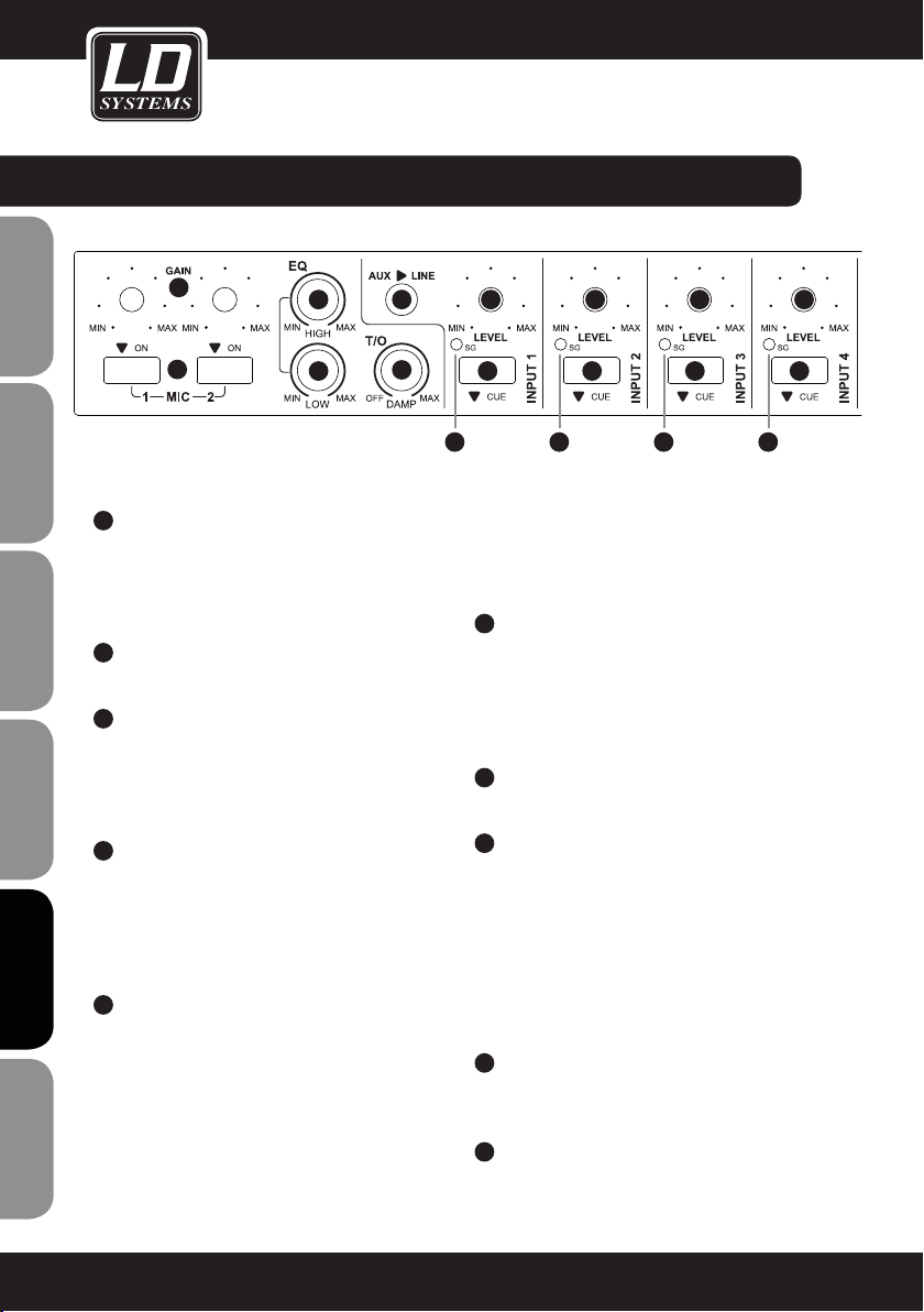
przYłącza, ELEMENTY OBSŁUGI I WSKAŹNIKI:
ENGLISHDEUTSCHFRANCAIS
1
2
3
ESpAñoLpoLSKIITALIANo
4
FRANCAISFRANCAIS FRANCAISFRANCAIS
5
2
1
3
4
6 7
5
MIC 1/2 ON
Włącznik/Wyłącznik dla kanałów mikrofonowych 1
i 2 ze zintegrowaną czerwoną diodą LED. W pozycji
wciśniętej kanał mikrofonowy jest włączony, a
dioda LED się świeci.
GAIN MIC 1/2
Regulator głośności dla kanałów mikrofonowych 1 i 2.
EQ HIGH MIC 1/2
Korektor tonów wysokich dla kanałów mikrofonowych
1 i 2. Obrót w lewo powoduje zmniejszenie poziomu
tonów wysokich, a obrót w prawo jego zwiększenie. W
pozycji środkowej (kliknięcie) korektor jest nieaktywny.
EQ LOW MIC 1/2
Korektor tonów niskich dla kanałów mikrofonowych
1 i 2. Obrót w lewo powoduje zmniejszenie poziomu
tonów niskich, a obrót w prawo jego zwiększenie.
W pozycji środkowej (kliknięcie) korektor jest
nieaktywny.
T/O DAMP
Funkcja talkover dla kanałów mikrofonowych 1 i
2. Regulator DAMP przekręcony w lewo do oporu
wyłącza funkcję talkover. Im bardziej regulator
DAMP zostanie przekręcony w prawo, tym bardziej
sygnały podawane na wejściach INPUT 1–5 oraz
FOH będą tłumione poprzez nadawany sygnał
mikrofonowy. Wartość progową ustawia się za
pomocą regulatora T/O LEVEL na tylnej ścianie
urządzenia (czułość, z jaką funkcja talkover reaguje
7
8
9
8
9
7
8
9
na podawany sygnał mikrofonowy). Funkcja talkover
nie jest dostępna dla wyjścia ZONE, gdy za pomocą
przełącznika SOURCE wybrano jedno ze źródeł sygnału
INPUT 1–5.
6
AUX/LINE
Liniowe wejście stereo z gniazdem jack 3,5 mm i
funkcją przełączania. Jeśli do tego gniazda zostanie
podłączona wtyczka jack 3,5 mm, wejścia cinch
kanału INPUT 1 na tylnej stronie urządzenia zostaną
wyłączone.
7
LEVEL INPUT 1–5 i FOH
Regulator głośności dla kanałów INPUT 1 do 5 i FOH.
8
CUE INPUT 1–5 i FOH
Przełącznik Cue ze zintegrowaną diodą LED
dla kanałów INPUT 1–5. Gdy przełącznik jest
wciśnięty (świeci się dioda LED), podawany sygnał
jest przekazywany do wyjścia słuchawkowego na
przedniej ścianie urządzenia. Przed regulatorem
głośności (LEVEL INPUT 1–5 i FOH) dla danego
kanału sygnał jest przejmowany, a zatem jest
niezależny od ustawienia regulatora głośności.
9
SG LED INPUT 1–5 i FOH
Dioda sygnalizacyjna świeci się na zielono, gdy na
wejściu danego kanału podawany jest sygnał audio.
10
MASTER EQ HIGH
Korektor tonów wysokich dla wyjścia MASTER.
Obrót w lewo powoduje zmniejszenie poziomu
7
8
9
78
Page 79
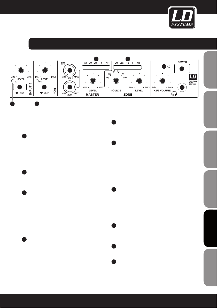
przYłącza, ELEMENTY OBSŁUGI I WSKAŹNIKI:
7
8
9
7
8
9
10
11
tonów wysokich, a obrót w prawo jego zwiększenie. W
pozycji środkowej (kliknięcie) korektor jest nieaktywny.
11
MASTER EQ LOW
Korektor tonów niskich dla wyjścia MASTER.
Obrót w lewo powoduje zmniejszenie poziomu
tonów niskich, a obrót w prawo jego zwiększenie.
W pozycji środkowej (kliknięcie) korektor jest
nieaktywny.
12
MASTER LEVEL
Regulator głośności dla wyjścia MASTER na tylnej
ścianie urządzenia.
13
MASTER AUDIO LEVEL METER
Wskaźnik miernika poziomu z 5 segmentami diod
LED. Jeżeli zaświeci się dioda peak (PK), oznacza
to, że urządzenie pracuje na granicy zniekształceń.
Krótkie zaświecenie się górnych poziomów
przekazywanego sygnału nie jest krytyczne,
należy jednak unikać trwałego świecenia się diod
poprzez redukcję głośności.
14
ZONE SOURCE
Wybór źródła sygnału, które ma zostać podłączone
do wyjścia strefowego. Można wybrać jeden z
5 kanałów wejściowych (IN 1–5) lub połączenie
(MIX) wszystkich kanałów wejściowych (MIC 1 i 2,
INPUT 1–5, FOH).
13
12
16
20
14
15
17
19
18
FRANCAISFRANCAIS FRANCAISFRANCAIS
15
ZONE LEVEL
Regulator głośności dla wyjścia strefowego (ZONE)
na tylnej ścianie urządzenia.
FRANCAISDEUTSCHENGLISH
16
ZONE AUDIO LEVEL METER
Wskaźnik miernika poziomu z 5 segmentami diod
LED. Jeżeli zaświeci się dioda peak (PK), oznacza
to, że urządzenie pracuje na granicy zniekształceń.
Krótkie zaświecenie się górnych poziomów
przekazywanego sygnału nie jest krytyczne,
należy jednak unikać trwałego świecenia się diod
poprzez redukcję głośności.
17
CUE VOLUME
Regulator głośności dla wyjścia słuchawkowego.
Kanały, dla których przycisk CUE jest wciśnięty
(INPUT 1–5, FOH), mogą być odsłuchiwane na
wyjściu słuchawkowym niezależnie od ustawienia
ich regulatora głośności.
18
WYJŚCIE SŁUCHAWKOWE
Wyjście słuchawkowe z gniazdem jack stereo
6,3 mm.
19
POWER
Włącznik/Wyłącznik urządzenia.
20
POWER LED
Zapala się, gdy urządzenie jest prawidłowo
podłączone do sieci elektrycznej i włączone.
ITALIANOPOLSKIESPAÑOL
79
Page 80

przYłącza, ELEMENTY OBSŁUGI I WSKAŹNIKI:
ENGLISHDEUTSCHFRANCAIS
21
22
ESpAñoLpoLSKIITALIANo
23
FRANCAISFRANCAIS FRANCAISFRANCAIS
24
23
21
22
GNIAZDO SIECIOWE IEC ZE ZINTEGROWANĄ
PODSTAWĄ BEZPIECZNIKA.
WAŻNE WSKAZÓWKI: PRZED włączeniem urządzenia
należy sprawdzić, czy napięcie sieciowe źródła
zasilania i napięcie robocze urządzenia są takie
same! Bezpiecznik należy wymieniać wyłącznie na
bezpiecznik tego samego typu i o takich samych
parametrach (nadruk na tylnej ścianie urządzenia)!
Jeśli bezpiecznik stale się przepala, należy
skontaktować się z autoryzowanym centrum
serwisowym.
T/O LEVEL
Wartość progową dla funkcji talkover ustawia się
za pomocą regulatora T/O LEVEL na tylnej ścianie
urządzenia (czułość, z jaką funkcja talkover reaguje
na podawany sygnał mikrofonowy). Funkcja talkover jest dostępna dla wyjść liniowych MASTER i
ZONE (przełącznik SOURCE w pozycji MIX).
MASTER MAX LEVEL
Maksymalny poziom podawany na wyjściu MASTER
należy ustawić przy użyciu odpowiedniego wkrętaka.
MASTER OUTPUT L/R UNBALANCED
Niesymetryczne wyjście stereo z gniazdami cinch
(lewe/prawe). Sygnał wyjścia MASTER składa się
z sumy sygnałów wejść MIC 1 i 2, INPUT 1 do 5
oraz FOH.
24 25
28
30
32
33
29
2627
25
MASTER OUTPUT L/R BALANCED
Symetryczne wyjście stereo z gniazdami jack 6,3
mm (lewe/prawe). Sygnał wyjścia MASTER składa
się z sumy sygnałów wejść MIC 1 i 2, INPUT 1 do
5 oraz FOH.
26
MASTER OUTPUT L/R BALANCED
Symetryczne wyjście stereo (lewe/prawe) z
przyłączem z blokiem zaciskowym (blok zaciskowy w
zestawie). Sygnał wyjścia MASTER składa się z sumy
sygnałów wejść MIC 1 i 2, INPUT 1 do 5 oraz FOH.
27
EMERGENCY INPUT
Symetryczne przyłącze z blokiem zaciskowym
dla akustycznego systemu awaryjnego (blok
zaciskowy w zestawie). Gdy podawany jest
sygnał audio z poziomem liniowym, wszystkie
wejścia mikrofonowe i wejściowe są wyciszane,
a sygnał awaryjny przełączany jest bezpośrednio
na wyjścia liniowe MASTER i ZONE. Regulatory
głośności kanałów MASTER i ZONE są nieaktywne.
28
EMERGENCY INPUT LEVEL
Głośność sygnału awaryjnego należy ustawić przy
użyciu odpowiedniego wkrętaka.
29
OUTPUT MUTE
Przyłącze z blokiem zaciskowym do podłączania
styku bezpotencjałowego lub przełącznika MUTE
(blok zaciskowy w zestawie). Gdy obwód jest
zamknięty, wszystkie kanały wejściowe oprócz
EMERGENCY INPUT są wyciszone.
31
34
35 36
80
Page 81

przYłącza, ELEMENTY OBSŁUGI I WSKAŹNIKI:
38
37
45
30
ZONE OUTPUT BALANCED
Symetryczne wyjście mono z gniazdem jack 6,3
mm. Sygnał wyjścia ZONE może składać się z sumy
sygnałów wejść MIC 1 i 2, INPUT 1 do 5 oraz FOH
(przełącznik ZONE SOURCE 14 na przedniej ścianie
urządzenia ustawić w pozycji MIX) lub obejmować
sygnał jednego z wejść INPUT 1 do 5 (przełącznik
ZONE SOURCE 14 na przedniej ścianie urządzenia
ustawić w pozycji jednego z wejść INPUT 1–5).
31
ZONE OUTPUT BALANCED
Symetryczne wyjście mono z przyłączem z
blokiem zaciskowym (blok zaciskowy w zestawie).
Sygnał wyjścia ZONE może składać się z sumy
sygnałów wejść MIC 1 i 2, INPUT 1 do 5 oraz
FOH (przełącznik ZONE SOURCE 14 na przedniej
ścianie urządzenia ustawić w pozycji MIX) lub
obejmować sygnał jednego z wejść INPUT 1 do
5 (przełącznik ZONE SOURCE 14 na przedniej
ścianie urządzenia ustawić w pozycji jednego z
wejść INPUT 1–5).
32
ZONE MAX LEVEL
Maksymalny poziom podawany na wyjściu ZONE
należy ustawić przy użyciu odpowiedniego wkrętaka.
33
ZONE EQ HIGH
Korektor tonów wysokich dla wyjścia ZONE. Obrót w
lewo powoduje zmniejszenie poziomu tonów wysokich, a obrót w prawo jego zwiększenie. W pozycji
środkowej (kliknięcie) korektor jest nieaktywny.
38
38
41 42
39
40
34
ZONE EQ LOW
Korektor tonów niskich dla wyjścia ZONE. Obrót
w lewo powoduje zmniejszenie poziomu tonów
niskich, a obrót w prawo jego zwiększenie. W pozycji
środkowej (kliknięcie) korektor jest nieaktywny.
35
REC OUTPUT L/R
Niesymetryczne liniowe wyjście stereo z gniazdami
cinch (lewe/prawe). Sygnał wyjścia REC składa się
z sumy sygnałów wejść MIC 1 i 2, INPUT 1–5 oraz
FOH. Poziom wyjściowy jest zależny od ustawienia
regulatora głośności dla wyjścia MASTER, a sygnał
jest przejmowany przed korektorem, jest zatem od
niego niezależny.
36
FOH INPUT L/R
Symetryczne liniowe wejście stereo z gniazdami
jack 6,3 mm (lewe/prawe). Możliwość podłączenia
urządzenia zewnętrznego (np. pulpitu mikserskiego).
37
LINE IN 3–5
Niesymetryczne liniowe wejścia stereo 3 do 5 z
gniazdami cinch (lewe/prawe).
38
TRIM 3–5
Aby dopasować podłączane urządzenia (odtwarzacz
CD, odtwarzacz MP3 itp.) o różnych poziomach
wyjściowych, należy ustawić przedwzmocnienie
kanałów INPUT 3 do 5 za pomocą odpowiedniego
wkrętaka.
W przypadku kanału 5 dotyczy to także sygnału
odtwarzanego z interfejsu USB.
41
39
42
40
4337 37
44
FRANCAISFRANCAIS FRANCAISFRANCAIS
FRANCAISDEUTSCHENGLISH
ITALIANOPOLSKIESPAÑOL
81
Page 82

przYłącza, ELEMENTY OBSŁUGI I WSKAŹNIKI:
39
ENGLISHDEUTSCHFRANCAIS
40
41
42
43
ESpAñoLpoLSKIITALIANo
LINE INPUT 1–2
Niesymetryczne liniowe wejścia stereo 1 i 2 z
gniazdami cinch (lewe/prawe).
MIC INPUT 1–2
Symetryczne wejścia mikrofonowe INPUT 1 i 2 z
gniazdem jack 6,3 mm. Te wejścia mikrofonowe
nie są wyposażone w zasilanie fantomowe.
PRZEŁĄCZNIK MIC INPUT 1–2
Gdy przełącznik jest wciśnięty, aktywne jest
wejście mikrofonowe danego kanału, a wejście
liniowe jest wyciszone.
TRIM INPUT 1–2
Włącznik 41 w pozycji niewciśniętej: aby dopasować
podłączane urządzenia (odtwarzacz CD, odtwarzacz
MP3 itp.) o różnych poziomach wyjściowych, należy
ustawić przedwzmocnienie kanałów INPUT 3 do 5 za
pomocą odpowiedniego wkrętaka.
Włącznik 41 w pozycji wciśniętej: przedwzmocnienie
dla wejścia mikrofonowego. Do regulacji należy użyć
odpowiedniego wkrętaka.
MIC 1–2
Symetryczne wejścia mikrofonowe 1 i 2 z
gniazdem jack 6,3 mm. Oba wejścia mikrofonowe
posiadają zasilanie fantomowe 12 V.
Sygnał nagrywania składa się z sygnału sumy i
jest przejmowany za regulatorem MASTER LEVEL i
regulatorem MAX LEVEL, jest zatem od nich zależny.
Odtwarzanie audio następuje poprzez kanał liniowy
INPUT 5. W tym celu należy wcisnąć przełącznik 45 na
tylnej ścianie urządzenia (USB).
45
USB/LINE
Przełącznik służący do wyboru źródła sygnału dla
kanału liniowego INPUT 5. W pozycji wciśniętej jako
źródło sygnału wybrany jest interfejs USB (44), a w
pozycji niewciśniętej wejście liniowe (37).
44
FRANCAISFRANCAIS FRANCAISFRANCAIS
82
USB
Interfejs USB (USB 1.1) umożliwia użycie pulpitu
mikserskiego jako interfejsu audio. Oznacza to, że
nagrywanie i odtwarzanie audio może następować
poprzez podłączony komputer z systemem
operacyjnym Windows (Windows XP, Vista, 7, 8) i
systemem operacyjnym Apple Macintosh od 10.5.
Do instalacji nie są potrzebne oddzielne sterowniki. Po podłączeniu do odpowiedniego interfejsu
USB w komputerze (USB 1.1, USB 2.0) sterowniki
instalowane są automatycznie, a interfejs audio
zostaje rozpoznany jako interfejs „USB Audio
CODEC” zarówno przez system Windows, jak i na
komputerach Apple Macintosh.
Page 83

FRANCAISFRANCAIS FRANCAISFRANCAIS
FRANCAISDEUTSCHENGLISH
ITALIANOPOLSKIESPAÑOL
83
Page 84

przYkłaD OKABLOWANIA:
ENGLISHDEUTSCHFRANCAIS
ESpAñoLpoLSKIITALIANo
FRANCAISFRANCAIS FRANCAISFRANCAIS
84
akustyczny system awaryjny
styk bezpotencjałowy/przełącznik MUTE
Page 85

przYkłaD OKABLOWANIA:
FRANCAISFRANCAIS FRANCAISFRANCAIS
FRANCAISDEUTSCHENGLISH
ITALIANOPOLSKIESPAÑOL
85
Page 86

SPECYFIKACJA:
Oznaczenie modelu: LDZONE622
Rodzaj produktu: mikser strefowy
ENGLISHDEUTSCHFRANCAIS
ESpAñoLpoLSKIITALIANo
FRANCAISFRANCAIS FRANCAISFRANCAIS
Typ: stereo
Kanały wejściowe łącznie: 8 (2 x Mic, 2 x Mic/Line, 3 x Line, 1 x FOH)
Charakterystyka częstotliwościowa: 20–40.000 Hz
Kanały mikrofonowe: 2, z zasilaniem fantomowym 12 V
Przyłącza kanałów mikrofonowych: jack 6,3 mm (symetryczne)
Elementy obsługi kanałów mikrofonowych: Gain, On/Off, 1 x EQ Hi, 1 x EQ Low, 1 x Talk Over
Wskaźniki kanałów mikrofonowych: On-LED
Impedancja wejściowa kanałów mikrofonowych: 4kΩ
Czułość wejściowa kanałów mikrofonowych: 6,1 mV
Współczynnik zniekształceń (THD) kanałów mikro-
fonowych:
Kanały liniowe, kanały mikrofonowe: 2
Przyłącza wejściowe kanałów liniowych/kanałów
mikrofonowych:
Elementy obsługi kanałów liniowych/kanałów
mikrofonowych:
Wskaźniki kanałów liniowych/kanałów mikrofo-
nowych:
Kanały liniowe: 3
Przyłącza wejściowe liniowe: 2 x cinch
Elementy obsługi kanałów liniowych: Level, Cue, Trim
Wskaźniki kanałów liniowych: Signal-LED, Cue-LED
Impedancja wejściowa kanałów liniowych: 4kΩ
Czułość wejściowa kanałów liniowych: 1,5 V
Współczynnik zniekształceń (THD) kanałów
liniowych:
Czułość wejściowa AUX/Line (jack stereo 3,5 mm): 3 V
Kanały FOH: 1
Przyłącza wejścia FOH: 2 x jack 6,3 mm symetryczne
Elementy obsługi kanałów FOH: Level, Cue
Damp, 1 x Talk Over Level
0,08%
2 x cinch, jack 6,3 mm (niesymetryczne), jack stereo
3,5 mm (Input 1)
Level, Cue, Mic/Line, Trim
Signal-LED, Cue-LED
0,03%
86
Page 87

SPECYFIKACJA:
Wskaźniki kanałów FOH: Signal-LED, Cue-LED
Wyjścia liniowe: 3 (Master – stereo, Zone – mono, Rec – stereo)
Przyłącza wyjściowe Master: 2 x jack 6,3 mm symetryczne, 2 x cinch, blok zaciskowy
Elementy obsługi Master: Level, EQ Hi, EQ Low, Max. Level
Wskaźniki Master: 5-segmentowy Level Master
Poziom wyjściowy Master: 24 dBu (symetryczny), 18 dBu (niesymetryczny)
Przyłącza wyjściowe Zone: jack 6,3 mm symetryczne, blok zaciskowy
Elementy obsługi Zone: Level, EQ Hi, EQ Low, Max. Level, Source Input 1–5/Mix
Wskaźniki Zone: 5-segmentowy Level Master
Poziom wyjściowy Zone: 24 dBu (symetryczny/niesymetryczny)
Przyłącza wyjściowe Rec: 2 x cinch
Wyjście słuchawkowe: 1
Przyłącze wyjścia słuchawkowego: jack stereo 6,3 mm
Elementy obsługi wyjścia słuchawkowego: Cue Volume
Napięcie wyjściowe wyjścia słuchawkowego: 1,25 V @ 32 Ω
Dodatkowe wejścia: 2 (Emergency Input, Output Mute)
Przyłącza dodatkowych wejść: blok zaciskowy
Elementy obsługi dodatkowych wejść: Level Emergency Input
Dodatkowe elementy obsługi: włącznik Power
Dodatkowe wskaźniki: dioda zasilania
Napięcie robocze: 220–250 V AC, 50 Hz
Przyłącze zasilania sieciowego: gniazdo urządzenia IEC
Pobór mocy (maks.): 18 W
Bezpiecznik: T 500 mAL/250 V
Wymiary (szer. x wys. x gł.): 485 x 44 x 179 mm
Waga: 2,44 kg
Akcesoria w zestawie: bloki zaciskowe, kabel sieciowy, instrukcja
Pozostałe cechy: interfejs USB 1.1 (kompatybilny z USB 2.0) do zastosowania
jako interfejs audio (16 bitów, nagrywanie i odtwarzanie).
Obsługiwane systemy operacyjne: Windows XP, Vista, 7, 8 i
Apple Macintosh od 10.5
FRANCAISFRANCAIS FRANCAISFRANCAIS
FRANCAISDEUTSCHENGLISH
ITALIANOPOLSKIESPAÑOL
87
Page 88

DEKLARACJE proDUcenta:
GWARANCJA PRODUCENTA
Niniejsza gwarancja dotyczy marek Adam Hall, LD Systems, Defender, Palmer i Cameo.
Obejmuje ona wszystkie marki znajdujące się w ofercie firmy Adam Hall.
ENGLISHDEUTSCHFRANCAIS
Niniejsze oświadczenie gwarancyjne nie ogranicza ustawowych roszczeń wobec producenta wynikających z
rękojmi, lecz rozszerza je o dodatkowe roszczenia gwarancyjne wobec firmy Adam Hall.
Adam Hall gwarantuje, że w okresie od dwóch do pięciu lat (w zależności od produktu) od daty zakupu dany produkt Adam Hall, który został zakupiony bezpośrednio od firmy Adam Hall lub od autoryzowanego sprzedawcy, pod
warunkiem zgodnego z przeznaczeniem użytkowania jest wolny od wad materiałowych i produkcyjnych.
Okres gwarancji rozpoczyna się od daty zakupu produktu, którą w razie wystąpienia przypadku objętego gwarancją
należy odpowiednio udokumentować (poprzez przedłożenie faktury lub dowodu dostawy z datą zakupu). Jeśli w
przypadku produktów wymienionych powyżej marek konieczna będzie naprawa w trakcie trwania okresu gwarancji, klient jest uprawniony do jej zlecenia w oparciu o niniejsze warunki.
W trakcie trwania okresu gwarancji firma Adam Hall naprawi lub wymieni wadliwe elementy lub produkty. W
przypadku naprawy lub wymiany w trakcie trwania okresu gwarancji wymienione części oryginalne lub produkty
stają się własnością firmy Adam Hall.
Jeśli nastąpi bardzo mało prawdopodobna sytuacja wielokrotnego występowania wady w nabytym przez klienta
produkcie, firma Adam Hall ma prawo, według własnego uznania, zastąpić wadliwy produkt, pod warunkiem, że
nowy produkt będzie co najmniej równoważny z wymienianym produktem pod względem specyfikacji technicznej.
Adam Hall nie udziela gwarancji na bezzakłóceniowe i/lub bezawaryjne działanie tego produktu. Adam Hall nie
ponosi także odpowiedzialności za szkody powstałe wskutek nieprzestrzegania instrukcji obsługi lub innych dokumentów załączonych do tego produktu firmy Adam Hall. Gwarancja producenta nie obejmuje – części zużywalnych
ESpAñoLpoLSKIITALIANo
(np. akumulatory), – produktów, z których usunięto numer seryjny lub które zostały uszkodzone w wyniku wypadku,
– szkód wynikających z nieodpowiedniej eksploatacji, nieprawidłowej obsługi lub innych przyczyn zewnętrznych,
– szkód w urządzeniach, które były eksploatowane niezgodnie z ich parametrami roboczymi (parametry zgodne z
dokumentacją załączoną do produktu),
– szkód wynikających ze stosowania części zamiennych, które nie są produkowane, sprzedawane lub zalecane
przez firmę Adam Hall,
– szkód wynikających z ingerencji osób trzecich/modyfikacji lub napraw, które nie zostały przeprowadzone przez
FRANCAISFRANCAIS FRANCAISFRANCAIS
firmę Adam Hall.
Niniejsze postanowienia i warunki stanowią kompletną i wyłączną umowę gwarancyjną między klientem a firmą
Adam Hall dotyczącą zakupionego przez klienta produktu Adam Hall.
88
Page 89

DEKLARACJE proDUcenta:
OGRANICZENIE ODPOWIEDZIALNOŚCI
Jeśli w produktach sprzętowych firmy Adam Hall w trakcie trwania okresu gwarancji wystąpią szkody
materiałowe lub technologiczne (zgodnie z powyższym oświadczeniem gwarancyjnym), jedyne i wyłączne
prawo klienta wynikające z niniejszej gwarancji dotyczy naprawy lub wymiany urządzenia. Maksymalna
odpowiedzialność firmy Adam Hall jest zgodnie z niniejszą gwarancją wyraźnie ograniczona do ceny kupna lub
kosztów naprawy lub wymiany (w zależności od tego, która z tych kwot będzie niższa) elementów uszkodzonych
podczas normalnego użytkowania.
Adam Hall nie ponosi odpowiedzialności za żadne szkody spowodowane przez produkt lub jego nieprawidłowe
działanie, włącznie z utraconym zyskiem i niepowstałymi oszczędnościami oraz szkodami szczególnymi,
pośrednimi i wynikowymi. Ponadto Adam Hall nie ponosi odpowiedzialności za roszczenia prawne osób trzecich
ani roszczenia zgłoszone przez klienta w imieniu osób trzecich.
Niniejsze ograniczenie odpowiedzialności obowiązuje niezależnie od tego, czy szkody są dochodzone na drodze
sądowej lub czy roszczenia odszkodowawcze wnoszone są w ramach niniejszej gwarancji w wyniku niedozwolonych działań (włącznie z niedbalstwem i odpowiedzialnością z tytułu zagrożenia) lub w wyniku roszczeń
umownych lub innych. Nie może ono zostać także przez nikogo zniesione ani zmienione. Niniejsze ograniczenie
odpowiedzialności obowiązuje także wówczas, gdy klient poinformuje firmę Adam Hall lub autoryzowanego
przedstawiciela firmy Adam Hall o możliwości wystąpienia takich szkód, nie obowiązuje natomiast w przypadku
roszczeń odszkodowawczych związanych ze szkodami na osobie.
Niniejsza gwarancja producenta przyznaje klientowi określone prawa. W zależności od jurysdykcji (państwo lub
kraj związkowy) klientowi może przysługiwać prawo zgłoszenia dalszych roszczeń. W takich przypadkach zaleca
się zastosowanie odpowiednich przepisów umożliwiających skorzystanie z pełni przysługujących danej osobie
praw.
FRANCAISFRANCAIS FRANCAISFRANCAIS
FRANCAISDEUTSCHENGLISH
SKORZYSTANIE Z GWARANCJI
W razie wystąpienia przypadku objętego gwarancją należy zwrócić się bezpośrednio do firmy Adam Hall lub do
autoryzowanego sprzedawcy, u którego produkt został zakupiony.
DekLaracJa ZGODNOŚCI WE
Sprzedawane przez firmę Adam Hall urządzenia są zgodne z podstawowymi wymogami i pozostałymi
obowiązującymi specyfikacjami określonymi dyrektywami 1999/5/WE (R&TTE), 2004/108/WE (EMC) i 2006/95/
WE (LVD) (o ile mają zastosowanie). Dalsze informacje dostępne są na stronie www.adamhall.com.
ITALIANOPOLSKIESPAÑOL
89
Page 90
DEKLARACJE proDUcenta:
PRAWIDŁOWA UTYLIZACJA NINIEJSZEGO PRODUKTU
(dotyczy Unii Europejskiej i innych krajów europejskich, w których stosuje się segregację odpadów)
Niniejszy symbol na produkcie lub związanych z nim dokumentach wskazuje, iż po zakończeniu okresu
ENGLISHDEUTSCHFRANCAIS
użytkowania urządzenie nie może być utylizowane razem ze standardowymi odpadami domowymi, ponieważ
mogłoby to spowodować szkody w środowisku lub szkody na osobie powstałe w wyniku niekontrolowanego
usuwania odpadów. Niniejszy produkt należy utylizować oddzielnie od innych odpadów i przekazać do punktu
recyklingu w celu wspierania ruchu okrężnego w gospodarce w ramach idei zrównoważonego rozwoju.
Klienci prywatni otrzymują informacje w zakresie przyjaznych dla środowiska możliwości usuwania odpadów od
sprzedawcy, u którego produkt został zakupiony, lub w odpowiednich placówkach regionalnych.
Użytkownicy będący przedsiębiorcami proszeni są o kontakt ze swoimi dostawcami i ewentualne sprawdzenie
uzgodnionych umownie warunków utylizacji urządzeń. Niniejszy produkt nie może być utylizowany razem z
innymi odpadami przemysłowymi.
OCHRONA ŚRODOWISKA i oSzczĘDzanie enerGii
Oszczędzanie energii stanowi aktywny wkład w ochronę środowiska. Należy wyłączać wszystkie nieużywane
urządzenia elektryczne. Aby zapobiec zużywaniu prądu przez nieużywane urządzenia znajdujące się w trybie
czuwania (standby), należy wyjąć wtyczkę z gniazda sieciowego.
ESpAñoLpoLSKIITALIANo
FRANCAISFRANCAIS FRANCAISFRANCAIS
Adam Hall GmbH, wszystkie prawa zastrzeżone. Dane techniczne i funkcjonalne produktu mogą podlegać
modyfikacjom. Kopiowanie, tłumaczenie i pozostałe formy reprodukcji fragmentów lub całości tej instrukcji
obsługi są zabronione.
90
Page 91

FRANCAISFRANCAIS FRANCAISFRANCAIS
FRANCAISDEUTSCHENGLISH
ITALIANOPOLSKIESPAÑOL
91
Page 92

ENGLISHDEUTSCHFRANCAIS
Avete fatto la scelta giusta!
Quest‘apparecchio è stato sviluppato e prodotto secondo elevati standard qualitativi che garantiscono un funzionamento regolare per molti anni. Per questo motivo LD Systems, con il suo nome e la pluriennale esperienza,
rappresenta un‘azienda produttrice di prodotti audio di qualità.
Leggete attentamente questo manuale d‘uso per utilizzare al meglio il vostro nuovo prodotto LD Systems.
Per maggiori informazioni su LD SYSTEMS, consultate la nostra pagina web WWW.LD-SYSTEMS.COM
Introduzione
Il dispositivo ZONE 622 è un mixer a zone particolarmente compatto, con altezza 1U, provvisto di 6canali
ESpAñoLpoLSKIITALIANo
di linea e 2canali microfono che è possibile assegnare a un'uscita principale stereo e a un'uscita principale
mono. Il dispositivo dispone di tutte le funzioni fondamentali, di un ingresso per un sistema di comunicazione di
emergenza esterno con regolatore di volume proprio nonché di un collegamento con la modalità di silenziamento
telecomandata. Il ZONE 622 è ideale per sonorizzare zone distinte in ristoranti, club, hotel, centri fitness e per
presentazioni.
FRANCAISFRANCAIS FRANCAISFRANCAIS
92
Page 93

MIXER a 2 zone per rack
LDzONE622
FRANCAISFRANCAIS FRANCAISFRANCAIS
FRANCAISDEUTSCHENGLISH
ITALIANOPOLSKIESPAÑOL
93
Page 94
miSUre PRECAUZIONALI:
1. Leggere attentamente il presente manuale di istruzioni.
2. Conservare tutte le indicazioni e le istruzioni in un luogo sicuro.
3. Seguire le istruzioni.
4. Rispettare tutte le avvertenze. Non rimuovere dal dispositivo le indicazioni sulla sicurezza o altre informazioni.
5. Utilizzare il dispositivo solo nei modi previsti dal manuale.
ENGLISHDEUTSCHFRANCAIS
6. Utilizzare esclusivamente stativi e fissaggi stabili e adatti (per installazioni fisse). Verificare che i supporti a parete
siano installati e fissati a regola d‘arte. Verificare che il dispositivo sia installato in modo stabile e non possa cadere.
7. Durante l‘installazione, osservare le normative sulla sicurezza in vigore nel proprio Paese.
8. Non installare né azionare il dispositivo in prossimità di radiatori, accumulatori termici, stufe o altre fonti di calore. Accertarsi che il dispositivo sia sempre installato in modo che venga raffreddato a sufficienza e non possa surriscaldarsi.
9. Non appoggiare sul dispositivo fonti di combustione, quali candele accese.
10. Le fessure di areazione non devono essere bloccate.
11. Non attivare il dispositivo nelle immediate vicinanze di acqua (questo punto non interessa i dispositivi specifici per l‘esterno, per i quali valgono le speciali indicazioni riportate di seguito). Non portare mai il dispositivo a
contatto con materiali, liquidi o gas infiammabili.
12. Accertarsi che all‘interno del dispositivo non possa penetrare acqua per gocciolamento o spruzzo. Non collocare sul dispositivo oggetti contenenti liquidi, quali vasi, tazze o bicchieri.
13. Assicurarsi che non sia possibile la caduta di oggetti nel dispositivo.
14. Azionare il dispositivo esclusivamente con gli accessori appositamente consigliati e previsti dal produttore.
15. Non aprire né modificare il dispositivo.
16. Una volta collegato il dispositivo, verificare tutti i cavi per evitare danni o incidenti, ad esempio per inciampo.
17. Durante il trasporto, assicurarsi che il dispositivo non possa cadere e causare possibili danni a cose e/o persone.
18. Se il dispositivo non funzionasse più correttamente, vi fosse caduto sopra del liquido o un oggetto o fosse
stato danneggiato in altro modo, spegnerlo immediatamente e staccare la spina (se si tratta di un dispositivo
attivo). La riparazione del dispositivo deve essere affidata esclusivamente a personale qualificato autorizzato.
19. Per la pulizia del dispositivo utilizzare un panno pulito.
20. Rispettare le leggi sullo smaltimento in vigore nel Paese di installazione. Al momento di smaltire l‘imballo,
separare la plastica dalla carta e dal cartone.
ESpAñoLpoLSKIITALIANo
21. I sacchetti di plastica devono essere tenuti lontani dalla portata dei bambini.
DISPOSITIVI CON ALLACCIAMENTO DI RETE:
22. ATTENZIONE: se il cavo di rete è dotato di contatto di protezione, deve essere collegato a una presa di rete
con messa a terra. Non disattivare mai la connessione di messa a terra di un cavo di rete.
23. Non accendere il dispositivo subito dopo essere stato sottoposto a forti variazioni di temperatura (ad esempio
dopo il trasporto). Umidità e condensa potrebbero danneggiare il dispositivo. Accendere il dispositivo solo dopo
FRANCAISFRANCAIS FRANCAISFRANCAIS
che ha raggiunto la temperatura ambiente.
24. Prima di collegare il dispositivo alla presa, controllare innanzitutto se la tensione e la frequenza della rete
elettrica coincidono con i valori indicati sul dispositivo stesso. Nel caso di dispositivo munito di selettore di
tensione, collegarlo alla presa unicamente se i valori del dispositivo coincidono con quelli della rete elettrica. Se il
cavo di rete o l‘adattatore di rete forniti in dotazione non sono compatibili con la presa, rivolgersi a un elettricista.
25. Non calpestare il cavo di rete. Accertarsi che i cavi sotto tensione, in particolare della presa di rete o
dell‘adattatore di rete, non vengano pizzicati.
26. Durante il cablaggio del dispositivo, verificare sempre che il cavo di rete e l‘adattatore di rete siano costantemente accessibili. Staccare sempre il dispositivo dall‘alimentazione di rete quando non è utilizzato o durante la
pulizia. Per staccare dalla presa il cavo di rete e l‘adattatore di rete, tirare sempre dalla spina o dall‘adattatore e
non dal cavo. Non toccare mai il cavo di alimentazione e l’alimentatore con le mani umide.
94
Page 95

SICUREZZA:
27. Evitare per quanto possibile di accendere e spegnere velocemente il dispositivo per non pregiudicarne la durata.
28. NOTA IMPORTANTE: Sostituire i fusibili esclusivamente con fusibili dello stesso tipo e valore. Se un fusibile
continua a saltare, rivolgersi a un centro di assistenza autorizzato.
29. Per staccare completamente il dispositivo dalla rete elettrica, rimuovere il cavo di rete o l‘adattatore di rete dalla presa.
30. Per staccare un dispositivo provvisto di presa Volex, è prima necessario sbloccare la relativa spina Volex del
dispositivo stesso. Tirando il cavo di rete, però, il dispositivo potrebbe spostarsi e cadere, provocando danni alle
persone o di altro genere. Prestare quindi la più scrupolosa attenzione durante la posa dei cavi.
31. In caso di pericolo di caduta di fulmine, o se il dispositivo rimane inutilizzato a lungo, staccare sempre il cavo
di rete e l‘adattatore di rete dalla presa.
CAUTION
RISK OF ELECTRIC SHOCK
DO NOT OPEN
ATTENZIONE:
non togliere mai il coperchio di protezione per evitare il pericolo di scosse elettriche. L’interno del dispositivo
non contiene parti che possono essere riparate o sottoposte a manutenzione da parte dell’utente. Le riparazioni
dovranno essere realizzate esclusivamente da tecnici qualificati.
Il triangolo isoscele con il simbolo del fulmine indica la presenza nel dispositivo di tensioni non
isolate, “pericolose”, che possono provocare scosse dannose alla salute.
Il triangolo isoscele con punto esclamativo avverte di importanti
segnalazioni relative all’uso e alla manutenzione.
ATTENZIONE: ELEVATI LIVELLI SONORI NEI PRODOTTI AUDIO!
Questo dispositivo è destinato a uso professionale. Di conseguenza, se viene destinato ad un uso commerciale,
sarà soggetto alle norme e ai regolamenti dell’Associazione per la prevenzione di infortuni del rispettivo settore
professionale. In qualità di produttore, Adam Hall è tenuto per legge a informare espressamente gli utenti degli
eventuali rischi per la salute.
Danni all’udito provocati da un’esposizione prolungata a un livello SPL elevato: dall’utilizzo di questo prodotto si
possono generare elevati livelli di pressione sonora (SPL) che possono provocare danni irreparabili all’udito di
artisti, collaboratori e spettatori. Evitare l’esposizione prolungata a livelli sonori elevati, superiori a 90 dB.
FRANCAISFRANCAIS FRANCAISFRANCAIS
FRANCAISDEUTSCHENGLISH
ATTENZIONE! INDICAZIONI IMPORTANTI RELATIVE AI PRODOTTI DI ILLUMINAZIONE
1. Non guardare il fascio di luce da distanze inferiori a 40 cm.
2. Non guardare mai a lungo il fascio di luce da breve-media distanza.
3. Non guardare mai il fascio di luce con dispositivi ottici quali le lenti d’ingrandimento.
4. In alcuni casi, in persone sensibili gli effetti stroboscopici possono causare attacchi epilettici. Pertanto, le
persone affette da epilessia devono assolutamente evitare luoghi in cui vengono impiegati effetti stroboscopici.
NOTA: in caso di installazione su rack, assicurarsi che la ventilazione sia sufficiente sopra e sotto l'apparecchio.
ITALIANOPOLSKIESPAÑOL
95
Page 96

conneSSioni, DISPOSITIVI E VISUALIZZAZIONE:
ENGLISHDEUTSCHFRANCAIS
1
2
3
ESpAñoLpoLSKIITALIANo
4
FRANCAISFRANCAIS FRANCAISFRANCAIS
5
2
1
3
4
6 7
5
MIC 1 / 2 ON
Interruttore di accensione/spegnimento per i canali
microfono 1 e 2 con LED rosso integrato. Quando
l'interruttore è premuto, il canale microfono è attivo
e il LED è illuminato.
GAIN MIC 1/2
Regolatore di volume audio per i canali microfono
1 e 2.
EQ HIGH MIC 1/2
Equalizzatore acuti per i canali microfono 1 e
2. Ruotare a sinistra per abbassare gli acuti e a
destra per alzarli. In posizione intermedia (si sente
un clic), l'equalizzatore è disattivato.
EQ LOW MIC 1/2
Equalizzatore bassi per i canali microfono 1 e 2.
Ruotare a sinistra per abbassare i bassi e a destra
per alzarli. In posizione intermedia (si sente un
clic), l'equalizzatore è disattivato.
T/O DAMP
Funzione Talkover per i canali microfono 1 e 2. Il
regolatore DAMP completamente ruotato a sinistra
disattiva la funziona Talkover. Mano a mano che
si gira il regolatore verso destra, i segnali degli
ingressi INPUT1 - 5 e FOH si riducono per consentire
l'ingresso di un segnale microfono sempre più forte.
Il valore soglia si imposta con il regolatore T/O LEVEL
presente sul pannello posteriore (sensibilità con cui
7
8
9
8
9
7
8
9
9
la funzione Talkover reagisce al segnale microfono in entrata). Se si è selezionata una delle fonti di segnale IN1 5 con il selettore ZONE SOURCE, la funzione Talkover non
è disponibile per l'uscita ZONE.
6
AUX/LINE
Ingresso linea stereo con presa jack da 3,5mm
e funzione di commutazione. Se questa presa
viene collegata con una spina jack da 3,5mm, gli
ingressi RCA del canale IN1 sul pannello posteriore
del dispositivo vengono disattivati.
7
LEVEL (INPUT 1 - 5 e FOH)
Regolatore di volume audio per i canali INPUT da
1 a 5 e FOH.
8
CUE (INPUT 1 - 5 e FOH)
Pulsante CUE con LED integrato per i canali INPUT1
- 5. Con il pulsante premuto (LED acceso), il segnale
presente viene inviato all'uscita delle cuffie che
si trova sul pannello frontale dell'apparecchio. Il
segnale viene rilevato davanti al regolatore di volume
audio (LIVELLO INPUT1 - 5 e FOH) del rispettivo
canale ed è quindi indipendente dall'impostazione
del regolatore stesso.
9
LED DI SEGNALE SG (INPUT 1 - 5 e FOH)
Il LED di segnale si accende in verde non appena
sull'ingresso del rispettivo canale appare un
segnale audio.
7
8
96
Page 97

conneSSioni, DISPOSITIVI E VISUALIZZAZIONE:
13
7
8
9
10
EQ HIGH (MASTER)
7
8
9
10
12
11
Equalizzatore acuti per uscita MASTER. Ruotare
a sinistra per abbassare gli acuti e a destra per
alzarli. In posizione intermedia (si sente un clic),
l'equalizzatore è disattivato.
16
20
14
15
LEVEL (ZONE)
15
17
Regolatore del volume per l'uscita a zone (ZONE)
sul pannello posteriore del dispositivo.
16
INDICATORE DEL LIVELLO DI ZONA
19
18
FRANCAISFRANCAIS FRANCAISFRANCAIS
FRANCAISDEUTSCHENGLISH
Visualizzazione dell'indicatore di livello (LEVEL
11
EQ LOW (MASTER)
Equalizzatore bassi per uscita MASTER. Ruotare
a sinistra per abbassare i bassi e a destra per
alzarli. In posizione intermedia (si sente un clic),
l'equalizzatore è disattivato.
METER) con 5segmenti LED. Non appena il LED
Peak (PK) si accende, l'apparecchio funziona al
limite di distorsione. Una breve accensione in
caso di picchi di livello del segnale presente non
è critica, ma si deve evitare l'accensione continua
riducendo il volume.
12
LEVEL (MASTER)
Regolatore del volume per l'uscita MASTER sul
pannello posteriore del dispositivo.
17
CUE VOLUME
Regolatore di volume audio per l'uscita cuffie. I canali
di cui si premono le manopole CUE (INPUT1 - 5 e
13
INDICATORE DEL LIVELLO MASTER
Visualizzazione dell'indicatore di livello (LEVEL
METER) con 5segmenti LED. Non appena il LED
FOH) possono essere esclusi indipendentemente
dall'impostazione del rispettivo regolatore di volume
sull'uscita delle cuffie.
Peak (PK) si accende, l'apparecchio funziona al
limite di distorsione. Una breve accensione in
caso di picchi di livello del segnale presente non
18
USCITA CUFFIE
Uscita cuffie con presa jack stereo da 6,3mm.
è critica, ma si deve evitare l'accensione continua
riducendo il volume.
14
SOURCE (ZONE)
19
POWER
Interruttore di accensione/spegnimento
dell'apparecchio.
ITALIANOPOLSKIESPAÑOL
Selezione della fonte di segnale che deve essere
attivata sull'uscita zone. In alternativa è possibile
scegliere uno dei 5canali di ingresso (IN1 - 5) o
un mix (MIX) tra tutti i canali di ingresso (MIC1 e
20
LED POWER
Si accende non appena il dispositivo viene corretta-
mente connesso alla rete elettrica e acceso.
2, INPUT1 - 5, FOH).
97
Page 98

conneSSioni, DISPOSITIVI E VISUALIZZAZIONE:
ENGLISHDEUTSCHFRANCAIS
21
22
ESpAñoLpoLSKIITALIANo
23
FRANCAISFRANCAIS FRANCAISFRANCAIS
23
21
22
PRESA DI RETE IEC CON PORTAFUSIBILE
INTEGRATO
NOTE IMPORTANTI: PRIMA della messa in funzione
assicurarsi che la tensione di rete dell'alimentatore
elettrico e la tensione di esercizio del dispositivo
coincidano! Sostituire il fusibile unicamente con un
fusibile dello stesso tipo e con gli stessi valori (v.
indicazione stampata sul retro)! Se il fusibile continua
a saltare, rivolgersi a un centro di assistenza
autorizzato.
T/O LEVEL
Il valore di soglia Talkover viene impostato con
il regolatore T/O LEVEL (sensibilità con cui la
funzione Talkover reagisce al segnale microfono
presente). La funzione Talkover è disponibile per le
uscite di linea MASTER e ZONE (selettore SOURCE
in posizione MIX).
MAX LEVEL (MASTER)
Regolare il livello massimo che deve essere
presente sull'uscita MASTER con un cacciavite
adatto.
24 25
28
30
32
33
29
2627
25
USCITA MASTER L/R BILANCIATA
Ingresso stereo bilanciato con prese jack da
6,3mm (sinistra/destra). Il segnale dell'uscita
MASTER è costituito dalla somma dei segnali degli
ingressi MIC1 e 2, INPUTda 1 a 5 e FOH.
26
USCITA MASTER L/R BILANCIATA
Uscita stereo bilanciata (sinistra/destra) con
collegamento al blocco morsetti (blocco morsetti
in dotazione). Il segnale dell'uscita MASTER è
costituito dalla somma dei segnali degli ingressi
MIC1 e 2, INPUTda 1 a 5 e FOH.
27
EMERGENCY INPUT
Collegamento bilanciato al blocco morsetti per un
sistema acustico di emergenza (blocco morsetti
incluso nella dotazione). Non appena è presente
un segnale audio con livello linea, tutti gli ingressi
di microfono e linea vengono portati in posizione
di silenzio e il segnale di emergenza viene attivato
direttamente sulle uscite di linea MASTER E ZONE.
I regolatori di volume audio dei canali MASTER e
ZONE sono ora disattivati.
31
34
35 36
98
24
USCITA MASTER L/R NON BILANCIATA
Uscita stereo non bilanciata con prese RCA
(sinistra/destra). Il segnale dell'uscita MASTER è
costituito dalla somma dei segnali degli ingressi
MIC1 e 2, INPUTda 1 a 5 e FOH.
28
LEVEL (EMERGENCY INPUT)
Regolare il volume del segnale di emergenza
utilizzando u n cacciavite adatto.
Page 99

conneSSioni, DISPOSITIVI E VISUALIZZAZIONE:
38
37
45
29
OUTPUT MUTE
Collegamento al blocco morsetti per collegare un
contatto privo di potenziale o di un interruttore
mute (blocco morsetti in dotazione). Con il contatto
chiuso, vengono silenziati tutti i canali di ingresso
eccetto EMERGENCY INPUT.
30
ZONE OUTPUT BILANCIATA
Uscita mono bilanciata con presa jack da 6,3mm.
Il segnale dell'uscita ZONE può essere formato
dalla somma dei segnali degli ingressi MIC1 e 2,
INPUTda 1 a 5 e FOH (posizionare su MIX il selettore
ZONE SOURCE14 presente sul pannello frontale
dell'apparecchio), oppure può contenere il segnale
di uno degli ingressi INPUT da 1 a 5 (posizionare il
selettore ZONE SOURCE14 presente sul pannello
frontale dell'apparecchio su uno degli ingressi IN da
1 a 5).
31
ZONE OUTPUT BILANCIATA
Uscita mono bilanciata con collegamento al blocco
morsetti (blocco morsetti in dotazione). Il segnale
dell'uscita ZONE può essere formato dalla somma
dei segnali degli ingressi MIC1 e 2, INPUTda
1 a 5 e FOH (posizionare su MIX il selettore
ZONE SOURCE14 presente sul pannello frontale
dell'apparecchio), oppure può contenere il segnale
di uno degli ingressi INPUT da 1 a 5 (posizionare il
selettore ZONE SOURCE14 presente sul pannello
frontale dell'apparecchio su uno degli ingressi IN
da 1 a 5).
38
38
41 42
39
40
32
MAX LEVEL (ZONE)
Utilizzando un cacciavite idoneo, regolare il livello
massimo che deve essere presente sull'uscita
ZONE.
33
EQ HIGH (ZONE)
Equalizzatore acuti per uscita ZONE. Ruotare a
sinistra per abbassare gli acuti e a destra per
alzarli. In posizione intermedia (si sente un clic),
l'equalizzatore è disattivato.
34
EQ LOW (ZONE)
Equalizzatore bassi per uscita ZONE. Ruotare
a sinistra per abbassare i bassi e a destra per
alzarli. In posizione intermedia (si sente un clic),
l'equalizzatore è disattivato.
35
USCITA REGISTRAZIONE (L/R)
Uscita linea stereo non bilanciata con prese RCA
(sinistra/destra). Il segnale dell'uscita REC è
costituito dalla somma dei segnali degli ingressi
MIC1 e 2, INPUTda 1 a 5 e FOH. Il livello di
uscita dipende dall'impostazione del regolatore di
volume audio dell'uscita MASTER; il segnale viene
rilevato davanti all'equalizzatore e pertanto non
viene elaborato.
36
FOH INPUT L/R
Ingresso linea stereo bilanciata con prese jack da
6,3mm (sinistra/destra). È possibile connettere un
dispositivo di riproduzione (ad es. il mixer).
41
39
42
40
4337 37
44
FRANCAISFRANCAIS FRANCAISFRANCAIS
FRANCAISDEUTSCHENGLISH
ITALIANOPOLSKIESPAÑOL
99
Page 100

conneSSioni, DISPOSITIVI E VISUALIZZAZIONE:
37
ENGLISHDEUTSCHFRANCAIS
38
39
40
41
ESpAñoLpoLSKIITALIANo
42
FRANCAISFRANCAIS FRANCAISFRANCAIS
LINE IN 3 - 5
Ingressi linea stereo non bilanciati da 3 a 5 con
prese RCA (sinistra/destra).
TRIM 3 - 5
Per adattare dispositivi di riproduzione (lettori CD,
lettori MP3 o simili) con diversi livelli di uscita,
impostare la preamplificazione dei canali3 - 5
utilizzando un cacciavite adatto.
Sul canale5 vale anche per il segnale di riproduzione
dell'interfaccia USB.
LINE INPUT 1 - 2
Ingressi linea stereo non bilanciati da 1 a 2 con
prese RCA (sinistra/destra).
MIC (INPUT 1 - 2)
Ingressi microfono bilanciati INPUT1 e 2 con
presa jack da 6,3mm. Questi ingressi microfono
non dispongono di alimentazione phantom.
INTERRUTTORE MIC INPUT 1 - 2
In posizione premuta, l'ingresso microfono del
relativo canale è attivo e l'ingresso di linea è
silenziato.
TRIM (INPUT 1 - 2)
Interruttore41 non premuto: Per adattare
dispositivi di riproduzione (lettori CD, lettori MP3
o simili) con diversi livelli di uscita, impostare la
preamplificazione dei canali3 - 5 utilizzando un
cacciavite adatto.
Interruttore41 premuto: preamplificazione per
l'ingresso del microfono. Eseguire l'impostazione
utilizzando un cacciavite adatto.
44
USB
L'interfaccia USB (USB1.1) permette di usare il
mixer come interfaccia audio. Ciò significa che
le registrazioni e le riproduzioni audio possono
essere effettuate da un computer connesso con
sistema operativo Windows (Windows XP, Vista, 7,
8) e Apple Macintosh da 10.5. Per l'installazione
non sono necessari driver esterni. Una volta
effettuato il collegamento al computer tramite
un'interfaccia USB idonea (USB1.1, USB2.0), i
driver si installano automaticamente e l'interfaccia
audio viene riconosciuta come interfaccia "USB
Audio CODEC" sia su computer Windows che
Apple Macintosh.
Il segnale di registrazione è formato dalla somma
dei segnali e viene rilevato dietro il regolatore
Master Level e dietro il regolatore Max Level, dai
quali pertanto è indipendente. La riproduzione
audio avviene attraverso l'ingresso INPUT5 del
canale di linea. A tal fine l'interruttore45 sul
pannello posteriore deve essere premuto (USB).
45
USB / LINE
Interruttore che consente di selezionare la fonte
del segnale per l'ingresso INPUT5 del canale di
linea. Se l'interruttore è premuto, come fonte del
segnale viene selezionata l'interfaccia USB (44),
altrimenti viene selezionato l'ingresso di linea (37).
100
43
MIC 1 - 2
Ingressi microfono bilanciati1 e 2 con presa
jack da 6,3mm. Entrambi gli ingressi microfono
dispongono di un'alimentazione phantom da 12V.
 Loading...