

Page 1
USER´S MANUAL
BEDIENUNGSANLEITUNG
MANUEL D`UTILISATION
MANUAL DE USUARIO
INSTRUKCJA OBSŁUGI
MANUALE D‘ USO
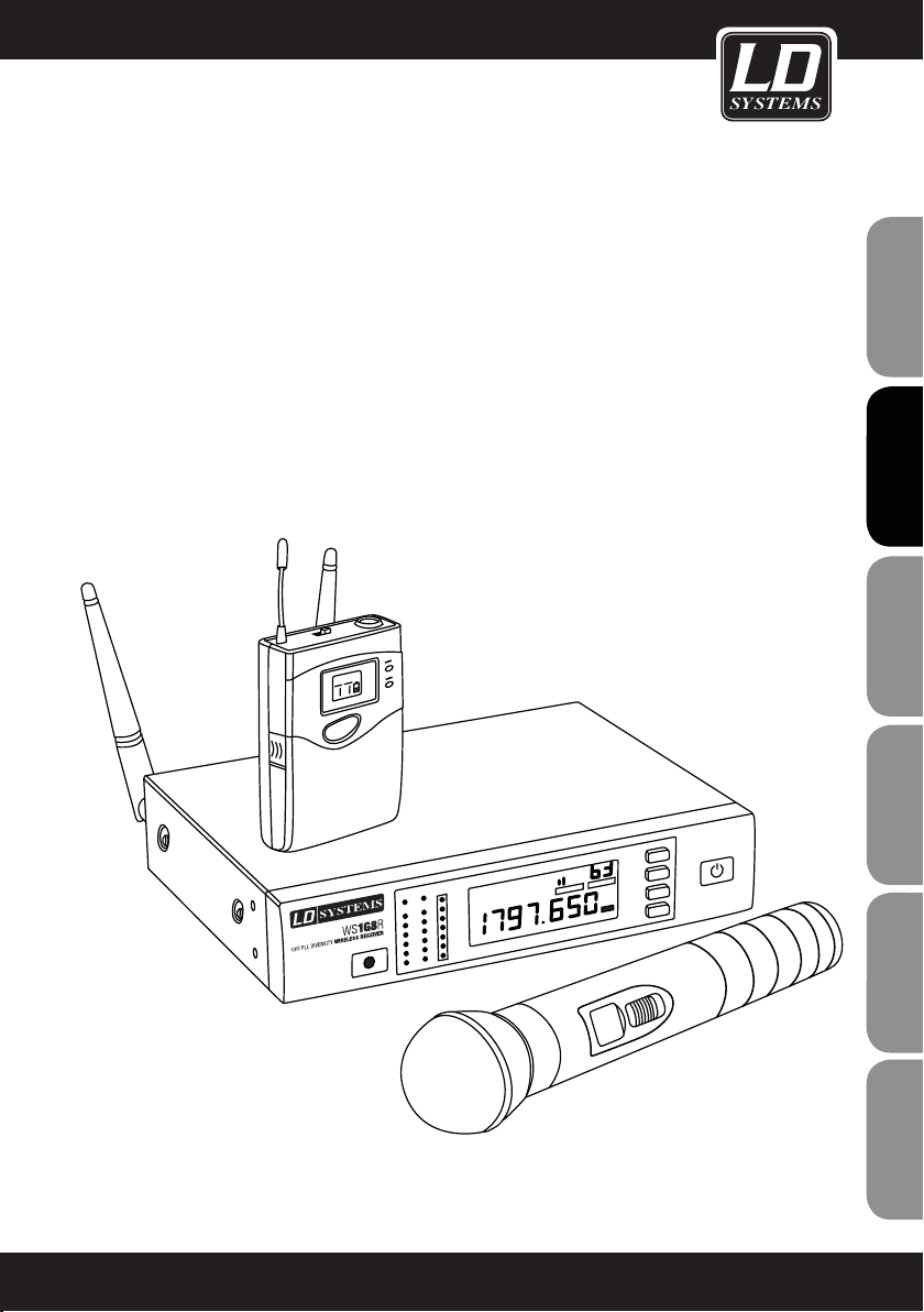
LD WS1G8
192 CHANNEL UHF TRUE DIVERSITY WIRELESS SYSTEM
Page 2
ENGLISHDEUTSCHFRANCAIS
Thank you for choosing LD Systems!
We have designed this product to operate reliably over many years. Therefore LD Systems guarantees for high
quality products with its name and many years of experience as a producer.
Please take a few moments to read these instructions carefully, as we want you to enjoy your new LD Systems
products quickly and to the fullest.
For information about LD Systems check out our website WWW.LD-SYSTEMS.COM
Introduction
ESpAñoLpoLSKIITALIANo
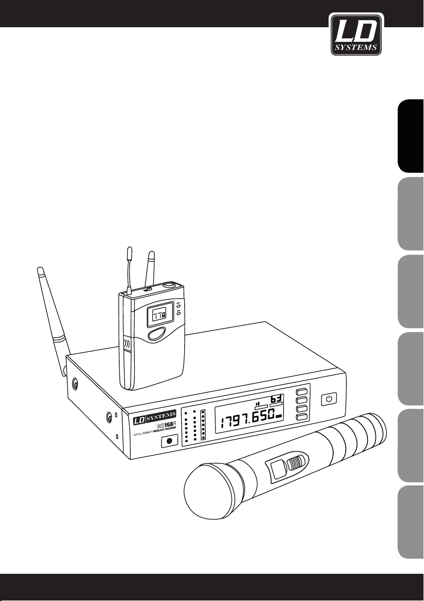
The LD Systems WS1G8 is an advanced 192 channel true diversity UHF wireless system delivering natural
sound with a wide dynamic range, high S/N ratio and low THD in the frequency range from 1785 - 1800 MHz. It
provides consistent audio transmission from 50 Hz to 16 kHz. Handheld and bodypack feature convenient LCD
indication of channel, group and battery status. Automatic channel scanning, infrared frequency sync and the
backlit multifunction receiver display facilitate system setup and operation. The operating time ranges up to 13
hours with high quality AA size batteries.
FRANCAISFRANCAIS FRANCAISFRANCAIS
2
Page 3
LD WS1G8
192 CHANNEL UHF TRUE DIVERSITY WIRELESS SYSTEM
FRANCAISFRANCAIS FRANCAISFRANCAIS
FRANCAISDEUTSCHENGLISH
ITALIANOPOLSKIESPAÑOL
3
Page 4
PREVENTIVE MEASURES:
1. Please read this information carefully.
2. Keep all information and instructions in a safe place.
3. Please follow the instructions.
ENGLISHDEUTSCHFRANCAIS
4. Please observe all warnings. Don‘t remove safety instructions or any other information located on the device.
5. Use the device only in the intended manner.
6. Use only stable and appropriate stands and/or mounts when the device is permanently installed. Make certain
that wall brackets are firmly secured. Make certain that the unit is installed securely and cannot fall down.
7. When installing please observe the corresponding safety standards for your country.
8. Do not install the device near radiators, heat accumulators, ovens or other sources of heat. Make certain that
the device is always installed so that is cooled sufficiently and cannot overheat.
9. Do not place open sources of ignition, e.g., burning candles, on the device.
10. Do not cover ventilation slots.
11. Do not operate the device in the immediate vicinity of water. Do not expose this equipment to combustible
materials, liquids or gases.
12. Please make certain that dripping or splashing water cannot get inside the device. Do not put objects filled
with fluids, such as vases or drinking vessels, on top of the device.
13. Make certain that objects cannot fall into the device.
14. Use the device only with accessories with which the manufacturer intends the device to be used.
15. CAUTION: If this device has a mains connector equipped with protective earth, it must be connected to a
mains socket with a protective ground connection. Never disable the function of the protective ground connection
of the included power cord.
16. Do not turn on the device immediately if it was exposed to strong temperature fluctuations (for example after
transportation). Moisture and condensation may damage the device. Leave the device switched off until it has
reached room temperature.
17. Do not open the device and do not make any changes to the device.
18. Before connecting to mains power, make certain that the mains voltage and the mains frequency are the
ESpAñoLpoLSKIITALIANo
same as the operating values of the device (see type label). If the device is equipped with a supply voltage selector switch, make certain that the values of the device match the values of the mains power before connecting.
If the plug on the included cord does not fit your mains outlet, contact your electrician.
19. Make certain that the power cord is not stepped on. Protect the power cord against pinching, especially at
the device plug and the power plug.
20. In order to prevent damage or accidents, for example, due to tripping hazards, check all connections once
you have connected the device.
FRANCAISFRANCAIS FRANCAISFRANCAIS
21. When connecting the device, make certain that the power plug remains readily accessible.
Always pull out the power plug when the device is not in use or when you clean the device. Disconnect the
power cord by pulling the plug not the cable. Never touch the power cable and power adapter with wet hands.
22. Avoid switching the device on and off at short intervals, because it may shorten the durability of the device.
23. IMPORTANT: Replace fuse only by fuse of same type and rating! If fuse blows repeatedly please contact
authorized service center!
24. In order to disconnect the device completely from the mains voltage, the power plug must be unplugged.
25. If your device is equipped with a Volex power connector, the matching Volex device plug must be unlocked
in order to disconnect it. This also means that a tug on the power cord can pull the device out of place, thus
causing personal injuries and/or property damage. Thus please make certain to route your cables carefully.
4
Page 5
PREVENTIVE MEASURES:
26. If there is a risk of lightning strike or during extended periods of disuse, unplug the power plug.
27. During transport, make certain that the equipment being transported cannot fall down and possibly
cause personal injuries and/or property damage.
28. If your device no longer works properly, if it has been exposed to liquids or an object has fallen inside it or
if it has been damaged in some other manner, turn the device off immediately und unplug the power plug. This
device should be repaired only by authorized experts.
29. Use only a dry cloth to clean the device.
30. Comply with all of the disposal laws that are applicable in your country. During disposal, please separate
plastic and paper/cardboard.
31. Plastic bags must be kept out of the reach of children.
ENGLISH
FRANCAISFRANCAIS FRANCAISFRANCAIS
CAUTION
RISK OF ELECTRIC SHOCK
DO NOT OPEN
CAUTION:
To reduce the risk of electric shock, do not remove cover (or back). No user serviceable parts inside. Refer
servicing to qualified personnel.
The lightning flash with arrowhead symbol within an equilateral triangle is intended to alert the
user to the presence of uninsulated “dangerous voltage” within the product´s enclosure that may be
of sufficient magnitude to constitute a risk to persons.
The exclamation mark within an equilateral triangle is intended to alert the user to the presence of
important operating and maintenance (servicing) instructions in the literature accompanying the
appliance.
CAUTION! HIGH VOLUME!
This product is designed for professional use. Therefore the commercial use of this equipment is liable to the
rules and regulations of the Accident Prevention & Insurance Association of your industry sector. Adam Hall as a
manufacturer is bound to inform you formally about the existence of eventual sanitary risks.
Risk of hearing damage due to prolonged exposure to excessive volumes: When using this product high sound
pressure levels (SPL) can be generated, sufficient to cause permanent hearing damage to performers, production
crew and audience members. Caution should be taken to avoid prolonged exposure SPL in excess of 90 dB.
FRANCAISDEUTSCHENGLISH
ITALIANOPOLSKIESPAÑOL
5
Page 6
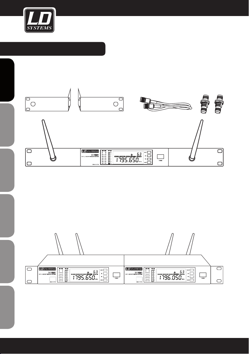
SYSTEM COMPONENTS & INSTALLATION:
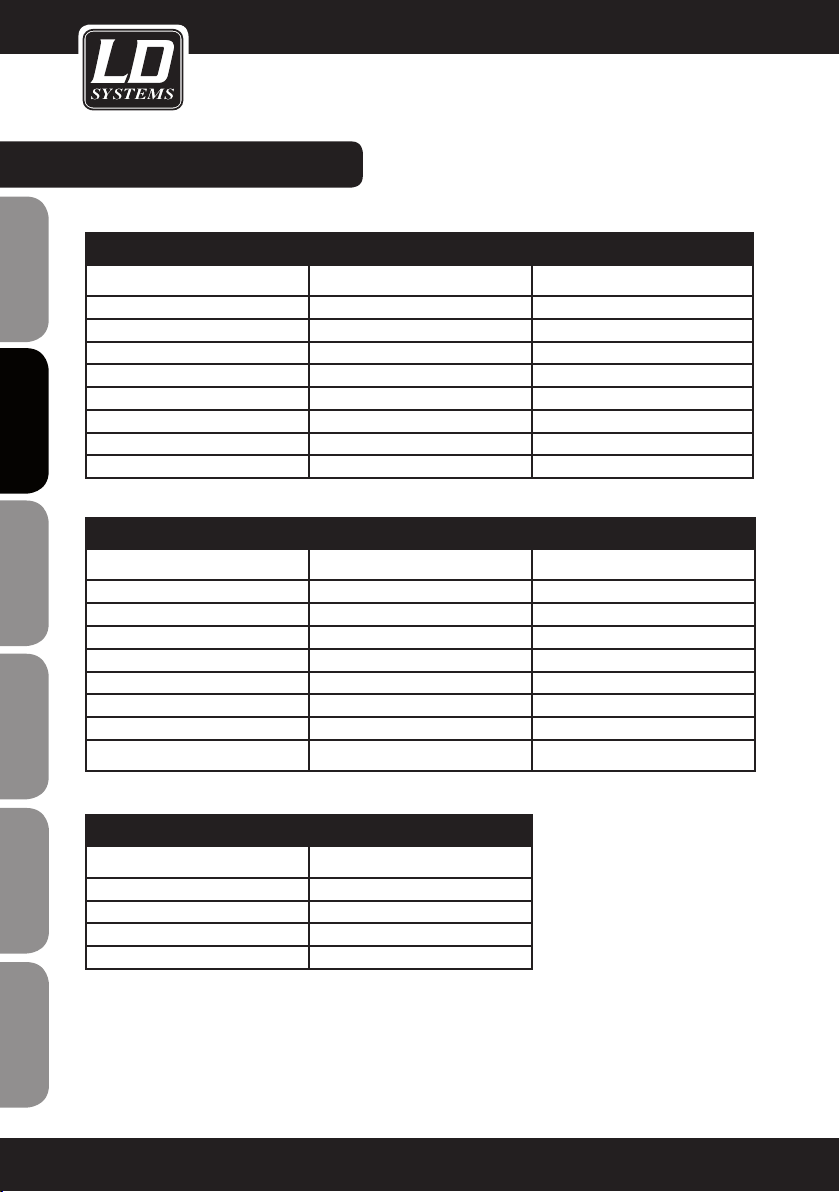
ALL SINGLE RECEIVER SYSTEMS INCLUDE
1 x WS1G8 single receiver
1 x WS1G8 transmitter (handheld or bodypack with microphone / guitar cable)
2 x antenna
ENGLISHDEUTSCHFRANCAIS
1 x power adapter
2 x AA size battery
1 x audio cable
1 x user‘s manual
1 x carrying case
ALL DOUBLE RECEIVER SYSTEMS INCLUDE
1 x WS1G8 double receiver
2 x WS1G8 transmitter (handheld or bodypack with microphone / guitar cable)
2 x antenna
1 x power adapter
4 x AA size battery
1 x audio cable
1 x rack kit (2 x rack mount brackets, 2 x TNC cable, 2 x TNC adapter, 2 x dummy plates, 1 set of screws)
1 x user‘s manual
1 x carrying case
INSTALLATION
For best possible reception place the receiver at a minimum height of 1 m and align the antennas upwards in
V-shape. Attend that transmitters and receivers are in direct line-of-sight and make sure that there is a minimum
distance of 50 cm between receiving antennas and metal objects. Do not position receivers near digitally controlled devices.
ESpAñoLpoLSKIITALIANo
FRANCAISFRANCAIS FRANCAISFRANCAIS
6
Page 7
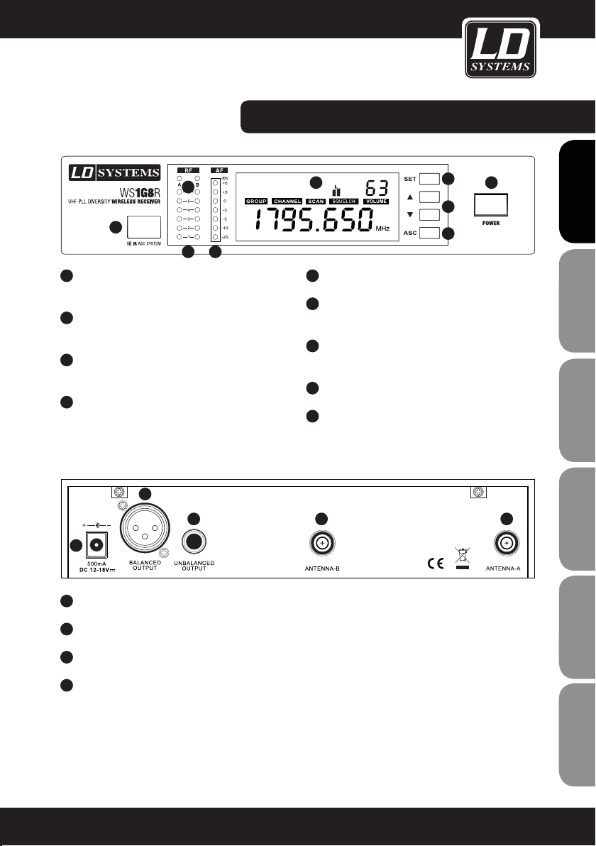
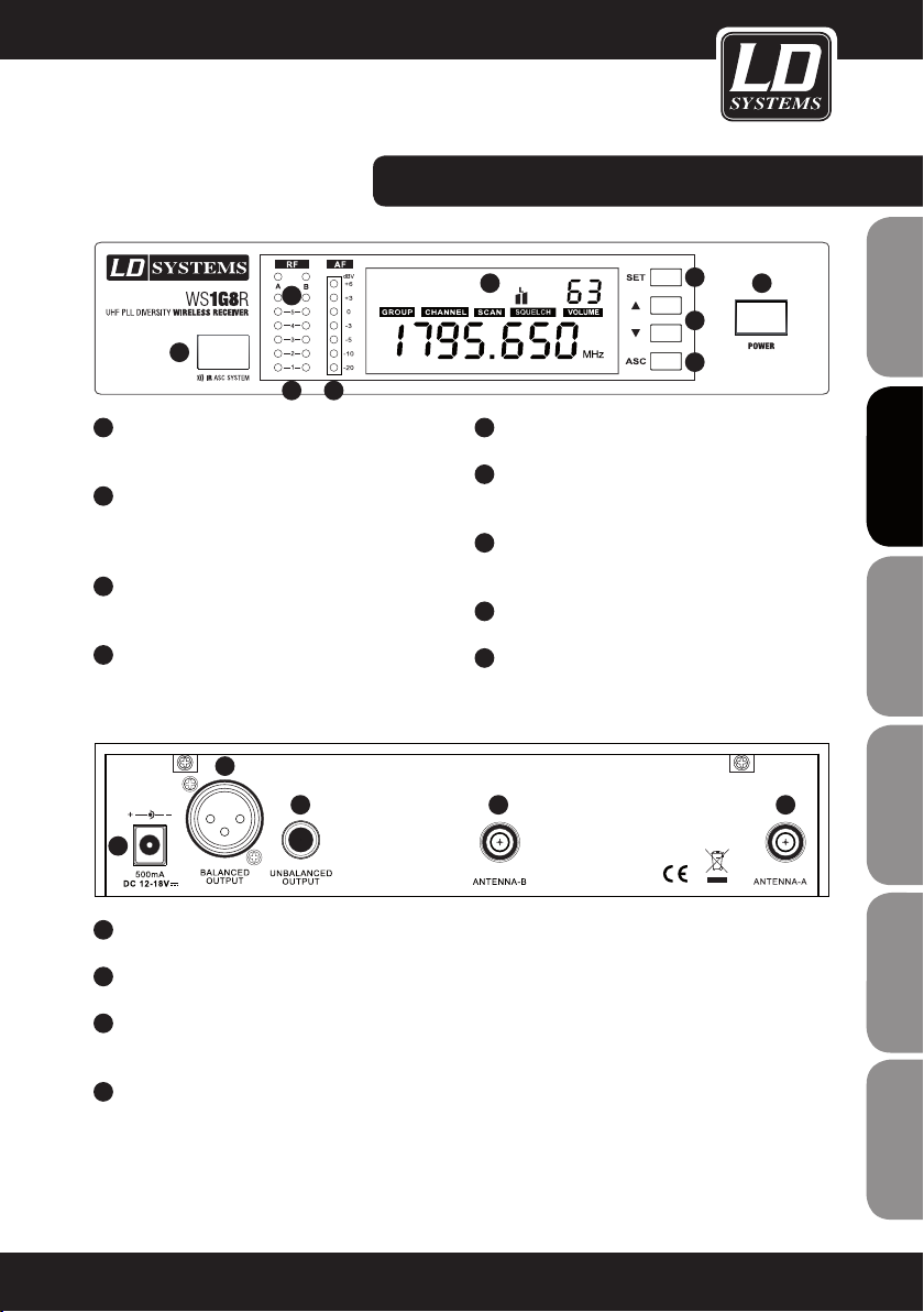
WS1G8R fRONT- / BACk PANEL:
6
5
87
1
POwER ON / Off
Push and hold for 1 second
2
SET BUTTON
Push and hold for 1 second to access menu items
3
VOLUME / VALUE
Up and Down buttons
4
ASC BUTTON
Frequency sync via infrared
2
3 1 1
4
9
5
INfRARED INTERfACE
6
ANTENNA A / B LEDS
Indicates whether antenna input A or B is active
7
6 SEGMENT Rf (RADIO fREqUENCY) SIGNAL
LEVEL METER ANTENNA INPUT A / B.
8
7 SEGMENT AUDIO LEVEL METER
9
ILLUMINATED MULTIfUNCTIONAL DISPLAY
2
3
4
1
FRANCAISFRANCAIS FRANCAISFRANCAIS
FRANCAISDEUTSCHENGLISH
1
TNC SOCkETS ANTENNA A / B.
2
BALANCED XLR OUTPUT.
3
UNBALANCED 6.3 MM jACk OUTPUT.
4
DC SOCkET. ONLY USE THE SUPPLIED POwER
ADAPTER.
ITALIANOPOLSKIESPAÑOL
7
Page 8
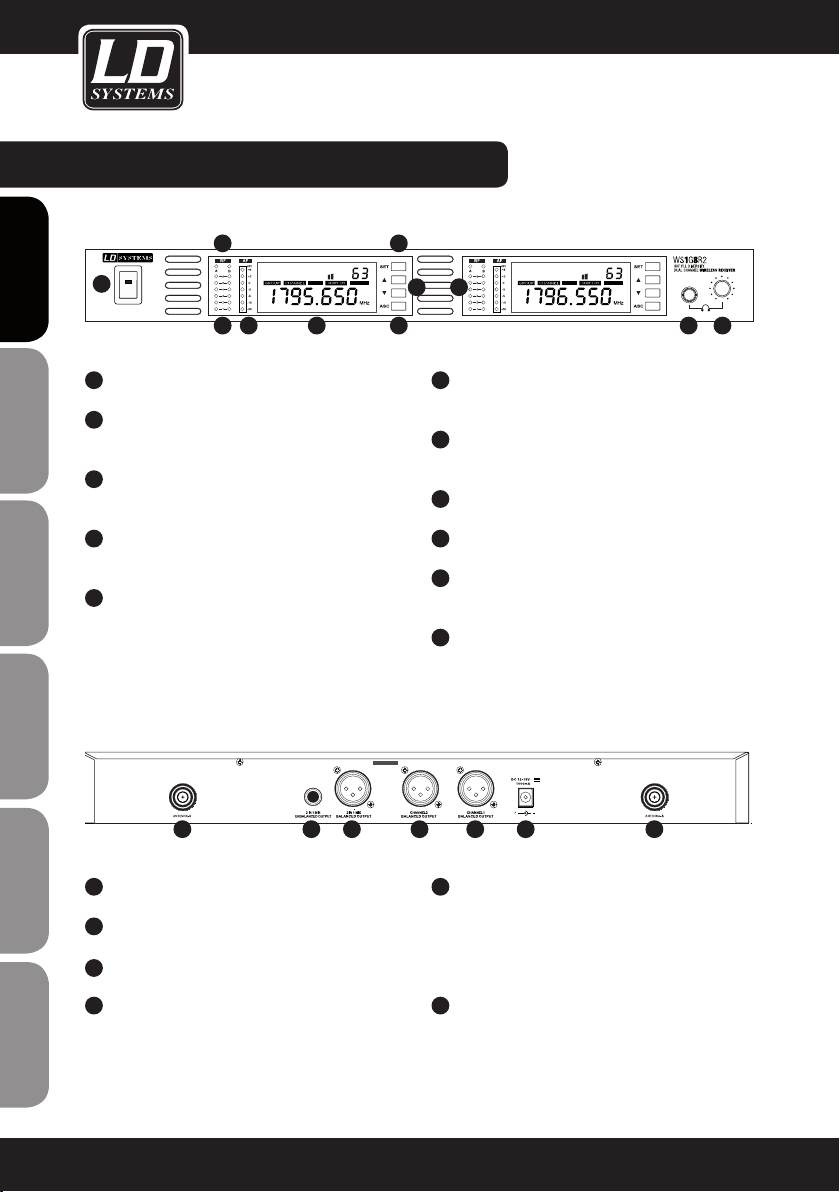
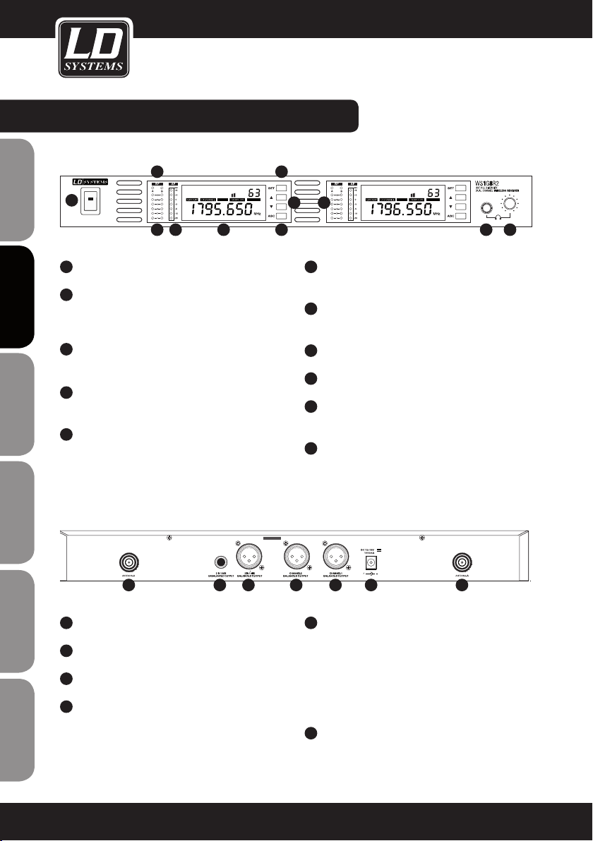
WS1G8R2 fRONT- / BACk PANEL:
VOLUMEAUTO
L
VOLUME
L
AUTO
ENGLISHDEUTSCHFRANCAIS
1
1
2
3
4
5
ESpAñoLpoLSKIITALIANo
6
L
VOLUMEAUTO
7 8 9
POwER ON / Off.
SET BUTTON
Push and hold for 1 second to access menu items
VOLUME / VALUE
Up and Down buttons
ASC BUTTON
Frequency sync via infrared
INfRARED INTERfACE
2
L
VOLUME
3 5
4
6
ANTENNA A / B LEDS
AUTO
Indicates whether antenna input A or B is active
7
6 SEGMENT Rf (RADIO fREqUENCY) SIGNAL
LEVEL METER ANTENNA INPUT A / B
8
7 SEGMENT AUDIO LEVEL METER
9
ILLUMINATED MULTIfUNCTIONAL DISPLAY
10
HEADPHONES OUTPUT
6.3 mm stereo jack.
11
HEADPHONES VOLUME.
10 11
1
FRANCAISFRANCAIS FRANCAISFRANCAIS
2
3
4
8
1 5 4 3 2 6 1
TNC SOCkETS ANTENNA A / B
BALANCED XLR OUTPUT CHANNEL 1
BALANCED XLR OUTPUT CHANNEL 2
BALANCED XLR MIX OUTPUT
This output provides a mix of both receivers
audio signals. For individual volume control adjust
the volume on the front panel of each receiver
separately.
5
UNBALANCED MIX 6.3 MM jACk OUTPUT
This output provides a mix of both receivers
audio signals. For individual volume control adjust
the volume on the front panel of each receiver
separately.
6
DC SOCkET. ONLY USE THE SUPPLIED POwER
ADAPTER
Page 9
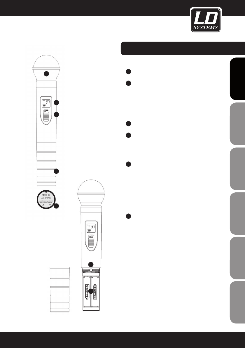
HANDHELD MICROPHONE:
1
1
2
3
5
6
4
MICROPHONE HEAD
2
BACkLIT LCD
Displays group, channel and a 4 segment battery
status indicator. If the battery symbol blinks, the
batteries need to be replaced immediately.
NOTE: Backlight will turn off automatically after a
brief moment.
3
ON / Off SwITCH
4
GAIN CONTROL
Handle carefully! Use only suitable screwdriver!
Turn left to decrease gain, turn right to increase
gain.
5
BATTERY COMPARTMENT
To replace batteries, unscrew cover counterclockwise, remove batteries, insert 2 new AA size
batterries (direction as shown in the compartment) and screw the cover onto the handheld
microphone clockwise. Make shure that the
cover is screwed tightly in order to maintain safe
operation.
6
IR INfRARED INTERfACE
Located on the bottom side of the handheld
microphone.
For frequency synchronisation push the ASC button on the receiver (the ASC symbol in the display
blinks) and hold the (switched on) transmitter with
its infrared interface facing direct to the infrared
interface of the receiver in a distance between 5
and 20 cm.
FRANCAISFRANCAIS FRANCAISFRANCAIS
FRANCAISDEUTSCHENGLISH
5
ITALIANOPOLSKIESPAÑOL
9
Page 10

BODYPACk TRANSMITTER:
1
ON / Off AND MUTE SwITCH
Push and hold for 2 seconds to switch transmitter
ENGLISHDEUTSCHFRANCAIS
ESpAñoLpoLSKIITALIANo
on or off.
Press briefly to activate mute function. Press
again briefly to deactivate mute function.
2
BACkLIT LCD
Displays group, channel and a 3 segment battery
status indicator. If the battery symbol and the
green ASC LED blink, the batteries need to be
replaced immediately. Note: Backlight will turn off
automatically after a brief moment.
3
ANTENNA
4
ASC LED
Green LED lights up continuously if power is
switched on.
Green LED blinks during frequency synchronisation.
Green LED blinks when batteries are low.
5
MUTE LED
Lights up red when mute function is activated.
6
BATTERY COMPARTMENT
To replace batteries slightly press on marked positions on left and right side of the cover and open
forward. Remove batteries, insert 2 new AA size
batteries (direction as shown in the compartment)
and close the cover.
3
2
1
7
4
5
8
6
FRANCAISFRANCAIS FRANCAISFRANCAIS
10
7
IR INfRARED INTERfACE
For frequency synchronisation open cover and
push the ASC button on the receiver (the ASC
symbol in the display blinks) and hold the (switched on) transmitter with its infrared interface facing direct to the infrared interface of the receiver
in a distance between 5 and 20 cm.
8
SELECT
Manual setting of group and channel.
Open cover, press and hold button until only group
number appears. Release button. Group number
blinks. Now press button briefly to change value
step by step until desired group appears. Carry out
the same procedure to change channel number.
The display will return to standard after a short
period of time of non-activity automatically.
Page 11

9
INPUT
3-pin mini XLR input for the supplied microphone
or guitar cable.
BODYPACk TRANSMITTER:
10
GAIN SwITCH
Select the appropriate gain setting.
MIC = microphone
0dB = guitar with passive pickup
-10dB = guitar with active pickup
If the audio signal overloads the receiver, switch
the gain to the next lower setting.
11
BELT CLIP
Attach the bodypack to a belt or guitar strap as
shown below.
BODYPACk MINI-XLR PIN ASSIGNMENT
MINI-XLR
2
3
1
6,3 mm jack
sleeve tip
9
10
FRANCAISFRANCAIS FRANCAISFRANCAIS
FRANCAISDEUTSCHENGLISH
11
MINI-XLR
2
1
3
Headset, lavalier or wind instrument microphoneGuitar & Bass and other high impendance sources
MINI-XLR
R
2,2k
2
1
3
Headset, lavalier or wind instrument microphone with low sensitivity. 2,2 kOhm
resistor soldered on pin 2 and pin 3 increases gain.
ITALIANOPOLSKIESPAÑOL
11
Page 12
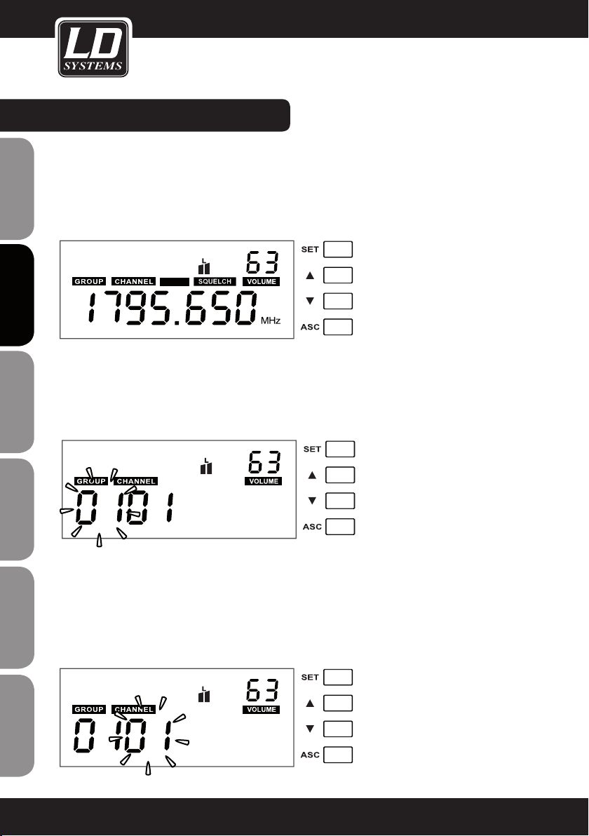
SYSTEM SETTINGS:
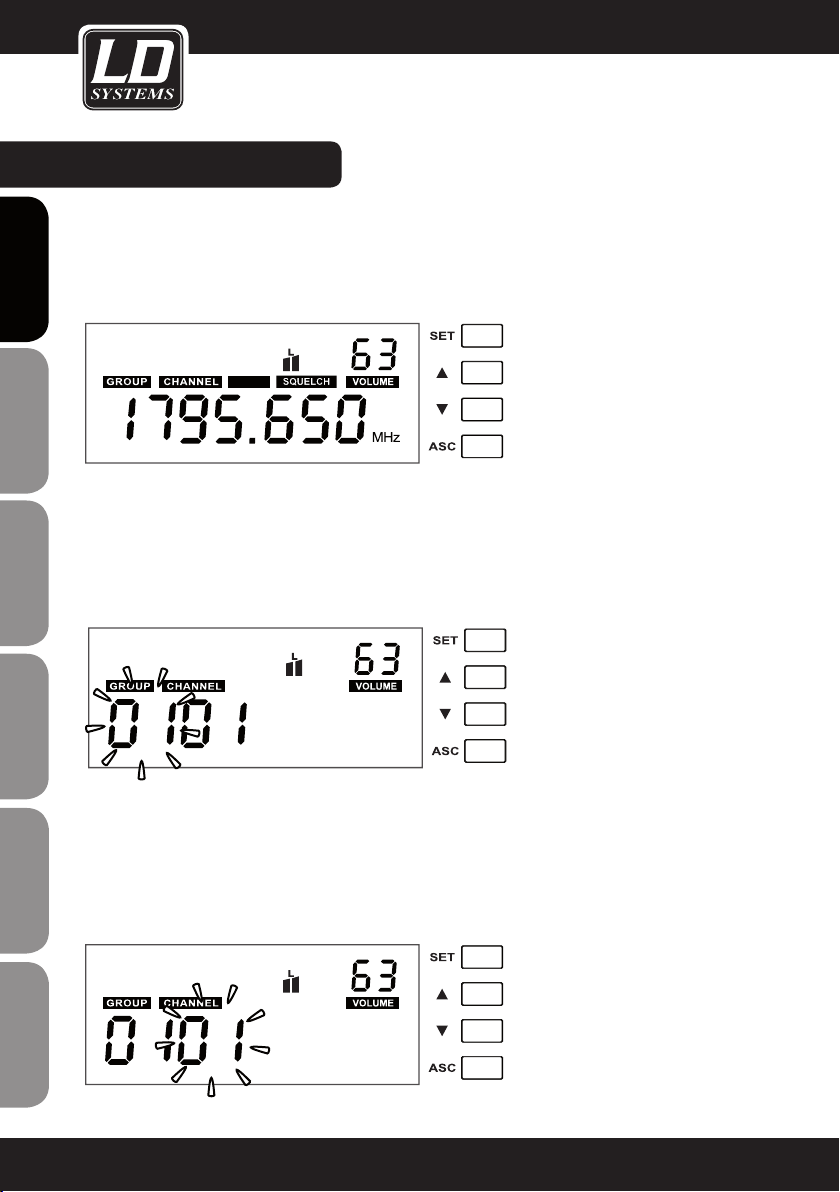
STANDARD DISPLAY
The standard display shows the preselected frequency, squelch setting and volume.
VOLUME
Use the Up and Down buttons to set the desired volume (00 - 63).
ENGLISHDEUTSCHFRANCAIS
AUTO
GROUP
Push the SET button and hold it for 1 second. GROUP and first two digits blink. Push the Up and Down buttons to
set the desired group (01 - 16). Press SET again to confirm.
The display will return to standard after a short period of time of non-activity automatically.
NOTE: Each of the groups 01 - 16 consists of 12 channels, each corresponding to a specific frequency.
ESpAñoLpoLSKIITALIANo
CHANNEL
Push the SET button, hold it for 1 second and press SET again. CHANNEL and 2 digits below blink. Push the Up
and Down buttons to set the desired channel (01 - 12). Press SET again to confirm.
The display will return to standard after a short period of time of non-activity automatically.
Once a specific frequency (group and channel) has been selected, the transmitter (handheld or bodypack) has to
FRANCAISFRANCAIS FRANCAISFRANCAIS
be synchronized to the same frequency (group and channel) via the ASC function.
12
Page 13
SYSTEM SETTINGS:
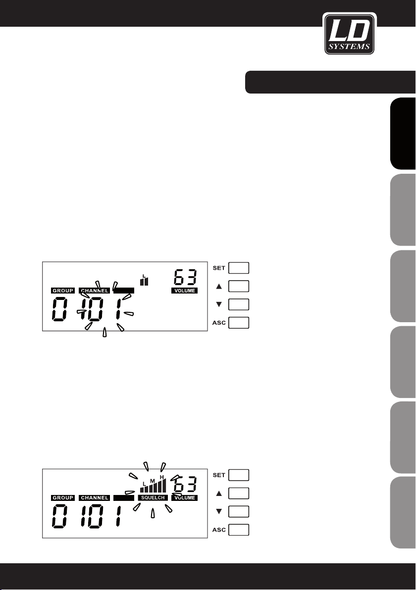
CHANNEL SCAN fUNCTION
Push the SET button, hold it for 1 second and press SET again twice. CHANNEL, AUTO and 2 digits below blink.
Push the Up or Down button to start the channel scan process. After scanning is complete, the display shows the
automatically selected interference free channel.
When using multi-systems and frequency selection is done by the channel scan function, already set up systems
should remain switched on for further channel scan processes. The frequency scan function relates to the
frequency presets in the pre-selected group (01 - 16).
The accuracy of the scan result depends on the environment and the number of simultaneously used wireless
systems. If the scan function does not recognize an already used frequency under adverse conditions, start the
scan process again until an open frequency has been located.
Note: Each frequency channel must come from the same group (01 - 16) when using multi-systems.
Important: Do not operate more than one wireless system on the same frequency at the same time and location.
This causes unwanted loud noise due to radio interference.
AUTO
SqUELCH
The squelch function eliminates unpleasant noise when the transmitter is switched off. It also suppresses sudden noise when there is no longer sufficient transmission power received by the receiver.
Adjust the squelch (with transmitter switched off) to the lowest possible setting that suppresses unwanted noise.
Recommended setting for standard applications is „L“. Setting “H” can cause smaller distance of transmission
path under unfavourable conditions.
Push the SET button, hold it for 1 second and press SET again 3 times. SQUELCH and the symbols above blink.
Push the Up and Down buttons to adjust the desired setting (L = Low, M = Mid, H = High). Press SET again to
confirm.
The display will return to standard after a short period of time of non-activity automatically.
CAUTION: Set the volume of the connected PA system to a minimum before adjusting the squelch function!
FRANCAISFRANCAIS FRANCAISFRANCAIS
FRANCAISDEUTSCHENGLISH
AUTO
ITALIANOPOLSKIESPAÑOL
13
Page 14

SYSTEM SETTINGS:
ASC (frequency synchronisation via infrared)
The transmission frequency of a wireless system has to be the same in both transmitter and receiver.
Once a specific frequency (group and channel) has been selected, the transmitter (handheld or bodypack) has to
be synchronized to the same frequency (group and channel) via the ASC function.
ENGLISHDEUTSCHFRANCAIS
Push the ASC button
mitter with its infrared interface
5 and 20 cm. After a short moment the synchronisation process is done and the RF signal level meter
receiver indicates a signal.
2
ESpAñoLpoLSKIITALIANo
1
on the receiver (the ASC symbol in the display blinks) and hold the (switched on) trans-
2
facing direct to the infrared interface of the receiver in a distance between
1
2
3
of the
LOw BATT (low batteries)
FRANCAISFRANCAIS FRANCAISFRANCAIS
If the „LOW BATT“ indicator blinks in the receiver display, the batteries in the transmitter must be replaced immediately..
14
3
Page 15

PROBLEM DISPLAY SOLUTION
No sound or volume
too low.
Transmitter: Display is turned
off.
Receiver: Display is turned off. Check power connection.
Receiver: RF indicator is off.
Transmitter: Power is turned
on.
Make certain that transmitter is turned on.
Make sure that batteries are ok.
Turn power on.
Check up that transmitter and receiver are set to
the same frequency.
Reduce distance between transmitter and receiver.
Attend that transmitter and receiver are in direct
line-of-sight.
TROUBLE SHOOTING:
FRANCAISFRANCAIS FRANCAISFRANCAIS
Distortion or unwanted
noise.
Distorted sound.
Receiver: RF indicator is
illuminated.
Bodypack transmitter: Display
is turned on, Mute LED lights
up.
Receiver: RF indicator is
illuminated.
Receiver: RF indicator is
illuminated.
Transmitter: Battery symbol
blinks.
Receiver: AF level meter too
high.
Make certain that antennas of receiver are con
nected and positioned upwards in V-shape.
Deactivate mute function.
Increase volume of receiver.
Increase gain of transmitter.
Check audio connection of receiver and mixing
board.
Check mixing board settings.
Remove possible reasons of interference (digitally
controlled units, other wireless systems in same
location).
Set wireless system to different transmission
frequency.
Replace batteries
Reduce gain of transmitter.
-
FRANCAISDEUTSCHENGLISH
ITALIANOPOLSKIESPAÑOL
15
Page 16
RACk INSTALLATION:
RACkMOUNT kIT LDwS100Rk (OPTIONAL) fOR 1 X LDwS1G8 RECEIVER CONSISTING Of:
2 X RACk BRACkETS, 2 X TNC CABLES, 2 X TNC ADAPTERS, SET Of SCREwS
ENGLISHDEUTSCHFRANCAIS
RACkMOUNT kIT LDwS100Rk2 (OPTIONAL) fOR 2 X LDwS1G8 RECEIVER CONSISTING Of:
1 X 19“ RACk ADAPTER, SET Of SCREwS
ESpAñoLpoLSKIITALIANo
FRANCAISFRANCAIS FRANCAISFRANCAIS
16
Page 17
SPECIfICATIONS:
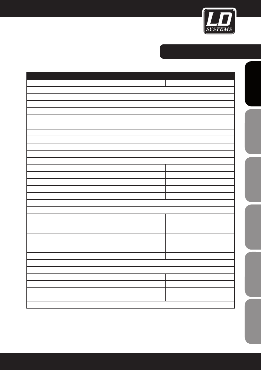
RECEIVER
Model name: LDWS1G8R LDWS1G8R2
Receiver type: true diversity
Modulation: FM
Frequency range: 1785 - 1800 MHz
Channels: 192 (16 x 12)
Groups: 16
Antenna connectors: 2 x TNC
Frequency response: 50 - 16.000 Hz
Squelch: Low, Mid, High
Transmission optimisation: Pilot tone
THD: <0.8%
Signal-to-noise ratio: >90 dB
Balanced output: XLR 2 x XLR
Balanced mix output: XLR
Unbalanced output: 6.3 mm jack
Unbalanced mix output: 6.3 mm jack
Headphones output: 6.3 mm stereo jack
Audio output level (balanced): +6 dBu
Audio output level (unbalanced): 0 dBu
Controls:
Indicators:
Operating voltage: 12 - 18 V DC, 500 mA 12 - 18 V DC, 1000 mA
Operating temperature range: -10°C … 45°C
Relative humidity in operation: 25% … 85%
Dimensions (W x H x D): 212 x 45 x 163 mm 483 x 45 x 163
Weight: 0,92 kg 2,24 kg
Accessories included:
Features: channel scan function, infrared frequency synchronisation
power on/off, set, value up, value
down, ASC
multifunctional LC-display, HF-level
antenna A/B, audio level
power adapter, 2 x antenna, audio
cable
power on/off, 2 x set, 2 x value up,
2 x value down, 2 x ASC, headphones volume
2 x multifunctional LC-display, 2
x HF-level antenna A/B, 2 x audio
level
power adapter, 2 x antenna, audio
cable, rack kit
FRANCAISFRANCAIS FRANCAISFRANCAIS
FRANCAISDEUTSCHENGLISH
ITALIANOPOLSKIESPAÑOL
17
Page 18
SPECIfICATIONS:
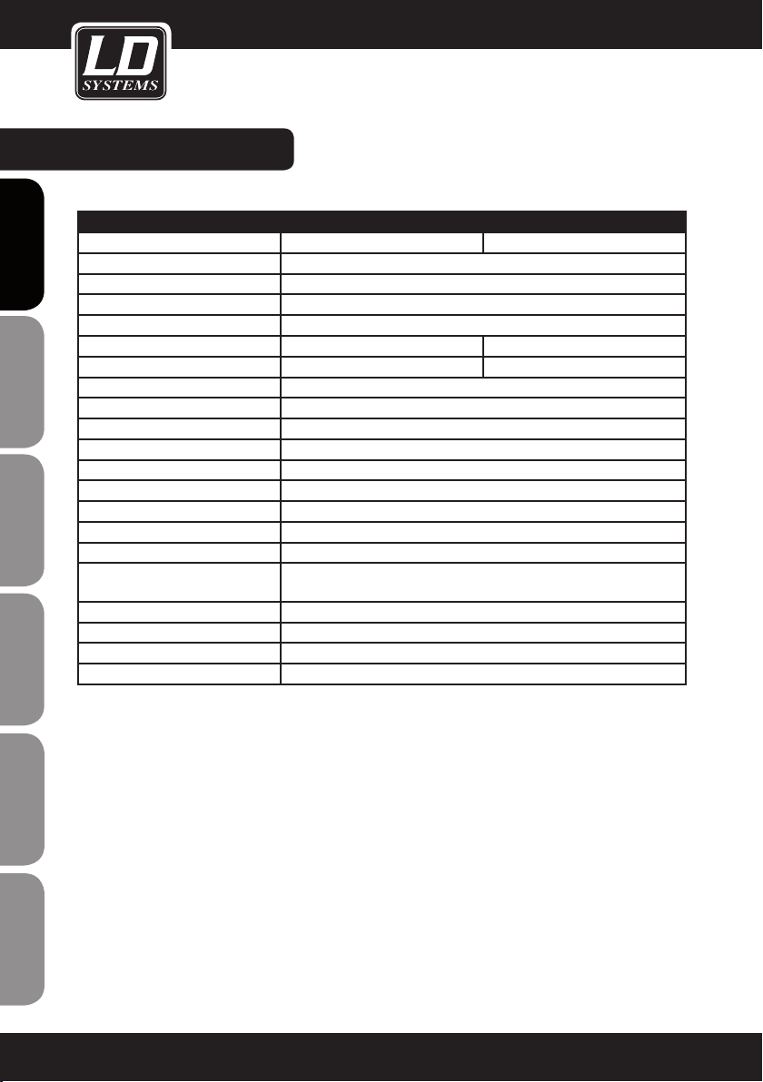
HANDHELD TRANSMITTER
Model name: LDWS1G8MD LDWS1G8MC
ENGLISHDEUTSCHFRANCAIS
ESpAñoLpoLSKIITALIANo
Modulation: FM
Frequency range: 1785 - 1800 MHz
Channels: 192 (16 x 12)
Groups: 16
Microphone type: dynamic condenser
Polar pattern: cardioid cardioid
Frequency response: 50 - 16.000 Hz
THD: <0.8%
Signal-to-noise ratio: >90 dB
RF output power: 10 mW
Controls: Power on/off
Indicators: multifunctional LC-display
Power supply: 2 x AA battery
Operating time: up to 13 h (depending on batteries)
Operating temperature range: -10°C … 45°C
Relative humidity range in ope-
ration:
Dimensions (L x Ø): 245 x 51 mm
Weight: 0,34 kg
Accessories included: 2 x AA battery
Features: infrared frequency synchronisation
25% … 85%
FRANCAISFRANCAIS FRANCAISFRANCAIS
18
Page 19
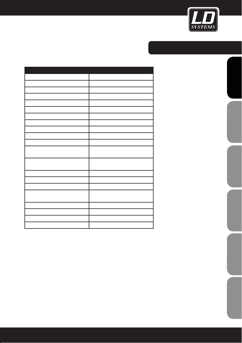
BODYPACk TRANSMITTER
Model name: LDWS1G8BP
Modulation: FM
Frequency range: 1785 - 1800 MHz
Channels: 192
Groups: 16
Input: 3-pin mini-XLR
Frequency response: 50 - 16.000 Hz
THD: <0.8%
Signal-to-noise ratio: >90 dB
RF output power: 10 mW
Controls:
Indicators:
Power supply: 2 x AA batteries
Operating time: up to 13 h (depending on batteries)
Operating temperature range: -10°C … 45°C
Relative humidity range in ope-
ration:
Dimensions (W x H x D): 65 x 90 x 24 mm
Weight (without batteries): 0,09 kg
Accessories included: 2 x AA battery
Features: infrared frequency synchronisation
Power / Mute, select, triple gain
switch
multifunctional LC-display, ASC
LED, Mute LED
25% … 85%
SPECIfICATIONS:
FRANCAISFRANCAIS FRANCAISFRANCAIS
FRANCAISDEUTSCHENGLISH
ITALIANOPOLSKIESPAÑOL
19
Page 20
SPECIfICATIONS:
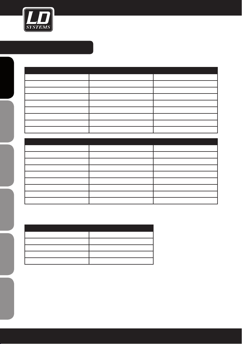
MICROPHONE
ENGLISHDEUTSCHFRANCAIS
Model name: LDWS100MH1 LDWS100MH3
Microphone type: headset headset
Capsule: back-electret condenser back-electret condenser
Polar pattern: cardioid cardioid
Frequency response: 20 - 20.000 Hz 70 - 16.000 Hz
Connector: 3-pin mini-XLR 3-pin mini-XLR
Accessories included: foam windscreen foam windscreen
Features:
LDHSAE1 LDWS100ML LDWS1000MW
headset lavalier microphone wind instrument microphone
back-electret condenser back-electret condenser back-electret condenser
bi-directional cardioid cardioid
80 - 16.000 Hz 20 - 20.000 Hz 50 - 18.000 Hz
3-pin mini-XLR 3-pin mini-XLR 3-pin mini-XLR
foam windscreen foam windscreen foam windscreen
water-repellent
ESpAñoLpoLSKIITALIANo
GUITAR CABLE
Model name: LDWS100GC
Connector 1: 3-pin mini-XLR
FRANCAISFRANCAIS FRANCAISFRANCAIS
Connector 2: 6.3 mm jack
Lenght: 1.5 m
20
Page 21
MANUfACTURER´S DECLARATIONS:
LIMITED wARRANTY
This Limited Warranty applies to the Adam Hall, LD Systems, Defender, Palmer, Cameo and Eminence branded
products.
The statutory warranty rights towards the seller are not affected by this guarantee. In fact, it justifies, additional
independent warranty claims towards Adam Hall.
Adam Hall warrants that the Adam Hall product you have purchased from Adam Hall or from an Adam Hall authorized reseller is free from defects in materials or workmanship under normal use for a period of 2 or 3 years from
the date of purchase.
The Limited Warranty Period starts on the date of purchase. In order to receive warranty services you are required
to provide proof of the purchase date. Your dated sales or delivery receipt, showing the date of purchase, is your
proof of the purchase date. Should products of the brands named above be in need of repair within the limited warranty period, you are entitled to warranty services according to the terms and conditions stated in this document.
This Limited Warranty extends only to the original purchaser of this Adam Hall branded product and is not transferable to anyone who obtains ownership of the Adam Hall branded product from the original purchaser. During
the Limited Warranty Period, Adam Hall will repair or replace the defective component parts or the product. All
component parts or hardware products removed under this Limited Warranty become the property of Adam Hall.
In the unlikely event that your Adam Hall product has a recurring failure, Adam Hall, at its discretion, may elect to
provide you with a replacement unit of Adam Hall´s choice that is at least equivalent to your Adam Hall branded
product in hardware performance.
Adam Hall does not warrant that the operation of this product will be uninterrupted or error-free. Adam Hall is not
responsible for damage that occurs as a result of your failure to follow the instructions included with the Adam
Hall branded product.
This Limited Warranty does not apply,
- to wear parts (e.g. accumulator)
- to any product from which the serial number has been removed or that has been damaged or rendered defective as the result of an accident
- in case of, misuse, abuse, or other external causes
- by operation outside the usage parameters stated in the user´s documentation shipped with the product by use
of spare parts not manufactured or sold by Adam Hall
- by modification or service by anyone other than Adam Hall
These terms and conditions constitute the complete and exclusive warranty agreement between you and Adam
Hall regarding the Adam Hall branded product you have purchased.
FRANCAISFRANCAIS FRANCAISFRANCAIS
FRANCAISDEUTSCHENGLISH
ITALIANOPOLSKIESPAÑOL
21
Page 22

MANUfACTURER´S DECLARATIONS:
LIMITATION OF LIABILITY
If your Adam Hall branded hardware product fails to work as warranted above, your sole and exclusive remedy
shall be repair or replacement. Adam Halls’ maximum liability under this limited warranty is expressly limited
ENGLISHDEUTSCHFRANCAIS
to the lesser of the price you have paid for the product or the cost of repair or replacement of any hardware
components that malfunction in conditions of normal use.
Adam Hall is not liable for any damages caused by the product or the failure of the product, including any lost
profits or savings or special, incidental, or consequential damages. Adam Hall is not liable for any claim made by
a third party or made by you for a third party.
This limitation of liability applies whether damages are sought, or claims are made, under this Limited Warranty
or as a tort claim (including negligence and strict product liability), a contract claim, or any other claim. This limitation of liability cannot be waived or amended by any person. This limitation of liability will be effective even if
you have advised Adam Hall of an authorized representative of Adam Hall of the possibility of any such damages.
This limitation of liability however, will not apply to claims for personal injury.
This Limited Warranty gives you specific legal rights. You may also have other rights that may vary from state to
state or from country to country. You are advised to consult applicable state or country laws for a full determination of your rights.
REQUESTING wARRANTY-SERVICE
To request warranty service for the product, contact Adam Hall or the Adam Hall authorized reseller from which
you purchased the product.
EC DECLARATION OF CONFORMITY
ESpAñoLpoLSKIITALIANo
These devices meet the essential requirements and further relevant specifications of Directives 1999/5/EC (R &
TTE), 2004/108/EC (EMC) and 2006/95/EC (LVD). For more information, see www.adamhall.com.
CORRECT DISPOSAL OF THIS PRODUCT (ELECTRICAL WASTE)
(Applicable in the European Union and other European countries with separate collection systems)
This marking shown on the product or its literature, indicates that it should not be disposed with other household
wastes at the end of its working life. To prevent possible harm to the environment or human health from uncon-
FRANCAISFRANCAIS FRANCAISFRANCAIS
trolled waste disposal, please separate this from other types of wastes and recycle it responsibly to promote the
sustainable reuse of material resources.
Household users should contact either the retailer where they purchased this product, or their local government
office, for details on where and how they can recycle this item in an enviromentally friendly manner.
Business users should contact their supplier and check the terms and conditions of the purchase contract. This
product should not be mixed with other commercial wastes for disposal.
22
Page 23
wEEE-DECLARATION
Your LD-Systems product was developed and manufactured with high quality materials and components wich
can be recycled and/or reused. This symbol indicates that electrical and electronic equipment must be disposed
of separately from normal waste at the end of its operational lifetime.
Please dispose of this product by bringing it to your local collection point or recycling centre for such equipment.
This will help to protect the environment in which we all live.
BATTERIES AND ACCUMULATORS
The supplied batteries or rechargeable batteries can be recycled. Please dispose of them as special waste or
return them to your specialist dealer. In order to protect the environment, only dispose exhausted batteries.
ECOLOGY AND ENERGY SAVING
Saving electric energy helps to protect the environment. Please turn off all electrical equipment when it is not in
use. To avoid power consumption in idle mode, disconnect all electrical equipment from mains when not in use.
FRANCAISFRANCAIS FRANCAISFRANCAIS
FRANCAISDEUTSCHENGLISH
Adam Hall GmbH, all rights reserved. The technical data and the functional product characteristics can be subject
to modifications. The photocopying, the translation, and all other forms of copying of fragments or of the integrality of this user’s manual is prohibited.
ITALIANOPOLSKIESPAÑOL
23
Page 24
ENGLISHDEUTSCHFRANCAIS
Sie haben die richtige Wahl getroffen!
Diese LD Systems Produkte werden Sie lange Jahre durch Zuverlässigkeit, Wirtschaftlichkeit und einfaches
Handling überzeugen. Dafür garantiert LD Systems mit seinem Namen und seiner in vielen Jahren erworbenen
Kompetenz als Hersteller hochwertiger Geräte.
Nehmen Sie sich nun ein paar Minuten Zeit, diese Anleitung zu lesen. Wir möchten, dass Sie einfach
und schnell in den Genuss dieser Technik kommen.
Mehr Informationen zu LD SYSTEMS finden Sie auf unserer Internetseite WWW.LD-SYSTEMS.COM
Einführung
ESpAñoLpoLSKIITALIANo
Das neue LD Systems WS1G8 ist ein professionelles True Diversity Funksystem mit 192 UHF-Kanälen im
Frequenzbereich 1785 - 1800 MHz und bietet einen natürlichen Klang mit großem Dynamikumfang, hohem Rauschabstand und einem niedrigen Klirrfaktor. Das System garantiert eine verlässliche Audioübertragung mit einem
Frequenzbereich von 50 Hz bis 16 kHz. Sowohl die Handgeräte als auch der Taschensender verfügen über eine
praktische LC-Anzeige für den Kanal, die Gruppe und den Batteriestatus. Die automatische Kanalsuche, die IRSendersynchronisierung und das beleuchtete Multifunktions-Display am Empfänger sorgen für einen einfachen
Aufbau und Betrieb. Mit hochwertigen Batterien (AA) werden Betriebszeiten von bis zu 13 Stunden erreicht.
FRANCAISFRANCAIS FRANCAISFRANCAIS
24
Page 25
LD WS1G8
192-KANAL UHF TRUE DIVERSITY FUNKMIKROFON-SYSTEM
FRANCAISFRANCAIS FRANCAISFRANCAIS
FRANCAISDEUTSCHENGLISH
ITALIANOPOLSKIESPAÑOL
25
Page 26

SICHERHEITSHINWEISE:
1. Lesen Sie diese Anleitung bitte sorgfältig durch.
2. Bewahren Sie alle Informationen und Anleitungen an einem sicheren Ort auf.
3. Befolgen Sie die Anweisungen.
ENGLISHDEUTSCHFRANCAIS
4. Beachten Sie alle Warnhinweise. Entfernen Sie keine Sicherheitshinweise oder andere Informationen vom
Gerät.
5. Verwenden Sie das Gerät nur in der vorgesehenen Art und Weise.
6. Verwenden Sie ausschließlich stabile und passende Stative bzw. Befestigungen (bei Festinstallationen). Stellen
Sie sicher, dass Wandhalterungen ordnungsgemäß installiert und gesichert sind. Stellen Sie sicher, dass das
Gerät sicher installiert ist und nicht herunterfallen kann.
7. Beachten Sie bei der Installation die für Ihr Land geltenden Sicherheitsvorschriften.
8. Installieren und betreiben Sie das Gerät nicht in der Nähe von Heizkörpern, Wärmespeichern, Öfen oder
sonstigen Wärmequellen. Sorgen Sie dafür, dass das Gerät immer so installiert ist, dass es ausreichend gekühlt
wird und nicht überhitzen kann.
9. Platzieren Sie keine Zündquellen wie z. B brennende Kerzen auf dem Gerät.
10. Die Lüftungsschlitze dürfen nicht blockiert werden
11. Betreiben Sie das Gerät nicht in unmittelbarer Nähe von Wasser. Bringen Sie das Gerät nicht mit brennbaren
Materialien, Flüssigkeiten oder Gasen in Berührung.
12. Sorgen Sie dafür, dass kein Tropf- oder Spritzwasser in das Gerät eindringt. Stellen Sie keine mit Flüssigkeit
gefüllten Behältnisse wie Vasen oder Trinkgefäße auf das Gerät.
13. Sorgen Sie dafür, dass keine Gegenstände in das Gerät fallen können.
14. Betreiben Sie das Gerät nur mit dem vom Hersteller empfohlenen und vorgesehenen Zubehör.
15. ACHTUNG: Wenn das Stromkabel des Geräts mit einem Schutzkontakt ausgestattet ist, muss es an einer
Steckdose mit Schutzleiter angeschlossen werden. Deaktivieren Sie niemals den Schutzleiter des mitgelieferten
Kaltgerätekabels.
16. Schalten Sie das Gerät nicht sofort ein, wenn es starken Temperaturschwankungen ausgesetzt war (beispielsweise nach dem Transport). Feuchtigkeit und Kondensat könnten das Gerät beschädigen. Schalten Sie das
ESpAñoLpoLSKIITALIANo
Gerät erst ein, wenn es Zimmertemperatur erreicht hat.
17. Öffnen Sie das Gerät nicht und verändern Sie es nicht.
18. Bevor Sie das Gerät an die Steckdose anschließen, prüfen Sie zuerst, ob die Spannung und die Frequenz
des Stromnetzes mit den auf dem Gerät angegebenen Werten übereinstimmen. Verfügt das Gerät über einen
Spannungswahlschalter, schließen Sie das Gerät nur an die Steckdose an, wenn die Gerätewerte mit den Werten
des Stromnetzes übereinstimmen.
Wenn das mitgelieferte Netzkabel nicht in Ihre Netzsteckdose passt, wenden Sie sich an Ihren Elektriker.
FRANCAISFRANCAIS FRANCAISFRANCAIS
19. Treten Sie nicht auf das Kaltgerätekabel. Sorgen Sie dafür, dass das Kaltgerätekabel speziell an der Netz- und
der Gerätebuchse nicht geknickt wird.
20. Überprüfen Sie nach dem Anschluss des Geräts alle Kabelwege, um Schäden oder Unfälle, z. B. durch
Stolperfallen zu vermeiden.
21. Achten Sie bei der Verkabelung des Geräts immer darauf, dass das Netzkabel stets frei zugänglich ist.
Ziehen Sie immer den Netzstecker, wenn das Gerät nicht benutzt wird, oder Sie das Gerät reinigen möchten.
Ziehen Sie das Kaltgerätekabel immer am Stecker und nicht am Kabel aus der Steckdose.
22. Schalten Sie das Gerät möglichst nicht schnell hintereinander ein und aus, da sonst die Lebensdauer des
Geräts beeinträchtigt werden könnte.
23. WICHTIGER HINWEIS: Ersetzen Sie die Sicherung ausschließlich durch eine Sicherung des gleichen Typs
26
Page 27
SICHERHEITSHINWEISE:
und mit gleichen Werten. Sollte die Sicherung wiederholt auslösen, wenden Sie sich bitte an ein autorisiertes
Servicezentrum.
24. Um das Gerät vollständig vom Stromnetz zu trennen, entfernen Sie das Netzkabel.
25. Wenn Ihr Gerät mit einem Volex-Netzanschluss bestückt ist, muss der passende Volex-Gerätestecker
entsperrt werden, bevor er entfernt werden kann. Das bedeutet aber auch, dass das Gerät durch eine Ziehen
am Kaltgerätekabel verrutschen kann, wodurch Personen verletzt werden und/oder andere Schäden auftreten
können. Verlegen Sie Ihre Kabel daher immer sorgfältig.
26. Entfernen Sie das Netzkabel bei Gefahr eines Blitzschlags oder wenn Sie das Gerät länger nicht verwenden.
27. Achten Sie beim Transport darauf, dass das Gerät nicht herunterfallen und dabei möglicherweise Sach- und
Personenschäden verursachen kann.
28. Wenn Ihr Gerät nicht mehr ordnungsgemäß funktioniert, Flüssigkeiten oder Gegenstände in das Geräteinnere gelangt sind oder das Gerät anderweitig beschädigt wurde, schalten Sie es sofort aus und ziehen Sie den
Stecker. Dieses Gerät darf nur von autorisiertem Fachpersonal repariert werden.
29. Verwenden Sie zur Reinigung des Geräts ein trockenes Tuch.
30. Beachten Sie alle in Ihrem Land geltenden Entsorgungsgesetze. Trennen Sie bei der Entsorgung bitte Kunststoff und Papier bzw. Kartonagen voneinander.
31. Kunststoffbeutel müssen außer Reichweite von Kindern aufbewahrt werden.
CAUTION
RISK OF ELECTRIC SHOCK
ACHTUNG:
Entfernen Sie niemals die Abdeckung, da sonst das Risiko eines elektrischen Schlages besteht. Im Inneren des
Geräts befinden sich keine Teile, die vom Bediener repariert oder gewartet werden können. Lassen Sie Reparaturen ausschließlich von qualifiziertem Service-Personal durchführen.
DO NOT OPEN
ENGLISH
FRANCAISFRANCAIS FRANCAISFRANCAIS
FRANCAISDEUTSCHENGLISH
Das gleichschenkelige Dreieck mit dem Blitzsymbol kennzeichnet
nicht-isolierte, „gefährliche“ Spannungen im Gerät,
die einen für die Gesundheit gefährlichen Stromschlag verursachen können.
Das gleichschenkelige Dreieck mit dem Ausrufezeichen kennzeichnet wichtige Bedienungs- und
Wartungshinweise.
ACHTUNG! HOHE LAUTSTÄRkEN!
Dieses Gerät ist für den professionellen Einsatz vorgesehen. Der kommerzielle Betrieb dieses Geräts unterliegt
den jeweils gültigen nationalen Vorschriften und Richtlinien zur Unfallverhütung. Als Hersteller ist Adam Hall
gesetzlich verpflichtet, Sie ausdrücklich auf mögliche Gesundheitsrisiken hinzuweisen.
Gehörschäden und Dauerbelastung durch hohe Lautstärken: Dieser Lautsprecher kann hohe Schalldruckpegel
(SPL) erzeugen, die bei Künstlern, Mitarbeitern und Zuschauern zu irreparablen Gehörschäden führen können.
Vermeiden Sie länger anhaltende Belastung durch hohe Lautstärken über 90 dB.
ITALIANOPOLSKIESPAÑOL
27
Page 28

SYSTEMkOMPONENTEN & INSTALLATION:
ALLE SYSTEME MIT EINZELEMPfÄNGER BESTEHEN AUS:
1 x WS1G8 Einzelempfänger
1 x LWS1G8 Sender (Handmikrofon oder Taschensender mit Mikrofon-/Gitarrenkabel)
2 x Antennen
ENGLISHDEUTSCHFRANCAIS
1 x Netzadapter
2 x AA-Batterien
1 x Audiokabel
1 x Bedienungsanleitung
1 x Transportbox
ALLE ZwEIfACHEMPfÄNGER-SYSTEME BESTEHEN AUS:
1 x WS1G8 Zweifachempfänger
2 x WS1G8 Sender (Handmikrofon oder Taschensender mit Mikrofon-/Gitarrenkabel)
2 x Antennen
1 x Netzadapter
4 x AA-Batterien
1 x Audiokabel
1 x Rackmount Kit (2 x Rack-Winkel, 2 x TNC-Kabel, 2 x TNC-Adapter, 2 x Blendenbleche, 1 Satz Schrauben)
1 x Bedienungsanleitung
1 x Transportbox
INSTALLATION
Um einen optimalen Empfang zu gewährleisten, sollten Sie den Empfänger in mindesten 1 m Höhe aufstellen und
die Antennen nach oben und in V-Form ausrichten. Achten Sie darauf, dass Sender und Empfänger eine direkte
Sichtverbindung haben und dass zwischen den Empfangsantennen und etwaigen Metallobjekten ein Abstand von
mindestens 50 cm eingehalten wird. Stellen Sie Empfänger nicht in der Nähe von Digitalgeräten auf.v
ESpAñoLpoLSKIITALIANo
FRANCAISFRANCAIS FRANCAISFRANCAIS
28
Page 29
WS1G8R VORDER- / RüCkSEITE:
6
5
87
1
EIN/AUS-SCHALTER
Eine Sekunde lang gedrückt halten
2
SET-TASTE
Eine Sekunde lang gedrückt halten, um MenüParameter aufzurufen
3
LAUTSTÄRkE / wERT
Pfeiltasten (oben/unten)
4
ASC-TASTE
Frequenzsynchronisation über Infrarot
2
3 1 1
4
9
5
INfRAROT-SCHNITTSTELLE
6
ANTENNEN-LEDS A / B
Zeigen an, ob Antenneneingang A bzw. B aktiv ist
7
6-STUfIGE PEGELANZEIGE füR Rf(fUNk)SIGNAL füR ANTENNENEINGÄNGE A / B
8
7-STUfIGE PEGELANZEIGE füR AUDIOSIGNAL
9
BELEUCHTETES MULTIfUNkTIONSDISPLAY
2
3
4
1
FRANCAISFRANCAIS FRANCAISFRANCAIS
FRANCAISDEUTSCHENGLISH
1
TNC-ANTENNENANSCHLüSSE A / B
2
XLR-AUSGANG (SYMMETRISCH)
3
6,3-MM-kLINkENAUSGANG (UNSYMMETRISCH)
4
NETZTEILBUCHSE VERwENDEN SIE AUSSCHLIESSLICH DEN MITGELIEfERTEN
NETZADAPTER.
ITALIANOPOLSKIESPAÑOL
29
Page 30
WS1G8R2 VORDER- / RüCkSEITE:
VOLUMEAUTO
L
VOLUME
L
AUTO
ENGLISHDEUTSCHFRANCAIS
1
1
2
3
4
5
ESpAñoLpoLSKIITALIANo
6
L
VOLUMEAUTO
7 8 9
EIN/AUS-SCHALTER
SET-TASTE
Eine Sekunde lang gedrückt halten, um MenüParameter aufzurufen
LAUTSTÄRkE / wERT
Pfeiltasten (oben/unten)
ASC-TASTE
Frequenzsynchronisation über Infrarot
INfRAROT-SCHNITTSTELLE
2
L
VOLUME
3 5
4
6
ANTENNEN-LEDS A / B
AUTO
Zeigen an, ob Antenneneingang A bzw. B aktiv ist
7
6-STUfIGE PEGELANZEIGE füR Rf(fUNk)SIGNAL füR ANTENNENEINGÄNGE A / B
8
7-STUfIGE PEGELANZEIGE füR AUDIOSIGNAL
9
BELEUCHTETES MULTIfUNkTIONSDISPLAY
10
kOPfHöRERAUSGANG
6,3 mm Stereoklinkenstecker
11
kOPfHöRERLAUTSTÄRkE
10 11
FRANCAISFRANCAIS FRANCAISFRANCAIS
30
1 5 4 3 2 6 1
1
TNC-ANTENNENANSCHLüSSE A / B
2
SYMMETRISCHER XLR-AUSGANG kANAL 1
3
SYMMETRISCHER XLR-AUSGANG kANAL 2
4
SYMMETRISCHER XLR-AUSGANG MIX
An diesem Ausgang liegt eine Mischung der Ausgangssignale der beiden Empfänger an. Um die Kanäle
einzeln auszusteuern, stellen Sie die Pegel der beiden
Empfänger auf der Gerätevorderseite separat ein.
5
UNSYMMETRISCHER 6,3-MM-kLINkENAUSGANG MIX
An diesem Ausgang liegt eine Mischung der Ausgangssignale der beiden Empfänger an. Um die
Kanäle einzeln auszusteuern, stellen Sie die Pegel
der beiden Empfänger auf der Gerätevorderseite
separat ein.
6
NETZTEILBUCHSE VERwENDEN SIE AUSSCHLIESSLICH DAS MITGELIEfERTE STECkERNETZTEIL.
Page 31

HANDMIKROFON:
1
1
2
3
5
6
MIkROfONkAPSEL
2
BELEUCHTETES LC-DISPLAY
Im Display wird die Gruppe, der Kanal sowie der
Batteriestatus (in 4 Stufen) angezeigt. Wenn das
Batteriesymbol blinkt, müssen die Batterien sofort
gewechselt werden.
HINwEIS: Die Hintergrundbeleuchtung wird nach
einem kurzen Moment automatisch ausgeschaltet.
3
EIN/AUS-SCHALTER
4
GAIN-REGLER
Bitte sehr vorsichtig bedienen! Verwenden Sie nur
einen passenden Schraubendreher!
Drehen Sie den Regler nach links, um den Pegel
zu reduzieren, und nach rechts, um den Pegel
anzuheben.
5
BATTERIEEINSCHUBfACH
Um die Batterien zu wechseln, schrauben Sie die
Abdeckung gegen den Uhrzeigersinn auf, setzen
Sie zwei neue AA-Batterien (Ausrichtung siehe
Abbildung im Batteriefach) ein und schrauben Sie
die Abdeckung wieder im Uhrzeigersinn auf das
Handmikrofon. Für einen sicheren Betrieb muss
die Abdeckung wieder fest verschraubt werden.
FRANCAISFRANCAIS FRANCAISFRANCAIS
FRANCAISDEUTSCHENGLISH
6
INfRAROT-MODUL
Die Infrarot-Schnittstelle befindet sich an der
Unterseite des Handmikrofons.
Um die Frequenz zu synchronisieren, drücken Sie
am Empfänger die ASC-Taste (das ASC-Symbol
4
5
im Display blinkt) und richten Sie die InfrarotSchnittstelle des (eingeschalteten) Senders im
Abstand von 5 bis 20 cm direkt auf die InfrarotSchnittstelle des Empfängers.
ITALIANOPOLSKIESPAÑOL
31
Page 32

TASCHENSENDER:
1
ENGLISHDEUTSCHFRANCAIS
2
3
4
5
ESpAñoLpoLSKIITALIANo
6
FRANCAISFRANCAIS FRANCAISFRANCAIS
7
EIN/AUS UND MUTE
Halten Sie die Taste zwei Sekunden lang gedrückt,
um den Sender ein- oder auszuschalten.
Drücken Sie die Taste kurz, um die Stummschaltung zu aktivieren. Drücken Sie die Taste
erneut kurz, um die Stummschaltung wieder zu
deaktivieren.
BELEUCHTETES LC-DISPLAY
Im Display wird die Gruppe, der Kanal sowie der
Batteriestatus (in 3 Stufen) angezeigt. Wenn das
Batteriesymbol und die grüne ASC-LED blinken,
müssen die Batterien sofort gewechselt werden.
Hinweis: Die Hintergrundbeleuchtung wird nach
einem kurzen Moment automatisch ausgeschaltet.
ANTENNE
ASC-LED
Die grüne LED leuchtet dauerhaft: der Sender ist
eingeschaltet.
Die grüne LED blinkt: die Frequenzsynchronisation
wird durchgeführt.
Die grüne LED blinkt: die Batteriekapazität ist
niedrig.
MUTE-LED
Die LED leuchtet rot: die Stummschaltung ist
aktiviert.
BATTERIEEINSCHUBfACH
Um die Batterien zu wechseln, drücken Sie leicht
auf die markierten Stellen an den Seiten und
klappen Sie die Abdeckung nach vorne. Nehmen
Sie die Batterien heraus, setzen Sie zwei neue
AA-Batterien ein (Ausrichtung siehe Abbildung im
Batteriefach) und schließen Sie die Abdeckung.
INfRAROT-SCHNITTSTELLE (IR)
Um die Frequenzsynchronisation durchzuführen,
öffnen Sie die Abdeckung, drücken am Empfänger
die ASC-Taste (das ASC-Symbol im Display blinkt)
und richten die Infrarot-Schnittstelle des (einge-
3
2
1
7
schalteten Senders) im Abstand von 5 bis 20 cm
direkt auf die Infrarot-Schnittstelle des Empfängers.
8
SELECT
Über diese Taste können Sie die Gruppe und den
Kanal manuell einstellen.
Öffnen Sie die Abdeckung und halten Sie die Taste
gedrückt, bis im Display nur die Gruppennummer
angezeigt wird. Lassen Sie die Taste los. Die
Gruppennummer blinkt. Drücken Sie die Taste
mehrmals kurz, bis die gewünschte Nummer
angezeigt wird. Die Kanalnummer wird auf die
gleiche Weise eingestellt. Wenn Sie keine Taste
drücken, schaltet das Display nach kurzer Zeit
automatisch zur normalen Anzeige zurück.
4
5
8
6
32
Page 33

9
INPUT
3-polige Mini-XLR-Buchse für das mitgelieferte
Mikrofon bzw. Gitarrenkabel.
10
GAIN-SCHALTER
Über diesen Schalter können Sie zwischen den
Gain-Einstellungen umschalten.
MIC = Mikrofon
0dB = Gitarre mit passiven Tonabnehmern
-10dB = Gitarre mit aktiven Tonabnehmern
Wenn das Audiosignal am Empfänger übersteuert,
schalten Sie den Gain-Schalter auf eine niedrigere
Stufe.
11
GüRTEL-CLIP
Zur Befestigung des Taschensenders an einem
Gürtel oder Gitarrengurt (siehe Abbildung unten).
TASCHENSENDER:
9
11
10
FRANCAISFRANCAIS FRANCAISFRANCAIS
FRANCAISDEUTSCHENGLISH
BELEGUNG MINI-XLR-ANSCHLUSS (TASCHENSENDER)
MINI-XLR
2
3
1
6,3-mm-Klinkenbuchse
Mantel Spitze
Headset, Lavalier- oder BlasinstrumentenmikrofonGitarre, Bass und andere hochohmige Signalquellen
MINI-XLR
R 2,2k
2
1
3
Headset, Lavalier- oder Blasinstrumentenmikrofon mit geringer Empfindlichkeit.
Der Signalpegel lässt sich anheben, indem man zwischen Pin 2 und 3 einen Widerstand (2,2 kOhm) einlötet.
MINI-XLR
3
2
1
ITALIANOPOLSKIESPAÑOL
33
Page 34
SYSTEM-EINSTELLUNGEN:
STANDARD-ANZEIGE
In diesem Modus werden im Display die eingestellte Funkfrequenz, der Squelch-Pegel und die Lautstärke
angezeigt.
VOLUME (LAUTSTÄRkE)
ENGLISHDEUTSCHFRANCAIS
Stellen Sie mit den Pfeiltasten die gewünschte Lautstärke ein (00 - 63).
AUTO
GROUP (GRUPPE)
Halten Sie die SET-Taste eine Sekunde lang gedrückt. Die Anzeige GROUP und die ersten beiden Ziffern blinken.
Stellen Sie mit den Pfeiltasten die gewünschte Gruppe ein (01 - 16). Bestätigen Sie mit SET.
Wenn Sie keine Taste drücken, schaltet das Display nach kurzer Zeit automatisch zur normalen Anzeige zurück.
HINwEIS: Jede der Gruppen (01 - 16) besteht aus jeweils 12 Kanälen mit unterschiedlichen Frequenzen.
ESpAñoLpoLSKIITALIANo
CHANNEL (kANAL)
Halten Sie die SET-Taste eine Sekunde lang gedrückt und drücken Sie die Taste dann erneut. Die Anzeige
CHANNEL und 2 Ziffern blinken. Stellen Sie mit den Pfeiltasten den gewünschte Kanal ein (01 - 12). Bestätigen
Sie mit SET.
Wenn Sie keine Taste drücken, schaltet das Display nach kurzer Zeit automatisch zur normalen Anzeige zurück.
FRANCAISFRANCAIS FRANCAISFRANCAIS
Sobald die Frequenzeinstellung (Gruppe oder Kanal) geändert wurde, muss der Sender (Handmikrofon oder
Taschensender) mit Hilfe der ASC-Funktion auf die neue Frequenz synchronisiert werden.
34
Page 35

SYSTEM-EINSTELLUNGEN:
AUTOMATISCHER kANALSUCHLAUf
Halten Sie die SET-Taste eine Sekunde lang gedrückt und drücken Sie die Taste dann noch zweimal. Die Anzeigen CHANNEL, AUTO und zwei Ziffern blinken. Drücken Sie eine der Pfeiltasten, um den Kanalsuchlauf zu starten.
Nach Abschluss des Suchlaufs wird im Display der automatisch eingestellte, Interferenz-freie Kanal angezeigt.
Bei Einsatz mehrerer Systeme und Nutzung des automatischen Kanalsuchlaufs sollten die bereits eingestellten
Systeme eingeschaltet bleiben, wenn weitere Suchläufe gestartet werden. Der Kanalsuchlauf basiert auf den
Frequenz-Presets der jeweils ausgewählten Gruppe (01 - 16).
Die Genauigkeit des Suchergebnisses hängt von den örtlichen Gegebenheiten sowie der Anzahl der verwendeten
Funksysteme ab. Falls der automatische Suchlauf unter ungünstigen Bedingungen eine bereits belegte Frequenz
vorschlägt, wiederholen Sie den Suchlauf, bis eine freie Frequenz gefunden wird.
Hinweis: Bei Multi-System-Konfigurationen müssen alle Kanäle aus derselben Gruppe (01 - 16) stammen.
Wichtig: Betreiben Sie an einem Ort niemals gleichzeitig mehrere Funksysteme auf derselben Frequenz. Die
Funkeinstreuungen würden zu lauten Störgeräuschen führen.
AUTO
SqUELCH
Die Squelch-Funktion verhindert, dass bei ausgeschaltetem Sender Störgeräusche auftreten. Darüber hinaus
werden auch plötzlich auftretende Störgeräusche unterdrückt, wenn das vom Sender an den Empfänger übertragene Signal nicht stark genug ist.
Stellen Sie den Squelch-Pegel (bei ausgeschaltetem Sender) so ein, dass die Nebengeräusche gerade noch
wirksam unterdrückt werden. In den meisten Fällen ist die Einstellung „L“ zu empfehlen. In der Einstellung „H“
kann sich die Übertragungsreichweite unter ungünstigen Umständen verringern.
Halten Sie die SET-Taste eine Sekunde lang gedrückt und drücken Sie die Taste dann noch dreimal. Die Anzeige
SQUELCH und die Anzeige darüber blinken. Wählen Sie mit den Pfeiltasten die gewünschte Einstellung aus (L =
niedrig, M = mittel, H = hoch). Bestätigen Sie mit SET.
Wenn Sie keine Taste drücken, schaltet das Display nach kurzer Zeit automatisch zur normalen Anzeige zurück.
ACHTUNG: Bevor Sie den Squelch-Pegel einstellen, regeln Sie zuerst die Lautstärke des PA-Systems ganz
herunter!
FRANCAISFRANCAIS FRANCAISFRANCAIS
FRANCAISDEUTSCHENGLISH
AUTO
ITALIANOPOLSKIESPAÑOL
35
Page 36

SYSTEM-EINSTELLUNGEN:
ASC (IR-Frequenzsynchronisation)
Bei einem Funksystem müssen Sender und Empfänger auf dieselbe Frequenz eingestellt sein.
Nach jeder Änderung der Frequenzeinstellung (Gruppe oder Kanal) muss der Sender (Handmikrofon oder Taschensender) mit Hilfe der ASC-Funktion auf die neue Frequenz synchronisiert werden.
ENGLISHDEUTSCHFRANCAIS
Drücken Sie am Empfänger die ASC-Taste
Schnittstelle
des Empfängers. Nach wenigen Augenblicken sind die Geräte synchronisiert und die Funksignal-Anzeige
Empfängers zeigt das Signal an.
2
des (eingeschalteten) Senders im Abstand von 5 bis 20 cm direkt auf die Infrarot-Schnittstelle
2
ESpAñoLpoLSKIITALIANo
1
(das ASC-Symbol im Display blinkt) und richten Sie die Infrarot-
1
2
3
des
LOw BATT (Batterien schwach)
FRANCAISFRANCAIS FRANCAISFRANCAIS
Blinkt im Display des Empfängers die Anzeige „LOW BATT“, sind die Batterien im Sender umgehend zu ersetzen.
36
3
Page 37

PROBLEM ANZEIGE LÖSUNG
-
Kein Audiosignal oder
zu niedriger Pegel
Sender: Display ist ausge
schaltet
Empfänger: Display ist ausge
schaltet
Empfänger: Funksignalanzeige
ist aus.
Sender: Gerät ist eingeschal
tet.
Überprüfen Sie, ob der Sender eingeschaltet ist.
Überprüfen Sie die Batterien.
-
Überprüfen Sie die Stromversorgung.
Schalten Sie das Gerät ein.
Überprüfen Sie, ob Sender und Empfänger auf
dieselbe Frequenz eingestellt sind.
Verringern Sie den Abstand zwischen Sender und
Empfänger.
Stellen Sie sicher, dass Sender und Empfänger eine
direkte Sichtverbindung haben.
fEHLERSUCHE:
FRANCAISFRANCAIS FRANCAISFRANCAIS
Verzerrungen und
Störgeräusche
Verzerrter Klang
Empfänger: Funksignalanzeige
leuchtet
Taschensender: Das Display ist
eingeschaltet, die Mute-LED
leuchtet.
Empfänger: Funksignalanzeige
leuchtet
Empfänger: Funksignalanzeige leuchtet
Sender: Batterieanzeige blinkt
Empfänger: AF-Pegelanzeige
übersteuert
Stellen Sie sicher, dass die Antennen des Empfängers nach oben und in V-Form ausgerichtet sind.
Schalten Sie die Stummschaltung aus.
Erhöhen Sie die Lautstärke am Empfänger.
Wählen Sie am Sender eine höhere Gain-Einstel
lung.
Überprüfen Sie die Audioverkabelung zwischen
Empfänger und Mischpult.
Überprüfen Sie die Einstellungen am Mischpult.
Entfernen Sie mögliche Quellen für Interferenzen
(Digitalgeräte, andere Funksysteme).
Stellen Sie das Funksystem auf eine andere Übertragungsfrequenz ein.
Ersetzen Sie die Batterien.
Wählen Sie am Sender eine niedrigere GainEinstellung.
FRANCAISDEUTSCHENGLISH
-
ITALIANOPOLSKIESPAÑOL
37
Page 38

RACkMONTAGE:
RACkMOUNT kIT LDwS100Rk (OPTIONAL) füR 1 X LDwS1G8 EMPfÄNGER MIT:
2 X RACkwINkEL, 2 X TNC-kABEL, 2 X TNC-ADAPTER, 1 SATZ SCHRAUBEN
ENGLISHDEUTSCHFRANCAIS
RACkMOUNT kIT LDwS100Rk2 (OPTIONAL) füR 2 X LDwS1G8 EMPfÄNGER MIT:
1 X 19" RACk-ADAPTER, 1 SATZ SCHRAUBEN
ESpAñoLpoLSKIITALIANo
FRANCAISFRANCAIS FRANCAISFRANCAIS
38
Page 39

TECHNISCHE DATEN:
EMPfÄNGER
Modellbezeichnung: LDWS1G8R LDWS1G8R2
Empfängertyp: True Diversity
Modulation: FM
Frequenzbereich: 1785 - 1800 MHz
Anzahl Kanäle: 192 (16 x 12)
Gruppen: 16
Antennenanschlüsse: 2 x TNC
Frequenzgang: 50 - 16.000 Hz
Squelch: Low (niedrig), Mid (mittel), High (hoch)
Übertragungsoptimierung: Pilotton
Klirrfaktor (THD): < 0,8%
Rauschabstand: > 90 dB
Symmetrische Ausgänge: XLR 2 x XLR
Symmetrischer Mix-Ausgang: XLR
Unsymmetrische Ausgänge: 6,3-mm-Klinkenbuchse
Unsymmetrischer Mix-Ausgang: 6,3-mm-Klinkenbuchse
Kopfhörerausgang: 6,3-mm-Stereoklinke
Max. Ausgangspegel (symmetrisch) +6 dBu
Max. Ausgangspegel (unsymmetrisch)
Bedienelemente:
Anzeigen:
Betriebsspannung: 12 - 18 V DC, 500 mA 12 - 18 V DC, 1000 mA
Temperaturbereich: -10°C … 45°C
Relative Luftfeuchte während
Betrieb:
Abmessungen (B x H x T): 212 x 45 x 163 mm 483 x 45 x 163
Gewicht: 0,92 kg 2,24 kg
Zubehör (im Lieferumfang):
Merkmale: Automatische Kanalsuche, IR-Frequenzsynchronisation
Ein/Aus-Schalter, set, Pfeiltaste
oben, Pfeiltaste unten, ASC
Multifunktionales LC-Display, HFPegel Antenne A/B, Audiopegel
Netzadapter, 2 x Antennen,
Audiokabel
0 dBu
Ein/Aus-Schalter, 2 x set, 2 x Pfeiltaste oben, 2 x Pfeiltaste unten, 2 x
ASC, Kopfhörer-Lautstärkeregler
2 x Multifunktionale LC-Displays,
2 x HF-Pegel Antennen A/B, 2 x
Audiopegel
25% … 85%
Netzadapter, 2 x Antennen, Audiokabel, Rack Kit
FRANCAISFRANCAIS FRANCAISFRANCAIS
FRANCAISDEUTSCHENGLISH
ITALIANOPOLSKIESPAÑOL
39
Page 40

TECHNISCHE DATEN:
HANDSENDER:
Modellbezeichnung: LDWS1G8MD LDWS1G8MC
ENGLISHDEUTSCHFRANCAIS
ESpAñoLpoLSKIITALIANo
Modulation: FM
Frequenzbereich: 1785 - 1800 MHz
Anzahl Kanäle: 192 (16 x 12)
Gruppen: 16
Mikrofontyp: dynamisches Mikrofon Kondensatormikrofon
Charakteristik: Niere Niere
Frequenzgang: 50 - 16.000 Hz
Klirrfaktor (THD): < 0,8%
Rauschabstand: > 90 dB
Sendeleistung: 10 mW
Bedienelemente: Ein/Aus-Schalter
Anzeigen: Multifunktionales LC-Display
Stromversorgung: 2 x AA-Batterien (Mignon-Zellen)
Betriebsdauer: bis zu 13 h (je nach Batterietyp)
Temperaturbereich: -10°C … 45°C
Relative Luftfeuchte während
Betrieb:
Abmessungen (L x Ø): 245 x 51 mm
Gewicht: 0,34 kg
Zubehör (im Lieferumfang): 2 x AA-Batterien (Mignon-Zellen)
Merkmale: IR-Frequenzsynchronisation
25% … 85%
FRANCAISFRANCAIS FRANCAISFRANCAIS
40
Page 41

TECHNISCHE DATEN:
TASCHENSENDER
Modellbezeichnung: LDWS1G8BP
Modulation: FM
Frequenzbereich: 1785 - 1800 MHz
Anzahl Kanäle: 192
Gruppen: 16
Eingänge: 3-Pol-Mini-XLR
Frequenzgang: 50 - 16.000 Hz
Klirrfaktor (THD): < 0,8%
Rauschabstand: > 90 dB
Sendeleistung: 10 mW
Bedienelemente:
Anzeigen:
Stromversorgung: 2 AA-Batterien (Mignon-Zellen)
Betriebsdauer: bis zu 13 h (je nach Batterietyp)
Temperaturbereich: -10°C … 45°C
Relative Luftfeuchte während
Betrieb:
Abmessungen (B x H x T): 65 x 90 x 24 mm
Gewicht (ohne Batterien): 0,09 kg
Zubehör (im Lieferumfang): 2 x AA-Batterien (Mignon-Zellen)
Merkmale: IR-Frequenzsynchronisation
Ein/Aus / Mute, select, DreifachGain-Wahlschalter
Multifunktionales LC-Display, ASCLED, Mute-LED
25% … 85%
FRANCAISFRANCAIS FRANCAISFRANCAIS
FRANCAISDEUTSCHENGLISH
ITALIANOPOLSKIESPAÑOL
41
Page 42
TECHNISCHE DATEN:
MIkROfON
ENGLISHDEUTSCHFRANCAIS
ESpAñoLpoLSKIITALIANo
Modellbezeichnung: LDWS100MH1 LDWS100MH3
Mikrofontyp: Headset Headset
Kapsel: Back-Elektret-Kondensator Back-Elektret-Kondensator
Charakteristik: Niere Niere
Frequenzgang: 20 - 20.000 Hz 70 - 16.000 Hz
Anschlüsse: 3-Pol-Mini-XLR 3-Pol-Mini-XLR
Zubehör (im Lieferumfang): Windschutz aus Schaumstoff Windschutz aus Schaumstoff
Merkmale:
LDHSAE1 LDWS100ML LDWS1000MW
Headset Lavalier-Mikrofon Blasinstrumentenmikrofon
Back-Elektret-Kondensator Back-Elektret-Kondensator Back-Elektret-Kondensator
bidirektional Niere Niere
80 - 16.000 Hz 20 - 20.000 Hz 50 - 18.000 Hz
3-Pol-Mini-XLR 3-Pol-Mini-XLR 3-Pol-Mini-XLR
Windschutz aus Schaumstoff Windschutz aus Schaumstoff Windschutz aus Schaumstoff
wasserabweisend
GITARRENkABEL
FRANCAISFRANCAIS FRANCAISFRANCAIS
42
Modellbezeichnung: LDWS100GC
Anschluss 1: 3-Pol-Mini-XLR
Anschluss 2: 6,3-mm-Klinkenbuchse
Länge: 1,5 m
Page 43

HERSTELLERERKLÄRUNGEN:
GARANTIEBESTIMMUNGEN
Diese Garantie erstreckt sich auf die Marken Adam Hall, LD Systems, Defender, Palmer, Cameo und Eminence.
Die gesetzlichen Gewährleistungsrechte gegenüber dem Verkäufer werden von dieser Garantie nicht berührt. Vielmehr begründet diese Garantie zusätzliche selbständige Ansprüche gegenüber Adam Hall.
Mit dieser Garantie stellt Adam Hall sicher, dass das von Ihnen bei Adam Hall oder einem Adam Hall Partner
erworbene Produkt bei normalem Gebrauch während des Zeitraums von 2 bzw. 3 Jahren ab Kaufdatum frei von
Material- oder Verarbeitungsfehlern ist.
Der Garantiezeitraum beginnt mit dem Datum des Kaufs.
Der Geltendmachung eines Anspruchs auf Garantieleistungen erforderliche Nachweis des Kaufdatums, erfolgt
durch die mit dem Kaufdatum versehene Quittung oder den mit dem Kaufdatum versehenen Lieferschein. Sie haben Anspruch auf den Garantieservice zu den in diesem Dokument aufgeführten Bedingungen und Bestimmungen,
falls eine Reparatur der unter den oben genanten Marken vertriebenen Produkte innerhalb des Garantiezeitraums
erforderlich ist.
Diese Garantie gilt nur für den ursprünglichen Käufer des von Adam Hall vertriebenen Produkts und ist nicht an
Personen übertragbar, denen vom ursprünglichen Käufer das Eigentum am Adam Hall Produkt übertragen wird.
Innerhalb des Garantiezeitraums werden die fehlerhaften Komponenten oder das Produkt von Adam Hall repariert
oder ersetzt. Alle im Rahmen dieser Garantie entfernten Komponenten und Hardware-Produkte gehen in das Eigentum von Adam Hall über.
In dem unwahrscheinlichen Fall, dass bei dem von Ihnen erworbenen Adam Hall Produkt ein Fehler wiederholt auftritt, kann Adam Hall nach eigenem Ermessen entscheiden, Ihnen dieses Produkt durch ein vergleichbares Produkt
mit mindestens derselben Leistung zu ersetzen.
FRANCAISFRANCAIS FRANCAISFRANCAIS
FRANCAISDEUTSCHENGLISH
Adam Hall übernimmt keine Garantie für einen störungs- oder fehlerfreien Betrieb dieses Produkts. Adam Hall
übernimmt keine Verantwortung für auf eine inkorrekte Befolgung der im Lieferumfang des Adam Hall enthaltenen
Anweisungen zurückzuführenden Schäden.
Diese Garantie erstreckt sich nicht auf
-Verschleißteile (z.B. Akkumulator).
-Geräte deren Seriennummer entfernt wurde oder die beschädigt oder fehlerhaft wurden als folge eines Unfalls.
-nicht sachgerechter oder missbräuchlicher Verwendung oder anderer missbräuchlicher Verwendung oder anderer
äußerer Ursachen.
-Geräte die nicht entsprechend den Betriebsparametern betrieben wurden, die in den im Lieferumfang des Produkts enthaltenen Benutzerunterlagen festgelegt sind.
-Geräte die aufgrund der Verwendung nicht von Adam Hall hergestellter oder vertriebener Teile repariert wurden.
- Geräte die durch Änderung oder Wartung durch jemand anderen als Adam Hall getätigt wurde.
ITALIANOPOLSKIESPAÑOL
43
Page 44

HERSTELLERERKLÄRUNGEN:
Diese Bestimmungen und Bedingungen stellen die vollständige und ausschließliche Garantievereinbarung zwischen Ihnen und Adam Hall für das von Ihnen erworbene Adam Hall Produkt dar.
ENGLISHDEUTSCHFRANCAIS
HAfTUNGSBESCHRÄNKUNG
Wenn das unter der Marke Adam Hall vertriebene Produkt nicht entsprechend der obigen Garantie funktioniert,
besteht Ihr alleiniger und ausschließlicher Anspruch aus dieser Garantie in der Reparatur oder dem Ersatz.
Weitergehende Gewährleistungsansprüche bleiben hiervon unberührt. Die maximale Haftung von Adam Hall im
Rahmen dieser Garantie ist ausdrückliche beschränkt auf den jeweils niedrigeren Betrag, der sich entweder aus
dem Kaufpreis für das Produkt oder aus den Reparatur- bzw. Ersatzkosten von Hardware-Komponenten, die bei
normalem Gebrauch nicht Ordnungsgemäß funktionieren, ergibt.
Adam Hall haftet aus dieser Garantie nicht für durch das Produkt oder sein versagen verursachte Schäden, einschließlich entgangener Gewinne, unterbliebener Einsparungen oder besonderer, indirekter oder Folgeschäden.
Adam Hall haftet zudem nicht für von Dritten oder von ihnen für Dritte geltend gemachte Ansprüche.
Diese Haftungsbeschränkung gilt unabhängig davon, ob Schäden gerichtlich verfolgt werden, ob Schadensersatzansprüche im Rahmen dieser Garantie oder aufgrund unerlaubter Handlungen (Einschließlich Fahrlässigkeit
und Gefährdungshaftung) oder aufgrund vertraglicher bzw. sonstiger Ansprüche gestellt werden. Diese Haftungsbeschränkung kann von keiner Person aufgehoben oder ergänzt werden. Diese Haftungsbeschränkung gilt auch
dann, wenn sie Adam Hall über die Möglichkeit derartiger Schäden informiert haben. Sie gilt jedoch nicht für
Ansprüche aus Personenschäden.
Aus dieser Garantie ergeben sich für Sie bestimmte Rechte. Möglicherweise haben Sie weitere Rechte, die Ihnen
von Staat zu Staat und von Land zu Land unterschiedlich sein können. Es ist ratsam, die entsprechenden Gesetze
des Staates bzw. Landes heranzuziehen, um Ihre Rechte umfassend zu ermitteln.
ESpAñoLpoLSKIITALIANo
INANSPRUCHNAHME DES REPARATURSERVICE
Um den Garantieservice bzw. Reparaturservice für das Produkt in Anspruch zu nehmen, wenden Sie sich bitte an
Adam Hall oder an einen Adam Hall Partner, bei dem Sie das Produkt erworben haben.
EG-kONfORMITÄTSERKLÄRUNG
Diese Geräte entsprechen den grundlegenden Anforderungen und den weiteren Vorgaben der Richtlinien 1999/5/EC (R&TTE),
FRANCAISFRANCAIS FRANCAISFRANCAIS
2004/108/EC (EMC) und 2006/95/EC (LVD). Weitere Informationen finden Sie unter www.adamhall.com.
44
Page 45

kORREkTE ENTSORGUNG DIESES PRODUKTES
(Gültig in der Europäischen Union)
Dieses Symbol (entweder auf dem Gerät oder dem dazugehörigen Handbuch) weist darauf hin, dass das Gerät
nicht mit dem normalen Hausmüll entsorgt werden darf. Um mögliche Schäden an der Umwelt und an Personen
zu verhindern, entsorgen Sie dieses Gerät bitte fachgerecht bei einer entsprechenden Stelle für Elektromüll.
Als Privatkunde Informieren Sie sich bitte beim Hersteller oder bei Ihrer Gemeinde über die Möglichkeiten der
korrekten Entsorgung.
Als Geschäftskunde kontaktieren Sie bitte Ihren Lieferanten und prüfen Sie die Konditionen zur Entsorgung der
Geräte. Dieses Produkt sollte nicht mit anderem gewerblichen Abfall entsorgt werden.
FRANCAISFRANCAIS FRANCAISFRANCAIS
wEEE-DEKLARATION
Ihr LD-Systems Produkt wurde unter der Verwendung hochwertiger Materialien und Komponenten die wiedeverwertet oder wieder verwendet werden können hergestellt. Dieses Symbol weist darauf hin, dass elektronische
Geräte nicht im normalen Hausmüll entsorgt werden dürfen. Entsorgen Sie dieses Gerät bitte fachgerecht bei
einer entsprechenden Stelle für Elektromüll und helfen Sie dabei unsere Umwelt zu schützen.
B
ATTERIEN UND AKKUS
Die mitgelieferten Batterien können wiederverwertet werden. Werfen Sie die Batterien daher nicht in den normalen Hausmüll sondern in gesonderte dafür vorgesehene Container. Helfen Sie, unsere Umwelt sauber zu halten.
UMwELTSCHUTZ UND ENERGIESPAREN
Energiesparen ist ein aktiver Beitrag zum Umweltschutz. Schalten Sie bitte alle nicht benötigten elektrischen
Geräte aus. Um zu verhindern, dass nicht benötigte Geräte im Standby-Modus Strom verbrauchen, ziehen Sie
den Netzstecker.
Adam Hall GmbH, alle Rechte vorbehalten. Die technischen Daten und die funktionalen Produkteigenschaften
können Änderungen und Irrtümer vorbehalten. Das Kopieren, die Übersetzung, und alle anderen Formen des
Kopierens von Fragmenten oder der Vollständigkeit dieser Bedienungsanleitung ist untersagt.
FRANCAISDEUTSCHENGLISH
ITALIANOPOLSKIESPAÑOL
45
Page 46

ENGLISHDEUTSCHFRANCAIS
Merci d’avoir choisi LD Systems!
Nous avons conçu ce produit afin de vous offrir un matériel fiable, qui vous accompagnera durant de longues
années. En achetant l’un des produits de la marque LD Systems vous bénéficiez de notre compétence reconnue et
de nos nombreuses années d’expérience en tant que fabricant. Notre nom est notre garantie.
Veuillez s’il-vous-plait prendre quelques minutes pour lire attentivement ces instructions d’utilisation car nous
souhaitons que vous puissiez profiter pleinement et au plus vite de votre matériel LD Systems.
Pour plus d’informations sur LD Systems venez visiter notre site WWW.LD-SYSTEMS.COM
INTRODUCTION
ESpAñoLpoLSKIITALIANo
Le LD Systems WS1G8 est un système HF 192 canaux True Diversity avancé, offrant un son naturel, doté d'une
gamme dynamique étendue, d'un rapport signal/bruit élevé et d'un taux de distorsion réduit, travaillant dans la
bande de fréquences des 1,8 GHz (plus précisément : de 1785 à 1800 MHz). La transmission du signal audio
s'effectue en toute fiabilité, avec une bande passante s'étendant de 50 Hz à 16 kHz. L'émetteur à main comme
l'émetteur de poche possèdent un afficheur LCD pour le numéro de canal, de groupe et l'état des piles. La
fonction de scan automatique des fréquences (ASC, Automatic Channel Scanning) et l'écran multifonctions rétroéclairé du récepteur facilitent la configuration et l'utilisation du système. L'autonomie est de 13 heures avec des
FRANCAISFRANCAIS FRANCAISFRANCAIS
piles LR06 (AA) de haute qualité.
46
Page 47

LD WS1G8
SYSTÈME Hf TRUE DIVERSITY 192 CANAUX
FRANCAISFRANCAIS FRANCAISFRANCAIS
FRANCAISDEUTSCHENGLISH
47
ITALIANopoLSKIESpAñoL
Page 48

MESURES PRÉVENTIVES :
1. Veuillez lire attentivement ces instructions.
2. Gardez ces instructions et informations en lieu sûr.
3. Veuillez suivre ces instructions.
ENGLISHDEUTSCHFRANCAIS
4. Veuillez respecter tous les avertissements. N'enlevez pas les instructions de sécurité ou toute autre information collée sur l'appareil.
5. N'utilisez l'appareil que conformément à l'usage auquel il est destiné.
6. Use only stable and appropriate stands and/or mounts when the device is permanently installed. Vérifiez bien
que les supports muraux sont solidement fixés. Vérifiez que l'appareil est installé de façon stable, et ne peut
tomber.
7. When installing please observe the corresponding safety standards for your country.
8. Do not install the device near radiators, heat accumulators, ovens or other sources of heat. Veillez à assurer un
refroidissement suffisant de l'appareil, afin d'éviter
9. 9. Ne posez aucune source de flamme nue sur l'appareil (bougie allumée, par exemple).
10. 10. N'obstruez pas les ouïes de ventilation.
11. Do not operate the device in the immediate vicinity of water. Do not expose this equipment to combustible
materials, liquids or gases.
12. Vérifiez qu'aucune éclaboussure ou infiltration d'eau n'est possible dans l'appareil. Do not put objects filled
with fluids, such as vases or drinking vessels, on top of the device.
13. Vérifiez qu'aucun objet ne peut tomber dans l'appareil.
14. N'utilisez l'appareil qu'avec des accessoires dont l'emploi a été prévu par le fabricant.
15. ATTENTION : If this device has a mains connector equipped with protective earth, it must be connected to a
mains socket with a protective ground connection. Ne désactivez jamais la fonction de protection par mise à la
terre du cordon secteur livré.
16. Do not turn on the device immediately if it was exposed to strong temperature fluctuations (for example after
transportation). Moisture and condensation may damage the device. Leave the device switched off until it has
reached room temperature.
ESpAñoLpoLSKIITALIANo
17. Do not open the device and do not make any changes to the device.
18. Before connecting to mains power, make certain that the mains voltage and the mains frequency are the
same as the operating values of the device (see type label). If the device is equipped with a supply voltage selector switch, make certain that the values of the device match the values of the mains power before connecting.
If the plug on the included cord does not fit your mains outlet, contact your electrician.
19. Veillez à éviter tout piétinement du cordon secteur. Protégez le cordon secteur de toute flexion excessive, que
ce soit côté prise murale ou côté appareil.
FRANCAISFRANCAIS FRANCAISFRANCAIS
20. Pour éviter tout dommage ou incident, par exemple si quelqu'un a trébuché sur le câble, vérifiez tous les
branchements une fois que vous avez branché l'appareil.
21. Lorsque vous branchez l'appareil, vérifiez que la prise murale reste facilement accessible.
Always pull out the power plug when the device is not in use or when you clean the device. Disconnect the
power cord by pulling the plug not the cable.
22. Avoid switching the device on and off at short intervals, because it may shorten the durability of the device.
23. IMPORTANT: Replace fuse only by fuse of same type and rating! If fuse blows repeatedly please contact
authorized service center!
24. Si vous désirez désolidariser complètement l'appareil de la tension secteur, il faut débrancher la prise
murale.
48
Page 49

MESURES PRÉVENTIVES :
25. If your device is equipped with a Volex power connector, the matching Volex device plug must be unlocked
in order to disconnect it. Du même coup, toute sollicitation sur le cordon secteur est susceptible de déplacer
l'appareil, ce qui peut provoquer des blessures et/ou des dégâts matériels. Il vaut donc mieux, par conséquent,
soigner les passages de câbles.
26. If there is a risk of lightning strike or during extended periods of disuse, unplug the power plug.
27. During transport, make certain that the equipment being transported cannot fall down and possibly cause
personal injuries and/or property damage.
28. Si votre appareil ne fonctionne plus correctement, s'il a été exposé à du liquide ou si un objet est tombé à
l'intérieur, ou en cas de dommage, quel qu'il soit, éteignez-le immédiatement et débranchez sa prise murale. Cet
appareil ne doit être réparé que par des experts autorisés.
29. Pour nettoyer l'appareil, utilisez exclusivement un chiffon sec
30. Respectez toutes les lois en vigueur dans votre pays pour jeter l'emballage. Veuillez séparer le plastique et le
papier/carton.
31. Mettez les films plastique hors de portée des enfants.
CAUTION
RISK OF ELECTRIC SHOCK
DO NOT OPEN
ATTENTION :
Pour éviter tout risque d'électrocution, ne démontez pas le capot (ou le panneau arrière). L'appareil ne contient
aucune pièce réparable par l'utilisateur. Veuillez confier la maintenance de l'appareil à un personnel qualifié.
Le pictogramme d'éclair, ou flèche dans un triangle équilatéral, est prévu pour alerter
l'utilisateur de la présence d'une "tension dangereuse" non protégée à l'intérieur du coffret de
l'appareil, d'une valeur suffisamment élevée pour constituer un risque pour l'organisme humain.
ENGLISH
FRANCAISFRANCAIS FRANCAISFRANCAIS
FRANCAISDEUTSCHENGLISH
Le point d'exclamation à l'intérieur d'un triangle équilatéral sert à attirer l'attention de l'utilisateur sur
la présence d'instructions importantes, relatives à l'utilisation ou à la maintenance, dans la brochure
livrée avec l'appareil.
ATTENTION ! NIVEAUX SONORES ÉLEVÉS !
Cet appareil sera utilisé dans le cadre d'applications professionnelles. Par conséquent, son utilisation commerciale est soumise aux lois et aux réglementations en vigueur dans votre secteur d'activités. En tant que fabricant,
Adam Hall est tenu de vous informer formellement de l'existence de certains risques sanitaires.
Dommages auditifs, exposition prolongée à des niveaux sonores excessifs : ce caisson de basses est capable de
générer des niveaux de pression sonore (SPL) suffisants pour causer des dommages auditifs irréversibles aux
artistes, aux équipes de production et au public. Attention à éviter toute exposition prolongée à des niveaux de
pression sonore supérieurs à 90 dB SPL.
ITALIANopoLSKIESpAñoL
49
Page 50

COMPOSANTS DU SYSTÈME & INSTALLATION:
TOUS LES SYSTÈMES SIMPLE RÉCEPTEUR SE COMPOSENT DE :
1 récepteur WS1G8 monocanal
1 émetteur WS1G8 (à main ou portable [bodypack] avec câble microphone/guitare)
2 antennes
ENGLISHDEUTSCHFRANCAIS
1 bloc secteur
2 piles AA (LR06)
1 câble audio
1 Manuel Utilisateur
1 Boîtier de transport
TOUS LES SYSTÈMES DOUBLE RÉCEPTEUR SE COMPOSENT DE :
1 récepteur WS1G8 double canal
2 émetteurs WS1G8 (à main ou portable [bodypack] avec câble microphone/guitare)
2 antennes
1 bloc secteur
4 piles AA (LR06)
1 câble audio
1 kit de montage en rack (2 équerres de montage en rack, 2 câbles TNC, 2 adaptateurs TNC, 2 plaques aveugles,
1 jeu de boulons
1 Manuel Utilisateur
1 Boîtier de Transport
INSTALLATION
Pour obtenir la meilleure réception possible, veuillez placer le récepteur à une hauteur minimale de 1 m et orienter les antennes vers le haut, selon une disposition en V. Vérifiez que les émetteurs et les récepteurs se trouvent
en contact visuel direct, et qu'une distance minimale de 50 cm sépare les antennes de réception d'éventuels
ESpAñoLpoLSKIITALIANo
objets métalliques. Ne placez pas les récepteurs à proximité d'appareils contrôlés numériquement.
FRANCAISFRANCAIS FRANCAISFRANCAIS
50
Page 51

WS1G8R : fACE AVANT- / PANNEAU
ARRIÈRE :
6
5
87
1
POwER ON / Off
Maintenez la touche enfoncée pendant 1 seconde.
2
TOUCHE SET
Maintenez la touche enfoncée pendant 1 seconde
pour accéder aux différents éléments de menu.
3
VOLUME / VALUE
Touches Haut/Bas
4
TOUCHE ASC
Synchronisation des fréquences par infrarouge
2
3 1 1
4
9
5
INTERfACE INfRAROUGE
6
LED ANTENNES A / B
Indique si c'est l'antenne A ou l'antenne B qui est
active
7
INDICATEUR DE NIVEAU Hf 6 SEGMENTS
ANTENNE A / B
8
INDICATEUR DE NIVEAU AUDIO 7 SEGMENTS
9
ÉCRAN RÉTRO-ÉCLAIRÉ MULTIfONCTIONS
2
3
4
1
FRANCAISFRANCAIS FRANCAISFRANCAIS
FRANCAISDEUTSCHENGLISH
1
EMBASES TNC ANTENNE A / B
2
SORTIE AUDIO SYMÉTRIqUE SUR XLR
3
SORTIE AUDIO ASYMÉTRIqUE SUR jACk 6,35
MM
4
EMBASE TENSION CONTINUE (DC) N'UTILISEZ
qUE LE BLOC SECTEUR LIVRÉ.
ITALIANopoLSKIESpAñoL
51
Page 52

WS1G8R2 fAÇADE- / PANNEAU ARRIÈRE :
VOLUMEAUTO
L
VOLUME
L
AUTO
ENGLISHDEUTSCHFRANCAIS
1
1
2
3
4
5
ESpAñoLpoLSKIITALIANo
6
L
VOLUMEAUTO
7 8 9
POwER ON / Off.
TOUCHE SET
Maintenez enfoncée cette touche pendant 1
seconde pour accéder aux éléments de menu.
VOLUME / VALUE
Touches Haut/Bas
TOUCHE ASC
Synchronisation des fréquences par infrarouge
INTERfACE INfRAROUGE
2
4
L
VOLUME
3 5
6
LED ANTENNE A / B
AUTO
Indique si c'est l'antenne A ou l'antenne B qui est
active.
7
INDICATEUR DE NIVEAU Hf 6 SEGMENTS
ANTENNE A / B
8
INDICATEUR DE NIVEAU AUDIO 7 SEGMENTS
9
ÉCRAN RÉTRO-ÉCLAIRÉ MULTIfONCTIONS
10
SORTIE CASqUE
jack 6,35 mm stéréo
11
VOLUME CASqUE
10 11
FRANCAISFRANCAIS FRANCAISFRANCAIS
52
1 5 4 3 2 6 1
1
EMBASES TNC ANTENNES A / B
2
SORTIE AUDIO CANAL 1 SYMÉTRIqUE SUR XLR
3
SORTIE AUDIO CANAL 2 SYMÉTRIqUE SUR XLR
4
SORTIE MIX SYMÉTRIqUE SUR XLR
Cette sortie offre un mixage des signaux audio
des deux récepteurs. Le réglage de volume de
chaque canal s'effectue depuis la face avant de
chacun des récepteurs.
5
SORTIE jACk 6,3 MM ASYMÉTRIqUE
Sortie Mix asymétrique sur jack 6,35 mm Le
réglage de volume de chaque canal s'effectue
depuis la face avant de chacun des récepteurs.
6
EMBASE TENSION CONTINUE (DC) N'UTILISEZ
qUE LE BLOC SECTEUR LIVRÉ
Page 53

MICROPHONE À MAIN :
1
1
2
3
5
6
TêTE DU MICROPHONE
2
ÉCRAN LCD RÉTRO-ÉCLAIRÉ
Visualise le groupe, le canal et l'état des piles
(4 segments). Si l'icône de pile clignote, il faut
remplacer les piles immédiatement.
REMARqUE: Le rétro-éclairage de l'écran se
désactive automatiquement au bout de quelques
instants.
3
INTERRUPTEUR ON / Off
4
POTENTIOMÈTRE GAIN
Manipulez avec soin ! N'utilisez qu'un tournevis
approprié !
Tournez vers la gauche pour réduire le gain, vers
la droite pour l'augmenter.
5
COMPARTIMENT DES PILES
Pour remplacer les piles, dévissez les vis du compartiment (sens inverse des aiguilles d'une montre), déposez le capot, enlevez les anciennes piles
et mettez en place deux nouvelles piles (format
AA, LR06) – le sens d'introduction est gravé dans
le compartiment. Remettez ensuite le capot en
place sur le corps de l'émetteur à main et revissez
les vis (sens des aiguilles d'une montre). Pour une
sécurité d'emploi optimale, vérifiez qu'elles sont
bien serrées.
FRANCAISFRANCAIS FRANCAISFRANCAIS
FRANCAISDEUTSCHENGLISH
6
INTERfACE INfRAROUGE (IR)
Elle se trouve sur le fond de l'émetteur à main.
Pour effectuer une synchronisation des fréquen-
4
5
ces, appuyez sur la touche ASC du récepteur
(le symbole ASC se met alors à clignoter à
l'écran). Orientez ensuite l'interface infrarouge
de l'émetteur (allumé) directement vers celle du
récepteur, à une distance comprise entre 5 et 20
cm.
ITALIANopoLSKIESpAñoL
53
Page 54

ÉMETTEUR DE POCHE :
1
TOUCHE ON / Off ET MUTE
Maintenez enfoncée la touche pendant au moins
ENGLISHDEUTSCHFRANCAIS
2 secondes pour allumer ou éteindre l'émetteur
de poche.
Appuyez brièvement pour activer la fonction Mute.
Appuyez de nouveau brièvement pour désactiver
la fonction Mute.
2
ÉCRAN LCD RÉTRO-ÉCLAIRÉ
Visualise le groupe, le canal et l'état des piles (3
segments). Si l'icône de pile et la LED verte ASC
clignotent, il faut remplacer les piles immédiatement. Remarque: Le rétro-éclairage de l'écran se
désactive automatiquement au bout de quelques
instants.
3
ANTENNE
4
LED ASC
La LED verte s'allume en permanence lorsque
l'appareil est activé.
La LED verte clignote pendant la synchronisation
des fréquences.
La LED verte clignote lorsque les piles commencent à être usées.
3
2
1
7
4
5
8
6
ESpAñoLpoLSKIITALIANo
FRANCAISFRANCAIS FRANCAISFRANCAIS
54
5
LED MUTE
Cette LED rouge s'allume lorsque la fonction Mute
est activée.
6
COMPARTIMENT DES PILES
Pour remplacer les piles, appuyez légèrement sur
les repères à gauche et à droite du capot, puis
ouvrez en faisant glisser vers l'avant. Enlevez
les piles usées, insérez deux nouvelles piles
LR06 (AA) en respectant le sens indiqué dans le
compartiment, puis refermez le capot.
7
INTERfACE INfRAROUGE
Pour effectuer une synchronisation des fréquences, ouvrez le capot et appuyez sur la touche
ASC sur le récepteur ; le symbole ASC se met à
clignoter à l'écran. Orientez ensuite l'interface
infrarouge de l'émetteur (allumé)
directement vers celle du récepteur, à une
distance comprise entre 5 et 20 cm.
8
SELECT
Réglage manuel du groupe et du canal.
Ouvrez le capot, puis maintenez la touche
enfoncée jusqu'à ce qu'apparaisse uniquement le
numéro du groupe. Relâchez la touche le numéro
du groupe clignote. Appuyez alors brièvement
sur la touche pour incrémenter la valeur, pas
par pas, jusqu'à ce que le numéro de groupe
désiré apparaisse. Suivez la même procédure
pour changer le numéro de canal. L'écran revient
automatiquement en mode normal à l'issue d'une
brève période de non-activité.
Page 55

9
INPUT
Connecteur mini-XLR 3 points pour le microphone
ou le câble guitare livré.
10
SÉLECTEUR GAIN
Sélectionnez la valeur de gain appropriée.
MIC = microphone
0dB = guitare avec capteurs passifs
-10dB = guitare avec capteurs actifs
Si le signal audio surcharge l'entrée du récepteur,
réglez le sélecteur de gain sur la position immédiatement inférieure.
11
PINCE CEINTURE
Sert à fixer l'émetteur de poche à la ceinture ou à
une sangle de guitare, comme illustré ci-dessous.
ÉMETTEUR DE POCHE :
9
11
10
FRANCAISFRANCAIS FRANCAISFRANCAIS
FRANCAISDEUTSCHENGLISH
ASSIGNATION DES POINTS DU CONNECTEUR MINI-XLR DE L'ÉMETTEUR DE POCHE
MINI-XLR
2
3
1
Jack 6,35 mm
Corps Pointe
MINI-XLR
3
2
1
Headset, lavalier or wind instrument microphoneGuitare, basse et autres sources de haute impédance
MINI-XLR
R =
2,2k
2
1
3
Serre-tête, micro cravate ou micro pour vents à bas niveau de sortie Souder une
résistance de 2,2 kohms entre les points 2 et 3 augmente le gain.
ITALIANopoLSKIESpAñoL
55
Page 56

PARAMÈTRES SYSTÈME :
ÉCRAN STANDARD
L'écran standard visualise la fréquence présélectionnée, le réglage de Squelch et le volume.
VOLUME
Réglez le volume désiré (00 à 63) avec les touches Haut/Bas.
ENGLISHDEUTSCHFRANCAIS
AUTO
GROUP
Maintenez enfoncée la touche SET pendant 1 seconde. La mention GROUP et les deux premiers chiffres clignotent. Réglez le numéro de groupe désiré (01-16) avec les touches Haut/Bas. Appuyez de nouveau sur SET pour
confirmer.
L'écran revient automatiquement en mode standard au bout d'une courte période de non-activité.
REMARqUE: Chacun des groupes 01 à 16 comprend 12 canaux, correspondant chacun à une fréquence
spécifique.
ESpAñoLpoLSKIITALIANo
CANAL
Maintenez enfoncée la touche SET pendant 1 seconde, puis appuyez de nouveau sur SET. La mention CHANNEL
et les deux chiffres en dessous clignotent. Réglez le numéro de canal désiré (01-12) avec les touches Haut/Bas.
Appuyez de nouveau sur SET pour confirmer.
FRANCAISFRANCAIS FRANCAISFRANCAIS
L'écran revient automatiquement en mode standard au bout d'une courte période de non-activité.
Une fois que vous avez sélectionné une fréquence spécifique (groupe et canal), il faut synchroniser l'émetteur (à
main ou de poche) sur cette même fréquence (groupe et canal) via la fonction ASC.
56
Page 57

PARAMÈTRES SYSTÈME :
fONCTION CHANNEL SCAN
Maintenez enfoncée la touche SET pendant 1 seconde, puis appuyez de nouveau deux fois sur SET. Les mentions
CHANNEL, AUTO et les deux chiffres en dessous clignotent. Appuyez sur la touche Haut ou Bas pour lancer le
processus de balayage des canaux (Channel Scan). Une fois le balayage effectué, l'écran visualise le canal
sélectionné automatiquement, dépourvu d'interférence.
En utilisant des multi-systèmes et lorsque la sélection de fréquence se fait par la fonction de balayage des
canaux, les systèmes déjà configurés doivent rester allumés pour des procédures de balayage successives. La
fonction de balayage des fréquences se réfère aux pré-réglages des fréquences dans le groupe pré-sélectionné
(01 - 16).
La précision du balayage dépend de l'environnement et du nombre de systèmes HF utilisés simultanément. Si la
fonction de balayage des fréquences ne reconnaît pas une fréquence déjà utilisée à cause de conditions défavorables, lancez de nouveau le balayage jusqu'à ce qu'une fréquence ouverte soit identifiée.
Remarque: Chaque canal de fréquence doit venir du même groupe (01 - 16) lorsqu'on utilise des multi-systèmes.
IMPORTANT : N'utilisez pas plus d'un système HF sur la même fréquence en un même emplacement et à un
même moment. Il se produit alors des interférences HF pouvant créer des bruits indésirables très perceptibles.
AUTO
FRANCAISFRANCAIS FRANCAISFRANCAIS
FRANCAISDEUTSCHENGLISH
SqUELCH
La fonction squelch élimine les bruits désagréables sur le récepteur lorsque l'émetteur est éteint. Elle supprime
aussi les bruits impromptus si la puissance de transmission reçue par le récepteur est insuffisante.
Régler le squelch (lorsque l'émetteur est éteint) sur la position la plus basse où le bruit parasite disparait. Pour
les applications standard, la position recommandée est "L". La position "H" peut réduire la portée de la liaison
HF dans des conditions défavorables.
Maintenez enfoncée la touche SET pendant 1 seconde puis appuyez de nouveau sur SET, trois fois. La mention
SQUELCH et les symboles situés au-dessus se mettent à clignoter. Choisissez la position désirée en appuyant sur
les touches Haut/Bas (L = Low, M = Mid, H = High). Appuyez de nouveau sur SET pour confirmer.
L'écran revient automatiquement en mode standard au bout d'une courte période de non-activité.
ATTENTION : Réglez le volume au minimum sur le système de sonorisation avant de régler la fonction Squelch !
AUTO
ITALIANopoLSKIESpAñoL
57
Page 58

PARAMÈTRES SYSTÈME :
ASC (synchronisation des fréquences par liaison infrarouge)
La fréquence HF utilisée pour une liaison doit être réglée sur une valeur identique sur l'émetteur et le récepteur.
Autrement dit, après avoir sélectionné une fréquence spécifique (par son numéro de groupe et de canal), il faut
synchroniser l'émetteur (à main ou de poche) sur cette même fréquence (groupe et canal) via la fonction ASC.
ENGLISHDEUTSCHFRANCAIS
Appuyez sur la touche ASC
l'interface infrarouge
entre 5 et 20 cm. Au bout de quelques instants, le processus de synchronisation est terminé : l'indicateur de
niveau HF
3
du récepteur indique la réception d'un signal.
2
ESpAñoLpoLSKIITALIANo
1
du récepteur (le symbole ASC se met alors à clignoter à l'écran). Orientez ensuite
2
de l'émetteur (allumé) directement vers celle du récepteur, à une distance comprise
1
2
LOw BATT (piles faibles)
Si la mention „LOW BATT“ clignote à l‘écran du récepteur, cela signifie que les piles de l‘émetteur sont à rempla-
FRANCAISFRANCAIS FRANCAISFRANCAIS
cer sans tarder.
58
3
Page 59

EN CAS DE PROBLÈME :
PROBLÈME ÉCRAN SOLUTION
Pas de son, ou volume
trop faible.
Émetteur : Écran éteint Vérifiez que l'émetteur est allumé.
Vérifiez que les piles sont OK.
Récepteur : Écran éteint : Vérifiez l'alimentation
Allumez l'appareil.
Récepteur : Indicateur HF
éteint.
Émetteur : Pas d'alimentation.
Vérifiez que l'émetteur et le récepteur sont réglés
sur une fréquence identique.
Réduisez la distance séparant l'émetteur du
récepteur.
Vérifiez que l'émetteur et le récepteur se trouvent
en contact visuel direct.
FRANCAISFRANCAIS FRANCAISFRANCAIS
Distorsion ou bruit
indésirable.
Distorsion dans le son.
Récepteur : Indicateur HF
allumé.
Émetteur de poche : L'écran
est éclairé, la LED Mute
s'allume.
Récepteur : Indicateur HF
allumé.
Récepteur : Indicateur HF
allumé.
Émetteur : L'icône en forme
de pile clignote.
Récepteur : Indicateur de
niveau audio trop élevé
Vérifiez que les antennes du récepteur sont orienté
es vers le haut, selon une disposition en V.
Désactivez la fonction Mute.
Augmentez le volume du récepteur.
Augmentez le gain sur l'émetteur.
Vérifiez la liaison audio entre le récepteur et la
console de mixage.
Vérifiez le réglage de la console de mixage.
Supprimez les sources possibles d'interférences
(appareils contrôlés numériquement ou autres
appareils HF utilisés dans le même lieu).
Réglez le système HF sur une autre fréquence.
Remplacer les piles
Réduisez le gain sur l'émetteur.
-
FRANCAISDEUTSCHENGLISH
ITALIANopoLSKIESpAñoL
59
Page 60

INSTALLATION EN RACK :
LE kIT DE MONTAGE EN RACk LDwS100Rk (OPTIONNEL) POUR 1 RÉCEPTEUR LDwS1G8 SE COMPOSE
DE :
2 SUPPORTS RACk, 2 CâBLES TNC, 2 ADAPTATEURS TNC, jEU DE VIS
ENGLISHDEUTSCHFRANCAIS
LE kIT DE MONTAGE EN RACk LDwS100Rk2 (OPTIONNEL) POUR 2 RÉCEPTEURS LDwS1G8 SE COMPOSE
DE :
ESpAñoLpoLSKIITALIANo
1 ADAPTATEUR 19", jEU DE VIS
FRANCAISFRANCAIS FRANCAISFRANCAIS
60
Page 61

CARACTÉRISTIqUES:
RÉCEPTEUR
Référence: LDWS1G8R LDWS1G8R2
Type de récepteur True Diversity
Modulation: FM
Gamme de fréquences HF : 1785 - 1800 MHz
Nombre de canaux : 192 (16 x 12)
Nombre de groupes : 16
Connecteurs antenne : 2 x TNC
Réponse en fréquence: 50 - 16000 Hz
Squelch: 3 positions (Low, Mid, High)
Optimisation de la transmission : Signal pilote
Taux de distorsion harmonique : < 0,8%
Rapport Signal/Bruit: > 90 dB
Sortie symétrique : XLR 2 x XLR
Sortie Mix symétrique : XLR
Sortie asymétrique : Jack 6,35 mm
Sortie Mix asymétrique : Jack 6,35 mm
Sortie casque : Jack 6,35 mm stéréo
Niveau de sortie audio (symé-
trique) :
Niveau de sortie audio (asymé-
trique) :
Contrôles :
Indicateurs :
Tension alimentation : 12 - 18 V alt., 500 mA 12 - 18 V alt., 1000 mA
Température de fonctionnement : -10°C … 45°C
Taux d'hygrométrie relative en
fonctionnement :
Dimensions (L x H x P) : 212 x 45 x 163 mm 483 x 45 x 163 mm
Poids : 0,92 kg 2,24 kg
Accessoires livrés :
Fonctionnalités:
Touche Power On/Off, Set, valeur
Haut, valeur Bas, ASC
Écran LCD multifonctions, niveau
HF Antenne A / B, niveau audio
Bloc secteur, 2 x antennes, câble
audio
Fonction de balayage de fréquences, synchronisation des fréquences via
liaison infrarouge
+6 dBu
0 dBu
Touche Power On/Off, 2 x Set, 2
x valeur Haut, 2 x valeur Bas, 2 x
ASC, volume casque
2 x écran LCD multifonctions, 2 x
niveau HF Antenne A / B, 2 x niveau
audio
25% … 85%
Bloc secteur, 2 x antennes, câble
audio, kit montage en rack
FRANCAISFRANCAIS FRANCAISFRANCAIS
FRANCAISDEUTSCHENGLISH
ITALIANopoLSKIESpAñoL
61
Page 62

CARACTÉRISTIqUES:
ÉMETTEUR À MAIN :
Référence: LDWS1G8MD LDWS1G8MC
ENGLISHDEUTSCHFRANCAIS
ESpAñoLpoLSKIITALIANo
Modulation: FM
Gamme de fréquences HF : 1785 - 1800 MHz
Nombre de canaux : 192 (16 x 12)
Nombre de groupes : 16
Type de microphone : Dynamique Statique
Directivité : cardioïde cardioïde
Réponse en fréquence: 50 - 16000 Hz
Taux de distorsion harmonique : <0,8%
Rapport Signal/Bruit: > 90 dB
Puissance de sortie HF 10 mW
Contrôles : Touche On/Off
Indicateurs : Écran LCD multifonction
Alimentation: 2 piles LR06 (AA)
Autonomie : jusqu'à 13 h, selon les piles
Température de fonctionnement : -10°C … 45°C
Taux d'hygrométrie en utilisation : 25% … 85%
Dimensions (L x Ø): 245 x 51 mm
Poids : 0,34 kg
Accessoires livrés : 2 piles LR06 (AA)
Fonctionnalités: Synchronisation des fréquences via infrarouge
FRANCAISFRANCAIS FRANCAISFRANCAIS
62
Page 63
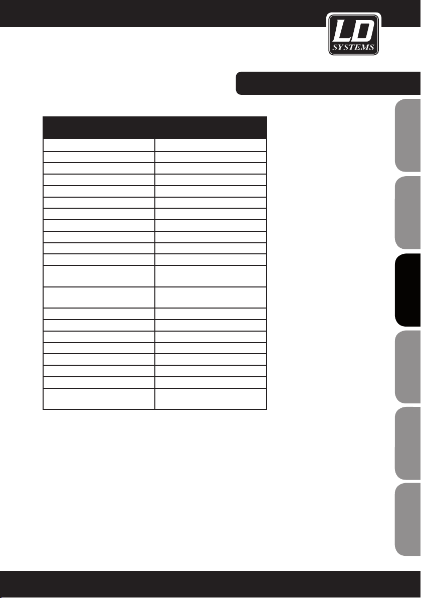
ÉMETTEUR DE POCHE (BODYPACk)
Référence : LDWS1G8BP
Modulation : FM
Gamme de fréquences HF : 1785 - 1800 MHz
Nombre de canaux : 192
Nombre de groupes : 16
Entrées : Mini-XLR 3 points
Réponse en fréquence: 50 - 16000 Hz
Taux de distorsion harmonique : < 0,8%
Rapport Signal/Bruit: > 90 dB
Puissance de sortie HF : 10 mW
Contrôles :
Indicateurs :
Alimentation: 2 piles LR06 (AA)
Autonomie : jusqu'à 13 h, selon les piles
Température de fonctionnement : -10°C … 45°C
Taux d'humidité relatif : 25% … 85%
Dimensions (L x H x P) : 65 x 90 x 24 mm
Poids (sans piles) 0,09 kg
Accessoires livrés : 2 x piles LR06 (AA)
Fonctionnalités:
Touche Power / Mute, Select,
sélecteur de gain 3 positions
Écran LCD multifonction, LED ASC,
LED Mute
Synchronisation des fréquences via
liaison infrarouge
CARACTÉRISTIqUES:
FRANCAISFRANCAIS FRANCAISFRANCAIS
FRANCAISDEUTSCHENGLISH
63
ITALIANopoLSKIESpAñoL
Page 64

CARACTÉRISTIqUES:
MICROPHONE
ENGLISHDEUTSCHFRANCAIS
ESpAñoLpoLSKIITALIANo
Référence: LDWS100MH1 LDWS100MH3
Type de microphone : serre-tête serre-tête
Capsule : à électret (statique) à électret (statique)
Directivité : cardioïde cardioïde
Réponse en fréquence: 20 - 20.000 Hz 70 - 16000 Hz
Connecteur : Mini-XLR 3 points Mini-XLR 3 points
Accessoires livrés : Bonnette mousse Bonnette mousse
Fonctionnalités:
LDHSAE1 LDWS100ML LDWS1000MW
serre-tête micro cravate
à électret (statique) à électret (statique) à électret (statique)
bidirectionnel cardioïde cardioïde
80 - 16000 Hz 20 - 20000 Hz 50 - 18000 Hz
Mini-XLR 3 points Mini-XLR 3 points Mini-XLR 3 points
Bonnette mousse Bonnette mousse Bonnette mousse
Anti-humidité
CâBLE GUITARE
microphone pour instruments à
vent
FRANCAISFRANCAIS FRANCAISFRANCAIS
64
Référence: LDWS100GC
Connecteur 1 : Mini-XLR 3 points
Connecteur 2 : Jack 6,35 mm
Longueur câble : 1,5 m
Page 65

DECLARATIONS DU FABRICANT :
GARANTIE LIMITÉE:
Cette garantie limitée s’applique aux produits de la marque Adam Hall, LD Systems, LD Premium, Defender, Palmer,
Cameo et Eminence.
Les droits inhérents à la garantie légale vis-à-vis du revendeur ne sont pas affectés par cette garantie. En fait elle
justifie d’une garantie supplémentaire indépendante auprès de la société Adam Hall.
La société Adam Hall garantit que le produit que vous avez acheté Adam Hall ou à l’un de ses revendeurs officiels,
est exempt de défaut matériel et d’usinage pour une durée de 2 ans (ou 3 ans pour les produits Palmer) à partir de
la date d’achat, lorsqu’il est utilisé dans des conditions normales.
La période de garantie limitée débute le jour de l’achat du produit. Pour bénéficier de cette garantie vous devez
produire une preuve d’achat sur laquelle figure la date d’achat du produit (ex : ticket de caisse daté, bon de
livraison daté…). Si un produit d´une des marques citées ci-dessus venait à nécessiter une réparation durant la
période de garantie limitée, vous aurez alors le droit de bénéficier des services de la garantie selon les termes et
conditions mentionnés par ce document.
Cette garantie limitée ne s’applique qu’à l’acheteur initial de ce produit Adam Hall et ne peut être en aucun cas
transférée à un tiers devenu propriétaire du produit. Durant la période de garantie limitée, Adam Hall s‘engage
à réparer ou remplacer les pièces défectueuses du produit. Toutes les pièces ou éléments démontés lors d‘une
réparation par Adam Hall deviennent la propriété d‘Adam Hall.
Dans le cas improbable d´un défaut récurrent, Adam Hall peut, à sa discrétion, décider de vous fournir un produit
de remplacement de son choix, dont les capacités techniques sont au moins équivalentes à celles de votre produit
initial.
FRANCAISFRANCAIS FRANCAISFRANCAIS
FRANCAISDEUTSCHENGLISH
Adam Hall ne garantit pas que le fonctionnement de ce produit sera exempt d‘erreur ou ininterrompu. Adam Hall ne
peut pas être rendu responsable des dégâts résultant de votre manquement à suivre les instructions d‘utilisation
fournies avec votre produit.
Cette garantie limitée ne s‘applique pas,
- aux pièces d‘usure (ex: piles)
- aux produits dont le numéro de série a été effacé ou aux produits endommagés ou rendus défectueux par
accident
- dans le cas d‘une utilisation non conforme aux conditions normales d‘utilisation, dans le cas d‘abus ou
toute autre cause externe
- dans le cas d‘un usage du produit en dehors des paramètres d‘utilisation stipulés dans la documentation
fournie avec le produit
- dans le cas de l‘usage de pièces de remplacement n‘étant pas fabriquées ou vendues par Adam Hall
- dans le cas d‘une modification du produit ou d‘une réparation par quiconque autre qu‘Adam Hall
Ces termes et conditions constituent l‘accord de garantie complet et exclusif entre vous et Adam Hall concernant
le produit de la marque Adam Hall que vous vous êtes procuré.
ITALIANopoLSKIESpAñoL
65
Page 66

DECLARATIONS DU FABRICANT :
LIMITATION OF LIABILITY
Si votre produit Adam Hall devait ne pas fonctionner correctement, votre seul et unique dédommagement sera
ENGLISHDEUTSCHFRANCAIS
la réparation du produit ou son remplacement. La responsabilité maximale imputable à Adam Hall dans le cadre
de cette garantie limitée se limite au montant le plus bas. Ce montant découle du prix d’achat du produit ou
bien du coût de la réparation ou des pièces de remplacement qui sont tombés en panne dans des conditions
d’utilisation normales.
Adam Hall n’est pas responsable des dommages causés par le produit ou par un dysfonctionnement du produit,
y compris les pertes de profits, les pertes d’épargne, et les conséquences inhérentes à ces dommages. La
responsabilité d’Adam Hall ne peut pas être engagée dans le cas d’une réclamation par un tiers ou dans le cas
d’une réclamation émanant de l’acheteur initial pour le compte d’un tiers.
Cette limitation de responsabilité est valable indépendamment du fait que les dommages commis fassent l’objet
de poursuites judiciaires, qu’ils fassent l’objet de réclamation (y compris pour négligence), de réclamations
contractuelles ou tout autre réclamation. Cette limitation de responsabilité ne peut être amendée ou dérogée par
quiconque. Elle est effective même si vous aviez avisé Adam Hall ou l’un de ses représentants officiels de la possibilité d’un tel dommage. Toutefois cette limitation de responsabilité est sans effet dans le cas de réclamations
pour dommages corporels.
Cette garantie limitée vous confère des droits légaux spécifiques. Selon votre pays, ou l’État dans lequel vous
vous trouvez, il est possible que vous disposiez d’autres droits. Veuillez consulter les lois applicables dans votre
pays ou votre État pour déterminer l’ensemble de vos droits.
FAIRE FONCTIONNER LA GARANTIE
Pour faire fonctionner la garantie sur ce produit, veuillez contacter Adam Hall ou le revendeur agréé auquel vous
avez acheté le produit.
ESpAñoLpoLSKIITALIANo
DECLARATION DE CONFORMITE CE
Ces appareils répondent aux exigences essentielles et aux autres dispositions pertinentes des directives 1999/5/
EC (R & TTE), 2004/108/EC (EMC) et 2006/95/EC (LVD). Pour plus d‘informations, consultez www.adamhall.com.
ELIMINATION CORRECTE DES DÉCHETS (DÉCHETS ÉLECTROMÉNAGERS)
(Applicable dans l’Union Européenne et dans les autres pays européens disposant d’un système de tri des déchets)
FRANCAISFRANCAIS FRANCAISFRANCAIS
Ce signe figurant sur le produit, ou dans la brochure jointe au produit, indique qu’il ne doit pas être jeté dans le
même bac à ordures que les déchets ménagers classiques lorsqu’il arrive en fin de vie. Pour écarter les risques
de pollution de l’environnement ou les risques d’intoxication humaine dûes à un mauvais traitement des déchets,
veuillez séparer ce produit des autres types de déchets. Il sera ainsi inséré dans la boucle du recyclage et ces
composants pourront être traités puis éventuellement réutilisés.
Nous recommandons aux particuliers de contacter leur revendeur local ou les autorités locales pour s’informer
de la meilleure façon de traiter les déchets électroménagers.
Les professionnels doivent contacter leur fournisseur et examiner avec lui les termes et conditions de leur
contrat d’achat. Ce produit ne doit pas être mélangé aux déchets industriels.
66
Page 67

DECLARATION WEEE
Votre produit LD-Systems a été développé et fabriqué avec des matériaux et des composants de haute qualité,
qui peuvent être recyclés et/ou réutilisés. Ce symbole indique que les appareils électriques et électroniques, à la
fin de leur durée de vie opérationnelle, doivent être gérés séparément des déchets ordinaires.
Veuillez apporter ce produit au point de collecte ou centre de recyclage local prévu pour de tels appareils. Vous
contribuerez ainsi à la protection de l'environnement dans lequel nous vivons tous.
BATTERIES ET ACCUMULATEURS
Les piles ou batteries rechargeable livrées avec l'appareil sont recyclables. Veuillez les jeter dans un bac à déchets spécial, ou déposez-les chez votre revendeur spécialisé. Pour une meilleure protection de l'environnement,
ne jetez les piles que lorsqu'elles sont épuisées.
FRANCAISFRANCAIS FRANCAISFRANCAIS
ÉCOLOGIE ET ÉCONOMIES D'ÉNERGIE :
Économiser l'électricité contribue à la protection de l'environnement. Pensez à éteindre les appareils électriques
dès que vous ne vous en servez pas. Pour éviter le gaspillage d'énergie en mode Standby (veille), débranchez le
cordon secteur de la prise murale lorsqu'un appareil n'est pas utilisé.
Adam Hall GmbH, tous droits réservés. Les caractéristiques techniques et les fonctions disponibles sur le produit
sont sujettes à modifications. La photocopie, la traduction et toute forme de copie, partielle ou intégrale, de ce
manuel utilisateur sont interdites.
FRANCAISDEUTSCHENGLISH
ITALIANopoLSKIESpAñoL
67
Page 68

ENGLISHDEUTSCHFRANCAIS
Gracias por elegir LD Systems!
Este producto se ha diseñado para ofrecer una fiabilidad y durabilidad óptima. Los productos de LD Systems se
caracterizan por su gran calidad, avalada por el prestigio de la marca y una dilatada experiencia como fabricante.
Le rogamos que lea atentamente estas instrucciones para familiarizarse rápidamente con este producto LD
Systems y aprovechar al máximo todas las funciones.
Si desea obtener información sobre LD Systems, visite nuestro sitio web WWW.LD-SYSTEMS.COM
Introducción
ESpAñoLpoLSKIITALIANo
El LD Systems WS1G8 es un avanzado sistema inalámbrico True Diversity de 192 canales UHF, que ofrece un
sonido natural, un gran margen dinámico, una excelente relación señal/ruido y unos valores bajos de THD en la
banda de 1.785 a 1.800 MHz. Ofrece una reproducción de sonido uniforme de 50 Hz a 16 kHz. Tanto el transmisor de micrófono como de petaca disponen de una pantalla LCD que muestra el canal, el grupo y el estado de la
batería. La búsqueda automática de canales, la sincronización de frecuencias por infrarrojos y la pantalla retroiluminada multifunción del receptor permiten configurar y operar fácilmente el sistema. La autonomía máxima es
de 13 horas con baterías de tipo AA de alta calidad.
FRANCAISFRANCAIS FRANCAISFRANCAIS
68
Page 69

LD WS1G8
SISTEMA INALÁMBRICO 192 CANALES UHF TRUE DIVERSITY
FRANCAISFRANCAIS FRANCAISFRANCAIS
FRANCAISDEUTSCHENGLISH
ITALIANOPOLSKIESPAÑOL
69
Page 70

MEDIDAS DE SEGURIDAD:
1. Lea detenidamente este manual.
2. Guarde el manual para poder consultarlo en el futuro.
3. Siga las instrucciones del manual.
ENGLISHDEUTSCHFRANCAIS
4. Tenga en cuenta las advertencias de seguridad. No quite las instrucciones de seguridad ni cualquier otra
información indicada en el equipo.
5. Utilice el equipo únicamente según la finalidad prevista.
6. Emplee un soporte y/o sistema de fijación estables y adecuados cuando instale el equipo de forma permanente. Asegúrese de que los soportes para pared están firmemente fijados. Asegúrese de que el equipo está
instalado de forma segura y no se puede caer.
7. Al instalar el equipo, respete las normas de seguridad aplicables en su país.
8. Evite colocar el equipo cerca de radiadores, acumuladores de calor o cualquier otra fuente de calor. Asegúrese
de que el equipo dispone de la suficiente ventilación y de que no se sobrecalentará.
9. No coloque velas encendidas, ni otras fuentes de llama, sobre el equipo.
10. No tape las rejillas de ventilación.
11. No utilice el equipo cerca del agua. No exponga este equipo a materiales, líquidos o gases inflamables.
12. Asegúrese de que el equipo no quede expuesto a goteras o salpicaduras de agua. No coloque recipientes
llenos de líquido, como floreros o copas, sobre el equipo.
13. Asegúrese de que no se caiga ningún objeto sobre el equipo.
14. Emplee el equipo únicamente con los accesorios recomendados por el fabricante.
15. ADVERTENCIA: Si el equipo tiene un conector de tierra, deberá enchufarse a una toma eléctrica con conexión
de protección a tierra. No desactivar nunca esta conexión de protección a tierra del cable eléctrico.
16. Si el equipo ha estado expuesto a un cambio brusco de temperatura (por ejemplo, después del transporte),
no lo encienda inmediatamente. La condensación o la humedad podrían dañar el equipo. Deje el equipo apagado hasta que haya alcanzado la temperatura ambiente.
17. No abra el equipo ni intente modificarlo.
18. Antes de conectar el equipo a la red eléctrica, asegúrese de que la tensión y frecuencia son las mismas
ESpAñoLpoLSKIITALIANo
que los valores indicados en el equipo (ver etiqueta de especificaciones). Si el equipo dispone de un selector de
tensión, antes de enchufarlo a la red eléctrica, asegúrese de que el valor seleccionado coincide con la tensión de
suministro.
Si el enchufe no encaja en la toma eléctrica, consulte a un electricista.
19. Asegúrese de que el cable eléctrico no está pinzado. Evite que el cable resulte pellizcado, sobre todo en los
extremos de conexión al equipo y en la toma eléctrica.
20. Para evitar accidentes y daños personales, compruebe que en toda la longitud del cableado no hay peligro de
FRANCAISFRANCAIS FRANCAISFRANCAIS
que provoque una caída, por ejemplo.
21. Al conectar el equipo, asegúrese de que haya una toma eléctrica accesible.
Desenchufe el equipo de la toma eléctrica cuando no esté en uso o antes de limpiarlo. Para desenchufarlo tire
del enchufe, no del cable eléctrico.
22. Evite encender y apagar el equipo en cortos intervalos de tiempo, ya que se reduce así la vida útil del equipo.
23. IMPORTANTE: Al sustituir los fusibles, utilice únicamente fusibles del mismo tipo y características. Si el
fusible se fundiera continuamente, póngase en contacto con un servicio técnico autorizado.
24. Para desconectar completamente el equipo de la tensión eléctrica, desenchúfelo de la toma eléctrica.
25. Si el equipo dispone de un enchufe eléctrico Volex, deberá desbloquearse el Volex del equipo para desenchufarlo. Esto implica que un tirón en el cable eléctrico puede desplazar el equipo y provocar daños personales o
70
Page 71

MEDIDAS DE SEGURIDAD:
materiales. Por tanto, asegúrese de instalar los cables con sumo cuidado.
26. Si es probable que caiga un rayo por una tormenta eléctrica o si no va a emplear el equipo durante mucho
tiempo, desenchufe el cable eléctrico.
27. Al transportar el equipo, para evitar daños personales o materiales, asegúrese de que no se pueda caer
accidentalmente.
28. Si el equipo no funciona correctamente, o si se ha vertido líquido sobre él, o si un objeto ha caído en su
interior o si ha sufrido algún desperfecto, apague inmediatamente el equipo y desenchufe el cable eléctrico.
Únicamente un técnico especialista debe reparar el equipo.
29. Emplee un paño seco para limpiar el equipo.
30. Siga las normas sobre reciclaje existentes en su país. Separe el plástico del papel y cartón.
31. No deje las bolsas de plástico al alcance de los niños.
ENGLISH
FRANCAISFRANCAIS FRANCAISFRANCAIS
CAUTION
RISK OF ELECTRIC SHOCK
DO NOT OPEN
ADVERTENCIA:
Para evitar el riesgo de descarga eléctrica, no retire la tapa (o el panel posterior). Este equipo no contiene piezas
que puedan ser reparadas por el usuario. Para cualquier tarea de mantenimiento o reparación, acuda a un
técnico cualificado.
El símbolo de rayo dentro de un triángulo equilátero advierte al
usuario de la presencia de tensión peligrosa sin aislamiento dentro de la carcasa del producto que
pueden ser de magnitud suficiente como para suponer un riesgo para las personas.
El símbolo de exclamación dentro de un triángulo equilátero advierte al usuario de la existencia de
importantes instrucciones de funcionamiento y mantenimiento (reparaciones) en la documentación
adjunta con el equipo.
ADVERTENCIA: ¡ALTO VOLUMEN!
Este sistema de transmisión se destina a un uso profesional. Por consiguiente, si se aplica a un uso comercial,
estará sujeto a las normas y reglamentos de la Asociación para la prevención de accidentes de su sector profesional. Como fabricante, Adam Hall tiene la obligación de informar formalmente a los usuarios de la existencia de
posibles riesgos para la salud.
Daños auditivos por exposición prolongada a un nivel SPL alto: el altavoz puede generar fácilmente un nivel de
presión sonora (SPL) lo suficientemente elevado como para causar daños auditivos permanentes a los artistas, el
personal de producción y el público. Deben tomarse precauciones para evitar la exposición prolongada a un SPL
de más de 90 dB.
FRANCAISDEUTSCHENGLISH
ITALIANOPOLSKIESPAÑOL
71
Page 72

COMPONENTES DEL SISTEMA E INSTALACIÓN:
LOS SISTEMAS DE UN RECEPTOR INCLUYEN
1 receptor simple WS1G8
1 transmisor WS1G8 (micrófono de mano o petaca con micrófono/cable de guitarra)
2 antenas
ENGLISHDEUTSCHFRANCAIS
1 adaptador de corriente
2 baterías de tipo AA
1 cable de audio
1 manual de usuario
1 estuche de transporte
LOS SISTEMAS DE DOBLE RECEPTOR INCLUYEN
1 receptor doble WS1G8
2 transmisores WS1G8 (micrófono de mano o petaca con micrófono/cable de guitarra)
2 antenas
1 adaptador de corriente
4 baterías de tipo AA
1 cable de audio
1 kit de rack (2 soportes de montaje en rack, 2 cables TNC, 2 adaptadores TNC, 2 placas ciegas, 1 juego de
tornillos)
1 manual de usuario
1 estuche de transporte
INSTALACIÓN
Para mejorar la recepción, sitúe el receptor a una altura mínima de 1m y disponga las antenas hacia arriba y
en forma de V. Asegúrese de que los transmisores y los receptores tienen línea visual directa y de que hay una
distancia mínima de 50cm entre las antenas receptoras y los objetos metálicos más cercanos. No instale los
ESpAñoLpoLSKIITALIANo
receptores cerca de equipos controlados digitalmente.
FRANCAISFRANCAIS FRANCAISFRANCAIS
72
Page 73

PANEL fRONTAL Y POSTERIOR DEL
WS1G8R:
6
5
87
1
BOTÓN POwER (ENCENDIDO/APAGADO)
Manténgalo pulsado durante 1 segundo
2
BOTÓN SET
Manténgalo pulsado durante 1 segundo para
acceder al menú
3
VOLUMEN / VALOR
Botones ARRIBA y ABAJO
4
BOTÓN ASC
Sincronización de frecuencia por infrarrojos
2
3 1 1
4
9
5
PUERTO DE INfRARROjOS
6
LEDS DE ANTENA A O B
Indica la entrada de antena activa (A o B)
7
VúMETRO DE 6 SEGMENTOS DEL NIVEL DE Rf
(RADIOfRECUENCIA) DE LAS ANTENAS A Y B.
8
VúMETRO DE 7 SEGMENTOS DEL NIVEL DE
AUDIO
9
PANTALLA MULfUNCIONAL ILUMINADA
2
3
4
1
FRANCAISFRANCAIS FRANCAISFRANCAIS
FRANCAISDEUTSCHENGLISH
1
CONECTORES TNC DE LAS ANTENAS A Y B.
2
SALIDA XLR BALANCEADA.
3
SALIDA POR jACk DE 6,3 MM NO BALANCEADA.
4
TOMA DE ALIMENTACIÓN. UTILICE úNICAMENTE EL ADAPTADOR DE CORRIENTE SUMINISTRADO.
ITALIANOPOLSKIESPAÑOL
73
Page 74

PANEL fRONTAL Y POSTERIOR DEL WS1G8R2:
VOLUMEAUTO
L
VOLUME
L
AUTO
ENGLISHDEUTSCHFRANCAIS
1
1
2
3
4
5
ESpAñoLpoLSKIITALIANo
6
L
VOLUMEAUTO
7 8 9
BOTÓN DE ENCENDIDO/APAGADO
BOTÓN SET
Manténgalo pulsado durante 1 segundo para
acceder al menú
VOLUMEN / VALOR
Botones ARRIBA y ABAJO
BOTÓN ASC
Sincronización de frecuencia por infrarrojos
PUERTO DE INfRARROjOS
2
4
L
VOLUME
3 5
6
LEDS DE ANTENA A O B
AUTO
Indica la entrada de antena activa (A o B)
7
VúMETRO DE 6 SEGMENTOS DEL NIVEL DE Rf
(RADIOfRECUENCIA) DE LAS ANTENAS A Y B
8
VúMETRO DE 7 SEGMENTOS DEL NIVEL DE
AUDIO
9
PANTALLA MULfUNCIONAL ILUMINADA
10
SALIDA DE AURICULARES
Jack estéreo de 6,3 mm
11
VOLUMEN DE AURICULARES
10 11
FRANCAISFRANCAIS FRANCAISFRANCAIS
74
1 5 4 3 2 6 1
1
CONECTORES TNC DE LAS ANTENAS A Y B
2
SALIDA XLR BALANCEADA CANAL 1
3
SALIDA XLR BALANCEADA CANAL 2
4
SALIDA XLR BALANCEADA MEZCLA
Esta salida es una mezcla de ambas señales de
audio de los receptores. Puede ajustarse independientemente el control de volumen del frontal de
cada receptor.
5
SALIDA jACk DE 6,3 MM NO BALANCEADA
MEZCLA
Esta salida es una mezcla de ambas señales de
audio de los receptores. Puede ajustarse independientemente el control de volumen del frontal de
cada receptor.
6
TOMA DE ALIMENTACIÓN. UTILICE úNICAMENTE EL ADAPTADOR DE CORRIENTE SUMINISTRADO
Page 75
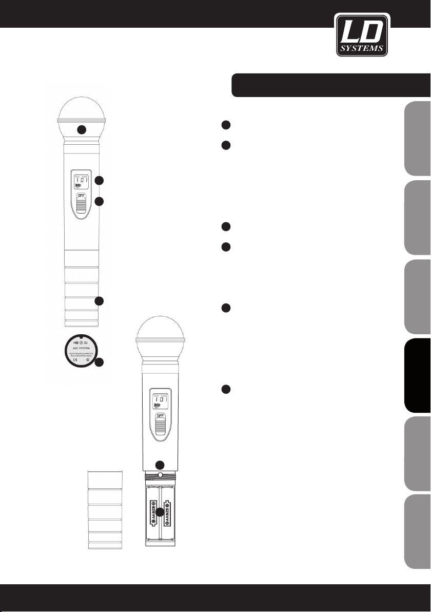
MICRÓfONO DE MANO:
1
1
2
3
5
6
CABEZA DEL MICRÓfONO
2
PANTALLA LCD RETROILUMINADA
Muestra el grupo, el canal y el estado de batería
con un indicador de 4 segmentos. Sustituya
inmediatamente las baterías cuando parpadee el
símbolo de batería.
NOTA: La retroiluminación se apagará automáticamente al cabo de unos instantes.
3
INTERRUPTOR DE ENCENDIDO
4
CONTROL DE GANANCIA
¡Ajuste con cuidado! ¡Emplee sólo un destornillador apropiado!
Gire a la izquierda para disminuir la ganancia, o a
la derecha para aumentarla.
5
COMPARTIMENTO DE LAS BATERíAS
Para sustituir las baterías, desenrosque la tapa en
sentido antihorario, quite las baterías, inserte 2
baterías nuevas de tipo AA (polaridad indicada en
el compartimento) y vuelva a enroscar la tapa en
sentido horario en el micrófono de mano. Asegúrese de que la tapa la tapa está bien apretada.
FRANCAISFRANCAIS FRANCAISFRANCAIS
FRANCAISDEUTSCHENGLISH
6
PUERTO DE INfRARROjOS IR
Ubicado en la parte inferior del micrófono de
mano.
Para sincronizar la frecuencia, pulse el botón
ASC del receptor (el símbolo ASC de la pantalla
parpadeará) y mantenga el transmisor (encendido)
con su puerto de infrarrojos apuntando directa-
4
5
mente al puerto de infrarrojos del receptor a una
distancia entre 5 y 20 cm.
ITALIANOPOLSKIESPAÑOL
75
Page 76

TRANSMISOR DE PETACA:
1
BOTÓN DE ENCENDIDO, APAGADO Y SILENCIO
Manténgalo pulsado durante 2 segundos para
ENGLISHDEUTSCHFRANCAIS
ESpAñoLpoLSKIITALIANo
apagar o encender el equipo.
Púlselo brevemente para silenciar el equipo.
Púlselo brevemente de nuevo para desactivar la
función Silencio.
2
PANTALLA LCD RETROILUMINADA
Muestra el grupo, el canal y el estado de batería
con un indicador de 3 segmentos. Sustituya
inmediatamente las baterías cuando parpadeen
el símbolo de batería y el LED ASC. Nota: La retroiluminación se apagará automáticamente al cabo
de unos instantes.
3
ANTENA
4
LED ASC
Iluminado en verde de forma fija si el equipo está
encendido.
Parpadea en verde durante la sincronización de
frecuencia.
Parpadea en verde si las baterías están descargadas.
5
LED MUTE
Se ilumina en color rojo si la función Silencio está
activada.
3
2
1
7
4
5
8
6
FRANCAISFRANCAIS FRANCAISFRANCAIS
76
6
COMPARTIMENTO DE LAS BATERíAS
Para sustituir las baterías, presione ligeramente
las posiciones marcadas en los laterales de la
tapa para abrirla. Quite las baterías, inserte 2
baterías nuevas de tipo AA (polaridad indicada en
el compartimento) y cierre la tapa.
7
PUERTO DE INfRARROjOS IR
Para sincronizar la frecuencia, abra la tapa, pulse
el botón ASC del receptor (el símbolo ASC de la
pantalla parpadeará) y mantenga el transmisor
(encendido) con su puerto de infrarrojos apuntando directamente al puerto de infrarrojos del
receptor a una distancia entre 5 y 20 cm.
8
SELECT
Configuración manual de un grupo de canales.
Abra la tapa, mantenga pulsado el botón hasta
que se muestre el número de grupo. Suelte el
botón. El número de grupo parpadeará. A continuación, pulse el botón repetidamente hasta que
se muestre el grupo deseado. Realice el mismo
procedimiento para cambiar el número de canal.
Si no pulsa ningún botón durante un breve periodo
de tiempo, la pantalla vuelve automáticamente al
menú principal.
Page 77

9
INPUT
Entrada mini XLR de 3 pines para el micrófono o
cable de guitarra suministrados.
10
CONMUTADOR DE GANANCIA
Seleccione la ganancia adecuada.
MIC = micrófono
0dB = guitarra con pastilla pasiva
-10dB = guitarra con pastilla activa
Si la señal de audio satura al receptor, cambie la
ganancia al siguiente valor inferior.
11
CLIP DE CINTURÓN
Cuelgue la petaca del cinturón o de la cinta de la
guitarra, como se indica en la figura.
TRANSMISOR DE PETACA:
9
11
10
FRANCAISFRANCAIS FRANCAISFRANCAIS
FRANCAISDEUTSCHENGLISH
PINEADO DEL MINI XLR DE LA PETACA
MINI XLR
2
1
3
Guitarra, bajo y otras fuentes de alta impedancia
jack de 6,3 mm
malla punta
MINI XLR
R
2,2K
2
1
3
Micro de diadema, Lavalier o de instrumento de viento con salida de baja sensibilidad. Una resistencia de 2K2 soldada entre los pines 2 y 3 aumenta la ganancia.
MINI XLR
2
1
3
Micro de diadema, Lavalier o de instrumento de
viento
ITALIANOPOLSKIESPAÑOL
77
Page 78
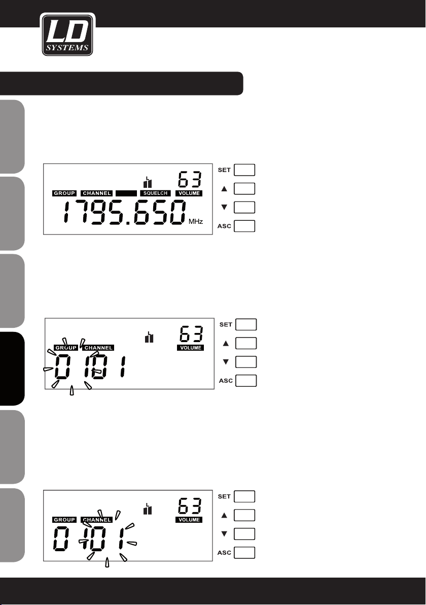
CONfIGURACIÓN DEL SISTEMA:
PANTALLA PRINCIPAL
La pantalla principal muestra los valores preseleccionados de frecuencia, configuración de la función Silenciador
y volumen.
VOLUME
Pulse los botones ARRIBA y ABAJO para ajustar el volumen (00 a 63).
ENGLISHDEUTSCHFRANCAIS
AUTO
GROUP
Mantenga pulsado el botón SET durante 1 segundo. Parpadearán GROUP y los 2 primeros dígitos. Pulse los
botones ARRIBA y ABAJO para establecer el número de grupo (01 a 16). Pulse SET para confirmar.
Si no pulsa ningún botón durante un breve periodo de tiempo, la pantalla vuelve automáticamente al menú
principal.
NOTA: Cada uno de los grupos de 01 a 16 tiene 12 canales con su propia frecuencia.
ESpAñoLpoLSKIITALIANo
CHANNEL
Mantenga pulsado el botón SET durante 1 segundo y luego pulse SET de nuevo. Parpadearán CHANNEL y los 2
primeros dígitos. Pulse los botones ARRIBA y ABAJO para establecer el número de canal (01 a 12). Pulse SET
para confirmar.
Si no pulsa ningún botón durante un breve periodo de tiempo, la pantalla vuelve automáticamente al menú
FRANCAISFRANCAIS FRANCAISFRANCAIS
principal.
Una vez seleccionada la frecuencia (grupo y canal), será necesario sincronizar el transmisor (micro de mano o
petaca) a la misma frecuencia (grupo y canal) mediante la función ASC.
78
Page 79
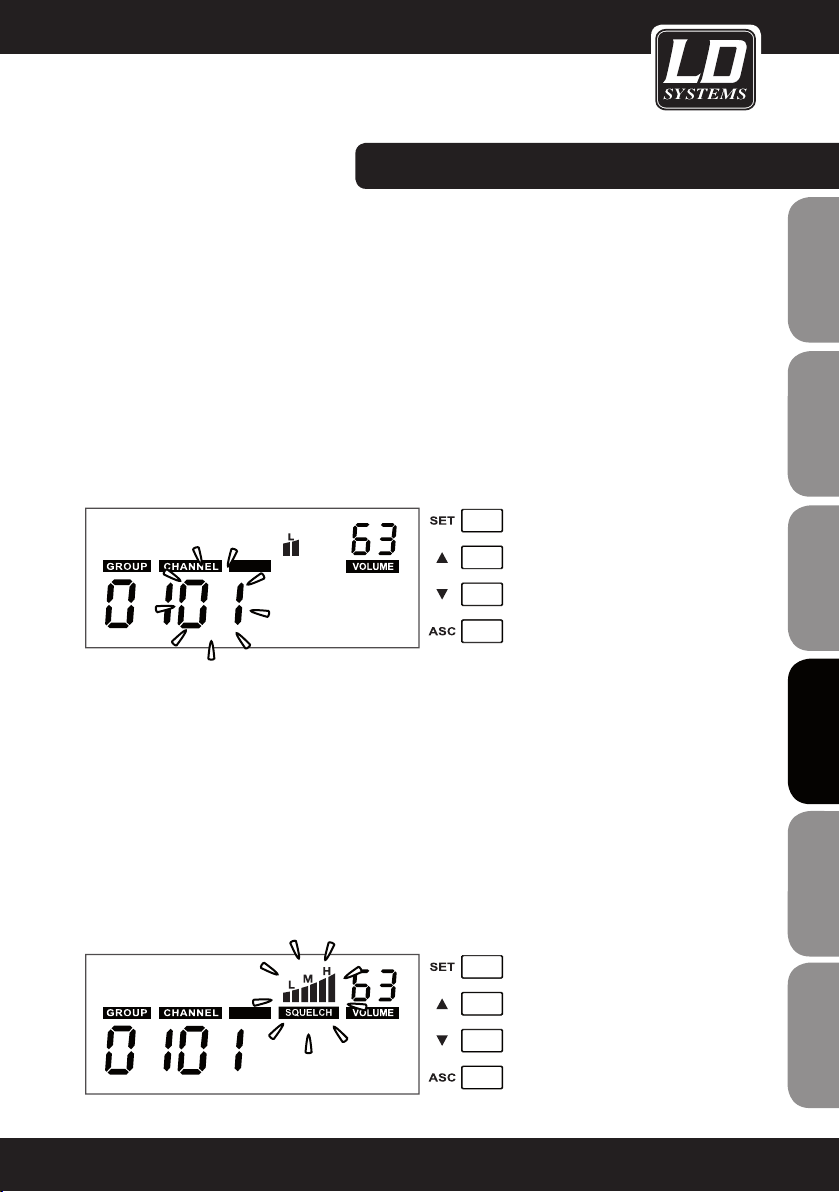
CONfIGURACIÓN DEL SISTEMA:
fUNCIÓN ESCÁNER DE CANALES
Mantenga pulsado el botón SET durante 1 segundo y luego pulse SET 2 veces. Parpadearán CHANNEL, AUTO y
los 2 primeros dígitos. Pulse los botones ARRIBA y ABAJO para iniciar el escáner de canales. Una vez terminado
el escaneo, la pantalla mostrará automáticamente los canales que no tienen interferencias.
Cuando se emplean varios sistemas, para realizar el escaneo de canales los sistemas ya configurados deben
estar encendidos. La función de escaneo de frecuencias buscará en las frecuencias del grupo preseleccionado
(01 a 16).
La precisión del escaneo depende del entorno y del número de sistemas inalámbricos simultáneos. Si el escáner
detecta como libre una frecuencia que ya está siendo usada, reinicie el proceso hasta que se detecte una
frecuencia libre.
Nota: Cuando haya varios sistemas funcionando, todos los canales de frecuencia deben pertenecer al mismo
grupo (01 a 16).
Importante: En la misma ubicación, no debería funcionar simultáneamente más de un sistema inalámbrico en la
misma frecuencia, ya que la interferencia produciría un ruido elevado.
AUTO
SILENCIADOR (SqUELCH)
La función squelch elimina el ruido no deseado cuando el transmisor está apagado. También elimina la señal de
un transmisor cuando no transmite con la suficiente potencia para llegar al receptor.
Ajuste este nivel (con el transmisor apagado) al mínimo posible con tal de que elimine el ruido. En general, se
recomienda el valor “L”. Si selecciona el valor “H” puede causar una distancia menor de la ruta de transmisión
en condiciones desfavorables.
Mantenga pulsado el botón SET durante 1 segundo y luego pulse SET 3 veces. Parpadearán SQUELCH y los
símbolos que tiene encima. Pulse los botones ARRIBA y ABAJO para seleccionar el valor L = Low (bajo), M = Mid
(intermedio) o H = High (alto). Pulse SET para confirmar.
Si no pulsa ningún botón durante un breve periodo de tiempo, la pantalla vuelve automáticamente al menú
principal.
ADVERTENCIA: Antes de cambiar la función Squelch, ponga al mínimo el volumen del sistema de audio conectado.
FRANCAISFRANCAIS FRANCAISFRANCAIS
FRANCAISDEUTSCHENGLISH
AUTO
ITALIANOPOLSKIESPAÑOL
79
Page 80

CONfIGURACIÓN DEL SISTEMA:
ASC (sincronización de frecuencia por infrarrojos)
Las frecuencias de transmisión del transmisor y el receptor de un sistema inalámbrico tienen que coincidir.
Una vez seleccionada la frecuencia (grupo y canal), será necesario sincronizar el transmisor (micro de mano o
petaca) a la misma frecuencia (grupo y canal) mediante la función ASC.
ENGLISHDEUTSCHFRANCAIS
Pulse el botón ASC
(encendido) con su puerto de infrarrojos
distancia entre 5 y 20 cm. El proceso de sincronización terminará en unos momentos, y el medidor de nivel de
3
señal RF
ESpAñoLpoLSKIITALIANo
1
del receptor (el símbolo ASC de la pantalla parpadeará) y mantenga el transmisor
del receptor indicará presencia de señal.
2
2
apuntando directamente al puerto de infrarrojos del receptor a una
2
1
LOw BATT (Batería baja)
FRANCAISFRANCAIS FRANCAISFRANCAIS
Si el indicador „LOW BATT“ parpadea en la pantalla del receptor sustituya inmediatamente las baterías del transmisor..
80
3
Page 81
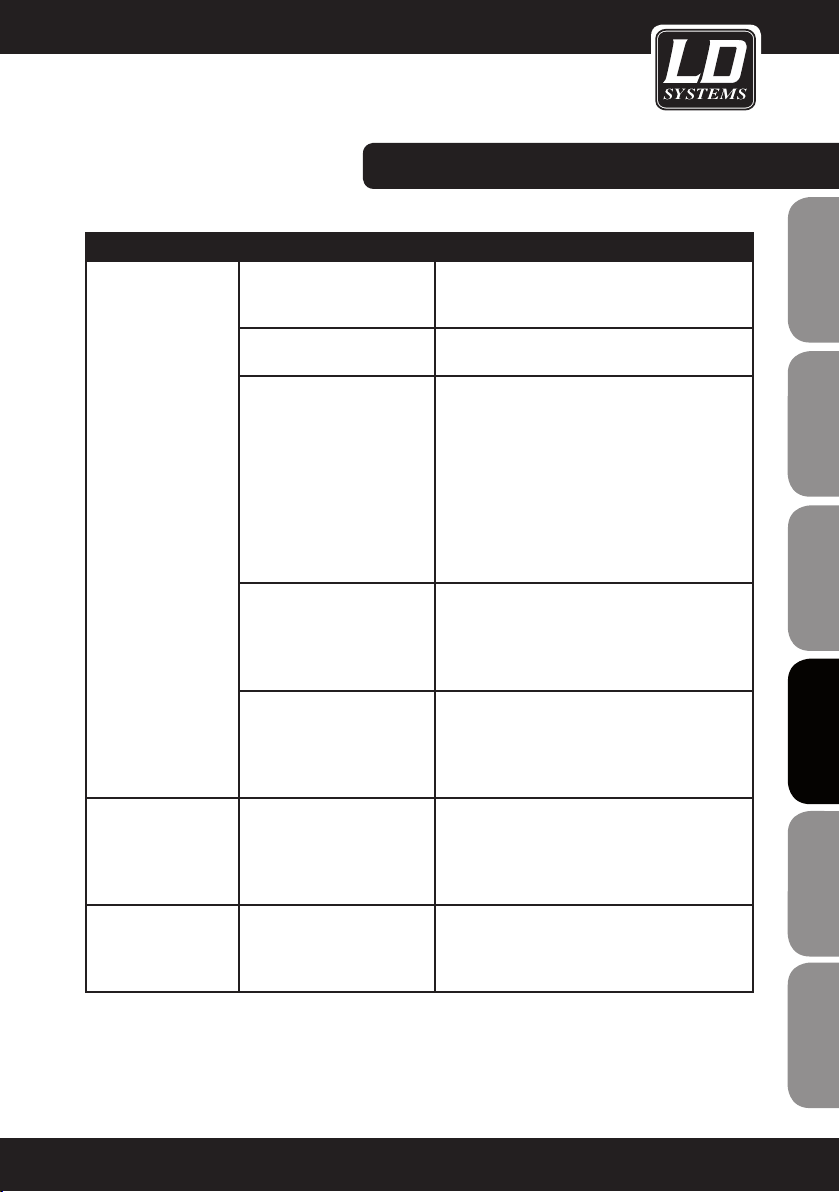
RESOLUCIÓN DE PROBLEMAS:
PROBLEMA PANTALLA SOLUCIÓN
No hay sonido o el
volumen es muy bajo.
Hay distorsión o mucho
ruido.
El sonido está distor
sionado.
Transmisor: La pantalla está
apagada.
Receptor: La pantalla está
apagada.
Receptor: El indicador RF está
apagado.
Transmisor: Está encendido.
Receptor: El indicador RF se
ilumina.
Transmisor de petaca: La
pantalla está encendida, y el
LED Mute se ilumina.
Receptor: El indicador RF se
ilumina.
Receptor: El indicador RF se
ilumina.
-
Transmisor: Parpadea el
símbolo de batería.
Receptor: El nivel AF marcado
por el vúmetro es muy alto.
Asegúrese de que el transmisor está encendido.
Asegúrese de que las baterías no están descar
gadas.
Compruebe la conexión de la alimentación eléctrica.
Enciéndalo.
Comprueba que el transmisor y el receptor tienen
configurada la misma frecuencia.
Disminuya la distancia entre el transmisor y el
receptor.
Compruebe que el transmisor y el receptor tengan
línea directa visual.
Asegúrese de que las antenas del receptor están
conectadas y colocadas hacia arriba en forma de V.
Desactive la función Mute.
Suba el volumen del receptor.
Suba la ganancia del transmisor.
Compruebe la conexión de audio del receptor y de
la mesa de mezclas.
Compruebe la configuración de la mesa de mezclas.
Elimine posibles causas de interferencia (equipos
controlados digitalmente, otros sistemas inalámbricos cercanos).
Configure el sistema inalámbrico en otra frecuencia
de transmisión.
Sustituya las baterías
Disminuya la ganancia del transmisor.
-
FRANCAISFRANCAIS FRANCAISFRANCAIS
FRANCAISDEUTSCHENGLISH
ITALIANOPOLSKIESPAÑOL
81
Page 82

INSTALACIÓN EN RACK:
EL kIT DE MONTAjE EN RACk LDwS100Rk (OPCIONAL) PARA 1 RECEPTOR LDwS1G8 INCLUYE:
2 SOPORTES DE RACk, 2 CABLES TNC, 2 ADAPTADORES TNC Y UN jUEGO DE TORNILLOS
ENGLISHDEUTSCHFRANCAIS
EL kIT DE MONTAjE EN RACk LDwS100Rk2 (OPCIONAL) PARA 2 RECEPTORES LDwS1G8 INCLUYE:
1 ADAPTADOR A RACk DE 19" Y UN jUEGO DE TORNILLOS
ESpAñoLpoLSKIITALIANo
FRANCAISFRANCAIS FRANCAISFRANCAIS
82
Page 83

CARACTERíSTICAS TÉCNICAS:
RECEPTOR
Modelo: LDWS1G8R LDWS1G8R2
Tipo de receptor: True Diversity
Modulación: FM
Banda de frecuencias: 1.785 a 1.800 MHz
Canales: 192 (16 x 12)
Grupos: 16
Conectores de antena: 2 TNC
Respuesta en frecuencia: 50 a 16.000 Hz
Silenciador (Squelch): Low, Mid, High
Optimización de transmisión: Tono piloto
THD: <0,8%
Relación señal a ruido: >90 dB
Salida balanceada: XLR 2 XLR
Salida balanceada de mezcla: XLR
Salida no balanceada: jack de 6,3 mm
Salida no balanceada de mezcla: jack de 6,3 mm
Salida de auriculares: Jack estéreo de 6,3 mm
Nivel de salida de audio (balan-
ceado):
Nivel de salida de audio (no
balanceado):
Controles: POWER, SET, ARRIBA, ABAJO, ASC
Indicadores:
Tensión eléctrica: 12 a 18 VDC, 500 mA 12 a 18 VDC, 1000 mA
Rango de temperatura operativa: -10 °C a 45 °C
Humedad relativa operativa: 25% a 85%
Dimensiones (An x Al x F): 212 x 45 x 163 mm 483 x 45 x 163
Peso: 0,92 kg 2,24 kg
Accesorios incluidos:
Características: escáner de canal, sincronización de frecuencia por infrarrojos
Pantalla LCD multifuncional, nivel
de antena RF A/B, nivel de audio
adaptador de corriente, 2 antenas,
cable de audio
+6dBu
0dBu
POWER, 2 SET, 2 ARRIBA, 2 ABAJO,
2 ASC, volumen de auriculares
2 pantallas LCD multifuncional, 2
niveles de antena RF A/B, 2 niveles
de audio
adaptador de corriente, 2 antenas,
cable de audio, kit de montaje en
rack
FRANCAISFRANCAIS FRANCAISFRANCAIS
FRANCAISDEUTSCHENGLISH
ITALIANOPOLSKIESPAÑOL
83
Page 84

CARACTERíSTICAS TÉCNICAS:
MICRÓfONO DE MANO TRANSMISOR
ENGLISHDEUTSCHFRANCAIS
ESpAñoLpoLSKIITALIANo
Modelo: LDWS1G8MD LDWS1G8MC
Modulación: FM
Banda de frecuencias: 1.785 a 1.800 MHz
Canales: 192 (16 x 12)
Grupos: 16
Tipo de micrófono: dinámico condensador
Patrón polar: cardioide cardioide
Respuesta en frecuencia: 50 a 16.000 Hz
THD: <0,8%
Relación señal a ruido: >90 dB
Potencia de salida RF: 10 mW
Controles: Botón de encendido/apagado
Indicadores: pantalla LCD multifuncional
Alimentación: 2 baterías de tipo AA
Autonomía: hasta 13 horas (en función de las baterías)
Rango de temperatura operativa: -10 °C a 45 °C
Humedad relativa operativa: 25% a 85%
Dimensiones (L x Ø): 245 x 51 mm
Peso: 0,34 kg
Accesorios incluidos: 2 baterías de tipo AA
Características: sincronización de frecuencia por infrarrojos
FRANCAISFRANCAIS FRANCAISFRANCAIS
84
Page 85

CARACTERíSTICAS TÉCNICAS:
TRANSMISOR DE PETACA
Modelo: LDWS1G8BP
Modulación: FM
Banda de frecuencias: 1.785 a 1.800 MHz
Canales: 192
Grupos: 16
Entrada: mini XLR de 3 pines
Respuesta en frecuencia: 50 a 16.000 Hz
THD: <0,8%
Relación señal a ruido: >90 dB
Potencia de salida RF: 10 mW
Controles:
Indicadores:
Alimentación: 2 baterías de tipo AA
Autonomía:
Rango de temperatura operativa: -10 °C a 45 °C
Humedad relativa operativa: 25% a 85%
Dimensiones (An x Al x F): 65 x 90 x 24 mm
Peso (sin baterías): 0,09 kg
Accesorios incluidos: 2 baterías de tipo AA
Características:
Botón de encendido, Mute,
Selección
pantalla LCD multifuncional, LED
ASC, LED Mute
hasta 13 horas (en función de las
baterías)
sincronización de frecuencia por
infrarrojos
FRANCAISFRANCAIS FRANCAISFRANCAIS
FRANCAISDEUTSCHENGLISH
ITALIANOPOLSKIESPAÑOL
85
Page 86

CARACTERíSTICAS TÉCNICAS:
MICRÓfONO
ENGLISHDEUTSCHFRANCAIS
ESpAñoLpoLSKIITALIANo
Modelo: LDWS100MH1 LDWS100MH3
Tipo de micrófono: diadema diadema
cápsula: condensador back electret condensador back electret
Patrón polar: cardioide cardioide
Respuesta en frecuencia: 20 a 20.000 Hz 70 a 16.000 Hz
Conector: mini XLR de 3 pines mini XLR de 3 pines
Accesorios incluidos: bola antiviento bola antiviento
Características:
LDHSAE1 LDWS100ML LDWS1000MW
diadema micrófono Lavalier micrófono de instrumento de viento
condensador back electret condensador back electret condensador back electret
bidireccional cardioide cardioide
80 a 16.000 Hz 20 a 20.000 Hz 50 a 18.000 Hz
mini XLR de 3 pines mini XLR de 3 pines mini XLR de 3 pines
bola antiviento bola antiviento bola antiviento
resistente al agua
CABLE DE GUITARRA
FRANCAISFRANCAIS FRANCAISFRANCAIS
86
Modelo: LDWS100GC
Conector 1: mini XLR de 3 pines
Conector 2: jack de 6,3 mm
Longitud: 1,5 m
Page 87

DECLARACIÓN DEL FABRICANTE:
GARANTÍA LIMITADA
Esta garantía limitada se aplica a los productos de la marca Adam Hall, LD Systems, Defender, Palmer, Cameo y
Eminence.
No afecta a los derechos de garantía legal que asume el vendedor. De hecho, le concede al usuario derechos
adicionales ante Adam Hall, independientes de la garantía legal.
Adam Hall garantiza que el producto que ha adquirido de Adam Hall o de cualquier distribuidor autorizado de
Adam Hall estará exento de defectos de material y mano de obra, en condiciones normales de uso, durante un
período de 2 o 3 años a partir de la fecha de compra.
La garantía limitada entra en vigor el día de la fecha de compra. Para tener derecho a esta garantía será
necesario presentar un justificante de compra válido en el que figure la fecha de compra del producto, por
ejemplo, la factura o el albarán de entrega. Si el producto que ha adquirido necesitara una reparación durante
la vigencia de la garantía limitada, tendrá derecho a obtener los servicios de garantía conforme a los términos y
condiciones establecidos en este documento.
Esta garantía limitada se aplica únicamente al comprador original de este producto de Adam Hall y no se puede
transferir a terceras personas a las que el comprador haya cedido la propiedad del producto. Durante el periodo
de garantía limitada, Adam Hall se compromete a reparar o sustituir las piezas defectuosas del producto. Todas
las piezas o componentes retirados durante la reparación pasarán a ser propiedad de Adam Hall.
En el caso poco probable de que se produzca un fallo recurrente en el producto adquirido, Adam Hall, a su
entera discreción, podrá optar por sustituir dicho producto por otro de similares características.
FRANCAISFRANCAIS FRANCAISFRANCAIS
FRANCAISDEUTSCHENGLISH
Adam Hall no garantiza el funcionamiento ininterrumpido y sin fallos de este producto. Adam Hall no se hace
responsable de los posibles daños ocasionados por no seguir las instrucciones de uso suministradas con el
producto Adam Hall.
Esta garantía limitada no se aplica:
- en caso de desgaste normal de los consumibles (baterías, etc.)
- a los productos cuyo número de serie ha sido borrado, o que han quedado dañados y defectuosos debido a un
accidente
- en caso de defectos ocasionados por una incorrecta utilización o manipulación, o cualquier otra causa ajena
- en caso de utilización del producto no conforme con los parámetros establecidos en la documentación facilitada con el producto
- en caso de utilización de piezas de repuesto no fabricadas o vendidas por Adam Hall
- si el producto ha sido modificado o reparado por personal no autorizado por Adam Hall
Estos términos y condiciones constituyen el acuerdo de garantía íntegro y exclusivo entre usted y Adam Hall en
relación con el producto Adam Hall que acaba de adquirir.
ITALIANOPOLSKIESPAÑOL
87
Page 88

DECLARACIÓN DEL FABRICANTE:
LIMITACIÓN DE RESPONSABILIDAD
Si su producto Adam Hall no funciona de acuerdo con las garantías mencionadas arriba, tendrá derecho exclusivamente a la reparación o sustitución del mismo. La responsabilidad máxima de Adam Hall en virtud de los términos de esta garantía está limitada al menor importe que resulte del precio de compra del producto, del coste
ENGLISHDEUTSCHFRANCAIS
de la reparación o la sustitución de las piezas que han dejado de funcionar en condiciones normales de uso.
Adam Hall no será responsable de cualquier daño causado por el producto o por el mal funcionamiento del
producto, incluidas la pérdida de ganancias, la pérdida de ahorros o cualquier consecuencia derivada de dichas
pérdidas. Adam Hall no se hará responsable de ninguna reclamación presentada por un tercero o por el comprador inicial en nombre de un tercero.
Esta limitación de responsabilidad se aplicará con independencia de que se solicite una indemnización por daños
y perjuicios, o se presenten reclamaciones por negligencia, contractuales o de cualquier otra índole, y no podrá
ser derogada o modificada. Esta limitación de responsabilidad será efectiva incluso en el caso de que el comprador hubiese avisado previamente a Adam Hall o a alguno de sus representantes de la posibilidad de reclamar
daños y perjuicios. No obstante, esta limitación de responsabilidad no tendrá efecto en caso de reclamación por
daños personales.
Esta garantía limitada le otorga derechos legales específicos. Puede que posea derechos adicionales conforme a
la legislación del país o Estado en el que se encuentre. Le recomendamos que consulte la legislación vigente en
su país o Estado para conocer el alcance de sus derechos.
APLICACIÓN DE LA GARANTíA
Para solicitar asistencia técnica en relación con el producto en garantía, póngase en contacto con Adam Hall o
con el distribuidor autorizado donde adquirió el producto.
ESpAñoLpoLSKIITALIANo
DECLARACIÓN CE DE CONFORMIDAD
Estos dispositivos cumplen con los requisitos esenciales y otras disposiciones pertinentes de las Directivas 1999/5/
EC (R & TTE), 2004/108/EC (EMC) y 2006/95/EC (LVD). Para más información, consulte www.adamhall.com.
ELIMINACIÓN CORRECTA DE ESTE PRODUCTO (DESECHOS ELÉCTRICOS)
(Aplicable en la Unión Europea y en los países europeos que dispongan de un sistema de recogida selectiva)
El símbolo que aparece sobre el producto o en la documentación adjunta indica que, al final de su vida útil,
FRANCAISFRANCAIS FRANCAISFRANCAIS
no deberá desecharse con los demás residuos domésticos. Para evitar posibles efectos negativos en el medio
ambiente y en la salud humana debidos al vertido incontrolado de desechos, no mezcle este producto con los
demás residuos. La recogida selectiva ayuda a su posterior reciclaje y fomenta la reutilización sostenible de los
componentes de este equipo.
Si usted es un particular, deberá ponerse en contacto con el distribuidor donde adquirió este producto, o con el
ayuntamiento, para informarse sobre el reciclaje adecuado de este equipo.
Si usted es una empresa, deberá ponerse en contacto con su proveedor e informarse sobre los términos y condiciones de su contrato de compra-venta. Este producto no debe mezclarse con otros residuos industriales.
88
Page 89

DECLARACIÓN SOBRE WEEE
Este producto LD-Systems se ha desarrollado y fabricado con materiales y componentes de alta calidad que se
pueden reciclar o reutilizar. Este símbolo indica que los equipos eléctricos y electrónicos deben separarse del
resto de residuos comunes al final de su vida útil.
Para desechar este producto, llévelo al punto de recogida municipal o al centro de reciclaje específico para este
tipo de equipos. De este modo, contribuirá a proteger el medioambiente.
PILAS Y ACUMULADORES
Las pilas suministradas o las pilas recargables se pueden reciclar. Para desecharlas, deposítelas en un contenedor especial o entréguelas a su proveedor especializado. Para proteger el medioambiente, deseche sólo pilas
gastadas.
ECOLOGíA Y AHORRO ENERGÉTICO
Ahorre energía eléctrica para proteger el medio ambiente. Para ello, apague todos los aparatos eléctricos
cuando no estén en uso. Además, para evitar el consumo de energía en modo inactivo, desconecte todo aparato
eléctrico de la toma de corriente cuando no esté en uso.
FRANCAISFRANCAIS FRANCAISFRANCAIS
FRANCAISDEUTSCHENGLISH
Adam Hall GmbH. Todos los derechos reservados. Los datos técnicos y las características funcionales del producto están sujetos a modificaciones. Se prohíbe la fotocopia, traducción y cualquier otra forma de reproducción
parcial o total de este manual de usuario.
ITALIANOPOLSKIESPAÑOL
89
Page 90

ENGLISHDEUTSCHFRANCAIS
Dziękujemy za wybór LD Systems!
Zaprojektowaliśmy ten produkt tak, aby działał sprawnie przez wiele lat. LD Systems gwarantuje wysoką jakość
produktów swoją marką i wieloma latami doświadczenia jako producent.
Prosimy abyś zapoznał się dokładnie z niniejszą instrukcją, ponieważ chcemy abyś szybko mógł cieszyć się w
pełni swoim nowym produktem LD Systems.
Więcej informacji na temat LD Systems znajdziesz na naszej stronie internetowej: WWW.LD-SYSTEMS.COM
Wstęp
ESpAñoLpoLSKIITALIANo
WS1G8 marki LD Systems to zaawansowany 192-kanałowy bezprzewodowy system UHF zapewniający naturalne brzmienie z dużym zakresem dynamiki, wysokim stosunkiem sygnału do szumu oraz niskim współczynnikiem
zniekształceń harmonicznych w zakresie częstotliwości 1785–1800 MHz. System ten oferuje stałą transmisję
dźwięku w zakresie od 50 Hz do 16 kHz. Zarówno wersja ręczna, jak i bodypack wyposażona jest w wygodny
wyświetlacz LCD, na którym widoczne są informacje dotyczące kanału, grupy i stanu baterii. Automatyczne
przeszukiwanie kanałów, synchronizacja częstotliwości poprzez port podczerwieni i podświetlany wielofunkcyjny
wyświetlacz odbiornika ułatwiają konfigurację i działanie systemu. Przy zastosowaniu baterii AA wysokiej jakości
FRANCAISFRANCAIS FRANCAISFRANCAIS
czas pracy wynosi do 13 godzin.
90
Page 91

LD WS1G8
192-KANAŁOWY BEZPRZEWODOWY SYSTEM UHF TRUE DIVER-
SITY
FRANCAISFRANCAIS FRANCAISFRANCAIS
FRANCAISDEUTSCHENGLISH
ITALIANOPOLSKIESPAÑOL
91
Page 92

ŚRODkI OSTROŻNOŚCI:
1. Uważnie przeczytaj poniższe informacje.
2. Przechowuj wszystkie informacje i instrukcje w bezpiecznym miejscu.
3. Postępuj zgodnie z instrukcją obsługi.
ENGLISHDEUTSCHFRANCAIS
4. Przestrzegaj wszystkich ostrzeżeń. Nie usuwaj instrukcji bezpieczeństwa ani żadnych innych informacji umieszczonych na urządzeniu.
5. Używaj urządzenia tylko zgodnie z jego przeznaczeniem.
6. Gdy urządzenie montowane jest na stałe, używaj wyłącznie stabilnych stojaków i/lub uchwytów ściennych,
odpowiednich dla danego urządzenia. Sprawdź, czy uchwyty ścienne są właściwie zamocowane. Upewnij się, że
urządzenie jest bezpiecznie zamocowane i nie występuje ryzyko jego upadku.
7. Podczas montowania przestrzegaj odpowiednich norm bezpieczeństwa obowiązujących w twoim kraju.
8. Nie montuj urządzenia w pobliżu kaloryferów, akumulatorów ciepła, pieców lub innych źródeł ciepła. Upewnij
się, ze urządzenie jest zamontowane w sposób, który umożliwia mu wystarczające chłodzenie i przy którym nie
istnieje możliwość jego przegrzania.
9. Nie umieszczaj otwartych źródeł zapłonu (np. płonących świec) na urządzeniu.
10. Nie przykrywaj otworów wentylacyjnych.
11. Nie korzystaj z urządzenia w bezpośrednim sąsiedztwie wody. Nie wystawiaj tego urządzenia na działanie
materiałów, płynów lub gazów palnych.
12. Upewnij się, że rozbryzgi lub krople wody nie dostają się do wnętrza urządzenia. Nie umieszczaj przedmiotów
wypełnionych płynami, takich jak wazy lub naczynia do picia, na urządzeniu.
13. Upewnij się, że żadne przedmioty nie mogą wpaść do wnętrza urządzenia.
14. Używaj urządzenia wyłącznie z akcesoriami przeznaczonymi do tego celu przez producenta.
15. UWAGA: Jeśli urządzenie to posiada złączkę zasilania sieciowego, wyposażoną w uziemienie ochronne,
musi ono być podłączone do gniazda zasilania sieciowego z obwodem uziemiającym. Nigdy nie omijaj obwodu
uziemiającego w dostarczonym przewodzie zasilającym.
16. Nie włączaj urządzenia natychmiast po narażeniu go na duże wahania temperatur (np. po transportowaniu
go). Wilgoć i skraplanie mogą uszkodzić urządzenie. Nie włączaj urządzenia do momentu, gdy osiągnie ono
ESpAñoLpoLSKIITALIANo
temperaturę pokojową.
17. Nie otwieraj urządzenia i nie wprowadzaj do niego żadnych zmian.
18. Przed podłączeniem urządzenia do zasilania sieciowego, upewnij się, że napięcie i częstotliwość zasilania są
takie same, jak robocze wartości urządzenia (patrz: etykieta odnośnie typu). Jeśli urządzenie posiada przełącznik
wybierakowy napięcia zasilającego upewnij się, że wartości ustawione na urządzeniu odpowiadają wartościom
zasilania sieciowego, przed jego podłączeniem.
Jeśli wtyczka dołączonego przewodu nie pasuje do twojego gniazdka zasilania sieciowego, skontaktuj się z
FRANCAISFRANCAIS FRANCAISFRANCAIS
elektrykiem.
19. Unikaj stawania na przewodzie zasilającym. Zapobiegaj ściskaniu przewodu zasilającego, zwłaszcza w
okolicach gniazda zasilania w urządzeniu i ściennego gniazda zasilania.
20. Aby zapobiec uszkodzeniu urządzenia i wypadkom spowodowanym, między innymi, potknięciem, sprawdzaj
wszystkie połączenia urządzenia po jego podłączeniu.
21. Przy podłączaniu urządzenia upewnij się, że gniazdo zasilania jest łatwo dostępne.
Gdy nie używasz urządzenia lub gdy je czyścisz zawsze odłączaj wtyczkę zasilania. Przewód zasilający odłączaj
przez pociągnięcie wtyczki, a nie kabla.
22. Unikaj włączania i wyłączania urządzenia w krótkich odstępach czasu, ponieważ może to skrócić okres jego
użytkowania.
92
Page 93
ŚRODkI OSTROŻNOŚCI:
23. WAŻNE: Bezpiecznik wymieniaj wyłącznie na bezpiecznik tego samego rodzaju i o tej samej wartości znamionowej. Jeśli bezpiecznik wielokrotnie przepala się, należy skontaktować się z autoryzowanym serwisem.
24. Aby całkowicie odłączyć urządzenie od zasilania, należy wyciągnąć wtyk z gniazda zasilania.
25. Jeśli twoje urządzenie jest wyposażone w złącze zasilania Volex, odpowiadająca mu wtyczka urządzenia
Volex powinna być odblokowana, aby ją odłączyć. Oznacza to także, że pociągnięcie za przewód zasilający może
spowodować przesunięcie urządzenia, a w konsekwencji uszkodzenia ciała i mienia. Dołóż wszelkich starań w
celu odpowiedniego poprowadzenia przewodów zasilających.
26. Odłącz wtyczkę, jeśli istnieje ryzyko uderzenia piorunu lub podczas długich okresów nieużywania.
27. Podczas transportu upewnij się, że i nie istnieje możliwość przewrócenia się transportowanego sprzętu i
uszkodzenia ciała i mienia.
28. Jeśli urządzenie nie działa prawidłowo, zostało narażone na działanie płynów, przedmiot znalazł się we
wnętrzu obudowy lub nastąpiło innego rodzaju uszkodzenie urządzenia, niezwłocznie wyłącz urządzenie i odłącz
od źródła zasilania. Urządzenie może być naprawiane wyłącznie przez autoryzowanych specjalistów.
29. Czyść urządzenie wyłącznie za pomocą suchej szmatki.
30. Przestrzegaj wszystkich krajowych przepisów związanych z utylizacją odpadów. Podczas utylizacji oddziel
plastik od papieru/tektury.
31. Plastikowe torby należy przechowywać w miejscu niedostępnym dla dzieci.
CAUTION
RISK OF ELECTRIC SHOCK
UwAGA:
Aby zmniejszyć zagrożenie porażeniem elektrycznym, nie zdejmuj pokrywy (lub tylnej części obudowy).
Wewnątrz nie znajdują się części, które użytkownik mógłby samodzielnie naprawić. Pozostaw obsługę serwisową
wykwalifikowanym fachowcom.
DO NOT OPEN
ENGLISH
FRANCAISFRANCAIS FRANCAISFRANCAIS
FRANCAISDEUTSCHENGLISH
Symbol błyskawicy ze strzałką wpisany w trójkąt ostrzega
użytkownika przed obecnością nieizolowanego "niebezpiecznego napięcia" wytworzonego w obrębie
obudowy wyrobu, które może stanowić zagrożenie dla człowieka.
Znak wykrzyknika wewnątrz trójkąta równobocznego zwraca uwagę użytkownika na umieszczone w
dokumentach dostarczonych wraz zproduktem instrukcje zawierające ważne wskazówki odnośnie
obsługi lub konserwacji (serwisu) urządzenia.
OSTRZEŻENIE! wYSOkI POZIOM GŁOŚNOŚCI!
Opisywany system transmisyjny jest przeznaczony dozastosowań profesjonalnych. Wzwiązku ztym komercyjne użytkowanie tego sprzętu podlega zasadom iprzepisom bezpieczeństwa, właściwym dla danego sektora
działalności, wtym regulacjom określonym przez towarzystwa ubezpieczeniowe. Przepisy nakładają na firmę
Adam Hall, jako na wytwórcę, obowiązek poinformowania użytkownika oistnieniu potencjalnych zagrożeń
dlazdrowia.
Głośniki mogą złatwością wygenerować wystarczający poziom ciśnienia akustycznego (SPL), by trwale
uszkodzić słuch artystów, członków ekipy produkcyjnej oraz publiczności. Należy podjąć stosowne środki
bezpieczeństwa, aby uniknąć długotrwałego działania ciśnienia akustycznego, przekraczającego poziom 90dB.
ITALIANOPOLSKIESPAÑOL
93
Page 94

ELEMENTY SYSTEMU I INSTALACJA:
wSZYSTkIE SYSTEMY wYPOSAŻONE w POjEDYNCZE ODBIORNIkI OBEjMUjĄ NASTĘPUjĄCE ELEMENTY:
1 pojedynczy odbiornik WS1G8
1 nadajnik WS1G8 (ręczny lub bodypack z mikrofonem/kablem gitarowym)
2 anteny
ENGLISHDEUTSCHFRANCAIS
1 zasilacz
2 baterie AA
1 kabel audio
1 instrukcja obsługi
1 torba
wSZYSTkIE SYSTEMY wYPOSAŻONE w PODwÓjNE ODBIORNIkI OBEjMUjĄ NASTĘPUjĄCE ELEMENTY:
1 podwójny odbiornik WS1G8
2 nadajniki WS1G8 (ręczny lub bodypack z mikrofonem/kablem gitarowym)
2 anteny
1 zasilacz
4 baterie AA
1 kabel audio
1 zestaw montażowy (2 uchwyty do montażu w szafie typu rack, 2 kable TCN, 2 adaptery TNC, 2 zaślepki, 1
zestaw śrub)
1 instrukcja obsługi
1 torba
MONTAŻ
Aby zapewnić możliwie najlepszy odbiór, należy umieścić odbiornik na wysokości co najmniej 1 m oraz
skierować anteny ku górze i ustawić je tak, aby tworzyły literę V. Należy dopilnować, by nadajniki i odbiorniki
znajdowały się w bezpośredniej linii widzenia oraz by anteny odbiorcze oddalone były od metalowych przedmi-
ESpAñoLpoLSKIITALIANo
otów o co najmniej 50 cm. Nie należy umieszczać odbiorników w pobliżu urządzeń sterowanych cyfrowo.
FRANCAISFRANCAIS FRANCAISFRANCAIS
94
Page 95

PANEL PRZEDNI/TYLNY URZĄDZENIA:
WS1G8R:
6
5
87
1
wŁĄCZANIE/wYŁĄCZANIE ZASILANIA
Nacisnąć i przytrzymać przez 1 sekundę
2
PRZYCISk SET
Nacisnąć i przytrzymać przez 1 sekundę, aby
uzyskać dostęp do opcji menu
3
GŁOŚNOŚć/wARTOŚć
Przyciski Góra i Dół
4
PRZYCISk ASC
Synchronizacja częstotliwości poprzez port
podczerwieni
2
3 1 1
4
9
5
PORT PODCZERwIENI
6
DIODY LED ANTENY A/B
Wskazują, czy wejście antenowe A lub B jest
aktywne
7
6-SEGMENTOwY MIERNIk POZIOMU SYGNAŁU
Rf (CZĘSTOTLIwOŚCI RADIOwEj) wEjŚCIA
ANTENOwEGO A/B
8
7-SEGMENTOwY MIERNIk POZIOMU DźwIĘkU
9
PODŚwIETLANY wYŚwIETLACZ wIELOfUNkCYjNY
2
3
4
1
FRANCAISFRANCAIS FRANCAISFRANCAIS
FRANCAISDEUTSCHENGLISH
1
GNIAZDA TNC ANTENY A/B
2
wYjŚCIE SYMETRYCZNE XLR
3
wYjŚCIE NIESYMETRYCZNE jACk 6,3 MM
4
GNIAZDO DC (NALEŻY UŻYwAć wYŁĄCZNIE
DOSTARCZONEGO ZASILACZA)
ITALIANOPOLSKIESPAÑOL
95
Page 96

PANEL PRZEDNI/TYLNY URZĄDZENIA WS1G8R2:
VOLUMEAUTO
L
VOLUME
L
AUTO
ENGLISHDEUTSCHFRANCAIS
1
1
2
3
4
5
ESpAñoLpoLSKIITALIANo
6
L
VOLUMEAUTO
7 8 9
wŁĄCZANIE/wYŁĄCZANIE ZASILANIA
PRZYCISk SET
Nacisnąć i przytrzymać przez 1 sekundę, aby
uzyskać dostęp do opcji menu
GŁOŚNOŚć/wARTOŚć
Przyciski Góra i Dół
PRZYCISk ASC
Synchronizacja częstotliwości poprzez port
podczerwieni
PORT PODCZERwIENI
2
4
L
VOLUME
3 5
6
DIODY LED ANTENY A/B
AUTO
Wskazują, czy wejście antenowe A lub B jest
aktywne
7
6-SEGMENTOwY MIERNIk POZIOMU SYGNAŁU
Rf (CZĘSTOTLIwOŚCI RADIOwEj) wEjŚCIA
ANTENOwEGO A/B
8
7-SEGMENTOwY MIERNIk POZIOMU DźwIĘkU
9
PODŚwIETLANY wYŚwIETLACZ wIELOfUNkCYjNY
10
wYjŚCIE SŁUCHAwkOwE
jack 6,3 mm stereo
11
GŁOŚNOŚć SŁUCHAwEk
10 11
FRANCAISFRANCAIS FRANCAISFRANCAIS
96
1 5 4 3 2 6 1
1
GNIAZDA TNC ANTENY A/B
2
wYjŚCIE SYMETRYCZNE XLR kANAŁU 1
3
wYjŚCIE SYMETRYCZNE XLR kANAŁU 2
4
wYjŚCIE SYMETRYCZNE XLR MIX
To wyjście obejmuje sygnały dźwiękowe obu odbiorników. W celu dokonania indywidualnej regulacji głośności należy ustawić głośność oddzielnie
na panelu przednim każdego odbiornika.
5
wYjŚCIE NIESYMETRYCZNE MIX jACk 6,3
MM
To wyjście obejmuje sygnały dźwiękowe obu odbiorników. W celu dokonania indywidualnej regulacji głośności należy ustawić głośność oddzielnie
na panelu przednim każdego odbiornika.
6
GNIAZDO DC (NALEŻY UŻYwAć wYŁĄCZNIE
DOSTARCZONEGO ZASILACZA)
Page 97

MIKROFON RĘCZNY:
1
1
2
3
5
6
GŁÓwkA MIkROfONU
2
PODŚwIETLANY wYŚwIETLACZ LCD
Wyświetla grupę, kanał oraz 4-segmentowy
wskaźnik stanu baterii. Jeżeli symbol baterii miga,
baterie należy natychmiast wymienić.
UwAGA: podświetlenie po krótkiej chwili wyłącza
się automatycznie.
3
wŁĄCZNIk/wYŁĄCZNIk GŁÓwNY
4
STEROwANIE wZMOCNIENIEM
Obsługiwać ostrożnie! Używać wyłącznie odpowiedniego śrubokrętu!
Obrócić w lewo, aby zmniejszyć wzmocnienie, lub
w prawo, aby je zwiększyć.
5
GNIAZDO BATERII
Aby wymienić baterie, należy odkręcić pokrywę
w kierunku przeciwnym do kierunku wskazówek
zegara, wyjąć baterie, włożyć 2 nowe baterie
AA (w kierunku wskazanym wewnątrz gniazda) i
przykręcić pokrywę mikrofonu ręcznego w kierunku zgodnym z kierunkiem wskazówek zegara. Aby
zapewnić bezpieczeństwo użytkowania, należy
upewnić się, że pokrywa jest mocno przykręcona.
FRANCAISFRANCAIS FRANCAISFRANCAIS
FRANCAISDEUTSCHENGLISH
6
INTERfEjS PODCZERwIENI IR
Znajduje się na spodzie mikrofonu ręcznego.
Aby dokonać synchronizacji częstotliwości,
należy nacisnąć przycisk ASC znajdujący się na
odbiorniku (symbol ASC na wyświetlaczu zacznie
migać) i ustawić (włączony) nadajnik w takiej
4
5
pozycji, aby interfejs podczerwieni skierowany był
bezpośrednio na interfejs podczerwieni odbiornika, w odległości od 5 do 20 cm.
ITALIANOPOLSKIESPAÑOL
97
Page 98

NADAJNIK BODYPACk:
1
PRZEŁĄCZNIk ZASILANIA/wYCISZANIA
Nacisnąć i przytrzymać przez 2sekundy, aby
ENGLISHDEUTSCHFRANCAIS
ESpAñoLpoLSKIITALIANo
FRANCAISFRANCAIS FRANCAISFRANCAIS
włączyć lub wyłączyć nadajnik.
Nacisnąć krótko, aby włączyć wyciszenie. Ponownie nacisnąć krótko, aby wyłączyć wyciszenie.
2
PODŚwIETLANY wYŚwIETLACZ LCD
Wyświetla grupę, kanał oraz 3-segmentowy
wskaźnik stanu baterii. Jeżeli symbol baterii oraz
zielona dioda LED ASC migają, baterie należy
natychmiast wymienić. Uwaga: podświetlenie po
krótkiej chwili wyłącza się automatycznie.
3
ANTENA
4
DIODA LED ASC
Jeżeli zasilanie jest włączone, zielona dioda LED
świeci się ciągłym światłem.
Podczas synchronizacji częstotliwości zielona
dioda LED miga.
Jeżeli baterie są na wyczerpaniu, zielona dioda
LED miga.
5
DIODA LED wYCISZENIA
Jeżeli wyciszenie jest włączone, świeci się na
czerwono.
6
GNIAZDO BATERII
Aby wymienić baterie, należy lekko nacisnąć
pokrywę w zaznaczonych miejscach po lewej i
prawej stronie, a następnie ją otworzyć. Wyjąć
baterie, włożyć 2 nowe baterie AA (w kierunku wskazanym wewnątrz gniazda) i zamknąć
pokrywę.
7
INTERfEjS PODCZERwIENI IR
Aby dokonać synchronizacji częstotliwości,
należy otworzyć pokrywę i nacisnąć przycisk
ASC znajdujący się na odbiorniku (symbol ASC na
wyświetlaczu zacznie migać), a następnie ustawić
(włączony) nadajnik w takiej pozycji, aby interfejs
podczerwieni skierowany był bezpośrednio na
interfejs podczerwieni odbiornika, w odległości od
5 do 20 cm.
3
2
1
7
8
wYBÓR
Ręczne ustawianie grupy i kanału.
Otworzyć pokrywę, nacisnąć i przytrzymać przycisk po momentu pojawienia się wyłącznie numeru grupy. Zwolnić przycisk. Numer grupy miga.
Następnie naciskając krótko przycisk, zmieniać
wartość do momentu pojawienia się żądanego
numeru grupy. Wykonać tę samą procedurę w
celu zmiany numeru kanału. Po krótkim czasie
bezczynności wyświetlacz automatycznie powróci
do widoku podstawowego.
4
5
8
6
98
Page 99

9
wEjŚCIE
3-stykowe mini wejście XLR dla dołączonego
kabla mikrofonowego lub gitarowego.
10
PRZEŁĄCZNIk wZMOCNIENIA
Należy wybrać odpowiednie ustawienie wzmocnienia.
MIC = mikrofon
0dB = gitara z przetwornikiem pasywnym
-10dB = gitara z przetwornikiem aktywnym
Jeżeli sygnał dźwiękowy powoduje przeciążenie
odbiornika, należy zmniejszyć wzmocnienie.
11
kLIPS DO PASkA
Należy przymocować nadajnik bodypack do paska
spodni lub paska gitary zgodnie z rysunkiem.
NADAJNIK BODYPACk:
9
11
10
FRANCAISFRANCAIS FRANCAISFRANCAIS
FRANCAISDEUTSCHENGLISH
UkŁAD STYkÓw wEjŚCIA MINI-XLR w NADAjNIkU BODYPACk
MINI-XLR
2
1
3
Gitara, bas oraz inne źródła wysokiej impedancji
jack 6,3 mm
osłona końcówka
MINI-XLR
3
2
1
Mikrofon nagłowny, przypinany lub do instrumentów
dętych
MINI-XLR
R 2,2k
2
1
3
Mikrofon o niskiej mocy nagłowny, przypinany lub do instrumentów dętych. Rezystor 2,2 kOhm przylutowany na styku 2 i 3 zwiększa wzmocnienie.
ITALIANOPOLSKIESPAÑOL
99
Page 100

USTAWIENIA SYSTEMU:
STANDARDOwY wYŚwIETLACZ
Na standardowym wyświetlaczu widać wybraną wstępnie częstotliwość, ustawienia blokady szumów i poziom
głośności.
GŁOŚNOŚć
ENGLISHDEUTSCHFRANCAIS
Zapomocą przycisków Góra iDół ustawić żądany poziom głośności (00–63).
AUTO
GRUPA
Nacisnąć przycisk SET i przytrzymać go przez 1 sekundę. Parametr GROUP i pierwsze dwie cyfry migają.
Zapomocą przycisków Góra i Dół ustawić żądaną grupę (01–16). Ponownie naciskając przycisk SET, zatwierdzić
wybór.
Po krótkim czasie bezczynności wyświetlacz automatycznie powróci do widoku podstawowego.
UwAGA: każda z grup 01–16 obejmuje 12 kanałów, z których każdy odpowiada określonej częstotliwości.
ESpAñoLpoLSKIITALIANo
FRANCAISFRANCAIS FRANCAISFRANCAIS
100
kANAŁ
Nacisnąć przycisk SET i przytrzymać go przez 1 sekundę, a następnie nacisnąć przycisk SET ponownie. Parametr
CHANNEL i 2 cyfry poniżej migają. Zapomocą przycisków Góra iDół ustawić żądany kanał (01–12). Ponownie
naciskając przycisk SET, zatwierdzić wybór.
Po krótkim czasie bezczynności wyświetlacz automatycznie powróci do widoku podstawowego.
Po wybraniu określonej częstotliwości (grupy i kanału) należy przy użyciu funkcji ASC odpowiednio
zsynchronizować nadajnik (ręczny lub bodypack), aby działał na tej samej częstotliwości (grupy i kanału).
 Loading...