

Page 1
1
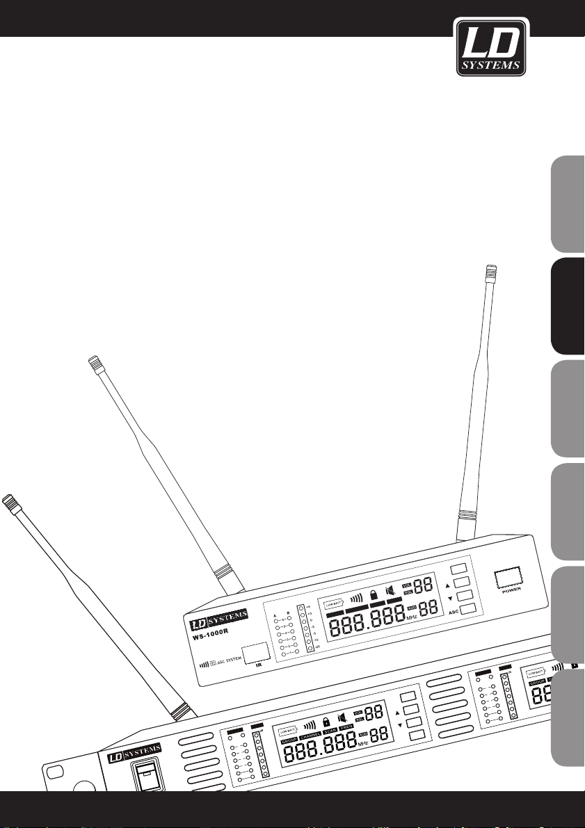
LD WS1000(2)(X)
160 CHN UHF PLL TRUE DIVERSITY WIRELESS SYSTEM
A A
B B
6
5
4
3
2
1
6
5
4
3
2
1
-5 -5
-3 -3
0 0
+3
+3
+6
+6
AF AF
R F RF
V
V
SE T
IR
GR
OU P CH A
NN
EL
SC AN
FR EQ
GR
OU
P C HAN NEL SC AN
FR
EQ
POWER
-20
-20
-10 -10
AS C
USER´S MANUAL
BEDIENUNGSANLEITUNG
MANUEL D`UTILISATION
MANUAL DE USUARIO
INSTRUKCJA OBSŁUGI
MANUALE D‘USO
Page 2

2
Thank you for choosing LD-Systems!
We have designed this product to operate reliably over many years. Therefore LD-Systems guarantees for high
quality products with its name and many years of experience as a producer.
Please, take a few moments to read these instructions carefully, as we want you to enjoy your new LD-Systems
products quickly and to the fullest.
For information about LD-Systems check out our website WWW.LD-SYSTEMS.COM
FRANCAISFRANCAIS FRANCAISFRANCAIS
ENGLISHDEUTSCHFRANCAIS
ESPAÑOLITALIANOPOLSKI
Page 3
LD WS1000(2)(X)
16 CHN UHF PLL TRUE DIVERSITY WIRELESS SYSTEM
790.850 - 813.800 MHz
838.850 - 864.900 MHz (X-Version)
A A
B B
6
5
4
3
2
1
6
5
4
3
2
1
-5 -5
-3 -3
0 0
+3
+3
+6
+6
AF
AF
R F RF
V
V
SE T
IR
GR OUP CH ANNE L S CA N
FR EQ
GR OUP C
HA
NNE L S CA N
POWE
R
-2
0 -20
-10
-10
AS C
3
ENGLISHDEUTSCHFRANCAIS
FRANCAISFRANCAIS FRANCAISFRANCAIS
ESPAÑOLITALIANOPOLSKI
Page 4
04
4
PREVENTIVE MEASURES:
1. Please read the attached safety instructions as well as the following instructions carefully.
2. Please keep all the instructions.
3. Please use the device only as intended.
4. Please respect the valid waste management rules. Please deliver the packaging divided into plastic and
paper/ cardboard to the recycling management.
5. Please refer all servicing to qualified personel only if the device is damaged, exposed to liquid/rain or if it does
not operate normally.
6. Please, do not expose to any kind of heat such as ovens, radiators, or any other devices (incl. amplifiers).
Please check for enough distance between amplifiers and walls, racks, etc. to prevent overheating.
7. After connection please check the wiring to prevent any kind of accident or damage.
Please never use any kind of damaged cable and wiring.
8. Only use authorized and stable stands, brackets, shelfs, tables etc.. for installations. Please check for
adequate stability against collapse.
9. Please check operating voltage before connecting. Wrong voltage will damage your device.
CAUTION:
To reduce the risk of electric shock, do not remove cover (or back). No user serviceable parts inside. Refer
servicing to qualified personnel.
The lightning flash with arrowhead symbol within an equilateral triangle is intended to alert the
user to the presence of uninsulated “dangerous voltage” within the product´s enclosure that may be
of sufficient magnitude to constitute a risk to persons.
The exclamation mark within an equilateral triangle is intended to alert the user to the presence of
important operating and maintenance (servicing) instructions in the literature accompanying the
appliance.
CAUTION! HIGH VOLUME!
You will operate this system for professional use. Therefore the commercial use of this equipment is liable to the
rules and regulations of the Accident Prevention & Insurance Association of your industry sector. Adam Hall as a
manufacturer is bound to inform you formally about the existence of eventual sanitary risks.
These speakers are able to induce high acoustic sound pressure levels. 85 db is by law the maximum audio
pressure level which your ear can be exposed to during a work day. It was set according to the technical expertise of the occupational medicine as a basis for the noise rating level. Higher sound levels or longer exposition
times could damage your ear. The time of exposition by higher sound pressure levels should be shortened in
order to prevent from ear damages. Here are a few reliable warning signals which show that you have exposed
yourself for a too long period to excessive sound pressure levels:
- You hear bell- or whistling sounds!
- You have the impression that you can’t hear high tones anymore!
CA UT IO N
RISK OF EL ECT RIC SHOC K
DO N OT OP EN
FRANCAISFRANCAIS FRANCAISFRANCAIS
ENGLISHDEUTSCHFRANCAIS
ESPAÑOLITALIANOPOLSKI
Page 5
INTRODUCTION:
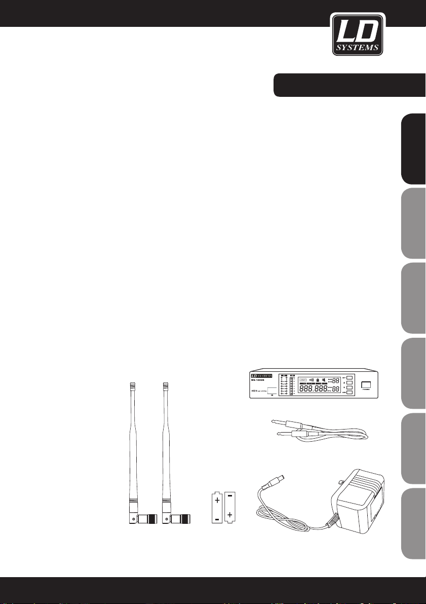
INCLUDED IN ALL
SYSTEMS:
Receiver (X)
2 AA batteries
6.3 mm jack plug cable
Power supply
Two antennas
User's manual
The WS-1000 system offers an excellent solution for users who want an advanced UHF system. With its 160
frequency bands, the WS-1000 is suitable for many applications, for example, live shows, broadcasts, meetings,
instruments, etc.
Touch buttons and LCD displays permit fast and simple setup. This manual will show you everything you need to
know in order to operate the system correctly and safely.
790.850 - 813.800 MHz
838.850 - 864.900 MHz (X-Version)
Most countries regulate the frequencies that may be used for wireless data transmission. These regulations
stipulate which devices may operate in which frequency range. This minimizes interference. To permit trouble
free operation of the system, two different frequency bands are offered. To avoid problems with RF interference,
the system is supplied with pre-set frequency groups.
If you use only one system, it should not be necessary to change the operating frequency.
If you use multiple devices at the same time, you should set each device to a different channel.
The group channel system offers optimal distribution among the frequencies when multiple systems are used
at the same time. With one frequency band, you can use up to 8 individual transmitter-receiver systems in an
installation at the same time.
5
ENGLISHDEUTSCHFRANCAIS
FRANCAISFRANCAIS FRANCAISFRANCAIS
ESPAÑOLITALIANOPOLSKI
Page 6

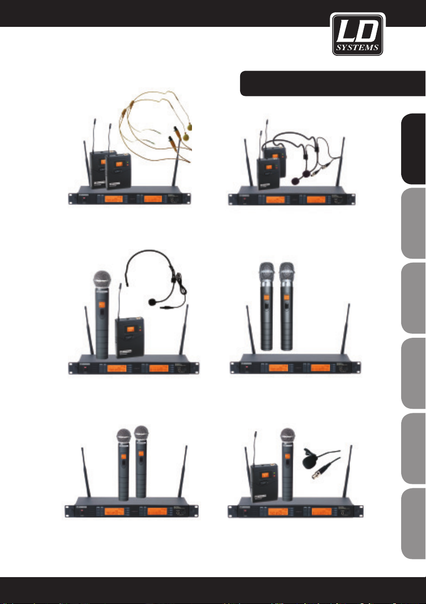
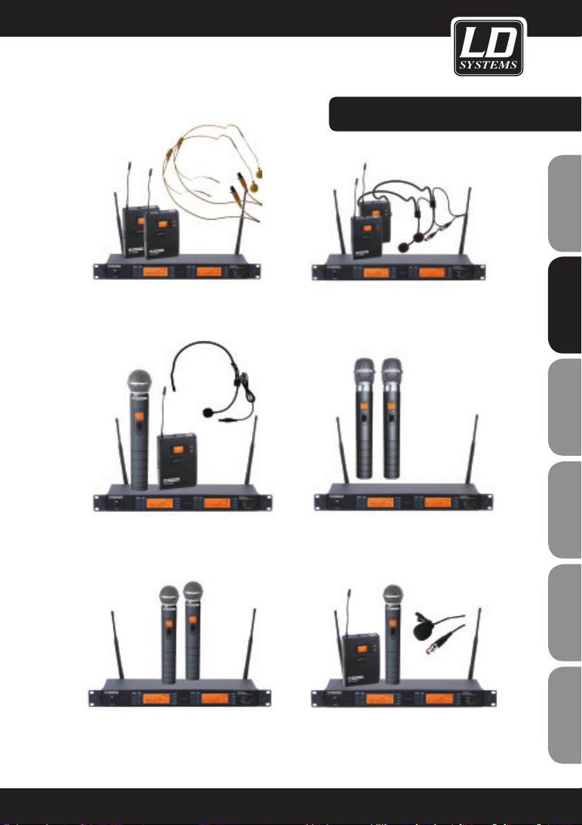
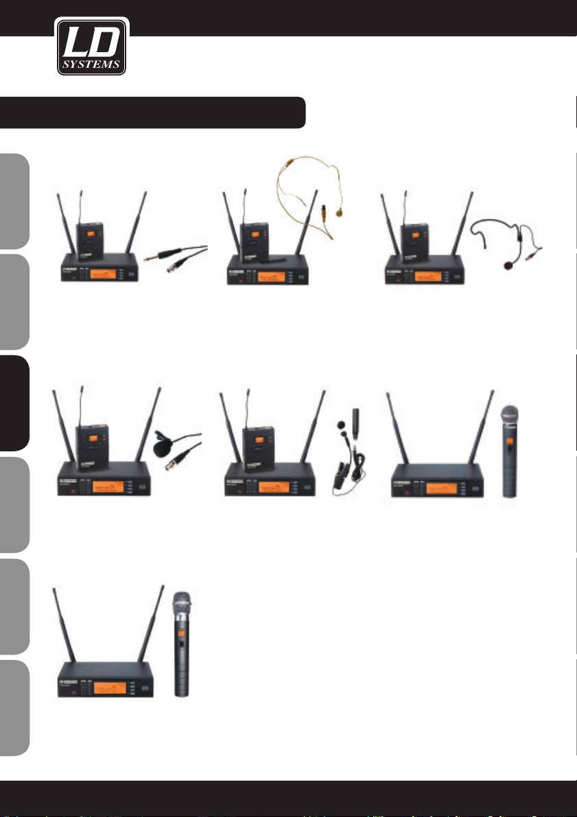
LD WS1000R PARTS:
LDWS1000BPG(X)
wireless microphone system with
belt pack and guitar cable
LDWS1000BPHH(X)
wireless microphone system
with 2 x belt pack and 2 x skin-
coloured headset
LDWS1000BPH(X)
wireless microphone system with
belt pack and headset
LDWS1000BPL(X)
wireless microphone system with
belt pack and lavaliere micro-
phone
LDWS1000HHD(X)
wireless microphone system with
handheld dynamic microphone
LDWS1000BPW(X)
wireless microphone system with
belt pack and brass instrument
microphone
LDWS1000HHC(X)
wireless microphone system with
handheld condenser microphone
6
FRANCAISFRANCAIS FRANCAISFRANCAIS
ENGLISHDEUTSCHFRANCAIS
ESPAÑOLITALIANOPOLSKI
Page 7
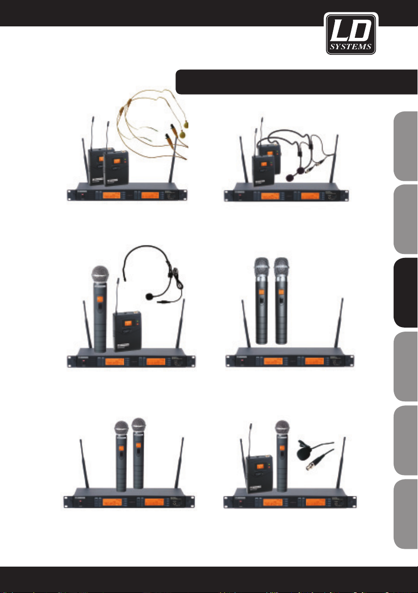
LD WS1000R2 PARTS:
LDWS1000BPHH2(X)
wireless microphone system with
2 x belt pack and 2 x skin-coloured
headset
LDWS1000HBH2(X)
wireless microphone system with
handheld dynamic microphone and
headset
LDWS1000HHD2(X)
wireless microphone system with
2 x handheld dynamic microphone
and headset
LDWS1000HHC2(X)
wireless microphone system with 2
x handheld condenser microphone
and headset
LDWS1000BPH2(X)
wireless microphone system with 2 x
belt pack and 2 x headset
LDWS1000HHL2(X)
wireless microphone system with hand-
held dynamic microphone and lavaliere
microphone
7
ENGLISHDEUTSCHFRANCAIS
FRANCAISFRANCAIS FRANCAISFRANCAIS
ESPAÑOLITALIANOPOLSKI
Page 8
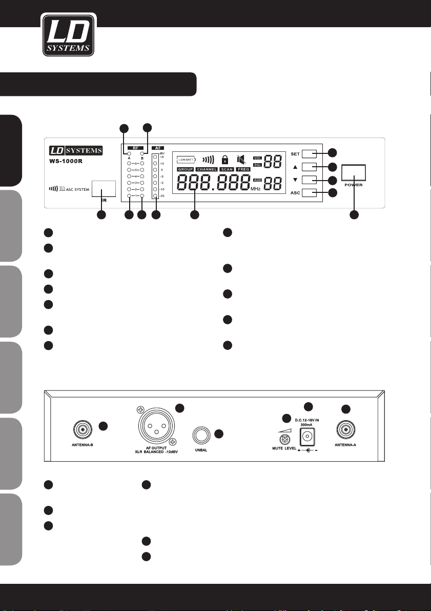
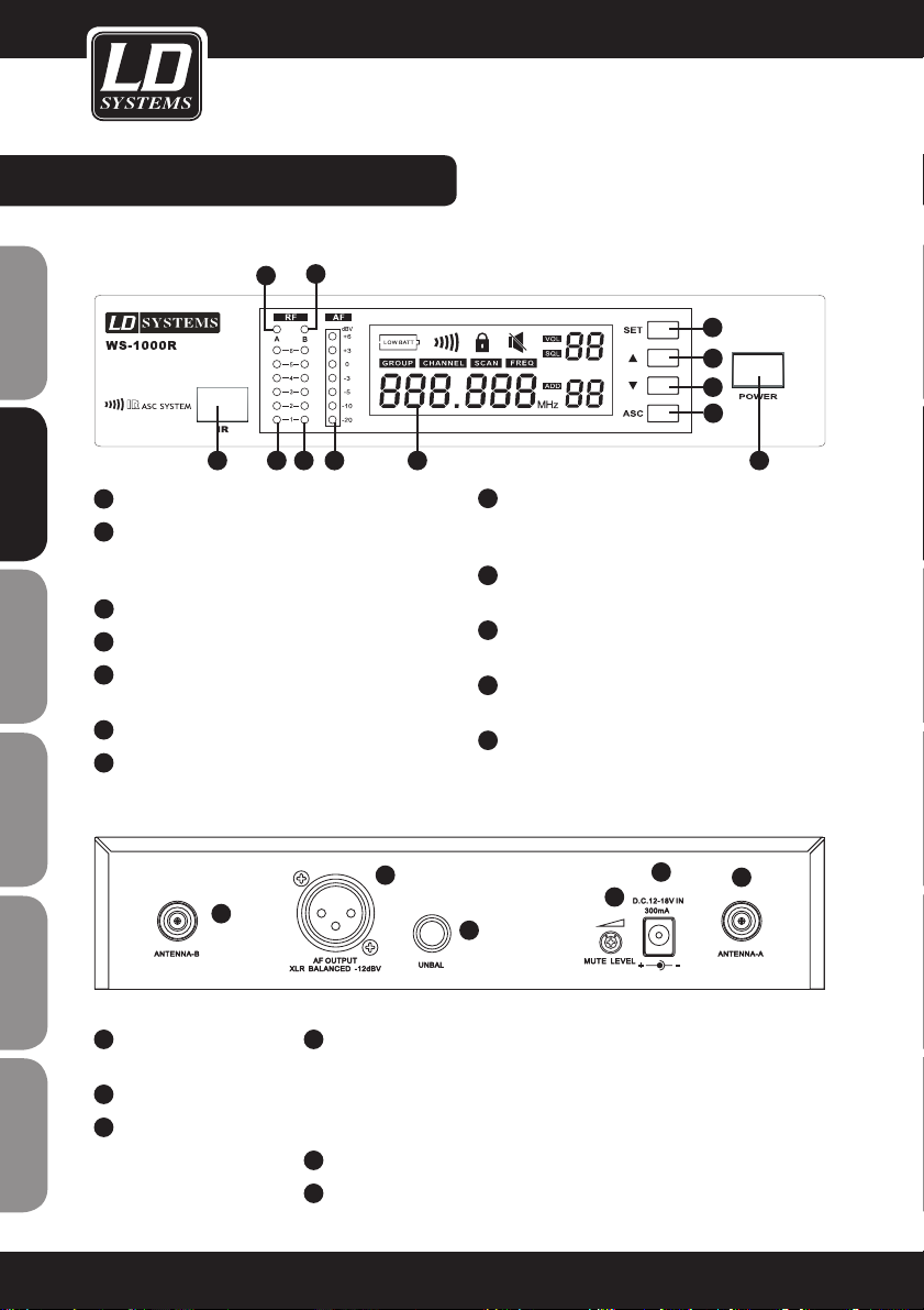
LD WS1000R RECEIVER:
FRONT PANEL:
BACK PANEL
1
INFRARED (IR) WINDOW
2
ANTENNA A RECEIVER INDICATOR
Indicator lights up to signal that Receiver A is on.
3
ANTENNA A SIGNAL STRENGTH INDICATOR
4
ANTENNA B SIGNAL STRENGTH INDICATOR
5
ANTENNA B RECEIVER INDICATOR
Indicator lights up to signal that Antenna B is on.
6
CHANNEL AUDIO INDICATOR
7
CHANNEL LCD INDICATOR
Please refer to the system settings.
1
ANTENNA CONNECTOR B
50 Ω
2
XLR OUTPUT SOCKET
3
6.3 MM OUTPUT SOCKET
8
SYNC BUTTON (ASC)
Press here to establish an infrared link
between transmitter and receiver.
9
DOWN ARROW BUTTON
Use this button to navigate the menu.
10
UP ARROW BUTTON
Use this button to navigate the menu.
11
SYSTEM SETTINGS BUTTON
Please refer to the system settings.
12
ON/OFF SWITCH
4
FINE ADJUSTMENT OF THE MUTE THRESHOLD VALUE
Fine adjustment of the mute threshold value. Generally, it should not be
necessary to change this value. It is set correctly at the factory. If, however,
you receive interference, then you can increase this threshold value by
turning the control to the right until the RF signal LED goes out.
5
AC ADAPTER CONNECTOR
6
ANTENNA CONNECTOR A 50 Ω
1
2
3 456 7
8
9
10
12
11
1
2
3
4
5
6
8
FRANCAISFRANCAIS FRANCAISFRANCAIS
ENGLISHDEUTSCHFRANCAIS
ESPAÑOLITALIANOPOLSKI
Page 9
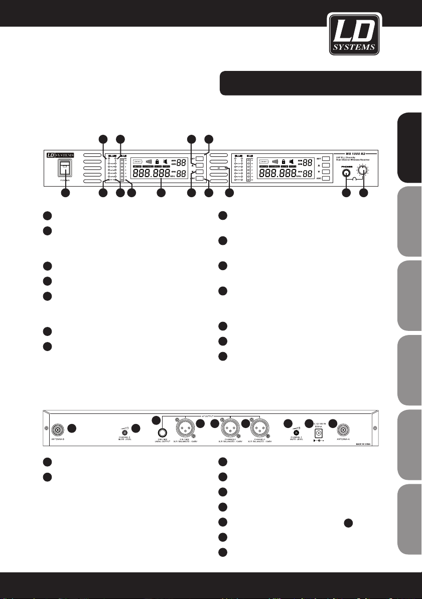
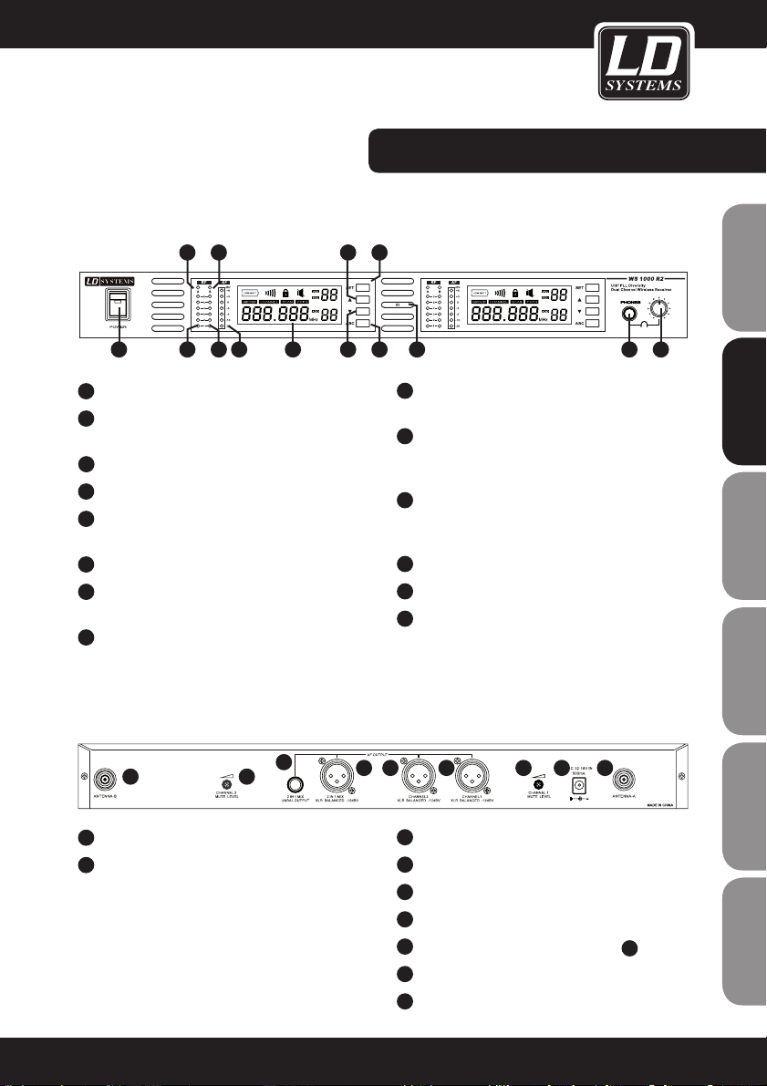
LD WS1000R2 RECEIVER:
FRONT PANEL:
BACK PANEL
1
ON/OFF SWITCH
2
ANTENNA A RECEIVER INDICATOR
Indicator lights up to signal that Antenna A is
receiving.
3
ANTENNA A RF INDICATOR
4
ANTENNA B RF INDICATOR
5
ANTENNA B RECEIVER INDICATOR
Indicator lights up to signal that Antenna B is
receiving.
6
CHANNEL 1 AUDIO AF LEVEL INDICATOR
7
CHANNEL / GROUP 1 LCD INDICATOR
Please refer to the system setup.
1
ANTENNA CONNECTOR B
2
MUTE THRESHOLD CHANNEL 2
Fine adjustment of the mute threshold value for
channel 2. Generally, it should not be necessary to
change this value. It is set correctly at the factory.
If, however, you receive interference, then you can
increase this threshold value, when the
transmitters are off, by turning the control to the
right until the RF signal LED goes out.
8
UP ARROW BUTTON
Use this button to navigate the menu.
9
SYSTEM SETUP BUTTON
Please refer to the system setup.
10
DOWN ARROW BUTTON
Use this button to navigate the menu.
11
SYNC BUTTON (ASC)
Press here to establish an infrared link
between receiver and transmitter.
12
INFRARED (IR) WINDOW
13
6.3 MM JACK HEADPHONE CONNECTION
14
HEADPHONE VOLUME
3
6.3 MM JACK OUTPUT SOCKET FOR MIX
4
XLR OUTPUT SOCKET FOR MIX
5
CHANNEL 2 XLR OUTPUT SOCKET
6
CHANNEL 1 XLR OUTPUT SOCKET
7
MUTE THRESHOLD CHANNEL 1 (SEE
2)
8
AC POWER ADAPTER
9
ANTENNA CONNECTOR A
1 2
3
4 5 6 7 8 9
2315
4
8
1076
9
11
141312
9
ENGLISHDEUTSCHFRANCAIS
FRANCAISFRANCAIS FRANCAISFRANCAIS
ESPAÑOLITALIANOPOLSKI
Page 10

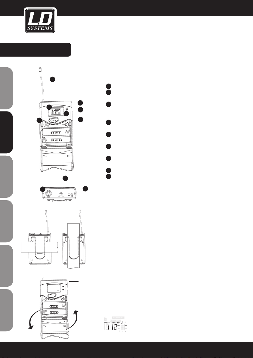
BELT PACK:
1
Antenna
2
LCD display
Please refer to "System Setup" on page 7.
3
Power/ASC indicator
Continuous green: in operation
Green flashing: IR transmission in progress
4
Mute indicator
Red indicates mute mode
5
Power/mute switch
Press for 3 seconds to switch on or off
6
IR window
For receiving synchronization frequencies via infrared link.
7
Select button
Please refer to the system settings.
8
3-pin microphone input
9
The body pack has three possible gain settings
Select the appropriate setting for your instrument
Mic: microphone
0: guitar with passive pickups
-10dB: guitar with active pickups
WEARING THE BELT PACK TRANSMITTER
Fasten the transmitter to a belt or a guitar strap.
The most secure way to fasten the transmitter is to press it down
all the way so that the belt or strap is enclosed by the clip, as in the
first variant.
CHANGING BATTERIES
As a rule, 2 alkaline batteries will last for up to 8 hours. When the
LED for the battery status indicator flashes, you should change the
batteries immediately.
Flashes!
1
2
3
4
5
7
6
9
1
8
Flashes
green
10
FRANCAISFRANCAIS FRANCAISFRANCAIS
ENGLISHDEUTSCHFRANCAIS
ESPAÑOLITALIANOPOLSKI
Page 11

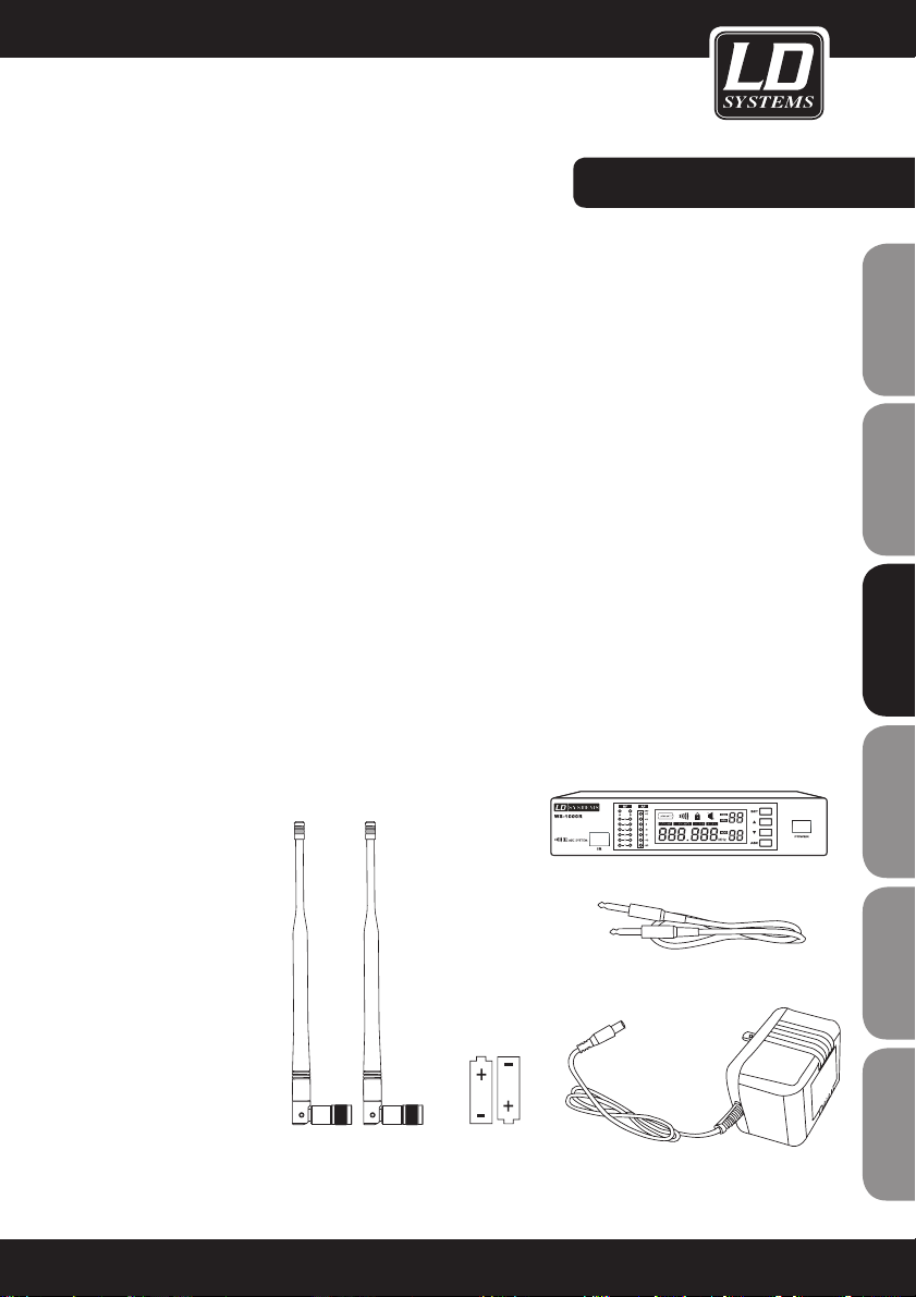
HANDHELD TRANSMITTER:
PROGRAMMING THE TRANSMITTER:
1
Dynamic microphone (WS-1000MD)
2
Condenser microphone (WS-1000MC)
3
LCD display
4
On/off switch
5
Adjustment for the sensitivity of the microphone
(turn left for lower, turn right for higher sensitivity)
Please refer to the system settings.
Handheld transmitter functions:
6
Receives infrared signals to synchronize transmitter and
receiver.
CHANGING BATTERIES:
As a rule, 2 alkaline batteries will last for up to 14 hours. When the
battery status indicator flashes, you should change the batteries
immediately.
1
2
3
4
5
6
Flashes!
MD MC
11
ENGLISHDEUTSCHFRANCAIS
FRANCAISFRANCAIS FRANCAISFRANCAIS
ESPAÑOLITALIANOPOLSKI
Page 12
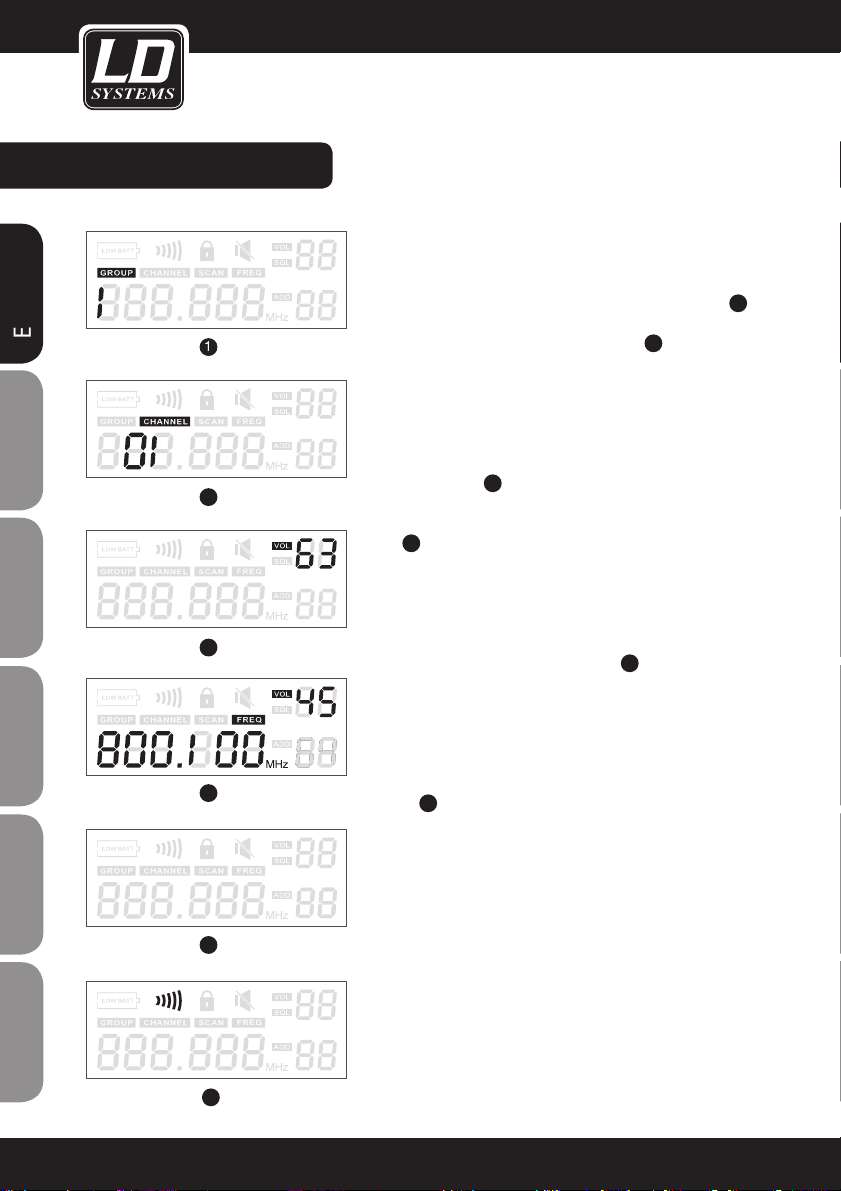
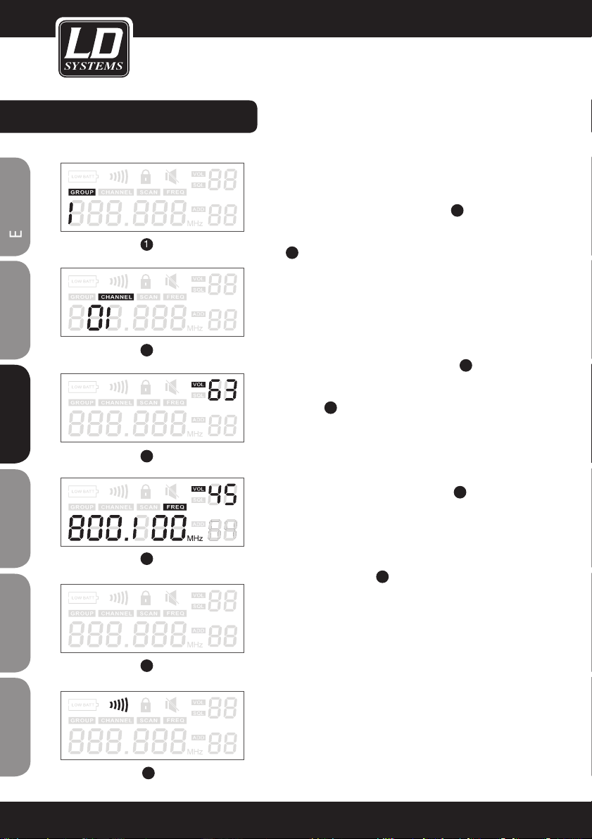
SYSTEM SETTINGS:
PROGRAMMING THE RECEIVER:
Selecting the group and the channel: Press "SET" until "GROUP" appears, then press the arrow buttons to select a frequency group 1.
Now press "SET" again until "CHANNEL" is displayed, then use
the arrow buttons to select the desired channel
2
.
To obtain the best results with multiple systems, assign all devices
to the same group and set a different frequency in each device.
Receiver volume: If nothing else is selected on the display, you can
regulate the volume of the system using the arrow buttons. The
volume is adjustable in 64 increments. We recommend a volume
between 42 and 45 3.
Normal display: RF level, group no.,channel no., frequency as
usual
4
.
Infrared frequency search: Please note: When multiple systems are
used, the respective addresses of the individual systems must be
different. Switch off the transmitter and open the battery compartment (only for body pack - in handheld systems, the IR interface is
on the bottom, in this connection, see point 6 on the preceding page of this manual). Position the transmitter and receiver
opposite one another so that the IR interfaces of both devices are
as close to one another as possible. Press the "ASC" button and
switch on the transmitter again. Now also press the "ASC" button
on the transmitter. Whenever you press the ASC button, the IR
indicator lights up and the receiver sends sync frequencies for 25
seconds
6.
The handheld transmitter lights up when these synch frequencies
are received; with the body pack, the entire display illumination
flashes and the IR symbol is also active.
Important: During this procedure, the distance between the two
devices should be less than 0.5 metres. You cannot synchronize
more than one transmitter simultaneously using this procedure.
Auto scan function: The WS1000 series has a frequency auto scan
function. This function helps to find frequencies that are free of
interference within a group. Press "SET" 3 times until "SCAN"
appears in the display. Press one of the arrow buttons to start the
frequency scan.
2
1
2
3
4
5
6
12
FRANCAISFRANCAIS FRANCAISFRANCAIS
ENGLISHDEUTSCHFRANCAIS
ESPAÑOLITALIANOPOLSKI
Page 13
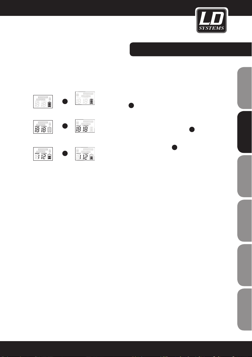
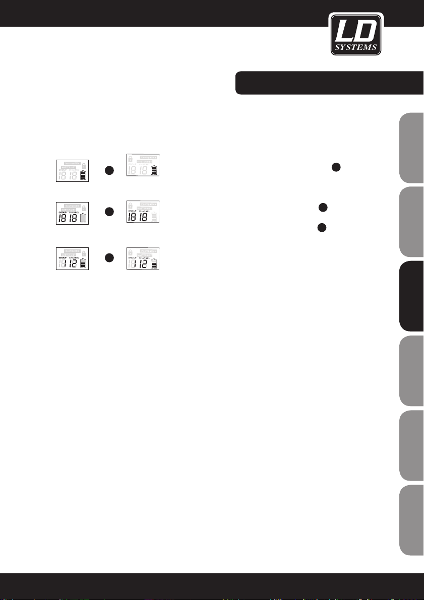
SYSTEM SETTINGS:
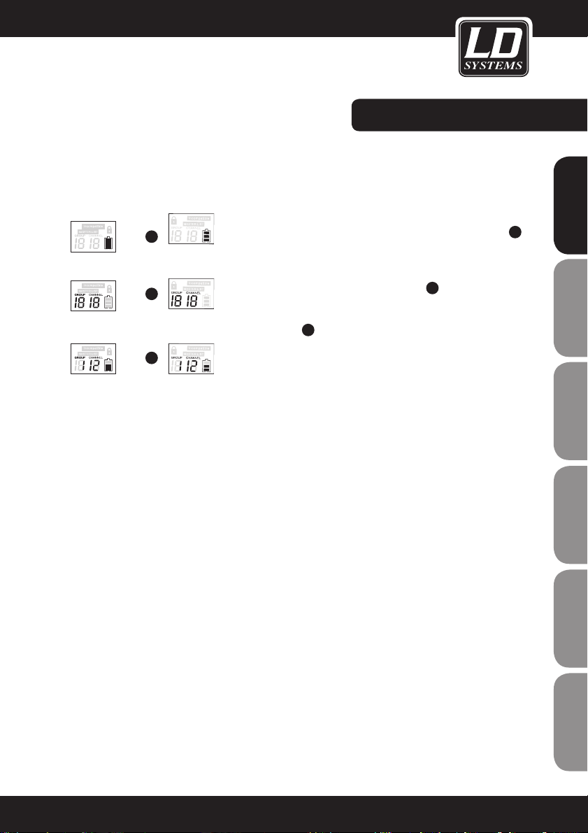
Battery status: Both handheld transmitter and body pack indicate
the battery status on the display (see the following illustration 1)
Group and channel display: Once the link between both devices
is established, the display on both devices continues to show the
group and channel for another 5 seconds 2. Then the display
returns to the normal status, in which the battery status and
working frequency are shown (in this connection, see the following
illustration 3).
1
2
3
Handheld
transmitter
Body pack
transmitter
13
ENGLISHDEUTSCHFRANCAIS
FRANCAISFRANCAIS FRANCAISFRANCAIS
ESPAÑOLITALIANOPOLSKI
Page 14

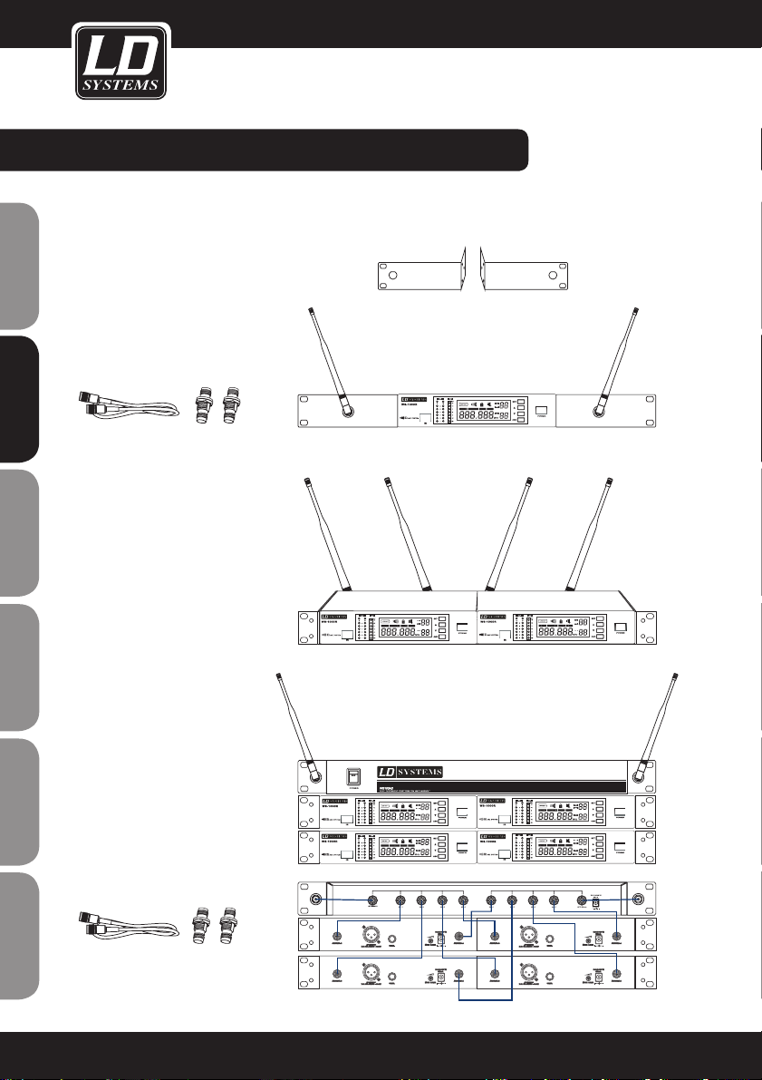
RACK INSTALLATION OF THE RECEIVER:
One receiver
(with WS100RK rack kit, optional)
Rack kit WS100RK with 2 rack
mount adapters, 2 TNC connection cables and 2 TNC adapter
connectors
Two receivers
(with WS100RK rack kit, optional)
Four receivers
With WS100RK2 (optional) Rack Kit
and WS100AD Antenna Split Box
(optional)
Ten TNC connection cables
(included)
Two TNC connectors (included)
19“ rack wings
14
FRANCAISFRANCAIS FRANCAISFRANCAIS
ENGLISHDEUTSCHFRANCAIS
ESPAÑOLITALIANOPOLSKI
Page 15
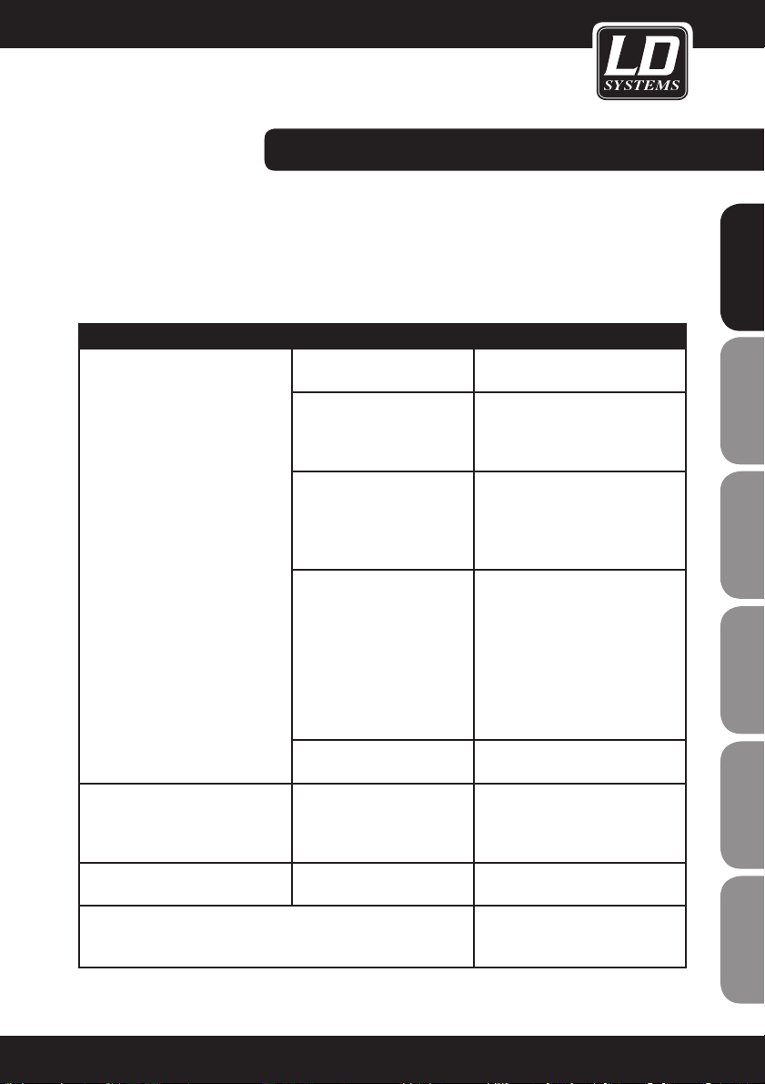
TIPS FOR IMPROVING PERFORMANCE:
Aim the transmitter directly at the receiver ("line-of-sight" contact between the devices). Do not position the
receiver near metal objects/surfaces or digital devices (CD players, computers, etc.).
Position the receiver so that it is not directly in front of a wall and is at least 1 m above the floor. Cell phones, bidirectional radio devices, etc. can interfere with the radio link between transmitter and receiver and should not be
operated in the vicinity of the transmitter.
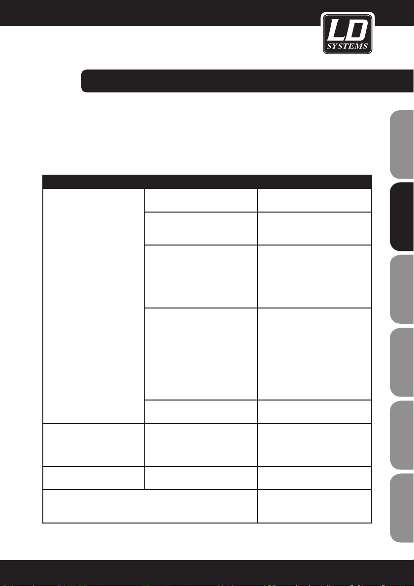
PROBLEM DISPLAY SOLUTION
No sound or volume too low Transmitter: on/off indicator
is off
Make certain that the unit is connected correctly.
"Power" indicator is off Make certain that the AC adapter is
plugged into the device correctly and
the other end is plugged in correctly
on the back.
Receiver: RF indicator is on
Increase the volume. Increase the
gain setting on the transmitter.
Check the power connections of the
receiver and the connected amplifier
and/or mixer.
Receiver: RF indicator is off.
Transmitter: indicator is on
Do not position the receiver near
metal objects. Check whether the
transmission path between transmitter and receiver is unobstructed
("line-of-sight" contact).
Position the transmitter closer to
the receiver. Make certain that the
transmitter and the receiver are
using the same frequency
Transmitter: battery status
indicator is on
Replace the batteries
Distortion or unwanted noise Receiver: RF indicator is on
Remove possible sources of
interference (CD players, computers,
digital effects units, in-ear monitoring systems, etc.)
Increasing distortion Transmitter: battery status
indicator is on
Replace the batteries
Substantial difference in levels in comparison with wired operation with
the same source or when other guitars or microphones are used
Adjust the gain setting on the
transmitter and the volume on the
receiver accordingly.
15
ENGLISHDEUTSCHFRANCAIS
FRANCAISFRANCAIS FRANCAISFRANCAIS
ESPAÑOLITALIANOPOLSKI
Page 16
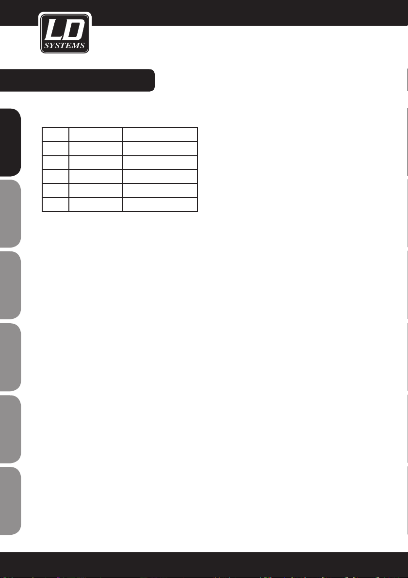
SPECIFICATIONS:
SYSTEM
Frequency range and transmitter RF level
Band Range Transmitter RF level
UA 518-548 MHz 13dBm
UB 630-660 MHz 13dBm
UC 740-770 MHz 10dBm
UD 800-822 MHz 10dBm
UE 838-865 MHz 10dBm
Range under typical conditions:
80 m
(Range depends on absorption and reflection of
and interference with the RF signal)
Audio transmission range:
60 – 16,000 Hz
Harmonic distortion at 1 kHz:
<1%
Dynamic range:
>90 dB (A-weighted)
Operating temperature:
-10°C to +50°C
(Battery characteristics may limit this range)
BELT PACK TRANSMITTER
Maximum audio input level:
0 dBV max. in mic gain position
+10 dBV max. in 0 dB gain position
+20 dBV max. in -10 dB gain position
Gain adjustment range:
30 dB
Input impedance:
470 kΩ
Dimensions (W x H x D):
89 x 65 x 24 mm
Weight:
85 g without batteries
Operation:
With 2x Type AA alkaline batteries or 2x Type AA
rechargeable batteries
Operating time:
up to 13 hours with alkaline batteries
HANDHELD TRANSMITTER
Dimensions with microphone capsule:
243 mm long, 50 mm diameter
Weight:
300 g
Operation:
with 2 x Type AA alkaline batteries or 2 x Type
AA rechargeable batteries
Operating time:
up to 14 hours with alkaline batteries
RECEIVER
Audio output level:
XLR balanced: - 12 dBV
6.3 mm jack: - 18 dBV
Output impedance:
XLR: 200 ohms
Jack: 1 kohm
XLR pinout:
Pin 1: ground
Pin 2: (+)
Pin 3: (-)
Dimensions (W x H x D):
44 x 212 x 160 mm
Weight:
900 g
Power supply:
LDWS1000: 12 – 18 V DC, 500 mA (powered
by external AC adapter)
LDWS1000 dual receiver: 12 – 18 V DC, 1000
mA (powered by external AC adapter)
Our products are subject to a continuous process of development and improvement. Thus
technical characteristics are subject to change
without notice.
16
FRANCAISFRANCAIS FRANCAISFRANCAIS
ENGLISHDEUTSCHFRANCAIS
ESPAÑOLITALIANOPOLSKI
Page 17

17
ENGLISHDEUTSCHFRANCAIS
FRANCAISFRANCAIS FRANCAISFRANCAIS
ESPAÑOLITALIANOPOLSKI
Page 18

18
MANUFACTURER´S DECLARATIONS:
LIMITED WARRANTY
This Limited Warranty applies to the Adam Hall, LD Systems, Defender, Palmer and Eminence branded products.
The statutory warranty rights towards the seller are not affected by this guarantee. In fact, it justifies, additional
independent warranty claims towards Adam Hall.
Adam Hall warrants that the Adam Hall product you have purchased from Adam Hall or from an Adam Hall authorized reseller is free from defects in materials or workmanship under normal use for a period of 2 or 5 years from
the date of purchase.
The Limited Warranty Period starts on the date of purchase. In order to receive warranty services you are required
to provide proof of the purchase date. Your dated sales or delivery receipt, showing the date of purchase, is your
proof of the purchase date. Should products of the brands named above be in need of repair within the limited warranty period, you are entitled to warranty services according to the terms and conditions stated in this document.
This Limited Warranty extends only to the original purchaser of this Adam Hall branded product and is not transferable to anyone who obtains ownership of the Adam Hall branded product from the original purchaser. During the
Limited Warranty Period, Adam Hall will repair or replace the defective component parts or the product. All component parts or hardware products removed under this Limited Warranty become the property of Adam Hall.
In the unlikely event that your Adam Hall product has a recurring failure, Adam Hall, at its discretion, may elect to
provide you with a replacement unit of Adam Hall´s choice that is at least equivalent to your Adam Hall branded
product in hardware performance.
Adam Hall does not warrant that the operation of this product will be uninterrupted or error-free. Adam Hall is not
responsible for damage that occurs as a result of your failure to follow the instructions included with the Adam
Hall branded product.
This Limited Warranty does not apply:
- to wear parts (e.g. accumulator)
- to any product from which the serial number has been removed or that has been damaged or rendered defec
tive as the result of an accident
- in case of, misuse, abuse, or other external causes
- by operation outside the usage parameters stated in the user´s documentation shipped with the product
- by use of spare parts not manufactured or sold by Adam Hall
- by modification or service by anyone other than Adam Hall
These terms and conditions constitute the complete and exclusive warranty agreement between you and Adam
Hall regarding the Adam Hall branded product you have purchased.
FRANCAISFRANCAIS FRANCAISFRANCAIS
ENGLISHDEUTSCHFRANCAIS
ESPAÑOLITALIANOPOLSKI
Page 19
19
MANUFACTURER´S DECLARATIONS:
LIMITATION OF LIABILITY
If your Adam Hall branded hardware product fails to work as warranted above, your sole and exclusive remedy
shall be repair or replacement. Adam Halls’ maximum liability under this limited warranty is expressly limited
to the lesser of the price you have paid for the product or the cost of repair or replacement of any hardware
components that malfunction in conditions of normal use.
Adam Hall is not liable for any damages caused by the product or the failure of the product, including any lost
profits or savings or special, incidental, or consequential damages. Adam Hall is not liable for any claim made by
a third party or made by you for a third party.
This limitation of liability applies whether damages are sought, or claims are made, under this Limited Warranty
or as a tort claim (including negligence and strict product liability), a contract claim, or any other claim. This limitation of liability cannot be waived or amended by any person. This limitation of liability will be effective even if
you have advised Adam Hall of an authorized representative of Adam Hall of the possibility of any such damages.
This limitation of liability however, will not apply to claims for personal injury.
This Limited Warranty gives you specific legal rights. You may also have other rights that may vary from state to
state or from country to country. You are advised to consult applicable state or country laws for a full determination of your rights.
REQUESTING WARRANTY-SERVICE
To request warranty service for the product, contact Adam Hall or the Adam Hall authorized reseller from which
you purchased the product.
EC DECLARATION OF CONFORMITY
These devices meet the essential requirements and further relevant specifications of Directives 1999/5/EC (R &
TTE), 2004/108/EC (EMC) and 2006/95/EC (LVD). For more information, see www.adamhall.com.
CORRECT DISPOSAL OF THIS PRODUCT (ELECTRICAL WASTE)
(Applicable in the European Union and other European countries with separate collection systems)
This marking shown on the product or its literature, indicates that it should not be disposed with other household
wastes at the end of its working life. To prevent possible harm to the environment or human health from uncontrolled waste disposal, please separate this from other types of wastes and recycle it responsibly to promote the
sustainable reuse of material resources.
Household users should contact either the retailer where they purchased this product, or their local government
office, for details on where and how they can recycle this item in an enviromentally friendly manner.
Business users should contact their supplier and check the terms and conditions of the purchase contract. This
product should not be mixed with other commercial wastes for disposal.
ENGLISHDEUTSCHFRANCAIS
FRANCAISFRANCAIS FRANCAISFRANCAIS
ESPAÑOLITALIANOPOLSKI
Page 20
20
WEEE-DECLARATION
Your LD-Systems product was developed and manufactured with high quality materials and components wich
can be recycled and/or reused. This symbol indicates that electrical and electronic equipment must be disposed
of separately from normal waste at the end of its operational lifetime.
Please dispose of this product by bringing it to your local collection point or recycling centre for such equipment.
This will help to protect the environment in which we all live.
BATTERIES AND ACCUMULATORS
The supplied batteries or rechargeable batteries can be recycled. Please dispose of them as special waste or return
them to your specialist dealer. In order to protect the environment, only dispose exhausted batteries.
Adam Hall GmbH, all rights reserved. The technical data and the functional product characteristics can be subject
to modifications. The photocopying, the translation, and all other forms of copying of fragments or of the integrality of this user’s manual is prohibited.
MANUFACTURER´S DECLARATIONS:
FRANCAISFRANCAIS FRANCAISFRANCAIS
ENGLISHDEUTSCHFRANCAIS
ESPAÑOLITALIANOPOLSKI
Page 21

21
ENGLISHDEUTSCHFRANCAIS
FRANCAISFRANCAIS FRANCAISFRANCAIS
ESPAÑOLITALIANOPOLSKI
Page 22

22
Mit einem Produkt von LD Systems haben Sie die richtige Wahl getroffen!
Dieses Gerät wurde unter hohen Qualitätsanforderungen entwickelt und gefertigt, um viele Jahre einen reibungslosen Betrieb zu gewährleisten. Dafür steht LD Systems mit seinem Namen und der langjährigen Erfahrung als
Hersteller hochwertiger Audioprodukte.
Bitte lesen Sie diese Bedienungsanleitung sorgfältig, damit Sie Ihr neues Wireless System von LD Systems
schnell optimal einsetzen können.
Weitere Informationen zu Produkten von LD Systems erhalten Sie auf unserer Internet-Seite WWW.LD-SYSTEMS.COM.
FRANCAISFRANCAIS FRANCAISFRANCAIS
ENGLISHDEUTSCHFRANCAIS
ESPAÑOLITALIANOPOLSKI
Page 23
LD WS1000(2)(X)
16 CHN UHF PLL TRUE DIVERSITY WIRELESS SYSTEM
790.850 - 813.800 MHz
838.850 - 864.900 MHz (X-Version)
A A
B
B
6
5
4
3
2
1
6
5
4
3
2
1
-5 -5
-3 -3
0 0
+3
+3
+6
+6
AF
AF
R F
R F
V
V
SE T
IR
GR
OU P CH ANNE L S CA N
FR EQ
GR OUP CH ANNE L S CA N
POWER
-2
0 -20
-1
0 -1
0
AS C
23
ENGLISHDEUTSCHFRANCAIS
FRANCAISFRANCAIS FRANCAISFRANCAIS
ESPAÑOLITALIANOPOLSKI
Page 24
04
24
1. Bitte beachten Sie die Sicherheitshinweise und studieren Sie diese Anleitung sorgfältig.
2. Bewahren Sie alle Hinweise und Anleitungen sicher auf.
3. Verwenden Sie das Gerät nur in der vorgesehenen Art und Weise.
4. Beachten die in Ihrem Land geltenden Entsorgungsgesetze. Trennen Sie bei der Entsorgung bitte Plastik und
Papier bzw. Kartonagen von einander.
5. Sollte Ihr Gerät nicht mehr ordnungsgemäß funktionieren, Flüssigkeiten ausgesetzt werden oder auf sonstige Art
und Weise beschädigt sein, überlassen Sie bitte jegliche Reparaturen ausschließlich autorisiertem Fachpersonal.
6. Halten Sie das Gerät von Hitzequellen wie z.B. Ofen, Heizkörper, oder sonstige Quellen (auch Verstärker) fern.
Sorgen Sie dafür dass das Gerät immer so installiert ist, dass es ausreichend gekühlt wird und nicht überhitzt.
7. Überprüfen Sie alle Verbindungen nach dem Sie das Gerät angeschossen haben um Schäden oder Unfälle zu
vermeiden.
8. Verwenden Sie ausschließlich stabile und passende Stative bzw. Befestigungen wenn das Gerät fest installiert
wird. Stellen Sie sicher, dass das Gerät sicher installiert ist und nicht herunterfallen kann.
9. Auftretende Störungen beim Betrieb von Wireless Systemen.
Beim gleichzeitigen Betrieb von Funkmikrofonen und Funktelefonen (bei geringer Entfernung der Geräte zu
einander) können im Bereich der Funkmikrofone Störungen auftreten, welche im angeschlossenen
Audiosystem hörbar sind.
ACHTUNG:
Entfernen Sie niemals die Abdeckung, da sonst die Gefahr eines elektrischen Schocks besteht.
Im Inneren des Gerätes befinden sich keine Teile, die vom Bediener gewartet oder repariert werden können.
Lassen Sie Reparaturen ausschließlich von qualifiziertem Servicepersonal durchführen.
Dieses Symbol warnt vor nichtisolierten, gefährlichen Spannungen im Geräteinneren,
die einen gefährlichen Schlag verursachen können.
Dieses Symbol kennzeichnet wichtige Bedienungs- und Wartungshinweise.
Vorsicht! Hohe Lautstärke!
Diese Übertragungsanlage wird von Ihnen professionell eingesetzt. Daher unterliegt der Gebrauch bei gewerblicher Nutzung den Regeln und Vorschriften der zuständigen Berufsgenossenschaft. Adam Hall als Hersteller ist
daher verpflichtet, Sie auf möglicherweise bestehende gesundheitliche Risiken ausdrücklich hinzuweisen.
Mit diesem System können Schalldrücke über 80 db erzeugt werden. 85db ist der Schalldruck, der laut Gesetz
als maximal zulässiger Wert über die Dauer eines Arbeitstages auf Ihr Gehör einwirken darf. Er wird nach den
Erkenntnissen der Arbeitsmedizin als Berurteilungspegel zu Grunde gelegt. Höhere Lautstärken oder längere
Einwirkzeit können Ihr Gehör schädigen. Bei höheren Lautstärken muss die Hörzeit verkürzt werden, um eine
Schädigung auszuschließen. Sichere Warnsignale dafür, dass Sie sich zu lange zu lautem Geräusch ausgesetzt
haben, sind:
- Sie hören Klingel- oder Pfeifgeräusche in den Ohren!
- Sie haben den Eindruck, hohe Töne nicht mehr wahrzunehmen!
VORSICHTSMASSNAHMEN:
CAU TI ON
RIS KO FE LECT RIC S HOC K
DON OT O PEN
FRANCAISFRANCAIS FRANCAISFRANCAIS
ENGLISHDEUTSCHFRANCAIS
ESPAÑOLITALIANOPOLSKI
Page 25

EINLEITUNG:
IN ALLEN SYSTEMEN
ENTHALTEN:
Empfänger (X)
2 AA Batterien
6,3 mm Klinkenkabel
Stromversorgung
Zwei Antennen
Bedienungsanleitung
Für Anwender, die ein fortschrittliches UHF System aufstellen wollen, bietet das WS-1000 System eine exzellente
Lösung. Mit seinen 160 Frequenzbändern eignet sich das WS-1000 für viele Anwendungsfälle wie zum Beispiel Live
Shows, Broadcast, Meetings, für Instrumente, etc.
Touch Taster und LCD Displays ermöglichen Ihnen einen schnellen und einfachen Aufbau. In diesem Handbuch erfahren Sie alles was dazu nötig ist, das System korrekt und sicher bedienen zu können.
790,850 - 813,800 MHz
838,850 - 864.900 MHz (X-Version)
Die meisten Länder regulieren die Frequenzen, die zur drahtlosen Datenübertragung verwendet werden. Diese
Regularien halten fest, welche Geräte in welchem Frequenzbereich arbeiten dürfen. Somit wird die Menge der
störenden Interferenzen minimiert. Damit das System problemlos betrieben werden kann, werden zwei unterschiedliche Frequenzbänder angeboten. Um Sie gegen RF Interferenzen zu wappnen, wird das System mit voreingestellten
Frequenzgruppen ausgeliefert.
Wenn Sie nur ein System verwenden, sollten Sie die Betriebsfrequenz nicht ändern müssen.
Wenn Sie mehrere Geräte gleichzeitig verwenden, sollten Sie für jedes Gerät einen anderen Kanal einstellen.
Das Gruppen-Kanal System bietet eine optimale Verteilung in den Frequenzen bei der gleichzeitigen Verwendung
mehrerer Systeme. Mit einem Frequenzband können Sie bis zu 8 individuelle Sender-Empfänger Systeme in einer
Installation verwenden.
25
ENGLISHDEUTSCHFRANCAIS
FRANCAISFRANCAIS FRANCAISFRANCAIS
ESPAÑOLITALIANOPOLSKI
Page 26

LD WS1000R PARTS:
LDWS1000BPG(X)
Funkmikrofon System mit Belt
Pack und Gitarrenkabel
LDWS1000BPHH(X)
Funkmikrofon System mit 2 x Belt
Pack und 2 x Hautfarbige Headset
LDWS1000BPH(X)
Funkmikrofon System mit Belt
Pack und Headset
LDWS1000BPL(X)
Funkmikrofon System mit Belt
Pack und Lavalier Mikrofon
LDWS1000HHD(X)
Funkmikrofon System mit Hand-
mikrofon dynamisch
LDWS1000BPW(X)
Funkmikrofon System mit Belt Pack
und Blasinstrumenten Mikrofon
LDWS1000HHC(X)
Funkmikrofon System mit Handmi-
krofon kondensator
26
FRANCAISFRANCAIS FRANCAISFRANCAIS
ENGLISHDEUTSCHFRANCAIS
ESPAÑOLITALIANOPOLSKI
Page 27
LD WS1000R2 PARTS:
LDWS1000BPHH2(X)
Funkmikrofon System mit 2 x Belt
Pack und 2 x Hautfarbige Headset
LDWS1000HBH2(X)
Funkmikrofon System mit Handmikro-
fon dynamisch und Headset
LDWS1000HHD2(X)
Funkmikrofon System mit 2 x
Handmikrofon dynamisch
LDWS1000HHC2(X)
Funkmikrofon System mit 2 x
Handmikrofon kondensator
LDWS1000BPH2(X)
Funkmikrofon System mit 2 x Belt Pack
und 2 x Headset
LDWS1000HHL2(X)
Funkmikrofon System mit Handmikro-
fon dynamisch und Lavalier Mikrofon
27
ENGLISHDEUTSCHFRANCAIS
FRANCAISFRANCAIS FRANCAISFRANCAIS
ESPAÑOLITALIANOPOLSKI
Page 28
LD WS1000R EMPFÄNGER:
FRONTSEITE:
RÜCKSEITE
1
INFRAROT (IR) FENSTER
2
ANTENNE A EMPFÄNGER ANZEIGE
Anzeige leuchtet bei Empfang, wenn Empfänger A
an ist.
3
ANTENNE A SIGNALSTÄRKE ANZEIGE
4
ANTENNE B SIGNALSTÄRKE ANZEIGE
5
ANTENNE B EMPFÄNGER ANZEIGE
Anzeige leuchtet wenn Antenne B an ist.
6
KANAL AUDIO ANZEIGE
7
KANAL LCD ANZEIGE
Sehen Sie bitte in den Systemeinstellungen nach.
1
ANTENNENANSCHLUSS B
50 Ω
2
XLR AUSGANGSBUCHSE
3
6,3 MM AUSGANGSBUCHSE
8
SYNC TASTE (ASC)
Drücken Sie hier um eine Infrarotverbindung
zwischen Sender und Empfänger herzustellen.
9
PFEILTASTE NACH UNTEN
Verwenden Sie diese um im Menü zu navigieren.
10
PFEILTASTE NACH OBEN
Verwenden Sie diese um im Menü zu navigieren.
11
SYSTEMEINSTELLUNGEN TASTE
Sehen Sie bitte in den Systemeinstellungen nach.
12
ON/OFF SCHALTER
4
FEINJUSTIERUNG DES MUTE THRESHOLD WERTES
Feinjustierung des Mute threshold Wertes In der Regel sollte kein Bedarf
bestehen, diesen Wert zu ändern, er ist ab Werk korrekt eingestellt. Sollten Sie
jedoch Störsignale empfangen, dann können Sie diesen threshold Wert abheben
in dem Sie den Regler nach rechts drehen bis die RF Signal LED erlischt.
5
AC NETZADAPTER ANSCHLUSS
6
ANTENNENANSCHLUSS A 50 Ω
1
2
3 456 7
8
9
10
12
11
1
2
3
4
5
6
28
FRANCAISFRANCAIS FRANCAISFRANCAIS
ENGLISHDEUTSCHFRANCAIS
ESPAÑOLITALIANOPOLSKI
Page 29
LD WS1000R2 EMPFÄNGER:
FRONTSEITE:
RÜCKSEITE
1
ON/OFF SCHALTER
2
ANTENNE A EMPFÄNGER ANZEIGE
Anzeige leuchtet wenn Antenne A empfängt .
3
ANTENNE A RF ANZEIGE
4
ANTENNE B RF ANZEIGE
5
ANTENNE B EMPFÄNGER ANZEIGE
Anzeige leuchtet wenn Antenne B empfängt.
6
KANAL 1 AUDIO AF LEVEL ANZEIGE
7
K ANAL / G RUP PE 1 LCD ANZEIGE
Sehen Sie bitte im System Setup nach.
8
PFEILTASTE OBEN
Verwenden Sie diese Taste um im Menü zu
navigieren.
1
ANTENNENANSCHLUSS B
2
MUTE THRESHOLD KANAL 2
Feinjustierung des Mute Threshold Wertes Kanal 2.
In der Regel sollte kein Bedarf bestehen, diesen
Wert zu ändern. Er ist ab Werk korrekt eingestellt.
Sollten Sie jedoch Störsignale empfangen, dann
können Sie diesen Threshold Wert, wenn Sender
ausgeschaltet sind, abheben, in dem Sie den Regler
nach rechts drehen, bis die RF Signal LED erlischt.
9
SYSTEM SETUP TASTE
Sehen Sie bitte im System Setup nach.
10
PFEILTASTE UNTEN
Verwenden Sie diese Taste um im Menü zu
navigieren.
11
SYNC TASTE (ASC)
Drücken Sie hier um eine Infrarot-Verbindung
zwischen Empfänger und Sender herzustellen.
12
INFRAROT (IR) FENSTER
13
6,3 MM KLINKE KOPFHÖRERANSCHLUSS
14
KOPFHÖRERLAUTSTÄRKE
3
6,3 MM KLINKENAUSGANGSBUCHSE FÜR MIX
4
XLR AUSGANGSBUCHSE FÜR MIX
5
KANAL 2 XLR AUSGANGSBUCHSE
6
KANAL 1 XLR AUSGANGSBUCHSE
7
MUTE THRESHOLD KANAL 1 (SIEHE
2)
8
AC POWER ADAPTER
9
ANTENNENANSCHLUSS A
1 2
3
4 5 6 7 8 9
2315
4
8
1076
9
11
141312
29
ENGLISHDEUTSCHFRANCAIS
FRANCAISFRANCAIS FRANCAISFRANCAIS
ESPAÑOLITALIANOPOLSKI
Page 30
BELTPACK:
1
Antenne
2
LCD Anzeige
Sehen Sie bitte “System Setup” auf Seite 7.
3
Power/ASC Anzeige
Grün leuchtend: Betrieb an
Grün blinkend: IR Übertragung in Gange
4
Mute Anzeige
Rot zeigt den Mute modus an
5
Power/Mute Schalter
Drücken Sie 3 Sekunden lang um an oder auszuschalten
6
IR Fenster
Um Synchronisationsfrequenzen per Infrarot zu empfangen.
7
Select Taste
Sehen Sie bitte in den Systemeinstellungen nach.
8
3-pin Mikrofoneingang
9
Drei Gain Settings sind am Bodypack möglich
Wählen Sie die passende Einstellung für Ihr Instrument
Mic: Mikrofon
0: Gitarre mit passiven Tonabnehmern
-10dB: Gitarre mit aktiven Tonabnehmern
TRAGEN DES BELTPACK SENDERS
Befestigen Sie den Sender an einen Gürtel , oder an einen Gitarrengurt.
Am besten hält der Sender, wenn Sie ihn wie in der ersten Variante
komplett nach unten drücken damit der Gurt vom Clip umschlossen
ist.
BATTERIEWECHSEL
In der Regel halten 2 Alkaline Batterien bis zu 8 Stunden Wenn
die LED für die Batteriestandsanzeige grün blinkt, sollten Sie die
Batterien umgehend wechseln.
blinkt!
1
2
3
4
5
7
6
9
1
8
blinkt
grün
30
FRANCAISFRANCAIS FRANCAISFRANCAIS
ENGLISHDEUTSCHFRANCAIS
ESPAÑOLITALIANOPOLSKI
Page 31

HANDSENDER:
PROGRAMMIERUNG SENDER:
1
Dynamisches Mikrofon (WS-1000MD)
2
Kondensatormikrofon (WS-1000MC)
3
LCD Anzeige
4
Betriebsschalter
5
Einstellung für die Empfindlichkeit des Mikrofons
(nach links gedreht, weniger, nach rechts höher)
Sehen Sie bitte in den Systemeinstellungen nach.
Handsender Funktionen:
6
Empfängt Infrarotsignale um Sender und Empfänger zu
synchronisieren.
BATTERIEWECHSEL:
In der Regel halten 2 Alkaline Batterien bis zu 14 Stunden Wenn die
Batteriestandsanzeige blinkt, sollten Sie die Batterien umgehend
wechseln.
1
2
3
4
5
6
blinkt!
MD MC
31
ENGLISHDEUTSCHFRANCAIS
FRANCAISFRANCAIS FRANCAISFRANCAIS
ESPAÑOLITALIANOPOLSKI
Page 32

SYSTEMEINSTELLUNGEN:
PROGRAMMIERUNG RECEIVER:
Auswahl der Gruppe und des Kanals: Drücken Sie „SET“ bis
„GROUP“ aufleuchtet, Drücken Sie dann die Pfeiltasten um eine
Frequenzgruppe auszuwählen 1.
Drücken Sie nun erneut „ SET“ bis „CHANNEL“ angezeigt wird,
wählen Sie mit den Pfeiltasten den gewünschten Kanal aus
2
.
Um mit mehreren Systemen beste Ergebnisse zu erzielen, weisen
Sie alle Geräte der selben Gruppe zu und stellen Sie in jedem Gerät
eine andere Frequenz ein.
Die Lautstärke des Empfängers: Wenn nichts anderes am Display
angewählt ist, können Sie über die Pfeiltasten die Lautstärke des
Systems regulieren. Die Lautstärke ist in 64 Schritten abgestuft. Wir
empfehlen Ihnen eine Lautstärke zwischen 42 und 45 3.
Normales Display RF-level,group no,channel no, Frequenz wie
gehabt
4
.
Infrarot Frequenzsuche: NB: Bei der Anwendung mehrerer Systeme
muss die jeweilige Adresse der einzelnen Systeme unterschiedlich
sein. Schalten Sie den Sender aus und öffnen Sie das Batteriefach
(nur beim Bodypack - Handsysteme haben ihre IR Schnittstelle
an der Unterseite, sehen Sie dazu Punkt
6
der vorherigen Seite
dieses Handbuches). Stellen Sie Sender und Empfänger einander
gegenüber, so dass die IR Schnittstellen beider Geräte möglichst nah
zusammen sind. Drücken Sie den „ASC“ Knopf und schalten Sie den
Sender wieder ein. Drücken Sie nun auch den „ASC“ am Sender.
Immer wenn Sie die ASC Taste betätigen, leuchtet die IR Anzeige
und der Empfänger sendet 25 Sekunden lang Sync-Frequenzen
6
.
Der Handsender leuchtet beim Empfang dieser Sync Frequenzen
auf, beim Bodypack blinkt die komplette Displaybeleuchtung und
das IR Symbol ist ebenfalls aktiv.
Achtung: Bei diesem Vorgang sollte der Abstand zwischen den beiden Geräten weniger als 0,5 Meter betragen. Sie können mit diesem
Verfahren nicht mehrere Sender gleichzeitig synchronisieren.
Auto-Scan Funktion: Die WS1000 Serie verfügt über eine FrequenzAutoscan Funktion. Diese Funktion hilft, interferrenzfreie Frequenzen
innerhalb einer Gruppe zu finden. Dücken Sie „SET“ 3 mal bis
„SCAN“ im Display aufleuchtet. Betätigen Sie eine der Pfeiltasten
um den Frequenzsuchlauf zu starten.
2
1
2
3
4
5
6
32
FRANCAISFRANCAIS FRANCAISFRANCAIS
ENGLISHDEUTSCHFRANCAIS
ESPAÑOLITALIANOPOLSKI
Page 33
SYSTEMEINSTELLUNGEN:
Batteriestatus: Sowohl Handsender als auch Bodypack zeigen
den Batteriestand im Display an (sehen Sie die nebenstehende
Abbildung 1)
Group- und Kanalanzeige: Nachdem die Verbindung zwischen beiden Geräten hergestellt ist, zeigt das Display beider Geräte noch
für 5 Sekunden die Gruppe und den Kanal an 2. Danach kehrt
die Anzeige wieder zurück in den Normalzustand, hier werden
der Batteriestatus sowie die Arbeitsfrequenz angezeigt (sehen Sie
dazu die nebenstehende Abbildung 3).
1
2
3
Handheld
Transmitter
Bodypack
Transmitter
33
ENGLISHDEUTSCHFRANCAIS
FRANCAISFRANCAIS FRANCAISFRANCAIS
ESPAÑOLITALIANOPOLSKI
Page 34
RACKINSTALLATION DES EMPFÄNGERS:
Ein Empfänger
(mit WS100RK Rack Kit, optional)
Rack Kit WS 100RK inklusive 2 x
Rackwinkel, 2 x TNC Verbindungskabel und 2 x TNC Einbauadapter.
Zwei Empfänger
(mit WS100RK2 Rack Kit, optional)
Vier Empfänger
Mit WS100RK2 (optional) Rack Kit
und WS100AD Antennen-Splitbox
(optional)
Antennen-Solitbox WS100AD
inklusive 10 x TNC Verbindungskabel und 2 x TNC Einbauadapter.
19“ Rackwinkel
34
FRANCAISFRANCAIS FRANCAISFRANCAIS
ENGLISHDEUTSCHFRANCAIS
ESPAÑOLITALIANOPOLSKI
Page 35
TIPPS ZUR VERBESSERUNG DER PERFORMANCE:
Richten Sie den Sender direkt auf den Empfänger aus („Sichtkontakt“ zwischen den Geräten). Stellen Sie den
Empfänger nicht in der Nähe metallener Objekte/Oberflächen oder digitaler Geräte (CD-Player, Computer etc.) auf.
Positionieren Sie den Empfänger so, dass er nicht unmittelbar vor einer Wand und mindestens 1 m über dem Boden
steht. Mobiltelefone, bidirektionale Funkgeräte u.Ä. können die Funkverbindung zwischen Sender und Empfänger
stören und sollten nicht in der Nähe der Sendeanlage betrieben werden.
PROBLEM ANZEIGE LÖSUNG
Kein Ton oder Ton zu leise Sender: on/off -Anzeige leuchtet
nicht
Vergewissern Sie sich, dass das
Gerät richtig angeschlossen ist.
Netzanzeige „Power“ aus Stellen Sie sicher, dass der AC Adap-
ter im Gerät und das andere Ende auf
der Rückseite richtig eingesteckt ist.
Empfänger: HF-Anzeige leuchtet
Erhöhen Sie die Lautstärke. Erhöhen
Sie den Gain-Wert am Sender.
Überprüfen Sie die Netzverbindungen des Empfängers und des
angeschlossenen Verstärkers bzw.
Mixers.
Empfänger: HF-Anzeige aus.
Sender: Anzeige leuchtet
Positionieren Sie den Empfänger
nicht in der Nähe metallener Objekte. Prüfen Sie, ob der Sendeweg
zwischen Sender und Empfänger
frei ist („Sichtkontakt“).
Positionieren Sie den Sender näher
am Empfänger. Vergewissern Sie
sich, dass Sender und Empfänger
auf derselben Frequenz arbeiten
Sender: Batteriestatus- Anzeige
leuchtet
Wechseln Sie die Batterien
Verzerrungen oder unerwünschte Nebengeräusche
Empfänger: HF-Anzeige leuchtet
Entfernen Sie mögliche Interferenzquellen (CD-Player, Computer,
digitale Effektgeräte, In-Ear-Monitorsysteme etc.)
Verzerrungen zunehmend Sender: Batteriestatus- Anzeige
leuchtet
Wechseln Sie die Batterien
Deutlicher Pegelunterschied gegenüber kabelgebundenem Betrieb
derselben Quelle bzw. bei Einsatz anderer Gitarren oder Mikrofone
Stellen Sie den Gain-Wert am
Sender und die Lautstärke am
Empfänger entsprechend ein.
35
ENGLISHDEUTSCHFRANCAIS
FRANCAISFRANCAIS FRANCAISFRANCAIS
ESPAÑOLITALIANOPOLSKI
Page 36

SPEZIFIKATIONEN:
SYSTEM
Frequenzbereich und Transmitter RF Level
Band Range Transmitter RF Level
UA 518-548 MHz 13dBm
UB 630-660 MHz 13dBm
UC 740-770 MHz 10dBm
UD 800-822 MHz 10dBm
UE 838-865 MHz 10dBm
Reichweite unter typischen Bedingungen:
80 m
(Reichweite abhängig von Absorption, Reflektion
und Interferenzen des RF-Signals)
Audio-Übertragungsbereich:
60 – 16.000 Hz
Klirrfaktor bei 1 kHz:
<1%
Dynamikbereich:
>90 dB (A-weighted)
Betriebstemperatur:
-10°C bis +50°C
(Batterieeigenschaften können den Bereich
einschränken)
TASCHENSENDER
Maximaler Audio –Inputpegel:
maximal 0 dBV in Mic-Gain Stellung
maximal +10 dBV in 0 dB Gain Stellung
maximal +20 dBV in -10 dB Gain Stellung
Gain –Einstellbereich:
30 dB
Eingangsimpedanz:
470 kΩ
Abmessungen (H x B x T):
89 x 65 x 24 mm
Gewicht:
85 g ohne Batterien
Betrieb:
Mit 2x Typ AA Alkaline Batterie oder 2x Typ AA
Akku
Betriebszeit:
Bis 13 Stunden mit Alkaline Batterien
HANDSENDER
Abmessungen mit Mikrofonkapsel:
243 mm Länge, 50 mm Durchmesser
Gewicht:
300 g
Betrieb:
Mit 2 x Typ AA Alkaline Batterie oder 2 x Typ
AA Akku
Betriebszeit:
Bis 14 Stunden mit Alkaline Batterien
EMPFÄNGER
Audio Ausgangspegel:
XLR symmetrisch: - 12 dBV
6,3 mm Klinke: - 18 dBV
Ausgangsimpedanz:
XLR: 200 Ohm
Klinke: 1 kOhm
XLR-Belegung:
Pin 1: Masse
Pin 2: (+)
Pin 3: (-)
Abmessungen (H x B x T):
44 x 212 x 160 mm
Gewicht:
900 g
Spannungsversorgung:
LDWS1000: 12 – 18 V DC, 500 mA (Versorgung
durch externen Netzadapter)
LDWS1000 Doppelempfänger: 12 – 18 V DC,
1000 mA (Versorgung durch externen Netzadapter).
Unsere Produkte unterliegen einem kontinuierlichen Prozess der Entwicklung und Verbesserung. Daher bleiben Änderungen technischer
Eigenschaften ohne Weiteres vorbehalten.
36
FRANCAISFRANCAIS FRANCAISFRANCAIS
ENGLISHDEUTSCHFRANCAIS
ESPAÑOLITALIANOPOLSKI
Page 37

37
ENGLISHDEUTSCHFRANCAIS
FRANCAISFRANCAIS FRANCAISFRANCAIS
ESPAÑOLITALIANOPOLSKI
Page 38

38
HERSTELLERGARANTIE
Die folgenden Garantiebedingungen gelten für Produkte der Marken Adam Hall, LD Systems, Defender, Palmer
und Eminence.
Diese Garantieerklärung berührt nicht die gesetzlichen Gewährleistungsansprüche an den Hersteller, sondern
erweitert diese um zusätzliche Garantieansprüche gegenüber der Firma Adam Hall.
Adam Hall garantiert für den Zeitraum von zwei beziehungsweise fünf Jahren ab Kaufdatum, dass dieses Adam
Hall-Produkt, das Sie direkt über Adam Hall oder einen von Adam Hall autorisierten Händler erworben haben, bei
bestimmungsgemäßem Gebrauch frei von Material- und Fertigungsfehlern ist.
Der Garantiezeitraum beginnt mit Kaufdatum des Produkts, das im Garantiefall entsprechend nachzuweisen
ist (durch Vorlegen der Rechnung oder des Lieferscheins mit dem Kaufdatum). Sollte bei Produkten der oben
genannten Marken innerhalb der Garantiezeit eine Reparatur erforderlich sein, sind Sie berechtigt, diese zu den
im vorliegenden Dokument aufgeführten Bedingungen durchführen zu lassen.
Diese Herstellergarantie gilt auschließlich für den Erstkäufer dieses Adam Hall-Produkts und ist nicht auf einen
ggf. nachfolgenden Eigentümer übertragbar. Innerhalb des Garantiezeitraums übernimmt Adam Hall die Reparatur oder den Ersatz der defekten Komponente(n) bzw. des Produkts. Alle im Rahmen dieser Herstellergarantie
ausgetauschten Komponenten oder Produkte gehen in das Eigentum der Firma Adam Hall über.
Sollte der unwahrscheinliche Fall eintreten, dass bei dem von Ihnen erworbenen Produkt ein Fehler wiederholt
auftritt, hat die Firma Adam Hall das Recht, das defekte Produkt nach eigenem Ermessen durch ein anderes
Produkt zu ersetzen, sofern das neue dem ausgetauschten Produkt in Bezug auf die Hardware-Eigenschaften
mindestens gleichwertig ist.
Adam Hall übernimmt keine Garantie für einen störungs- und/oder fehlerfreien Betrieb dieses Produkts. Auch für
Schäden durch Nichtbeachtung der diesem Adam Hall-Produkt beiliegenden Bedienungsanleitung und anderen
Unterlagen ist Adam Hall nicht verantwortlich.
Diese Herstellergarantie erstreckt sich nicht auf
- Verschleißteile (z.B. Akkumulatoren),
- Geräte, deren Seriennummer entfernt oder die durch Eigenverschulden beschädigt wurden,
- Schäden durch falsche Bedienung, unsachgemäßen Gebrauch oder andere äußere Ursachen,
- Schäden an Geräten, die nicht entsprechend den Betriebsparametern betrieben wurden (Parameter gemäß den
im Lieferumfang enthaltenen Unterlagen),
- Schäden durch die Verwendung nicht von Adam Hall hergestellter oder vertriebener Ersatzteile,
- Schäden durch Fremdeingriffe/Modifikationen oder nicht durch Adam Hall durchgeführte Reparaturen.
Diese Bestimmungen und Bedingungen stellen die vollständige und ausschließliche Garantievereinbarung
zwischen Ihnen und Adam Hall für das von Ihnen erworbene Adam Hall-Produkt dar.
ERKLÄRUNGEN DES HERSTELLERS:
FRANCAISFRANCAIS FRANCAISFRANCAIS
ENGLISHDEUTSCHFRANCAIS
ESPAÑOLITALIANOPOLSKI
Page 39

39
HAFTUNGSBESCHRÄNKUNG
Falls an Hardware-Produkten von Adam Hall innerhalb der Garantiezeit Material- oder Verarbeitungsfehler
(gemäß der Garantieerklärung oben) auftreten, besteht Ihr alleiniger und ausschließlicher Anspruch aus dieser
Garantie in der Reparatur oder dem Austausch des Geräts. Die maximale Haftung der Firma Adam Hall ist entsprechend dieser Garantie ausdrücklich auf den Kaufpreis oder die Kosten für eine Reparatur oder Ersatz – und
zwar den jeweils niedrigeren Betrag – der bei üblichem Gebrauch fehlerhaften Hardware-Komponenten begrenzt.
Adam Hall ist nicht haftbar für jegliche durch das Produkt oder das Versagen des Produkts verursachte Schäden,
einschließlich Gewinneinbußen und unterbliebener Einsparungen sowie besonderer, indirekter oder Folgeschäden. Des Weiteren ist Adam Hall nicht haftbar gegenüber Rechtsansprüchen Dritter oder durch Sie im Namen
Dritter angemeldeten Forderungen.
Diese Haftungsbeschränkung gilt unabhängig davon, ob Schäden gerichtlich verfolgt oder Schadenersatzansprüche im Rahmen dieser Garantie oder aufgrund unerlaubter Handlungen (einschließlich Fahrlässigkeit und Gefährdungshaftung) oder aufgrund vertraglicher oder sonstiger Ansprüche gestellt werden, und kann von niemandem
aufgehoben oder verändert werden. Diese Haftungsbeschränkung ist auch dann gültig, wenn Sie die Firma Adam
Hall oder einen autorisierten Vertreter von Adam Hall auf die Möglichkeit solcher Schäden aufmerksam gemacht
haben, nicht jedoch bei Schadenersatzansprüchen in Zusammenhang mit Personenschäden.
Diese Herstellergarantie räumt Ihnen bestimmte Rechte ein; je nach Gerichtsbarkeit (Staat oder Land) stehen
Ihnen möglicherweise weitere Ansprüche zu. Es ist ratsam, in solchen Fällen die entsprechenden Gesetze heranzuziehen, um Ihre Rechte umfassend zu ermitteln.
INANSPRUCHNAHMEDER GARANTIE
Wenden Sie sich im Garantiefall direkt an Adam Hall oder den von Adam Hall autorisierten Händler, bei dem Sie
das Produkt erworben haben.
EG-KONFORMITÄTSERKLÄRUNG
Diese Geräte entsprechen den grundlegenden Anforderungen und den weiteren Vorgaben der Richtlinien 1999/5/EC (R&TTE),
2004/108/EC (EMC) und 2006/95/EC (LVD). Weitere Informationen finden Sie unter www.adamhall.com.
KORREKTE ENTSORGUNG DIESES PRODUKTS ("ELEKTROSCHROTT")
(Gültig innerhalb der Europäischen Union und anderen europäischen Ländern mit Abfalltrennsystemen)
Dieses Symbol auf dem Produkt oder dazugehörigen Dokumenten weist darauf hin, dass das Gerät am Ende der
Produktlebenszeit nicht zusammen mit dem normalen Hausmüll entsorgt werden darf, um Umwelt- oder Personenschäden durch unkontrollierte Abfallentsorgung zu vermeiden. Bitte entsorgen Sie dieses Produkt getrennt von
anderen Abfällen und führen es zur Förderung nachhaltiger Wirtschaftskreisläufe dem Recycling zu.
Als Privatkunde erhalten Sie Informationen zu umweltfreundlichen Entsorgungsmöglichkeiten über den Händler, bei
dem das Produkt erworben wurde, oder über die entsprechenden regionalen Behörden. Als gewerblicher Nutzer
kontaktieren Sie bitte Ihren Lieferanten und prüfen die ggf. vertraglich vereinbarten Konditionen zur Entsorgung der
Geräte. Dieses Produkt darf nicht zusammen mit anderen gewerblichen Abfällen entsorgt werden.
ERKLÄRUNGEN DES HERSTELLERS:
ENGLISHDEUTSCHFRANCAIS
FRANCAISFRANCAIS FRANCAISFRANCAIS
ESPAÑOLITALIANOPOLSKI
Page 40
40
WEEE-RICHTLINIE
Ihr Produkt von LD Systems wurde unter Verwendung hochwertiger, wiederverwendbarer und/oder wiederverwertbarer Materialien und Komponenten hergestellt. Dieses Symbol weist darauf hin, dass elektrische und elektronische Geräte am Ende der Produktlebensdauer getrennt vom normalen Hausmüll entsorgt werden müssen.
Bitte entsorgen Sie dieses Produkt fachgerecht in einer der lokalen Sammelstellen oder speziellen RecyclingZentren, und helfen Sie mit, unsere Umwelt zu schützen.
BATTERIEN UND AKKUMULATOREN
Die mitgelieferten Batterien oder Akkumulatoren können dem Recycling zugeführt werden. Bitte entsorgen Sie
sie als Sondermüll oder übergeben sie Ihrem Fachhändler. Bitte beachten Sie außerdem, dass aus Gründen des
Umweltschutzes ausschließlich verbrauchte Batterien entsorgt werden sollten.
Adam Hall GmbH, alle Rechte vorbehalten. Änderungen der technischen Daten und Produktmerkmale vorbehalten. Das Erstellen von Fotokopien, Übersetzungen und allen anderen Reproduktionen dieser Bedienungsanleitung
oder Teilen derselben ohne vorherige Genehmigung ist untersagt.
FRANCAISFRANCAIS FRANCAISFRANCAIS
ENGLISHDEUTSCHFRANCAIS
ESPAÑOLITALIANOPOLSKI
ERKLÄRUNGEN DES HERSTELLERS:
Page 41

41
ENGLISHDEUTSCHFRANCAIS
FRANCAISFRANCAIS FRANCAISFRANCAIS
ESPAÑOLITALIANOPOLSKI
Page 42

42
Merci d’avoir choisi LD-Systems !
Nous avons conçu ce produit en vue d’une une fiabilité optimale pendant des années. La marque LD-Systems est
synonyme de produits de haute qualité, grâce à des années d’expérience dans le domaine de la fabrication.
Veuillez prendre quelques instants pour lire attentivement ces instructions- cela vous permettra d’utiliser plus
rapidement et de façon optimale votre produit LD-Systems.
Pour plus d’informations à propos de LD-Systems, visitez notre site Web, WWW.LD-SYSTEMS.COM
FRANCAISFRANCAIS FRANCAISFRANCAIS
ENGLISHDEUTSCHFRANCAIS
ESPAÑOLITALIANOPOLSKI
Page 43

LD WS1000(2)(X)
16 CAN. UHF PLL SYSTÈME HF TRUE DIVERSITY
790,850 - 813,800 MHz
838,850 - 864,900 MHz (Version X)
A A
B B
6
5
4
3
2
1
6
5
4
3
2
1
-5 -5
-3 -3
0 0
+3
+3
+6
+6
AF
AF
R F RF
V
V
SE T
IR
GR OUP CH ANNE L S CA N
FR EQ
GR OUP C
HA
NNE L S CA N
POWE
R
-2
0 -20
-10
-10
AS C
43
ENGLISHDEUTSCHFRANCAIS
FRANCAISFRANCAIS FRANCAISFRANCAIS
ESPAÑOLITALIANOPOLSKI
Page 44

04
44
MESURES DE PRÉVENTION:
ATTENTION :
Pour éviter tout risque d'électrocution, ne démontez pas le capot (ou le panneau arrière). L'appareil ne contient
aucune pièce réparable par l'utilisateur. Veuillez confier la maintenance de l'appareil à un personnel qualifié.
Le pictogramme d'éclair, ou flèche dans un triangle équilatéral, est prévu pour alerter l'utilisateur
de la présence d'une“tension dangereuse” non isolée à l'intérieur du coffret de l'appareil, tensions
suffisamment élevée pour constituer un risque pour l'organisme humain.
Le point d'exclamation à l'intérieur d'un triangle équilatéral sert à attirer l'attention de l'utilisateur
sur la présence d'instructions importante, relatives à l'utilisation ou à la maintenance, dans la
brochure livrée avec l'appareil.
ATTENTION! NIVEAUX SONORES ÉLEVÉS !
Cet appareil sera utilisé dans le cadre d'applications professionnelles. Par conséquent, son utilisation commerciale est soumise aux lois et aux réglementatiosn en vigueur dans votre secteur d'activités. En tant que fabricant,
Adam Hall est tenu de vous informer formellement de l'existence de certains risques sanitaires.
1. Veuillez lire attentivement les instructions de sécurité et les autres instructions.
2. Veuillez conserver toutes les instructions.
3. Veuillez utiliser l'appareil conformément à sa destination.
4. Veuillez respecter la législation en vigueur concernant la gestion des déchets. Veuillez séparer le plastique
d'un côté, le carton de l'autre avant de gérer le recyclage des déchets.
5. Si l'appareil est endommagé, exposé à la pluie ou à un liquide ou s'il ne fonctionne pas normalement, veuillez
le confier à un personnel qualifié pour réparation.
6. Veuillez ne pas exposer l'appareil à une source de chaleur, quelle qu'elle soit : four, radiateurs, autre appareil
(amplificateur...). Veillez à ménager une distance suffisante entre les amplificateurs et les murs, les racks, etc.,
afin d'éviter toute surchauffe.
7. Après branchement, veuillez vérifier les câblages, afin d'éviter tout accident ou dommage. N'utilisez jamais de
câbles abîmés (secteur, audio, haut-parleur).
8. N'utilisez que des pieds, tables, supports ou étagères stables et prévus à cet usage pour l'installation. Vérifiez
que la stabilité est suffisante, afin d'éviter tout risque de chute.
9. Vérifiez la valeur de la tension secteur avant de brancher l'appareil. Une tension mal adaptée endommagera
votre appareil.
CA UT IO N
RISK OF EL ECT RIC SHOC K
DO N OT OP EN
FRANCAISFRANCAIS FRANCAISFRANCAIS
ENGLISHDEUTSCHFRANCAIS
ESPAÑOLITALIANOPOLSKI
Page 45
INTRODUCTION::
LIVRÉ
AVEC TOUS LES SYSTÈMES:
Récepteur (X)
2 piles LR06 [AA]
Câble Jack 6,35mm
Bloc secteur
Deux antennes
Manuel Utilisateur
Le système WS-1000 constitue une excellente solution pour les utilisateurs qui désirent déployer un système HF
avancé. Grâce à ses 160 bandes de fréquences, le WS-1000 convient à de nombreuses applications: spectacles
en direct, broadcast, réunions, instruments, etc.
Ses boutons tactiles et ses écrans LCD assurent un déploiement rapide et facile. Ce Manuel Utilisateur vous
apprendra toutes les informations nécessaires pour utiliser le système correctement et en toute sécurité.
790,850 - 813,800 MHz
838,850 - 864,900 MHz (Version X)
La plupart des pays régulent les fréquences utilisables pour les liaisons HF. Ces régulations déterminent notamment quels appareils peuvent travailler dans quelles bandes de fréquences. L'idée est évidemment de réduire
au maximum les interférences. Afin de garantir une utilisation sans problème, le WS1000 met à votre disposition
deux bandes de fréquences différentes. Pour une meilleure protection contre les interférences HF, le système est
livré avec des présélections de groupes de fréquences.
Si vous n'utilisez qu'un seul système, il vaut mieux ne pas modifier les fréquences utilisées.
Si vous utilisez plusieurs appareils simultanément, il faut régler un canal différent par appareil.
Le principe de groupe de canaux assure une répartition optimale des fréquences lors de l'utilisation simultanée
de plusieurs systèmes HF. À l'intérieur d'une même bande de fréquences, vous pouvez utiliser jusqu'à 8 systèmes émetteur/récepteur distincts dans une même installation.
45
ENGLISHDEUTSCHFRANCAIS
FRANCAISFRANCAIS FRANCAISFRANCAIS
ESPAÑOLITALIANOPOLSKI
Page 46
COMPOSANTS LD WS1000R :
LDWS1000BPG(X)
Système HF avec émetteur de
poche et câble guitare
LDWS1000BPHH2(X)
Système HF avec 2 émetteurs de
poche et 2 serre-têtes couleur
chair
LDWS1000BPH(X)
Système HF avec émetteur de
poche et serre-tête
LDWS1000BPL(X)
Système HF avec émetteur de
poche et micro cravate
LDWS1000HBH2(X)
Système HF avec émetteurà main
dynamique
LDWS1000BPW(X)
Système HF avec émetteur de poche
et micro pour cuivres
LDWS1000HBH2(X)
Système HF avec émetteurà main
statique
46
FRANCAISFRANCAIS FRANCAISFRANCAIS
ENGLISHDEUTSCHFRANCAIS
ESPAÑOLITALIANOPOLSKI
Page 47
COMPOSANTES LD WS1000R2:
LDWS1000BPHH2(X)
Système HF avec 2 émetteurs de
poche et 2 serre-têtes couleur chair
LDWS1000HBH2(X)
Système HF avec émetteurà main
dynamique et serre-tête
LDWS1000HBH2(X)
Système HF avec 2 émetteursà
main dynamiques
LDWS1000HBH2(X)
Système HF avec 2 émetteurs à
main statiques
LDWS1000BPH2(X)
Système HF avec 2 émetteurs de
pocheet 2 serre-têtes
LDWS1000HBH2(X)
Système HF avec émetteurà main
dynamique et micro cravate
47
ENGLISHDEUTSCHFRANCAIS
FRANCAISFRANCAIS FRANCAISFRANCAIS
ESPAÑOLITALIANOPOLSKI
Page 48

RÉCEPTEUR LD WS1000R2 :
FACEAVANT :
PANNEAUARRIÈRE :
1
DÉTECTEUR INFRAROUGE
2
INDICATEUR RÉCEPTION ANTENNE A
Cet indicateur s'allume lorsque l'antenne A reçoit
un signal.
3
NIVEAU HF ANTENNE A
4
NIVEAU HF ANTENNE B
5
INDICATEUR RÉCEPTION ANTENNE B
Cet indicateur s'allume lorsque l'antenne B reçoit
un signal.
6
NIVEAU CANAL AUDIO
7
NUMÉRO DE CANAL
Pour plus de détails, voir la section 'Configuration
Système'.
1
EMBASE ANTENNE B 50 Ω
2
CONNECTEUR DE SORTIE
AUDIO XLR
3
CONNECTEUR DE SORTIE
JACK 6,35MM
8
TOUCHE Sync (ASC)
Appuyez sur cette touche pour établir une liaison
infrarouge entre l'émetteur et le récepteur.
9
TOUCHE 'BAS'
Cette touche s'utilise lors de la navigation dans
les menus.
10
TOUCHE 'HAUT'
Cette touche s'utilise lors de la navigation dans
les menus.
11
TOUCHE SET
Pour plus de détails, voir la section 'Configuration Système'.
12
INTERRUPTEUR ON/OFF
4
RÉGLAGE FIN DE LA VALEUR DE SEUIL DE MUTE
En général, il n'est pas nécessaire de modifier ce réglage. Il a été effectué
correctement en usine. Mais en cas de réception de signaux parasites, vous
pouvez modifier cette valeur, émetteurs éteints, en tournant le potentiomètre
vers la droite, jusqu'à ce que la LED de signal HF s'allume.
5
EMBASE POUR BLOC SECTEUR
6
EMBASE ANTENNE B 50 Ω
1
2
3 456 7
8
9
10
12
11
1
2
3
4
5
6
48
FRANCAISFRANCAIS FRANCAISFRANCAIS
ENGLISHDEUTSCHFRANCAIS
ESPAÑOLITALIANOPOLSKI
Page 49

RÉCEPTEUR LD WS1000R2 :
FACEAVANT :
PANNEAUARRIÈRE :
1
INTERRUPTEUR ON/OFF
2
INDICATEUR RÉCEPTION ANTENNE A
Cet indicateur s'allume lorsque l'antenne A reçoit
un signal.
3
NIVEAU HF ANTENNE A
4
NIVEAU HF ANTENNE B
5
INDICATEUR RÉCEPTION ANTENNE B
Cet indicateur s'allume lorsque l'antenne B reçoit
un signal.
6
VISUALISATION NIVEAU AUDIO CANAL 1
7
INDICATEUR LCD CANAL / GROUPE 1
Pour plus de détails, voir la section 'Configuration
Système'.
1
EMBASE POUR ANTENNE B
2
SEUIL MUTE CANAL 2
Réglage fin du niveau de seuil du Mute sur le canal
2. En général, il n'est pas nécessaire de modifier ce
réglage. Il a été effectué correctement en usine.
Mais en cas de réception de signaux parasites,
vous pouvez modifier cette valeur, émetteurs
éteints, en tournant le potentiomètre vers la droite,
jusqu'à ce que la LED de signal HF s'allume.
8
TOUCHE 'HAUT'
Cette touche s'utilise lors de la navigation dans
les menus.
9
TOUCHE SYSTEM SETUP
Pour plus de détails, voir la section 'Configuration Système'.
10
TOUCHE 'BAS'
Cette touche s'utilise lors de la navigation dans
les menus.
11
TOUCHE SYNC (ASC)
Appuyez sur cette touche pour établir une liaison
infrarouge entre l'émetteur et le récepteur.
12
DÉTECTEUR INFRAROUGE
13
EMBASEJACK 6,35MM POUR CASQUE
14
RÉGLAGE DE VOLUME CASQUE
3
SORTIE AUDIO SUR JACK 6,35MM POUR MIX
4
Sortie audio sur XLR POUR MIX
5
SORTIE XLR CANAL 2
6
SORTIE XLR CANAL 1
7
SEUIL MUTE CANAL 1 (VOIR
2)
8
EMBASE ALIMENTATION SECTEUR
9
EMBASE POUR ANTENNE A
1 2
3
4 5 6 7 8 9
2315
4
8
1076
9
11
141312
49
ENGLISHDEUTSCHFRANCAIS
FRANCAISFRANCAIS FRANCAISFRANCAIS
ESPAÑOLITALIANOPOLSKI
Page 50

CARACTÉRISTIQUES:
1
Antenne
2
Écran LCD
Voir section 'Configuration Système' en page 7.
3
Indicateur Power/ASC
Vert: en fonctionnement
Vert clignotant: Synchronisation infrarouge en cours
4
Indicateur Mute
Rouge : mode Mute activé
5
Interrupteur Power/Mute
Appuyez sur la touche 3 secondes pour allumer ou éteindre
l'émetteur.
6
Détecteur infrarouge
Pour réception du signal de synchronisation infrarouge.
7
Touche Select
Pour plus de détails, voir la section 'Configuration Système'.
8
Entrée micro, connecteur 3 points
9
Réglage de gain (3 positions)
Choisissez la position la plus appropriée pour votre instrument.
Mic: Pour signal de niveau microphone
0: Guitare avec capteurs passifs
-10dB: Guitare avec capteurs actifs
PORT DE L'ÉMETTEUR DE POCHE
Vous pouvez fixer l'émetteur à votre ceinture, ou à une sangle de
guitare.
La position optimale du récepteur est celle du premier exemple
ci-contre, vers le bas, ceinture ou sangle complètement englobée
par la pince.
CHANGEMENT
DE PILES: Dans des conditions normales, l'autonomie est de 8
heures avec 2 piles alcalines. Lorsque l'indicateur d'état des piles
se met à clignoter, il faut remplacer immédiatement les piles.
clignote !
1
2
3
4
5
7
6
9
1
8
vert clignotant
50
FRANCAISFRANCAIS FRANCAISFRANCAIS
ENGLISHDEUTSCHFRANCAIS
ESPAÑOLITALIANOPOLSKI
Page 51

ÉMETTEURHAND :
PROGRAMMATION DE L'ÉMETTEUR:
1
Capsule microphone dynamique (WS-1000MD)
2
Capsule microphone statique (WS-1000MC)
3
Écran LCD
4
Interrupteur
5
Réglage de sensibilité du microphone
(à gauche : inférieure, à droite: supérieure)
Pour plus de détails, voir la section 'Configuration Système'.
Fonctions Émetteur à main:
6
Réception du signal infra-rouge de synchronisation entre
émetteur et récepteur.
CHANGEMENTDE PILES:
Dans des conditions normales, l'autonomie est de 14 heures avec
2 piles alcalines. Lorsque l'indicateur de statut de piles se met à
clignoter, il faut remplacer immédiatement les piles.
1
2
3
4
5
6
clignote !
MD MC
51
ENGLISHDEUTSCHFRANCAIS
FRANCAISFRANCAIS FRANCAISFRANCAIS
ESPAÑOLITALIANOPOLSKI
Page 52
RÉGLAGES SYSTÈME:
PROGRAMMATION DU RÉCEPTEUR:
Choix du Groupe et du Canal: Appuyez sur la touche 'SET' jusqu'à ce
que la mention 'GROUP' apparaisse. Appuyez alors sur les touches
Flèche pour choisir le groupe de fréquences désiré 1.
Appuyez de nouveau sur 'SET' jusqu'à ce que la mention 'CHANNEL'
apparaisse à l'écran. Choisissez alors le canal désiré avec les touches
Flèche
2
.
Pour obtenir les meilleurs résultats lors de l'utilisation simultanée de
plusieurs systèmes, choisissez un même Groupe de fréquences sur tous
les appareils, puis réglez chaque système sur une fréquence différente.
Niveau de sortie audio du récepteur: Si rien d'autre n'est choisi à
l'écran, les touches Flèche permettent de régler le niveau de sortie du
système. Les valeurs disponibles vont de 0 à 63. Nous vous recommandons de travailler à un niveau compris entre 42 et 45
3
.
Affichage normal à l'écran: niveau HF, numéro de Groupe, numéro de
Canal, fréquence
4
.
Recherche de fréquences par infrarouge: N.B.: Si vous utilisez simultanément plusieurs systèmes, chacun doit posséder sa propre adresse.
Éteignez l'émetteur et ouvrez le compartiment à piles (émetteur de
poche uniquement– sur les émetteurs à main, le récepteur infrarouge
se trouve sur la partie inférieure du corps, voir point
6
en page
précédente). Rapprochez l'émetteur et le récepteur, de façon à ce que
leurs détecteurs infrarouges soient aussi proches que possible. Appuyez
sur la touche 'ASC' puis rallumez l'émetteur. Appuyez alors aussi sur
la touche 'ASC' de l'émetteur. Dès que vous utilisez la touche ASC,
l'indicateur IR s'allume et le récepteur envoie, pendant 25secondes, les
fréquences de synchronisation
6
.
L'émetteur à main s'allume à réception de ces fréquences de synchronisation; sur l'émetteur de poche, tout l'écran lumineux clignote et
l'indicateur IR s'active dans les deux cas.
Attention: Lors de cette manipulation, la distance séparant les deux
appareils devrait être inférieure à 50cm. Cette méthode ne permet pas
de synchroniser plusieurs émetteurs simultanément.
Fonction Auto-Scan : Les appareils de la Série WS1000 proposent une
fonction de balayage automatique des fréquences (Auto-Scan). Elle
permet de trouver plus facilement des fréquences libres d'interférences
à l'intérieur d'un groupe de fréquences. Appuyez trois fois sur la touche
'SET', jusqu'à ce que l'indicateur 'SCAN' apparaisse à l'écran. Appuyez
sur une des touches Flèche pour lancer le balayage des fréquences.
2
1
2
3
4
5
6
52
FRANCAISFRANCAIS FRANCAISFRANCAIS
ENGLISHDEUTSCHFRANCAIS
ESPAÑOLITALIANOPOLSKI
Page 53
RÉGLAGES SYSTÈME:
État des piles: L'émetteur à main et l'émetteur de poche indiquent
tous deux l'état des piles à l'écran (voir ci-contre) 1)
Numéro de Groupe et de Canal: Après établissement de la liaison
entre les deux appareils, leurs écrans respectifs indiquent pendant
5 secondes le numéro de Groupe et de Canal 2. L'affichage
revient ensuite à son mode normal, indiquant l'état des piles et la
fréquence de fonctionnement (voir ci-contre)
3
).
1
2
3
Émetteur à
main
Émetteur de
poche
53
ENGLISHDEUTSCHFRANCAIS
FRANCAISFRANCAIS FRANCAISFRANCAIS
ESPAÑOLITALIANOPOLSKI
Page 54

MONTAGE EN RACK DU RÉCEPTEUR:
Un récepteur
(avec WS100RK Kit de rackage,
en option)
Kit de rackage WS100RK avec
2 adaptateurs rack, 2 câbles de
connexion TNC et 2 adaptateurs
TNC
Deux récepteurs
(with WS100RK rack kit, optional)
Quatre récepteurs
Avec kit de montage en rack
WS100RK2 (option) et boîtier splitter antenne WS100AD (option)
Antenna Split Box WS100AD inclusive 10 TNC connection cables
and 2 TNC adapter connectors
Équerres de montage en rack 19
pouces
54
FRANCAISFRANCAIS FRANCAISFRANCAIS
ENGLISHDEUTSCHFRANCAIS
ESPAÑOLITALIANOPOLSKI
Page 55

TIPPS POUR AMÉLIORER LES PERFORMANCES:
Orientez l'émetteur directement vers le récepteur (contact visuel entre les deux appareils). Ne placez pas le récepteur à proximité d'objets ou de surfaces métalliques, ni d'appareils numériques (lecteur de CD, ordinateur, etc.).
Ne placez pas le récepteur à proximité directe d'un mur, et veillez à ce qu'il se trouve à au moins à 1 m du sol.
Les téléphones mobiles, appareils de radio bidirectionnels etc. peuvent perturber la liaison entre l'émetteur et le
récepteur; mieux vaut ne pas les utiliser à proximité de la zone d'émission.
PROBLÈME: INDICATION: SOLUTION:
Pas de son, ou signal de niveau
trop faible
Émetteur: L'indicateur On/Off ne
s'allume pas.
Vérifiez bien que l'appareil est correctement branché au secteur.
Indicateur Power éteint. Vérifiez bien que le connecteur
de l'adaptateur secteur se trouve
correctement engagé dans l'embase
à l'arrière de l'appareil.
Récepteur: L'indicateur HF s'allume.
Montez le son. Augmentez la valeur
de gain au niveau de l'émetteur.
Vérifiez le branchement secteur du
récepteur et de la chaîne d'écoute
qui lui est connectée (console de
mixage, par exemple).
Récepteur: Indicateur HF éteint
Émetteur: Indicateur allumé
Ne placez pas le récepteur à proximité d'un objet métallique. Vérifiez
que l'espace de propagation des
ondes est dégagé entre émetteur et
récepteur (contact visuel direct).
Rapprochez l'émetteur du récepteur.
Vérifiez que l'émetteur et le récepteur sont réglés sur une fréquence
identique.
Émetteur: L'indicateur d'état des
piles s'allume.
Remplacez les piles
Distorsions ou autres bruits
parasites indésirables
Récepteur: Indicateur HF allumé
Éloignez les sources potentielles
d'interférences (lecteur de CD,
ordinateur, multieffet numérique,
système d'écoute personnel IEM,
etc.).
Distorsion croissante Émetteur: L'indicateur d'état des
piles s'allume.
Remplacez les piles.
Différence de niveau importante par rapport à une liaison câble sur la
même source– ou lors d'un changement de guitare ou de microphone
Réglez correctement, en compensation, la valeur de gain sur l'émetteur
et le volume sonore sur le récepteur.
55
ENGLISHDEUTSCHFRANCAIS
FRANCAISFRANCAIS FRANCAISFRANCAIS
ESPAÑOLITALIANOPOLSKI
Page 56
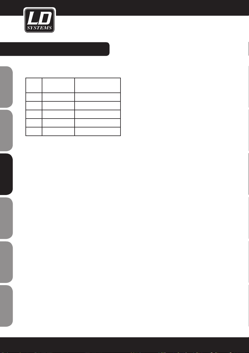
CARACTÉRISTIQUES:
SYSTÈME
Bandes de fréquences et niveau HF émetteur
Ban-deValeurs Niveau HF émetteur
UA 518-548 MHz 13dBm
UB 630-660 MHz 13dBm
UC 740-770 MHz 10dBm
UD 800-822 MHz 10dBm
UE 838-865 MHz 10dBm
Portée, dans des conditions typiques:
80 m
(la valeur de portée effectivement obtenue
dépend de l'absorption, des réflexions et des
interférences subies par le signal HF).
Réponse en fréquence audio:
60 Hz - 16 kHz
Taux de distorsion (à 1 kHz)
<1%
Gamme dynamique:
>90 dB (A)
Température d'utilisation:
-10°C à +50°C
(avec certaines piles, ces valeurs peuvent être
moins favorables)
ÉMETTEUR DE POCHE
Niveau audio d'entrée maximal:
0dBV maxi (position gain Micro)
+10dBV maxi (position gain 0dB)
+20dBV maxi (position gain -10dB)
Gamme de réglage de gain:
30 dB
Impédance d'entrée:
470 kΩ
Dimensions (H x L x P):
89 x 65 x 24 mm
Poids:
85 g sans les piles
Alimentation:
2 piles alcalines ou 2 accumulateurs type LR06 [AA]
Autonomie sur piles:
Jusqu'à 13h avec piles alcalines
ÉMETTEUR À MAIN
Dimensions (avec capsule micro):
longueur 243mm, diamètre 50mm
Poids:
300 g
Alimentation:
2 piles alcalines ou 2 accumulateurs type
LR06 [AA]
Autonomie sur piles:
Jusqu'à 14h avec piles alcalines
RÉCEPTEUR
Niveau de sortie audio :
sur XLR symétrique: - 12 dBV
sur jack 6,35mm: - 18 dBV
Impédance de sortie:
XLR: 200 Ohms
Jack 6,35mm: 1 kohm
Câblage du connecteur XLR:
Point 1: Masse
Point 2: (+)
Point 3: (-)
Dimensions (H x L x P):
44 x 212 x 160 mm
Poids:
900 g
Alimentation:
LDWS1000: 12 à 18 V continus, 500mA (par
adaptateur externe)
Double récepteur LDWS1000: 12 à 18 V continus, 1000 mA (par adaptateur externe)
Nos produits sont soumis à un processus de
développement et d'amélioration constant.
Pour cette raison, leurs caractéristiques techniques sont susceptibles de modification sans
préavis.
56
FRANCAISFRANCAIS FRANCAISFRANCAIS
ENGLISHDEUTSCHFRANCAIS
ESPAÑOLITALIANOPOLSKI
Page 57

57
ENGLISHDEUTSCHFRANCAIS
FRANCAISFRANCAIS FRANCAISFRANCAIS
ESPAÑOLITALIANOPOLSKI
Page 58

58
DECLARATIONS DU FABRICANT:
GARANTIE LIMITEE
Cette garantie limitée est applicable aux produits de marque Adam Hall, LD Systems, Defender, Palmer et
Eminence.
Elle ne concerne pas les droits statutaires relatifs à la garantie envers le vendeur. En fait, elle justifie des
requêtes en garantie indépendantes supplémentairees envers Adam Hall.
Adam Hall garantit que le produit Adam Hall que vous avez acheté auprès d’Adam Hall ou d’un revendeur
autorisé est dépourvu de défaut, au niveau des composants ou de la fabrication, pour une utilisation normale,
sur une durée de 2 ou 5 ans à partir de la date d’achat.
La période de garantie limitée démarre à partir de la date d’achat. Pour accéder à des réparations sous garantie, vous devrez fournir la preuve de la date d’achat. Par exemple, une facture ou bon de livraison daté, mentionnant en clair la date d’achat. Au cas où les produits des marques citées ci-avant nécessiteraient une réparation
pendant la période de garantie limitée, vous avez droit à des réparations sous garantie, conformément aux
termes et conditions exposées dans ce document.
Cette garantie limitée n’est applicable qu’à l’acheteur original de ce produit de marque Adam Hall: elle n’est
pas transmissible aux propriétaires ultérieurs de l’appareil. Pendant toute la période de garantie limitée, Adam
Hall réparera ou remplacera les composants défectueux ou le produit lui-même. Tous les composants ou appareils défectueux remplacés sous garantie deviennent la propriété de Adam Hall.
Dans le cas improbable où votre produit Adam Hall connaîtrait des défaillances à répétition, Adam Hall, à sa
discrétion, peut choisir de mettre à votre disposition un appareil de remplacement de son choix, au moins
équivalent à votre produit de marque Adam Hall en termes de performances matérielles.
Adam Hall ne garantit pas que l’utilisation de ce produit ne sera soumise à aucune interruption ni erreur. Adam
Hall n’est pas responsable des dommages occasionnés par le non-respect des instructions contenues dans le
manuel d’utilisation livré avec le produit de marque Adam Hall.
Cette garantie limitée ne s’applique pas:
- aux pièces d’usure (par exemple, un accumulateur)
- à tout produit sur lequel le numéro de série a été enlevé, ou à tout produit endommagé ou rendu défectueux à
la suite d’un accident
- en cas de utilisation, d’utilisation abusive, ou d’autres causes externes
- en cas d’utilisation hors des valeurs d’usage des paramètres, mentionnés dans le manuel utilisateur livré avec
le produit
- en cas d’utilisation de pièces de rechange non fabriquées ou non vendues par Adam Hall
- en cas de modification ou de réparation non assurée par Adam Hall
Ces termes et conditions constituent l’accord de garantie complet et exclusif entre vous et Adam Hall, concernant le produit de marque Adam Hall que vous avez acheté.
FRANCAISFRANCAIS FRANCAISFRANCAIS
ENGLISHDEUTSCHFRANCAIS
ESPAÑOLITALIANOPOLSKI
Page 59

59
DECLARATIONS DU FABRICANT:
RESPONSABILITE LIMITEE
Si votre appareil de marque Adam Hall ne fonctionne pas comme garanti ci avant, le seul recours, exclusif, est sa
réparation ou son remplacement. Dans le cadre de cette garantie limitée, la responsabilité financière maximale
d'Adam Hall est expressément limitée à la plus faible des deux sommes suivantes: prix payé pour le produit ou
coût de répararation ou de remplacement de tout composant matériel ne fonctionnant pas correctement dans
des conditions d'utilisation normale.
Adam Hall ne peut être tenu financièrement pour responsable de tout dommage causé par le produit ou par
sa défaillance- y compris toute perte de recettes ou de bénéfices ou tout dommage spécifique, incidentel ou
consécutif. Adam Hall n'est pas responsable financièrement en cas de requête émanant d'une tierce partie ou de
votre part pour une tierce partie.
Cette limitation de responsabilité financière s'applique en cas de demande de dommages et intérêts ou de
poursuites, dans le cadre de cette garantie limitée ou en cas de procédure (négligence et stricte responsabilité
produit), de non-respect de contrat, ou de toute autre procédure. Cette limitation de responsabilité financière ne
peut être annulée ou amendée par quiconque. Cette limitation de responsabilité financière sera effective même
si vous avez prévenu Adam Hall ou tout représentant autorisé de Adam Hall de la possibilité de tels dommages.
Toutefois, cette limitation de responsabilité financière ne s'applique pas en cas de blessures personnelles.
Cette garantie limitée vous donne des droits légaux spécifiques. Vous pouvez également avoir d'autres droits,
qui peuvent varier d'un état ou d'un pays à un autre. Nous vous conseillons de vous reporter aux lois applicables
dans votre état ou dans votre pays pour déterminer l'étendue exacte de vos droits.
DEMANDE DE REPARATIONS SOUS GARANTIE
Pour demander des réparations sous garantie pour votre produit, veuillez contacter Adam Hall ou le revendeur
agréé Adam Hall chez qui vous avez acheté le produit.
DECLARATION DE CONFORMITE CE
Ces appareils répondent aux exigences essentielles et aux autres dispositions pertinentes des directives 1999/5/
EC (R & TTE), 2004/108/EC (EMC) et 2006/95/EC (LVD). Pour plus d‘informations, consultez www.adamhall.com.
RECYCLAGE CORRECT DE CE PRODUIT (DECHET ELECTRIQUE)
(Applicable dans l'Union Européenne et autres pays européens pratiquant la collecte sélective des déchets)
La présence de ce logo sur le produit ou son manuel d'utilisation indique qu'en fin de vie, il ne doit pas être jeté
avec les autres déchets domestiques. Afin d'éviter toute atteinte à l'environnement ou à la santé humaine consécutive à une gestion incontrôlée des déchets, veuillez séparer ce produit des autres types de déchets, et assurer son
recyclage de manière responsable, afin de promouvoir la réutilisation durable des ressources matérielles.
Nous conseillons aux utilisateurs domestiques de contacter le revendeur chez qui ils ont acheté le produit, ou un
représentant du gouvernemental local, pour plus de détails sur le lieu de collecte et la façon de recycler cet appareil
dans le meilleur respect de l'environnement possible.
+Nous invitons les utilisateurs professionnels à contacter leur fournisseur et à vérifier les termes et conditions de
leur contrat d'achat. Ce produit ne doit pas être mélangé à d'autres déchets commerciaux lors de la collecte.
ENGLISHDEUTSCHFRANCAIS
FRANCAISFRANCAIS FRANCAISFRANCAIS
ESPAÑOLITALIANOPOLSKI
Page 60
60
DECLARATIONS DU FABRICANT:
DECLARATION WEEE
Votre produit LD-Systems a été développé et fabriqué avec des matériaux et des composants de haute qualité,
qui peuvent être recyclés et/ou réutilisés. Ce symbole indique que les appareils électriques et électroniques, à la
fin de leur durée de vie opérationnelle, doivent être gérés séparément des déchets ordinaires.
Veuillez apporter ce produit au point de collecte ou centre de recyclage local prévu pour de tels appareils. Vous
contribuerez ainsi à la protection de l'environnement dans lequel nous vivons tous.
BATTERIES ET ACCUMULATEURS
Les piles ou batteries rechargeable livrées avec l'appareil sont recyclables. Veuillez les jeter dans un bac à déchets
spécial, ou déposez-les chez votre revendeur spécialisé. Pour une meilleure protection de l'environnement, ne jetez
les piles que lorsqu'elles sont épuisées.
Adam Hall GmbH, tous droits réservés. Les caractéristiques techniques et les fonctions disponibles sur le produit
sont sujettes à modifications. La photocopie, la traduction et toute forme de copie, partielle ou intégrale, de ce
manuel utilisateur sont interdites.
FRANCAISFRANCAIS FRANCAISFRANCAIS
ENGLISHDEUTSCHFRANCAIS
ESPAÑOLITALIANOPOLSKI
Page 61

61
ENGLISHDEUTSCHFRANCAIS
FRANCAISFRANCAIS FRANCAISFRANCAIS
ESPAÑOLITALIANOPOLSKI
Page 62

62
Gracias por elegir LD-Systems!
Este producto se ha diseñado para ofrecer una fiabilidad y durabilidad óptima. Los productos de LD-Systems se
caracterizan por su gran calidad, avalada por el prestigio de la marca y una dilatada experiencia como fabricante.
Le rogamos que lea atentamente estas instrucciones para familiarizarse rápidamente con este producto LDSystems y aprovechar al máximo todas las funciones.
Si desea obtener información sobre LD-Systems, visite nuestro sitio web WWW.LD-SYSTEMS.COM
FRANCAISFRANCAIS FRANCAISFRANCAIS
ENGLISHDEUTSCHFRANCAIS
ESPAÑOLITALIANOPOLSKI
Page 63

LD WS1000(2)(X)
SISTEMA INALÁMBRICO TRUE DIVERSITY
16 CANALES UHF PLL
790,850 a 813,800 MHz
838,850 a 864,900 MHz (X-Version)
A A
B B
6
5
4
3
2
1
6
5
4
3
2
1
-5 -5
-3 -3
0 0
+3
+3
+6
+6
AF
AF
R F RF
V
V
SE T
IR
GR OUP CH ANNE L S CA N
FR EQ
GR OUP C
HA
NNE L S CA N
POWE
R
-2
0 -20
-10
-10
AS C
63
ENGLISHDEUTSCHFRANCAIS
FRANCAISFRANCAIS FRANCAISFRANCAIS
ESPAÑOLITALIANOPOLSKI
Page 64

04
64
MEDIDAS PREVENTIVAS:
ADVERTENCIA:
Para evitar el riesgo de descarga eléctrica, no retire la tapa (o el panel posterior). Este equipo no contiene piezas
que puedan ser reparadas por el usuario. Para cualquier tarea de mantenimiento o reparación, acuda a un
técnico cualificado.
El símbolo de rayo dentro de un triángulo equilátero advierte al usuario de la presencia de tensión
peligrosa sin aislamiento dentro de la carcasa del producto que pueden ser de magnitud suficiente
como para suponer un riesgo para las personas.
El símbolo de exclamación dentro de un triángulo equilátero advierte al usuario de la existencia de
importantes instrucciones de funcionamiento y mantenimiento (reparaciones) en la documentación
adjunta con el equipo.
ADVERTENCIA! ALTO VOLUMEN!
Este equipo se destina a un uso profesional. Por consiguiente, si se aplica a un uso comercial, estará sujeto a
las normas y reglamentos de la Asociación para la prevención de accidentes de su sector profesional. Como
fabricante, Adam Hall tiene la obligación de informar formalmente a los usuarios de la existencia de posibles
riesgos para la salud.
1. Lea atentamente las instrucciones de seguridad adjuntas así como las instrucciones de este documento.
2. Guarde todas las instrucciones.
3. Utilice el equipo únicamente según la finalidad prevista.
4. Procure seguir las normas vigentes sobre reciclaje de desechos. Separe los componentes de plástico y de
cartón del paquete para reciclarlos en sus contenedores respectivos.
5. Acuda a personal de servicio técnico cualificado en caso de que el equipo esté dañado, no funcione correctamente, se haya expuesto a lluvia o haya caído líquido sobre el equipo.
6. Evite colocar el equipo cerca de una fuente de calor, como hornos, radiadores o cualquier otro dispositivo
(incluidos los amplificadores). Mantenga una distancia suficiente entre los amplificadores y las paredes, estanterías, etc. para evitar cualquier sobrecalentamiento.
7. Una vez realizadas todas las conexiones, compruebe el cableado para evitar posibles daños o accidentes. No
utilice cables o conexiones que estén dañados.
8. En la instalación utilice solo soportes, fijaciones, estantes, mesas, etc. que sean estables y estén homologados. Compruebe que la estabilidad es adecuada para evitar la caída del equipo.
9. Compruebe la tensión indicada para el equipo antes de conectarlo. Cualquier error de conexión podría dañar el
equipo.
CA UT IO N
RISK OF EL ECT RIC SHOC K
DO N OT OP EN
FRANCAISFRANCAIS FRANCAISFRANCAIS
ENGLISHDEUTSCHFRANCAIS
ESPAÑOLITALIANOPOLSKI
Page 65
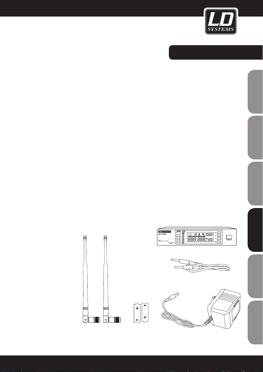
INTRODUCCIÓN:
TODOS LOS SISTEMAS
INCLUYEN:
Receptor (X)
2 baterías AA
Cable con jacks de 6,3 mm
Adaptador de corriente
2 antenas
Manual de usuario
Si desea establecer un sistema UHF avanzado, el WS-1000 es una solución excelente. El WS-1000 cuenta
con 160 bandas de frecuencia, por lo que resulta ideal para muchas aplicaciones, como espectáculos en vivo,
emisiones, salas de reuniones, toma de instrumentos, etc.
Mediante los botones y la pantalla LCD podrá realizar una instalación rápida y fácil. En este manual encontrará
todo lo necesario para operar el sistema de forma correcta y segura.
790,850 a 813,800 MHz
838,850 a 864,900 MHz (X-Version)
La mayoría de los países tienen reguladas las frecuencias empleadas para la transmisión inalámbrica de
datos,así como los equipos que pueden emplearlas. De este modo, se minimizan las interferencias perjudiciales.
Así, el sistema puede funcionar fácilmente en las dos bandas de frecuencias disponibles. Para evitar las interferencias de radiofrecuencia, el sistema se suministra con unos grupos de frecuencia predeterminados.
Si utiliza un único sistema, no es necesario cambiar la frecuencia operativa.
En cambio, si utiliza varios equipos simultáneamente, deberá configurar cada equipo en un canal distinto.
El sistema de grupos de canales optimiza la distribución de las frecuencias si se emplean simultáneamente
varios equipos. Con una banda de frecuencias podrán conectarse hasta 8 sistemas transmisor-receptor.
65
ENGLISHDEUTSCHFRANCAIS
FRANCAISFRANCAIS FRANCAISFRANCAIS
ESPAÑOLITALIANOPOLSKI
Page 66

SISTEMAS LD WS1000R:
LDWS1000BPG(X)
Sistema inalámbrico con petaca y
cable de guitarra
LDWS1000BPHH(X)
Sistema inalámbrico con 2 peta-
cas y 2 auriculares color piel
LDWS1000BPH(X)
Sistema inalámbrico con petaca y
auriculares
LDWS1000BPL(X)
Sistema inalámbrico con petaca y
micrófono Lavalier
LDWS1000HHD(X)
Sistema inalámbrico con micrófo-
no de mano dinámico
LDWS1000BPW(X)
Sistema inalámbrico con petaca
y micrófono para instrumentos de
viento
LDWS1000HHC(X)
Sistema inalámbrico con micrófono
de mano de condensador
66
FRANCAISFRANCAIS FRANCAISFRANCAIS
ENGLISHDEUTSCHFRANCAIS
ESPAÑOLITALIANOPOLSKI
Page 67

SISTEMAS LD WS1000R2:
LDWS1000BPHH2(X)
Sistema inalámbrico con 2 petacas y
2 auriculares color piel
LDWS1000HBH2(X)
Sistema inalámbrico con micrófono de
mano dinámico y auriculares
LDWS1000HHD2(X)
Sistema inalámbrico con 2 micró-
fonos de mano dinámicos
LDWS1000HHC2(X)
Sistema inalámbrico con 2 micrófo-
nos de mano de condensador
LDWS1000BPH2(X)
Sistema inalámbrico con 2 petacas y 2
auriculares
LDWS1000HHL2(X)
Sistema inalámbrico con micrófono de
mano dinámico y micrófono Lavalier
67
ENGLISHDEUTSCHFRANCAIS
FRANCAISFRANCAIS FRANCAISFRANCAIS
ESPAÑOLITALIANOPOLSKI
Page 68

RECEPTOR LD WS1000R:
PANELFRONTAL:
PANELPOSTERIOR:
1
RECEPTOR DE INFRARROJOS (IR)
2
INDICADOR DE RECEPCIÓN POR ANTENA A
Se ilumina al recibir señal para indicar que la
antena receptora A está activada.
3
INDICADOR DE NIVEL RF DE ANTENA A
4
INDICADOR DE NIVEL RF DE ANTENA B
5
INDICADOR DE RECEPCIÓN POR ANTENA B
Se ilumina al recibir señal para indicar que la
antena receptora B está activada.
6
INDICADOR DEL NIVEL DE AUDIO
7
PANTALLA LCD
Consulte la sección "Configuración del sistema"
más adelante.
1
CONECTOR DE ANTENA B,
50 Ω
2
CONECTOR XLR DE
SALIDA
3
JACK DE SALIDA DE 6,3 MM
8
BOTÓN ASC (SINC- RO)
Pulse este botón para conectar por infrarrojos
el transmisor y el receptor.
9
BOTÓN ABAJO
Utilice este botón para desplazarse por el menú.
10
BOTÓN ARRIBA
Utilice este botón para desplazarse por el menú.
11
BOTÓN DE CONFIGURACIÓN DEL SISTEMA
Consulte la sección "Configuración del
sistema" más adelante.
12
INTERRUPTOR DE ENCENDIDO
4
CONTROL DEL UMBRAL DE SILENCIO
En general, no es necesario cambiar el valor del umbral de silencio ya que
viene correctamente configurado de fábrica. Sin embargo, en caso de
interferencias, se puede anular este valor umbral utilizando un destornillador
para girar el potenciómetro en sentido horario hasta que se apague el LED
de señal RF.
5
TOMA DEL ADAPTADOR DE CORRIENTE
6
CONECTOR DE ANTENA A, 50 Ω
1
2
3 456 7
8
9
10
12
11
1
2
3
4
5
6
68
FRANCAISFRANCAIS FRANCAISFRANCAIS
ENGLISHDEUTSCHFRANCAIS
ESPAÑOLITALIANOPOLSKI
Page 69
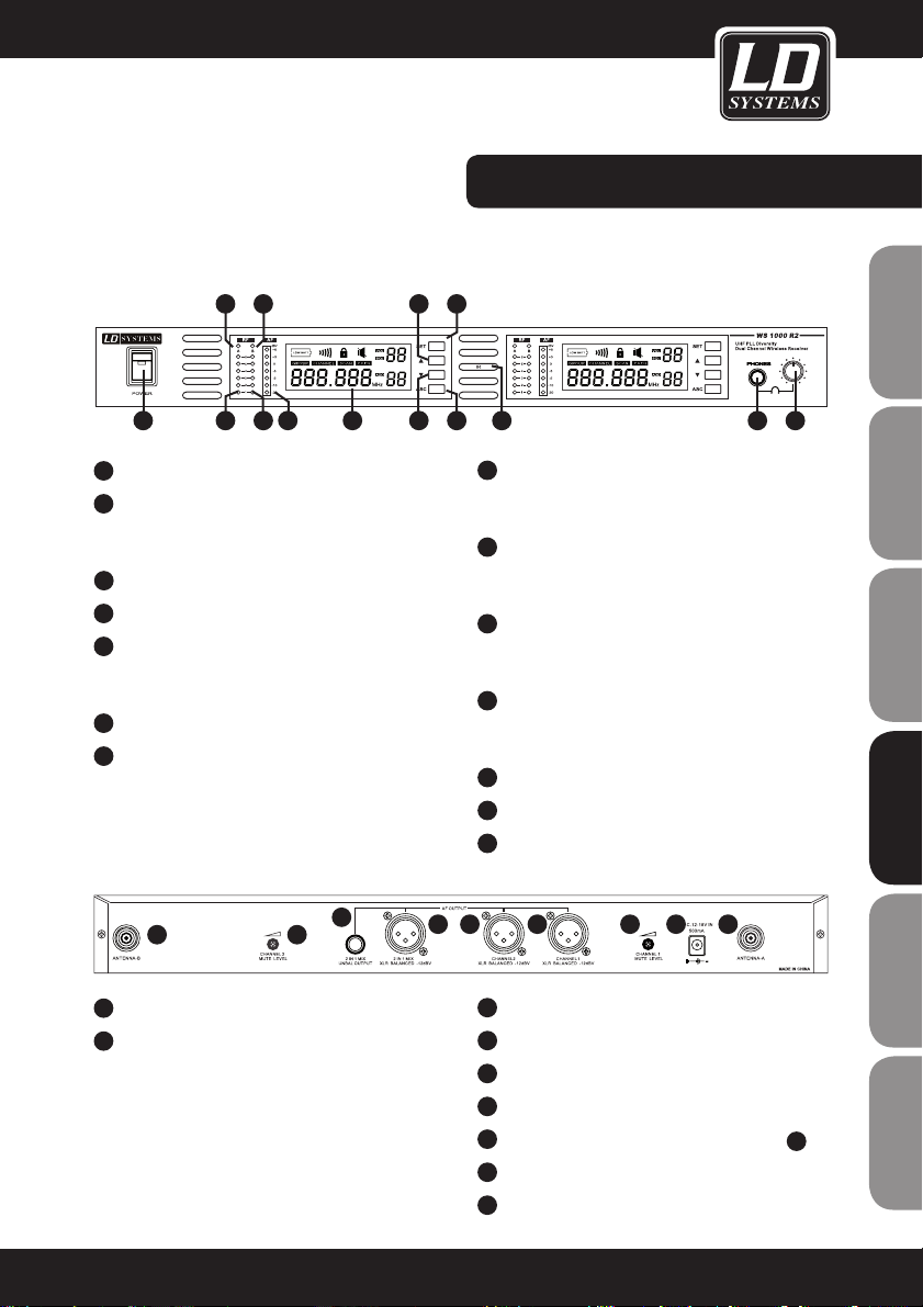
RECEPTOR LD WS1000R2:
PANELFRONTAL:
PANELPOSTERIOR:
1
INTERRUPTOR DE ENCENDIDO
2
INDICADOR DE RECEPCIÓN POR ANTENA A
Se ilumina para indicar que la antena receptora A
está activada.
3
INDICADOR DE NIVEL RF DE ANTENA A
4
INDICADOR DE NIVEL RF DE ANTENA B
5
INDICADOR DE RECEPCIÓN POR ANTENA B
Se ilumina para indicar que la antena receptora B
está activada.
6
INDICADOR DEL NIVEL DEL CANAL 1 DE AUDIO
7
PANTALLA LCD DE GRUPO Y CANAL 1
Consulte la sección "Configuración del sistema"
más adelante.
1
CONECTOR DE ANTENA B
2
UMBRAL DE SILENCIO DEL CANAL 2
Ajuste del valor del umbral de silencio del canal 2.
En general, no es necesario cambiar este valor, ya
que viene correctamente configurado de fábrica.
Sin embargo, en caso de interferencias, se puede
anular este valor umbral utilizando un destornillador para girar el potenciómetro en sentido horario
hasta que se apague el LED de señal RF.
8
BOTÓN ARRIBA
Utilice este botón para desplazarse por el
menú.
9
BOTÓN DE CONFIGURACIÓN DEL SISTEMA
Consulte la sección "Configuración del
sistema" más adelante.
10
BOTÓN ABAJO
Utilice este botón para desplazarse por el
menú.
11
BOTÓN ASC (SINCRONIZACIÓN)
Pulse este botón para conectar por infrarrojos
el transmisor y el receptor.
12
RECEPTOR DE INFRARROJOS (IR)
13
JACK PARA AURICULARES DE 6,3 MM
14
CONTROL DE VOLUMEN DE AURICULARES
3
JACK DE SALIDA DE 6,3 MM DE MEZCLA
4
XLR DE SALIDA DE MEZCLA
5
XLR DE SALIDA DEL CANAL 2
6
XLR DE SALIDA DEL CANAL 1
7
UMBRAL DE SILENCIO DEL CANAL 1 (VÉASE 2)
8
TOMA DEL ADAPTADOR DE CORRIENTE
9
CONECTOR DE ANTENA A
1 2
3
4 5 6 7 8 9
2315
4
8
1076
9
11
141312
69
ENGLISHDEUTSCHFRANCAIS
FRANCAISFRANCAIS FRANCAISFRANCAIS
ESPAÑOLITALIANOPOLSKI
Page 70

PETACA:
1
Antena
2
Pantalla LCD
Consulte la sección "Configuración del sistema" más adelante.
3
Indicador de Encendido/ASC
Se ilumina en color verde cuando el equipo está operativo
Parpadea en color verde al transmitir por infrarrojos
4
Indicador Mute
Si se ilumina en color rojo, indica que está en modo silencio
5
Botón de encendido/silencio
Pulse este botón durante 3 segundos para encender o apagar
el equipo
6
Receptor de IR
Se emplea para sincronizar la frecuencia mediante infrarrojos.
7
Botón Select
Consulte la sección "Configuración del sistema" más adelante.
8
Entrada de micro de 3 pines
9
Selector de ganancia de tres ajustes
Seleccione el ajuste apropiado para el instrumento
Mic: micrófono
0: guitarra con pastilla no activa
-10dB: guitarra con pastilla activa
USO DEL RECEPTOR DE PETACA
La petaca se cuelga del cinturón o de la cinta de la guitarra.
Para mejorar el agarre, se recomienda deslizar el clip de la petaca
hasta el fondo.
SUSTITUCIÓN DE LAS BATERÍAS
La vida útil de dos baterías alcalinas es de unas 8 horas. Sustituya
inmediatamente las baterías cuando parpadee el símbolo de batería
en la pantalla LCD.
parpadeante
1
2
3
4
5
7
6
9
1
8
verde
parpadeante
70
FRANCAISFRANCAIS FRANCAISFRANCAIS
ENGLISHDEUTSCHFRANCAIS
ESPAÑOLITALIANOPOLSKI
Page 71
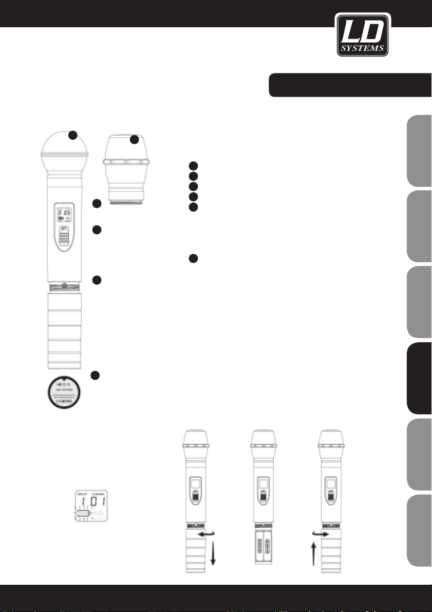
MICRO DE MANO:
COMPONENTES DEL MICRO:
1
Micrófono dinámico (WS-1000MD)
2
Micrófono de condensador (WS-1000MC)
3
Pantalla LCD
4
Interruptor de encendido
5
Potenciómetro de sensibilidad del micrófono
(girar a la izquierda para disminuir y a la derecha para
aumentar)
Consulte la sección "Configuración del sistema" más adelante.
Características del micro de mano:
6
Recibe una señal por infrarrojos para sincronizar transmisor y
receptor.
SUSTITUCIÓN DE BATERÍAS:
La vida útil de dos baterías alcalinas es de unas 14 horas. Sustituya inmediatamente las baterías cuando parpadee el símbolo de
batería en la pantalla LCD.
1
2
3
4
5
6
parpadeante
MD MC
71
ENGLISHDEUTSCHFRANCAIS
FRANCAISFRANCAIS FRANCAISFRANCAIS
ESPAÑOLITALIANOPOLSKI
Page 72
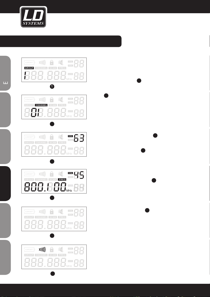
CONFIGURACIÓN DEL SISTEMA:
CONFIGURACIÓN DEL RECEPTOR:
Selección de grupo y canal: Pulse el botón “SET” hasta que aparezca
“GROUP” y luego pulse los botones de desplazamiento para seleccionar
uno de los grupos de frecuencias 1.
A continuación, pulse de nuevo “SET” hasta que aparezca “CHANNEL”
y luego utilice los botones de desplazamiento para seleccionar el canal
deseado
2
.
Para lograr mejores resultados cuando se utilizan varios sistemas, se
recomienda configurar todos los sistemas en el mismo grupo y seleccionar un canal distinto para cada uno.
Volumen del receptor: Si no hay nada seleccionado en la pantalla, puede
ajustar el volumen del sistema mediante los botones de desplazamiento. Aunque el nivel de salida de audio cuenta con 64 niveles, se
recomienda situarlo entre los niveles 42 y 45. 3.
Elementos de la pantalla: nivel de RF, número de grupo, número de
canal, frecuencia de funcionamiento
4
.
Sincronización por infrarrojos: Nota: Cuando se utilizan varios sistemas,
la frecuencia de cada sistema individual debe ser diferente. Encienda
el transmisor y abra el compartimento de la batería de la petaca para
acceder al sensor de infrarrojos (en los micros de mano dicho sensor se
encuentra en la parte inferior. Véase el punto 6 de la página anterior
de este manual). Coloque el transmisor y el receptor uno frente al otro,
de modo que los sensores de infrarrojos de ambos dispositivos estén
lo más cerca posible. Pulse el botón “ASC” del receptor y encienda el
transmisor. La sincronización se inicia automáticamente. Al pulsar el
botón “ASC”, el indicador IR se ilumina y el receptor envía la frecuencia
de sincronización durante 25 segundos
6
.
Al recibir esta frecuencia de sincronización, se iluminan las pantallas del
micrófono de mano y de la petaca, y se activa el icono de infrarrojos.
Advertencia: Durante el proceso, mantenga los dos dispositivos a una
distancia inferior a 0,5 metros. No puede utilizar este procedimiento
para sincronizar varios transmisores simultáneamente.
Función Auto-Scan: La serie WS1000 ofrece una función de búsqueda
automática de frecuencia que permite encontrar el canal sin interferencias dentro de un grupo. Pulse 3 veces el botón “SET” hasta que
aparezca “SCAN” en la pantalla. Pulse uno de los botones de desplazamiento para iniciar la búsqueda en la banda de frecuencias.
2
1
2
3
4
5
6
72
FRANCAISFRANCAIS FRANCAISFRANCAIS
ENGLISHDEUTSCHFRANCAIS
ESPAÑOLITALIANOPOLSKI
Page 73

CONFIGURACIÓN DEL SISTEMA:
Indicación del nivel de batería: Tanto el micrófono de mano como
la petaca muestran el nivel de batería en la pantalla (véase la
Figura 1).
Indicador de grupo y canal: Una vez establecida la conexión entre
los dos dispositivos, las pantallas de ambos dispositivos mostrarán
el grupo y el canal durante 5 segundos (véase la Figura 2).
A continuación, la pantalla regresa al modo normal mostrando el
estado de la batería y la frecuencia operativa (véase la Figura 3).
1
2
3
Micrófono de
mano
Petaca
73
ENGLISHDEUTSCHFRANCAIS
FRANCAISFRANCAIS FRANCAISFRANCAIS
ESPAÑOLITALIANOPOLSKI
Page 74

INSTALACIÓN EN RACK DE LOS RECEPTORES:
Un receptor
(con kit para rack WS100RK, opcional)
Kit para rack WS100RK con 2
orejas, 2 cables de conexión TNC
y 2 adaptadores TNC.
Dos receptores
(con kit para rack WS100RK2,
opcional)
Cuatro receptores
Con kit para rack WS100RK2
(opcional) y Splitter de antena
WS100AD (opcional)
Splitter de antena WS100AD con
10 cables de conexión TNC y 2
adaptadores TNC.
Accesorio para montaje en rack de
19"
74
FRANCAISFRANCAIS FRANCAISFRANCAIS
ENGLISHDEUTSCHFRANCAIS
ESPAÑOLITALIANOPOLSKI
Page 75

CONSEJOS PARA MEJORAR EL RENDIMIENTO:
Apunte el transmisor directamente al receptor ("línea directa" entre los dos equipos). No coloque el receptor cerca
de objetos metálicos o dispositivos electrónicos, como reproductores de CD, ordenadores, etc.
Coloque el receptor de modo que no esté justo delante de una pared y al menos 1 m por encima del suelo. Algunos
dispositivos, como los teléfonos móviles o los equipos de radio bidireccionales, pueden interferir en el funcionamiento entre el transmisor y el receptor, por lo que no se deben utilizar cerca del sistema.
PROBLEMA INDICACIÓN EN PANTALLA SOLUCIÓN
No hay audio o es demasiado
bajo
Transmisor: el indicador de encendido está apagado
Asegúrese de que el sistema está
conectado correctamente.
El indicador de encendido está
apagado
Asegúrese de que el adaptador
de corriente está correctamente
conectado tanto al receptor como a
la toma eléctrica.
Receptor: el indicador RF está
encendido
Suba el volumen. Aumente la
ganancia del transmisor.
Compruebe las conexiones del receptor y del amplificador o la mesa
de mezclas conectados.
Receptor: el indicador RF está
apagado
Transmisor: la pantalla está
encendida
No coloque el receptor cerca de objetos metálicos. Compruebe que no
hay obstáculos entre el transmisor y
el receptor, es decir, que hay "línea
directa".
Coloque el transmisor más cerca
del receptor. Asegúrese de que el
transmisor y el receptor estén en la
misma frecuencia.
Transmisor: el indicador del nivel de
batería parpadea
Sustituya las baterías
El audio está distorsionado o
viene con ruido
Receptor: el indicador RF está
encendido
Elimine la posible fuente de
interferencia: reproductores de CD,
ordenadores, generadores de efectos digitales, sistemas de monitoraje
"in ear", etc.
El audio cada vez sale más
distorsionado
Transmisor: el indicador del nivel de
batería parpadea
Sustituya las baterías
Hay una gran diferencia de nivel cuando la misma fuente de audio se
conecta por cable o cuando se utilizan otras guitarras o micrófonos.
Ajuste la ganancia en el transmisor
o el nivel de audio en el receptor.
75
ENGLISHDEUTSCHFRANCAIS
FRANCAISFRANCAIS FRANCAISFRANCAIS
ESPAÑOLITALIANOPOLSKI
Page 76
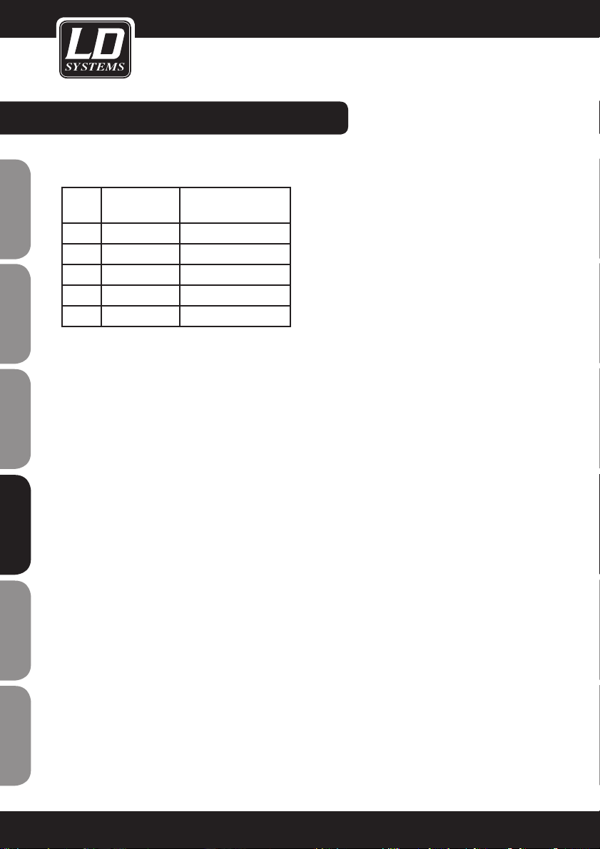
ESPECIFICACIONES TÉCNICAS:
SISTEMA
Banda de frecuencias y nivel RF del transmisor
Ban-daFrecuencias Nivel RF del trans-
misor
UA 518-548 MHz 13 dBm
UB 630-660 MHz 13 dBm
UC 740-770 MHz 10 dBm
UD 800-822 MHz 10 dBm
UE 838-865 MHz 10 dBm
Alcance en condiciones normales:
80 m
(Nota: el alcance real depende de la absorción de
la señal de RF, las reflexiones y las interferencias)
Respuesta de audio:
60 a 16.000 Hz
THD a 1 kHz:
<1%
Rango dinámico:
>90 dBA
Rango operativo de temperaturas:
-10 °C a +50 °C
(Nota: las características técnicas de la batería
pueden reducir este rango)
PETACA
Máximo nivel de entrada de audio:
máx. 0 dBV en la posición MIC
máx. +10 dBV en la posición 0dB
máx. +20 dBV en la posición -10dB
Rango de ajuste de la ganancia:
30 dB
Impedancia de entrada:
470 kΩ
Dimensiones (Al x An x F):
89 x 65 x 24 mm
Peso:
85 g sin baterías
Alimentación eléctrica:
2 pilas alcalinas AA o 2 pilas recargables AA
Duración de las baterías:
Hasta 13 horas con pilas alcalinas
MICRÓFONO DE MANO
Dimensiones, incluida la cápsula del
micro:
243 mm de longitud, 50 mm de diámetro
Peso:
300 g
Alimentación eléctrica:
2 pilas alcalinas AA o 2 pilas recargables AA
Duración de las baterías:
Hasta 14 horas con pilas alcalinas
RECEPTOR
Nivel de salida de audio:
XLR balanceada: -12 dBV
Jack de 6,3 mm: -18 dBV
Impedancia de salida:
XLR: 200 ohmios
Jack: 1 kohmio
Pineado del conector XLR:
Pin 1: Masa
Pin 2: (+)
Pin 3: (-)
Dimensiones (Al x An x F):
44 x 212 x 160 mm
Peso:
900 g
Fuente de alimentación:
LDWS1000: de 12 a 18 VDC, 500 mA (mediante adaptador de alimentación externo)
2 receptores LDWS1000: de 12 a 18 VDC,
1.000 mA (mediante adaptador de alimentación externo)
Dado que trabajamos constantemente en mejorar nuestros productos, las especificaciones
técnicas pueden variar sin previo aviso.
76
FRANCAISFRANCAIS FRANCAISFRANCAIS
ENGLISHDEUTSCHFRANCAIS
ESPAÑOLITALIANOPOLSKI
Page 77

77
ENGLISHDEUTSCHFRANCAIS
FRANCAISFRANCAIS FRANCAISFRANCAIS
ESPAÑOLITALIANOPOLSKI
Page 78

78
DECLARACIÓN DEL FABRICANTE:
GARANTÍA LIMITADA
Esta garantía limitada se aplica a los productos de la marca Adam Hall, LD Systems, Defender, Palmer y Eminence.
No afecta a los derechos de garantía legal que asume el vendedor. De hecho, le concede al usuario derechos
adicionales ante Adam Hall, independientes de la garantía legal.
Adam Hall garantiza que el producto que ha adquirido de Adam Hall o de cualquier distribuidor autorizado de
Adam Hall estará exento de defectos de material y mano de obra, en condiciones normales de uso, durante un
período de 2 o 5 años a partir de la fecha de compra.
La garantía limitada entra en vigor el día de la fecha de compra. Para tener derecho a esta garantía será necesario presentar un justificante de compra válido en el que figure la fecha de compra del producto, por ejemplo,
la factura o el albarán de entrega. Si el producto que ha adquirido necesitara una reparación durante la vigencia
de la garantía limitada, tendrá derecho a obtener los servicios de garantía conforme a los términos y condiciones
establecidos en este documento.
Esta garantía limitada se aplica únicamente al comprador original de este producto de Adam Hall y no se puede
transferir a terceras personas a las que el comprador haya cedido la propiedad del producto. Durante el periodo
de garantía limitada, Adam Hall se compromete a reparar o sustituir las piezas defectuosas del producto. Todas
las piezas o componentes retirados durante la reparación pasarán a ser propiedad de Adam Hall.
En el caso poco probable de que se produzca un fallo recurrente en el producto adquirido, Adam Hall, a su entera
discreción, podrá optar por sustituir dicho producto por otro de similares características.
Adam Hall no garantiza el funcionamiento ininterrumpido y sin fallos de este producto. Adam Hall no se hace
responsable de los posibles daños ocasionados por no seguir las instrucciones de uso suministradas con el
producto Adam Hall.
Esta garantía limitada no se aplica:
- en caso de desgaste normal de los consumibles (baterías, etc.)
- a los productos cuyo número de serie ha sido borrado, o que han quedado dañados y defectuosos debido a un
accidente
- en caso de defectos ocasionados por una incorrecta utilización o manipulación, o cualquier otra causa ajena
- en caso de utilización del producto no conforme con los parámetros establecidos en la documentación facilitada con el producto
- en caso de utilización de piezas de repuesto no fabricadas o vendidas por Adam Hall
- si el producto ha sido modificado o reparado por personal no autorizado por Adam Hall
Estos términos y condiciones constituyen el acuerdo de garantía íntegro y exclusivo entre usted y Adam Hall en
relación con el producto Adam Hall que acaba de adquirir.
FRANCAISFRANCAIS FRANCAISFRANCAIS
ENGLISHDEUTSCHFRANCAIS
ESPAÑOLITALIANOPOLSKI
Page 79

79
DECLARACIÓN DEL FABRICANTE:
LIMITACIÓN DE RESPONSABILIDAD
Si su producto Adam Hall no funciona de acuerdo con las garantías mencionadas arriba, tendrá derecho exclusivamente a la reparación o sustitución del mismo. La responsabilidad máxima de Adam Hall en virtud de los términos de esta garantía está limitada al menor importe que resulte del precio de compra del producto, del coste
de la reparación o la sustitución de las piezas que han dejado de funcionar en condiciones normales de uso.
Adam Hall no será responsable de cualquier daño causado por el producto o por el mal funcionamiento del
producto, incluidas la pérdida de ganancias, la pérdida de ahorros o cualquier consecuencia derivada de dichas
pérdidas. Adam Hall no se hará responsable de ninguna reclamación presentada por un tercero o por el comprador inicial en nombre de un tercero.
Esta limitación de responsabilidad se aplicará con independencia de que se solicite una indemnización por daños
y perjuicios, o se presenten reclamaciones por negligencia, contractuales o de cualquier otra índole, y no podrá
ser derogada o modificada. Esta limitación de responsabilidad será efectiva incluso en el caso de que el comprador hubiese avisado previamente a Adam Hall o a alguno de sus representantes de la posibilidad de reclamar
daños y perjuicios. No obstante, esta limitación de responsabilidad no tendrá efecto en caso de reclamación por
daños personales.
Esta garantía limitada le otorga derechos legales específicos. Puede que posea derechos adicionales conforme a
la legislación del país o Estado en el que se encuentre. Le recomendamos que consulte la legislación vigente en
su país o Estado para conocer el alcance de sus derechos.
APLICACIÓN DE LA GARANTÍA
Para solicitar asistencia técnica en relación con el producto en garantía, póngase en contacto con Adam Hall o
con el distribuidor autorizado donde adquirió el producto.
DECLARACIÓN CE DE CONFORMIDAD
Estos dispositivos cumplen con los requisitos esenciales y otras disposiciones pertinentes de las Directivas
1999/5/EC (R & TTE), 2004/108/EC (EMC) y 2006/95/EC (LVD). Para más información, consulte www.adamhall.
com.
ELIMINACIÓN CORRECTA DE ESTE PRODUCTO (DESECHOS ELÉCTRICOS)
(Aplicable en la Unión Europea y en los países europeos que dispongan de un sistema de recogida selectiva)
El símbolo que aparece sobre el producto o en la documentación adjunta indica que, al final de su vida útil, no deberá desecharse con los demás residuos domésticos. Para evitar posibles efectos negativos en el medio ambiente y
en la salud humana debidos al vertido incontrolado de desechos, no mezcle este producto con los demás residuos.
La recogida selectiva ayuda a su posterior reciclaje y fomenta la reutilización sostenible de los componentes de
este equipo.
Si usted es un particular, deberá ponerse en contacto con el distribuidor donde adquirió este producto, o con el
ayuntamiento, para informarse sobre el reciclaje adecuado de este equipo.
Si usted es una empresa, deberá ponerse en contacto con su proveedor e informarse sobre los términos y condiciones de su contrato de compra-venta. Este producto no debe mezclarse con otros residuos industriales.
ENGLISHDEUTSCHFRANCAIS
FRANCAISFRANCAIS FRANCAISFRANCAIS
ESPAÑOLITALIANOPOLSKI
Page 80

80
DECLARACIÓN DEL FABRICANTE:
DECLARACIÓN SOBRE WEEE
Este producto LD-Systems se ha desarrollado y fabricado con materiales y componentes de alta calidad que se
pueden reciclar o reutilizar. Este símbolo indica que los equipos eléctricos y electrónicos deben separarse del
resto de residuos comunes al final de su vida útil.
Para desechar este producto, llévelo al punto de recogida municipal o al centro de reciclaje específico para este
tipo de equipos. De este modo, contribuirá a proteger el medioambiente.
PILAS Y ACUMULADORES
Las pilas suministradas o las pilas recargables se pueden reciclar. Para desecharlas, deposítelas en un contenedor
especial o entréguelas a su proveedor especializado. Para proteger el medioambiente, deseche sólo pilas gastadas.
Adam Hall GmbH. Todos los derechos reservados. Los datos técnicos y las características funcionales del producto están sujetos a modificaciones. Se prohíbe la fotocopia, traducción y cualquier otra forma de reproducción
parcial o total de este manual de usuario.
FRANCAISFRANCAIS FRANCAISFRANCAIS
ENGLISHDEUTSCHFRANCAIS
ESPAÑOLITALIANOPOLSKI
Page 81

81
ENGLISHDEUTSCHFRANCAIS
FRANCAISFRANCAIS FRANCAISFRANCAIS
ESPAÑOLITALIANOPOLSKI
Page 82

82
Acquistando un prodotto LD Systems avete fatto la scelta giusta!
Quest’apparecchio è stato sviluppato e prodotto secondo elevati standard qualitativi che garantiscono un funzionamento regolare per molti anni. Per questo motivo LD Systems, con il suo nome e la pluriennale esperienza,
rappresenta un’azienda produttrice di prodotti audio di qualità.
Leggete attentamente questo manuale d’uso per utilizzare al meglio il vostro nuovo amplificatore LD Systems.
Per ulteriori informazioni sui prodotti LD Systems consultate il nostro sito internet WWW.LD-SYSTEMS.COM
FRANCAISFRANCAIS FRANCAISFRANCAIS
ENGLISHDEUTSCHFRANCAIS
ESPAÑOLITALIANOPOLSKI
Page 83
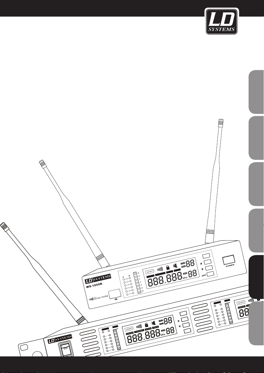
LD WS1000(2)(X)
16 CHN UHF PLL TRUE DIVERSITY WIRELESS SYSTEM
790.850 - 813.800 MHz
838.850 - 864.900 MHz (X-Version)
A A
B B
6
5
4
3
2
1
6
5
4
3
2
1
-5 -5
-3 -3
0 0
+3
+3
+6
+6
AF
AF
R F RF
V
V
SE T
IR
GR OUP CH ANNE L S CA N
FR EQ
GR OUP C
HA
NNE L S CA N
POWE
R
-2
0 -20
-10
-10
AS C
83
ENGLISHDEUTSCHFRANCAIS
FRANCAISFRANCAIS FRANCAISFRANCAIS
ESPAÑOLITALIANOPOLSKI
Page 84

04
84
AVVERTENZE:
1. Attenersi alle avvertenze di sicurezza e leggere attentamente il presente manuale.
2. Conservare in un luogo sicuro tutte le avvertenze e le indicazioni.
3. Utilizzare l'apparecchio solo nei modi previsti dal manuale.
4. Rispettare le leggi in vigore nel paese di installazione sullo smaltimento. Separare la plastica dalla carta e dal
cartone per lo smaltimento.
5. Se l'apparecchio non funziona più correttamente, è stato esposto a liquidi o è stato in qualche modo danneggiato, rivolgersi esclusivamente a personale autorizzato per le dovute riparazioni.
6. Tenere l'apparecchio lontano da fonti di calore come stufe, termosifoni o altro (anche amplificatori). Controllare
che l'apparecchio sia sempre posizionato in modo tale che si possa raffreddare e che non si surriscaldi.
7. Controllare tutte le linee alle quali l'apparecchio è collegato per evitare danni o incidenti.
8 Utilizzare esclusivamente supporti stabili e adeguati per fissare l'apparecchio. Verificare che l'apparecchio sia
installato in modo stabile e non possa cadere.
ATTENZIONE:
Non togliere mai il coperchio di protezione: pericolo di scosse elettriche.
All'interno dell'apparecchio non ci sono parti che possono essere controllate o riparate dall'utente.
Per la riparazione rivolgersi esclusivamente a personale qualificato.
Questo simbolo avverte del pericolo dovuto alla presenza di una tensione pericolosa non isolata all'interno dell'apparecchio che può causare scosse pericolose.
Questo simbolo indica avvertenze e istruzioni d'uso importanti.
Attenzione! Volume alto!
Questi sistemi di trasmissione vengono utilizzati dall'utente per scopi professionali. Pertanto l'uso per scopi commerciali è soggetto alle norme e ai regolamenti delle associazioni di categoria competenti. Adam Hall, in qualità
di produttore, è perciò obbligato a segnalare espressamente la presenza di possibili rischi per la salute.
Questi altoparlanti possono generare elevate pressioni sonore. 85db è la pressione sonora massima che per
legge può essere esercitata sull'udito umano in una giornata lavorativa. Questo valore è stato stabilito in base a
quanto rilevato nel campo della medicina del lavoro. Suoni di maggiore intensità o più prolungati possono provocare danni all'apparato uditivo. Nel caso di volumi più elevati sarà necessario diminuire il tempo di esposizione
per evitare eventuali danni all'udito. Alcuni campanelli di allarme che indicano una prolungata esposizione a
suoni troppo forti sono:
- La presenza di suoni o fischi all'interno dell'orecchio!
- La sensazione di non sentire più i suoni ad alta frequenza!
CAU TI ON
RIS KO FE LECT RIC S HOC K
DON OT O PEN
FRANCAISFRANCAIS FRANCAISFRANCAIS
ENGLISHDEUTSCHFRANCAIS
ESPAÑOLITALIANOPOLSKI
Page 85

INTRODUZIONE:
TUTTI I SISTEMI
CONTENGONO:
ricevitore (X)
2 batterie AA
cavo jack audio da 6,3 mm
alimentatore
due antenne
Manuale d'uso
Il sistema WS-1000 è la soluzione ideale per coloro che vogliono installare un innovativo sistema UHF. Con le
sue 160 bande di frequenza, il WS-1000 è adatto a molteplici utilizzi, come ad esempio show live, broadcast,
meetings, strumenti, etc.
Pulsanti Touch e display LCD permettono un'installazione veloce e facile. In questo manuale sono contenute tutte
le informazioni importanti per utilizzare il sistema in modo corretto e in sicurezza.
790,850 - 813,800 MHz
838,850 - 864.900 MHz (X-Version)
La maggior parte dei paesi regola le frequenze che vengono utilizzate per il trasferimento dei dati in modalità
senza fili. Queste regole stabiliscono quali apparecchi possono funzionare su quali di frequenza. In questo modo
le interferenze vengono ridotte al minimo. Per far sì che il sistema funzioni senza problemi, vengono messe a
disposizione due diverse bande di frequenza. Per proteggere il dispositivo contro interferenze RF, questo viene
distribuito con dei gruppi di frequenze preimpostati.
Se si utilizza un solo sistema, non dovrebbe essere necessario modificare la frequenza di funzionamento.
Se si utilizzano più apparecchi allo stesso tempo, è necessario impostare un canale diverso per ogni apparecchio.
Il sistema a gruppi e canali permette uno smistamento ottimale nelle frequenze in caso di utilizzo di più sistemi
allo stesso tempo. Con un'unica banda di frequenza è possibile utilizzare fino a 8 sistemi individuali di trasmissione/ricezione nello stesso impianto.
85
ENGLISHDEUTSCHFRANCAIS
FRANCAISFRANCAIS FRANCAISFRANCAIS
ESPAÑOLITALIANOPOLSKI
Page 86
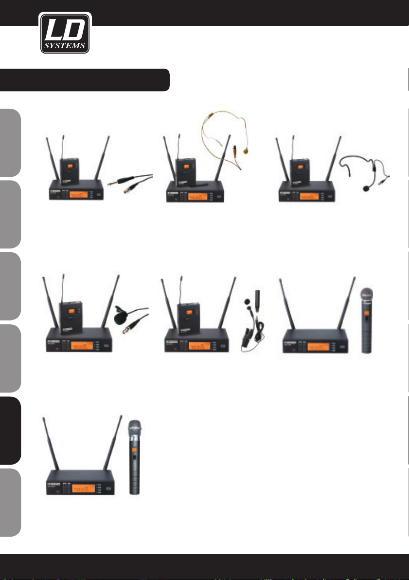
LD WS1000R PARTS:
LDWS1000BPG(X)
Sistema per radiomicrofono con
belt pack e cavo per chitarra
LDWS1000BPHH(X)
Sistema per radiomicrofono con 2
belt pack e 2 headset color carne
LDWS1000BPH(X)
Sistema per radiomicrofono con
belt pack e headset
LDWS1000BPL(X)
Sistema per radiomicrofono con
belt pack e microfono Lavalier
LDWS1000HHD(X)
Sistema per radiomicrofono con
microfono a mano dinamico
LDWS1000BPW(X)
Sistema per radiomicrofono con belt
pack e microfono per strumenti a fiato
LDWS1000HHC(X)
Sistema per radiomicrofono con
microfono a mano a condensatore
86
FRANCAISFRANCAIS FRANCAISFRANCAIS
ENGLISHDEUTSCHFRANCAIS
ESPAÑOLITALIANOPOLSKI
Page 87

LD WS1000R2 PARTS:
LDWS1000BPHH2(X)
Sistema per radiomicrofono con 2
belt pack e 2 headset color carne
LDWS1000HBH2(X)
Sistema per radiomicrofono con microfono a mano dinamico e headset
LDWS1000HHD2(X)
Sistema per radiomicrofono con 2
microfoni a mano dinamici
LDWS1000HHC2(X)
Sistema per radiomicrofono con 2
microfoni a mano a condensatore
LDWS1000BPH2(X)
Sistema per radiomicrofono con 2 belt
pack e 2 headset
LDWS1000HHL2(X)
Sistema per radiomicrofono con mi-
crofono a mano dinamico e microfono
Lavalier
87
ENGLISHDEUTSCHFRANCAIS
FRANCAISFRANCAIS FRANCAISFRANCAIS
ESPAÑOLITALIANOPOLSKI
Page 88

RICEVITORE LD WS1000R:
FRONTE:
RETRO
1
CONNETTORE PER
ANTENNA B 50 Ω
2
USCITA XLR
3
USCITA DA 6,3 MM
4
REGOLAZIONE DI PRECISIONE DEL VALORE MUTE THRESHOLD
Regolazione di precisione del valore Mute threshold. Generalmente non vi è
alcuna necessità di modificare questo valore in quanto impostato
correttamente di fabbrica. Tuttavia, qualora si ricevano segnali disturbati, è
possibile alzare questo valore threshold spostando il regolatore verso destra
fino a quando la spia del segnale RF si spegne.
5
AC ADATTATORE CONNETTORE
6
CONNETTORE PER ANTENNA A 50 Ω
1
2
3 456 7
8
9
10
12
11
1
2
3
4
5
6
1
PORTA INFRAROSSI (IR)
2
SPIA RICEZIONE ANTENNA A
La spia si accende durante la ricezione quando il
ricevitore A è acceso.
3
INDICATORE INTENSITÀ DEL SEGNALE
ANTENNA A
4
INDICATORE INTENSITÀ DEL SEGNALE
ANTENNA B
5
SPIA RICEZIONE ANTENNA B
La spia si accende quando l'antenna B è accesa.
6
INDICATORE CANALE AUDIO
7
DISPLAY LCD CANALE
Si prega di controllare nelle impostazioni di sistema.
8
TASTO SYNC (ASC)
Premere questo tasto per stabilire una
connessione a infrarossi tra il trasmettitore e il
ricevitore.
9
TASTO FRECCIA GIÙ
Utilizzare questo tasto per navigare nel menù.
10
TASTO FRECCIA SU
Utilizzare questo tasto per navigare nel menù.
11
TASTO IMPOSTAZIONI DI SISTEMA
Si prega di controllare nelle impostazioni di
sistema.
12
INTERRUTTORE ON/OFF
88
FRANCAISFRANCAIS FRANCAISFRANCAIS
ENGLISHDEUTSCHFRANCAIS
ESPAÑOLITALIANOPOLSKI
Page 89
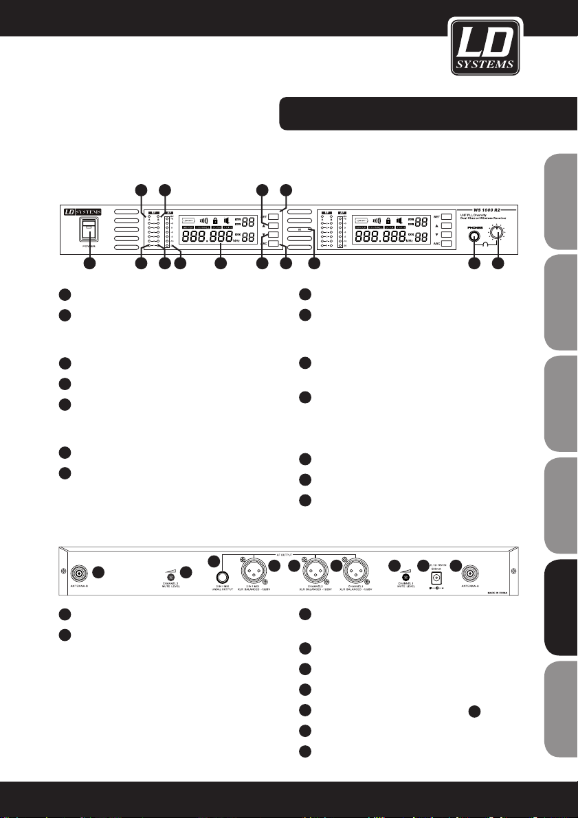
RICEVITORE LD WS1000R2:
FRONTE:
RETRO
1
INTERRUTTORE ON/OFF
2
SPIA RICEZIONE ANTENNA A
La spia si accende quando l'antenna A riceve un
segnale.
3
SPIA RF ANTENNA A
4
SPIA RF ANTENNA B
5
SPIA RICEZIONE ANTENNA B
La spia si accende quando l'antenna B riceve un
segnale.
6
INDICATORE LIVELLO CANALE AUDIO 1 AF
7
DISPLAY LCD CANALE/GRUPPO 1
Si prega di controllare le impostazioni in System
Setup.
1
CONNETTORE ANTENNA B
2
MUTE THRESHOLD CANALE 2
Regolazione di precisione del valore Mute Threshold
canale 2. Generalmente non vi è alcuna necessità di
modificare questo valore. Il valore è impostato
correttamente di fabbrica. Tuttavia, qualora si
ricevano segnali disturbati, è possibile alzare questo
valore Threshold quando il trasmettitore è spento
girando il regolatore verso destra fino a quando la
spia del segnale RF si spegne.
8
Utilizzare questo tasto per navigare nel menù.
9
TASTO SYSTEM SETUP
Si prega di controllare le impostazioni in
System Setup.
10
TASTO FRECCIA GIÙ
Utilizzare questo tasto per navigare nel menù.
11
TASTO SYNC (ASC)
Premere questo tasto per creare un
collegamento a infrarossi tra il ricevitore e il
trasmettitore.
12
PORTA INFRAROSSI (IR)
13
INGRESSO JACK CUFFIE DA 6,3 MM
14
VOLUME CUFFIE
3
USCITA JACK PER MIX PER CONNETTORI DA
6,3 MM
4
USCITA XLR PER MIX
5
USCITA XLR CANALE 2
6
USCITA XLR CANALE 1
7
MUTE THRESHOLD CANALE 1 (VEDI
2)
8
ALIMENTATORE CA
9
CONNETTORE PER ANTENNA A
1 2
3
4 5 6 7 8 9
2315
4
8
1076
9
11
141312
89
ENGLISHDEUTSCHFRANCAIS
FRANCAISFRANCAIS FRANCAISFRANCAIS
ESPAÑOLITALIANOPOLSKI
Page 90

BELTPACK:
1
Antenna
2
Display LCD
Si prega di controllare le impostazioni di sistema in "System
Setup" a pagina 7.
3
Spia Power/ASC
Spia verde accesa: l'apparecchio è in funzione
Spia verde lampeggiante: Trasmissione infrarossi in corso
4
Spia Mute
Se rossa, indica che la funzione Mute è attiva
5
Interruttore Power/Mute
Premere per 3 secondi per accendere o spegnere l'apparecchio
6
Porta infrarossi (IR)
Per ricevere frequenze di sincronizzazione via infrarossi.
7
Tasto Select
Si prega di controllare nelle impostazioni di sistema.
8
Ingresso microfono 3-pin
9
Il Bodypack permette di scegliere fra tre diverse impostazioni
del guadagno
Scegliere l'impostazione adatta al vostro strumento
Mic: microfono
0: chitarra con pick-up passivi
-10dB: chitarra con pick-up attivi
COME PORTARE IL TRASMETTITORE BELTPACK
Fissare il trasmettitore ad una cintura o a una tracolla della chitarra.
Per una migliore stabilità del trasmettitore è preferibile fissarlo
come mostrato nella prima figura infilandolo completamente cosicché la cintura risulti stretta dalla clip.
SOSTITUZIONE BATTERIE
Generalmente 2 batterie alcaline durano fino a 8 ore. Quando la
spia verde che indica lo stato delle batterie lampeggia, è necessario
procedere immediatamente con la loro sostituzione.
lampeggia!
1
2
3
4
5
7
6
9
1
8
spia
verde
lampeggiante
90
FRANCAISFRANCAIS FRANCAISFRANCAIS
ENGLISHDEUTSCHFRANCAIS
ESPAÑOLITALIANOPOLSKI
Page 91

TRASMETTITORE A MANO:
PROGRAMMAZIONE DEL TRASMETTITORE:
1
Microfono dinamico (WS-1000MD)
2
Microfono a condensatore (WS-1000MC)
3
Display LCD
4
Interruttore generale
5
Impostazione della sensibilità del microfono
(girando verso sinistra è minore, verso destra è maggiore)
Si prega di controllare nelle impostazioni di sistema.
Funzioni trasmettitore a mano:
6
Riceve segnali a infrarossi per sincronizzare il trasmettitore e il
ricevitore.
SOSTITUZIONE BATTERIE:
Generalmente 2 batterie alcaline durano fino a 14 ore. Quando
la spia che indica lo stato delle batterie lampeggia, è necessario
sostituirle immediatamente.
1
2
3
4
5
6
lampeggia!
MD MC
91
ENGLISHDEUTSCHFRANCAIS
FRANCAISFRANCAIS FRANCAISFRANCAIS
ESPAÑOLITALIANOPOLSKI
Page 92
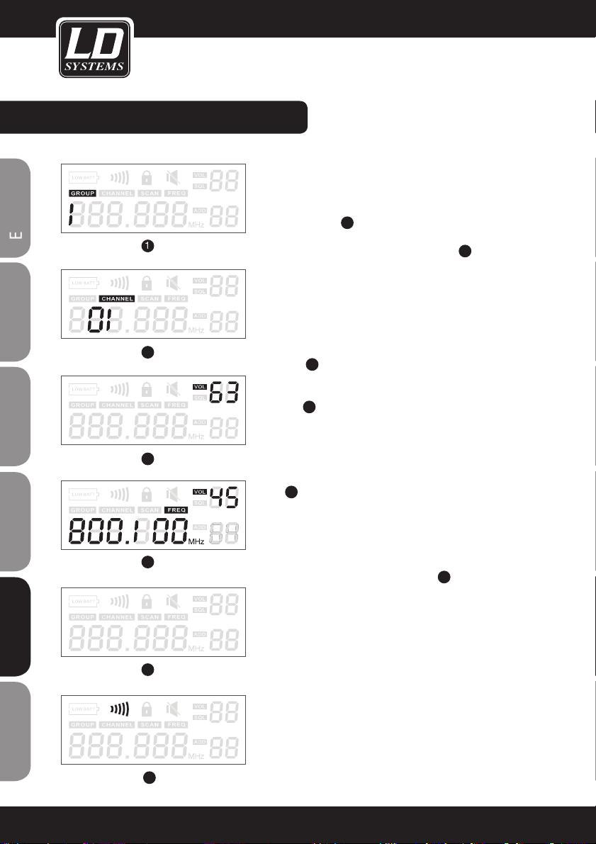
IMPOSTAZIONI DI SISTEMA:
PROGRAMMAZIONE DEL RICEVITORE:
Scelta del gruppo e del canale: Premere "SET" fino a quando non
appare la scritta "GROUP" , premere poi i tasti freccia per scegliere un
gruppo di frequenze 1.
Premere ancora "SET" fino a quando appare la scritta "CHANNEL" e
scegliere il canale desiderato usando i tasti freccia
2
.
Per ottenere migliori risultati con più sistemi, assegnare a tutti i
dispositivi lo stesso gruppo e impostare una frequenza diversa in
ognuno di essi.
Il volume del ricevitore: Quando non è selezionato altro sul display è
possibile regolare il volume del sistema utilizzando i tasti freccia. Il
volume è regolabile su 64 livelli. È consigliabile impostare il volume
tra 42 e 45
3
.
Display normale livello RF,group no,channel no, frequenza come
indicato in
4
.
Ricerca frequenze infrarossi: NB: Se si utilizzano più sistemi, ad
ogni sistema deve essere assegnato un indirizzo diverso. Spegnere
il trasmettitore e aprire il vano batteria (solo nel caso di bodypack;
i sistemi a mano hanno l'interfaccia IR sull'estremità inferiore, vedi
punto
6
della pagina precedente del presente manuale). Posizionare
il trasmettitore e il ricevitore uno di fronte all'altro in modo tale che
le interfacce IR di entrambi i dispositivi siano il più vicino possibile.
Premere il pulsante "ASC" e riaccendere il trasmettitore. Successivamente premere "ASC" anche sul trasmettitore. Ogni volta che viene
premuto il tasto ASC, la spia IR si accende e il ricevitore invia delle
frequenze di sincronizzazione per 25 secondi
6
.
Durante la ricezione di queste frequenze il trasmettitore a mano si illumina e sul Bodypack si accende l'intero display e il simbolo IR è attivo.
Attenzione: Durante questa procedura, entrambi i dispositivi dovrebbero stare ad una distanza inferiore a 0,5 metri. Con questa procedura
non è possibile sincronizzare più trasmettitori allo stesso tempo.
Funzione Auto-Scan: I dispositivi della serie WS1000 sono dotati della
funzione di scansione automatica delle frequenze. Questa funzione
permette di trovare le frequenze nitide all'interno di un gruppo.
Premere "SET" 3 volte fino a quando la scritta "SCAN" compare sul
display. Premere uno dei tasti freccia per inizializzare la ricerca delle
frequenze.
2
1
2
3
4
5
6
92
FRANCAISFRANCAIS FRANCAISFRANCAIS
ENGLISHDEUTSCHFRANCAIS
ESPAÑOLITALIANOPOLSKI
Page 93

IMPOSTAZIONI DI SISTEMA:
Stato della batteria: Sia il trasmettitore a mano sia quello bodypack mostrano lo stato della batteria sul display (vedi immagini
a lato 1)
Indicatore gruppo e canale: Una volta stabilito il collegamento tra
i dispositivi, sul display di entrambi compaiono per 5 secondi il
gruppo e il canale utilizzati 2. Subito dopo il display torna alla
modalità normale, nella quale vengono visualizzati lo stato della
batteria e la frequenza di funzionamento (vedi immagini a lato 3).
1
2
3
Trasmettitore
a mano
Trasmettitore
Bodypack
93
ENGLISHDEUTSCHFRANCAIS
FRANCAISFRANCAIS FRANCAISFRANCAIS
ESPAÑOLITALIANOPOLSKI
Page 94

INSTALLAZIONE RACK DEL RICEVITORE:
Un ricevitore
(con kit per rack WS100RK,
opzionale)
Kit per rack WS100RK con 2
supporti angolari, 2 cavi di connessione TNC e 2 adattatori TNC.
Due ricevitori
(con kit per rack WS100RK,
opzionale)
Quattro ricevitori
Con kit di fissaggio WS100RK2
(opzionale) e splitter per antenne
WS100AD (opzionale)
Splitter per antenna WS100AD con
10 cavi di connessione TNC e 2
adattatori TNC.
Angolari da 19"
94
FRANCAISFRANCAIS FRANCAISFRANCAIS
ENGLISHDEUTSCHFRANCAIS
ESPAÑOLITALIANOPOLSKI
Page 95

CONSIGLI PER UN MIGLIORE FUNZIONAMENTO:
Orientare il trasmettitore verso il ricevitore affinché ci sia "contatto visivo" tra i dispositivi. Non posizionare il ricevitore vicino a oggetti/superfici metalliche o vicino ad apparecchi digitali (lettori CD, Computer, etc.).
Posizionare il ricevitore in modo tale che non sia a stretto contatto con una parete e che sia ad almeno 1 m di
altezza dal pavimento. Telefoni cellulari, apparecchiature radio bidirezionali o apparecchi simili possono disturbare
il collegamento radio tra il trasmettitore e il ricevitore e non devono perciò essere utilizzate vicino al sistema di
trasmissione.
PROBLEMA SPIE LUMINOSE SOLUZIONE
Nessun suono o suono
troppo basso
Trasmettitore: la spia on/off non si
accende
Assicurarsi che l'apparecchio sia collegato correttamente.
Spia di rete "Power" spenta Assicurarsi che l'alimentatore CA sia
collegato correttamente all'apparecchio e
che l'altra estremità sia inserita correttamente sul retro.
Ricevitore: La spia HF è accesa
Alzare il volume. Alzare il valore di
guadagno del trasmettitore.
Verificare i collegamenti alla rete del
ricevitore e di amplificatori o mixer
collegati.
Ricevitore: La spia HF è spenta.
Trasmettitore: La spia è accesa
Non posizionare il ricevitore vicino a
oggetti metallici. Verificare che lo spazio
di trasmissione tra trasmettitore e ricevitore sia libero ("contatto visivo").
Avvicinare il trasmettitore al ricevitore.
Assicurarsi che il trasmettitore e il ricevitore utilizzino la stessa frequenza
Trasmettitore: L'indicatore dello stato
delle batterie è acceso
Sostituire le batterie
Distorsioni o interferenze
indesiderate
Ricevitore: La spia HF è accesa
Eliminare possibili fonti di interferenza
(lettori CD, computer, processori digitali
di effetti, sistemi in ear monitor, etc.)
Crescenti distorsioni Trasmettitore: L'indicatore dello stato
delle batterie è acceso
Sostituire le batterie
Chiara differenza di intensità quando il collegamento della stessa
sorgente avviene tramite cavo o in caso di collegamento di altre
chitarre o microfoni.
Impostare il valore di guadagno del
trasmettitore e il volume del ricevitore in
modo adeguato.
95
ENGLISHDEUTSCHFRANCAIS
FRANCAISFRANCAIS FRANCAISFRANCAIS
ESPAÑOLITALIANOPOLSKI
Page 96

SPECIFICHE TECNICHE:
SISTEMA
Campo di frequenza e livello trasmettitore RF
Ban-daRange Livello trasmettitore
RF
UA 518-548 MHz 13dBm
UB 630-660 MHz 13dBm
UC 740-770 MHz 10dBm
UD 800-822 MHz 10dBm
UE 838-865 MHz 10dBm
Raggio d'azione in condizioni normali:
80 m
(il raggio d'azione dipende da assorbimento,
riflessione e interferenze del segnale RF)
Banda di trasmissione audio:
60 – 16.000 Hz
Distorsione armonica totale a 1 kHz:
<1%
Intervallo dinamico:
>90 dB (A-weighted)
Temperatura di esercizio:
da -10°C a +50°C
(le proprietà di alcune batterie potrebbero restringere questo campo)
TRASMETTITORE TASCABILE
Massima intensità entrata audio:
massimo 0 dBV in posizione Mic-Gain
massimo +10 dBV con guadagno a 0 dB
massimo +20 dBV con guadagno a -10 dB
Regolazione guadagno:
30 dB
Impedenza di ingresso:
470 kΩ
Dimensioni (H x L x P):
89 x 65 x 24 mm
Peso:
85 g senza batterie
Funzionamento:
Con 2 batterie alcaline di tipo AA o due batterie
ricaricabili di tipo AA
Autonomia:
Fino a 13 ore con batterie alcaline
TRASMETTITORE A MANO
Dimensioni con di capsula del microfono
compresa:
243 mm lunghezza, 50 mm diametro
Peso:
300 g
Funzionamento:
Con 2 batterie alcaline di tipo AA o due batterie
ricaricabili di tipo AA
Autonomia:
Fino a 14 ore con batterie alcaline
RICEVITORE
Livello di uscita audio:
XLR simmetrico: - 12 dBV
Jack da 6,3 mm: - 18 dBV
Impedenza di uscita
XLR: 200 Ohm
Jack: 1 kOhm
Connessione XLR:
Pin 1: massa
Pin 2: (+)
Pin 3: (-)
Dimensioni (H x L x P):
44 x 212 x 160 mm
Peso:
900 g
Alimentazione:
LDWS1000: 12 – 18 V DC, 500 mA (Alimentazione tramite alimentatore di rete esterno)
LDWS1000 doppio ricevitore: 12 – 18 V DC,
1000 mA (Alimentazione tramite alimentatore
di rete esterno)
I nostri prodotti sono continuamente sottoposti a procedure di sviluppo e miglioramento.
Per questo motivo le caratteristiche tecniche
possono essere soggette a modifiche senza
preavviso.
96
FRANCAISFRANCAIS FRANCAISFRANCAIS
ENGLISHDEUTSCHFRANCAIS
ESPAÑOLITALIANOPOLSKI
Page 97

97
ENGLISHDEUTSCHFRANCAIS
FRANCAISFRANCAIS FRANCAISFRANCAIS
ESPAÑOLITALIANOPOLSKI
Page 98

98
GARANZIA DEL PRODUTTORE
Le seguenti condizioni di garanzia si applicano ai prodotti dei marchi Adam Hall, LD Systems, LD Premium,
Defender, Palmer e Eminence.
La presente dichiarazione di garanzia non influisce sui diritti di garanzia del produttore previsti dalla legge, ma
estende ulteriormente tali diritti anche nei confronti della ditta Adam Hall.
Adam Hall garantisce per un periodo di due o cinque anni dalla data di acquisto che questo prodotto Adam Hall
acquistato direttamente dall'azienda o attraverso un rivenditore autorizzato, se utilizzato correttamente, è privo
di difetti di materiale e manodopera.
Il periodo di garanzia ha inizio dalla data di acquisto del prodotto che, nel caso in cui si voglia usufruire della
garanzia, va adeguatamente documentata tramite la presentazione dello scontrino o della bolla di consegna con
la data di acquisto. Qualora, entro il periodo di garanzia, i prodotti di una delle marche sovraindicate necessitino di interventi di riparazione, l'utente ha diritto ad usufruire del servizio alle condizioni indicate nel presente
documento.
Questa garanzia del produttore è valida esclusivamente per il primo proprietario del prodotto Adam Hall e non
si può trasferire ad un eventuale proprietario successivo. Entro il periodo di garanzia, Adam Hall si fa carico
della riparazione o della sostituzione dei componenti o degli apparecchi difettosi. Tutti i componenti o i prodotti
sostituiti usufruendo della garanzia del produttore diventano di proprietà di Adam Hall.
Nel caso improbabile che il prodotto acquistato presenti ripetuti malfunzionamenti, la ditta Adam Hall è autorizzata a sostituire a propria discrezione il prodotto difettoso con un altro, a patto che il nuovo prodotto sia di
uguale valore rispetto a quello vecchio per quanto riguarda le caratteristiche hardware.
Adam Hall non garantisce che il prodotto sia perfettamente funzionante e/o senza difetti. Inoltre, Adam Hall
non risponde di danni derivanti dall'inosservanza delle indicazioni riportate nelle istruzioni d'uso fornite con il
presente prodotto e in altra documentazione.
La garanzia del produttore non copre:
- parti soggette ad usura (es. accumulatori),
- apparecchi dai quali è stato rimosso il numero di serie o il cui numero di serie risulta illeggibile a causa di danneggiamenti causati dell'utente,
- danni derivanti da uso errato o improprio o altre cause esterne,
- danni ad apparecchi che non sono stati utilizzati secondo i parametri di funzionamento (parametri indicati nella
documentazione contenuta nella confezione),
- danni derivanti dall'utilizzo di componenti non prodotti o distribuiti da Adam Hall,
- danni derivanti da interventi, modifiche o riparazioni non effettuate da Adam Hall.
Le presenti condizioni costituiscono l'accordo di garanzia completo ed esclusivo tra l'acquirente e la Adam Hall
per il prodotto Adam Hall acquistato.
DICHIARAZIONI DEL PRODUTTORE:
FRANCAISFRANCAIS FRANCAISFRANCAIS
ENGLISHDEUTSCHFRANCAIS
ESPAÑOLITALIANOPOLSKI
Page 99

99
DICHIARAZIONI DEL PRODUTTORE:
LIMITAZIONEDI RESPONSABILITÀ
Nel caso in cui, durante il periodo di garanzia, i prodotti hardware Adam Hall presentino difetti di materiale o di
lavorazione (in base alla dichiarazione di garanzia precedente), il solo ed unico diritto del cliente previsto dalla
presente garanzia è quello di riparazione o sostituzione dell'apparecchio. La massima responsabilità di Adam
Hall è limitata, come espressamente indicato nella garanzia, al prezzo d'acquisto o ai costi per la riparazione o
la sostituzione (e in questo caso per l'importo minore) dei componenti hardware difettosi in caso di uso corretto
degli stessi.
Adam Hall non è responsabile per eventuali danni provocati dal prodotto o dal malfunzionamento dello stesso,
compresi mancati guadagni, perdite e danni speciali indiretti o conseguenti. Inoltre Adam Hall è indenne da
richieste avanzate da terzi o dal cliente in nome di terzi.
La presente limitazione di responsabilità vale indipendentemente dal fatto che i danni siano oggetto di procedimenti giudiziari o che siano oggetto di risarcimento danni ai sensi della presente garanzia o per atti illeciti
(incluse negligenza e responsabilità oggettiva) o per pretese contrattuali o di altra natura, e non può essere né
annullata né modificata. La presente limitazione di responsabilità è valida anche nel caso in cui l'utente abbia
avvisato Adam Hall o un rappresentante autorizzato di possibili danni. Tale limitazione non è però valida in caso di
richieste per risarcimento danni in relazione a danni a persone.
La garanzia del produttore permette di godere di determinati diritti. A seconda della giurisdizione competente
(dello stato o della regione in cui si risiede) è possibile ottenere ulteriori diritti. Si consiglia quindi di consultare le
leggi applicabili per determinare l'insieme dei diritti di cui si può godere.
RICORSO ALLA GARANZIA
Per usufruire della garanzia rivolgersi direttamente a Adam Hall o al rivenditore autorizzato Adam Hall, dal quale è
stato acquistato il prodotto.
CE DICHIARAZIONE DI CONFORMITA
Questi dispositivi soddisfano i requisiti essenziali e le altre disposizioni pertinenti delle direttive 1999/5/EC (R &
TTE), 2004/108/EC (EMC) e 2006/95/EC (LVD). Per ulteriori informazioni, vedere www.adamhall.com.
CORRETTO SMALTIMENTO DEL PRODOTTO ("RIFIUTI ELETTRONICI")
(Valido nei paesi dell'Unione europea e in altri paesi con sistema di smaltimento differenziato dei rifiuti)
Questo simbolo sul prodotto o sui documenti relativi ad esso sta ad indicare che l'apparecchio alla fine del suo
ciclo di vita non deve essere smaltito insieme ai normali rifiuti domestici, in modo tale da evitare eventuali danni
ambientali e alle persone causati da uno smaltimento incontrollato dei rifiuti. Si prega di smaltire questo prodotto
separatamente da altri rifiuti e promuovere così lo sviluppo di cicli economici sostenibili con il riciclaggio.
I privati cittadini possono ricevere informazioni sulle possibilità di smaltimento sostenibile presso il venditore dal
quale è stato acquistato il prodotto o presso le autorità regionali competenti. I professionisti devono invece contattare il loro fornitore di fiducia e controllare le eventuali condizioni contrattuali per lo smaltimento degli apparecchi.
Questo prodotto non deve essere smaltito assieme ad altri rifiuti industriali.
ENGLISHDEUTSCHFRANCAIS
FRANCAISFRANCAIS FRANCAISFRANCAIS
ESPAÑOLITALIANOPOLSKI
Page 100

100
DICHIARAZIONI DEL PRODUTTORE:
DICHIARAZIONE RAEE
Il prodotto LD Systems acquistato è stato realizzato tramite l'utilizzo di materiali e componenti di qualità che possono essere riciclati o riutilizzati. Questo simbolo indica che gli apparecchi elettronici non vanno smaltiti assieme
ai normali rifiuti domestici indifferenziati. Si prega di smaltire questo apparecchio a norma di legge presso un
punto di raccolta per rifiuti elettronici contribuendo così alla salvaguardia dell'ambiente.
BATTERIE E PILE
Le batterie incluse nella confezione possono essere riutilizzate. Non gettare quindi le batterie nei normali rifiuti
domestici, ma in contenitori appositi per la loro raccolta. Aiutate a mantenere pulito l'ambiente.
Adam Hall GmbH, tutti i diritti riservati. I dati tecnici e le caratteristiche del prodotto possono essere soggetti a
modifiche. È vietata la copia, la traduzione e qualsiasi altra riproduzione delle presenti istruzioni d'uso o di parte
di esse senza previa autorizzazione.
FRANCAISFRANCAIS FRANCAISFRANCAIS
ENGLISHDEUTSCHFRANCAIS
ESPAÑOLITALIANOPOLSKI
 Loading...