

Page 1
USER´S MANUAL
BEDIENUNGSANLEITUNG
MANUEL D`UTILISATION
MANUAL DE USUARIO
INSTRUKCJA OBSŁUGI
MANUALE D‘ USO
VIBZ 8
8-CHANNEL MIXING CONSOLE WITH DFX AND COMPRESSOR
LDVIBZ8DC
Page 2

CONTENTS / INHALTSVERZEICHNIS / CONTENU / CONTENIDO / TREŚĆ / CONTENUTO
ENGLISH
PREVENTIVE MEASURES 3-4
INTRODUCTION 4
QUICK START GUIDE WITH CABLING EXAMPLE 5
CONNECTIONS, CONTROLS AND INDICATORS 6-9
SPECIFICATIONS 10-11
MANUFACTURER´S DECLARATIONS 11
DEUTSCH
SICHERHEITSHINWEISE 12-13
EINFÜHRUNG 13
SCHNELLSTARTANLEITUNG MIT VERKABELUNGSBEISPIEL 14
ANSCHLÜSSE, BEDIEN- UND ANZEIGEELEMENTE 15-19
TECHNISCHE DATEN 19-20
HERSTELLERERKLÄRUNGEN 21
FRANCAIS
MESURES PRÉVENTIVES 22-23
INTRODUCTION 23
GUIDE DE PRISE EN MAIN RAPIDE AVEC
EXEMPLE DE CÂBLAGE 24
CONNECTEURS, CONTRÔLES ET INDICATEURS 25-28
CARACTÉRISTIQUES TECHNIQUES 29-30
DECLARATIONS 30
ESPAÑOL
MEDIDAS DE SEGURIDAD 31-32
INTRODUCCIÓN 32
GUÍA RÁPIDA DE CABLEADO 33
CONEXIONES, CONTROLES E INDICADORES 34-37
CARACTERÍSTICAS TÉCNICAS 38-39
DECLARACIÓN DEL FABRICANTE 39
POLSKI
ŚRODKI OSTROŻNOŚCI 40-41
INTRODUCTION 41
INSTRUKCJA SZYBKIEGO URUCHAMIANIA Z PRZYKŁADOWYM
OKABLOWANIEM 42
PRZYŁĄCZA, ELEMENTY OBSŁUGI I WSKAŹNIKI 43-47
PRZYŁĄCZA, WYMIARY I MONTAŻ 47-49
DEKLARACJE PRODUCENTA 49
ITALIANO
MISURE PRECAUZIONALI 50-51
INTRODUZIONE 51
GUIDA ALL‘AVVIO RAPIDO CON ESEMPIO DI CABLAGGIO 52
CONNESSIONI, COMANDI E INDICATORI 53-56
DATI TECNICI 57-58
DICHIARAZIONI DEL PRODUTTORE 59
Page 3

ENGLISH
YOU‘VE MADE THE RIGHT CHOICE!
We have designed this product to operate reliably over many years. LD Systems stands for this with its name and many years of experience
as a manufacturer of high-quality audio products. Please read this User‘s Manual carefully, so that you can begin making optimum use of
your LD Systems product quickly.
You can find more information about LD-SYSTEMS at our Internet site WWW.LD-SYSTEMS.COM
PREVENTIVE MEASURES
1. Please read these instructions carefully.
2. Keep all information and instructions in a safe place.
3. Follow the instructions.
4. Observe all safety warnings. Never remove safety warnings or other information from the equipment.
5. Use the equipment only in the intended manner and for the intended purpose.
6. Use only sufficiently stable and compatible stands and/or mounts (for fixed installations). Make certain that wall mounts are properly installed and
secured. Make certain that the equipment is installed securely and cannot fall down.
7. During installation, observ e the applicable safety regulations for your country.
8. Never install and operate the equipment near radiators, heat registers, ovens or other sources of heat. Make certain that the equipment is always
installed so that is cooled sufficiently and cannot overheat.
9. Never place sources of ignition, e.g., burning candles, on the equipment.
10. Ventilation slits must not be blocked.
11. Do not use this equipment in the immediate vicinity of water (does not apply to special outdoor equipment - in this case, observe the
special instructions noted below. Do not expose this equipment to flammable materials, fluids or gases. Avoid direct sunlight!
12. Make certain that dripping or splashed water cannot enter the equipment. Do not place containers filled with liquids, such as vases or
drinking vessels, on the equipment.
13. Make certain that objects cannot fall into the device.
14. Use this equipment only with the accessories recommended and intended by the manufacturer.
15. Do not open or modify this equipment.
16. After connecting the equipment, check all cables in order to prevent damage or accidents, e.g., due to tripping hazards.
17. During transport, make certain that the equipment cannot fall down and possibly cause property damage and personal injuries.
18. If your equipment is no longer functioning properly, if fluids or objects have gotten inside the equipment or if it has been damaged in anot
her way, switch it off immediately and unplug it from the mains outlet (if it is a powered device). This equipment may only be repaired by
authorized, qualified personnel.
19. Clean the equipment using a dry cloth.
20. Comply with all applicable disposal laws in your country. During disposal of packaging, please separate plastic and paper/cardboard.
21. Plastic bags must be kept out of reach of children.
FOR EQUIPMENT THAT CONNECTS TO THE POWER MAINS
22. CAUTION: If the power cord of the device is equipped with an earthing contact, then it must be connected to an outlet with a protective
ground. Never deactivate the protective ground of a power cord.
23. If the equipment has been exposed to strong fluctuations in temperature (for example, after transport), do not switch it on immediately.
Moisture and condensation could damage the equipment. Do not switch on the equipment until it has reached room temperature.
24. Before connecting the equipment to the power outlet, first verify that the mains voltage and frequency match the values specified on the
equipment. If the equipment has a voltage selection switch, connect the equipment to the power outlet only if the equipment values and the
mains power values match. If the included power cord or power adapter does not fit in your wall outlet, contact your electrician.
25. Do not step on the power cord. Make certain that the power cable does not become kinked, especially at the mains outlet and/or power
adapter and the equipment connector.
26. When connecting the equipment, make certain that the power cord or power adapter is always freely accessible. Always disconnect the
equipment from the power supply if the equipment is not in use or if you want to clean the equipment. Always unplug the power cord and
power adapter from the power outlet at the plug or adapter and not by pulling on the cord. Never touch the power cord and power adapter
with wet hands.
27. Whenever possible, avoid switching the equipment on and off in quick succession because otherwise this can shorten the useful life of
the equipment.
28. IMPORTANT INFORMATION: Replace fuses only with fuses of the same type and rating. If a fuse blows repeatedly, please contact an
authorised service centre.
29. To disconnect the equipment from the power mains completely, unplug the power cord or power adapter from the power outlet.
30. If your device is equipped with a Volex power connector, the mating Volex equipment connector must be unlocked before it can be removed. However, this also means that the equipment can slide and fall down if the power cable is pulled, which can lead to personal injuries
and/or other damage. For this reason, always be careful when laying cables.
31. Unplug the power cord and power adapter from the power outlet if there is a risk of a lightning strike or before extended periods of disuse.
CAUTION:
To reduce the risk of electric shock, do not remove cover (or back). There are no user serviceable parts
inside. Maintenance and repairs should be exclusively carried out by qualified service personnel.
FRANCAISDEUTSCHENGLISH
ITALIANOPOLSKIESPAÑOL
3
Page 4

The warning triangle with lightning symbol indicates dangerous uninsulated voltage inside the unit, which may cause an
electrical shock.
ENGLISH
CAUTION! HIGH VOLUMES IN AUDIO PRODUCTS!
This device is meant for professional use. Therefore, commercial use of this equipment is subject to the respectively applicable national accident
prevention rules and regulations. As a manufacturer, Adam Hall is obligated to notify you formally about the existence of potential health risks.
Hearing damage due to high volume and prolonged exposure: When in use, this product is capable of producing high sound-pressure levels (SPL)
DEUTSCHFRANCAIS
that can lead to irreversible hearing damage in performers, employees, and audience members. For this reason, avoid prolonged exposure to
volumes in excess of 90 dB.
The warning triangle with exclamation mark indicates important operating and maintenance instructions.
Warning! This symbol indicates a hot surface. Certain parts of the housing can become hot during operation. After use, wait for a
cool-down period of at least 10 minutes before handling or transporting the device.
INTRODUCTION
LDVIBZ8DC - 8-channel Mixer with Digital Effects Section and Compressor
Four balanced microphone inputs with high-quality preamplifiers, mono compatible stereo channels, an integrated compressor and 100
digital effects with 24-bit resolution turn the VIBZ 8 DC into a flexible sound control unit.
The microphone channels are switchable to line level and are equipped with high-quality preamplifiers and a reduction in bass; two of them
also feature inserts for individual signal processing. For an effective sound adjustment, the VIBZ 8 DC has very precise 3-band EQs with
practical selectable mids. The master section of the mixer features an effects loop, adjustable monitor outputs and a headphone jack. The
VIBZ 8 DC also has inputs and outputs for recording and playback devices, is extremely easy to use and impresses with its transparent and
detailed sound. It is ideal for small bands, installations, home recording, and for use as a sub-mixer.
ESPAÑOL
ITALIANO POLSKI
4
Page 5
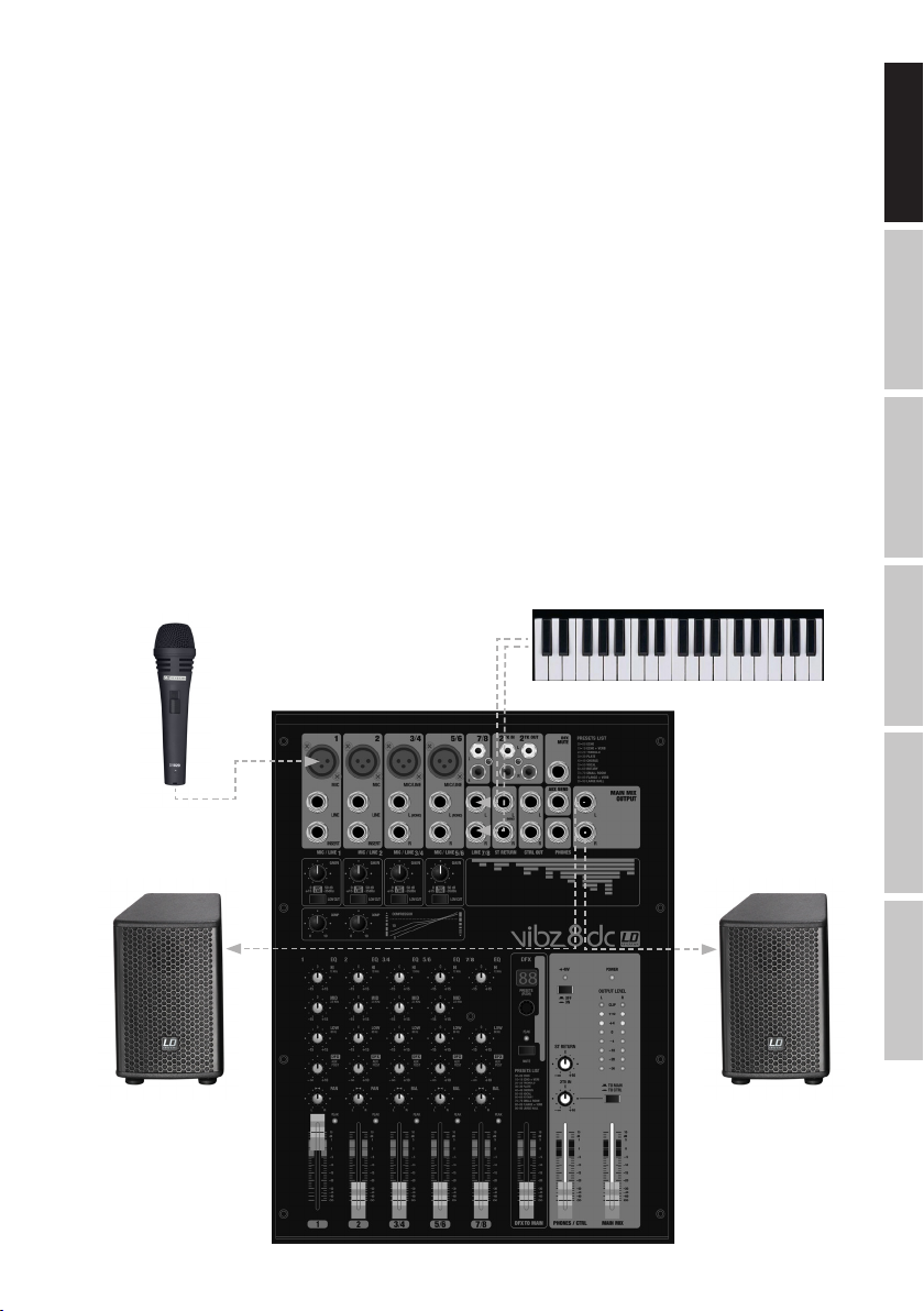
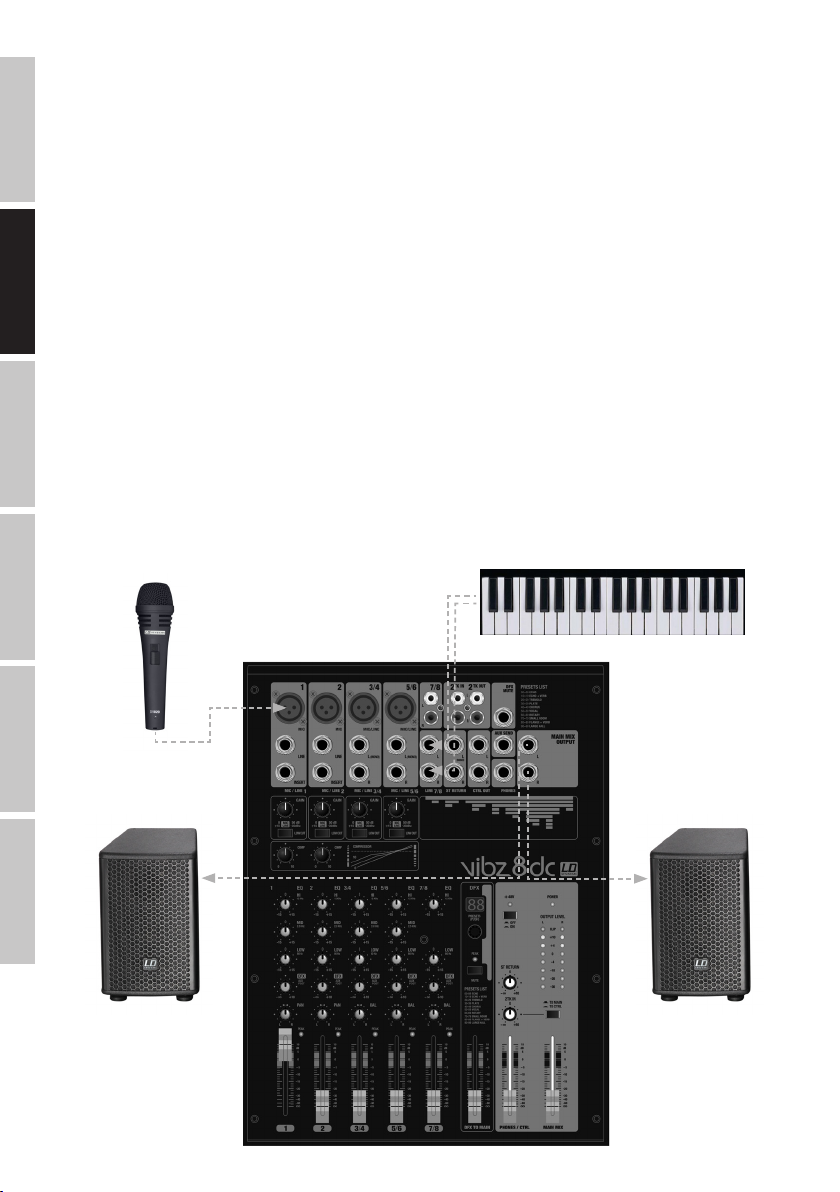
QUICK START GUIDE WITH CABLING EXAMPLE
1. Make sure that the mixer and all devices to be connected to the mixer are turned off.
2. Connect the devices to the mixer using appropriate cables.
3. Adjust the input gain of the channels 1 to 4 and all level controllers channel-LEVEL and MAIN MIX to minimum. Place all equalizer controllers
in the central position (stop). Adjust the volume controller on the active loudspeaker to minimum. Turn on the +48 V phantom power on the
mixer only if you are using a condenser microphone.
4. Turn on the devices in the following order: Microphone and keyboard (or other source devices), then the mixer and lastly the active speakers.
5. Always adjust the gain control of the channels 1 and 2 or 3/4 and 5/6 so that the peak LED of the corresponding channel only lights up
briefly when signal peaks occur. Avoid the permanent lighting of the peak LED by reducing the input gain (Gain).
6 channel 7/8: Adjust the output level of the keyboard (or other source devices) so that the peak LED above the channel only lights up briefly
when signal peaks occur. Avoid the permanent lighting of the peak LED.
7. Bring the level controllers (fader) of the channels in use and of the sum channel MAIN MIX approximately to the 0 dB mark.
8. Now increase the volume of the active speakers for the incoming signal (e.g.speaking, singing, keyboard) to the desired level.
9. Fine-tuning can now be achieved by adjusting the volume ratios of the channels and by using the equalizer, compressors and effects
device as desired.
NOTE: When turning off the devices, please follow these steps: First, set the volume of the active speakers to minimum and turn them off,
then the mixer and connected devices can be switched off.
FRANCAISDEUTSCHENGLISH
Microphone
Active speaker
Electronic keyboard
Active speaker
ITALIANOPOLSKIESPAÑOL
5
Page 6
CONNECTIONS, CONTROLS AND INDICATORS
1
ENGLISH
2
3
4
5
6
DEUTSCHFRANCAIS
7
8
9
10
11
12
14 14 15 23 26
15 28 32
17
16
18
19
20
38 37
22
35
35
25
20
31
39
36
34
24
29
30
13
21 27 33
ESPAÑOL
1
MIC IN CHANNEL 1 - 2 & 3/4 - 5/6
Balanced inputs of the channels 1 and 2, or 3/4 and 5/6 with 3-pin XLR sockets for connecting microphones. Channels 1 and 2 are mono
channels, the channels 3/4 and 5/6 can be used as both mono and stereo channels, depending on the incoming signal (XLR and jack L IN =
Mono / jack L and R IN = Stereo). A 48 V phantom power supply is available for operating condenser microphones, and it can be switched
centrally to the XLR sockets (N° 36). Please set the Gain controller (N 4) to minimum (left stop) before connecting or disconnecting a microphone; and switch on the phantom power only after connecting the microphone, or off before disconnecting.
LINE IN CHANNEL 1 / 2
2
Balanced inputs of the mono channels 1 and 2 with 6.3 mm jack to connect a source device with a line level. Please set the Gain controller
(N 4) to minimum (left stop) before connecting or disconnecting jack cables.
3
INSERT CHANNEL1 / 2
3-pin 6.3 mm jack socket for inserting an external signal processing device (Compressor, Gate, etc.) in the respective mixer channel. A
special insert cable is required for the connection (Y-cable, 1 x stereo jack to 2 x mono jack or XLR). The assignment is as follows: TIP =
ITALIANO POLSKI
Send, RING = Return, SLEEVE = Masse.
4
GAIN CHANNEL 1 / 4
Adjusting the gain of the microphone input from 0 to 50 dB, or the sensitivity of the line input from +15 dBu to -35 dBu. Adjust the Gain
controller so that the peak LED of the corresponding channel only lights up briefly when signal peaks occur. Avoid the permanent lighting of
the peak LED by reducing the input gain or input sensitivity.
5
LOW CUT CHANNEL 1 - 4
Low cut filter for suppressing low-frequency signals. Especially with voice and singing transmissions, an activated LOW CUT feature (switch
in the down position) can reduce disruptive bass frequencies and thus increase speech intelligibility. The cut-off frequency is 95 Hz.
6
Page 7

6
COMPRESSOR
Sliding compressor controller for channels 1 or 2. Depending on the setting, the signal is more or less compressed, i.e., the dynamics of
the signal is restricted (controller to the left stop = compressor is disabled, controller to the right stop = maximum compression). The level
loss caused by the increasingly stronger compression is automatically compensated by the compressor unit. The use of the compressor can
provide for an improved clarity of a singing voice in the mix.
7
EQUALIZER HI CHANNEL 1 - 7/8
Equalizer high band for channels 1 to 7/8 (12 kHz, +/-15 dB). When turned to the left, levels are lowered, when turned to the right, they are
raised. In the centre position (resting point), the equalizer is inactive.
8
EQUALIZER MID CHANNEL 1 - 5/6
Equalizer mid band for channels 1 to 5/6 (2.5 kHz, +/-15 dB). When turned to the left, levels are lowered, when turned to the right, they are
raised. In the centre position (resting point), the equalizer is inactive.
9
EQUALIZER LOW CHANNEL 1 - 7/8
Equalizer bass band for channels 1 to 7/8 (80 kHz, +/-15 dB). When turned to the left, levels are lowered, when turned to the right, they are
raised. In the centre position (resting point), the equalizer is inactive.
10
LEVEL DFX / AUX POST CHANNEL 1 - 7/8
Volume controller for adding the signal from channel 1 to 7/8 to the internal digital effects device (effect send, post fader). Use the Line
Output AUX SEND (N 35) for activating an external effect. When using the AUX SEND jack socket, the internal effects device is automatically
bypassed, and is therefore not usable.
11
PAN CHANNEL 1 / 2 & BAL CHANNEL 3/4 - 7/8
PAN channel 1 and 2: Using the Panorama controller, position the signal of the corresponding channel in the stereo field of the total signal
(Centre position = perception of the signal in the middle of the stereo field). BAL channel 3/4 to 7/8: Use the balance controller to set the
relative volume between the left and right part of the connected stereo signal. When only the XLR socket or left socket L (MONO) of the line
input is in use, the controller performs the function of a Panorama controller.
12
PEAK LED CHANNEL 1 - 7/8
PEAK channel 1 - 5/6: Once the red Peak LED lights up, the corresponding channel is operating at the distortion limit. Adjust the Gain controller
(N 4) so that the peak LED of the corresponding channel only lights up briefly when signal peaks occur. Avoid the permanent lighting of the
peak LED by reducing the input gain or input sensitivity. PEAK Channel 7/8: Once the red Peak LED lights up, the corresponding channel is
operating at the distortion limit. Adjust the output level of the source device so that the peak LED of the corresponding channel only lights up
briefly when signal peaks occur. Avoid the permanent lighting of the peak LED.
FRANCAISDEUTSCHENGLISH
13
FADER CHANNEL 1 - 7/8
Volume controller for channels 1 to 7/8. Press the Fader button upwards to increase the volume of the corresponding channel and downwards
to decrease it.
14
LINE IN L / R CHANNEL 3/4 - 5/6
Unbalanced inputs for the stereo channels 3/4 and 5/6 with 6.3 mm jacks to connect external devices with line level (e.g. keyboard). If only
the left input jack is used (L), the channel will be mono.
15
LINE IN CHANNEL 7/8
Unbalanced line input for the stereo channel 7/8. The RCA sockets can be used as an alternative to the jack sockets of the channel.
16
DFX PRESETS
100 different effects presets are available to you. Use the rotary encoder to select one of the presets as desired (digits in the display N 17
will flash), and then confirm the entry by briefly pressing on the encoder (the flashing of the digits in the display stops).
17
DFX DISPLAY
The four digit LED display shows the number of the selected effect preset.
ITALIANOPOLSKIESPAÑOL
7
Page 8

18
DFX PEAK LED
Once the red Peak LED lights up, the input of the internal effects device is operating at the distortion limit. Adjust the Effect Send controller
of the input channels (N 10) so that the peak LED only lights up briefly when signal peaks occur.
19
DFX MUTE
ENGLISH
In order to mute the internal effects device, briefly press the DFX Mute button once, and again to turn mute off. If Mute is active, the DFX
Peak LED lights up continuously.
20
EFFECTS LIST
List of effects programs for the internal effects device.
21
DFX TO MAIN
DEUTSCHFRANCAIS
Volume controller for adding the effects signal of the internal effects device to the sum channel MAIN MIX. Press the Fader button upwards
to increase the volume of the effect and downwards to decrease it.
22
DFX MUTE FOOTSWITCH
6.3 mm jack socket for connecting a foot switch (pedal) to remotely activate and disable the mute function of the internal effects device
(footswitch optional).
23
ST RETURN L / R
Unbalanced stereo line input with 6.3 mm jack sockets for connecting an external effects device (left input = mono), or another source
device with a line level. Use the AUX SEND jack socket in order to activate an external effects device. When using the AUX SEND jack socket,
the internal effects device is automatically bypassed, and is therefore not usable.
24
ST RETURN
Volume controller for the stereo line input ST RETURN (N 23). The ST RETURN signal is mixed directly into the sum channel MAIN MIX.
Turning the dial to the right increases the volume and turning it to the left decreases it.
ESPAÑOL
25
PHONES
Headphone connection with 6.3 mm stereo jack. Output of the sum channel signal MAIN MIX. The volume can be adjusted via the PHONES /
CTRL volume controller (N 27) and is independent of the volume of the MAIN MIX level controller. Use headphones with a minimum impedance of 30 ohms and make sure that the volume stays at a pleasant level, in order to avoid hearing damage caused by loud noise.
26
CTRL OUT L / R
Unbalanced stereo line output with 6.3 mm jack sockets to connect active monitors etc... Output of the sum channel signal MAIN MIX. The
volume can be adjusted via the PHONES / CTRL volume controller (N 27) and is independent of the volume of the MAIN MIX level controller.
27
PHONES / CTRL
Volume controller for the stereo line output CTRL (N 26) and the headphone output PHONES (N 25). When using headphones, make sure
that the volume stays at a pleasant level, in order to avoid hearing damage caused by loud noise.
28
2 TK IN
Unbalanced stereo line input with RCA sockets for connecting an external audio source with line level (e.g. MP3 player).
ITALIANO POLSKI
29
2 TK IN LEVEL
Volume controller for the stereo line input 2 TK IN (N 28). Turning the dial to the right increases the volume and turning it to the left decreases it.
30
2 TK IN TO MAIN / TO CTRL
This switch allows to route the incoming signal of the stereo line input 2 TK IN either to the stereo line output MAIN MIX OUT (not pressed
down = TO MAIN), or to the stereo line output CTRL OUT and headphone output PHONES (pressed down = TO CTRL).
8
Page 9
31
MAIN MIX OUT
Unbalanced stereo line output with 6.3 mm jack sockets to connect an active PA system. Output of the master signal of the mixer.
32
2 TK OUT
Unbalanced stereo line output with RCA sockets for connecting an external recording device (e.g. laptop). Output of the master signal of the mixer.
33
MAIN MIX
Volume controller for the stereo line outputs MAIN MIX OUT (N 31) and 2 TK OUT (N 32) Press the Fader button upwards to increase the
volume, and downwards to decrease it. Before you turn on the power of the connected PA system, set the volume controller to minimum.
34
OUTPUT LEVEL
8-segment LED level display for visualising the volume level of the stereo sum channel. To avoid distortion, reduce the volume level of the
output channel as soon as the red CLIP LED lights up.
35
AUX SEND
Unbalanced mono line output with 6.3 mm jack sockets to activate an external effects device (POST Fader). When using the AUX SEND jack
socket, the internal effects device is automatically bypassed, and is therefore not usable.
36
+48V ON / OFF
+48 V phantom power supply for operating high-quality condenser microphones without own power supply. Press down to select the ON
position (red LED light is on) to turn on the phantom power for the XLR microphone inputs, and return to the original OFF position to turn
it off (red LED light is off). Turn on the phantom power only after connecting a microphone, or off after disconnecting, and set the volume
controller of the channels 1 to 4 to minimum before this step.
37
AC ADAPTOR IN
Screwable low-voltage socket for the power supply of the mixer. Please use only the supplied AC power supply to avoid damage to the
mixer. Turn on the mixer only after connecting the power supply to the mains and the low-voltage socket. The mains voltage of your power
supplier and the operating voltage of the device must be the same!
FRANCAISDEUTSCHENGLISH
38
POWER ON / OFF
On / Off switch for the power supply of the device.
39
POWER LED
The power LED lights up once the system is properly connected to the power mains and is switched on.
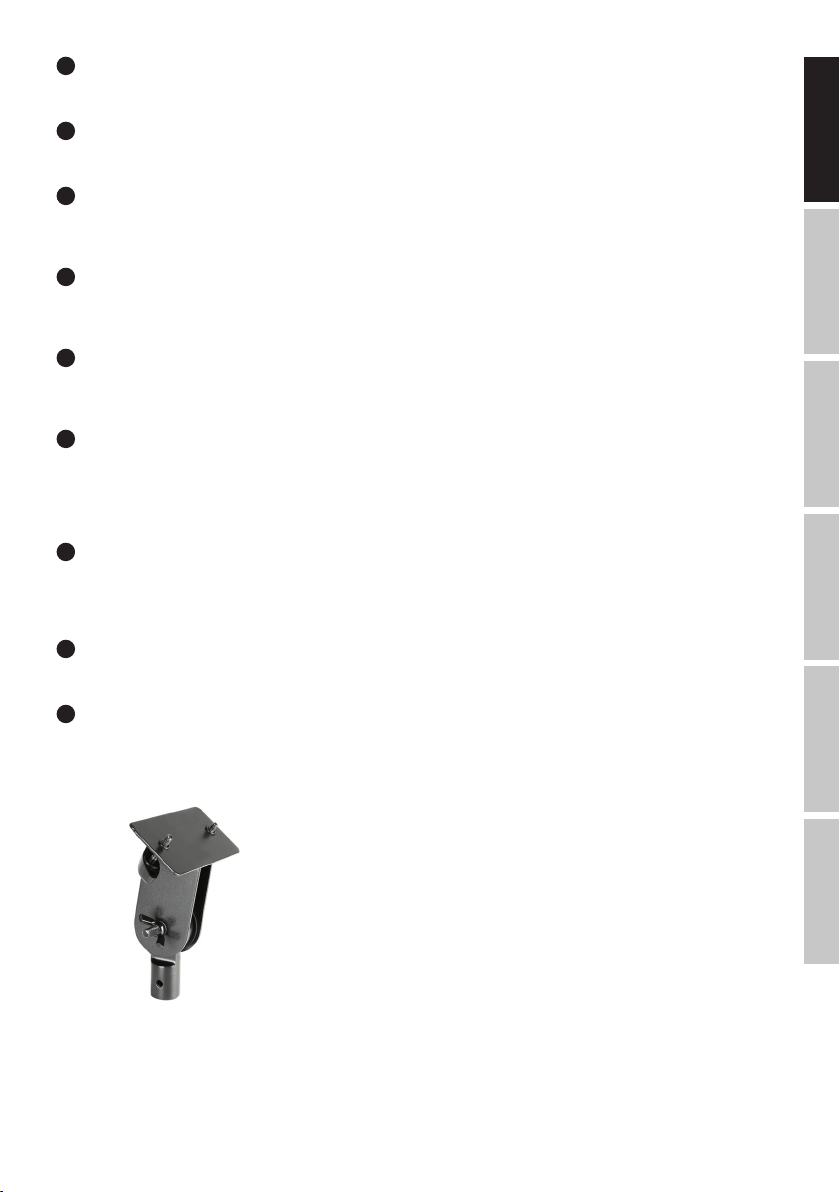
Note: A mounting point for the optional microphone stand adapter LDVIBZMSADAPTOR is located on the underside of the device.
LDVIBZMSADAPTOR
ITALIANOPOLSKIESPAÑOL
9
Page 10

SPECIFICATIONS
Model Name: LDVIBZ8DC
Product Type: analogue mixer
Type: live / home recording
ENGLISH
Number of Channels: 8
Mono Channels:
Mono Mic/Line Input Channels: 4
Mono Mic/Line Input Connections: 6.3 mm stereo jack, XLR
Mono Mic Input Type: electronically balanced, discreet design
Frequency Response Mono Mic Input: 10 - 45,000 Hz
Amplification Range Mono Mic Input: 50 dB
DEUTSCHFRANCAIS
Channel Crosstalk: 62 dB
THD Mono Mic Input: 0.0058%
Impedance Mono Mic Input: 4 kOhm
S/N Ratio Mono Mic Input: 113 dB
Mono Line Input Type: electronically balanced, discreet design
Amplification Range Mono Line Input: 50 dB
THD Mono Line Input: 0.0045%
Impedance Mono Line Input: 21 kOhm
S/N Ratio Mono Line Input: 116 dB
Mono Channel Equalizer Treble: +/-15 dB @ 12 kHz
Mono Channel Equalizer Mids: +/-15 dB @ 2.5 kHz
Mono Channel Equalizer Bass: +/-15 dB @ 80 Hz
Channel Insert: channel 1 & 2
Channel Insert Connections: 6.3 mm stereo jack (TIP= send / RING= return)
Phantom Power: +48 V DC switchable to XLR inputs
ESPAÑOL
Low Cut: 95 Hz
Compressor: channel 1 & 2
Control Elements Channels 1 - 5/6:
Stereo Channels:
Stereo Line Input Channels: 3
Stereo Line Input Connections: 2 x 6.3 mm stereo jack (Lmono, R)
Stereo Line Input Type: unbalanced
Frequency Response Stereo Line Input: 10 - 45,000 Hz
Amplification Range Stereo Line Input: 50 dB
Channel Crosstalk: 62 dB
THD Stereo Line Input: 0.0045%
Impedance Stereo Line Input: 3.7 kOhm
S/N Ratio Stereo Line Input: 116 dB
ITALIANO POLSKI
Stereo Channel Equalizer Treble: +/-15 dB @ 12 kHz
Stereo Channel Equalizer Mids: +/- 15 dB @ 2.5 kHz (not for channel 7/8)
Stereo Channel Equalizer Bass: +/-15 dB @ 80 Hz
Control Elements Channel 7/8: EQ Hi, EQ Low, DFX, Bal, Channel Fader
Main Section:
AUX/Effect Send Channels: 1
AUX/Effect Send Connections: 6.3 mm stereo jack, unbalanced
Stereo AUX Return Channels: 1
Stereo AUX Return Connections: 2 x 6.3 mm stereo jack
Stereo Tape Output Channel: 1 x stereo
Gain, Low Cut, Compressor (channel 1 & 2 only), EQ Hi, EQ Mid, EQ Low, DFX, Pan/Bal,
Channel Fader
10
Page 11
Stereo Tape Output Connections: 2 x RCA (Cinch)
Stereo Tape Input Channel: 1 x stereo
Stereo Tape Input Connections: 2 x RCA (Cinch)
Unbalanced Stereo Main Outputs: 1
Unbalanced Stereo Main Output Connec-
tions:
Impedance Unbalanced Stereo Main
Outputs:
Max. Level Unbalanced Stereo Main
Outputs:
Stereo Control Room Outputs: 1
Stereo Control Room Output Connections: 2 x 6.3 mm jack
Headphone Output: 1
Headphone Output Connections: 6.3 mm stereo jack
Minimum Headphone Impedance: 30 ohms
Digital Effects Processor: yes
No. of Presets: 100
Foot Switch Connection DFX Mute: 6.3 mm jack (foot switch optional)
Control Elements Main Section:
Specifications:
Display Elements:
Power Supply: 18 V AC - 1 A, External PSU (included)
Temperature Range For Operation: 0°C to +45°C
Humidity Range For Operation: 10%rel - 80%rel
Width: 265 mm
Height: 77 mm
Depth: 350 mm
Weight: 2.3 kg
Other Features: microphone stand adapter optional (LDVIBZMSADAPTOR)
6.3 mm stereo jack, unbalanced
120 ohms
20 dBV
DFX Presets, DFX Mute, DFX to Main Fader, ST Return, 2 TK In, 2 TK In To Main/To CTRL,
Phones/CTRL Fader, Phantom Power +48V, Main Mix Fader, Power
Channel Peak, Effects Peak, DFX LED Display, Power, Phantom Power, 2 x 8-segment level
display
FRANCAISDEUTSCHENGLISH
MANUFACTURER´S DECLARATIONS
MANUFACTURER‘S WARRANTY & LIMITATIONS OF LIABILITY
You can find our current warranty conditions and limitations of liability at: http://www.adamhall.com/media/shop/downloads/documents/
manufacturersdeclarations.pdf. To request warranty service for a product, please contact Adam Hall GmbH, Daimler Straße 9, 61267 Neu
Anspach / Email: Info@adamhall.com / +49 (0)6081 / 9419-0.
CORRECT DISPOSAL OF THIS PRODUCT
(valid in the European Union and other European countries with a differentiated waste collection system)
This symbol on the product, or on its documents indicates that the device may not be treated as household waste. This is to avoid
environmental damage or personal injury due to uncontrolled waste disposal. Please dispose of this product separately from other waste
and have it recycled to promote sustainable economic activity. Household users should contact either the retailer where they purchased
this product, or their local government office, for details on where and how they can recycle this item in an environmentally friendly manner.
Business users should contact their supplier and check the terms and conditions of the purchase contract. This product should not be mixed
with other commercial waste for disposal.
ITALIANOPOLSKIESPAÑOL
11
Page 12

DEUTSCH
SIE HABEN DIE RICHTIGE WAHL GETROFFEN!
Dieses Gerät wurde unter hohen Qualitätsanforderungen entwickelt und gefertigt, um viele Jahre einen reibungslosen Betrieb zu gewährleisten. Dafür steht LD Systems mit seinem Namen und der langjährigen Erfahrung als Hersteller hochwertiger Audioprodukte. Bitte lesen
Sie diese Bedienungsanleitung sorgfältig, damit Sie Ihr neues Produkt von LD Systems schnell optimal einsetzen können.
ENGLISH
Mehr Informationen zu LD SYSTEMS finden Sie auf unserer Internetseite WWW.LD-SYSTEMS.COM
SICHERHEITSHINWEISE
1. Lesen Sie diese Anleitung bitte sorgfältig durch.
2. Bewahren Sie alle Informationen und Anleitungen an einem sicheren Ort auf.
3. Befolgen Sie die Anweisungen.
4. Beachten Sie alle Warnhinweise. Entfernen Sie keine Sicherheitshinweise oder andere Informationen vom Gerät.
5. Verwenden Sie das Gerät nur in der vorgesehenen Art und Weise.
6. Verwenden Sie ausschließlich stabile und passende Stative bzw. Befestigungen (bei Festinstallationen). Stellen Sie sicher, dass Wandhalterungen ordnungsgemäß installiert und gesichert sind. Stellen Sie sicher, dass das Gerät sicher installiert ist und nicht herunterfallen kann.
DEUTSCHFRANCAIS
7. Beachten Sie bei der Installation die für Ihr Land geltenden Sicherheitsvorschriften.
8. Installieren und betreiben Sie das Gerät nicht in der Nähe von Heizkörpern, Wärmespeichern, Öfen oder sonstigen Wärmequellen. Sorgen
Sie dafür, dass das Gerät immer so installiert ist, dass es ausreichend gekühlt wird und nicht überhitzen kann.
9. Platzieren Sie keine Zündquellen wie z.B. brennende Kerzen auf dem Gerät.
10. Lüftungsschlitze dürfen nicht blockiert werden.
11. Betreiben Sie das Gerät nicht in unmittelbarer Nähe von Wasser. Bringen Sie das Gerät nicht mit brennbaren Materialien, Flüssigkeiten
oder Gasen in Berührung. Direkte Sonneneinstrahlung vermeiden!
12. Sorgen Sie dafür, dass kein Tropf- oder Spritzwasser in das Gerät eindringen kann. Stellen Sie keine mit Flüssigkeit gefüllten Behältnisse
wie Vasen oder Trinkgefäße auf das Gerät.
13. Sorgen Sie dafür, dass keine Gegenstände in das Gerät fallen können.
14. Betreiben Sie das Gerät nur mit dem vom Hersteller empfohlenen und vorgesehenen Zubehör.
15. Öffnen Sie das Gerät nicht und verändern Sie es nicht.
16. Überprüfen Sie nach dem Anschluss des Geräts alle Kabelwege, um Schäden oder Unfälle, z. B. durch Stolperfallen zu vermeiden.
17. Achten Sie beim Transport darauf, dass das Gerät nicht herunterfallen und dabei möglicherweise Sach- und Personenschäden verursachen kann.
18. Wenn Ihr Gerät nicht mehr ordnungsgemäß funktioniert, Flüssigkeiten oder Gegenstände in das Geräteinnere gelangt sind, oder das
Gerät anderweitig beschädigt wurde, schalten Sie es sofort aus und trennen es von der Netzsteckdose (sofern es sich um ein aktives Gerät
handelt). Dieses Gerät darf nur von autorisiertem Fachpersonal repariert werden.
19. Verwenden Sie zur Reinigung des Geräts ein trockenes Tuch.
20. Beachten Sie alle in Ihrem Land geltenden Entsorgungsgesetze. Trennen Sie bei der Entsorgung der Verpackung bitte Kunststoff und
ESPAÑOL
Papier bzw. Kartonagen voneinander.
21. Kunststoffbeutel müssen außer Reichweite von Kindern aufbewahrt werden.
BEI GERÄTEN MIT NETZANSCHLUSS
22. ACHTUNG: Wenn das Netzkabel des Geräts mit einem Schutzkontakt ausgestattet ist, muss es an einer Steckdose mit Schutzleiter
angeschlossen werden. Deaktivieren Sie niemals den Schutzleiter eines Netzkabels.
23. Schalten Sie das Gerät nicht sofort ein, wenn es starken Temperaturschwankungen ausgesetzt war (beispielsweise nach dem Transport).
Feuchtigkeit und Kondensat könnten das Gerät beschädigen. Schalten Sie das Gerät erst ein, wenn es Zimmertemperatur erreicht hat.
24. Bevor Sie das Gerät an die Steckdose anschließen, prüfen Sie zuerst, ob die Spannung und die Frequenz des Stromnetzes mit den auf
dem Gerät angegebenen Werten übereinstimmen. Verfügt das Gerät über einen Spannungswahlschalter, schließen Sie das Gerät nur an die
Steckdose an, wenn die Gerätewerte mit den Werten des Stromnetzes übereinstimmen. Wenn das mitgelieferte Netzkabel bzw. der mitgelieferte Netzadapter nicht in Ihre Netzsteckdose passt, wenden Sie sich an Ihren Elektriker.
25. Treten Sie nicht auf das Netzkabel. Sorgen Sie dafür, dass spannungsführende Kabel speziell an der Netzbuchse bzw. am Netzadapter
und der Gerätebuchse nicht geknickt werden.
26. Achten Sie bei der Verkabelung des Geräts immer darauf, dass das Netzkabel bzw. der Netzadapter stets frei zugänglich ist. Trennen Sie
das Gerät stets von der Stromzuführung, wenn das Gerät nicht benutzt wird, oder Sie das Gerät reinigen möchten. Ziehen Sie Netzkabel und
Netzadapter immer am Stecker bzw. am Adapter und nicht am Kabel aus der Steckdose. Berühren Sie Netzkabel und Netzadapter niemals mit
nassen Händen.
27. Schalten Sie das Gerät möglichst nicht schnell hintereinander ein und aus, da sonst die Lebensdauer des Geräts beeinträchtigt werden könnte.
ITALIANO POLSKI
28. WICHTIGER HINWEIS: Ersetzen Sie Sicherungen ausschließlich durch Sicherungen des gleichen Typs und Wertes. Sollte eine Sicherung
wiederholt auslösen, wenden Sie sich bitte an ein autorisiertes Servicezentrum.
29. Um das Gerät vollständig vom Stromnetz zu trennen, entfernen Sie das Netzkabel bzw. den Netzadapter aus der Steckdose.
30. Wenn Ihr Gerät mit einem verriegelbaren Netzanschluss bestückt ist, muss der passende Gerätestecker entsperrt werden, bevor er entfernt werden kann. Das bedeutet aber auch, dass das Gerät durch ein Ziehen am Netzkabel verrutschen und herunterfallen kann, wodurch
Personen verletzt werden und/oder andere Schäden auftreten können. Verlegen Sie Ihre Kabel daher immer sorgfältig.
31. Entfernen Sie Netzkabel und Netzadapter aus der Steckdose bei Gefahr eines Blitzschlags oder wenn Sie das Gerät länger nicht verwenden.
ACHTUNG
Entfernen Sie niemals die Abdeckung, da sonst das Risiko eines elektrischen Schlages besteht. Im
Inneren des Geräts befinden sich keine Teile, die vom Bediener repariert oder gewartet werden können.
Lassen Sie Wartung und Reparaturen ausschließlich von qualifiziertem Servicepersonal durchführen.
12
Page 13

Das gleichseitige Dreieck mit Blitzsymbol warnt vor nichtisolierten, gefährlichen Spannungen im Geräteinneren, die einen elektrischen
Schlag verursachen können.
Das gleichseitige Dreieck mit Ausrufungszeichen kennzeichnet wichtige Bedienungs- und Wartungshinweise.
Warnung! Dieses Symbol kennzeichnet heiße Oberflächen. Während des Betriebs können bestimmte Teile des Gehäuses heiß werden.
Berühren oder transportieren Sie das Gerät nach einem Einsatz erst nach einer Abkühlzeit von mindestens 10 Minuten.
ACHTUNG HOHE LAUTSTÄRKEN BEI AUDIOPRODUKTEN!
Dieses Gerät ist für den professionellen Einsatz vorgesehen. Der kommerzielle Betrieb dieses Geräts unterliegt den jeweils gültigen nationalen
Vorschriften und Richtlinien zur Unfallverhütung. Als Hersteller ist Adam Hall gesetzlich verpflichtet, Sie ausdrücklich auf mögliche Gesundheitsrisiken hinzuweisen. Gehörschäden durch hohe Lautstärken und Dauerbelastung: Bei der Verwendung dieses Produkts können hohe Schalldruckpegel
(SPL) erzeugt werden, die bei Künstlern, Mitarbeitern und Zuschauern zu irreparablen Gehörschäden führen können. Vermeiden Sie länger
anhaltende Belastung durch hohe Lautstärken über 90 dB.
EINFÜHRUNG
LDVIBZ8DC - 8-Kanal Mixer mit digitaler Effektsektion und Compressor
Vier symmetrierte Mikrofoneingänge mit hochwertigen Vorverstärkern, monokompatible Stereokanäle, ein integrierter Compressor und 100
digitale Effekte mit 24-Bit Auflösung machen den VIBZ 8 DC zur flexiblen Sound-Zentrale.
Die auf Line-Pegel umschaltbaren Mikrofonkanäle sind mit hochwertigen Vorverstärkern und einer Bassabsenkung ausgestattet, zwei davon
zudem mit Inserts zur individuellen Signalbearbeitung. Für eine präzise Klangregelung besitzt der VIBZ 8 DC effektive 3-Band-EQs mit
praxisgerecht gewählten Mittenfrequenzen. Die Mastersektion des Mixers verfügt über einen Effektweg, regelbare Monitorausgänge und
einem Kopfhöreranschluß. Der VIBZ 8 DC besitzt zudem Ein- und Ausgänge für Aufnahme- und Abspielgeräte, ist äußerst einfach zu bedienen und
besticht mit seinem transparenten und detaillierten Klang. Er ist ideal für kleine Bands, Installationen, Homerecording und zum Einsatz als Submixer.
FRANCAISDEUTSCHENGLISH
ITALIANOPOLSKIESPAÑOL
13
Page 14
SCHNELLSTARTANLEITUNG MIT VERKABELUNGSBEISPIEL
1. Achten Sie darauf, dass das Mischpult und alle Geräte, die am Mischpult angeschlossen werden sollen, ausgeschaltet sind.
2. Schließen Sie die Geräte mit geeigneten Kabeln am Mischpult an.
ENGLISH
3. Stellen Sie die Vorverstärkung der Kanäle 1 bis 4 und alle Pegelsteller Kanal-LEVEL und MAIN MIX auf Minimum. Bringen Sie die Regler
aller Equalizer in Mittelstellung (Rastpunkt). Stellen Sie die Lautstärkeregler der aktiven Lautsprecher auf Minimum. Schalten Sie die +48V
Phantomspeisung des Mischpults nur ein, wenn Sie ein Kondensatormikrofon verwenden.
4. Schalten Sie die Geräte in der folgenden Reihenfolge ein: Mikrofon und Keyboard (oder andere Zuspielgeräte), das Mischpult und zuletzt
die aktiven Lautsprecher.
5. Stellen Sie die Gain-Regler der Kanäle 1 und 2, bzw. 3/4 und 5/6 so ein, dass die Peak-LED des entsprechenden Kanals nur bei Pegelspitzen des
anliegenden Signals kurz aufleuchtet. Vermeiden Sie permanentes Leuchten der Peak-LED durch Reduzieren der Eingangsvorverstärkung (Gain).
DEUTSCHFRANCAIS
6. Kanal 7/8: Stellen Sie den Ausgangspegel des Keyboards (oder andere Zuspielgeräte) so ein, dass die Peak-LED des Kanals nur bei
Pegelspitzen des anliegenden Signals kurz aufleuchtet. Vermeiden Sie permanentes Leuchten der Peak-LED.
7. Bringen Sie die Pegelsteller (Fader) der verwendeten Kanäle und des Summenkanals MAIN MIX ungefähr auf die 0 dB Markierung.
8. Erhöhen Sie bei anliegendem Signal (z.B. Sprache, Gesang, Keyboard) nun die Lautstärke der aktiven Lautsprecher auf den gewünschten Pegel.
9. Die Feinabstimmung durch das Einstellen der Lautstärkenverhältnisse der Kanäle und die Verwendung der Equalizer, Compressoren und
des Effektgeräts kann nun nach Wunsch durchgeführt werden.
HINWEIS: Beim Ausschalten der Geräte beachten Sie bitte folgende Schritte: Stellen Sie zuerst die Lautstärke der aktiven Lautsprecher auf
Minimum und schalten Sie aus, danach können das Mischpult und die angeschlossenen Geräte ausgeschaltet werden.
ESPAÑOL
ITALIANO POLSKI
Mikrofon
Aktivlautsprecher
elektronisches Keyboard
Aktivlautsprecher
14
Page 15

ANSCHLÜSSE, BEDIEN- UND ANZEIGEELEMENTE
1
2
3
4
5
6
14 14 15 23 26
15 28 32
22
35
35
25
20
31
38 37
7
8
9
10
11
12
13
1
MIC IN KANAL 1 - 2 & 3/4 - 5/6
17
16
18
19
24
20
29
21 27 33
39
36
34
30
Symmetrische Eingänge der Kanäle 1 und 2, bzw. 3/4 und 5/6 mit 3-Pol XLR-Buchsen zum Anschließen von Mikrofonen. Die Kanäle 1 und 2
sind Mono-Kanäle, die Kanäle 3/4 und 5/6 können je nach Belegung sowohl als Mono- als auch als Stereo-Kanäle verwendet werden (XLR
und Klinke L IN = Mono / Klinke L und R IN = Stereo) . Für den Betrieb von Kondensator-Mikrofonen steht eine 48V Phantomspeisung zur
Verfügung, die zentral auf die XLR-Buchsen zugeschaltet werden kann (Nr. 36). Vor dem Ein- bzw. Ausstecken von Mikrofonen stellen Sie den
Gain-Regler (Nr. 4) bitte auf ein Minimum (Linksanschlag) und schalten die Phantomspeisung erst nach dem Anschließen eines Mikrofons ein,
bzw. vor dem Ausstecken aus.
LINE IN KANAL 1 / 2
2
Symmetrische Eingänge der Mono-Kanäle 1 und 2 mit 6,3mm Klinkenbuchse zum Anschließen eines Zuspielgeräts mit Line-Pegel. Vor dem
Ein- bzw. Ausstecken von Klinkenkabeln stellen Sie den Gain-Regler (Nr. 4) bitte auf ein Minimum (Linksanschlag).
3
INSERT KANAL1 / 2
3-polige 6,3mm Klinkenbuchse zum Einschleifen eines externen signalverarbeitenden Geräts (Compressor, Gate usw.) in den entsprechenden
Mischpult-Kanal. Für die Verbindung wird ein spezielles Insert-Kabel benötigt (Y-Kabel, 1x Stereo-Klinke auf 2x Mono-Klinke, bzw. XLR). Die
Belegung der Buchse ist wie folgt: TIP = Send, RING = Return, SLEEVE = Masse.
FRANCAISDEUTSCHENGLISH
ITALIANOPOLSKIESPAÑOL
4
GAIN KANAL 1 / 4
Justieren der Vorverstärkung des Mikrofon-Eingangs von 0 bis 50 dB, bzw. der Empfindlichkeit des Line-Eingangs von +15 bis -35 dBu. Stellen
Sie den Gain-Regler so ein, dass die Peak-LED des entsprechenden Kanals nur bei Pegelspitzen des anliegenden Signals kurz aufleuchtet.
Vermeiden Sie permanentes Leuchten der Peak-LED durch Reduzierung der Eingangsvorverstärkung, bzw. der Eingangsempfindlichkeit.
15
Page 16

5
LOW CUT KANAL 1 - 4
Tiefensperre für die Unterdrückung tieffrequenter Signalanteile. Vor allem bei Sprach- und Gesangsübertragung kann ein aktivierter LOW CUT
(Schalter in heruntergedrückter Position) störende Bassfrequenzen absenken und somit die Textverständlichkeit steigern. Die Grenzfrequenz
liegt bei 95 Hz.
ENGLISH
6
COMPRESSOR
Stufenlos regelbarer Compressor für die Kanäle 1, bzw. 2. Je nach Einstellung wird das anliegende Signal weniger, oder stärker verdichtet,
d.h., die Dynamik des Signals wird eingeschränkt (Linksanschlag des Reglers = Compressor deaktiviert, Rechtsanschlag = maximale
Verdichtung). Der durch zunehmend stärkerer Verdichtung größer werdende Pegelverlust wird von der Compressor-Einheit automatisch
ausgeglichen. Der Einsatz des Compressors kann z.B. für eine verbesserte Durchsetzung einer Gesangsstimme im Mix sorgen.
7
EQUALIZER HI KANAL 1 - 7/8
Equalizer Höhenband für die Kanäle 1 bis 7/8 (12 kHz, +/-15 dB). Nach links gedreht werden Höhen abgesenkt, nach rechts gedreht angehoben.
DEUTSCHFRANCAIS
In Mittelstellung (Rastpunkt) ist der Equalizer inaktiv.
8
EQUALIZER MID KANAL 1 - 5/6
Equalizer Mittenband für die Kanäle 1 bis 5/6 (2,5 kHz, +/-15 dB). Nach links gedreht werden Mitten abgesenkt, nach rechts gedreht angehoben. In
Mittelstellung (Rastpunkt) ist der Equalizer inaktiv.
9
EQUALIZER LOW KANAL 1 - 7/8
Equalizer Bassband für die Kanäle 1 bis 7/8 (80 Hz, +/-15 dB). Nach links gedreht werden Bässe abgesenkt, nach rechts gedreht angehoben. In
Mittelstellung (Rastpunkt) ist der Equalizer inaktiv.
10
LEVEL DFX / AUX POST KANAL 1 - 7/8
Pegelsteller für die Zumischung des Signals von Kanal 1 bis 7/8 auf das interne digitale Effektgerät (Effekt Send, Post Fader). Verwenden Sie
den Line-Ausgang AUX SEND (Nr. 35) zur Ansteuerung eines externen Effektgeräts. Bei der Verwendung der AUX SEND-Klinkenbuchse, wird
das interne Effektgerät automatisch umgangen und ist somit nicht verwendbar.
11
ESPAÑOL
PAN CHANNEL 1 / 2 & BAL KANAL 3/4 - 7/8
PAN Kanal 1 und 2: Mit Hilfe des Panorama-Reglers positionieren Sie das Signal des entsprechenden Kanals im Stereofeld des Gesamtsignals
(Mittelstellung = Wahrnehmung des Signals in der Mitte des Stereofelds). BAL Kanal 3/4 bis 7/8: Mit Hilfe des Balance-Reglers stellen Sie das
Lautstärkenverhältnis zwischen dem linken und rechten Anteil des anliegenden Stereo-Signals ein. Sobald die XLR-Buchse, bzw. lediglich
die linke Buchse L (MONO) des Line-Eingangs belegt ist, erfüllt der Regler die Funktion eines Panorama-Reglers.
12
PEAK LED KANAL 1 - 7/8
PEAK Kanal 1 - 5/6: Sobald die rote Peak-LED aufleuchtet, wird der Eingang des entsprechenden Kanals an der Verzerrungsgrenze betrieben.
Stellen Sie den Gain-Regler (Nr. 4) so ein, dass die Peak-LED nur bei Pegelspitzen des anliegenden Signals kurz aufleuchtet. Vermeiden Sie
permanentes Leuchten der Peak-LED durch Reduzierung der Eingangsvorverstärkung, bzw. der Eingangsempfindlichkeit. PEAK Kanal 7/8:
Sobald die rote Peak-LED aufleuchtet, wird der Eingang des entsprechenden Kanals an der Verzerrungsgrenze betrieben. Stellen Sie den
Ausgangspegel des Zuspielgeräts so ein, dass die Peak-LED nur bei Pegelspitzen des anliegenden Signals kurz aufleuchtet. Vermeiden Sie
permanentes Leuchten der Peak-LED.
13
FADER KANAL 1 - 7/8
Pegelsteller für die Kanäle 1 bis 7/8. Schieben Sie den Fader-Knopf nach oben, um die Lautstärke des entsprechenden Kanals anzuheben
und nach unten, um sie zu verringern.
ITALIANO POLSKI
14
LINE IN L / R KANAL 3/4 - 5/6
Unsymmetrische Eingänge der Stereo-Kanäle 3/4 und 5/6 mit 6,3mm Klinken-Buchsen zum Anschließen von Zuspielgeräten mit Line-Pegel
(z.B. Keyboard). Wird lediglich die Eingangsbuchse links (L) belegt, wird der Kanal Mono betrieben.
15
LINE IN KANAL 7/8
Unsymmetrischer Line-Eingang des Stereo Kanals 7/8. Die Cinch-Buchsen können alternativ zu den Klinken-Buchsen des Kanals verwendet werden.
16
Page 17

16
DFX PRESETS
100 verschiedene Effekt-Presets stehen Ihnen zur Verfügung. Verwenden Sie den Drehgeber, um wunschgemäß eines der Presets
auszuwählen (Ziffern im Display Nr. 17 blinken) und bestätigen dann die Eingabe durch kurzes Drücken auf den Drehgeber (das Blinken der
Ziffern im Display stoppt).
17
DFX DISPLAY
Das 2-stellige LED-Display zeigt die Nummer des ausgewählten Effekt-Presets an.
18
DFX PEAK LED
Sobald die rote Peak-LED aufleuchtet, wird der Eingang des internen Effektgeräts an der Verzerrungsgrenze betrieben. Stellen Sie die
Effekt-Send-Pegelsteller der Eingangskanäle (Nr. 10) so ein, dass die Peak-LED nur bei Pegelspitzen des anliegenden Signals kurz aufleuchtet.
19
DFX MUTE
Um das interne Effektgerät stummzuschalten, drücken Sie kurz auf den DFX Mute-Taster und nochmals, um die Stummschaltung zu
deaktivieren. Ist die Stummschaltung aktiv, leuchtet die DFX Peak-LED permanent.
20
EFFEKTLISTE
Liste der Effektprogramme des internen Effektgeräts.
21
DFX TO MAIN
Pegelsteller für die Zumischung des Effekt-Signals des internen Effektgeräts auf den Summenkanal MAIN MIX. Schieben Sie den Fader-Knopf
nach oben, um die Effekt-Lautstärke anzuheben und nach unten, um sie zu verringern.
22
DFX MUTE FOOTSWITCH
6,3mm Klinkenbuchse zum Anschließen eines Fußtasters (Schließer) um die Stummschaltung des internen Effektgeräts ferngesteuert zu
aktivieren und deaktivieren (Fußtaster optional).
23
ST RETURN L / R
Unsymmetrischer Stereo-Line-Eingang mit 6,3mm Klinkenbuchsen für den Anschluss eines externen Effektgeräts (Eingang links = Mono),
oder eines anderen Zuspielgeräts mit Line-Pegel. Verwenden Sie die AUX SEND-Klinkenbuchse, um ein externes Effektgerät anzusteuern.
Bei der Verwendung der AUX SEND-Klinkenbuchse, wird das interne Effektgerät automatisch umgangen und ist somit nicht verwendbar.
24
ST RETURN
Pegelsteller für den Stereo-Line-Eingang ST RETURN (Nr. 23). Das ST RETURN-Signal wird direkt auf den Summenkanal MAIN MIX gemischt.
Nach links gedreht verringert sich, nach rechts gedreht erhöht sich die Lautstärke.
25
PHONES
Kopfhöreranschluss mit 6,3mm Stereo-Klinkenbuchse. Ausgabe des Signals des Summenkanals MAIN MIX. Die Lautstärkeneinstellung
erfolgt über den Pegelsteller PHONES / CTRL (Nr. 27) und ist unabhängig von der Lautstärkeneinstellung des Pegelstellers MAIN MIX.
Verwenden Sie Kopfhörer mit einer minimalen Impedanz von 30 Ohm und achten darauf, die Lautstärke auf einem angenehmen Pegel zu
halten, um Gehörschäden durch laute Geräusche zu vermeiden.
26
CTRL OUT L / R
Unsymmetrischer Stereo-Line-Ausgang mit 6,3mm Klinkenbuchsen zum Anschließen von aktiven Monitoren etc.. Ausgabe des Signals des
Summenkanals MAIN MIX. Die Lautstärkeneinstellung erfolgt über den Pegelsteller PHONES / CTRL (Nr. 27) und ist unabhängig von der
Lautstärkeneinstellung des Pegelstellers MAIN MIX.
FRANCAISDEUTSCHENGLISH
ITALIANOPOLSKIESPAÑOL
27
PHONES / CTRL
Pegelsteller für den Stereo-Line-Ausgang CTRL (Nr. 26) und den Kopfhörer-Ausgang PHONES (Nr. 25). Besonders bei der Verwendung
von Kopfhörern, achten Sie darauf, die Lautstärke auf einem angenehmen Pegel zu halten, um Gehörschäden durch laute Geräusche zu
vermeiden.
28
2 TK IN
Unsymmetrischer Stereo-Line-Eingang mit Cinch-Buchsen zum Anschließen eines Zuspielgeräts mit Line-Pegel (z.B. MP3-Player).
17
Page 18

29
2 TK IN LEVEL
Pegelsteller für den Stereo-Line-Eingang 2 TK IN (Nr. 28). Nach links gedreht verringert sich, nach rechts gedreht erhöht sich die Lautstärke.
30
2 TK IN TO MAIN / TO CTRL
Dieser Umschalter ermöglicht es, das am Stereo-Line-Eingang 2TK IN anliegende Signal wahlweise auf die Stereo-Line-Ausgänge MAIN MIX OUT,
ENGLISH
CTRL OUT und den Kopfhörerausgang PHONES (nicht heruntergedrückte Position TO MAIN), oder ausschließlich auf den Stereo-Line-Ausgang CTRL
OUT und den Kopfhörerausgang PHONES zu routen (heruntergedrückte Position TO CTRL).
31
MAIN MIX OUT
Unsymmetrischer Stereo-Line-Ausgang mit 6,3mm Klinkenbuchsen zum Anschließen einer aktiven Beschallungsanlage. Ausgabe des
Summen-Signals des Mischpults.
32
2 TK OUT
DEUTSCHFRANCAIS
Unsymmetrischer Stereo-Line-Ausgang mit Cinch-Buchsen zum Anschließen eines Aufnahmegeräts (z.B. Laptop). Ausgabe des Summen-Signals
des Mischpults.
33
MAIN MIX
Pegelsteller für die Stereo-Line-Ausgänge MAIN MIX OUT (Nr. 31) und 2 TK OUT (Nr. 32). Schieben Sie den Fader-Knopf nach oben, um die
Lautstärke anzuheben und nach unten, um sie zu verringern. Stellen Sie vor dem Einschalten der angeschlossenen Beschallungsanlage den
Pegelsteller auf Minimum.
34
OUTPUT LEVEL
8-Segment LED-Pegel-Anzeige für die Visualisierung des Pegels im Stereo-Summenkanal. Um Verzerrungen zu vermeiden, reduzieren Sie
den Ausgangspegel, sobald die rote CLIP-LED aufleuchtet.
35
AUX SEND
Unsymmetrischer Mono-Line-Ausgang mit 6,3mm Klinkenbuchse zum Ansteuern eines externen Effektgeräts (POST Fader). Bei der Verwendung
der AUX SEND-Klinkenbuchse, wird das interne Effektgerät automatisch umgangen und ist somit nicht verwendbar.
ESPAÑOL
36
+48V ON / OFF
+48V Phantomspeisung für den Betrieb von Kondensatormikrofonen ohne eigene Spannungsversorgung. Bringen Sie den Schalter in die
heruntergedrückte Position ON (rote Anzeige-LED leuchtet), um die Phantomspeisung für die XLR Mikrofon-Eingänge einzuschalten und in
die nicht heruntergedrückte Position OFF, um sie auszuschalten (rote Anzeige-LED erlischt). Schalten Sie die Phantomspeisung erst nach
dem Anschließen eines Mikrofons ein, bzw. vor dem Ausstecken aus und stellen vor einem Schaltvorgang die Pegelsteller der Kanäle 1 bis
4 auf Minimum.
37
AC ADAPTOR IN
Verschraubbare Kleinspannungsbuchse für die Spannungsversorgung des Mischpults. Verwenden Sie bitte aussschließlich das mitgelieferte
AC-Netzteil, um Schäden am Mischpult zu vermeiden. Schalten Sie das Mischpult erst nach dem Anschließen des Netzteils am Stromnetz und
der Kleinspannungsbuchse ein. Die Netzspannung Ihres Energieversorgers und die Primärspannung des Netzteils müssen übereinstimmen!
38
POWER ON / OFF
Ein- / Ausschalter für die Spannungszufuhr des Mischpults.
ITALIANO POLSKI
39
POWER LED
Die Power-LED leuchtet, sobald das Gerät korrekt am Stromnetz angeschlossen und eingeschaltet ist.
18
Page 19

Hinweis: Auf der Geräteunterseite befindet sich ein Montagepunkt für den optionalen Mikrofonstativ-Adapter LDVIBZMSADAPTOR.
LDVIBZMSADAPTOR
TECHNISCHE DATEN
Modellbezeichnung: LDVIBZ8DC
Produktart: Analoges Mischpult
Typ: Live / Home recording
Anzahl Kanäle: 8
Mono Kanäle:
Mono Mic/Line Eingangskanäle: 4
Mono Mic/Line Eingangsanschlüsse: 6,3 mm Stereoklinke, XLR
Mono Mic Eingangstyp: elektronisch symmetriert, diskreter Aufbau
Frequenzgang Mono Mic Eingang: 10 - 45.000Hz
Verstärkungsbereich Mono Mic Eingang: 50dB
Kanalübersprechung: 62 dB
THD Mono Mic Eingang: 0.0058%
Impedanz Mono Mic Eingang: 4kOhm
S/N Ratio Mono Mic Eingang: 113dB
Mono Line Eingangstyp: elektronisch symmetriert, diskreter Aufbau
Verstärkungsbereich Mono Line Eingang: 50dB
THD Mono Line Eingang: 0.0045%
Impedanz Mono Line Eingang: 21k Ohm
S/N Ratio Mono Line Eingang: 116dB
Mono Kanal Equalizer Höhen: +/- 15dB @ 12kHz
Mono Kanal Equalizer Mitten: +/- 15dB @ 2,5kHz
Mono Kanal Equalizer Bässe: +/- 15dB @ 80Hz
Kanal-Insert: Kanal 1 & 2
Kanal-Insert Anschlüsse: 6,3 mm Stereoklinke (TIP= send / RING= return)
Phantomspeisung: +48V DC schaltbar auf XLR Inputs
Low Cut: 95Hz
Compressor: Kanal 1 & 2
Bedienelemente Kanal 1 - 5/6:
Stereo Kanäle:
Stereo Line Eingangskanäle: 3
Stereo Line Eingangsanschlüsse: 2x 6,3 mm Stereoklinke (Lmono, R)
Stereo Line Eingangstyp: Unbalanced
Gain, Low Cut, Compressor (nur Kanal 1 & 2), EQ Hi, EQ Mid, EQ Low, DFX, Pan/Bal,
Kanal-Fader
FRANCAISDEUTSCHENGLISH
ITALIANOPOLSKIESPAÑOL
19
Page 20

Frequenzgang Stereo Line Eingang: 10 - 45.000Hz
Verstärkungsbereich Stereo Line Eingang: 50dB
Kanalübersprechung: 62 dB
THD Stereo Line Eingang: 0.0045%
Impedanz Stereo Line Eingang: 3,7kOhm
ENGLISH
S/N Ratio Stereo Line Eingang: 116dB
Stereo Kanal Equalizer Höhen: +/- 15dB @ 12kHz
Stereo Kanal Equalizer Mitten: +/- 15dB @ 2,5kHz (nicht Kanal 7/8)
Stereo Kanal Equalizer Bässe: +/- 15dB @ 80Hz
Bedienelemente Kanal 7/8: EQ Hi, EQ Low, DFX, Bal, Kanal-Fader
Main Section:
AUX/Effekt Send Kanäle: 1
DEUTSCHFRANCAIS
AUX/Effekt Send Anschlüsse: 6,3 mm Stereoklinke Unbalanced
Stereo AUX Return Kanäle: 1
Stereo AUX Return Anschlüsse: 2x 6,3 mm Stereoklinke
Stereo Tape Ausgangskanal: 1x Stereo
Stereo Tape Ausgangsanschlüsse: 2x RCA (Chinch)
Stereo Tape Eingangskanal: 1x Stereo
Stereo Tape Eingangsanschlüsse: 2x RCA (Chinch)
Unsymmetrische Stereo Main-Ausgänge: 1
Unsymmetrische Stereo
Main-Ausgangsanschlüsse:
Impedanz Unsymmetrische Stereo
Main-Ausgänge:
Max. Pegel Unsymmetrische Stereo
Main-Ausgänge:
Stereo Control Room Ausgänge: 1
ESPAÑOL
Stereo Control Room Ausgangsanschlüsse: 2x 6,3 mm Klinke
Kopfhörerausgang: 1
Kopfhörerausgangsanschlüsse: 6,3 mm Stereoklinke
Minimale Kopfhörer-Impedanz: 30 Ohm
Digitaler Effektprozessor: Ja
Anzahl Presets: 100
Fußtasteranschluss DFX Mute: 6,3 mm Klinke (Fußtaster optional)
Bedienelemente Main-Section:
Generelle Spezifikationen:
Anzeigeelemente:
Stromversorgung: 18VAC / 1A External PSU (im Lieferumfang)
Nutzungstemperaturbereich: 0°C to +45°C
Nutzungsfeuchtigkeitsbereich: 10%rel - 80%rel
ITALIANO POLSKI
Breite: 265mm
Höhe: 77mm
Tiefe: 350mm
Gewicht: 2,3kg
Weitere Eigenschaften: Adapter für Mikrofonstativ-Montage optional (LDVIBZMSADAPTOR)
2x 6,3 mm Stereoklinke Unbalanced
120 Ohm
20dBV
DFX Presets, DFX Mute, DFX to Main Fader, ST Return, 2 TK In, 2 TK In To Main/To CTRL,
Phones/CTRL Fader, Phantom Power +48V, Main Mix Fader, Power
Kanal-Peak, Effekt-Peak, DFX LED-Display, Power, Phantom Power, 2x 8-Segment
Pegel-Anzeige
20
Page 21

HERSTELLERERKLÄRUNGEN
HERSTELLERGARANTIE & HAFTUNGSBESCHRÄNKUNG
Unsere aktuellen Garantiebedingungen und Haftungsbeschränkung finden Sie unter: http://www.adamhall.com/media/shop/downloads/
documents/manufacturersdeclarations.pdf. Im Service Fall wenden Sie sich bitte an Adam Hall GmbH, Daimlerstraße 9, 61267 Neu Anspach
/ E-Mail Info@adamhall.com / +49 (0)6081 / 9419-0.
KORREKTE ENTSORGUNG DIESES PRODUKTS
(Gültig in der Europäischen Union und anderen europäischen Ländern mit Mülltrennung) Dieses Symbol auf dem Produkt oder
dazugehörigen Dokumenten weist darauf hin, dass das Gerät am Ende der Produktlebenszeit nicht zusammen mit dem normalen
Hausmüll entsorgt werden darf, um Umwelt- oder Personenschäden durch unkontrollierte Abfallentsorgung zu vermeiden. Bitte entsorgen
Sie dieses Produkt getrennt von anderen Abfällen und führen es zur Förderung nachhaltiger Wirtschaftskreisläufe dem Recycling zu. Als Privatkunde erhalten Sie Informationen zu umweltfreundlichen Entsorgungsmöglichkeiten über den Händler, bei dem das Produkt erwor¬ben
wurde, oder über die entsprechenden regionalen Behörden. Als gewerblicher Nutzer kontaktieren Sie bitte Ihren Lieferanten und prüfen
die ggf. vertraglich vereinbarten Konditionen zur Entsorgung der Geräte. Dieses Produkt darf nicht zusammen mit anderen gewerblichen
Abfällen entsorgt werden.
FRANCAISDEUTSCHENGLISH
21
ITALIANOPOLSKIESPAÑOL
Page 22

FRANCAIS
VOUS AVEZ FAIT LE BON CHOIX!
Cet appareil a été développé et fabriqué en appliquant des exigences de qualité très élevées : il garantit des années de fonctionnement sans
problème. Grâce à de nombreuses années d‘expérience, LD Systems est un nom connu dans le domaine des produits audio haut de gamme. Veuillez lire attentivement ce Manuel Utilisateur : vous apprendrez rapidement à utiliser votre appareil LD Systems de façon optimale.
ENGLISH
Pour plus d‘informations sur LD Systems, visitez notre site Web, WWW.LD-SYSTEMS.COM
MESURES PRÉVENTIVES
1. Veuillez lire attentivement ce manuel.
2. Rangez tous les documents d‘information et d‘instructions en lieu sûr.
3. Veuillez suivre toutes les instructions
4. Observez tous les messages d‘avertissement N‘enlevez pas de l‘appareil les étiquettes de sécurité ou autres informations.
5. N‘utilisez l‘appareil que pour des applications et de la façon appropriées.
6. Utilisez exclusivement des pieds et des dispositifs de fixation stables et adaptés lorsque l‘appareil est utilisé en installation fixe. Assu-
DEUTSCHFRANCAIS
rez-vous que les fixations murales ont été montées correctement, et qu‘elles sont sécurisées. Vérifiez que l‘appareil est installé en toute
sécurité, et qu‘il ne peut pas tomber.
7. Lors de l‘installation, observez les règlementations de sécurité en vigueur dans votre pays.
8. N‘installez et n‘utilisez pas l‘appareil à proximité de radiateurs, d‘accumulateurs de chaleur, de fours ou de toute autre source de chaleur. Vérifiez
que l‘appareil est installé de façon à bénéficier en permanence d‘un refroidissement efficace et qu‘il ne peut pas chauffer de façon excessive.
9. Ne placez aucune source de flamme sur l‘appareil – par exemple, une bougie allumée.
10. Ne bloquez pas les ouïes d‘aération. Éviter toute exposition directe aux rayons du soleil !
11. N‘utilisez pas l‘appareil à proximité immédiate d‘eau (à moins qu‘il ne s‘agisse d‘un appareil conçu pour une utilisation en extérieur –
dans ce cas, respectez les instructions correspondantes ci après) Ne mettez pas l‘appareil en contact avec des matériaux, des liquides ou
des gaz inflammables.
12. Vérifiez qu‘aucune projection ou liquide ne puisse s‘introduire dans l‘appareil. Ne posez sur l‘appareil aucun objet renfermant du liquide
: vase, verre d‘eau...
13. Vérifiez qu‘aucun petit objet ne puisse tomber à l‘intérieur de l‘appareil.
14. N‘utilisez avec cet appareil que des accessoires recommandés et approuvés par le fabricant.
15. N‘ouvrez pas l‘appareil, et n‘essayez pas de le modifier.
16. Lors du branchement de l‘appareil, sécurisez le passage du câble secteur, afin d‘éviter tout dommage ou accident, par exemple quelqu‘un qui trébuche sur le câble.
17. Lors du transport, vérifiez que l‘appareil ne peut tomber, ce qui pourrait provoquer des dommages matériels et/ou corporels.
18. Si votre appareil ne fonctionne plus correctement, que de l‘eau ou des objets ont pénétré à l‘intérieur, ou qu‘il a été endommagé de
ESPAÑOL
quelque façon que ce soit, éteignez-le immédiatement et débranchez sa prise secteur (s‘il s‘agit d‘un appareil alimenté). Cet appareil ne
doit être réparé que par un personnel autorisé.
19. Pour le nettoyage de l‘appareil, utilisez un chiffon sec/
20. Observez toutes les réglementations en vigueur dans votre pays pour mettre l‘appareil au rebut. Lorsque vous jetez l‘emballage de
l‘appareil, veuillez séparer plastique, papier et carton.
21. Les films plastique doivent être mis hors de portée des enfants.
APPAREILS RELIÉS AU SECTEUR
22. ATTENTION : Si le câble de l‘appareil est muni d‘un fil de terre, il doit être relié à une prise murale avec terre. Ne désactivez jamais la
mise à la terre d‘un appareil.
23. N‘allumez pas l‘appareil immédiatement s‘il a subi une grande différence de température ambiante (par exemple, lors du transport). L‘humidité
et la condensation pourraient l‘endommager. Ne mettez l‘appareil sous tension que lorsqu‘il est parvenu à la température de la pièce.
24. Avant de relier l‘appareil à la prise murale, vérifiez que la valeur et la fréquence de tension secteur sur laquelle il est réglé correspondent bien à la valeur et à la fréquence de la tension secteur locale. Si l‘appareil possède un sélecteur de tension, ne le branchez sur la prise
murale qu‘après avoir vérifié que la valeur réglée correspond à la valeur effective de la tension secteur. Si la fiche du cordon secteur ou du
bloc adaptateur livré avec votre appareil ne correspond pas au format de votre prise murale, veuillez consulter un électricien.
25. Ne piétinez pas le câble secteur. Assurez-vous que le câble secteur n‘est pas trop pincé, notamment au niveau de l‘arrière de l‘appareil
(ou de son adaptateur secteur) et de la prise murale.
26. Lors du branchement de l‘appareil, vérifiez que l‘accès au câble secteur ou au bloc adaptateur reste facile. Sortez la fiche secteur de la
ITALIANO POLSKI
prise murale dès que vous n‘utilisez pas l‘appareil pendant un certain temps, ou si vous désirez nettoyer l‘appareil. Pour ce faire, tirez toujours
sur la fiche elle-même, ou sur le bloc secteur lui-même ; ne tirez jamais sur le câble. Ne manipulez jamais le câble secteur ou l‘adaptateur
secteur avec des mains mouillées.
27. N‘éteignez/rallumez pas l‘appareil rapidement plusieurs fois de suite : vosu risquez de réduire la longévité de ses composants internes.
28. CONSEIL IMPORTANT : Ne remplacez le fusible que par un fusible de même type et du même calibre. Si le fusible fond de façon répétée,
veuillez consulter un centre de réparations agréé.
29. Pour séparer complètement l‘appareil du secteur, débranchez le cordon secteur ou l‘adaptateur de la prise murale.
30. Si votre appareil est muni d‘un connecteur secteur verrouillable (Volex), il faut d‘abord déverrouiller le mécanisme avant d‘enlever le
cordon secteur. Attention, lorsque vous retirez le câble secteur, à ne pas faire bouger l‘appareil, ce qui pourrait se traduire par un risque de
chute, de blesser quelqu‘un, ou tout autre dommage. Manipulez toujours le cordon secteur avec soin.
31. Débranchez la fiche secteur ou l‘adaptateur de la prise murale en cas d‘orage, ou si vous n‘utilisez pas l‘appareil pendant une longue période.
22
Page 23

ATTENTION :
Ne démontez jamais le couvercle de l‘appareil, vous risquez de recevoir un choc électrique.
L‘appareil ne renferme aucune pièce ni composant réparable ou remplaçable par l‘utilisateur. Ne
confiez l‘entretien et la réparation qu‘à un personnel qualifié.
Le pictogramme en forme de triangle équilatéral contenant un éclair terminé d‘une flèche avertit l‘utilisateur de la présence
d‘une tension dangereuse à l‘intérieur de l‘appareil, tension susceptible de provoquer un choc électrique.
Le pictogramme en forme de triangle équilatéral renfermant un point d‘exclamation signale à l‘utilisateur la présence
d‘instructions importantes concernant l‘utilisation ou l‘entretien de l‘appareil.
ATTENTION ! Ce symbole correspond à des surfaces chaudes. En cours de fonctionnement, certaines parties de l’appareil
peuvent devenir chaudes. Après utilisation, ne manipulez ou ne transportez l’appareil qu’au bout de 10 minutes de
refroidissement.
ATTENTION ! NIVEAUX SONORES ÉLEVÉS SUR LES PRODUITS AUDIO
Cet appareil a été conçu en vue d‘une utilisation professionnelle. L‘utilisation commerciale de cet appareil est soumise aux réglementations
et directives en vigueur dans votre pays en matière de prévention d‘accident. En tant que fabricant, Adam Hall est tenu de vous avertir
formellement des risques relatifs à la santé. Risques provoqués par une exposition prolongée à des niveaux sonores élevés : Lors de
l‘utilisation de ce produit, il est possible d‘atteindre des niveaux de pression sonore (exprimés en dB SPL) élevés, susceptibles de provoquer
des dommages auditifs irréparables chez les artistes, les techniciens et le public. Évitez toute exposition prolongée à des niveaux de
pression sonore élevés (supérieurs à 90 dB SPL).
INTRODUCTION
LDVIBZ8DC - Table de mixage 8 canaux avec effets et compresseur intégrés
4 entrées Micro symétriques avec préamplis de haute qualité, 2 voies stéréo compatibles mono, un compresseur intégré et un multieffet
numérique de résolution 24 bits offrant 100 presets : grâce à sa souplesse, la VIBZ 8 DC est le point central d’une configuration audio.
Ses voies micro, commutables ligne, sont équipées de préamplis de haute qualité et d’un filtre passe-haut et deux d’entre elles disposent,
en plus, d’un point d’insertion. Afin de travailler le son avec efficacité et précision, la VIBZ 8 DC possède des égaliseurs 3 bandes très
efficaces, dont la fréquence d’intervention dans le médium a été choisie avec soin. La section Master de la console est équipée d’un retour
effet, de sorties d’écoute (Monitor) à niveau réglable et d’une prise casque. La VIBZ 8 DC possède aussi une entrée/sortie pour enregistreur/
lecteur ; elle est très facile à utiliser, et possède un son transparent et détaillé. Elle est idéale pour les petits groupes, l’installation fixe, le
home studio et les prémixages.
FRANCAISDEUTSCHENGLISH
23
ITALIANOPOLSKIESPAÑOL
Page 24

GUIDE DE PRISE EN MAIN RAPIDE AVEC EXEMPLE DE CÂBLAGE
1. Vérifiez que la table de mixage et tous les appareils à lui connecter sont éteints.
2. Connectez les appareils à la table de mixage, à l’aide de câbles adaptés.
ENGLISH
3. Réglez les préamplis des voies 1 à 4 et tous les réglages de volume de voies LEVEL et MAIN MIX à la valeur minimale (potentiomètre
tourné à fond à gauche). Réglez tous les potentiomètres d’égaliseurs en position médiane (crantée). Réglez le niveau (volume sonore) au
minimum sur les enceintes actives. N’activez la tension fantôme (+48V) de la console de mixage que si vous utilisez un micro statique.
4. Allumez les appareils de votre installation selon l’ordre suivant : Microphone et claviers (ou autres sources audio), puis console de
mixage, et enfin les enceintes actives.
5. Réglez le potentiomètre de Gain des voies 1 et 2, 3/4 et 5/6 de façon à ce que la LED Peak de la voie, ne s’allume qu’occasionnellement.
Si la LED Peak s’allume de façon continue, réduisez le gain sur le préampli d’entrée.
DEUTSCHFRANCAIS
6. Voie 7/8 : Réglez le niveau de sortie du clavier (ou de toute autre source de signal) de façon à ce que la LED Peak de la voie ne s’allume
qu’occasionnellement. Évitez d’allumer la LED Peak de façon continue.
7. Amenez les faders (réglages de gain) des voies que vous utilisez et celui des généraux (MAIN MIX) jusqu’en position repérée «0 dB».
8. En présence des signaux audio (voix, chant, claviers...), montez le volume sur les enceintes actives jusqu’à obtenir le niveau sonore désiré.
9. Vous pouvez à présent procéder au réglage fin du volume de chaque voie, des égaliseurs, des compresseurs et des effets.
CONSEIL: Pour éteindre les appareils de votre installation, procédez selon l’ordre suivant : Réglez tout d’abord le volume des enceintes
actives au minimum, puis éteignez-les ; vous pouvez ensuite éteindre la console de mixage puis les appareils qui lui sont connectés.
ESPAÑOL
ITALIANO POLSKI
Microphone
Enceinte active
Clavier électronique
Enceinte active
24
Page 25

CONNECTEURS, CONTRÔLES ET INDICATEURS
1
2
3
4
5
6
14 14 15 23 26
15 28 32
22
35
35
25
20
31
38 37
7
8
9
10
11
12
13
1
ENTRÉES MICRO 1 - 2 & 3/4 - 5/6
17
16
18
19
24
20
29
21 27 33
39
36
34
30
Entrées mono symétriques pour les canaux 1 et 2, 3/4 et 5/6 sur embases XLR 3 points pour connexion de microphones. Les voies 1 et 2
sont mono ; les voies 3/4 et 5/6 s’utilisent aussi bien en mono qu’en stéréo (XLR ou jack L IN seul = mono / XLR ou jacks L et R IN = stéréo). Une alimentation fantôme 48 volts est disponible pour utilisation de micros statiques ; elle s’applique aux embases XLR simultanément
(sélecteur n°36). Pour brancher les microphones statiques, veuillez régler le potentiomètre Gain (n°4) au minimum, en le tournant à fond à
gauche, puis branchez le microphone et activez le sélecteur. Procédez dans l’ordre inverse pour les débrancher.
ENTRÉES LIGNE VOIES 1 / 2
2
Entrées mono symétriques pour les canaux 1 et 2, sur embase jack 6,35 mm, pour connexion d’une source audio au niveau ligne. Avant de
brancher/débrancher la source de signal, veuillez régler le potentiomètre Gain (n°4) au minimum, en le tournant à fond à gauche.
3
INSERT VOIES 1 / 2
Point d’insertion sur connecteur jack 6,35 mm TRS, permettant de traiter le signal de la voie correspondante par l’intermédiaire d’un processeur
externe (compresseur, noise gate, etc.). La connexion de cet appareil externe s’effectue via un câble spécifique, dit «en Y» (jack TRS vers 2 x
jacks mono ou 2 XLR). L’assignation des points du jack est la suivante : pointe = départ signal, anneau = retour signal, corps = masse.
FRANCAISDEUTSCHENGLISH
ITALIANOPOLSKIESPAÑOL
4
GAIN VOIES 1 - 4
Réglage de préamplification de l’entrée micro, gain de 0 à 50 dB, ou de la sensibilité de l’entrée ligne, de +15 à -35 dBu.
Réglez le potentiomètre de gain de façon à ce que la LED Peak de la voie ne clignote qu’occasionnellement. Évitez d’allumer la LED Peak de
façon continue. Pour ce faire, réduisez le gain sur le préampli micro (ou la sensibilité de l’entrée ligne).
5
FILTRE LOW CUT VOIES 1 - 4
Filtre passe-haut, atténuant les fréquences graves du signal. Le filtre LOW CUT s’utilise sur les voix parlées ou chantées : une fois activé
(touche enfoncée), il atténue les éventuels parasites dans le grave, ce qui améliore l’intelligibilité. La fréquence charnière est de 95 Hz.
25
Page 26

6
COMPRESSOR
Compresseur réglable, pour les voies 1 et 2 Selon le réglage, la dynamique du signal se trouve plus ou moins réduite, ce qui améliore son
«efficacité». Si le potentiomètre se trouve réglé à fond à gauche, le compresseur est désactivé ; à fond à droite, l’intensité de la compression
est maximale. À mesure que la compression devient plus intense, une fonction de rattrapage compense automatiquement la réduction de
niveau. Utilisez le compresseur pour, par exemple, aider à mieux «faire passer» une voix dans un mix.
ENGLISH
7
ÉGALISEUR AIGUS VOIES 1 - 7/8
Égaliseur d’aigus pour les voies 1 à 7/8 (fréquence centrale 12 kHz, +/-15 dB). Tourner vers la gauche pour baisser les aigus, vers la droite
pour les monter. En position centrale (crantée), le correcteur est inactif.
8
ÉGALISEUR MÉDIUM VOIES 1 - 5/6
Égaliseur de médiums pour les voies 1 à 5/6 (fréquence centrale 2,5 kHz, +/-15 dB). Tourner vers la gauche pour baisser les médiums, vers
la droite pour les monter. En position centrale (crantée), le correcteur est inactif.
DEUTSCHFRANCAIS
9
ÉGALISEUR GRAVES VOIES 1 - 7/8
Égaliseur de graves pour les voies 1 à 7/8 (fréquence centrale 80 Hz, +/-15 dB). Tourner vers la gauche pour baisser les graves, vers la
droite pour les monter. En position centrale (crantée), le correcteur est inactif.
10
DÉPART EFFET DFX / AUX POST FADER VOIES 1 - 7/8
Réglage de niveau du départ effet, signal prélevé sur les voies 1 à 7/8, envoyé sur le multieffet interne (post fader). Si vous utilisez un
multieffet externe, reliez-le à la sortie ligne AUX SEND (n°35). Dès que vous utilisez la sortie AUX SEND (insertion d’un jack), le multieffet interne
est coupé automatiquement ; il n’est donc plus disponible.
11
PAN VOIES 1 / 2 & BAL VOIES 3/4 - 7/8
PAN voies 1 et 2 : Le potentiomètre de Panoramique permet de placer à volonté le signal d’une voie mono dans l’image stéréo. Lorsqu’il se
trouve en position centrale, le signal est envoyé à niveau égal sur les deux canaux. BAL Voies 3/4 à 7/8 : Le potentiomètre Balance permet
de modifier l’équilibre entre le canal gauche et le canal droit de la source stéréo. Lorsque seul le connecteur du canal gauche (XLR ou jack)
d’une entrée stéréo est utilisé, le potentiomètre BAL devient un potentiomètre PAN.
ESPAÑOL
12
LED PEAK VOIES 1 - 7/8
LED PEAK voies 1 - 5/6 : Dès que la LED rouge PEAK s’allume, c’est que l’entrée de la voie correspondante approche la limite de la distorsion.
Réglez le potentiomètre Gain (n°4) de façon à ce que la LED Peak ne clignote qu’occasionnellement. Pour éviter que la LED PEAK ne
s’allume en permanence, réduisez le gain d’entrée (voie micro) / la sensibilité d’entrée (voie ligne). LED PEAK voie 7/8 Dès que la LED rouge
s’allume, c’est que l’entrée de la voie approche la limite de la distorsion. Réglez le niveau de sortie de la source de signal audio de façon à
ce que la LED PEAK ne clignote qu’occasionnellement. Évitez d’allumer la LED PEAK de façon continue.
13
FADER VOIES 1 - 7/8
Réglage de volume pour les voies d’entrée 1 à 7/8 Montez le fader pour augmenter le niveau sur la voie désirée, baissez le fader pour le réduire.
14
ENTRÉES LIGNE VOIES 3/4 - 5/6
Entrées asymétriques pour les voies stéréo 3/4 et 5/6, sur jack 6,35 mm, pour connexion de sources de signal au niveau ligne (par exemple,
clavier électronique). Si vous n’utilisez que le connecteur du canal gauche (L), la voie est utilisée en mono.
15
ENTRÉES LIGNE VOIE 7/8
ITALIANO POLSKI
Entrées ligne asymétriques de la voie stéréo 7/8. Les prises cinch/RCA ne se cumulent pas avec les prises jack.
16
PRESETS DFX
100 Presets d’effets différents sont disponibles. Tournez le sélecteur pour choisir le Preset d’effet désiré (les chiffres clignotent dans l’afficheur
n°17), puis validez votre choix en appuyant brièvement sur le sélecteur (les chiffres cessent de clignoter dans l’afficheur).
17
AFFICHEUR DFX
L’afficheur LED à 2 chiffres indique le numéro du Preset d’effet sélectionné.
26
Page 27

18
LED PEAK DFX
Dès que la LED rouge s’allume, c’est que l’entrée du multieffet est à la limite de la distorsion. Dans ce cas, baissez le niveau de départ effet
sur les voies (n°10) de façon à ce que la LED Peak ne s’allume qu’occasionnellement sur les crêtes de signal.
19
TOUCHE DFX MUTE
Pour couper le multieffet interne, appuyez brièvement sur la touche DFX Mute ; même principe pour désactiver le Mute. Lorsque la fonction
Mute est active, la LED Peak du multieffet reste allumée en permanence.
20
LISTE DES EFFETS
Liste des programmes d’effet disponibles dans le multieffet interne.
21
DFX TO MAIN
Réglage de niveau du retour du multieffet intégré sur les généraux. Montez le fader pour augmenter le niveau d’effet, baissez-le pour le réduire.
22
ENTRÉE FOOTSWITCH DFX MUTE
Jack 6,35 mm pour connexion d’une pédale de Footswitch (sélecteur au pied), afin de télécommander la fonction Mute du multieffet interne
(activation/désactivation).
23
ST RETURN L / R
Entrée ligne stéréo asymétrique sur jacks 6,35 mm, pour branchement d’un effet externe (si seul le canal gauche est utilisé, l’entrée
fonctionne en mono), ou de toute source (lecteur) stéréo. Pour récupérer le signal d’entrée du multieffet, utilisez la sortie AUX SEND. Dès que
vous utilisez la sortie AUX SEND (insertion d’un jack), le multieffet interne est coupé automatiquement ; il n’est donc plus disponible.
24
ST RETURN
Réglage du niveau de retour stéréo sur l’entrée ligne ST RETURN (n°23). Le signal ST RETURN arrive directement sur les généraux MAIN
MIX. Tournez le potentiomètre vers la droite pour augmenter le volume sonore, vers la gauche pour le baisser.
25
PHONES
Sortie casque sur connecteur jack 6,35 mm stéréo. Pour écoute du signal des généraux stéréo MAIN MIX. Le réglage du volume d’écoute
s’effectue par l’intermédiaire du potentiomètre PHONES / CTRL (n°27) ; il est indépendant de la position du fader MAIN MIX. Utilisez un casque
d’une impédance d’au moins 30 ohms, et veillez à ne pas dépasser un niveau d’écoute confortable, afin d’éviter tout dommage auditif.
FRANCAISDEUTSCHENGLISH
26
CTRL OUT L / R
Sortie stéréo asymétrique au niveau ligne sur connecteurs jack 6,35 mm pour branchement d’enceintes actives etc. Ce signal est identique
à celui des généraux stéréo (MAIN MIX). Le réglage du volume d’écoute s’effectue par l’intermédiaire du potentiomètre PHONES / CTRL
(n°27) ; il est indépendant de la position du fader MAIN MIX.
27
PHONES / CTRL
Potentiomètre de réglage de niveau de la sortie ligne stéréo CTRL (n°26) et de la sortie casque PHONES (n°25). En particulier lors d’une
écoute au casque, veillez à ne pas dépasser un niveau d’écoute confortable, afin d’éviter tout dommage auditif.
28
2 TK IN
Entrée ligne asymétrique sur connecteurs RCA/cinch, pour branchement d’une source de signal externe (lecteur MP3, ordinateur portable...).
29
2 TK IN LEVEL
Réglage de niveau de l’entrée ligne stéréo 2 TK IN (n°28). Tournez le potentiomètre vers la droite pour augmenter le volume sonore, vers la
gauche pour le baisser.
30
2 TK IN TO MAIN / TO CTRL
Ce sélecteur permet d’envoyer le signal arrivant sur l’entrée ligne stéréo 2TK IN sur la sortie stéréo ligne MAIN MIX OUT (touche non enfoncée, position TO MAIN), ou sur la sortie ligne stéréo CTRL OUT et la sortie casque PHONES (touche enfoncée, position TO CTRL).
ITALIANOPOLSKIESPAÑOL
27
Page 28

31
MAIN MIX OUT
Sortie stéréo asymétrique au niveau ligne sur connecteurs jack 6,35 mm, pour connexion d’un système de sonorisation actif. Application :
restitution du signal mixé.
32
2 TK OUT
ENGLISH
Sortie stéréo asymétrique au niveau ligne sur connecteurs RCA/cinch, pour branchement à un enregistreur externe (ordinateur portable...).
Application : enregistrement du signal mixé.
33
MAIN MIX
Réglage de niveau du signal des sorties stéréo MAIN MIX OUT (n°31) et 2 TK OUT (n°32). Levez le fader pour augmenter le volume sonore,
baissez-le pour le réduire. Avant mise sous tension de la sonorisation connectée, réglez le volume au minimum (fader baissé).
34
OUTPUT LEVEL
DEUTSCHFRANCAIS
Échelle de 2 x 8 LED pour visualisation du niveau du signal sur les généraux stéréo. Afin d’éviter toute distorsion, réduisez le niveau de
sortie dès que la LED rouge CLIP s’allume.
35
AUX SEND
Sortie ligne mono asymétrique sur jack 6,35 mm, pour alimenter un multieffet externe (départ POST, prélevé après fader). Dès que vous
insérez un jack dans la sortie jack AUX SEND, le multieffet interne est coupé automatiquement : il n’est donc pas utilisable.
36
+48V ON / OFF
Tension d’alimentation fantôme 48 volts continue, permettant d’utiliser des microphones statiques haut de gamme. Placez le sélecteur
en position ON (la LED rouge s’allume) pour activer la tension d’alimentation fantôme sur les entrées micro XLR ; en position OFF pour
la désactiver (la LED rouge s’éteint). N’activez l’alimentation fantôme qu’après avoir branché le microphone, et désactivez-la avant de le
débrancher. Lors de ces phases, baissez à fond les faders des voies 1 à 4.
37
AC ADAPTOR IN
Connecteur à visser pour la tension d’alimentation de la table de mixage. Nous vous conseillons d’utiliser exclusivement le bloc secteur livré,
ESPAÑOL
afin d’éviter d’endommager la table de mixage. N’allumez la table de mixage qu’après avoir branché le bloc secteur à la prise murale puis le
connecteur de celui-ci dans la console. La valeur de tension sélectionnée doit évidemment correspondre à celle de votre installation secteur !
38
POWER ON / OFF
Interrupteur On/Off pour la tension d’alimentation de l’appareil.
39
LED POWER
La LED Power s’allume lorsque l’appareil est correctement relié au secteur et sous tension.
Conseil : Vous trouverez sur le fond de la table de mixage un insert fileté permettant son montage sur un pied de micro, via l’adaptateur
optionnel LDVIBZMSADAPTOR.
ITALIANO POLSKI
LDVIBZMSADAPTOR
28
Page 29

CARACTÉRISTIQUES TECHNIQUES
Référence Modèle : LDVIBZ8DC
Type de Produit : Table de mixage analogique
Utilisation : compatible sonorisation ou enregistrement
Nombre de Canaux : 8
Canaux mono :
Canaux Micro/Ligne Mono : 4
Connecteurs Entrée Micro/Ligne Mono : jack 6,35 mm TRS, XLR
Type d'entrée mono : symétrie électronique, composants discrets
Réponse en Fréquence Entrée Micro Mono : 10 Hz - 45 kHz
Gain d'Entrée sur Entrée Micro Mono : 50 dB
Séparation des Canaux : 62 dB
THD sur Entrée Micro Mono : 0,0058%
Impédance d'Entrée Micro Mono : 4 kohms
Rapport Signal/Bruit Entrée Micro Mono : 113 dB
Type d'entrée Ligne mono : symétrie électronique, composants discrets
Gain d'Entrée sur Entrée Ligne Mono : 50 dB
THD sur Entrée Ligne Mono : 0,0045%
Impédance Entrée Ligne Mono : 21 kohms
Rapport Signal/Bruit Entrée Ligne Mono : 116 dB
Égaliseur Aigus Voie Mono : +/- 15 dB à 12 kHz
Égaliseur Médiums Voie Mono : +/- 15 dB à 2,5 kHz
Égaliseur Graves Voie Mono : +/- 15 dB à 80 Hz
Nombre de Points d'Insertion : 1 sur voie 1, 1 sur voie 2
Connecteurs Points d'Insertion : jack 6,35 mm TRS (pointe = départ, anneau = retour)
Alimentation Fantôme : Tension continue 48 Volts commutable sur entrées XLR
Filtre passe-haut (Low Cut) : 95 Hz
Compresseur : sur voies 1 et 2
Contrôles sur voies 1 à 5/6 :
Voie Stéréo :
Nombre de Voies d'Entrée Ligne Stéréo : 3
Connecteurs Entrée Ligne Stéréo : 2 x jack TRS 6,35 mm (L compatible mono, R)
Type Entrée Ligne Stéréo : asymétrique
Réponse en Fréquence Entrée Ligne
Stéréo :
Gain d'Entrée sur Entrée Ligne Stéréo : 50 dB
Séparation des Canaux : 62 dB
THD sur Entrée Ligne Stéréo : 0,0045%
Impédance d'Entrée Ligne Stéréo : 3,7 kohms
Rapport S/B Entrée Ligne Stéréo : 116 dB
Égaliseur Aigus Voie Stéréo : +/- 15 dB à 12 kHz
Égaliseur Médiums Voie Stéréo : +/- 15 dB à 2,5 kHz (sauf voie 7/8)
Égaliseur Graves Voie Stéréo : +/- 15 dB à 80 Hz
Contrôles sur voie 7/8 : EQ High, EQ Low, DFX Send, Bal, fader de voie
Section Généraux :
Nombre de Départs AUX/Effet : 1
Connecteurs Départ AUX/Effet : jack 6,35 mm asymétrique
Nombre de Retours AUX/Effet : 1
Gain, Low Cut, Compressor (voies 1 & 2 uniquement), EQ Hi, EQ Mid, EQ Low, départ DFX,
Pan/Bal, fader de voie
10 Hz - 45 kHz
FRANCAISDEUTSCHENGLISH
ITALIANOPOLSKIESPAÑOL
29
Page 30

Connecteurs Retour AUX/Effet : 2 x jack 6,35 mm
Sortie Stereo Tape : 1, stéréo
Connecteurs Sortie Stereo Tape : 2 x RCA (cinch)
Entrée Stereo Tape : 1, stéréo
Connecteurs Entrée Stereo Tape : 2 x RCA (cinch)
ENGLISH
Sortie Stéréo Généraux Asymétrique : 1
Connecteur Sortie Généraux Asymétrique : 2 x jacks 6,35 mm (L/mono, R)
Impédance Sortie Généraux Asymétrique : 120 ohms
Niveau Maximal Sortie Généraux Asymé-
trique :
Nombre de Sorties Stéréo Control Room : 1
Connecteurs Sortie Stéréo Control Room : 2 x jack 6,35 mm
DEUTSCHFRANCAIS
Sortie Casque : 1
Connecteur Sortie Casque : jack stéréo 6,35 mm
Impédance minimale casque : 30 ohms
Processeur d'Effet Numérique Intégré : oui
Nombre de Presets : 100
Entrée sélecteur au Pied DFX Mute : jack 6,35 mm (pédale Footswitch en option)
Contrôles Section Généraux :
Caractéristiques Générales
Indicateurs :
Alimentation : 18 volts AC / 1 A, alimentation externe (livrée)
Température d'utilisation : 0°C à +45°C
Taux d'hygrométrie ambiante : 10 à 80% (relative)
Largeur : 265 mm
ESPAÑOL
Hauteur : 77 mm
Profondeur : 350 mm
Masse : 2,3 kg
Divers : Adaptateur pour montage sur pied de micro en option (LDVIBZMSADAPTOR)
+20 dBV
DFX Presets, DFX Mute, Fader DFX to Main, ST Return, 2 TK In, 2 TK In To Main/To CTRL,
Fader Phones/CTRL, Phantom Power +48V, Fader Main Mix, Power
Peak (écrêtage sur la voie), Effect Peak (écrêtage en entrée du multieffet interne), Power,
alimentation fantôme, échelle 2 x 8 LED pour visualisation niveau généraux
DECLARATIONS
GARANTIE FABRICANT & LIMITATION DE RESPONSABILITÉ
Nos conditions actuelles de garantie et de limitation de responsabilité sont disponibles à l‘adresse suivante : http://www.adamhall.com/media/
shop/downloads/documents/manufacturersdeclarations.pdf. Pour les réparations, veuillez contacter Adam Hall GmbH, Daimlerstraße 9,
61267 Neu Anspach / E-Mail Info@adamhall.com / +49 (0)6081 / 9419-0.
TRI ET MISE AUX DÉCHETS CORRECTE DE CE PRODUIT
(Valid in the European Union and other European countries with waste separation)
(Applicable dans l‘Union Européenne et les autres pays européens pratiquant le tri des déchets) La présence de ce symbole sur le
produit ou sur la documentation correspondante indique qu‘en fin de vie, le produit ne doit pas être jeté avec les déchets normaux, afin
d‘éviter tout dommage à l‘environnement ou aux personnes consécutive à une élimination non contrôlée des déchets. Séparez-le des aut-
ITALIANO POLSKI
res types de déchets et recyclez-le, afin de promouvoir la réutilisation durable des ressources naturelles. Nous conseillons aux utilisateurs
non professionnels de contacter le revendeur chez qui ils ont acheté le produit, ou un représentant gouvernemental local, pour plus de
détails sur le lieu de collecte et la façon de recycler cet appareil dans le meilleur respect de l‘environnement possible.. Nous invitons les
utilisateurs professionnels à contacter leur fournisseur et à vérifier les termes et conditions de leur contrat d‘achat. Ce produit ne doit pas
être mélangé à d‘autres déchets commerciaux lors de la collecte.
30
Page 31

ESPAÑOL
¡GRACIAS POR ELEGIR LD-SYSTEMS!
Este equipo está diseñado y fabricado con los estándares de calidad más exigentes, para garantizar un correcto funcionamiento durante
muchos años. Los productos de LD-Systems se caracterizan por su gran calidad, avalada por el prestigio de la marca y una dilatada experiencia como fabricante. Lea atentamente este manual de usuario para poder aprovechar rápidamente toda la funcionalidad de su nuevo
producto de LD Systems.
Si desea obtener información sobre LD-SYSTEMS, visite nuestro sitio web WWW.LD-SYSTEMS.COM
MEDIDAS DE SEGURIDAD
1. Lea atentamente las instrucciones de este manual.
2. Guarde toda la información en un lugar seguro para futuras consultas.
3. Siga las instrucciones indicadas.
4. Siga todas las advertencias. No quite las instrucciones de seguridad ni cualquier otra información indicada en el equipo.
5. Utilice el equipo únicamente según la finalidad prevista.
6. Utilice solo soportes y fijaciones que sean robustos y adecuados cuando instale el equipo en instalaciones fijas. Asegúrese de que los soportes de
pared están correctamente instalados y firmemente fijados. Asegúrese de que el equipo está sólidamente instalado y no se puede caer.
7. Al instalar el equipo, respete las normas de seguridad aplicables en su país.
8. Evite instalar el equipo cerca de radiadores, acumuladores de calor, estufas o cualquier otra fuente de calor. Asegúrese de que el equipo esté
instalado en un lugar con ventilación suficiente para evitar cualquier sobrecalentamiento.
9. No coloque sobre el equipo fuentes de llamas sin protección, por ejemplo, velas encendidas.
10. Evite bloquear las rejillas de ventilación. ¡Evite la luz solar directa!
11. No utilice este equipo cerca del agua (excepto los equipos específicamente diseñados para uso en exterior, en cuyo caso tenga en cuenta las
indicaciones mencionadas a continuación). No exponga este equipo a materiales, líquidos o gases inflamables.
12. Evite exponer el equipo a gotas o salpicaduras que puedan caer dentro del mismo. No coloque recipientes llenos de líquido, como floreros o
vasos, sobre el equipo.
13. Asegúrese de no dejar caer ningún objeto dentro del equipo.
14. Emplee el equipo únicamente con los accesorios recomendados por el fabricante.
15. No abra el equipo ni intente modificarlo.
16. Una vez conectado el equipo, compruebe que en toda la longitud del cableado no hay peligro de que provoque una caída, por ejemplo.
17. Durante el transporte, asegúrese de que el equipo no se caiga y pueda causar daños personales o materiales.
18. Si el equipo no funciona correctamente, o si se ha vertido líquido sobre él, o si un objeto ha caído en su interior o si ha sufrido algún
desperfecto, apague inmediatamente el equipo y desenchufe el cable eléctrico (si se trata de un equipo activo). Únicamente un técnico
especialista debe reparar el equipo.
19. Para limpiar el equipo utilice un paño seco.
20. Procure seguir las normas vigentes en su país sobre reciclaje de desechos. Separe los componentes de plástico, papel y cartón del paquete
para reciclarlos en sus contenedores respectivos.
21. No deje las bolsas de plástico al alcance de los niños.
PARA LOS EQUIPOS CON TOMA ELÉCTRICA
22. ADVERTENCIA: Si el cable eléctrico está provisto de un contacto de protección, debe conectarse a una toma eléctrica con conexión a tierra. No
desactivar nunca esta conexión de protección a tierra del cable eléctrico.
23. Si el equipo ha estado expuesto a un cambio brusco de temperatura (por ejemplo, después del transporte), no lo encienda inmediatamente. La
condensación o la humedad podrían dañar el equipo. Deje que el equipo alcance la temperatura ambiente antes de encenderlo.
24. Antes de conectar el cable eléctrico a la toma de corriente, compruebe si la tensión y la frecuencia del suministro eléctrico coinciden
con las especificaciones de este equipo. Si el equipo dispone de un selector de tensión, antes de enchufarlo a la red eléctrica, asegúrese de
que el valor seleccionado coincide con la tensión de suministro. Si el enchufe o el adaptador de corriente no encajan en la toma eléctrica,
consulte a un electricista.
25. Asegúrese de que el cable eléctrico no está pinzado. Evite que el cable resulte pellizcado, sobre todo en los extremos de conexión al equipo y en
la toma eléctrica.
26. Al conectar el equipo, asegúrese de que el cable eléctrico o el adaptador de corriente estén siempre accesibles. Desconecte el equipo de la
toma de corriente cuando no esté en uso o antes de limpiarlo. Para ello, desconecte el cable eléctrico y el adaptador de corriente del conector del
equipo en vez de desenchufar el cable de la toma eléctrica. No tocar el cable eléctrico ni el adaptador de corriente con las manos húmedas.
27. No encienda y apague el equipo en cortos intervalos de tiempo, ya que se reduce así la vida útil del sistema.
28. NOTA IMPORTANTE: Sustituya los fusibles únicamente por otros del mismo tipo y de las mismas características. Si el fusible se funde continuamente, póngase en contacto con un servicio técnico autorizado.
29. Para desconectar completamente el equipo de la tensión eléctrica, desenchufe el cable eléctrico o el adaptador de corriente de la toma eléctrica.
30. Si el equipo dispone de un enchufe eléctrico Volex, deberá desbloquearse el Volex del equipo para desenchufarlo. Esto implica que un tirón en el
cable eléctrico puede desplazar el equipo y provocar daños personales o materiales. Por tanto, asegúrese de instalar los cables con sumo cuidado.
31. Si es probable que caiga un rayo por una tormenta eléctrica o si no va a emplear el equipo durante mucho tiempo, desenchufe el cable eléctrico
y el adaptador de corriente.
ATENCIÓN:
Para evitar el riesgo de descarga eléctrica, no retire la tapa. El equipo no contiene elementos que
el usuario pueda reparar o sustituir. Para cualquier tarea de mantenimiento o reparación, acuda a
un técnico cualificado.
FRANCAISDEUTSCHENGLISH
ITALIANOPOLSKIESPAÑOL
31
Page 32

El símbolo de rayo dentro de un triángulo equilátero advierte al usuario de la presencia de tensiones peligrosas sin aislamiento
dentro del equipo que pueden causar una descarga eléctrica.
ENGLISH
¡ADVERTENCIA: ALTO VOLUMEN!
Este equipo se destina a un uso profesional. Por consiguiente, si se aplica a un uso comercial, estará sujeto a las normas y reglamentos
de la Asociación para la prevención de accidentes de su sector profesional. Como fabricante, Adam Hall tiene la obligación de informar
DEUTSCHFRANCAIS
formalmente a los usuarios de la existencia de posibles riesgos para la salud. Daños auditivos por exposición prolongada a un nivel SPL
alto: este equipo puede generar fácilmente un nivel de presión sonora (SPL) lo suficientemente elevado como para causar daños auditivos
permanentes a los artistas, el personal de producción y el público. Deben tomarse precauciones para evitar la exposición prolongada a un
SPL de más de 90dB.
El símbolo de exclamación dentro de un triángulo equilátero advierte al usuario de la existencia de importantes instrucciones
de uso y mantenimiento.
¡Advertencia! Este símbolo indica la presencia de superficies calientes. Durante el funcionamiento, algunas partes de la
carcasa pueden llegar a calentarse bastante. Por ello, una vez apagado el equipo, espere al menos 10 minutos antes de
manipularlo o transportarlo.
INTRODUCCIÓN
LDVIBZ8DC - Mesa de mezclas de 8 canales con sección de efectos digitales y compresor
4entradas de micrófono balanceadas con preamplificadores de alta calidad, canales estéreo compatibles con mono, un compresor integrado y 100efectos digitales con resolución de 24bits hacen de la VIBZ8DC una mesa de mezclas muy versátil.
Los canales de micro conmutables a nivel de línea están equipados con preamplificadores de alta calidad y un filtro pasa altos, disponiendo
2 de ellos de conectores insert para realizar un procesado independiente de la señal. Para conseguir una ecualización precisa, la mesa
VIBZ8DC dispone de un ecualizador de 3bandas con frecuencia central seleccionable. La sección master de la mesa de mezclas dispone
de un bucle de efectos, salidas ajustables de monitorado y una conexión para auriculares. La VIBZ8DC también tiene entradas y salidas
para equipos grabadores y reproductores, es muy fácil de operar y destaca por su sonido cálido y diferenciado. Es ideal para pequeños
conjuntos musicales, instalaciones fijas, estudios caseros y como submezclador.
ESPAÑOL
ITALIANO POLSKI
32
Page 33

GUÍA RÁPIDA DE CABLEADO
1. Asegúrese de que están apagados la mesa de mezclas y todos los equipos conectados a la mesa de mezclas.
2. Conecte el equipo mediante los cables adecuados a la mesa de mezclas.
3. Ajuste al mínimo la ganancia de entrada de los canales1 a 4, todos los controles de nivel LEVEL de los canales y el control MAIN MIX.
Sitúe todos los controles de ecualización en la posición media (se siente un clic). Ajuste al mínimo el control de volumen de los altavoces
activos. Active la alimentación fantasma de +48V de la mesa de mezclas solo cuando emplee un micrófono de condensador.
4. Encienda los equipos en el orden siguiente: el micrófono y el teclado (u otros equipos reproductores), la mesa de mezclas y, por último,
los altavoces activos.
5. Ajuste el control de ganancia de tal forma que el LED PEAK de los canales1 y 2, 3/4 y 5/6 solo se ilumine brevemente en los picos de la
señal entrante. Para que el LED PEAK no esté encendido de forma fija, disminuya la ganancia.
6. Canal 7/8: ajuste el control de nivel de salida del teclado (o de otro equipo reproductor) de tal forma que el LED PEAK del canal solo se
ilumine brevemente en los picos de la señal entrante. Evite que el LED PEAK esté encendido de forma fija.
7. Sitúe el control de nivel (fader) de los canales utilizados y el canal de mezcla MAIN MIX a 0dB, aproximadamente.
8. Suba la señal aplicada (voz, canto, teclado) hasta que el volumen de los altavoces activos consiga el nivel deseado.
9. Ahora puede realizar el ajuste fino mediante los controles de nivel de los canales y los ecualizadores, compresores y el procesador de efectos.
NOTA: Al apagar el equipo, tenga en cuenta que debe situar al mínimo el volumen de los altavoces activos antes de apagarlos; solo después
puede apagar la mesa de mezclas y los equipos conectados.
FRANCAISDEUTSCHENGLISH
Micrófono
Altavoz activo
Teclado electrónico
Altavoz activo
ITALIANOPOLSKIESPAÑOL
33
Page 34

CONEXIONES, CONTROLES E INDICADORES
1
ENGLISH
2
3
4
5
6
DEUTSCHFRANCAIS
7
8
9
10
11
12
14 14 15 23 26
15 28 32
38 37
22
35
35
25
17
16
18
19
20
20
31
39
36
34
24
29
30
13
ESPAÑOL
1
MIC IN CANALES 1, 2, 3/4, 5/6
Entradas balanceadas de los canales1, 2, 3/4 y 5/6 con XLR hembra de 3pines para la conexión de micrófonos. Los canales1 y 2 son
canales mono, mientras que los canales 3/4 y 5/6 pueden emplearse como mono o como estéreo (XLR y jack L IN= mono; jack L y R
IN= estéreo). Para los micrófonos de condensador se puede aplicar una alimentación fantasma de 48V en el pin central de los XLR (36).
Antes de conectar o desconectar un micrófono, sitúe al mínimo el control de ganancia (4) (girado completamente a la izquierda) y active la
alimentación fantasma después de conectar un micrófono, o desactívela antes de desconectarlo.
LINE IN CANALES 1/2
2
Entradas balanceadas de los canales mono1 y 2 con jack de 6,3mm para la conexión de equipos reproductores de nivel de línea. Antes de
conectar o desconectar el jack, sitúe al mínimo el control de ganancia (4) (girado completamente a la izquierda).
3
INSERT CANALES 1/2
Jack estéreo de 6,3mm para insertar un equipo externo que procese la señal (compresor, puerta de ruido, etc.) en el canal de la mesa de
mezclas. Es necesario usar un cable especial (cable en Y, 1jack estéreo a 2jacks mono o XLR). La asignación de pines es: punta= envío,
anillo= retorno,malla = masa.
ITALIANO POLSKI
4
GAIN CANALES 1 - 4
Permite ajustar la preamplificación de la entrada de micrófono entre 0 y 50dB, y la sensibilidad de la entrada de línea entre +15 y −35dBu.
Ajuste el control de ganancia de tal forma que el LED PEAK del canal correspondiente solo se ilumine brevemente en los picos de la señal
entrante. Para que el LED PEAK no esté encendido de forma fija, disminuya la ganancia, es decir, la sensibilidad de entrada.
5
LOW CUT CANALES 1 - 4
Filtro paso altos para eliminar las señales de baja frecuencia no deseadas. Sobre todo con la voz y el canto, al activar la función LOW CUT
(botón pulsado) es posible disminuir el ruido de baja frecuencia y así mejorar la inteligibilidad. La frecuencia de corte es 95Hz.
21 27 33
34
Page 35

6
COMPRESSOR
Compresor ajustable de forma continua de los canales1 o 2. En función del ajuste, la señal se comprime más o menos, es decir, se reduce
la dinámica de la señal (control girado completamente a la izquierda= compresor desactivado; control girado completamente a la derecha
= máxima compresión). Al ir aumentando la compresión, el compresor va compensando automáticamente la pérdida de nivel. Por ejemplo,
el compresor puede mejorar la señal vocal en la señal de mezcla.
7
ECUALIZADOR HI CANALES 1 - 7/8
Control de agudos de los canales1 a 7/8 (12kHz, +/-15dB). Girar a la izquierda para disminuir los agudos y a la derecha para realzarlos.
En la posición central de reposo, el control está inactivo.
8
ECUALIZADOR MID CANALES 1 - 5/6
Controles de medios de los canales1 a 5/6 (2,5kHz, +/-15dB). Girar a la izquierda para disminuir los medios y a la derecha para realzarlos.
En la posición central de reposo, el control está inactivo.
9
ECUALIZADOR LOW CANALES 1 - 7/8
Controles de graves de los canales1 a 7/8 (80Hz, +/-15dB). Girar a la izquierda para disminuir los graves y a la derecha para realzarlos.
En la posición central de reposo, el control está inactivo.
10
DFX/AUX POST CANALES 1 - 7/8
Control para mezclar la señal de los canales1 a 7/8 con el procesador digital integrado (envío de efecto postfader). Use la salida de línea
AUX SEND (35) para enviar la señal a un procesador externo de efectos. Al ocupar el jack AUX SEND, se desactiva automáticamente el
procesador interno de efectos y, por tanto, no se puede utilizar.
11
PAN CANALES 1/2 Y BAL CANALES 3/4 - 7/8
PAN canales 1 y 2: el control Panorama permite posicionar la señal de cada canal en el campo estéreo de la señal de mezcla (posición
central= la señal se percibe en el centro del campo estéreo). BAL canales 3/4 a 7/8: este control BALANCE ajusta el balance de nivel entre
los canales izquierdo y derecho de la señal estéreo. Si solo se ocupa el XLR o el jack izquierdo L (MONO) de la entrada de línea, este control
funcionará como un Panorama.
12
LED PEAK CANALES 1 - 7/8
PEAK canales 1 a 5/6: Si el LED PEAK de una entrada se ilumina de color rojo, el canal de entrada está saturando. Ajuste el control de
ganancia (4) de tal forma que el LED PEAK solo se ilumine brevemente en los picos de la señal entrante. Para que el LED PEAK no esté
encendido de forma fija, disminuya la ganancia, es decir, la sensibilidad de entrada. PEAK canales 7/8: Si el LED PEAK de una entrada se
ilumina de color rojo, el canal de entrada está saturando. Ajuste el control de nivel de salida del equipo reproductor de tal forma que el LED
PEAK solo se ilumine brevemente en los picos de la señal entrante. Evite que el LED PEAK esté encendido de forma fija.
FRANCAISDEUTSCHENGLISH
13
FADER CANALES 1 A 7/8
Controles de nivel de los canales1 a 7/8. Deslice el fader hacia arriba para aumentar el nivel del canal, y hacia abajo para disminuirlo.
14
LINE IN L/R CANALES 3/4 - 5/6
Entradas no balanceadas de los canales estéreo3/4 o 5/6 con jack de 6,3mm para la conexión de equipos reproductores de nivel de línea,
como un teclado. Si solo se ocupa la entrada izquierda (L), el canal funcionará en mono.
15
LINE IN CANALES 7/8
Entrada de línea no balanceada de los canales estéreo 7/8. Como alternativa a los jacks, pueden usarse los conectores RCA.
16
DFX PRESETS
Hay 100preajustes de efectos. Emplee el control giratorio para seleccionar el preajuste deseado (los dígitos de la pantalla17 parpadearán)
y confirme pulsando el mismo control (se detendrá el parpadeo de los dígitos de la pantalla).
17
PANTALLA DFX
La pantalla LED de 2dígitos muestra el número del preajuste de efecto seleccionado.
ITALIANOPOLSKIESPAÑOL
35
Page 36

18
LED PEAK DFX
Si el LED PEAK de una entrada se ilumina de color rojo, la entrada del procesador interno de efectos está saturando. Ajuste el control de nivel de
envío de efecto del canal de entrada (10) de tal forma que el LED PEAK solo se ilumine brevemente en los picos de la señal entrante.
19
MUTE DFX
ENGLISH
Para silenciar el procesador interno de efectos, pulse brevemente el botón MUTE DFX; pulse de nuevo para desactivar la función de silencio.
Si la función de silencio está activa, el LED DFX PEAK permanecerá encendido.
20
LISTA DE PRESETS
Lista de los programas del procesador interno de efectos.
21
DFX TO MAIN
DEUTSCHFRANCAIS
Control de nivel para mezclar la señal de efecto del procesador interno de efectos con el canal de mezcla MAIN MIX. Deslice el fader hacia
arriba para aumentar el nivel del efecto, y hacia abajo para disminuirlo.
22
DFX MUTE
Jack de 6,3mm para la conexión de un pedal (pulsador de pie) para silenciar o no el procesador interno de efectos de forma remota (el
pedal es un accesorio opcional).
23
ST RETURN L/R
Entrada de línea estéreo no balanceada con jacks de 6,3mm para conectar un procesador de efectos (entrada izquierda = MONO) o un
equipo reproductor de nivel de línea. Emplee el jack AUX SEND para enviar la señal al procesador de efectos externo. Al ocupar el jack AUX
SEND, se desactiva automáticamente el procesador interno de efectos y, por tanto, no se puede utilizar.
24
ST RETURN
Control de nivel de la entrada de línea estéreo ST RETURN (23). La señal ST RETURN se mezcla directamente en el canal de mezcla MAIN
MIX. Gire a la izquierda para disminuir el nivel, o a la derecha para aumentarlo.
ESPAÑOL
25
PHONES
Conexión de auriculares por jack estéreo de 6,3mm. Toma la señal del canal de mezcla MAIN MIX. El ajuste de volumen se realiza mediante
el control de nivel PHONES/CTRL (27) y es independiente del ajuste de volumen MAIN MIX. Emplee unos auriculares con una impedancia
mínima de 30ohmios y asegúrese de mantener el volumen en un nivel adecuado que evite daños auditivos debido a niveles sonoros altos.
26
CTRL OUT L/R
Salida de línea estéreo no balanceada con jacks de 6,3mm para conectar un monitor activo. Toma la señal del canal de mezcla MAIN MIX.
El ajuste de volumen se realiza mediante el control de nivel PHONES/CTRL (27) y es independiente del ajuste de volumen MAIN MIX.
27
PHONES/CTRL
Control de nivel para la salidas de línea estéreo CTRL OUT (26) y la salida de auriculares PHONES (25). Sobre todo cuando se utilicen
auriculares, asegúrese de mantener el volumen en un nivel adecuado que evite daños auditivos debido a niveles sonoros altos.
28
2 TK IN
Entrada de línea estéreo no balanceada con conectores RCA para conectar un equipo reproductor de nivel de línea (como un reproductor MP3).
ITALIANO POLSKI
29
2 TK IN LEVEL
Control de nivel de la entrada de línea estéreo 2 TK IN (28). Gire a la izquierda para disminuir el nivel, o a la derecha para aumentarlo.
30
2 TK IN TO MAIN/TO CTRL
Este botón permite enviar la señal de la entrada de línea estéreo 2TK IN a la salida de línea estéreo MAIN MIX OUT (posición sin pulsar TO
MAIN) o bien a la salida de línea estéreo CTRL OUT y a la salida de auriculares PHONES (posición pulsada TO CTRL).
36
Page 37

31
MAIN MIX OUT
Salida de línea estéreo no balanceada con jacks de 6,3mm para conectar a un sistema de refuerzo sonoro. Toma de la señal de mezcla del equipo.
32
2 TK OUT
Salida de línea estéreo no balanceada por RCA para la conexión de un equipo grabador (como un ordenador portátil). Toma de la señal de
mezcla del equipo.
33
MAIN MIX
Control de nivel para las salidas de línea estéreo MAIN MIX OUT (31) y 2 TK OUT (32). Deslice el fader hacia arriba para aumentar el nivel, y
hacia abajo para disminuirlo. Antes de encender el sistema de refuerzo sonoro que haya conectado, sitúe este fader al mínimo.
34
OUTPUT LEVEL
Vúmetro LED de 8segmentos para monitorar el nivel del canal estéreo de mezcla. Si se ilumina el LED CLIP rojo, reduzca el nivel del canal
de salida para evitar que sature.
35
AUX SEND
Salida de línea mono no balanceada con jacks de 6,3mm para enviar la señal a un procesador de efectos externo (POST fader). Al ocupar el
jack AUX SEND, se desactiva automáticamente el procesador interno de efectos y, por tanto, no se puede utilizar.
36
+48V ON/OFF
Alimentación fantasma de +48V para micrófonos de condensador sin polarización. Pulse el botón (posición ON; el LED rojo se iluminará)
para aplicar la alimentación fantasma por el XLR de la entrada de micrófono; sitúelo en la posición sin pulsar OFF para no aplicarla (el LED
rojo se apagará). Active la alimentación fantasma después de conectar un micrófono; antes de desconectar el micro, desactive la alimentación fantasma; antes de realizar ningún cambio, ponga al mínimo el control de nivel de los canales1 a 4.
37
AC ADAPTOR IN
Toma con rosca para la alimentación eléctrica de la mesa de mezclas. Para evitar daños en la mesa de mezclas, emplee únicamente el
adaptador de corriente de AC suministrado. Encienda el mezclador después de conectar el adaptador de corriente a la red eléctrica y a la
toma de alimentación. ¡La tensión del suministro eléctrico debe coincidir con la tensión primaria del adaptador de corriente!
FRANCAISDEUTSCHENGLISH
38
POWER ON/OFF
Interruptor de encendido/apagado de la mesa de mezclas.
39
LED POWER
El LED POWER se ilumina si el equipo está encendido y correctamente enchufado a la red eléctrica.
Nota: en la parte inferior del equipo hay un punto de montaje para el adaptador de soporte de micrófono LDVIBZMSADAPTOR (accesorio
opcional).
LDVIBZMSADAPTOR
ITALIANOPOLSKIESPAÑOL
37
Page 38

CARACTERÍSTICAS TÉCNICAS
Nombre del modelo: LDVIBZ8DC
Tipo de producto: Mesa de mezclas analógica
Tipo: Grabación en directos/casa
ENGLISH
Número de canales: 8
Canales mono:
Canales de entrada mono de micro/línea: 4
Conectores de entrada mono de micro/
línea:
Tipo de entrada mono de micro: Balanceada electrónicamente, tecnología discreta
Respuesta en frecuencia de la entrada
mono de micro:
DEUTSCHFRANCAIS
Ganancia de la entrada mono de micro: 50 dB
Diafonía entre canales: 62 dB
THD de la entrada mono de micro: 0,0058%
Impedancia de la entrada mono de micro: 4 Kohmios
Relación señal/ruido de la entrada mono
de micro:
Tipo de entrada mono de línea: Balanceada electrónicamente, tecnología discreta
Ganancia de la entrada mono de línea: 50 dB
THD de la entrada mono de línea: 0,0045%
Impedancia de la entrada mono de línea: 21 Kohmios
Relación señal/ruido de la entrada mono
de línea:
Ecualizador de agudos del canal mono: +/-15 dB a 12 kHz
Ecualizador de medios del canal mono: +/-15 dB a 2,5 kHz
Ecualizador de graves del canal mono: +/-15 dB a 80 Hz
ESPAÑOL
Canal Insert: Canales 1 y 2
Conectores del canal Insert: Jack estéreo de 6,3mm (PUNTA = envío, ANILLO = retorno)
Alimentación fantasma: +48 VDC conmutables en XLR de entrada
Filtro paso altos: 95 Hz
Compresor: Canales 1 y 2
Controles de canales 1 a 5/6:
Canales estéreo:
Canales de entrada estéreo de línea: 3
Conectores de entrada estéreo de línea: 2 jacks estéreo de 6,3 mm (Lmono, R)
Tipo de entrada estéreo de línea: No balanceada
Respuesta en frecuencia de la entrada
estéreo de línea:
Ganancia de la entrada estéreo de línea: 50 dB
ITALIANO POLSKI
Diafonía entre canales: 62 dB
THD de la entrada estéreo de línea: 0,0045%
Impedancia de la entrada estéreo de línea: 3,7 Kohmios
Relación señal/ruido de la entrada estéreo
de línea:
Ecualizador de agudos del canal estéreo: +/-15 dB a 12 kHz
Ecualizador de medios del canal estéreo: +/-15 dB a 2,5 kHz (excepto canales7/8)
Ecualizador de graves del canal estéreo: +/-15 dB a 80 Hz
Controles del canal 7/8: EQ Hi, EQ Low, DFX, Bal, fader de canal
Jack estéreo de 6,3 mm, XLR
10 - 45.000 Hz
113 dB
116 dB
Gain, Low Cut, Compressor (solo canales1 y 2), EQ Hi, EQ Mid, EQ Low, DFX, Pan/Bal, fader
de canal
10 - 45.000 Hz
116 dB
38
Page 39

Sección principal:
Canales de envío de efecto/AUX: 1
Conectores de envío de efecto/AUX: Jack estéreo de 6,3 mm, no balanceado
Canales de retorno AUX estéreo: 1
Conectores de retorno AUX estéreo: 2 jacks estéreo de 6,3 mm
Canales de salida estéreo Tape: 1 estéreo
Conectores de salida estéreo Tape: 2 RCA (Cinch)
Canales de entrada estéreo Tape: 1 estéreo
Conectores de entrada estéreo Tape: 2 RCA (Cinch)
Salidas estéreo principales no balanceadas: 1
Conectores de salida estéreo principal no
balanceada:
Impedancia de la salida estéreo principal
no balanceada:
Nivel máximo de la salida estéreo principal
no balanceada:
Salidas estéreo de monitorado: 1
Conectores de salida estéreo de moni-
torado:
Salida de auriculares: 1
Conectores de salida para auriculares: Jack estéreo de 6,3 mm
Impedancia mínima de auriculares: 30 ohmios
Procesador de efectos digital: Sí
Efectos preprogramados: 100
Conector para pedal DFX MUTE: Jack de 6,3mm (el pedal es un accesorio opcional)
Controles de la sección principal:
Especificaciones generales:
Indicadores:
Alimentación eléctrica: Adaptador externo de corriente 18 VAC, 1 A (suministrado)
Rango de temperatura operativa: 0 a +45 °C
Rango de humedad operativa: 10% - 80% relativa
Ancho: 265 mm
Altura: 77 mm
Fondo: 350 mm
Peso: 2,3 kg
Otras características: Adaptador opcional para soporte de micrófono (LDVIBZMSADAPTOR)
2 jacks estéreo de 6,3 mm, no balanceado
120 ohmios
20 dBV
2 jacks de 6,3 mm
DFX Presets, DFX Mute, DFX to Main, ST Return, 2 TK In, 2 TK In To Main/To CTRL, Phones/
CTRL, alimentación fantasma +48V, fader Main Mix, Power
Pico en cada canal, pico en canal de efectos, pantalla LED de efectos, encendido, alimentación fantasma, doble vúmetro de 8segmentos para el nivel
DECLARACIÓN DEL FABRICANTE
FRANCAISDEUTSCHENGLISH
ITALIANOPOLSKIESPAÑOL
GARANTÍA DEL FABRICANTE Y LIMITACIÓN DE RESPONSABILIDAD
Consulte nuestras condiciones de garantía y limitaciones de responsabilidad en: http://www.adamhall.com/media/shop/downloads/documents/manufacturersdeclarations.pdf. En caso de necesitar servicio técnico, póngase en contacto con Adam Hall GmbH, Daimlerstraße 9,
61267 Neu Anspach (Alemania); correo electrónico Info@adamhall.com; +49 (0)6081 / 9419-0.
ELIMINACIÓN CORRECTA DE ESTE PRODUCTO
(Aplicable en la Unión Europea y en los países europeos que dispongan de un sistema de recogida selectiva) El símbolo que aparece
sobre el producto o en la documentación adjunta indica que al final de la vida útil del equipo, no deberá desecharlo con los demás
residuos domésticos, con el fin de evitar posibles efectos negativos en el medio ambiente y en la salud humana debidos al vertido
incontrolado de desechos. La recogida selectiva ayuda a su posterior reciclaje y fomenta la reutilización sostenible de los componentes de
este equipo. Si es un particular, póngase en contacto con el distribuidor donde adquirió este producto, o con el ayuntamiento, para
informarse sobre el reciclaje adecuado de este equipo. Si es una empresa, póngase en contacto con su proveedor para informarse sobre los
términos y condiciones de su contrato de compra-venta. Este producto no debe mezclarse con otros residuos industriales.
39
Page 40

POLSKI
GRATULUJEMY WYBORU!
To urządzenie zostało zaprojektowane i wyprodukowane przy zastosowaniu najwyższych kryteriów jakościowych w celu zapewnienia wieloletniej bezawaryjnej eksploatacji. Firma LD Systems gwarantuje to swoją marką i wieloletnim doświadczeniem w wytwarzaniu wysokiej
jakości produktów audio. Proszę starannie przeczytać niniejszą instrukcję obsługi, aby móc jak najszybciej zacząć użytkować ten produkt
ENGLISH
marki LD Systems.
Dalsze informacje na temat firmy LD SYSTEMS dostępne są na naszej stronie internetowej WWW.LD-SYSTEMS.COM
ŚRODKI OSTROŻNOŚCI
1. Należy dokładnie przeczytać niniejszą instrukcję.
2. Wszystkie informacje i instrukcje przechowywać w bezpiecznym miejscu.
3. Należy przestrzegać zaleceń.
4. Należy przestrzegać wszystkich wskazówek ostrzegawczych. Nie wolno usuwać wskazówek bezpieczeństwa ani innych informacji
znajdujących się na urządzeniu.
DEUTSCHFRANCAIS
5. Używać urządzenia wyłącznie w sposób zgodny z jego przeznaczeniem.
6. Stosować wyłącznie stabilne i pasujące statywy, ew. elementy mocujące (w przypadku instalacji stałych). Należy zadbać o prawidłową instalację
uchwytów ściennych i ich odpowiednie zabezpieczenie. Zapewnić bezpieczną instalację urządzenia i upewnić się, że urządzenie nie spadnie.
7. Podczas instalacji przestrzegać obowiązujących w danym kraju przepisów bezpieczeństwa.
8. Urządzenie instalować i eksploatować z dala od grzejników, zasobników ciepła, pieców i innych źródeł ciepła. Zadbać o zainstalowanie urządzenia w
taki sposób, aby zawsze było ono wystarczająco chłodzone i nie mogło ulec przegrzaniu.
9. Nie umieszczać na urządzeniu źródeł zapłonu, takich jak np. palące się świece.
10. Nie wolno blokować szczelin wentylacyjnych. Unikać bezpośredniego działania promieni słonecznych!
11. Nie używać urządzenia w bezpośrednim sąsiedztwie wody (nie dotyczy specjalnych urządzeń do stosowania na zewnątrz – w takim
przypadku należy przestrzegać podanych poniżej wskazówek specjalnych). Urządzenie nie może mieć kontaktu z palnymi materiałami,
płynami ani gazami.
12. Zabezpieczyć urządzenie przed wniknięciem kapiącej lub pryskającej wody. Nie wolno stawiać na urządzeniu pojemników napełnionych
płynami, takich jak wazony czy naczynia z piciem.
13. Należy zadbać o to, aby do urządzenia nie wpadały żadne przedmioty.
14. Urządzenie można eksploatować tylko przy użyciu akcesoriów zalecanych i przewidzianych przez producenta.
15. Nie otwierać urządzenia ani nie dokonywać w nim zmian.
16. Po podłączeniu urządzenia sprawdzić wszystkie ciągi kablowe, aby zapobiec szkodom lub wypadkom np. w wyniku potknięcia.
17. Podczas transportu zadbać o to, aby urządzenie nie upadło, gdyż może to spowodować uszkodzenie mienia i obrażenia ciała.
18. Jeśli urządzenie nie działa prawidłowo, do jego wnętrza dostały się płyny lub przedmioty lub jeśli urządzenie zostało uszkodzone w inny
ESPAÑOL
sposób, należy je natychmiast wyłączyć i odłączyć od gniazda sieciowego (jeśli urządzenie jest aktywne). Naprawę takiego urządzenia może
wykonać tylko autoryzowany personel specjalistyczny.
19. Do czyszczenia urządzenia stosować suchą ściereczkę.
20. Przestrzegać obowiązujących w danym kraju przepisów dotyczących usuwania odpadów. Podczas utylizacji opakowania oddzielić
tworzywo sztuczne od papieru i tektury.
21. Worki z tworzywa sztucznego należy przechowywać w miejscu niedostępnym dla dzieci.
DOTYCZY URZĄDZEŃ Z ZASILANIEM SIECIOWYM
22. UWAGA: jeśli kabel sieciowy urządzenia jest wyposażony w zestyk ochronny, należy go podłączyć do gniazda z przewodem uziemiającym. Nigdy nie wolno dezaktywować przewodu uziemiającego kabla sieciowego.
23. Nie włączać urządzenia bezpośrednio po narażeniu go na silne wahania temperatury (np. po transporcie). Wilgoć i skropliny mogą uszkodzić
urządzenie. Włączyć urządzenie dopiero wtedy, gdy osiągnie temperaturę pokojową.
24. Przed podłączeniem urządzenia do gniazda elektrycznego należy sprawdzić, czy napięcie i częstotliwość sieci elektrycznej odpowiada wartościom podanym na urządzeniu. Jeśli urządzenie jest wyposażone w przełącznik napięcia, należy podłączyć je do gniazda tylko
wówczas, gdy wartości urządzenia odpowiadają wartościom sieci elektrycznej. Jeśli dołączony kabel sieciowy lub dołączony adapter
sieciowy nie pasuje do gniazda elektrycznego, należy skontaktować się z elektrykiem.
25. Nie stawać na kablu sieciowym. Należy zadbać o to, aby kable przewodzące napięcie nie były zagięte przy gnieździe sieciowym, przy
adapterze sieciowym ani przy gnieździe urządzenia.
26. Przy podłączaniu urządzenia zawsze należy zadbać o to, aby kabel sieciowy lub adapter sieciowy był zawsze łatwo dostępny. Odłączyć
ITALIANO POLSKI
urządzenie od źródła zasilania, gdy nie jest ono używane lub gdy ma zostać poddane czyszczeniu. Zawsze należy wyjmować kabel sieciowy
i adapter sieciowy z gniazda, chwytając za wtyczkę lub adapter, a nie za kabel. Nigdy nie dotykać kabla sieciowego i adaptera sieciowego
mokrymi dłońmi.
9. W miarę możliwości nie włączać i wyłączać urządzenia w krótkich odstępach czasu, gdyż może to mieć negatywny wpływ na jego żywotność.
28. WAŻNA INFORMACJA: bezpieczniki należy wymieniać wyłącznie na bezpieczniki tego samego typu i o takich samych wartościach. Jeśli bezpiecznik
stale się przepala, należy skontaktować się z autoryzowanym centrum serwisowym.
29. Aby całkowicie odłączyć urządzenie od sieci, należy wyjąć kabel sieciowy lub adapter sieciowy z gniazda.
30. Jeśli urządzenie jest wyposażone w przyłącze sieciowe Volex, konieczne jest odblokowanie odpowiedniej wtyczki urządzenia Volex, zanim
będzie możliwe jej odłączenie. Oznacza to także, iż w wyniku pociągnięcia za kabel urządzenie może się przesunąć i spaść, co może spowodować
obrażenia ciała i/lub inne szkody, dlatego ważne jest, aby przewody były odpowiednio poprowadzone.
31. W przypadku zagrożenia uderzeniem pioruna lub jeśli urządzenie przez dłuższy czas nie jest używane, należy wyjąć kabel sieciowy i
adapter sieciowy z gniazda.
40
Page 41
UWAGA:
Nigdy nie zdejmować pokrywy, gdyż grozi to porażeniem prądem. We wnętrzu urządzenia nie ma
żadnych części, które mogłyby zostać naprawione bądź poddane czynnościom konserwacyjnym przez
użytkownika. Czynności konserwacyjne i naprawy może przeprowadzać wyłącznie wykwalifikowany
personel serwisowy.
Trójkąt równoboczny z symbolem błyskawicy sygnalizuje nieizolowane, niebezpieczne napięcie we wnętrzu urządzenia, które
może spowodować porażenie prądem.
Trójkąt równoboczny z wykrzyknikiem oznacza ważne wskazówki dotyczące obsługi i konserwacji.
Ostrzeżenie! Ten symbol ostrzega przed gorącymi powierzchniami. Podczas użytkowania niektóre elementy mogą się nagrzać.
Urządzenie można dotykać lub transportować dopiero po jego ostygnięciu (po odczekaniu co najmniej 10 minut).
UWAGA! WYSOKI POZIOM GŁOŚNOŚCI PRODUKTÓW AUDIO!
To urządzenie przewidziane jest do zastosowań profesjonalnych. Komercyjne stosowanie tego urządzenia podlega obowiązującym w danym
kraju przepisom i wytycznym dotyczącym zapobiegania wypadkom. Firma Adam Hall jest jako producent zobowiązana do wyraźnego
informowania o potencjalnym zagrożeniu dla zdrowia. Utrata słuchu w wyniku wysokiego poziomu głośności i długotrwałego narażenia: podczas stosowania tego produktu może powstać wysoki poziom ciśnienia akustycznego (SPL), który może doprowadzić do nieodwracalnego
uszkodzenia słuchu u artystów, pracowników i widzów. Należy unikać długotrwałego narażenia na wysoki poziom głośności powyżej 90 dB.
INTRODUCTION
LDVIBZ8DC – 8-kanałowy mikser z cyfrową sekcją efektów i kompresorem
Cztery symetryzowane wejścia mikrofonowe z wysokiej jakości przedwzmacniaczami, kanały stereo mogące pracować w trybie mono,
zintegrowany kompresor oraz 100 cyfrowych efektów w 24-bitowej rozdzielczości sprawiają, że VIBZ 8 DC jest uniwersalną centralą audio.
Kanały mikrofonowe, które można przełączać na sygnał o liniowym poziomie, zostały wyposażone w wysokiej jakości przedwzmacniacze
i funkcję zmniejszania ilości tonów niskich. Ponadto dwa z nich posiadają także gniazda Insert umożliwiające niezależną obróbkę sygnału.
W celu zapewnienia precyzyjnej regulacji dźwięku urządzenie VIBZ 8 DC zostało wyposażone w skutecznie działający 3-pasmowy korektor
dźwięku z wartościami tonów średnich dobranymi z myślą o realnych zastosowaniach tego typu sprzętu. Sekcja Master miksera została
wyposażona w pętlę efektów, regulowane wyjścia dla monitorów (głośników monitorowych) oraz gniazdo słuchawkowe. Urządzenie VIBZ
8 DC posiada również wejścia i wyjścia dla urządzeń nagrywania i odtwarzania, jest niezwykle proste w obsłudze i zapewnia przejrzysty
i szczegółowy dźwięk. Mikser ten idealnie nadaje się dla małych zespołów, do systemów, do nagrywania w domu i do zastosowań jako
submikser.
FRANCAISDEUTSCHENGLISH
41
ITALIANOPOLSKIESPAÑOL
Page 42

INSTRUKCJA SZYBKIEGO URUCHAMIANIA Z PRZYKŁADOWYM OKABLOWANIEM
1. Upewnić się, że pulpit mikserski i wszystkie urządzenia, które mają zostać do niego podłączone, są wyłączone.
2. Podłączyć urządzenia do pulpitu mikserskiego za pomocą odpowiednich kabli.
ENGLISH
3. Ustawić wstępne wzmocnienie kanałów od 1 do 4 oraz wszystkie regulatory poziomów kanałów, tj. LEVEL i MAIN MIX, na minimum. Ustawić regulatory wszystkich korektorów dźwięku w pozycjach środkowych (kliknięcie). Przestawić regulatory głośności aktywnych głośników
na minimum. Zasilanie phantom (+48 V) pulpitu mikserskiego należy włączyć tylko wtedy, gdy używany jest mikrofon pojemnościowy.
4. Włączyć urządzenia w następującej kolejności: mikrofon i keyboard (lub inne zewnętrzne urządzenia wejściowe), pulpit mikserski i na
końcu aktywne głośniki.
5. Ustawić regulatory wzmocnienia (GAIN) kanałów 1/2, 3/4 i 5/6 tak, aby dioda wartości szczytowej (PEAK) odpowiedniego kanału zapalała
się na krótko wyłącznie dla szczytowych poziomów przekazywanego sygnału. Unikać ciągłego świecenia się diody wartości szczytowej
poprzez obniżenie wstępnego wzmocnienia wejścia (GAIN).
DEUTSCHFRANCAIS
6. Kanał 7/8: ustawić poziom wyjściowy keyboardu (lub innego zewnętrznego urządzenia wejściowego) tak, aby dioda wartości szczytowej kanału
zapalała się na krótko wyłącznie dla szczytowych poziomów przekazywanego sygnału. Unikać ciągłego świecenia się diody wartości szczytowej.
7. Ustawić regulatory poziomów (Fader/tłumiki nastawne) używanych kanałów oraz sumy kanałów (MAIN MIX) mniej więcej na pozycję 0 dB.
8. Zwiększyć teraz głośność aktywnego głośnika dla przekazywanego sygnału (np. mowa, śpiew, keyboard) do żądanego poziomu.
9. Od tego momentu możliwe jest przeprowadzenie precyzyjnego dostrojenia poprzez ustawienie stosunków głośności kanałów oraz zastosowanie
korektora dźwięku, kompresorów i efektu. Ustawienia te można dobrać według własnego uznania.
WSKAZÓWKA: przed wyłączeniem urządzenia należy wykonać następujące czynności: najpierw ustawić głośność aktywnych głośników na
minimum i wyłączyć je. Następnie można wyłączyć pulpit mikserski i podłączone do niego urządzenia.
ESPAÑOL
ITALIANO POLSKI
42
mikrofon
aktywny głośnik
elektroniczny keyboard
aktywny głośnik
Page 43

PRZYŁĄCZA, ELEMENTY OBSŁUGI I WSKAŹNIKI
1
2
3
4
5
6
14 14 15 23 26
15 28 32
22
35
35
25
20
31
38 37
7
8
9
10
11
12
13
1
WEJŚCIA MIKROFONOWE (MIC IN) KANAŁÓW 1/2 ORAZ 3/4–5/6
17
16
18
19
24
20
29
21 27 33
39
36
34
30
Symetryczne wejścia kanałów 1 i 2 oraz 3/4 i 5/6 wyposażone w 3-stykowe gniazda XLR do podłączenia mikrofonów. Kanały 1 i 2 są
kanałami monofonicznymi, a kanały 3/4 i 5/6 mogą pełnić funkcję zarówno kanałów monofonicznych, jak i stereofonicznych w zależności
od podłączonych urządzeń (XLR i gniazdo jack L IN = mono/gniazdo jack L i R IN (prawe) = stereo). Aby umożliwić pracę z mikrofonami
pojemnościowymi, urządzenie zostało wyposażone w 48 V zasilanie phantom, które po włączeniu jest dostępne bezpośrednio z gniazd XLR (nr 36).
Przed podłączeniem/odłączeniem mikrofonów należy ustawić regulator wzmocnienia (nr 4) na minimum (maksymalny obrót w lewo), a zasilanie
phantom włączyć/wyłączyć po/przed podłączeniu/odłączeniem mikrofonu.
WEJŚCIA LINIOWE (LINE IN) KANAŁÓW 1/2
2
Symetryczne wejścia kanałów mono 1 i 2 wyposażone w gniazda słuchawkowe jack 6,3 mm do podłączenia zewnętrznego urządzenia
wejściowego o liniowym poziomie sygnału. Przed podłączeniem/odłączeniem kabla zakończonego złączem jack 6,3 mm należy ustawić
regulator wzmocnienia (nr 4) na minimum (maksymalny obrót w lewo).
3
ROZCIĘCIE (INSERT) KANAŁÓW 1/2
3-stykowe gniazdo jack 6,3 mm do włączania zewnętrznego urządzenia przetwarzającego sygnał (kompresora, bramki szumów) w odpowiedni
kanał pulpitu mikserskiego. Do podłączenia wymagany jest specjalny kabel Insert (kabel Y, zakończony jednym wtykiem jack stereo i dwoma
wtykami jack mono lub XLR). Przyporządkowanie styków gniazda jest następujące: TIP (nasadka) = Send (wysyłka sygnału), RING (pierścień)
= Return (powrót sygnału), SLEEVE (tuleja) = masa (uziemienie).
FRANCAISDEUTSCHENGLISH
ITALIANOPOLSKIESPAÑOL
4
WZMOCNIENIE KANAŁÓW (GAIN) 1–4
Regulowanie wstępnego wzmocnienia wejścia mikrofonowego w zakresie od 0 do 50 dB lub czułości wejścia liniowego w zakresie od +15
do −35 dBu. Ustawić regulator wzmocnienia tak, aby dioda wartości szczytowej odpowiedniego kanału zapalała się na krótko wyłącznie dla
szczytowych poziomów przekazywanego sygnału. Unikać ciągłego świecenia się diody wartości szczytowej poprzez obniżenie wstępnego
wzmocnienia wejścia lub czułości wejścia.
43
Page 44

5
FILTR DOLNOZAPOROWY (LOW CUT) KANAŁÓW 1–4
Odcięcie tonów niskich w celu stłumienia dolnej części pasma. Głównie w przypadku transmisji głosu i wokalu włączony filtr dolnozaporowy (przycisk LOW CUT wciśnięty) może zmniejszyć ilość zakłócających tonów niskich, poprawiając w ten sposób zrozumiałość tekstu.
Częstotliwość graniczna to 95 Hz.
ENGLISH
6
KOMPRESOR (COMPRESSOR)
Bezstopniowo regulowany kompresor dla kanałów 1 i 2. W zależności od ustawienia przekazywany sygnał zostanie mniej lub bardziej
skompresowany, tj. dynamika sygnału zostanie zmniejszona (maksymalny obrót regulatora w lewo = kompresor wyłączony, maksymalny
obrót w prawo = maksymalna kompresja). Zmniejszanie się poziomu sygnału spowodowane zwiększaniem stopnia kompresji jest
automatycznie kompensowane przez urządzenie kompresujące (kompresor). Zastosowanie kompresora może okazać się przydatne na
przykład w celu uwydatnienia (wysunięcia na pierwszy plan) wokalu w miksie.
7
KOREKTOR DŹWIĘKU (HI) KANAŁÓW 1–7/8
DEUTSCHFRANCAIS
Korektor dźwięku tonów wysokich kanałów od 1 do 7/8 (12 kHz, +/−15 dB). Obrót w lewo powoduje zmniejszenie poziomu tonów wysokich,
a obrót w prawo jego zwiększenie. W pozycji środkowej (kliknięcie) korektor jest nieaktywny.
8
KOREKTOR DŹWIĘKU (MID) KANAŁÓW 1–5/6
Korektor dźwięku tonów średnich kanałów od 1 do 5/6 (2,5 kHz, +/−15 dB). Obrót w lewo powoduje zmniejszenie poziomu tonów średnich,
a obrót w prawo jego zwiększenie. W pozycji środkowej (kliknięcie) korektor jest nieaktywny.
9
KOREKTOR DŹWIĘKU (LOW) KANAŁÓW 1–7/8
Korektor dźwięku tonów niskich kanałów od 1 do 7/8 (80 Hz, +/−15 dB). Obrót w lewo powoduje zmniejszenie poziomu tonów niskich, a
obrót w prawo jego zwiększenie. W pozycji środkowej (kliknięcie) korektor jest nieaktywny.
10
LEVEL DFX/AUX POST KANAŁÓW 1–7/8
Regulator dodawania sygnału kanałów od 1 do 7/8 na wewnętrzny cyfrowy efekt (wysyłka do efektu w trybie post fader). Skorzystać z
wyjścia liniowego AUX SEND (nr 35) w celu sterowania zewnętrznym efektem. W przypadku wykorzystania gniazda jack AUX SEND nastąpi
automatyczne pominięcie wewnętrznego efektu, w związku z czym nie będzie można z niego korzystać.
ESPAÑOL
11
PANORAMA KANAŁÓW (PAN) 1/2 ORAZ BALANS (BAL) KANAŁÓW 3/4–7/8
Panorama kanałów 1 i 2: za pomocą regulatora panoramy można ustawić pozycję sygnału odpowiedniego kanału w polu stereo sygnału
całkowitego (ustawienie centralne oznacza odbiór sygnału w centrum pola stereo). Balans kanałów od 3/4 do 7/8: za pomocą regulatora
balansu można ustawić stosunek głośności między lewym a prawym kanałem przekazywanego sygnału stereo. Po podłączeniu wtyczki XLR
lub wtyku jack tylko do lewego gniazda L (MONO) wejścia liniowego regulator będzie pełnił funkcję regulatora panoramy.
12
DIODY WARTOŚCI SZCZYTOWYCH (PEAK) KANAŁÓW 1–7/8
Diody wartości szczytowych kanałów 1–5/6: gdy zapali się czerwona dioda wartości szczytowej, oznacza to, że wejście danego kanału
pracuje na granicy zniekształceń. Ustawić regulator wzmocnienia (GAIN, nr 4) tak, aby dioda wartości szczytowej zapalała się na krótko
wyłącznie dla szczytowych poziomów przekazywanego sygnału. Unikać ciągłego świecenia się diody wartości szczytowej poprzez obniżenie
wstępnego wzmocnienia wejścia lub czułości wejścia. Dioda wartości szczytowej kanału 7/8: gdy zapali się czerwona dioda wartości
szczytowej, oznacza to, że wejście danego kanału pracuje na granicy zniekształceń. Ustawić poziom wyjściowy zewnętrznego urządzenia
wejściowego tak, aby dioda wartości szczytowej zapalała się na krótko wyłącznie dla szczytowych poziomów przekazywanego sygnału.
Unikać ciągłego świecenia się diody wartości szczytowej.
13
TŁUMIKI NASTAWNE (FADER) KANAŁÓW 1–7/8
ITALIANO POLSKI
Regulator poziomu kanałów od 1 do 7/8. Przestawić suwak tłumika nastawnego w górę, aby zwiększyć głośność danego kanału lub w dół,
aby ją zmniejszyć.
14
WEJŚCIA LINIOWE P/L (LINE IN L/R) KANAŁÓW 3/4–5/6
Niesymetryczne wejścia kanałów stereo 3/4 oraz 5/6 wyposażone w gniazda słuchawkowe jack 6,3 mm do podłączenia zewnętrznych
urządzeń wejściowych o liniowym poziomie sygnału (np. keyboardu). W przypadku wykorzystania tylko lewego (L) gniazda wejściowego
kanał będzie pracował w trybie mono.
15
WEJŚCIE LINIOWE (LINE IN) KANAŁU 7/8
Niesymetryczne wejście liniowe kanału stereo 7/8. Oprócz gniazd jack kanału alternatywnie można skorzystać z gniazd Cinch.
44
Page 45

16
DFX PRESETS
Istnieje możliwość wyboru spośród 100 predefiniowanych efektów. W celu wybrania żądanego predefiniowanego efektu należy użyć pokrętła
(cyfry na wyświetlaczu nr 17 pulsują), a następnie potwierdzić wybór krótkim naciśnięciem pokrętła (cyfry na wyświetlaczu przestają pulsować).
17
WYŚWIETLACZ DFX
Dwuznakowy wyświetlacz diodowy informuje o numerze wybranego predefiniowanego efektu.
18
DIODA DFX PEAK
Gdy zapali się czerwona dioda wartości szczytowej efektów DFX, oznacza to, że wejście wewnętrznego efektu pracuje na granicy zniekształceń.
Ustawić regulatory poziomu wysyłki sygnału do efektu dla kanałów wejściowych (nr 10) tak, aby dioda wartości szczytowej zapalała się na
krótko wyłącznie dla szczytowych poziomów przekazywanego sygnału.
19
DFX MUTE
Nacisnąć krótko przycisk MUTE w celu wyciszenia wewnętrznego efektu z efektami DFX. Ponowne naciśnięcie przycisku spowoduje wyłączenie
wyciszenia. Gdy wyciszenie jest włączone, dioda wartości szczytowej efektów DFX (PEAK) świeci ciągłym światłem.
20
LISTA EFEKTÓW
Lista programów efektów wewnętrznego urządzenia służącego do wytwarzania efektów.
21
DFX TO MAIN
Regulator dodawania sygnału z efektami wewnętrznego efektu na sumę kanałów MAIN MIX. Przestawić suwak tłumika nastawnego w górę,
aby zwiększyć głośność danego efektu lub w dół, aby ją zmniejszyć.
22
DFX MUTE FOOTSWITCH
Gniazdo jack 6,3 mm do podłączenia przełącznika nożnego (zestyku zwiernego) służącego do zdalnego włączania/wyłączania funkcji
wyciszenia wewnętrznego efektu (przełącznik nożny opcjonalny).
23
ST RETURN L/R
Niesymetryczne stereofoniczne wejście liniowe wyposażone w gniazda jack 6,3 mm do podłączenia zewnętrznego efektu (lewe wejście =
mono) lub innego zewnętrznego urządzenia wejściowego o liniowym poziomie sygnału. W celu sterowania zewnętrznym efektem należy
wykorzystać gniazdo jack AUX SEND. W przypadku wykorzystania gniazda jack AUX SEND nastąpi automatyczne pominięcie wewnętrznego
efektu, w związku z czym nie będzie można z niego korzystać.
24
ST RETURN
Regulator poziomu stereofonicznego wejścia liniowego ST RETURN (nr 23). Sygnał z wejścia ST RETURN jest dodawany bezpośrednio do
sumy kanałów MAIN MIX. Obrót w lewo powoduje zmniejszenie, a w prawo – zwiększenie głośności.
25
PHONES
Złącze słuchawkowe wyposażone w stereofoniczne gniazdo jack 6,3 mm. Wyprowadzenie sygnału sumy kanałów MAIN MIX. Głośność
regulowana jest za pomocą regulatora poziomu PHONES/CTRL (nr 27) i jest ona niezależna od głośności ustawionej za pomocą regulatora
poziomu MAIN MIX. Używać słuchawek o minimalnej impedancji 30 Ω, uważając, aby poziom głośności nie był zbyt wysoki, co pozwoli
uniknąć uszkodzenia słuchu spowodowanego dźwiękami o dużym natężeniu.
26
CTRL OUT L/R
Niesymetryczne stereofoniczne wyjście liniowe wyposażone w gniazdo jack 6,3 do podłączenia aktywnych monitorów itd. Wyprowadzenie
sygnału sumy kanałów MAIN MIX. Głośność regulowana jest za pomocą regulatora poziomu PHONES/CTRL (nr 27) i jest ona niezależna od
głośności ustawionej za pomocą regulatora poziomu MAIN MIX.
FRANCAISDEUTSCHENGLISH
ITALIANOPOLSKIESPAÑOL
27
PHONES/CTRL
Regulator poziomu stereofonicznego wyjścia liniowego CTRL (nr 26) i wyjścia słuchawkowego PHONES (nr 25). Podczas używania słuchawek szczególnie ważne jest, aby poziom głośności nie był zbyt wysoki, co pozwoli uniknąć uszkodzenia słuchu spowodowanego dźwiękami
o dużym natężeniu.
45
Page 46

28
2 TK IN
Niesymetryczne stereofoniczne wejście liniowe wyposażone w gniazda Cinch do podłączenia zewnętrznego urządzenia wejściowego o
liniowym poziomie sygnału (np. odtwarzacz MP3).
29
2 TK IN LEVEL
ENGLISH
Regulator poziomu stereofonicznego wejścia liniowego 2 TK IN (nr 28). Obrót w lewo powoduje zmniejszenie, a w prawo – zwiększenie
głośności.
30
2 TK IN TO MAIN/TO CTRL
Przełącznik ten umożliwia naprzemienne przetrasowywanie przekazywanego sygnału ze stereofonicznego wejścia liniowego 2 TK IN na
stereofoniczne wyjście liniowe MAIN MIX OUT (TO MAIN – przycisk niewciśnięty) lub na stereofoniczne wyjście liniowe CTRL OUT i wyjście
słuchawkowe PHONES (TO CTRL – przycisk wciśnięty).
DEUTSCHFRANCAIS
31
MAIN MIX OUT
Niesymetryczne stereofoniczne wyjście liniowe wyposażone w gniazda jack 6,3 mm do podłączenia aktywnego systemu nagłośnienia.
Wyprowadzenie sumy sygnałów pulpitu mikserskiego.
32
2 TK OUT
Niesymetryczne stereofoniczne wyjście liniowe wyposażone w gniazda Cinch do podłączenia urządzenia nagrywającego, tj. zapisującego
dźwięk (np. laptop). Wyprowadzenie sumy sygnałów pulpitu mikserskiego.
33
MAIN MIX
Regulator poziomu stereofonicznych wyjść liniowych MAIN MIX OUT (nr 31) i 2 TK OUT (nr 32). Przestawić suwak tłumika nastawnego w górę, aby
zwiększyć głośność lub w dół, aby ją zmniejszyć. Przed włączeniem podłączonego systemu nagłośnienia regulator należy ustawić na minimum.
34
OUTPUT LEVEL
Składający się z 8 diod wskaźnik poziomu, który w jasny i widoczny sposób informuje o poziomie sumy kanałów stereo. Aby uniknąć
zniekształceń, należy zredukować poziom wyjściowy, gdy tylko zaświeci się czerwona dioda CLIP.
ESPAÑOL
35
AUX SEND
Niesymetryczne monofoniczne wyjście liniowe wyposażone w gniazdo jack 6,3 mm do sterowania zewnętrznym efektem w trybie post
fader. W przypadku wykorzystania gniazda jack AUX SEND nastąpi automatyczne pominięcie wewnętrznego efektu, w związku z czym nie
będzie można z niego korzystać.
36
WŁĄCZNIK/WYŁĄCZNIK ZASILANIA PHANTOM (+48 V ON/OFF)
Zasilanie phantom (+48 V) umożliwiające pracę z mikrofonami pojemnościowymi nieposiadającymi własnego zasilania.
Przestawić przełącznik w pozycję ON (przycisk wciśnięty, czerwona dioda sygnalizacyjna świeci), aby włączyć zasilanie phantom dla
wejść mikrofonowych XLR lub w pozycję OFF, aby je wyłączyć (przycisk niewciśnięty, czerwona dioda sygnalizacyjna nie świeci). Zasilanie
phantom należy włączyć/wyłączyć po/przed podłączaniu/odłączeniem mikrofonu. Ponadto przed włączeniem regulatory poziomów kanałów
od 1 do 4 należy przestawić na minimum.
37
WEJŚCIE ZASILANIA (AC ADAPTOR IN)
Przykręcane gniazdo niskiego napięcia służące do zasilania pulpitu mikserskiego. Aby uniknąć uszkodzenia pulpitu mikserskiego, należy
stosować wyłącznie dostarczany w zestawie zasilacz sieciowy. Najpierw podłączyć zasilacz do sieci elektrycznej, później podłączyć zasilacz
ITALIANO POLSKI
do gniazda niskiego napięcia pulpitu mikserskiego, a następnie włączyć urządzenie. Napięcie sieciowe źródła zasilania i napięcie główne
zasilacza muszą być takie same!
38
WŁĄCZNIK/WYŁĄCZNIK ZASILANIA (POWER ON/OFF)
Włącznik/Wyłącznik dopływu zasilania do pulpitu mikserskiego.
39
DIODA ZASILANIA (POWER)
Dioda zasilania świeci się, gdy urządzenie jest prawidłowo podłączone do sieci elektrycznej i włączone.
46
Page 47

Wskazówka: na spodzie urządzenia znajduje się punkt mocowania opcjonalnego statywu mikrofonowego LDVIBZMSADAPTOR.
LDVIBZMSADAPTOR
PRZYŁĄCZA, WYMIARY I MONTAŻ
Oznaczenie modelu: LDVIBZ8DC
Rodzaj produktu: analogowy pulpit mikserski
Typ: nagrywanie „na żywo”/w domu
Liczba kanałów: 8
Kanały monofoniczne:
Monofoniczne wejściowe kanały mikrofonowe/liniowe:
Monofoniczne wejściowe złącza mikrofonowe/liniowe:
Typ monofonicznego wejścia mikrofonowego:
Charakterystyka częstotliwościowa monofonicznego wejścia mikrofonowego:
Zakres wzmocnienia monofonicznego
wejścia mikrofonowego:
Przesłuch kanałów: 62dB
THD monofonicznego wejścia mikrofo-
nowego:
Impedancja monofonicznego wejścia
mikrofonowego:
SNR monofonicznego wejścia mikrofo-
nowego:
Typ monofonicznego wejścia liniowego: elektronicznie symetryzowane, wykonanie niezależne
Zakres wzmocnienia monofonicznego
wejścia liniowego:
THD monofonicznego wejścia liniowego: 0,0045%
Impedancja monofonicznego wejścia
liniowego:
SNR monofonicznego wejścia liniowego: 116 dB
Korektor dźwięku kanału monofonicznego
(tony wysokie):
Korektor dźwięku kanału monofonicznego
(tony średnie):
Korektor dźwięku kanału monofonicznego
(tony niskie):
Rozcięcie kanału (Insert): kanały 1 i 2
Złącza rozcięcia kanału (Insert):
Zasilanie phantom: napięcie +48 V DC, podawane na gniazda wejściowe XLR
4
gniazdo jack stereo 6,3 mm, XLR
elektronicznie symetryzowane, wykonanie niezależne
10–45 000 Hz
50 dB
0,0058%
4 kΩ
113 dB
50 dB
21 kΩ
+/− 15 dB przy 12 kHz
+/− 15 dB przy 2,5 kHz
+/− 15 dB przy 80 Hz
gniazdo jack stereo 6,3 mm (TIP (nasadka) = Send (wysyłka sygnału)/RING (pierścień) =
Return (powrót sygnału)
FRANCAISDEUTSCHENGLISH
ITALIANOPOLSKIESPAÑOL
47
Page 48

Filtr dolnozaporowy (Low Cut): 95 Hz
Kompresor (Compressor): kanały 1 i 2
Elementy obsługi (kanały 1–5/6):
Kanały stereofoniczne:
ENGLISH
Stereofoniczne liniowe kanały wejściowe: 3
Stereofoniczne liniowe złącza wejściowe: 2 x gniazdo jack stereo 6,3 mm (Lmono, R)
Typ stereofonicznego wejścia liniowego: niezbalansowane
Charakterystyka częstotliwościowa stereo-
fonicznego wejścia liniowego:
Zakres wzmocnienia stereofonicznego
wejścia liniowego:
Przesłuch kanałów: 62dB
DEUTSCHFRANCAIS
THD stereofonicznego wejścia liniowego: 0,0045%
Impedancja stereofonicznego wejścia
liniowego:
SNR stereofonicznego wejścia liniowego: 116 dB
Korektor dźwięku kanału stereofonicznego
(tony wysokie):
Korektor dźwięku kanału stereofonicznego
(tony średnie):
Korektor dźwięku kanału stereofonicznego
(tony niskie):
Elementy obsługi (kanał 7/8): EQ Hi, EQ Low, DFX, Bal, Fader kanału
Sekcja Main (główna):
Kanały AUX/Send (wysyłka do efektu): 1
Złącza AUX/Send (wysyłka do efektu): niezbalansowane gniazdo jack stereo 6,3 mm
Stereofoniczne kanały AUX Return (powrót
ESPAÑOL
sygnału z efektu):
Stereofoniczne złącza AUX Return (powrót
sygnału z efektu):
Stereofoniczny kanał wyjściowy Tape: jeden stereofoniczny
Złącza wyjściowe stereofonicznego kanału
Tape:
Stereofoniczny kanał wejściowy Tape: jeden stereofoniczny
Złącza wejściowe stereofonicznego kanału
Tape:
Niesymetryczne stereofoniczne wyjścia
Main (główne):
Niesymetryczne stereofoniczne złącza
wyjściowe Main (główne):
Impedancja niesymetrycznych stereofo-
nicznych wyjść Main (głównych):
Maksymalny poziom niesymetrycznych
ITALIANO POLSKI
stereofonicznych wyjść Main (głównych):
Stereofoniczne wyjścia Control Room: 1
Stereofoniczne złącza wyjściowe Control
Room:
Wyjście słuchawkowe: 1
Wyjściowe złącza słuchawkowe: gniazdo jack stereo 6,3 mm
Minimalna impedancja słuchawek: 30Ω
Cyfrowy procesor efektów tak
Liczba programów efektów: 100
Złącze przełącznika nożnego DFX Mute: gniazdo jack 6,3 mm (przełącznik nożny opcjonalny)
Gain, Low Cut, Compressor (tylko kanał 1 i 2), EQ Hi, EQ Mid, EQ Low, DFX, Pan/Bal, Fader
kanału
10–45 000 Hz
50 dB
3,7 kΩ
+/− 15 dB przy 12 kHz
+/− 15dB przy 2,5 kHz (nie dot. kanału 7/8)
+/− 15 dB przy 80 Hz
1
2 x gniazdo jack stereo 6,3 mm
2 x RCA (Cinch)
2 x RCA (Cinch)
1
2 x niezbalansowane gniazdo jack stereo 6,3 mm
120Ω
20 dBV
2 x gniazdo jack 6,3 mm
48
Page 49

Elementy obsługi sekcji Main (głównej):
Specyfikacja ogólna:
Wskaźniki:
Zasilanie: zasilacz zewnętrzny 18 V AC/1 A (w zestawie)
Zakres temperatury roboczej: od 0°C do +45°C
Zakres wilgotności roboczej: od 10% (względna) do 80% (względna)
Szerokość: 265 mm
Wysokość: 77 mm
Głębokość: 350 mm
Waga: 2,3 kg
Pozostałe cechy: opcjonalny adapter do montażu statywu mikrofonowego (LDVIBZMSADAPTOR)
DFX Presets, DFX Mute, DFX to Main Fader, ST Return, 2 TK In, 2 TK In To Main/To CTRL,
Phones/CTRL Fader, Phantom Power +48V, Main Mix Fader, Power
Peak (wartość szczytowa kanału), Peak (wartość szczytowa efektu), DFX LED-Display
(diodowy wyświetlacz numeru efektu DFX), Power (zasilanie), Phantom Power (zasilanie
phantom), 2 x ośmiodiodowe wskaźniki poziomu
DEKLARACJE PRODUCENTA
GWARANCJA PRODUCENTA I OGRANICZENIE ODPOWIEDZIALNOŚCI
Nasze aktualne warunki gwarancji i informacje dotyczące ograniczenia odpowiedzialności znajdą Państwo na stronie: http://www.adamhall.
com/media/shop/downloads/documents/manufacturersdeclarations.pdf. W razie konieczności skorzystania z serwisu proszę skontaktować
się z firmą Adam Hall GmbH, Daimlerstraße 9, 61267 Neu Anspach / e-mail Info@adamhall.com / +49 (0)6081 / 9419-0.
PRAWIDŁOWA UTYLIZACJA NINIEJSZEGO PRODUKTU
(Obowiązuje w Unii Europejskiej i innych krajach europejskich stosujących system sortowania odpadów) Niniejszy symbol na produk-
cie lub związanych z nim dokumentach wskazuje, iż urządzenie po zakończeniu okresu użytkowania nie może być utylizowane razem
ze standardowymi odpadami domowymi, aby uniknąć szkód w środowisku lub szkód na osobie powstałych w wyniku niekontrolowanego
usuwania odpadów. Niniejszy produkt należy utylizować oddzielnie od innych odpadów i przekazać do punktu recyklingu w celu ponownego
wykorzystania użytych w nim materiałów w ramach idei zrównoważonego rozwoju. Klienci prywatni otrzymują informacje w zakresie przyjaznych dla środowiska możliwości usuwania odpadów od sprzedawcy, u którego produkt został zakupiony, lub w odpowiednich placówkach
regionalnych. Użytkownicy będący przedsiębiorcami proszeni są o kontakt ze swoimi dostawcami i ewentualne sprawdzenie uzgodnionych
umownie warunków utylizacji urządzeń. Niniejszy produkt nie może być utylizowany razem z innymi odpadami przemysłowymi.
FRANCAISDEUTSCHENGLISH
ITALIANOPOLSKIESPAÑOL
49
Page 50

ITALIANO
AVETE FATTO LA SCELTA GIUSTA!
Quest‘apparecchio è stato sviluppato e prodotto secondo elevati standard qualitativi che garantiscono un funzionamento regolare per molti anni.
Per questo motivo LD Systems, con il suo nome e la pluriennale esperienza, rappresenta un‘azienda produttrice di prodotti audio di qualità. Leggete
attentamente questo manuale d‘uso per utilizzare al meglio il vostro nuovo prodotto LD Systems.
ENGLISH
Per maggiori informazioni su LD SYSTEMS, consultate la nostra pagina web WWW.LD-SYSTEMS.COM
MISURE PRECAUZIONALI
1. Leggere attentamente il presente manuale di istruzioni.
2. Conservare tutte le indicazioni e le istruzioni in un luogo sicuro.
3. Seguire le istruzioni.
4. Rispettare tutte le avvertenze. Non rimuovere dal dispositivo le indicazioni sulla sicurezza o altre informazioni.
5. Utilizzare il dispositivo solo nei modi previsti dal manuale.
6. Utilizzare esclusivamente stativi e fissaggi stabili e adatti (per installazioni fisse). Verificare che i supporti a parete siano installati e fissati a
regola d‘arte. Verificare che il dispositivo sia installato in modo stabile e non possa cadere.
DEUTSCHFRANCAIS
7. Durante l‘installazione, osservare le normative sulla sicurezza in vigore nel proprio Paese.
8. Non installare né azionare il dispositivo in prossimità di radiatori, accumulatori termici, stufe o altre fonti di calore. Accertarsi che il dispositivo
sia sempre installato in modo che venga raffreddato a sufficienza e non possa surriscaldarsi.
9. Non appoggiare sul dispositivo fonti di combustione, quali candele accese.
10. Le fessure di areazione non devono essere bloccate. Evitare l‘esposizione diretta ai raggi solari.
11. Non attivare il dispositivo nelle immediate vicinanze di acqua (questo punto non interessa i dispositivi specifici per l‘esterno, per i quali
valgono le speciali indicazioni riportate di seguito). Non portare mai il dispositivo a contatto con materiali, liquidi o gas infiammabili.
12. Accertarsi che all‘interno del dispositivo non possa penetrare acqua per gocciolamento o spruzzo. Non collocare sul dispositivo oggetti
contenenti liquidi, quali vasi, tazze o bicchieri.
13. Assicurarsi che non sia possibile la caduta di oggetti nel dispositivo.
14. Azionare il dispositivo esclusivamente con gli accessori appositamente consigliati e previsti dal produttore.
15. Non aprire né modificare il dispositivo.
16. Una volta collegato il dispositivo, verificare tutti i cavi per evitare danni o incidenti, ad esempio per inciampo.
17. Durante il trasporto, assicurarsi che il dispositivo non possa cadere e causare possibili danni a cose e/o persone.
18. Se il dispositivo non funzionasse più correttamente, vi fosse caduto sopra del liquido o un oggetto o fosse stato danneggiato in altro
modo, spegnerlo immediatamente e staccare la spina (se si tratta di un dispositivo attivo). La riparazione del dispositivo deve essere affidata
esclusivamente a personale qualificato autorizzato.
19. Per la pulizia del dispositivo utilizzare un panno pulito.
20. Rispettare le leggi sullo smaltimento in vigore nel Paese di installazione. Al momento di smaltire l‘imballo, separare la plastica dalla
ESPAÑOL
carta e dal cartone.
21. I sacchetti di plastica devono essere tenuti lontani dalla portata dei bambini.
DISPOSITIVI CON ALLACCIAMENTO DI RETE
22. ATTENZIONE: se il cavo di rete è dotato di contatto di protezione, deve essere collegato a una presa di rete con messa a terra. Non
disattivare mai la connessione di messa a terra di un cavo di rete.
23. Non accendere il dispositivo subito dopo essere stato sottoposto a forti variazioni di temperatura (ad esempio dopo il trasporto). Umidità
e condensa potrebbero danneggiare il dispositivo. Accendere il dispositivo solo dopo che ha raggiunto la temperatura ambiente.
24. Prima di collegare il dispositivo alla presa, controllare innanzitutto se la tensione e la frequenza della rete elettrica coincidono con i
valori indicati sul dispositivo stesso. Nel caso di dispositivo munito di selettore di tensione, collegarlo alla presa unicamente se i valori del
dispositivo coincidono con quelli della rete elettrica. Se il cavo di rete o l‘adattatore di rete forniti in dotazione non sono compatibili con la
presa, rivolgersi a un elettricista.
25. Non calpestare il cavo di rete. Accertarsi che i cavi sotto tensione, in particolare della presa di rete o dell‘adattatore di rete,
non vengano pizzicati.
26. Durante il cablaggio del dispositivo, verificare sempre che il cavo di rete e l‘adattatore di rete siano costantemente accessibili. Staccare
sempre il dispositivo dall‘alimentazione di rete quando non è utilizzato o durante la pulizia. Per staccare dalla presa il cavo di rete e l‘adattatore
di rete, tirare sempre dalla spina o dall‘adattatore e non dal cavo. Non toccare mai il cavo di alimentazione e l’alimentatore con le mani umide.
27. Evitare per quanto possibile di accendere e spegnere velocemente il dispositivo per non pregiudicarne la durata.
28. NOTA IMPORTANTE: Sostituire i fusibili esclusivamente con fusibili dello stesso tipo e valore. Se un fusibile continua a saltare, rivolgersi a
ITALIANO POLSKI
un centro di assistenza autorizzato.
29. Per staccare completamente il dispositivo dalla rete elettrica, rimuovere il cavo di rete o l‘adattatore di rete dalla presa.
30. Per staccare un dispositivo provvisto di presa Volex, è prima necessario sbloccare la relativa spina Volex del dispositivo stesso. Tirando il
cavo di rete, però, il dispositivo potrebbe spostarsi e cadere, provocando danni alle persone o di altro genere. Prestare quindi la più scrupolosa attenzione durante la posa dei cavi.
31. In caso di pericolo di caduta di fulmine, o se il dispositivo rimane inutilizzato a lungo, staccare sempre il cavo di rete e l‘adattatore di
rete dalla presa.
ATTENZIONE:
non togliere mai il coperchio di protezione perché sussiste il pericolo di scosse elettriche.
L‘interno del dispositivo non contiene parti che possono essere riparate o sottoposte a
manutenzione da parte dell‘utente. Per gli interventi di manutenzione e di riparazione rivolgersi
50
esclusivamente a personale qualificato.
Page 51

Il triangolo equilatero con il simbolo del lampo segnala la presenza di tensioni pericolose non isolate all‘interno
dell‘apparecchio che possono causare scosse elettriche.
Il triangolo equilatero con punto esclamativo segnala la presenza di importanti informazioni relative all’uso e alla manutenzione.
Avvertimento! Questo simbolo indica superfici calde. Alcune parti della cassa potrebbero scaldarsi durante l‘impiego. Dopo aver
usato l‘apparecchiatura, lasciarla raffreddare per almeno 10 minuti prima di toccarla o trasportarla.
ATTENZIONE! PRODOTTI AUDIO con LIVELLI SONORI ELEVATI!
Questo dispositivo è destinato a uso professionale. Il suo utilizzo in ambito commerciale è soggetto alle normative e alle direttive nazionali
vigenti in materia di prevenzione di infortuni. In qualità di produttore, Adam Hall è tenuto per legge a informare espressamente gli utenti
degli eventuali rischi per la salute. Danni all‘udito provocati da un’esposizione prolungata a un livello sonoro elevato: l‘utilizzo di questo
prodotto può generare elevati livelli di pressione sonora (SPL) che possono provocare danni irreparabili all‘udito di artisti, collaboratori e
spettatori. Evitare l‘esposizione prolungata a livelli sonori elevati, superiori a 90dB.
INTRODUZIONE
LDVIBZ8DC - Mixer a 8 canali con sezione effetti e compressore
Quattro ingressi microfono bilanciati con preamplificatori di qualità, canali stereo compatibili con mono, un compressore integrato e 100effetti digitali con risoluzione a 24bit fanno del VIBZ8DC un mixer estremamente versatile.
I canali microfono commutabili a livello di linea sono provvisti di preamplificatori di qualità e di un’irradiazione dei bassi; due inoltre
dispongono di connettori insert che permettono di elaborare i segnali individualmente. Grazie agli equalizzatori a tre bande con frequenze
centrali selezionabili, il VIBZ8DC ottiene una regolazione del suono precisa. La sezione master del mixer dispone di un loop effetti, di uscite
monitor regolabili e di una connessione per le cuffie. Il VIBZ8DC è inoltre provvisto di ingressi e uscite per i dispositivi di registrazione e
riproduzione, è estremamente facile da utilizzare e colpisce per il suono trasparente e dettagliato. È ideale per piccoli complessi musicali,
impianti compatti, studi di registrazione amatoriali e come submixer.
FRANCAISDEUTSCHENGLISH
ITALIANOPOLSKIESPAÑOL
51
Page 52

GUIDA ALL'AVVIO RAPIDO CON ESEMPIO DI CABLAGGIO
1. Verificare che il mixer e tutti i dispositivi da collegare siano spenti.
2. Collegare i dispositivi al mixer utilizzando i cavi adatti.
ENGLISH
3. Posizionare al minimo la preamplificazione dei canali da 1 a 4, tutti i regolatori di livello LEVEL dei canali e il controllo MAIN MIX. Portare
i regolatori di tutti gli equalizzatori in posizione intermedia (si sente un clic). Posizionare al minimo i regolatori del volume dell’altoparlante
attivo. Attivare l’alimentazione phantom +48V del mixer solo se si utilizza un microfono a condensatore.
4. Accendere i dispositivi nel seguente ordine: microfono e tastiera (o altri dispositivi di riproduzione), mixer e per ultimi gli altoparlanti attivi.
5. Posizionare i regolatori di guadagno dei canali1 e 2, 3/4 e 5/6 in modo che il LED PEAK del canale corrispondente si accenda brevemente solo se
il segnale presente raggiunge picchi di livello. Per evitare che il LED PEAK rimanga acceso, ridurre la preamplificazione d’ingresso (guadagno).
6. Canali 7/8: posizionare il livello d’uscita della tastiera (o altri dispositivi di riproduzione) in modo che il LED PEAK del canale si accenda
DEUTSCHFRANCAIS
brevemente solo se il segnale presente raggiunge picchi di livello. Evitare che il LED PEAK rimanga acceso.
7. Portare il regolatore di livello (fader) dei canali utilizzati e del canale di missaggio (MAIN MIX) approssimativamente sull’indicazione 0dB.
8. Con segnale presente (ad esempio lingua, canto, tastiera) aumentare ora il volume degli altoparlanti attivi portandolo al livello desiderato.
9. Ora è possibile eseguire la regolazione fine desiderata impostando i rapporti di volume dei canali e utilizzando gli equalizzatori, i compressori
e il dispositivo effetti.
NOTA: Per spegnere i dispositivi, ricordare che si deve innanzitutto impostare al minimo il volume degli altoparlanti attivi, spegnerli e
successivamente spegnere il mixer e i dispositivi collegati.
ESPAÑOL
ITALIANO POLSKI
Microfono
Altoparlante attivo
Tastiera elettrica
Altoparlante attivo
52
Page 53

CONNESSIONI, COMANDI E INDICATORI
1
2
3
4
5
6
14 14 15 23 26
15 28 32
22
35
35
25
38 37
20
31
7
8
9
10
11
12
13
1
MIC IN CANALI 1, 2, 3/4, 5/6
17
16
18
19
24
20
29
21 27 33
39
36
34
30
Ingressi bilanciati dei canali1 e 2, 3/4 e 5/6 con prese XLR a 3poli per il collegamento di microfoni. I canali1 e 2 sono canali mono, mentre
i canali3/4 e 5/6 si possono utilizzare come mono o come stereo (XLR e jack L IN= mono / jack L e R IN= stereo). Per azionare i microfoni
a condensatore è possibile applicare un’alimentazione phantom 48V sul pin centrale delle prese XLR (36). Prima di inserire o disinserire i
microfoni, impostare al minimo (tutto a sinistra) il regolatore di guadagno (4) e attivare l’alimentazione phantom solo dopo aver collegato un
microfono o disattivarla prima di disinserirlo.
LINE IN CANALI 1/2
2
Ingressi bilanciati dei canali mono1 e 2 con presa jack da 6,3mm per collegare un dispositivo di riproduzione con livello di linea. Prima di
collegare o scollegare i cavi della presa, posizionare al minimo (tutto a sinistra) il regolatore del guadagno (4).
3
INSERT CANALI 1/2
Jack stereo da 6,3mm per l’inserimento di un dispositivo esterno che elabora il segnale (compressore, porta, ecc.) nel relativo canale del
mixer. Per il collegamento è necessario un cavo a inserto speciale (cavo a Y, 1jack stereo su 2jack mono o XLR). La presa è configurata nel
seguente modo: PUNTA= invio, ANELLO= ritorno, MANICA= massa.
FRANCAISDEUTSCHENGLISH
ITALIANOPOLSKIESPAÑOL
4
GAIN CANALI 1 - 4
Regolazione della preamplificazione dell’ingresso del microfono da 0 a 50dB e la sensibilità dell’ingresso di linea da +15 a -35dBu. Posizionare il regolatori di guadagno in modo che il LED PEAK del canale corrispondente si accenda brevemente solo se il segnale presente raggiunge picchi di livello. Per evitare che il LED PEAK rimanga acceso, ridurre la preamplificazione d’ingresso ovvero la sensibilità d’ingresso.
5
LOW CUT CANALI 1 - 4
Filtro passa alto per eliminare i segnali di bassa frequenza indesiderati. Soprattutto durante la trasmissione di voce e canto, attivando la
funzione LOW CUT (pulsante premuto) si possono ridurre le basse frequenze indesiderate e aumentare così l’intelligibilità del testo. La
frequenza limite è 95 Hz.
53
Page 54

6
COMPRESSOR
Compressore a regolazione continua per i canali 1 e 2. In funzione dell’impostazione, il segnale presente viene più o meno compresso,
ovvero si limita la dinamica del segnale (regolatore tutto a sinistra= compressore disattivato, tutto a destra= compressione massima). Con
l’aumentare della compressione, il compressore compensa automaticamente la perdita di livello. Il compressore può migliorare ad esempio
la voce di canto del segnale mixer.
ENGLISH
7
EQUALIZZATORE HI CANALI 1 - 7/8
Equalizzatore acuti dei canali da 1 a 7/8 (12kHz, +/-15dB). Ruotare a sinistra per abbassare gli alti e a destra per alzarli. In posizione
intermedia (si sente un clic), l’equalizzatore è disattivato.
8
EQUALIZZATORE MID CANALI 1 - 5/6
Equalizzatore medi dei canali da 1 a 5/6 (2,5kHz, +/-15dB). Ruotare a sinistra per abbassare i medi e a destra per alzarli. In posizione
intermedia (si sente un clic), l’equalizzatore è disattivato.
DEUTSCHFRANCAIS
9
EQUALIZZATORE LOW CANALI 1 - 7/8
Equalizzatore bassi dei canali da 1 a 7/8 (80Hz, +/-15dB). Ruotare a sinistra per abbassare i bassi e a destra per alzarli. In posizione
intermedia (si sente un clic), l’equalizzatore è disattivato.
10
DFX/AUX POST CANALI 1 - 7/8
Regolatore di livello per il missaggio del segnale del canale da 1 a 7/8 del dispositivo effetti digitale interno (invio effetti post-fader). Utilizzare l’uscita di linea AUX SEND (35) per inviare il segnale a un dispositivo effetti esterno. Utilizzando la presa jack AUX SEND, il dispositivo
effetti interno si disattiva automaticamente e quindi non è utilizzabile.
11
PAN CANALI 1/2 E BAL CANALI 3/4 - 7/8
PAN canali 1 e 2: utilizzare il regolatore Panorama per impostare il segnale del canale corrispondente nel campo stereo del segnale generale
(posizione centrale= percezione del segnale al centro del campo stereo). BAL canali da 3/4 a 7/8: il controllo BALANCE consente di
impostare il rapporto del volume tra la percentuale sinistra e destra del segnale stereo presente. Se la presa XLR o solo la presa sinistra L
(MONO) dell’ingresso di linea è occupata, il regolatore funge da regolatore Panorama.
ESPAÑOL
12
LED PEAK CANALI 1 - 7/8
PEAK canali 1 - 5/6: Se il LED PEAK si accende in rosso, l’ingresso del canale corrispondente funziona al limite di distorsione. Posizionare
il regolatore di guadagno (4) in modo che il LED PEAK si accenda brevemente solo se il segnale presente raggiunge picchi di livello. Per
evitare che il LED PEAK rimanga acceso, ridurre la preamplificazione d’ingresso ovvero la sensibilità d’ingresso. PEAK canali 7/8: Se il LED
PEAK si accende in rosso, l’ingresso del canale corrispondente funziona al limite di distorsione. Posizionare il livello di uscita del dispositivo
di riproduzione in modo che il LED PEAK si accenda brevemente solo se il segnale presente raggiunge picchi di livello. Evitare che il LED
PEAK rimanga acceso.
13
FADER CANALI 1 - 7/8
Regolatore di livello per i canali da 1 a 7/8. Spingere in su il fader per aumentare il volume del canale corrispondente e in giù per ridurlo.
14
LINE L/R CANALI 3/4 - 5/6
Ingressi non bilanciati dei canali stereo3/4 e 5/6 con prese jack da 6,3mm per collegare dispositivi di riproduzione con livello di linea (ad
esempio tastiera). Se viene occupata unicamente la presa d’ingresso a sinistra (L), il canale funziona come mono.
ITALIANO POLSKI
15
LINE CANALI 7/8
Ingresso di linea non bilanciato dei canali stereo 7/8. In alternativa alle prese jack del canale è possibile utilizzare le prese RCA.
16
DFX PRESETS
Sono disponibili 100preset effetti. Utilizzare la manopola per selezionare uno dei preset a piacere (le cifre del display 17 lampeggiano) e
confermare l’inserimento premendo brevemente la manopola (le cifre del display smettono di lampeggiare).
17
DISPLAY DFX
Il display LED a 2 digiti appare il numero del preset effetti desiderato.
54
Page 55

18
LED PEAK DFX
Se il LED PEAK si accende in rosso, l’ingresso del dispositivo interno effetti funziona al limite di distorsione. Posizionare il regolatore di livello
di invio effetti dei canali di ingresso (10) in modo che il LED PEAK si accenda brevemente solo se il segnale presente raggiunge picchi di
livello.
19
MUTE DFX
Per silenziare il dispositivo interno effetti, premere brevemente il tasto MUTE DFX (premere di nuovo per disattivare la funzione). Se la
funzione di silenziamento è attiva, il LED PEAK DFX resta acceso.
20
LISTA EFFETTI
Lista dei programmi effetti del dispositivo effetti interno.
21
DFX TO MAIN
Regolatore di livello per il missaggio del segnale effetti del dispositivo interno effetti sul canale di missaggio MAIN MIX. Spingere in su il
fader per aumentare il volume dell’effetto e in giù per ridurlo.
22
DFX MUTE
Presa jack da 6,3mm per la connessione di un interruttore a pedale che consente di attivare e disattivare a distanza la funzione di silenziamento del dispositivo effetti (pedale opzionale).
23
ST RETURN L/R
Ingresso di linea stereo non bilanciato con prese jack da 6,3mm per la connessione di un dispositivo effetti esterno (ingresso sinistro=
MONO) o di altro dispositivo di riproduzione di livello di linea. Utilizzare la presa jack AUX SEND per inviare il segnale a un dispositivo effetti
esterno. Utilizzando la presa jack AUX SEND, il dispositivo effetti interno si disattiva automaticamente e quindi non è utilizzabile.
24
ST RETURN
Regolatore di livello dell’ingresso di linea stereo ST RETURN (23). Il segnale ST RETURN viene missato direttamente sul canale di missaggio
MAIN MIX. Ruotando il pomolo verso sinistra si abbassa il volume, verso destra si alza.
25
PHONES
Connessione delle cuffie con presa jack da 6,3mm stereo. Uscita del segnale del canale di missaggio MAIN MIX. Il volume si imposta con il
regolatore di livello PHONES/CTRL (27) ed è indipendente dall’impostazione di volume MAIN MIX. Utilizzare cuffie con un’impedenza minima
di 30ohm e assicurarsi che il volume si mantenga a un livello piacevole per evitare danni auditivi causati da rumori forti.
26
CTRL OUT L/R
Uscita di linea stereo non bilanciata con prese jack da 6,3mm per il collegamento di monitor attivi, ecc. Uscita del segnale del canale di missaggio MAIN MIX. Il volume si imposta con il regolatore di livello PHONES/CTRL (27) ed è indipendente dall’impostazione di volume MAIN MIX.
27
PHONES/CTRL
Regolatore di livello per l’uscita di linea stereo CTRL OUT (26) e l’uscita cuffie PHONES (25). Soprattutto quando si usano le cuffie, assicurarsi che il volume si mantenga a un livello piacevole per evitare danni auditivi causati da rumori forti.
28
2 TK IN
Ingresso di linea stereo non bilanciato con prese RCA per il collegamento di un dispositivo di riproduzione con livello di linea (come lettore MP3).
FRANCAISDEUTSCHENGLISH
ITALIANOPOLSKIESPAÑOL
29
2 TK IN LEVEL
Regolatore di livello dell’ingresso di linea stereo 2TK IN (28). Ruotando il pomolo verso sinistra si abbassa il volume, verso destra si alza.
30
2 TK IN TO MAIN/TO CTRL
Questo commutatore consente di instradare, a scelta, il segnale presente sull’ingresso di linea stereo 2TK IN sull’uscita di linea stereo MAIN MIX
OUT (posizione non premuta TO MAIN), sull’uscita di linea stereo CTRL OUT o sull’uscita delle cuffie PHONES (posizione premuta TO CTRL).
55
Page 56

31
MAIN MIX OUT
Uscita di linea stereo non bilanciata con prese jack da 6,3mm per il collegamento di un impianto di diffusione acustica. Uscita del segnale
di missaggio del mixer.
32
2 TK OUT
ENGLISH
Uscita di linea stereo non bilanciata con prese RCA per il collegamento di un dispositivo di registrazione (ad esempio laptop). Uscita del
segnale di missaggio del mixer.
33
MAIN MIX
Regolatore di livello per le uscite di linea stereo MAIN MIX OUT (31) e 2TK OUT (32). Spingere in su il fader per aumentare il volume e in giù
per ridurlo. Prima di attivare l’impianto di diffusione collegato, posizionare il regolatore di livello al minimo.
34
OUTPUT LEVEL
DEUTSCHFRANCAIS
Indicatore di livello a LED a 8segmenti per la visualizzazione del livello nel canale di missaggio stereo. Per evitare distorsioni, ridurre il
livello di uscita non appena il LED CLIP rosso si accende.
35
AUX SEND
Uscita di linea mono non bilanciata con presa jack da 6,3mm per l’invio del segnale a un dispositivo effetti esterno (POST-Fader). Utilizzando la presa jack AUX SEND, il dispositivo effetti interno si disattiva automaticamente e quindi non è utilizzabile.
36
+48V ON/OFF
Alimentazione phantom +48V per i microfoni a condensatore senza polarizzazione. Per attivare l’alimentazione phantom degli ingressi
di microfono XLR, premere il pulsante (posizione ON, il LED rosso si accende); per disattivarla portarlo su OFF (posizione non premuta, il
LED rosso si spegne). Attivare l’alimentazione phantom solo dopo aver collegato un microfono e disattivarla prima di scollegarlo; prima di
effettuare qualsiasi cambiamento, posizionare al minimo il regolatore di livello dei canali da 1 a 4.
37
AC ADAPTOR IN
Presa di bassa tensione avvitabile per l’alimentazione elettrica del mixer. Utilizzare unicamente l’alimentatore AC fornito in dotazione per
ESPAÑOL
evitare che il mixer si danneggi. Accendere il mixer solo dopo aver collegato l’alimentatore alla rete elettrica e la presa a bassa tensione. La
tensione di rete dell’erogatore di corrente e la tensione primaria dell’alimentatore devono corrispondere.
38
POWER ON/OFF
Interruttore di accensione/spegnimento dell’alimentazione elettrica del mixer.
39
LED POWER
Il LED POWER si accende non appena il dispositivo viene correttamente connesso alla rete elettrica e acceso.
Nota: sulla parte inferiore del dispositivo si trova un punto di montaggio per l’adattatore dello stativo del microfono LDVIBZMSADAPTOR
(opzionale).
ITALIANO POLSKI
LDVIBZMSADAPTOR
56
Page 57

DATI TECNICI
Nome del modello: LDVIBZ8DC
Tipo di prodotto: Mixer analogico
Tipo: Registrazione live/home
Numero di canali: 8
Canali mono:
Canali di ingresso mono di microfono/linea: 4
Connessioni ingressi mono di microfono/
linea:
Tipo di ingresso mono di microfono: Bilanciato elettronicamente, tecnologia discreta
Risposta in frequenza ingresso mono di
microfono:
Intervallo di amplificazione ingresso mono
di microfono:
Diafonia tra canali: 62 dB
THD dell'ingresso mono di microfono: 0,0058%
Impedenza dell'ingresso mono di microfono: 4 kOhm
Rapporto segnale/rumore dell'ingresso
mono di microfono:
Tipo di ingresso mono di linea: Bilanciato elettronicamente, tecnologia discreta
Intervallo di amplificazione ingresso mono
di linea:
THD di ingresso mono di linea: 0,0045%
Impedenza di ingresso mono di linea: 21 kOhm
Rapporto segnale/rumore dell'ingresso
mono di linea:
Equalizzatore degli acuti del canale mono: +/-15 dB a 12 kHz
Equalizzatore dei medi del canale mono: +/-15 dB a 2,5 kHz
Equalizzatore dei bassi del canale mono: +/-15 dB a 80 Hz
Canale insert: Canali 1 e 2
Connessioni canale insert: Jack stereo da 6,3 mm (PUNTA= invio, ANELLO= ritorno)
Alimentazione phantom: +48 V DC attivabile su ingressi XLR
Low Cut: 95 Hz
Compressore: Canali 1 e 2
Elementi di comando canale 1 - 5/6:
Canali stereo:
Canali di ingresso stereo di linea: 3
Connessioni di ingresso stereo di linea: 2 prese jack stereo da 6,3 mm (Lmono, R)
Tipo di ingresso stereo di linea: Non bilanciato
Risposta in frequenza ingresso stereo di
linea:
Intervallo di amplificazione ingresso stereo
di linea:
Diafonia tra canali: 62 dB
THD ingresso stereo di linea: 0,0045%
Impedenza di ingresso stereo di linea: 3,7 kOhm
Rapporto segnale/rumore dell'ingresso
stereo di linea:
Equalizzatore degli acuti del canale stereo: +/-15 dB a 12 kHz
Equalizzatore dei medi del canale stereo: +/- 15 dB @ 2,5 kHz (non canale 7/8)
Equalizzatore dei bassi del canale stereo: +/-15 dB a 80 Hz
Jack stereo da 6,3 mm, XLR
10 - 45.000 Hz
50 dB
113 dB
50 dB
116 dB
Gain, Low Cut, Compressor (solo canali1 e 2), EQ Hi, EQ Mid, EQ Low, DFX, Pan/Bal, fader
canale
10 - 45.000 Hz
50 dB
116 dB
FRANCAISDEUTSCHENGLISH
ITALIANOPOLSKIESPAÑOL
57
Page 58

Elementi di comando canali 7/8: EQ Hi, EQ Low, DFX, Bal, fader canale
Sezione principale:
Canali di invio effetti/AUX: 1
Connessioni di invio effetti/AUX: Jack stereo da 6,3 mm non bilanciato
Canali di ritorno AUX stereo: 1
ENGLISH
Connessioni di ritorno AUX stereo: 2 jack stereo da 6,3 mm
Canale di uscita stereo Tape: 1 stereo
Connessioni canale di uscita stereo Tape: 2 RCA (Cinch)
Canale di ingresso stereo Tape: 1 stereo
Connessioni canale di ingresso stereo Tape: 2 RCA (Cinch)
Uscite stereo principali non bilanciate: 1
Connessioni di uscita stereo principali non
DEUTSCHFRANCAIS
bilanciati:
Impedenza uscite stereo principali non
bilanciate:
Livello max uscite stereo principali non
bilanciate:
Uscite stereo di monitoraggio: 1
Connessioni di uscita stereo di monito-
raggio:
Uscita cuffie: 1
Connessioni di uscita cuffie: Jack stereo da 6,3 mm
Impedenza minima cuffie: 30 ohm
Processore effetti digitale: Sì
Numero preset: 100
Connessioni pedale DFX Mute: Jack da 6,3mm (pedale opzionale)
Elementi di comando sezione principale:
ESPAÑOL
Specifiche generali:
Indicatori:
Alimentazione: Adattatore esterno 18V AC/1A (in dotazione)
Intervallo di temperatura di utilizzo: Da 0 °C a +45 °C
Intervallo di umidità di utilizzo: 10% rel - 80% rel
Larghezza: 265 mm
Altezza: 77 mm
Profondità: 350 mm
Peso: 2,3 kg
Altre caratteristiche: Adattatore opzionale per lo stativo del microfono (LDVIBZMSADAPTOR)
2 jack stereo da 6,3 mm non bilanciati
120 ohm
20 dB V
2 jack da 6,3 mm
DFX Presets, DFX Mute, DFX to Main Fader, ST Return, 2 TK In, 2 TK In To Main/To CTRL,
Phones/CTRL Fader, alimentazione phantom +48V, fader Main Mix, Power
Picco canale, picco effetto, LED display DFX, accensione, alimentazione phantom, 2indicatori di livello a LED a 8segmenti
ITALIANO POLSKI
58
Page 59

DICHIARAZIONI DEL PRODUTTORE
MANUFACTURER’S WARRANTY & LIMITATION OF LIABILITY
Le nostre attuali condizioni di garanzia e la limitazione di responsabilità sono consultabili alla pagina: http://www.adamhall.com/media/
shop/downloads/documents/manufacturersdeclarations.pdf. In caso di assistenza, rivolgersi a Adam Hall GmbH, Daimlerstraße 9, 61267
Neu Anspach / E-mail Info@adamhall.com / +49 (0)6081 / 9419-0.
CORRETTO SMALTIMENTO DEL PRODOTTO
(In vigore nell‘Unione Europea e in altri Paesi europei in cui si attui la raccolta differenziata) Questo simbolo apposto sul prodotto o
sui relativi documenti indica che, per evitare danni all‘ambiente e alle persone causati da uno smaltimento incontrollato dei rifiuti,
alla fine del suo ciclo di vita l‘apparecchio non deve essere smaltito insieme ai normali rifiuti domestici. Il prodotto deve quindi essere
smaltito separatamente da altri rifiuti e riciclato nell‘ottica dell‘incentivazione di cicli economici sostenibili. I clienti privati possono richiedere
informazioni sulle possibilità di smaltimento ecosostenibile al rivenditore presso il quale è stato acquistato il prodotto o presso le autorità
regionali competenti. I clienti aziendali devono invece contattare il proprio fornitore e controllare le eventuali condizioni contrattuali inerenti
allo smaltimento degli apparecchi. Questo prodotto non deve essere smaltito assieme ad altri rifiuti industriali.
FRANCAISDEUTSCHENGLISH
59
ITALIANOPOLSKIESPAÑOL
Page 60

WWW.LD-SYSTEMS.COM
Adam Hall GmbH | Daimlerstrasse 9 | 61267 Neu-Anspach | Germany
Tel. +49(0)6081/9419-0 | Fax +49(0)6081/9419-1000
web : www.adamhall.com | e-mail : mail@adamhall.com
REV: 02
 Loading...