

Page 1
USER´S MANUAL
BEDIENUNGSANLEITUNG
MANUEL D`UTILISATION
MANUAL DE USUARIO
INSTRUKCJA OBSŁUGI
MANUALE D‘ USO
VIBZ 24DC
24-CHANNEL MIXING CONSOLE WITH DFX AND COMPRESSOR
LDVIBZ24DC
Page 2

CONTENTS / INHALTSVERZEICHNIS / CONTENU / CONTENIDO / TREŚĆ / CONTENUTO
ENGLISH
PREVENTIVE MEASURES 3-4
INTRODUCTION 4
QUICK START GUIDE WITH CABLING EXAMPLE 5
CONNECTIONS, CONTROLS AND INDICATORS 6-16
MONO CHANNELS 1-16 7-9
STEREO CHANNELS 17/18 & 19/20 10-12
STEREO CHANNELS 21/22 & 23/24 12-14
MASTER SECTION 14-16
INSTALATION OF THE USB INTERFACE 16
SPECIFICATIONS 17-19
MANUFACTURER´S DECLARATIONS 19
DEUTSCH
SICHERHEITSHINWEISE 20-21
EINFÜHRUNG 21
SCHNELLSTARTANLEITUNG MIT VERKABELUNGSBEISPIEL 22
ANSCHLÜSSE, BEDIEN- UND ANZEIGEELEMENTE 23-35
MONO-KANÄLE 1-16 25-27
STEREO-KANÄLE 17/18 & 19/20 28-30
STEREO-KANÄLE 21/22 & 23/24 30-32
MASTER-SEKTION 33-35
INSTALLATION USB-SCHNITTSTELLE 35
TECHNISCHE DATEN 36-38
HERSTELLERERKLÄRUNGEN 38
FRANCE
MESURES PRÉVENTIVES 39-40
INTRODUCTION 40
GUIDE DE PRISE EN MAIN RAPIDE AVEC
EXEMPLE DE CÂBLAGE 41
CONNECTEURS, CONTRÔLES ET INDICATEURS 42-52
ENTRÉES MONO 1-16 43-45
VOIES STÉRÉO 17/18 ET 19/20 46-48
VOIES STÉRÉO 21/22 ET 23/24 48-50
SECTION MASTER 50-52
INSTALLATION PORT USB 53
CARACTÉRISTIQUES TECHNIQUES 53-55
DECLARATIONS 55
ESPAÑOL
MEDIDAS DE SEGURIDAD 56-57
INTRODUCCIÓN 57
GUÍA RÁPIDA DE CABLEADO 58
CONEXIONES, CONTROLES E INDICADORES 59-69
CANALES MONO 1-16
60-62
CANALES ESTÉREO 17/18 Y 19/20 63-65
CANALES ESTÉREO 21/22 Y 23/24 65-67
SECCIÓN MASTER 67-69
INSTALACIÓN DEL PUERTO USB 70
CARACTERÍSTICAS TÉCNICAS 70-72
DECLARACIÓN DEL FABRICANTE 72
POLSKI
ŚRODKI OSTROŻNOŚCI 73-74
INTRODUCTION 74
INSTRUKCJA SZYBKIEGO URUCHAMIANIA Z PRZYKŁADOWYM
OKABLOWANIEM 75
PRZYŁĄCZA, ELEMENTY OBSŁUGI I WSKAŹNIKI 76-86
KANAŁY MONO 1–16 77-76
KANAŁY STEREO 17/18 I 19/20 80-82
KANAŁY STEREO 21/22 I 23/24 82-84
SEKCJA MASTER 84-86
INSTALACJA INTERFEJSU USB 87
PRZYŁĄCZA, WYMIARY I MONTAŻ 88-90
DEKLARACJE PRODUCENTA 90
ITALIANO
MISURE PRECAUZIONALI 91-92
INTRODUZIONE 92
GUIDA ALL‘AVVIO RAPIDO CON ESEMPIO DI CABLAGGIO 93
CONNESSIONI, COMANDI E INDICATORI 94-104
CANALI MONO 1-16 95-97
CANALI STEREO 17/18 E 19/20 98-100
CANALI STEREO 21/22 E 23/24 100-102
SEZIONE MASTER 102-104
INSTALLAZIONE DI UN’INTERFACCIA USB 105
DATI TECNICI 105-107
DICHIARAZIONI DEL PRODUTTORE 107
Page 3

ENGLISH
YOU‘VE MADE THE RIGHT CHOICE!
We have designed this product to operate reliably over many years. LD Systems stands for this with its name and many years of experience
as a manufacturer of high-quality audio products. Please read this User‘s Manual carefully, so that you can begin making optimum use of
your LD Systems product quickly.
You can find more information about LD-SYSTEMS at our Internet site WWW.LD-SYSTEMS.COM
PREVENTIVE MEASURES
1. Please read these instructions carefully.
2. Keep all information and instructions in a safe place.
3. Follow the instructions.
4. Observe all safety warnings. Never remove safety warnings or other information from the equipment.
5. Use the equipment only in the intended manner and for the intended purpose.
6. Use only sufficiently stable and compatible stands and/or mounts (for fixed installations). Make certain that wall mounts are properly installed and
secured. Make certain that the equipment is installed securely and cannot fall down.
7. During installation, observ e the applicable safety regulations for your country.
8. Never install and operate the equipment near radiators, heat registers, ovens or other sources of heat. Make certain that the equipment is always
installed so that is cooled sufficiently and cannot overheat.
9. Never place sources of ignition, e.g., burning candles, on the equipment.
10. Ventilation slits must not be blocked.
11. This appliance is designed exclusively for indoor use, do not use this equipment in the immediate vicinity of water (does not apply to special
outdoor equipment - in this case, observe the special instructions noted below). Do not expose this equipment to flammable materials, fluids or gases.
12. Make certain that dripping or splashed water cannot enter the equipment. Do not place containers filled with liquids, such as vases or drinking
vessels, on the equipment.
13. Make certain that objects cannot fall into the device.
14. Use this equipment only with the accessories recommended and intended by the manufacturer.
15. Do not open or modify this equipment.
16. After connecting the equipment, check all cables in order to prevent damage or accidents, e.g., due to tripping hazards.
17. During transport, make certain that the equipment cannot fall down and possibly cause property damage and personal injuries.
18. If your equipment is no longer functioning properly, if fluids or objects have gotten inside the equipment or if it has been damaged in anot her
way, switch it off immediately and unplug it from the mains outlet (if it is a powered device). This equipment may only be repaired by authorized,
qualified personnel.
19. Clean the equipment using a dry cloth.
20. Comply with all applicable disposal laws in your country. During disposal of packaging, please separate plastic and paper/cardboard.
21. Plastic bags must be kept out of reach of children.
FOR EQUIPMENT THAT CONNECTS TO THE POWER MAINS:
22. CAUTION: If the power cord of the device is equipped with an earthing contact, then it must be connected to an outlet with a protective ground.
Never deactivate the protective ground of a power cord.
23. If the equipment has been exposed to strong fluctuations in temperature (for example, after transport), do not switch it on immediately. Moisture
and condensation could damage the equipment. Do not switch on the equipment until it has reached room temperature.
24. Before connecting the equipment to the power outlet, first verify that the mains voltage and frequency match the values specified on the equipment. If the equipment has a voltage selection switch, connect the equipment to the power outlet only if the equipment values and the mains power
values match. If the included power cord or power adapter does not fit in your wall outlet, contact your electrician.
25. Do not step on the power cord. Make certain that the power cable does not become kinked, especially at the mains outlet and/or power adapter
and the equipment connector.
26. When connecting the equipment, make certain that the power cord or power adapter is always freely accessible. Always disconnect the equipment from the power supply if the equipment is not in use or if you want to clean the equipment. Always unplug the power cord and power adapter
from the power outlet at the plug or adapter and not by pulling on the cord. Never touch the power cord and power adapter with wet hands.
27. Whenever possible, avoid switching the equipment on and off in quick succession because otherwise this can shorten the useful life of
the equipment.
28. IMPORTANT INFORMATION: Replace fuses only with fuses of the same type and rating. If a fuse blows repeatedly, please contact an authorised
service centre.
29. To disconnect the equipment from the power mains completely, unplug the power cord or power adapter from the power outlet.
30. If your device is equipped with a Volex power connector, the mating Volex equipment connector must be unlocked before it can be removed.
However, this also means that the equipment can slide and fall down if the power cable is pulled, which can lead to personal injuries and/or other
damage. For this reason, always be careful when laying cables.
31. Unplug the power cord and power adapter from the power outlet if there is a risk of a lightning strike or before extended periods of disuse.
32. The device must only be installed in a voltage-free condition (disconnect the mains plug from the mains).
33. Dust and other debris inside the unit may cause damage. The unit should be regularly serviced or cleaned (no guarantee) depending on ambient
conditions (dust etc., nicotine, fog) by qualified personnel to prevent overheating and malfunction.
34. Please keep a distance of at least 0.5 m to any combustible materials.
35. Power cables to power multiple devices must have a cross-section of at least 1.5 mm². Within the EU, the cables must correspond to H05VV-F,
or similar. Suitable cables are offered by Adam Hall. With these cables, you can connect multiple devices via the power OUT connection to the power
IN connection of an additional device. Make sure that the total current consumption of all connected devices does not exceed the specified value on
FRANCAISDEUTSCHENGLISH
ITALIANOPOLSKIESPAÑOL
3
Page 4

all connected devices (label on the device). Make sure to keep power cable connections as short as possible.
CAUTION:
To reduce the risk of electric shock, do not remove cover (or back). There are no user serviceable parts
inside. Maintenance and repairs should be exclusively carried out by qualified service personnel.
ENGLISH
The warning triangle with lightning symbol indicates dangerous uninsulated voltage inside the unit, which may cause an electrical
shock.
The warning triangle with exclamation mark indicates important operating and maintenance
instructions.
DEUTSCHFRANCAIS
CAUTION! HIGH VOLUMES IN AUDIO PRODUCTS!
This device is meant for professional use. Therefore, commercial use of this equipment is subject to the respectively applicable national accident
prevention rules and regulations. As a manufacturer, Adam Hall is obligated to notify you formally about the existence of potential health risks.
Hearing damage due to high volume and prolonged exposure: When in use, this product is capable of producing high sound-pressure levels (SPL)
that can lead to irreversible hearing damage in performers, employees, and audience members. For this reason, avoid prolonged exposure to
volumes in excess of 90 dB.
CAUTION! IMPORTANT INFORMATION ABOUT LIGHTING PRODUCTS!
1. The product has been developed for professional use in the field of event technology and is not suitable as household lighting.
2. Do not stare, even temporarily, directly into the light beam.
3. Do not look at the beam directly with optical instruments such as magnifiers.
4. Stroboscope effects may cause epileptic seizures in sensitive people! People with epilepsy should definitely avoid places where strobes are used.
Warning! This symbol indicates a hot surface. Certain parts of the housing can become hot during operation. After use, wait for a
cool-down period of at least 10 minutes before handling or transporting the device.
INTRODUCTION
LDVIBZ24DC - 24-channel Mixer with Digital Effects Section and Compressors
ESPAÑOL
The VIBZ 24 DC is a versatile mixer with sixteen balanced microphone inputs featuring high-quality preamplifiers, a low-cut filter, an effective
3-band EQ with semi-parametric MIDs and switchable phantom power, two more can alternatively be used as stereo line channels.
Eight microphone channels can be processed separately using the built-in compressor for an effective control of dynamics. The stereo channels are
equipped with 4-band EQs.
The master section of the mixer includes two effects loops, balanced XLR outputs, group and monitor outputs and a headphone jack. The VIBZ 24
DC also boasts a USB interface for sound recordings directly onto the computer, a Digital Effects Section with 100 presets and a socket for a 5 V
desk lamp.
With key features such as the PFL function or Mute buttons and its natural, transparent sound, the VIBZ 24 DC is the perfect choice for live performances, installations and demanding home recording applications.
ITALIANO POLSKI
4
Page 5
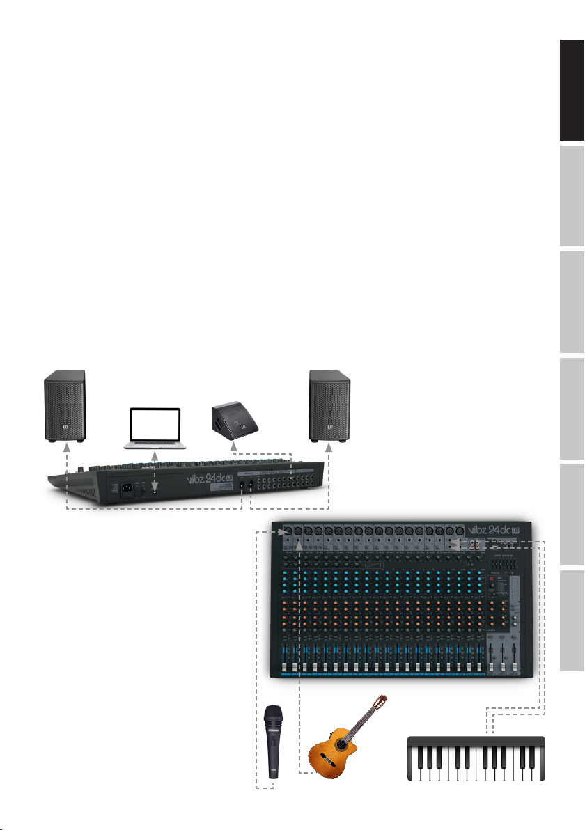
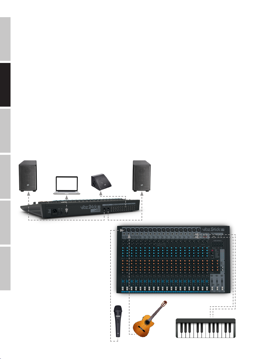
QUICK START GUIDE WITH CABLING EXAMPLE
1. Make sure that the mixer and all devices to be connected to the mixer are turned off.
2. Connect the devices to the mixer using appropriate cables.
3. Adjust the input gain of all the channels and all volume controllers for channels 1 to 23/24 and MAIN MIX to minimum. Place all equalizer controllers in the central position (stop). Adjust the volume controller on the active loudspeaker to minimum. Turn on the +48 V phantom power on the
mixer only if you are using a condenser microphone.
4. Turn on the devices in the following order: microphone and keyboard (or other source devices), then the mixer and lastly the active speakers.
5. Always adjust the gain control of the channels so that the Clip LED of the corresponding channel only lights up briefly when signal peaks occur.
Avoid the permanent lighting of the Clip LED by reducing the input gain (Gain).
6. Press the L-R switch of the channels used to the down position and leave the MUTE switch in the up position, as well as the MUTE switch on the
MAIN MIX sum channel.
7. Bring the volume controllers (Fader) of the channels in use and of the sum channel MAIN MIX approximately to the 0 dB mark.
8. Now increase the volume of the active speakers for the incoming signal (e.g.speaking, singing, keyboard) to the desired level.
9. Fine-tuning can now be achieved by adjusting the volume ratios of the channels and by using the equalizer, compressors and effects device as
desired.
NOTE: When turning off the devices, please follow these steps: First, set the volume of the active speakers to minimum and turn them off, then the
mixer and connected devices can be switched off.
FRANCAISDEUTSCHENGLISH
Active speaker Active speaker
Active monitor
ITALIANOPOLSKIESPAÑOL
5
Page 6
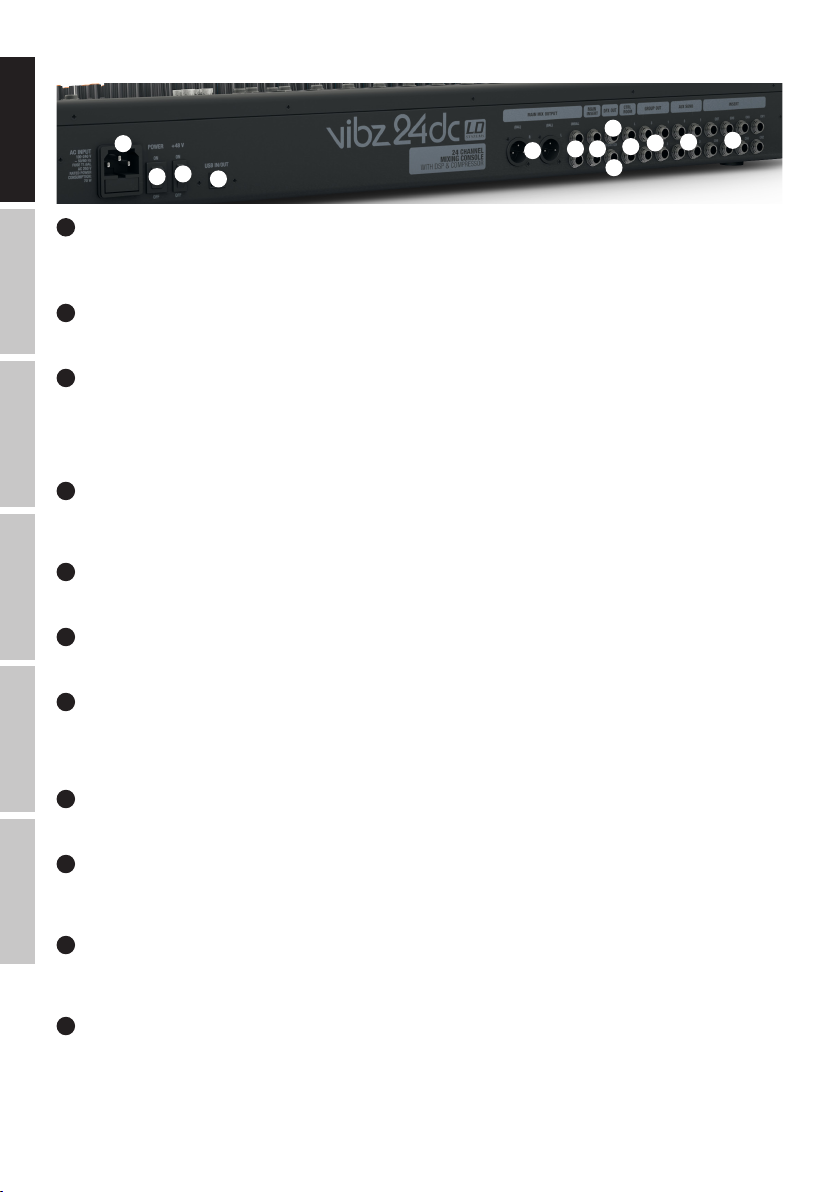
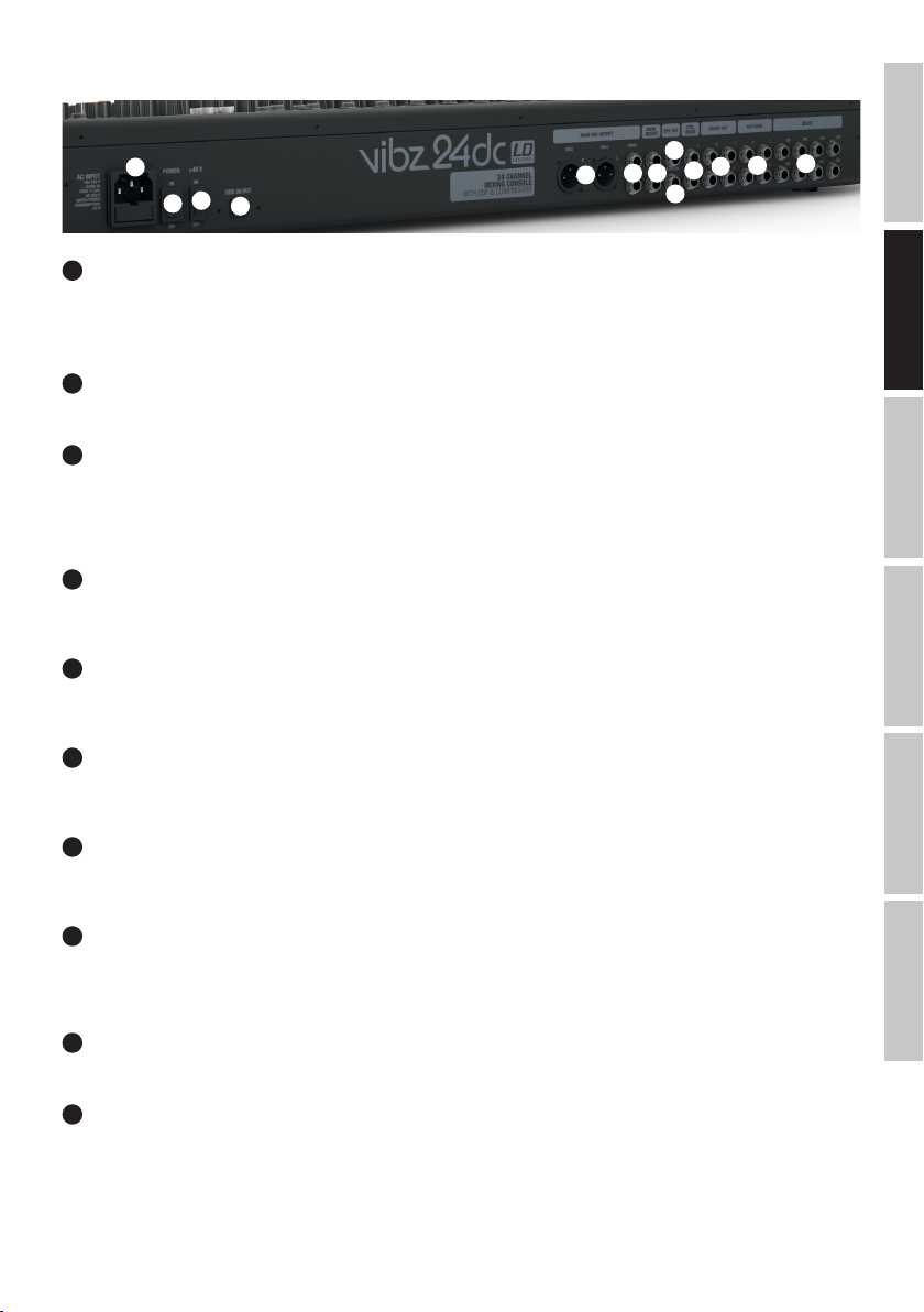
CONNECTIONS, CONTROLS AND INDICATORS
ENGLISH
IEC power socket with built-in fuse holder. An appropriate power cord is included in the delivery.
IMPORTANT INFORMATION: Always replace the fuse only with a fuse of the same type with the same rating (printed on the device). If the fuse blows
repeatedly, please contact an authorised service centre.
DEUTSCHFRANCAIS
On / Off switch for the power supply of the device (ON = enabled).
+48 V phantom power supply for operating high-quality condenser microphones without own power supply. Press down to select the ON position to
turn on the phantom power for the XLR microphone inputs (LED light N 85 is on), and return to the original OFF position to turn it off (red LED light
is off). Turn on the phantom power only after connecting a microphone, or off after disconnecting, and set the volume controller of the microphone
channels to minimum before this step.
The USB-B socket for connecting to a computer with Windows or Mac operating system (Windows XP - Windows 10, MAC OS X, USB 2.0 recording
and playback).
Balanced stereo line output with 3-pin XLR jack sockets to connect an active PA system. Output of the master signal of the mixer.
1
3
2
1
POWER CONNECTOR WITH FUSE HOLDER
2
POWER ON/OFF
3
+48 V ON/OFF
4
USB IN/OUT
5
MAIN MIX OUTPUT (BAL)
4
5
8
7
6
9
12
11
10
ESPAÑOL
6
MAIN MIX OUTPUT (UNBAL)
Unbalanced stereo line output with 6.3 mm jack sockets to connect an active PA system. Output of the master signal of the mixer.
7
MAIN INSERT
Two 3-pin 6.3 mm jack sockets for inserting an external signal processing device (Compressor, Gate, EQ etc.) into the stereo sum channel. A special
insert cable is required for the connection (Y-cable, 1 x stereo jack to 2 x mono jack or XLR). The assignment is as follows: TIP = Send, RING =
Return, SLEEVE = Masse.
13
8
DFX OUT
3-pin 6.3 mm jack socket to output the effects signal
9
FOOT SW (DFX MUTE)
6.3 mm jack socket for connecting a foot switch (pedal) to remotely activate and disable the mute function of the internal effects device (foot switch
optional).
ITALIANO POLSKI
10
CTRL ROOM
Unbalanced line outputs with 6.3 mm jack sockets to connect active listening monitors etc... Output of the sum signal, or of the group signals 1-2 or
3-4 of the mixer or of the PFL signal (adjustable).
11
GROUP OUT 1-4
Unbalanced line outputs with 6.3 mm jack sockets to connect active PA systems etc. Output of the group signals 1 to 4 of the mixer.
6
Page 7
12
AUX SEND 1-4
Unbalanced mono line outputs with 6.3 mm jack sockets to control an external effects device (POST Fader), or
an active stage monitor (PRE Fader).
INSERT CH1 - CH8
13
14
3-pin 6.3 mm jack sockets for inserting an external signal processing device (Compressor, Gate, etc.) in the
corresponding channels 1 to 8. A special insert cable is required for the connection (Y-cable, 1 x stereo jack to
2 x mono jack or XLR). The assignment is as follows: TIP = Send, RING = Return, SLEEVE = Masse.
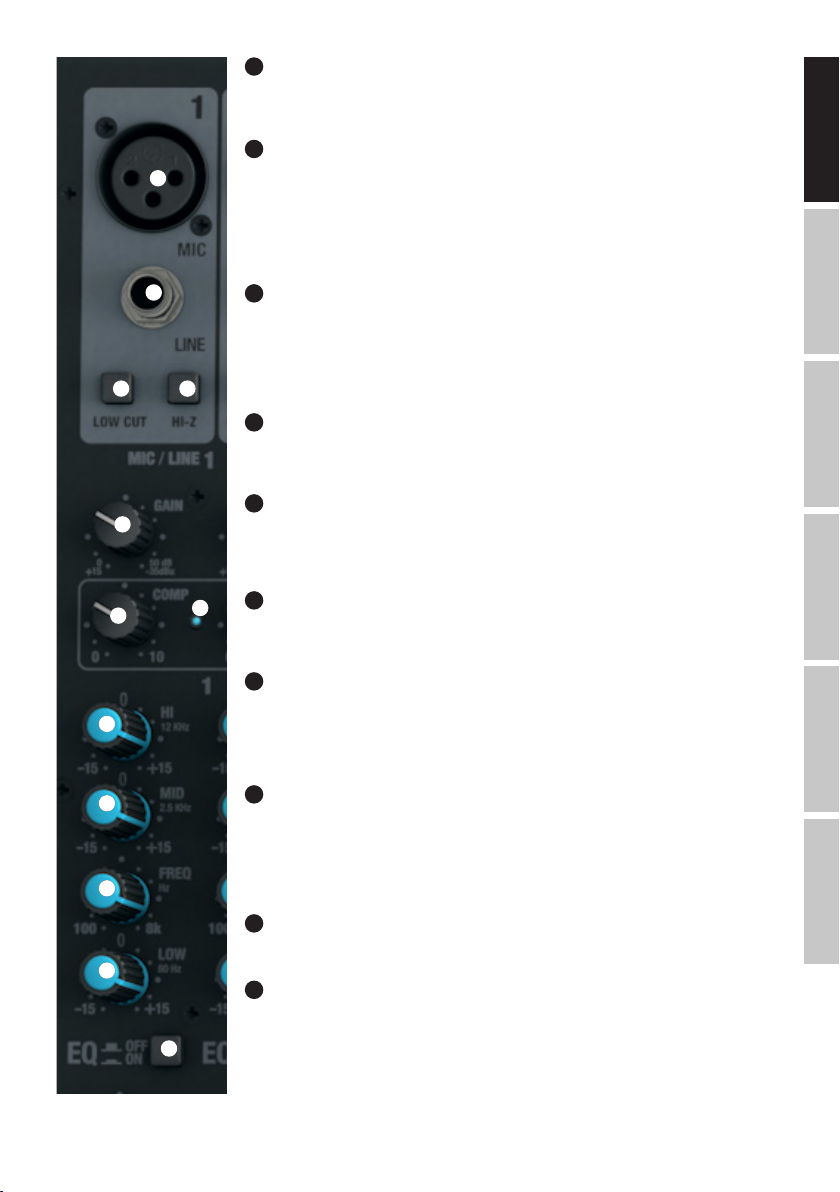
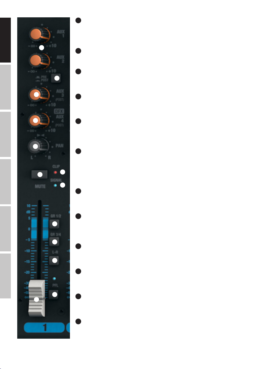
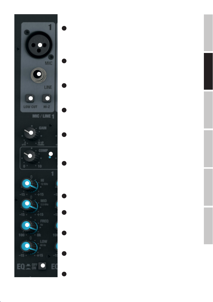
MONO CHANNELS 1 - 16
15
16 17
18
19
21
22
23
14
MIC CHANNEL 1-16
Balanced inputs of the channels 1 to 16 with 3-pin XLR sockets for connecting microphones. A 48 V phantom
power supply is available for operating condenser microphones, and it can be switched centrally to the XLR
sockets (N° 3). Please set the Gain controller (N 18) to minimum (left stop) before connecting or
disconnecting a microphone; and switch on the phantom power only after connecting the microphone, or off
before disconnecting.
15
LINE IN CHANNEL 1-16
Balanced inputs of the mono channels 1 to 16 with 6.3 mm jack to connect a source device with a line level.
Please set the Gain controller (N 18) to minimum (left stop) before connecting or disconnecting jack cables.
16
LOW CUT CHANNEL 1-16
Low cut filter for suppressing low-frequency signals. Especially with voice and singing transmissions, an
activated LOW CUT feature (switch in the down position) can reduce disruptive bass frequencies and thus
increase speech intelligibility. The cut-off frequency is 95 Hz.
17
20
HI-Z CHANNEL 1-4
Using this pressure switch, the inputs of channels 1 to 4 can be switched separately to high impedance
(press switch down for activation). Thus, using instrument channels for guitars or basses is possible.
18
GAIN CHANNEL 1-16
Adjusting the gain of the microphone input from 0 to 50 dB, or the sensitivity of the line input from +15 dBu
to -35 dBu. Adjust the Gain controller so that the Clip LED of the corresponding channel only lights up briefly
when signal peaks occur. Avoid the permanent lighting of the Clip LED by reducing the input gain or input
sensitivity.
19
COMP CHANNEL 1-8
Sliding compressor controller for channels 1 to 8. Depending on the setting, the signal is more or less
compressed, i.e., the dynamics of the signal is restricted (controller to the left stop = compressor is disabled,
controller to the right stop = maximum compression). The level loss caused by the increasingly stronger
compression is automatically compensated by the compressor unit. The use of the compressor can provide
for an improved clarity of a singing voice in the mix.
FRANCAISDEUTSCHENGLISH
ITALIANOPOLSKIESPAÑOL
20
COMP LED
As soon as the compressor is active, the display LED lights up.
24
25
EQUALIZER HI CHANNEL 1-16
21
Equalizer high band for channels 1 to 16 (12 kHz, +/-15 dB). When turned to the left, levels are lowered, when
turned to the right, they are raised. In the centre position (resting point), the equalizer is inactive.
7
Page 8
ENGLISH
22
EQUALIZER MID CHANNEL 1-16
Equalizer mid band for channels 1 to 16 (adjustable frequency, +/-15 dB). When turned to the left, levels
are lowered, when turned to the right, they are raised. In the centre position (resting point), the equalizer is
inactive.
26
27
23
EQUALIZER MID FREQ CHANNEL 1-16
Mid band frequency. Using this controller, set the frequency you want to raise, or lower from 200 Hz to 8 kHz.
EQUALIZER LOW CHANNEL 1-16
24
Equalizer bass band for channels 1 to 16 (80 kHz, +/-15 dB). When turned to the left, levels are lowered,
when turned to the right, they are raised. In the centre position (resting point), the equalizer is inactive.
DEUTSCHFRANCAIS
ESPAÑOL
ITALIANO POLSKI
28
29
30
31
32
34
33
35
36
37
38
EQ ON / OFF CHANNEL 1-16
25
Switch for switching the equalizer (HI, MID, and LOW) on and off. In the down position, the equalizer is
enabled, and in up position, it is disabled.
26
AUX 1 + AUX 2 CHANNEL 1-16
Volume controller for adding the signal from channel 1 to 12 to external effects devices (effect send, switch
N° 27 POST), or for controlling an active stage monitor (Monitor Send, switch N° 27 PRE) Use the line outputs
AUX SEND and 2 control (N 12) for control.
27
AUX 1 + AUX 2 PRE/POST CHANNEL 1-16
When using AUX 1 or AUX 2 to control an external effects device, bring the switch to the down position POST.
The control signal is now picked up after the channel volume controller (N 32), it is therefore dependent on
the latter. To control a stage monitor, bring the switch to the up position PRE. The signal is picked up before
the channel volume controller (N 32) and the volume of the stage monitor can be adjusted independently of
the channel volume.
28
AUX 3 POST CHANNEL 1-16
Volume controller for adding the signal from channel 1 to 16 to external effects devices (Effect Send, Post
Fader). Use the line output AUX SEND 3 (N 12) for activation.
29
LEVEL DFX / AUX 4 POST CHANNEL 1-16
Volume controller for adding the signal from channel 1 to 16 to the internal digital effects device (Effect Send,
Post Fader). Use the line output AUX SEND 4 (N 12) for activating an external effect. When using the AUX
SEND 4 jack socket, the internal effects device is automatically bypassed, and is therefore not usable.
30
PAN CHANNEL 1-16
Using the Panorama controller, position the signal of the corresponding channel in the stereo field of the total
signal (Centre position = perception of the signal in the middle of the stereo field).
31
MUTE CHANNEL 1-16
To mute a channel, press down on the MUTE switch of the corresponding channel. The MUTE LED of the
selected channel then lights up. When disabling the mute function, the MUTE LED goes out.
32
FADER CHANNEL 1-16
Volume controller for channels 1 to 16. Push the Fader button upwards to increase the volume of the
corresponding channel and downwards to decrease it.
33
SIGNAL-LED CHANNEL 1-16
The signal LED lights up as soon as an audio signal is present at the corresponding channel (depending on
the input level and setting of the gain or input sensitivity - GAIN).
8
Page 9

34
CLIP-LED CHANNEL 1-16
Once the red Clip LED lights up, the corresponding channel is operating at the distortion limit. Adjust the Gain controller (N 18) so that the Clip LED
of the corresponding channel only lights up briefly when signal peaks occur. Avoid the permanent lighting of the Clip LED by reducing the input gain
or input sensitivity; if necessary, reduce the volume of an external audio device.
35
GR 1/2 CHANNEL 1-16
Press down on the GR 1/2 switch to add the corresponding channel to the channel group 1 (PAN all the way to the left), to the channel group 2 (PAN
all the way to the right), or to both groups of channel groups 1 and 2 in the same proportion (PAN in central position). The signals of the channels
grouped together in one group are routed simultaneously to the corresponding line outputs GROUP OUT 1/2. The total volume of the resulting group
is adjusted using the volume controller GROUP 1/2 (N 104); if the audio signals of the group are to be routed to the MAIN MIX sum channel, press
down on the L-R switch (N 105).
36
GR 3/4 CHANNEL 1-16
Press down on the GR 3/4 switch to add the corresponding channel to the channel group 3 (PAN all the way to the left), to the channel group 4 (PAN
all the way to the right), or to both groups of channel groups 3 and 4 in the same proportion (PAN in central position). The signals of the channels
grouped together in one group are routed simultaneously to the corresponding line outputs GROUP OUT 3/4. The total volume of the resulting group
is adjusted using the volume controller GROUP 3/4 (N 106); if the audio signals of the group are to be routed to the MAIN MIX sum channel, press
down on the L-R switch (N 107).
37
L-R CHANNEL 1-16
To route an input channel (channel 1 - 16) directly to the MAIN MIX sum channel, press down on the L-R switch of the corresponding channel.
38
PFL CHANNEL 1-16
Press down on the PFL switch (Pre Fader Listening) firstly, to be able to listen to the signal of the respective channel regardless of the channel level
controller (N 32) using headphones connected to the headphone jack PHONES (N 82),secondly, to make a more accurate gain adjustment since
the level of the input signal is now displayed on the 12-segment LED display of the MAIN MIX sum channel. At the same time, the PFL LED of the
corresponding channel and the PFL LED below the level display of the MAIN MIX sum channel light up. If the PFL switch is brought to its original
position, the PFL LED will go out.
FRANCAISDEUTSCHENGLISH
ITALIANOPOLSKIESPAÑOL
9
Page 10
ENGLISH
DEUTSCHFRANCAIS
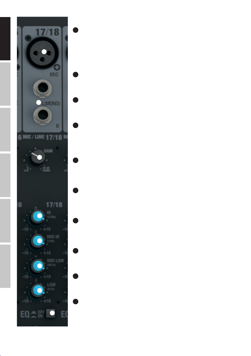
STEREO CHANNELS 17/18 AND 19/20
39
MIC CHANNEL 17/18 AND 19/20
Balanced inputs of the channels 17/18 and 19/20 with 3-pin XLR sockets for connecting microphones.
Channels 17/18 and 19/20 can be used as both mono and stereo channels, depending on the incoming
signal (XLR and jack L IN = Mono / jack L and R IN = Stereo). A 48 V phantom power supply is available for
39
40
operating condenser microphones, and it can be switched centrally to the XLR sockets (N° 3). Please set the
Gain controller (N 41) to minimum (left stop) before connecting or disconnecting a microphone; and switch
on the phantom power only after connecting the microphone, or off before disconnecting.
40
LINE IN L/R CHANNEL 17/18 AND 19/20
Unbalanced inputs for the stereo channels 17/18 and 19/20 with 6.3 mm jacks to connect external devices
with line level (e.g. keyboard). If only the left input jack is used (L), the channel will be mono.
40
LINE IN L/R CHANNEL 17/18 AND 19/20
Unbalanced inputs for the stereo channels 17/18 and 19/20 with 6.3 mm jacks to connect external devices
with line level (e.g. keyboard). If only the left input jack is used (L), the channel will be mono.
41
GAIN CHANNEL 17/18 AND 19/20
Adjusting the gain of the microphone input from 0 to 50 dB, or the sensitivity of the line input from +15 dBu
to -35 dBu. Adjust the Gain controller so that the Clip LED of the corresponding channel only lights up briefly
when signal peaks occur. Avoid the permanent lighting of the Clip LED by reducing the input gain or input
sensitivity; if necessary, reduce the volume of the external audio device.
ESPAÑOL
ITALIANO POLSKI
41
42
43
44
45
46
42
EQUALIZER HI CHANNEL 17/18 AND 19/20
Equalizer high band for channels 17/18 and 19/20 (12 kHz, +/-15 dB). When turned to the left, levels are
lowered, when turned to the right, they are raised. In the centre position (resting point), the equalizer is
inactive.
43
EQUALIZER MID HI CHANNEL 17/18 AND 19/20
Equalizer mid band HI for channels 17/18 and 19/20 (3 kHz, +/-15 dB). When turned to the left, the high mid
levels are lowered, when turned to the right, they are raised. In the centre position (resting point), the equalizer
is inactive.
44
EQUALIZER MID LOW CHANNEL 17/18 AND 19/20
Equalizer mid band LOW for channels 17/18 and 19/20 (500 Hz, +/-15 dB). When turned to the left, the Low
mid levels are lowered, when turned to the right, they are raised. In the centre position (resting point), the
equalizer is inactive.
45
EQUALIZER LOW CHANNEL 17/18 AND 19/20
Equalizer bass band for channels 17/18 and 19/20 (80 Hz, +/-15 dB). When turned to the left, levels are lowered, when turned to the right, they are raised. In the centre position (resting point), the equalizer is inactive.
46
EQ ON / OFF CHANNEL 17/18 AND 19/20
Switch for switching the equalizer (HI, MID HI, MID LOW and LOW) on and off. In the down position, the
equalizer is enabled, and in the up position, it is disabled.
47
AUX 1 + AUX 2 CHANNEL 17/18 AND 19/20
Volume controller for adding the signal from channel 17/18 and 19/20 to external effects devices (Effect Send,
switch N° 48 POST), or for controlling active stage monitors (Monitor Send, switch N° 48 PRE) Use the line
outputs AUX SEND and 2 control (N 12) for control.
10
Page 11
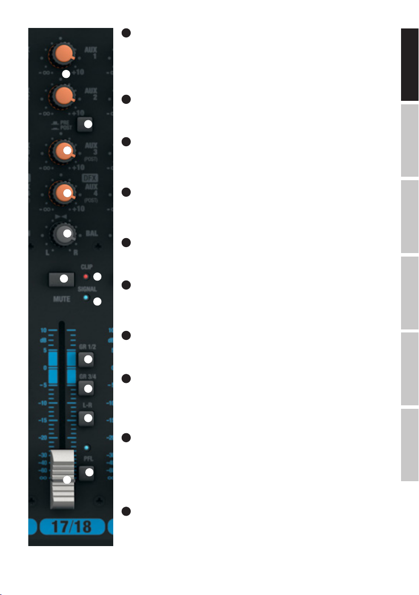
48
AUX 1 + AUX 2 PRE/POST CHANNEL 17/18 AND 19/20
When using AUX 1 or AUX 2 to control an external effects device, bring the switch to the down position POST.
The control signal is now picked up after the channel volume controller (N 53), it is therefore dependent on
the latter. To control a stage monitor, bring the switch to the up position PRE. The signal is picked up before
47
48
49
50
51
52
the channel volume controller (N 53) and the volume of the stage monitor can be adjusted independently of
the channel volume.
49
AUX 3 POST CHANNEL 17/18 AND 19/20
Volume controller for adding the signal from channel 17/18 and 19/20 to an external effects device (Effect
Send, Post Fader). Use the line output AUX SEND 3 (N 12) for activation.
50
LEVEL DFX / AUX 4 POST CHANNEL 17/18 AND 19/20
Volume controller for adding the signal from channel 17/18 and 19/20 to the internal digital effects device
(effect send, post fader). Use the line output AUX SEND 4 (N 12) for activating an external effect. When using
the AUX SEND 4 jack socket, the internal effects device is automatically bypassed, and is therefore not usable.
51
BAL CHANNEL 17/18 AND 19/20
Use the balance controller to set the relative volume between the left and right part of the connected stereo
signal. When only the XLR socket or left socket L (MONO) of the line input of channels 17/18 and 19/20 is in
use, the controller performs the function of a Panorama controller.
52
MUTE CHANNEL 17/18 AND 19/20
To mute a channel, press down on the MUTE switch of the corresponding channel. The MUTE LED of the
selected channel then lights up. When disabling the mute function, the MUTE LED goes out.
55
53
FADER CHANNEL 17/18 AND 19/20
Volume controller for channels 17/18 and 19/20. Push the Fader button upwards to increase the volume of
54
the corresponding channel and
downwards to decrease it.
FRANCAISDEUTSCHENGLISH
54
SIGNAL-LED CHANNEL 17/18 AND 19/20
The signal LED lights up as soon as an audio signal is present at the corresponding channel (depending on
56
57
58
59
53
the input level and setting of the gain or input sensitivity - GAIN).
CLIP-LED CHANNEL 17/18 AND 19/20
55
Once the red Clip LED lights up, the corresponding channel is operating at the distortion limit. Adjust the Gain
controller (N 41) so that the Clip LED of the corresponding channel only lights up briefly when signal peaks
occur. Avoid the permanent lighting of the Clip LED by reducing the input gain or input sensitivity; if necessary,
reduce the volume of an external audio device.
GR 1/2 CHANNEL 17/18 AND 19/20
56
Press down on the GR 1/2 switch to add the corresponding channel to the channel group 1 (BAL all the way
to the left), to the channel group 2 (BAL all the way to the right), or to both groups of channel groups 1 and 2
in the same proportion (BAL in central position). The signals of the channels grouped together in one group
are routed simultaneously to the corresponding line outputs GROUP OUT 1/2. The total volume of the resulting
group is adjusted using the volume controller GROUP 1/2 (N 104); if the audio signals of the group are to be
routed to the MAIN MIX sum channel, press down on the L-R switch (N 105).
GR 3/4 CHANNEL 17/18 AND 19/20
57
Press down on the GR 3/4 switch to add the corresponding channel to the channel group 3 (BAL all the way
to the left), to the channel group 4 (BAL all the way to the right), or to both groups of channel groups 3 and 4
in the same proportion (BAL in central position). The signals of the channels grouped together in one group
are routed simultaneously to the corresponding line outputs GROUP OUT 3/4. The total volume of the resulting
group is adjusted using the volume controller GROUP 3/4 (N 106); if the audio signals of the group are to be
routed to the MAIN MIX sum channel, press down on the L-R switch (N 107).
ITALIANOPOLSKIESPAÑOL
11
Page 12
L-R CHANNEL 17/18 AND 19/20
58
To route an input channel (channel 17/18 and 19/20) directly to the MAIN MIX sum channel, press down on the L-R switch of the corresponding
channel.
PFL CHANNEL 17/18 AND 19/20
59
ENGLISH
Press down on the PFL switch (Pre Fader Listening) firstly, to be able to listen to the signal of the respective channel regardless of the channel level
controller (N 53) using headphones connected to the headphone jack PHONES (N 82), secondly, to make a more accurate gain adjustment since
the level of the input signal is now displayed on the 12-segment LED display of the MAIN MIX sum channel. At the same time, the PFL LED of the
corresponding channel and the PFL LED below the level display of the MAIN MIX sum channel light up. If the PFL switch is brought to its original
position, the PFL LED will go out.
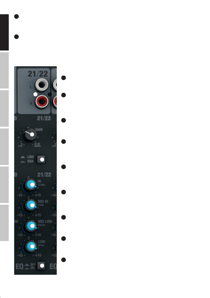
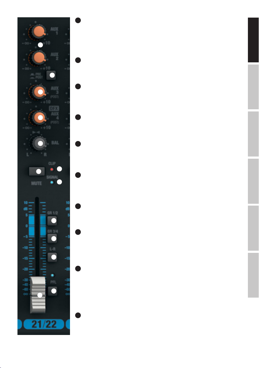
STEREO-CHANNELS 21/22 AND 23/24
LINE IN L/R CHANNEL 21/22 AND 23/24
DEUTSCHFRANCAIS
60
Unbalanced line inputs with RCA jacks L and R.
ESPAÑOL
ITALIANO POLSKI
60
61
62
63
64
65
66
GAIN CHANNEL 21/22 AND 23/24
61
Adjusting the sensitivity of the line input from +15 dBu to -35 dBu. Adjust the Gain controller so that the Clip
LED of the corresponding channel only lights up briefly when signal peaks occur. Avoid the permanent lighting
of the Clip LED by reducing the input sensitivity; if necessary, reduce the volume of the external audio device.
LINE/USB 21/22
62
Select the input source for the stereo channel 21/22. In the up position, the RCA sockets are selected as the
signal source, in the down position the USB interface on the rear side of the mixer is selected.
EQUALIZER HI CHANNEL 21/22 AND 23/24
63
Equalizer high band for channels 21/22 and 23/24 (12 kHz, +/-15 dB). When turned to the left, levels are
lowered, when turned to the right, they are raised. In the centre position (resting point), the equalizer is
inactive.
EQUALIZER MID HI CHANNEL 21/22 AND 23/24
64
Equalizer mid band HIGH for channels 21/22 and 23/24 (3 kHz, +/-15 dB). When turned to the left, the high
mid levels are lowered, when turned to the right, they are raised. In the centre position (resting point), the
equalizer is inactive.
EQUALIZER MID LOW CHANNEL 21/22 AND 23/24
65
Equalizer mid band LOW for channels 21/22 and 23/24 (500 Hz, +/-15 dB). When turned to the left, the Low
mid levels are lowered, when turned to the right, they are raised. In the centre position (resting point), the
equalizer is inactive.
EQUALIZER LOW CHANNEL 21/22 AND 23/24
66
Equalizer bass band for channels 21/22 and 23/24 (80 Hz, +/-15 dB). When turned to the left, levels are lowered, when turned to the right, they are raised. In the centre position (resting point), the equalizer is inactive.
EQ ON/OFF CHANNEL 21/22 AND 23/24
67
Switch for switching the equalizer (HI, MID HI, MID LOW and LOW) on and off. In the down position, the
equalizer is enabled, and in the up position, it is disabled.
12
AUX 1 + AUX 2 CHANNEL 21/22 AND 23/24
68
67
Volume controller for adding the signal from channel 21/22 and 23/24 to external effects devices (Effect Send,
switch N° 69 POST), or for controlling active stage monitors (Monitor Send, switch N° 69 PRE) Use the line
outputs AUX SEND and 2 control (N 12) for control.
Page 13
AUX 1 + AUX 2 PRE/POST CHANNEL 21/22 AND 23/24
69
When using AUX 1 or AUX 2 to control an external effects device, bring the switch to the down position POST.
The control signal is now picked up after the channel volume controller (N 74), it is therefore dependent on
the latter. To control a stage monitor, bring the switch to the up position PRE. The signal is picked up before
68
69
70
71
the channel volume controller (N 74) and the volume of the stage monitor can be adjusted independently of
the channel volume.
AUX 3 POST CHANNEL 21/22 AND 23/24
70
Volume controller for adding the signal from channel 21/22 and 23/24 to an external effects device (Effect
Send, Post Fader). Use the line output AUX SEND 3 (N 12) for activation.
LEVEL DFX / AUX 4 POST CHANNEL 21/22 AND 23/24
71
Volume controller for adding the signal from channel 21/22 and 23/24 to the internal digital effects device
(effect send, post fader). Use the line output AUX SEND 4 (N 12) for activating an external effect. When using
the AUX SEND 4 jack socket, the internal effects device is automatically bypassed, and is therefore not usable.
72
BAL CHANNEL 21/22 AND 23/24
Use the balance controller to set the relative volume between the left and right part of the connected stereo
signal.
FRANCAISDEUTSCHENGLISH
72
73
76
75
77
78
79
MUTE CHANNEL 21/22 AND 23/24
73
To mute a channel, press down on the MUTE switch of the corresponding channel. The MUTE LED of the
selected channel then lights up.
When disabling the mute function, the MUTE LED goes out.
FADER CHANNEL 21/22 AND 23/24
74
Volume controller for channels 21/22 and 23/24. Push the Fader button upwards to increase the volume of
the corresponding channel and
downwards to decrease it.
SIGNAL-LED CHANNEL 21/22 AND 23/24
75
The signal LED lights up as soon as an audio signal is present at the corresponding channel (depending on
the input level and setting of the gain or input sensitivity - GAIN).
76
CLIP-LED CHANNEL 21/22 AND 23/24
Once the red Clip LED lights up, the corresponding channel is operating at the distortion limit. Adjust the Gain
controller (N 61) so that the Clip LED of the corresponding channel only lights up briefly when signal peaks
occur. Avoid the permanent lighting of the Clip LED by reducing the input gain or input sensitivity; if necessary,
reduce the volume of an external audio device.
ITALIANOPOLSKIESPAÑOL
GR 1/2 CHANNEL 21/22 AND 23/24
77
Press down on the GR 1/2 switch to add the corresponding channel to the channel group 1 (BAL all the way
to the left), to the channel group 2 (BAL all the way to the right), or to both groups of channel groups 1 and 2
in the same proportion (BAL in central position). The signals of the channels grouped together in one group
80
74
are routed simultaneously to the corresponding line outputs GROUP OUT 1/2. The total volume of the resulting
group is adjusted using the volume controller GROUP 1/2 (N 104); if the audio signals of the group are to be
routed to the MAIN MIX sum channel, press down on the L-R switch (N 105).
GR 3/4 CHANNEL 21/22 AND 23/24
78
Press down on the GR 3/4 switch to add the corresponding channel to the channel group 3 (BAL all the way
to the left), to the channel group 4 (BAL all the way to the right), or to both groups of channel groups 3 and 4
in the same proportion (BAL in central position). The signals of the channels grouped together in one group
are routed simultaneously to the corresponding line outputs GROUP OUT 3/4. The total volume of the resulting
group is adjusted using the volume controller GROUP 3/4 (N 106); if the audio signals of the group are to be
routed to the MAIN MIX sum channel, press down on the L-R switch (N 107).
13
Page 14
ENGLISH
DEUTSCHFRANCAIS
87
90
ESPAÑOL
L-R CHANNEL 21/22 AND 23/24
79
To route an input channel (channel 21/22 and 23/24) directly to the MAIN MIX sum
channel, press down on the L-R switch of the corresponding channel.
81
83
84
88
91
92
82
85
86
89
98
99
95
100
101
PFL CHANNEL 21/22 AND 23/24
80
Press down on the PFL switch (Pre Fader Listening) firstly, to be able to listen to the
signal of the respective channel regardless of the channel level controller (N 74) using
headphones connected to the headphone jack PHONES (N 82), secondly, to make
a more accurate gain adjustment since the level of the input signal is now displayed
on the 12-segment LED display of the MAIN MIX sum channel (reduce the level of the
input signal when the CLIP LED lights up on the corresponding GAIN controller). At
the same time, the PFL LED of the corresponding channel and the PFL LED below the
level display of the MAIN MIX sum channel light up. If the PFL switch is brought to its
original position, the PFL LED will go out.
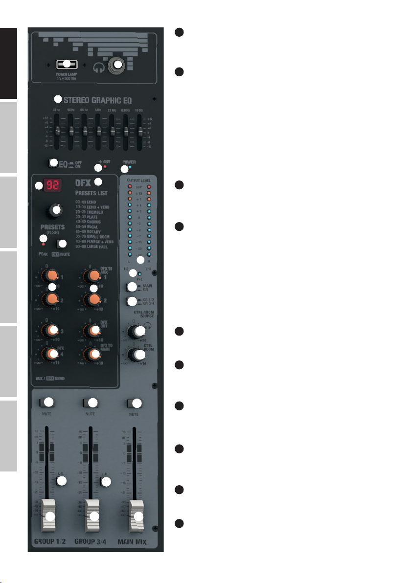
MASTER SECTION
POWER LAMP
81
USB-socket type A to connect a desk lamp. Make sure that the specifications of the
socket and the desk lamp match (5 V DC, a maximum of 500 mA).
HEADPHONE OUTPUT
82
6.3 mm jack socket for connecting a headphone. This connection allows you to listen
to various signals:
A. Switch N 100 (CTRL ROOM SOURCE MAIN/GR) is not pressed down and no PFL
switch is depressed: Sum signal MAIN MIX
B. Switch N 100 is pressed down and no PFL switch is pressed down: Group signal
GROUP GR 1 / 2 or GR 3/4 (observe switch N 101 GR 1/2 / GR 3/4).
C. One or more of the PFL switches of the input channels is pressed down: Corresponding channel/channels is/are picked up before the channel level (Pre Fader
Listening).
ITALIANO POLSKI
14
93 95
94 97
108
105
104 106 110
109
107
111
103
102
STEREO GRAPHIC EQ
83
Graphical 7-band equalizer for the MAIN MIX sum signal.
EQ ON/OFF
84
Switch for switching the sum equalizer (N 83) on and off. In the down position, the
equalizer is enabled, and in the up position, it is disabled.
85
DISPLAY LED +48V
As soon as the phantom power supply of the mixer is switched on, the LED display
+48V lights up (switch N 3 on the rear panel).
POWER LED
86
The Power LED lights up as soon as the mixer is turned on and correctly connected
to the mains.
DISPLAY DFX PRESET
87
2-digit LED display for displaying the effect preset number (00 - 99).
DFX PRESETS (PUSH)
88
Rotary pressure-encoder to select and activate the effect presets. Select the desired
preset by turning the encoder and activate it by pressing on the encoder.
Page 15

DFX PRESETS LIST
89
List of available digital effects.
DFX PEAK LED
90
Once the red Peak LED lights up, the input of the internal effects device is operating at the distortion limit. Adjust the Effect Send level controller DFX
SENDS AUX 4 (N 94) so that the peak LED does not light up when signal peaks occur.
91
DFX MUTE
In order to mute the internal effects device, briefly press the DFX Mute button once, and again to turn mute off. If the effects device is muted, the
peak LED N 90 lights up continuously.
92
SEND AUX 1 AND AUX 2
Volume controller for the sum signal from the input channels 1 to 23/24 routed via the AUX1 and AUX2 volume controllers.
93
SEND AUX 3
Volume controller for the sum signal from the input channels 1 to 23/24 routed via the AUX3 level controller.
SEND AUX 4 / DFX
94
Volume controller for the sum of the signals from the input channels 1 to 23/24 (external or internal effects device) routed via the AUX4 / DFX level
controller (N 10).
DFX TO AUX 1 AND AUX 2
95
Volume controller for adding the effects signal of the internal effects device to output channels AUX 1 and AUX 2.
DFX OUT
96
Volume controller for the volume of the effects signal at the DFX OUT output.
FRANCAISDEUTSCHENGLISH
DFX TO MAIN
97
Volume controller for adding the effects signal of the internal effects device to the MAIN MIX sum channel.
OUTPUT LEVEL
98
2x 12-segment LED level display for visualising the level in the MAIN MIX stereo sum channel and for carrying out a more accurate adjustment of
gain since the volume level of the input signal is displayed on the LED level display when the PFL switch of the corresponding channel is pressed.
To avoid distortion, reduce the output volume of the MAIN MIX volume controller (N 110), or reduce the level of the input signal at the respective
GAIN controller as soon as the red CLIP LED lights up.
PFL-LED
99
The PFL lights up as soon as soon as one (or more) of the PFL switches of the input channels 1 to 23/24 is pressed down.
100
CTRL ROOM SOURCE MAIN / GR
Switcher for selecting the signal source for the signal output CTRL ROOM (N 10) and the headphone output (N 82). In the up position, the MAIN MIX
sum signal is present, in the down position, the group signal GR 1/2 or GR 3/4 is present (observe switch N 101 GR 1/2 / GR 3/4).
101
CTRL ROOM SOURCE GR1/2 / GR3/4
If the CTRL ROOM SOURCE MAIN / GR (N 100) switch is pressed down, either the group signal GR1/2, or GR3/4 can be selected can be selected as
signal source (switch not pressed down = GR1/2, switch pressed down = GR3/4)
102
CTRL ROOM LEVEL
Volume controller for the stereo line output CTRL ROOM (N 10). Before you turn on the power of the connected listening monitor, set the volume
controller to minimum.
ITALIANOPOLSKIESPAÑOL
15
Page 16

103
HEADPHONES LEVEL
Volume controller for the headphone output (N 82). Use headphones with a minimum impedance of 30 ohms and make sure that the volume
stays at a comfortable level, in order to avoid hearing damage caused by loud noise. Before you connect headphones, set the volume controller to
minimum.
ENGLISH
104
GROUP 1/2
Volume controller for the line outputs GROUP OUT 1 and 2 (N 11) and for the adding the group signal GROUP 1/2 to the MAIN MIX sum channel,
when the switch GROUP 1/2 L-R is pressed down (N 105). Before you turn on the power of a connected PA system, set the volume controller to
minimum.
105
GROUP 1/2 L-R
Volume controller for routing the group signal GROUP 1/2 to the MAIN MIX sum channel (down position).
DEUTSCHFRANCAIS
106
GROUP 3/4
Volume controller for the line outputs GROUP OUT 3 and 4 (N 11) and for adding the group signal GROUP 3/4 to the MAIN MIX sum channel, when
the switch GROUP 3/4 L-R is pressed down (N 107). Before you turn on the power of a connected PA system, set the volume controller to minimum.
107
GROUP 3/4 L-R
Volume controller for routing the group signal GROUP 3/4 to the MAIN MIX sum channel (down position).
108
GROUP 1/2 MUTE
Put the switch in the down position to mute the group signal GROUP 1/2. The MUTE LED of the selected channel then lights up. When disabling the
mute function, the MUTE LED goes out.
109
GROUP 3/4 MUTE
Put the switch in the down position to mute the group signal GROUP 3/4. The MUTE LED of the selected channel then lights up. When disabling the
mute function, the MUTE LED goes out.
ESPAÑOL
110
MAIN MIX
Volume controller for the stereo line outputs MAIN MIX OUTPUT N 5 and N 6. Push the Fader button upwards to increase the volume, and
downwards to decrease it. Before you turn on the power of the connected PA system, set the volume controller to minimum.
111
MAIN MIX MUTE
Put the switch in the down position to mute the MAIN MIX sum channel. The MUTE LED of the selected channel then lights up. When disabling the
mute function, the MUTE LED goes out.
INSTALLATION OF THE USB INTERFACE
Installation with Windows operating systems (Windows XP® or newer):
No driver downloads or drivers on external storage media are required for installation. Use the included USB cable to connect the mixer to one of
the USB 2.0 ports of your computer. In most cases, the software is installed automatically. It may be necessary to reboot the computer. In some
cases, a window may appear (device software installation), in which you are prompted to complete installation of the USB audio CODEC software.
ITALIANO POLSKI
Follow this prompt. Now the mixer will appear under “Audio, Video, and Game Controllers” in the Device Manager of your operating system as “USB
Audio CODEC” or “USB Audio Device” and is operational. Depending on the recording software used, it may be necessary to select the mixer in the
“Sound” control panel (“System control “→”Hardware and Sound” →”Sound”) as recording and playback device.
Installation with Apple operating systems (Mac OS X® 10.5 or newer):
No driver downloads or drivers on external storage media are required for installation. Use the included USB cable to connect the mixer to one of the
USB 2.0 ports of your computer. The software is installed automatically. Depending on the recording software used, it may be necessary to select
the mixer (USB Audio CODEC) as an input and output device in the “Sound” control panel (“System settings”→”Sound”).
16
Page 17

SPECIFICATIONS
Model Name: LDVIBZ24DC
Product Type: analogue mixer
Type: live / home recording
Number of Channels: 24
Mono Channels:
Mono Mic/Line Input Channels: 16
Mono Mic/Line Input Connections: 6.3 mm stereo jack, XLR
Mono Mic Input Type: electronically balanced, discreet design
Frequency Response Mono Mic Input: 10 - 45,000 Hz
Amplification Range Mono Mic Input: 50 dB
Channel Crosstalk: 90 dB
THD Mono Mic Input: 0.0058%
Impedance Mono Mic Input: 4 kOhm
S/N Ratio Mono Mic Input: 113 dB
Mono Line Input Type: electronically balanced, discreet design
Amplification Range Mono Line Input: 50 dB
THD Mono Line Input: 0.0045%
Impedance Mono Line Input: 21 kOhm
S/N Ratio Mono Line Input: 116 dB
Mono Channel Equalizer Treble: +/-15 dB @ 12 kHz
Mono Channel Equalizer Mids: +/- 15dB @ 200 Hz - 8 kHz
Mono Channel Equalizer Bass: +/-15 dB @ 80 Hz
Channel Insert: Channel 1 - 8
Channel Insert Connections: 6.3 mm stereo jack (TIP= send / RING= return)
Phantom Power: +48 V DC switchable to XLR inputs
Low Cut: 95 Hz
Hi-Z: jack input channel 1-4 switchable (> 50 kOhm)
Compressor: Channel 1 - 8
Control Elements Channel 1 - 16: Gain, Low Cut, High-Z (channels 1 - 4),Compressor (channels 1 - 8), EQ Hi, EQ Mid, EQ
Mid Freq, EQ Low, EQ on/off, DFX, AUX Send 1-2 pre (AUX2 pre/post switchable), AUX
Send 3-4 post, Channel Mute, Fader Routing switch (Group 1/2, Group 3/4, Main L+R),
Pan/Bal, Channel-Fader, PFL switch
FRANCAISDEUTSCHENGLISH
17
ITALIANOPOLSKIESPAÑOL
Page 18

Stereo Channels:
Stereo Line Input Channels: 4
Stereo Line Input Channels: 2 x 6.3 mm stereo jack (L mono, R) 2 x RCA (cinch)
Stereo Line Input Type: unbalanced
USB In/Out -Connection: USB type B (channel 21/22)
ENGLISH
Frequency Response Stereo Line Input: 10 - 45,000 Hz
Amplification Range Stereo Line Input: 50 dB
Channel Crosstalk: 62 dB
THD Stereo Line Input: 0.0045%
Impedance Stereo Line Input: 3.7 kOhm
S/N Ratio Stereo Line Input: 116 dB
Stereo Channel Equalizer Treble: +/-15 dB @ 12 kHz
DEUTSCHFRANCAIS
Stereo channel equalizer hi-mids: +/-15 dB @ 3 kHz
Stereo channel equalizer low-mids +/-15 dB @ 500 Hz
Stereo Channel Equalizer Bass: +/-15 dB @ 80 Hz
Control Elements Channels 17/18 + 23/24 Gain, LINE/USB -switch (channels 21 - 22), EQ Hi, EQ Mid, EQ Mid Freq, EQ Low, EQ
Master Section:
AUX/Effect Send Channels: 4
AUX/Effect Send Connections: 4 x 6.3 mm stereo jack, unbalanced
Balanced Stereo Main Outputs: 2
Balanced/Unbalanced Stereo Main Output
Connections:
ESPAÑOL
Impedance Balanced Stereo Main Outputs: 120 ohms
Max. Level Balanced/Unbalanced Stereo Main
Outputs:
Stereo Control Room Outputs: 1
Stereo Control Room Output Connections: 2 x 6.3 mm jack
Stereo Outputs (GR OUT): 4
Group Output Connections: 4 x 6.3 mm jack
Headphone Output: 1
Headphone Output Connections: 6.3 mm stereo jack
Minimum Headphone Impedance: 30 ohms
Digital Effects Processor: yes
No. of Presets: 100
Foot Switch Connection DFX Mute: 6.3 mm jack (foot switch optional)
Controls Master Section: 7-band graphic EQ, EQ On/Off, DFX Presets, DFX Mute, AUX/DFX Send 1 - 4, DFX to
ITALIANO POLSKI
on/off, DFX, AUX Send 1-2 pre (AUX2 pre/post switchable), AUX Send 3-4 post, Channel Mute, Fader Routing switch (Group 1/2, Group 3/4, Main L+R), Bal, Channel-Fader,
PFL switch
2 x 6.3 mm stereo jack, 2 x XLR male
22 dBu (20 dBV)
Main, DFX to Aux, Phones, CTRL, GROUP to Main -switch, Phantom Power +48V, Main
Mix Fader, Group Fader, Power, CTRL Room Source MAIN/GR, GR1/2 - GR3/4, Group
Mute, Main Mute
18
Page 19
Specifications:
Display Elements: Channel CLIP, Channel Signal, Channel PFL, Effect CLIP, DFX LED Display, Power,
Phantom Power, 2x 12-segment level meter, Mute LEDs
Connection for desk lamp: USB-A socket, 5 V DC, max. 500 mA
USB In/Out: USB 2.0, 16 Bit Delta-Sigma
DA: 32 kHz, 44,1 kHz, 48 kHz
AD: 8 kHz, 11.025 kHz, 16 kHz, 22.05 kHz, 32 kHz, 44.1 kHz, 48 kHz
Power Connector: IEC power socket
Operating Voltage: 100 - 240 V AC 50/60 Hz
Power Consumption (max.): 70 W
Fuse: T1.6AL / 250 V
Temperature Range For Operation: 0°C to +45°C
Humidity Range For Operation: 10%rel - 80%rel, not condensing
Width: 712 mm
Height: 80 mm
Depth: 425 mm
Weight: 9.36 kg
MANUFACTURER´S DECLARATIONS
MANUFACTURER‘S WARRANTY & LIMITATIONS OF LIABILITY
You can find our current warranty conditions and limitations of liability at: http://www.adamhall.com/media/shop/downloads/documents/
manufacturersdeclarations.pdf. To request warranty service for a product, please contact Adam Hall GmbH, Daimler Straße 9, 61267 Neu
Anspach / Email: Info@adamhall.com / +49 (0)6081 / 9419-0. To enquire about the current declaration of conformity, please contact
info@adamhall.com.
CORRECT DISPOSAL OF THIS PRODUCT
(Valid in the European Union and other European countries with a differentiated waste collection system) This symbol on the product,
or on its documents indicates that the device may not be treated as household waste. This is to avoid environmental damage or
personal injury due to uncontrolled waste disposal. Please dispose of this product separately from other waste and have it recycled to
promote sustainable economic activity. Household users should contact either the retailer where they purchased this product, or their local
government office, for details on where and how they can recycle this item in an environmentally friendly manner. Business users should
contact their supplier and check the terms and conditions of the purchase contract. This product should not be mixed with other commercial
waste for disposal.
FRANCAISDEUTSCHENGLISH
19
ITALIANOPOLSKIESPAÑOL
Page 20

DEUTSCH
SIE HABEN DIE RICHTIGE WAHL GETROFFEN!
Dieses Gerät wurde unter hohen Qualitätsanforderungen entwickelt und gefertigt, um viele Jahre einen reibungslosen Betrieb zu gewährleisten. Dafür steht LD Systems mit seinem Namen und der langjährigen Erfahrung als Hersteller hochwertiger Audioprodukte. Bitte lesen
Sie diese Bedienungsanleitung sorgfältig, damit Sie Ihr neues Produkt von LD Systems schnell optimal einsetzen können.
ENGLISH
Mehr Informationen zu LD SYSTEMS finden Sie auf unserer Internetseite WWW.LD-SYSTEMS.COM
SICHERHEITSHINWEISE
1. Lesen Sie diese Anleitung bitte sorgfältig durch.
2. Bewahren Sie alle Informationen und Anleitungen an einem sicheren Ort auf.
3. Befolgen Sie die Anweisungen.
4. Beachten Sie alle Warnhinweise. Entfernen Sie keine Sicherheitshinweise oder andere Informationen vom Gerät.
5. Verwenden Sie das Gerät nur in der vorgesehenen Art und Weise.
6. Verwenden Sie ausschließlich stabile und passende Stative bzw. Befestigungen (bei Festinstallationen). Stellen Sie sicher, dass Wandhalterungen
ordnungsgemäß installiert und gesichert sind. Stellen Sie sicher, dass das Gerät sicher installiert ist und nicht herunterfallen kann.
DEUTSCHFRANCAIS
7. Beachten Sie bei der Installation die für Ihr Land geltenden Sicherheitsvorschriften.
8. Installieren und betreiben Sie das Gerät nicht in der Nähe von Heizkörpern, Wärmespeichern, Öfen oder sonstigen Wärmequellen. Sorgen Sie
dafür, dass das Gerät immer so installiert ist, dass es ausreichend gekühlt wird und nicht überhitzen kann.
9. Platzieren Sie keine Zündquellen wie z.B. brennende Kerzen auf dem Gerät.
10. Lüftungsschlitze dürfen nicht blockiert werden.
11. Das Gerät wurde ausschließlich für die Verwendung in Innenräumen entwickelt, betreiben Sie das Gerät nicht in unmittelbarer Nähe von Wasser
(gilt nicht für spezielle Outdoor Geräte - beachten Sie in diesem Fall bitte die im Folgenden vermerkten Sonderhinweise). Bringen Sie das Gerät nicht
mit brennbaren Materialien, Flüssigkeiten oder Gasen in Berührung.
12. Sorgen Sie dafür, dass kein Tropf- oder Spritzwasser in das Gerät eindringen kann. Stellen Sie keine mit Flüssigkeit gefüllten Behältnisse wie
Vasen oder Trinkgefäße auf das Gerät.
13. Sorgen Sie dafür, dass keine Gegenstände in das Gerät fallen können.
14. Betreiben Sie das Gerät nur mit dem vom Hersteller empfohlenen und vorgesehenen Zubehör.
15. Öffnen Sie das Gerät nicht und verändern Sie es nicht.
16. Überprüfen Sie nach dem Anschluss des Geräts alle Kabelwege, um Schäden oder Unfälle, z. B. durch Stolperfallen zu vermeiden.
17. Achten Sie beim Transport darauf, dass das Gerät nicht herunterfallen und dabei möglicherweise Sach- und Personenschäden verursachen
kann.
18. Wenn Ihr Gerät nicht mehr ordnungsgemäß funktioniert, Flüssigkeiten oder Gegenstände in das Geräteinnere gelangt sind, oder das Gerät
anderweitig beschädigt wurde, schalten Sie es sofort aus und trennen es von der Netzsteckdose (sofern es sich um ein aktives Gerät handelt).
Dieses Gerät darf nur von autorisiertem Fachpersonal repariert werden.
ESPAÑOL
19. Verwenden Sie zur Reinigung des Geräts ein trockenes Tuch.
20. Beachten Sie alle in Ihrem Land geltenden Entsorgungsgesetze. Trennen Sie bei der Entsorgung der Verpackung bitte Kunststoff und Papier bzw.
Kartonagen voneinander.
21. Kunststoffbeutel müssen außer Reichweite von Kindern aufbewahrt werden.
BEI GERÄTEN MIT NETZANSCHLUSS:
22. ACHTUNG: Wenn das Netzkabel des Geräts mit einem Schutzkontakt ausgestattet ist, muss es an einer Steckdose mit Schutzleiter
angeschlossen werden. Deaktivieren Sie niemals den Schutzleiter eines Netzkabels.
23. Schalten Sie das Gerät nicht sofort ein, wenn es starken Temperaturschwankungen ausgesetzt war (beispielsweise nach dem Transport).
Feuchtigkeit und Kondensat könnten das Gerät beschädigen. Schalten Sie das Gerät erst ein, wenn es Zimmertemperatur erreicht hat.
24. Bevor Sie das Gerät an die Steckdose anschließen, prüfen Sie zuerst, ob die Spannung und die Frequenz des Stromnetzes mit den auf dem
Gerät angegebenen Werten übereinstimmen. Verfügt das Gerät über einen Spannungswahlschalter, schließen Sie das Gerät nur an die Steckdose
an, wenn die Gerätewerte mit den Werten des Stromnetzes übereinstimmen. Wenn das mitgelieferte Netzkabel bzw. der mitgelieferte Netzadapter
nicht in Ihre Netzsteckdose passt, wenden Sie sich an Ihren Elektriker.
25. Treten Sie nicht auf das Netzkabel. Sorgen Sie dafür, dass spannungsführende Kabel speziell an der Netzbuchse bzw. am Netzadapter und der
Gerätebuchse nicht geknickt werden.
26. Achten Sie bei der Verkabelung des Geräts immer darauf, dass das Netzkabel bzw. der Netzadapter stets frei zugänglich ist. Trennen Sie das
Gerät stets von der Stromzuführung, wenn das Gerät nicht benutzt wird, oder Sie das Gerät reinigen möchten. Ziehen Sie Netzkabel und Netzadapter immer am Stecker bzw. am Adapter und nicht am Kabel aus der Steckdose. Berühren Sie Netzkabel und Netzadapter niemals mit nassen
ITALIANO POLSKI
Händen.
27. Schalten Sie das Gerät möglichst nicht schnell hintereinander ein und aus, da sonst die Lebensdauer des Geräts beeinträchtigt werden könnte.
28. WICHTIGER HINWEIS: Ersetzen Sie Sicherungen ausschließlich durch Sicherungen des gleichen Typs und Wertes. Sollte eine Sicherung
wiederholt auslösen, wenden Sie sich bitte an ein autorisiertes Servicezentrum.
29. Um das Gerät vollständig vom Stromnetz zu trennen, entfernen Sie das Netzkabel bzw. den Netzadapter aus der Steckdose.
30. Wenn Ihr Gerät mit einem Volex-Netzanschluss bestückt ist, muss der passende Volex-Gerätestecker entsperrt werden, bevor er entfernt werden
kann. Das bedeutet aber auch, dass das Gerät durch ein Ziehen am Netzkabel verrutschen und herunterfallen kann, wodurch Personen verletzt
werden und/oder andere Schäden auftreten können. Verlegen Sie Ihre Kabel daher immer sorgfältig.
31. Entfernen Sie Netzkabel und Netzadapter aus der Steckdose bei Gefahr eines Blitzschlags oder wenn Sie das Gerät länger nicht verwenden.
32. Das Gerät darf nur im spannungsfreien Zustand (Trennung des Netzsteckers vom Stromnetz) installiert werden.
33. Staub und andere Ablagerungen im Inneren des Geräts können es beschädigen. Das Gerät sollte je nach Umgebungsbedingungen (Staub,
Nikotin, Nebel etc.) regelmäßig von qualifiziertem Fachpersonal gewartet bzw. gesäubert werden (keine Garantieleistung), um Überhitzung und
20
Page 21
Fehlfunktionen zu vermeiden.
34. Der Abstand zu brennbaren Materialien muss mindestens 0,5 m betragen
35. Netzleitungen zur Spannungsversorgung mehrerer Geräte müssen mindestens 1,5 mm² Aderquerschnitt aufweisen. In der EU müssen die
Leitungen H05VV-F, oder gleichartig, entsprechen. Geeignete Leitungen werden von Adam Hall angeboten. Mit diesen Leitungen können Sie
mehrere Geräte über den Power out Anschluss mit dem Power IN Anschluss eines weiteren Gerätes verbinden. Beachten Sie, dass die gesamte
Stromaufnahme aller angeschlossenen Geräte den vorgegebenen Wert nicht überschreitet (Aufdruck auf dem Gerät). Achten Sie darauf,
Netzleitungen so kurz wie möglich zu halten.
ACHTUNG
Entfernen Sie niemals die Abdeckung, da sonst das Risiko eines elektrischen Schlages besteht. Im
Inneren des Geräts befinden sich keine Teile, die vom Bediener repariert oder gewartet werden können.
Lassen Sie Wartung und Reparaturen ausschließlich von qualifiziertem Servicepersonal durchführen.
Das gleichseitige Dreieck mit Blitzsymbol warnt vor nichtisolierten, gefährlichen Spannungen im Geräteinneren, die einen elektrischen
Schlag verursachen können.
Das gleichseitige Dreieck mit Ausrufungszeichen kennzeichnet wichtige Bedienungs- und Wartungshinweise.
Warnung! Dieses Symbol kennzeichnet heiße Oberflächen. Während des Betriebs können bestimmte Teile des Gehäuses heiß werden.
Berühren oder transportieren Sie das Gerät nach einem Einsatz erst nach einer Abkühlzeit von mindestens 10 Minuten.
ACHTUNG HOHE LAUTSTÄRKEN BEI AUDIOPRODUKTEN!
Dieses Gerät ist für den professionellen Einsatz vorgesehen. Der kommerzielle Betrieb dieses Geräts unterliegt den jeweils gültigen nationalen
Vorschriften und Richtlinien zur Unfallverhütung. Als Hersteller ist Adam Hall gesetzlich verpflichtet, Sie ausdrücklich auf mögliche Gesundheitsrisiken hinzuweisen. Gehörschäden durch hohe Lautstärken und Dauerbelastung: Bei der Verwendung dieses Produkts können hohe Schalldruckpegel
(SPL) erzeugt werden, die bei Künstlern, Mitarbeitern und Zuschauern zu irreparablen Gehörschäden führen können. Vermeiden Sie länger
anhaltende Belastung durch hohe Lautstärken über 90 dB.
VORSICHT! WICHTIGE HINWEISE IN BEZUG AUF LICHT-PRODUKTE!
1. Das Produkt ist für den professionellen Einsatz im Bereich der Veranstaltungstechnik entwickelt worden und ist nicht für die Raumbeleuchtung in
Haushalten geeignet.
2. Blicken Sie niemals, auch nicht kurzzeitig, direkt in den Lichtstrahl.
3. Blicken Sie niemals mit optischen Geräten wie Vergrößerungsgläsern in den Lichtstrahl.
4. Stoboskopeffekte können unter Umständen bei empfindlichen Menschen epileptische Anfälle auslösen! Epilepsiekranke Menschen sollten daher
unbedingt Orte meiden, an denen Stroboskope eingesetzt werden.
EINFÜHRUNG
LDVIBZ24DC - 24-Kanal Mixer mit digitaler Effektsektion und Kompressoren
Das VIBZ 24 DC ist ein vielseitig einsetzbares Mischpult mit sechzehn symmetrischen Mikrofoneingängen, die über hochwertige Vorverstärker,
Low-Cut-Filter, einen effektiven 3-Band-EQ mit semiparametrischen Mitten und zuschaltbare Phantomspeisung verfügen, zwei weitere können
alternativ als Stereo-Line-Kanäle benutzt werden.
Acht Mikrofonkanäle können mit dem eingebauten Kompressor für eine wirkungsvolle Dynamikregelung separat bearbeitet werden.
Die Stereokanäle sind mit 4-Band-EQs ausgestattet.
Die Mastersektion des Mischpults beinhaltet u.a. zwei Effektwege, symmetrische XLR-Ausgänge, Gruppen- und Monitorausgänge sowie einen
Kopfhöreranschluß. Der VIBZ 24 DC besitzt zudem eine USB-Schnittstelle für Tonaufzeichnungen direkt auf den Rechner, eine digitale Effektsektion
mit 100 Presets und einem Anschluss für eine 5V Pult-Leuchte.
Mit wichtigen Ausstattungs-Details wie der PFL-Funktion oder Mute-Tastern und seinem natürlichen, transparenten Klang ist der VIBZ 24 DC die
perfekte Wahl für den Live-Einsatz, Installationen und anspruchsvolle Homerecording-Anwendungen.
FRANCAISDEUTSCHENGLISH
ITALIANOPOLSKIESPAÑOL
21
Page 22
SCHNELLSTARTANLEITUNG MIT VERKABELUNGSBEISPIEL
1. Achten Sie darauf, dass das Mischpult und alle Geräte, die am Mischpult angeschlossen werden sollen, ausgeschaltet sind.
2. Schließen Sie die Geräte mit geeigneten Kabeln am Mischpult an.
3. Stellen Sie die Vorverstärkung aller Kanäle und alle Pegelsteller Kanal 1 bis 23/24 und MAIN MIX auf Minimum. Bringen Sie die Regler aller
ENGLISH
Equalizer in Mittelstellung (Rastpunkt). Stellen Sie die Lautstärkeregler der aktiven Lautsprecher auf Minimum. Schalten Sie die +48V
Phantomspeisung des Mischpults nur ein, wenn Sie ein Kondensatormikrofon verwenden.
4. Schalten Sie die Geräte in der folgenden Reihenfolge ein: Mikrofon und Keyboard (oder andere Instrumente / Zuspielgeräte), das Mischpult und
zuletzt die aktiven Lautsprecher.
5. Stellen Sie die Gain-Regler der Kanäle so ein, dass die Clip-LED des entsprechenden Kanals nur bei Pegelspitzen des anliegenden Signals kurz
aufleuchtet. Vermeiden Sie permanentes Leuchten der Clip-LED durch Reduzieren der Eingangsvorverstärkung (Gain).
DEUTSCHFRANCAIS
6. Bringen Sie den Schalter L-R der verwendeten Kanäle in die heruntergedrückte Position und den MUTE-Schalter in die nicht heruntergedrückte
Position, ebenso den MUTE-Schalter des Summenkanals MAIN MIX.
7. Bringen Sie die Pegelsteller (Fader) der verwendeten Kanäle und des Summenkanals MAIN MIX ungefähr auf die 0 dB Markierung.
8. Erhöhen Sie bei anliegendem Signal (z.B. Sprache, Gesang, Keyboard) nun die Lautstärke der aktiven Lautsprecher auf den gewünschten Pegel.
9. Die Feinabstimmung durch das Einstellen der Lautstärkenverhältnisse der Kanäle und die Verwendung der Equalizer, Kompressoren und des
Effektgeräts kann nun nach Wunsch durchgeführt werden.
HINWEIS: Beim Ausschalten der Geräte beachten Sie bitte folgende Schritte: Stellen Sie zuerst die Lautstärke der aktiven Lautsprecher auf
Minimum und schalten Sie aus, danach können das Mischpult und die angeschlossenen Geräte ausgeschaltet werden.
ESPAÑOL
ITALIANO POLSKI
Aktivlautsprecher Aktivlautsprecher
Aktivmonitor
22
Page 23
ANSCHLÜSSE, BEDIEN- UND ANZEIGEELEMENTE
8
1
3
2
1
NETZBUCHSE UND SICHERUNGSSCHALTER
IEC Netzbuchse mit integriertem Sicherungshalter. Ein geeignetes Netzkabel befindet sich im Lieferumfang.
WICHTIGER HINWEIS: Ersetzen Sie die Sicherung ausschließlich durch eine Sicherung des gleichen Typs und mit gleichen Werten entsprechend
des Aufdrucks auf dem Gerät! Sollte die Sicherung wiederholt auslösen, wenden Sie sich bitte an ein autorisiertes Servicezentrum.
2
POWER ON/OFF
Ein- / Ausschalter für die Spannungszufuhr des Geräts (ON = eingeschaltet).
3
+48 V ON/OFF
+48 V Phantomspeisung für den Betrieb von Kondensatormikrofonen ohne eigene Spannungsversorgung. Bringen Sie den Schalter in die Position
ON, um die Phantomspeisung für die XLR Mikrofon-Eingänge einzuschalten (Anzeige-LED Nr. 85 leuchtet) und in die nicht heruntergedrückte
Position OFF, um sie auszuschalten (rote Anzeige-LED erlischt). Schalten Sie die Phantomspeisung erst nach dem Anschließen eines Mikrofons ein,
bzw. vor dem Ausstecken aus und stellen vor einem Schaltvorgang die Pegelsteller der Mikrofonkanäle auf Minimum.
4
USB IN/OUT
USB-B Anschlussbuchse zum Verbinden mit einem Computer mit Windows-, oder MAC-Betriebssystem (Windows XP - Windows 10, MAC OS X,
USB 2.0 Recording und Playback).
4
USB IN/OUT
USB-B Anschlussbuchse zum Verbinden mit einem Computer mit Windows-, oder MAC-Betriebssystem (Windows XP - Windows 10, MAC OS X,
USB 2.0 Recording und Playback).
5
MAIN MIX OUTPUT (BAL)
Symmetrischer Stereo-Line-Ausgang mit 3-Pol XLR-Buchsen zum Anschließen einer aktiven Beschallungsanlage. Ausgabe des Summen-Signals
des Mischpults.
4
6
5
11
10
7
9
13
12
FRANCAISDEUTSCHENGLISH
6
MAIN MIX OUTPUT (UNBAL)
Unsymmetrischer Stereo-Line-Ausgang mit 6,3mm Klinkenbuchsen zum Anschließen einer aktiven Beschallungsanlage. Ausgabe des SummenSignals des Mischpults.
7
MAIN INSERT
Zwei 3-polige 6,3mm Klinkenbuchsen zum Einschleifen eines externen signalverarbeitenden Geräts (Compressor, Gate, EQ usw.) in den Stereo
Summen-Kanal. Für die Verbindung wird ein spezielles Insert-Kabel benötigt (Y-Kabel, 1x Stereo-Klinke auf 2x Mono-Klinke, bzw. XLR).
Die Belegung der Buchse ist wie folgt: TIP = Send, RING = Return, SLEEVE = Masse.
8
DFX OUT
3-polige 6,3mm Klinkenbuchse zum Ausgeben des Effektsignals.
9
FOOT SW (DFX MUTE)
6,3mm Klinkenbuchse zum Anschließen eines Fußtasters (Schließer) um die Stummschaltung des internen Effektgeräts ferngesteuert zu aktivieren
und deaktivieren (Fußtaster optional).
ITALIANOPOLSKIESPAÑOL
23
Page 24

10
CTRL ROOM
Unsymmetrische Line-Ausgänge mit 6,3mm Klinkenbuchsen zum Anschließen von aktiven Abhör-Monitoren etc.. Ausgabe des Summen-Signals,
oder der Gruppen-Signale 1-2, bzw. 3-4 des Mischpults, oder des PFL-Signals (umschaltbar).
11
GROUP OUT 1-4
ENGLISH
Unsymmetrische Line-Ausgänge mit 6,3mm Klinkenbuchsen zum Anschließen von aktiven Beschallungsanlagen etc.. Ausgabe der Gruppen-Signale
1 bis 4 des Mischpults.
12
AUX SEND 1-4
Unsymmetrische Mono-Line-Ausgänge mit 6,3mm Klinkenbuchsen zum Ansteuern externer Effektgeräte (POST Fader), oder aktiver
Bühnenmonitore (PRE Fader).
13
DEUTSCHFRANCAIS
INSERT CH1 - CH8
3-polige 6,3mm Klinkenbuchsen zum Einschleifen externer signalverarbeitender Geräte (Compressor, Gate usw.) in die entsprechenden Kanäle 1 bis
8. Für die Verbindung wird ein spezielles Insert-Kabel benötigt (Y-Kabel, 1x Stereo-Klinke auf 2x Mono-Klinke, bzw. XLR). Die Belegung der Buchse
ist wie folgt: TIP = Send, RING = Return, SLEEVE = Masse.
ESPAÑOL
ITALIANO POLSKI
24
Page 25
15
16 17
18
19
21
MONO-KANÄLE 1-16
14
MIC KANAL 1-16
Symmetrische Eingänge der Kanäle 1 bis 16 mit 3-Pol XLR-Buchsen zum Anschließen von Mikrofonen. Für
den Betrieb von Kondensator-Mikrofonen steht eine 48V Phantomspeisung zur Verfügung, die zentral auf die
14
XLR-Buchsen zugeschaltet werden kann (Nr. 3). Vor dem Ein- bzw. Ausstecken von Mikrofonen stellen Sie den
Gain-Regler (Nr. 18) bitte auf ein Minimum (Linksanschlag) und schalten die Phantomspeisung erst nach dem
Anschließen eines Mikrofons ein, bzw. vor dem Ausstecken aus.
15
LINE IN KANAL 1-16
Symmetrische Eingänge der Mono-Kanäle 1 bis 16 mit 6,3mm Klinkenbuchse zum Anschließen eines
Zuspielgeräts mit Line-Pegel. Vor dem Ein- bzw. Ausstecken von Klinkenkabeln stellen Sie den Gain-Regler
(Nr. 18) bitte auf ein Minimum (Linksanschlag).
16
LOW CUT KANAL 1-16
Tiefensperre für die Unterdrückung tieffrequenter Signalanteile. Vor allem bei Sprach- und Gesangsübertragung kann ein aktivierter LOW CUT (Schalter in heruntergedrückter Position) störende Bassfrequenzen
absenken und somit die Textverständlichkeit steigern. Die Grenzfrequenz liegt bei 95 Hz.
17
HI-Z KANAL 1-4
Mit Hilfe dieses Druckschalters können die Klinken-Eingänge der Kanäle 1 bis 4 separat hochohmig
geschaltet werden (zum Aktivieren Schalter herunterdrücken). Somit wird die Verwendung als
Instrumenten-Kanäle für z.B. Gitarren, oder Bässe ermöglicht.
18
GAIN KANAL 1-16
Justieren der Vorverstärkung des Mikrofon-Eingangs von 0 bis 50 dB, bzw. der Empfindlichkeit des Line-Eingangs von +15 bis -35 dBu. Stellen Sie den Gain-Regler so ein, dass die Clip-LED des entsprechenden Kanals
nur bei Pegelspitzen des anliegenden Signals kurz aufleuchtet. Vermeiden Sie permanentes Leuchten der
Clip-LED durch Reduzierung der Eingangsvorverstärkung, bzw. der Eingangsempfindlichkeit.
20
19
COMP KANAL 1-8
Stufenlos regelbarer Compressor für die Kanäle 1 bis 8. Je nach Einstellung wird das anliegende Signal
weniger, oder stärker verdichtet, d.h., die Dynamik des Signals wird eingeschränkt (Linksanschlag des
Reglers = Compressor deaktiviert, Rechtsanschlag = maximale Verdichtung). Der durch zunehmend stärkerer
Verdichtung größer werdende Pegelverlust wird von der Compressor-Einheit automatisch ausgeglichen. Der
Einsatz des Compressors kann z.B. für eine verbesserte Durchsetzung einer Gesangsstimme im Mix sorgen.
FRANCAISDEUTSCHENGLISH
20
COMP LED
22
23
24
25
Sobald der Compressor aktiv ist, leuchtet die Anzeige-LED.
21
EQUALIZER HI KANAL 1-16
Equalizer Höhenband für die Kanäle 1 bis 16 (12 kHz, +/-15 dB). Nach links gedreht werden Höhen
abgesenkt, nach rechts gedreht angehoben. In Mittelstellung (Rastpunkt) ist der Equalizer inaktiv.
22
EQUALIZER MID KANAL 1-16
Equalizer Mittenband für die Kanäle 1 bis 16 (einstellbare Frequenz, +/-15 dB). Nach links gedreht werden
Mitten abgesenkt, nach rechts gedreht angehoben. In Mittelstellung (Rastpunkt) ist der Equalizer inaktiv.
23
EQUALIZER MID FREQ KANAL 1-16
Mittenband-Frequenz. Stellen Sie die Frequenz, die Sie anheben, oder absenken wollen, mit Hilfe dieses
Reglers von 200Hz bis 8kHz ein.
24
EQUALIZER LOW KANAL 1-16
Equalizer Bassband für die Kanäle 1 bis 16 (80 Hz, +/-15 dB). Nach links gedreht werden Bässe abgesenkt,
nach rechts gedreht angehoben. In Mittelstellung (Rastpunkt) ist der Equalizer inaktiv.
ITALIANOPOLSKIESPAÑOL
25
Page 26
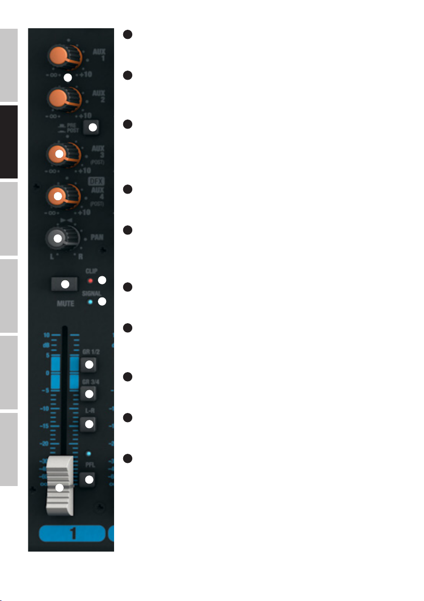
ENGLISH
DEUTSCHFRANCAIS
ESPAÑOL
25
EQ ON / OFF KANAL 1-16
Schalter zum Ein- und Ausschalten des Equalizers (HI, MID und LOW). In heruntergedrückter Position ist der
Equalizer aktiviert, in nicht heruntergedrückter Position deaktiviert.
26
26
27
28
29
30
31
34
33
AUX 1 + AUX 2 KANAL 1-16
Pegelsteller für die Zumischung des Signals von Kanal 1 bis 16 auf externe Effektgeräte (Effekt Send, Schalter
Nr. 27 POST), oder für die Ansteuerung aktiver Bühnenmonitore (Monitor Send, Schalter Nr. 27 PRE).
Verwenden Sie die Line-Ausgänge AUX SEND 1 und 2 (Nr. 12) zur Ansteuerung.
27
AUX 1 + AUX 2 PRE/POST KANAL 1-16
Wenn Sie AUX 1 bzw. AUX 2 zur Ansteuerung eines externen Effektgeräts verwenden, bringen Sie den Schalter in die heruntergedrückte Position POST. Das Ansteuerungsignal wird nun hinter dem Kanal-Pegelsteller (Nr.
32) abgegriffen, ist also abhängig davon. Zur Ansteuerung eines Bühnenmonitors, bringen Sie den Schalter in
die nicht heruntergedrückte Position PRE. Das Signal wird nun vor dem Kanal-Pegelsteller (Nr. 32) abgegriffen
und die Lautstärke des Bühnenmonitors kann unabhängig von der Kanal-Lautstärke eingestellt werden.
28
AUX 3 POST KANAL 1-16
Pegelsteller für die Zumischung des Signals von Kanal 1 bis 16 auf ein externes Effektgeräte (Effekt Send,
Post Fader). Verwenden Sie den Line-Ausgang AUX SEND 3 (Nr. 12) zur Ansteuerung.
29
LEVEL DFX / AUX 4 POST KANAL 1-16
Pegelsteller für die Zumischung des Signals von Kanal 1 bis 16 auf das interne digitale Effektgerät (Effekt
Send, Post Fader). Verwenden Sie den Line-Ausgang AUX SEND 4 (Nr. 12) zur Ansteuerung eines externen
Effektgeräts. Bei der Verwendung der AUX SEND 4-Klinkenbuchse, wird das interne Effektgerät automatisch
umgangen und ist somit nicht verwendbar.
30
PAN KANAL 1-16
Mit Hilfe des Panorama-Reglers positionieren Sie das Signal des entsprechenden Kanals im Stereofeld des
Gesamtsignals (Mittelstellung = Wahrnehmung des Signals in der Mitte des Stereofelds).
ITALIANO POLSKI
26
31
MUTE KANAL 1-16
Um einen Kanal stummzuschalten, bringen Sie den MUTE-Schalter des entsprechenden Kanals in die
heruntergedrückte Position. Gleichzeitig beginnt die MUTE-LED des Schalters zu leuchten. Beim Deaktivieren
35
36
37
38
32
der Stummschaltung erlischt die MUTE-LED.
32
FADER KANAL 1-16
Pegelsteller für die Kanäle 1 bis 16. Schieben Sie den Fader-Knopf nach oben, um die Lautstärke des
entsprechenden Kanals anzuheben und nach unten, um sie zu verringern.
33
SIGNAL-LED KANAL 1-16
Die Signal-LED leuchtet, sobald ein Audio-Signal am entsprechenden Kanal anliegt (abhängig von
Eingangspegel und Einstellung der Vorverstärkung, bzw. Eingangsempfindlichkeit - GAIN).
34
CLIP-LED KANAL 1-16
Sobald die rote Clip-LED aufleuchtet, wird der Eingang des entsprechenden Kanals an der Verzerrungsgrenze betrieben. Stellen Sie den Gain-Regler (Nr. 18) so ein, dass die Clip-LED nur bei Pegelspitzen des
anliegenden Signals kurz aufleuchtet. Vermeiden Sie permanentes Leuchten der Clip-LED durch Reduzierung
der Eingangsvorverstärkung, bzw. der Eingangsempfindlichkeit, reduzieren Sie ggf. die Lautstärke eines
Zuspielgeräts.
Page 27

35
GR 1/2 KANAL 1-16
Bringen Sie den GR 1/2-Schalter in die heruntergedrückte Position, um den entsprechenden Kanal zur Kanal-Gruppe 1 (PAN auf Linksanschlag), zur
Kanal-Gruppe 2 (PAN auf Rechtsanschlag), oder mit den gleichen Signalanteilen zu beiden Kanal-Gruppen 1 und 2 (PAN in Mittelstellung)
hinzuzufügen. Gleichzeitig werden die Signale der in eine Gruppe zusammengefassten Kanäle auf die entsprechenden Line-Ausgänge GROUP OUT
1/2 geroutet. Die Gesamtlautstärke der so gebildeten Gruppe wird mit Hilfe des Pegelstellers GROUP 1/2 (Nr. 104) eingestellt, sollen die AudioSignale der Gruppe auf den Summen-Kanal MAIN MIX geroutet werden, bringen Sie den Schalter L-R (Nr.105) in die heruntergedrückte Position.
36
GR 3/4 KANAL 1-16
Bringen Sie den GR 3/4-Schalter in die heruntergedrückte Position, um den entsprechenden Kanal zur Kanal-Gruppe 3 (PAN auf Linksanschlag), zur
Kanal-Gruppe 4 (PAN auf Rechtsanschlag), oder mit den gleichen Signalanteilen zu beiden Kanal-Gruppen 3 und 4 (PAN in Mittelstellung) hinzuzufügen. Gleichzeitig werden die Signale der in eine Gruppe zusammengefassten Kanäle auf die entsprechenden Line-Ausgänge GROUP OUT 3/4
geroutet. Die Gesamtlautstärke der so gebildeten Gruppe wird mit Hilfe des Pegelstellers GROUP 3/4 (Nr. 106) eingestellt, sollen die Audio-Signale
der Gruppe auf den Summen-Kanal MAIN MIX geroutet werden, bringen Sie den Schalter L-R (Nr.107) in die heruntergedrückte Position.
37
L-R KANAL 1-16
Um einen Eingangskanal (Kanal 1 - 16) direkt auf den Summen-Kanal MAIN MIX zu routen, bringen Sie den Schalter L-R des entsprechenden
Kanals in die heruntergedrückte Position.
38
PFL KANAL 1-16
Bringen Sie den PFL-Schalter (Pre Fader Listening) in die heruntergedrückte Position, erstens, um das Signal des entsprechenden Kanals
unabhängig vom Kanal-Pegelsteller (Nr. 32) mit Hilfe eines am Kopfhörer-Ausgang PHONES (Nr. 82) angeschlossenen Kopfhörers separat vorhören
zu können, zweitens, um eine genauere Gain-Einstellung vornehmen zu können, da der Pegel des Eingangs-Signals nun auf der 12-Segment
LED Pegel-Anzeige des Summen-Kanals MAIN MIX angezeigt wird. Gleichzeitig beginnt die PFL-LED des entsprechenden Kanals und die PFL-LED
unterhalb der Pegel-Anzeige des Summen-Kanals MAIN MIX zu leuchten. Wird der PFL-Schalter in die Ursprungsposition gebracht, erlöschen die
PFL-LEDs.
FRANCAISDEUTSCHENGLISH
27
ITALIANOPOLSKIESPAÑOL
Page 28
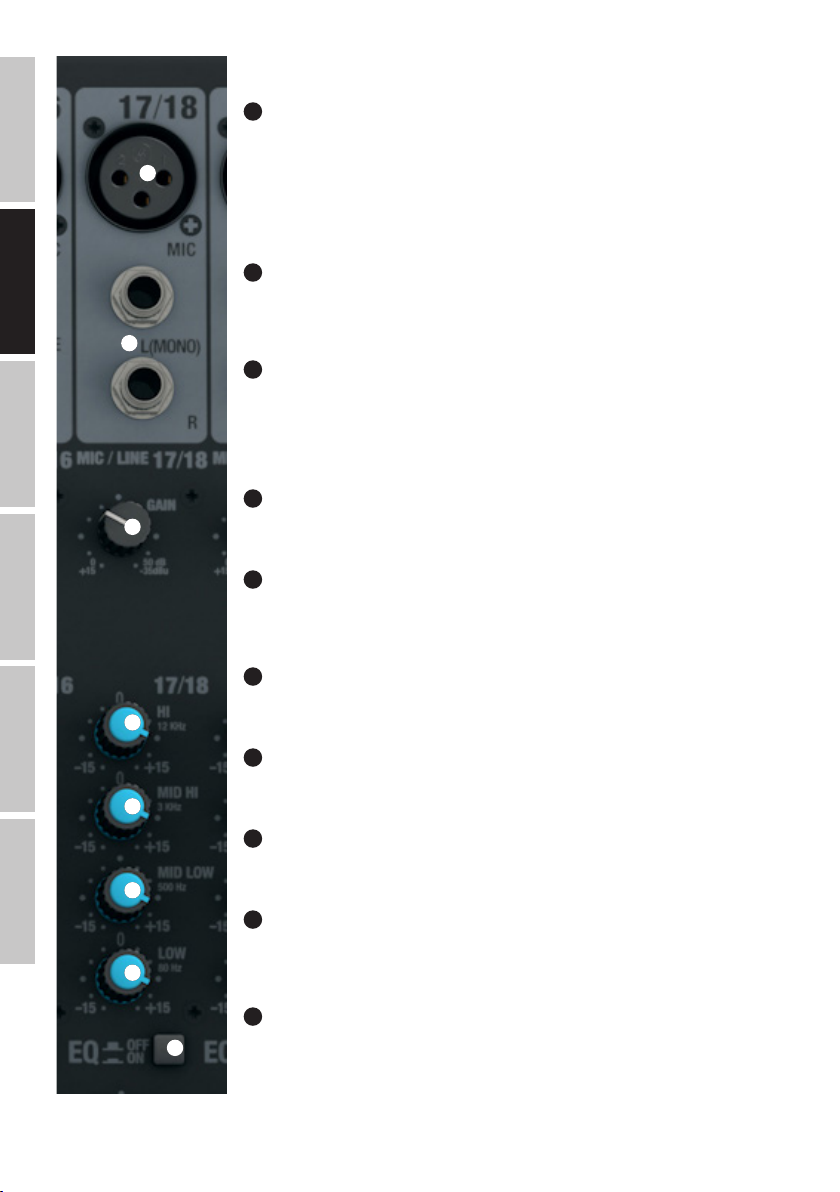
ENGLISH
DEUTSCHFRANCAIS
ESPAÑOL
STEREO-KANÄLE 17/18 & 19/20
39
MIC KANAL 17/18 & 19/20
Symmetrische Eingänge der Kanäle 17/18 und 19/20 mit 3-Pol XLR-Buchsen zum Anschließen von
Mikrofonen. Die Kanäle 17/18 und 19/20 können je nach Belegung sowohl als Mono- als auch als Stereo-
39
40
41
Kanäle verwendet werden (XLR und Klinke L IN = Mono / Klinke L und R IN = Stereo). Für den Betrieb von
Kondensator-Mikrofonen steht eine 48V Phantomspeisung zur Verfügung, die zentral auf die XLR-Buchsen
zugeschaltet werden kann (Nr. 3). Vor dem Ein- bzw. Ausstecken von Mikrofonen stellen Sie den Gain-Regler
(Nr. 41) bitte auf ein Minimum (Linksanschlag) und schalten die Phantomspeisung erst nach dem Anschließen
eines Mikrofons ein, bzw. vor dem Ausstecken aus.
40
LINE IN L/R KANAL 17/18 & 19/20
Unsymmetrische Eingänge der Stereo-Kanäle 17/18 & 19/20 mit 6,3mm Klinken-Buchsen zum Anschließen
von Zuspielgeräten mit Line-Pegel (z.B. Keyboard). Wird lediglich die Eingangsbuchse links (L) belegt, wird der
Kanal Mono betrieben.
41
GAIN KANAL 17/18 & 19/20
Justieren der Vorverstärkung des Mikrofon-Eingangs von 0 bis 50 dB, bzw. der Empfindlichkeit des LineEingangs von +15 bis -35 dBu. Stellen Sie den Gain-Regler so ein, dass die Clip-LED des entsprechenden
Kanals nur bei Pegelspitzen des anliegenden Signals kurz aufleuchtet. Vermeiden Sie permanentes Leuchten
der Clip-LED durch Reduzierung der Eingangsvorverstärkung, bzw. der Eingangsempfindlichkeit, reduzieren
Sie ggf. die Lautstärke des Zuspielgeräts.
42
EQUALIZER HI KANAL 17/18 & 19/20
Equalizer Höhenband für die Kanäle 17/18 und 19/20 (12kHz, +/-15 dB). Nach links gedreht werden Höhen
abgesenkt, nach rechts gedreht angehoben. In Mittelstellung (Rastpunkt) ist der Equalizer inaktiv.
43
EQUALIZER MID HI KANAL 17/18 & 19/20
Equalizer Mittenband HI für die Kanäle 17/18 und 19/20 (3kHz, +/-15 dB). Nach links gedreht werden die
hohen Mitten abgesenkt, nach rechts gedreht angehoben. In Mittelstellung (Rastpunkt) ist der Equalizer
inaktiv.
ITALIANO POLSKI
28
44
EQUALIZER MID LOW KANAL 17/18 & 19/20
Equalizer Mittenband LOW für die Kanäle 17/18 und 19/20 (500Hz, +/-15 dB). Nach links gedreht werden die
42
43
44
45
46
tiefen Mitten abgesenkt, nach rechts gedreht angehoben. In Mittelstellung (Rastpunkt) ist der Equalizer inaktiv.
45
EQUALIZER LOW KANAL 17/18 & 19/20
Equalizer Bassband für die Kanäle 17/18 und 19/20 (80Hz, +/-15 dB). Nach links gedreht werden Bässe
abgesenkt, nach rechts gedreht angehoben. In Mittelstellung (Rastpunkt) ist der Equalizer inaktiv.
46
EQ ON / OFF KANAL 17/18 & 19/20
Schalter zum Ein- und Ausschalten des Equalizers (HI, MID HI, MID LOW und LOW). In heruntergedrückter
Position ist der Equalizer aktiviert, in nicht heruntergedrückter Position deaktiviert.
47
AUX 1 + AUX 2 KANAL 17/18 & 19/20
Pegelsteller für die Zumischung des Signals von Kanal 17/18 und 19/20 auf externe Effektgeräte (Effekt Send,
Schalter Nr. 48 POST), oder für die Ansteuerung aktiver Bühnenmonitore (Monitor Send, Schalter Nr. 48 PRE).
Verwenden Sie die Line-Ausgänge AUX SEND 1 und 2 (Nr. 12) zur Ansteuerung.
48
AUX 1 + AUX 2 PRE/POST KANAL 17/18 & 19/20
Wenn Sie AUX 1 bzw. AUX 2 zur Ansteuerung eines externen Effektgeräts verwenden, bringen Sie den Schalter in die heruntergedrückte Position POST. Das Ansteuerungsignal wird nun hinter dem Kanal-Pegelsteller (Nr.
53) abgegriffen, ist also abhängig davon. Zur Ansteuerung eines Bühnenmonitors, bringen Sie den Schalter in
die nicht heruntergedrückte Position PRE. Das Signal wird nun vor dem Kanal-Pegelsteller (Nr. 53) abgegriffen
und die Lautstärke des Bühnenmonitors kann unabhängig von der Kanal-Lautstärke eingestellt werden.
Page 29
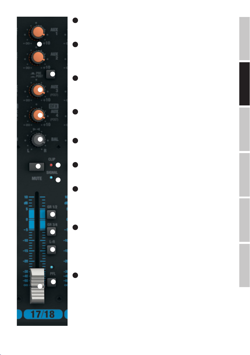
49
AUX 3 POST KANAL 17/18 & 19/20
Pegelsteller für die Zumischung des Signals von Kanal 17/18 und 19/20 auf ein externes Effektgeräte (Effekt
Send, Post Fader). Verwenden Sie den Line-Ausgang AUX SEND 3 (Nr. 12) zur Ansteuerung.
47
48
49
50
51
52
56
50
LEVEL DFX / AUX 4 POST KANAL 17/18 & 19/20
Pegelsteller für die Zumischung des Signals von Kanal 17/18 und 19/20 auf das interne digitale Effektgerät
(Effekt Send, Post Fader). Verwenden Sie den Line-Ausgang AUX SEND 4 (Nr. 12) zur Ansteuerung eines
externen Effektgeräts. Bei der Verwendung der AUX SEND 4-Klinkenbuchse, wird das interne Effektgerät
automatisch umgangen und ist somit nicht verwendbar.
51
BAL KANAL 17/18 & 19/20
Mit Hilfe des Balance-Reglers stellen Sie das Lautstärkenverhältnis zwischen dem linken und rechten Anteil
des anliegenden Stereo-Signals ein. Sobald die XLR-Buchse, bzw. lediglich die linke Buchse L (MONO) des
Line-Eingangs der Kanäle 17/18 und 19/20 belegt sind, erfüllt der Regler die Funktion eines PanoramaReglers.
52
MUTE KANAL 17/18 & 19/20
Um einen Kanal stummzuschalten, bringen Sie den MUTE-Schalter des entsprechenden Kanals in die
heruntergedrückte Position. Gleichzeitig beginnt die MUTE-LED des Schalters zu leuchten. Beim Deaktivieren
der Stummschaltung erlischt die MUTE-LED.
53
FADER KANAL 17/18 & 19/20
Pegelsteller für die Kanäle 17/18 und 19/20. Schieben Sie den Fader-Knopf nach oben, um die Lautstärke des
entsprechenden Kanals anzuheben und nach unten, um sie zu verringern.
54
55
54
SIGNAL-LED KANAL 17/18 & 19/20
Die Signal-LED leuchtet, sobald ein Audio-Signal am entsprechenden Kanal anliegt (abhängig von
Eingangspegel und Einstellung der Vorverstärkung, bzw. Eingangsempfindlichkeit - GAIN).
55
CLIP-LED KANAL 17/18 & 19/20
Sobald die rote Clip-LED aufleuchtet, wird der Eingang des entsprechenden Kanals an der Verzerrungsgrenze betrieben. Stellen Sie den Gain-Regler (Nr. 41) so ein, dass die Clip-LED nur bei Pegelspitzen des
anliegenden Signals kurz aufleuchtet. Vermeiden Sie permanentes Leuchten der Clip-LED durch Reduzierung
der Eingangsvorverstärkung, bzw. der Eingangsempfindlichkeit, reduzieren Sie ggf. die Lautstärke eines
Zuspielgeräts.
FRANCAISDEUTSCHENGLISH
56
57
58
59
53
GR 1/2 KANAL 17/18 & 19/20
Bringen Sie den GR 1/2-Schalter in die heruntergedrückte Position, um den entsprechenden Kanal zur Kanal-Gruppe 1 (BAL auf Linksanschlag), zur Kanal-Gruppe 2 (BAL auf Rechtsanschlag), oder mit den gleichen
Signalanteilen zu beiden Kanal-Gruppen 1 und 2 (BAL in Mittelstellung) hinzuzufügen. Gleichzeitig werden
die Signale der in eine Gruppe zusammengefassten Kanäle auf die entsprechenden Line-Ausgänge GROUP
OUT 1/2 geroutet. Die Gesamtlautstärke der so gebildeten Gruppe wird mit Hilfe des Pegelstellers GROUP 1/2
(Nr. 104) eingestellt, sollen die Audio-Signale der Gruppe auf den Summen-Kanal MAIN MIX geroutet werden,
bringen Sie den Schalter L-R (Nr.105) in die heruntergedrückte Position.
57
GR 3/4 KANAL 17/18 & 19/20
Bringen Sie den GR 3/4-Schalter in die heruntergedrückte Position, um den entsprechenden Kanal zur Kanal-Gruppe 3 (BAL auf Linksanschlag), zur Kanal-Gruppe 4 (BAL auf Rechtsanschlag), oder mit den gleichen
Signalanteilen zu beiden Kanal-Gruppen 3 und 4 (BAL in Mittelstellung) hinzuzufügen. Gleichzeitig werden
die Signale der in eine Gruppe zusammengefassten Kanäle auf die entsprechenden Line-Ausgänge GROUP
OUT 3/4 geroutet. Die Gesamtlautstärke der so gebildeten Gruppe wird mit Hilfe des Pegelstellers GROUP 3/4
(Nr. 106) eingestellt, sollen die Audio-Signale der Gruppe auf den Summen-Kanal MAIN MIX geroutet werden,
bringen Sie den Schalter L-R (Nr.107) in die heruntergedrückte Position.
ITALIANOPOLSKIESPAÑOL
29
Page 30
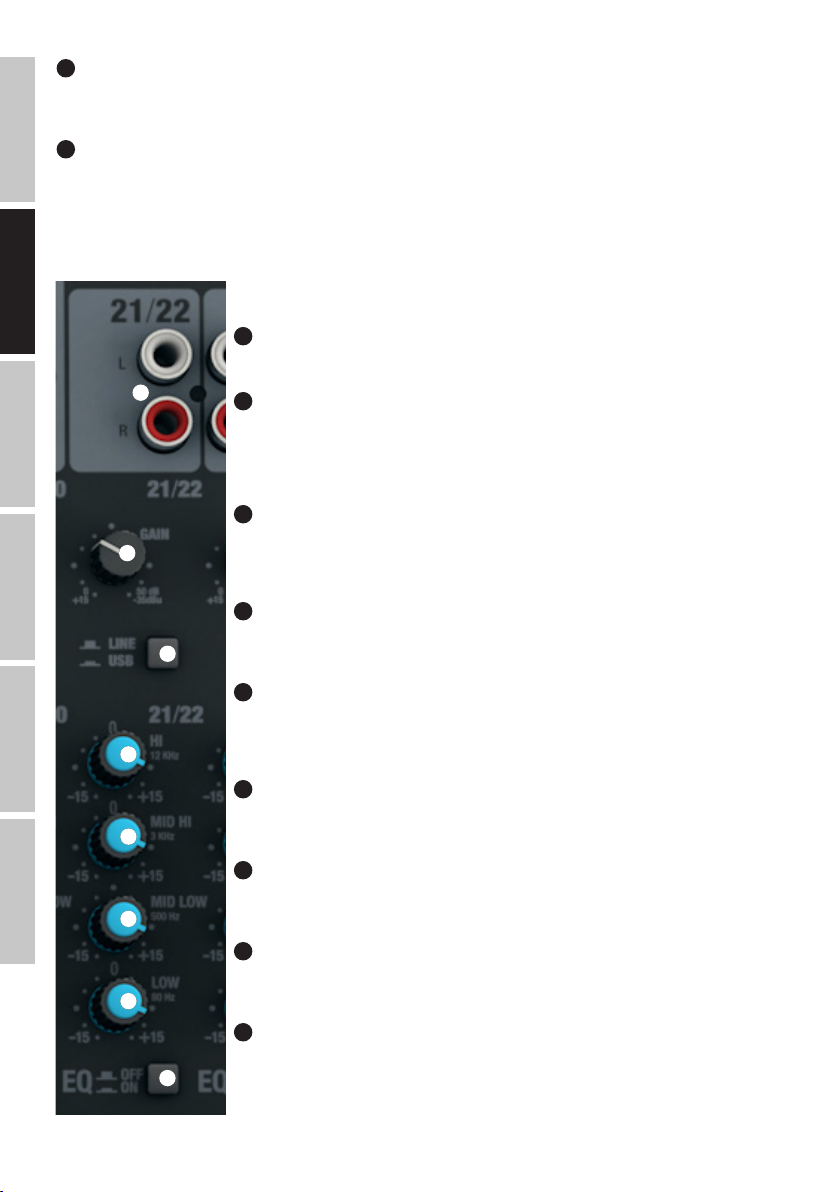
58
L-R KANAL 17/18 & 19/20
Um einen Eingangskanal (Kanal 17/18 und 19/20) direkt auf den Summen-Kanal MAIN MIX zu routen, bringen Sie den Schalter L-R des entsprechenden Kanals in die heruntergedrückte Position.
59
PFL KANAL 17/18 & 19/20
ENGLISH
Bringen Sie den PFL-Schalter (Pre Fader Listening) in die heruntergedrückte Position, erstens, um das Signal des entsprechenden Kanals
unabhängig vom Kanal-Pegelsteller (Nr. 53) mit Hilfe eines am Kopfhörer-Ausgang PHONES (Nr. 82) angeschlossenen Kopfhörers separat vorhören
zu können, zweitens, um eine genauere Gain-Einstellung vornehmen zu können, da der Pegel des Eingangs-Signals nun auf der 12-Segment
LED Pegel-Anzeige des Summen-Kanals MAIN MIX angezeigt wird. Gleichzeitig beginnt die PFL-LED des entsprechenden Kanals und die PFL-LED
unterhalb der Pegel-Anzeige des Summen-Kanals MAIN MIX zu leuchten. Wird der PFL-Schalter in die Ursprungsposition gebracht, erlöschen die
PFL-LEDs.
STEREO-KANÄLE 21/22 & 23/24
DEUTSCHFRANCAIS
60
LINE IN L/R KANAL 21/22 & 23/24
Unsymmetrische Line-Eingänge mit Cinch-Buchsen L und R.
60
61
ESPAÑOL
62
61
GAIN KANAL 21/22 & 23/24
Justieren der Empfindlichkeit des Line-Eingangs von +15 bis -35 dBu. Stellen Sie den Gain-Regler so ein,
dass die Clip-LED des entsprechenden Kanals nur bei Pegelspitzen des anliegenden Signals kurz aufleuchtet.
Vermeiden Sie permanentes Leuchten der Clip-LED durch Reduzierung der Eingangsempfindlichkeit, reduzieren Sie ggf. die Lautstärke des Zuspielgeräts.
62
LINE/USB 21/22
Umschalten der Signal-Quelle für den Stereo-Kanal 21/22. In nicht heruntergedrückter Position sind die
Cinch-Buchsen als Signal-Quelle aktiviert, in heruntergedrückter Position die USB-Schnittstelle auf der
Rückseite des Mischpults.
63
EQUALIZER HI KANAL 21/22 & 23/24
Equalizer Höhenband für die Kanäle 21/22 und 23/24 (12kHz, +/-15 dB). Nach links gedreht werden Höhen
abgesenkt, nach rechts gedreht angehoben. In Mittelstellung (Rastpunkt) ist der Equalizer inaktiv.
ITALIANO POLSKI
30
64
EQUALIZER MID HI KANAL 21/22 & 23/24
Equalizer Mittenband HIGH für die Kanäle 21/22 und 23/24 (3kHz, +/-15 dB). Nach links gedreht werden
die hohen Mitten abgesenkt, nach rechts gedreht angehoben. In Mittelstellung (Rastpunkt) ist der Equalizer
63
64
65
66
67
inaktiv.
65
EQUALIZER MID LOW KANAL 21/22 & 23/24
Equalizer Mittenband LOW für die Kanäle 21/22 und 23/24 (500Hz, +/-15 dB). Nach links gedreht werden die
tiefen Mitten abgesenkt, nach rechts gedreht angehoben. In Mittelstellung (Rastpunkt) ist der Equalizer inaktiv.
66
EQUALIZER LOW KANAL 21/22 & 23/24
Equalizer Bassband für die Kanäle 21/22 und 23/24 (80Hz, +/-15 dB). Nach links gedreht werden Bässe
abgesenkt, nach rechts gedreht angehoben. In Mittelstellung (Rastpunkt) ist der Equalizer inaktiv.
67
EQ ON/OFF KANAL 21/22 & 23/24
Schalter zum Ein- und Ausschalten des Equalizers (HI, MID HI, MID LOW und LOW). In heruntergedrückter
Position ist der Equalizer aktiviert, in nicht heruntergedrückter Position deaktiviert.
68
AUX 1 + AUX 2 KANAL 21/22 & 23/24
Pegelsteller für die Zumischung des Signals von Kanal 21/22 und 23/24 auf externe Effektgeräte (Effekt Send,
Schalter Nr. 69 POST), oder für die Ansteuerung aktiver Bühnenmonitore (Monitor Send, Schalter Nr. 69 PRE).
Verwenden Sie die Line-Ausgänge AUX SEND 1 und 2 (Nr. 12) zur Ansteuerung.
Page 31
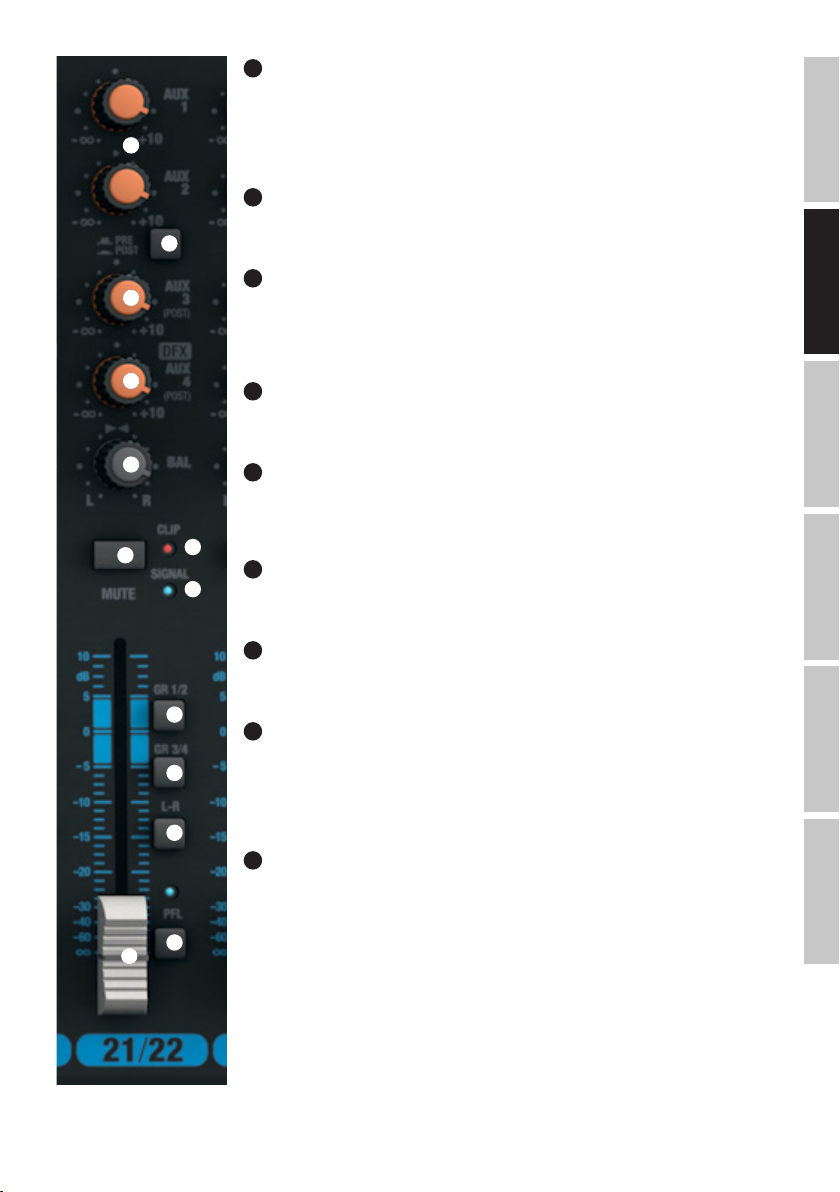
69
AUX 1 + AUX 2 PRE/POST KANAL 21/22 & 23/24
Wenn Sie AUX 1 bzw. AUX 2 zur Ansteuerung eines externen Effektgeräts verwenden, bringen Sie den Schalter in die heruntergedrückte Position POST. Das Ansteuerungsignal wird nun hinter dem Kanal-Pegelsteller (Nr.
74) abgegriffen, ist also abhängig davon. Zur Ansteuerung eines Bühnenmonitors, bringen Sie den Schalter in
68
69
70
71
72
73
die nicht heruntergedrückte Position PRE. Das Signal wird nun vor dem Kanal-Pegelsteller (Nr. 74) abgegriffen
und die Lautstärke des Bühnenmonitors kann unabhängig von der Kanal-Lautstärke eingestellt werden.
70
AUX 3 POST KANAL 21/22 & 23/24
Pegelsteller für die Zumischung des Signals von Kanal 21/22 und 23/24 auf ein externes Effektgeräte (Effekt
Send, Post Fader). Verwenden Sie den Line-Ausgang AUX SEND 3 (Nr. 12) zur Ansteuerung.
71
LEVEL DFX / AUX 4 POST KANAL 21/22 & 23/24
Pegelsteller für die Zumischung des Signals von Kanal 21/22 und 23/24 auf das interne digitale Effektgerät
(Effekt Send, Post Fader). Verwenden Sie den Line-Ausgang AUX SEND 4 (Nr. 12) zur Ansteuerung eines
externen Effektgeräts. Bei der Verwendung der AUX SEND 4-Klinkenbuchse, wird das interne Effektgerät
automatisch umgangen und ist somit nicht verwendbar.
72
BAL KANAL 21/22 & 23/24
Mit Hilfe des Balance-Reglers stellen Sie das Lautstärkenverhältnis zwischen dem linken und rechten Anteil
des anliegenden Stereo-Signals ein.
73
MUTE KANAL 21/22 & 23/24
Um einen Kanal stummzuschalten, bringen Sie den MUTE-Schalter des entsprechenden Kanals in die
heruntergedrückte Position. Gleichzeitig beginnt die MUTE-LED des Schalters zu leuchten. Beim Deaktivieren
der Stummschaltung erlischt die MUTE-LED.
76
74
75
FADER KANAL 21/22 & 23/24
Pegelsteller für die Kanäle 21/22 und 23/24. Schieben Sie den Fader-Knopf nach oben, um die Lautstärke des
entsprechenden Kanals anzuheben und nach unten, um sie zu verringern.
FRANCAISDEUTSCHENGLISH
75
SIGNAL-LED KANAL 21/22 & 23/24
Die Signal-LED leuchtet, sobald ein Audio-Signal am entsprechenden Kanal anliegt (abhängig von Eingangspegel und Einstellung der Vorverstärkung, bzw. Eingangsempfindlichkeit - GAIN).
77
78
79
80
74
76
CLIP-LED KANAL 21/22 & 23/24
Sobald die rote Clip-LED aufleuchtet, wird der Eingang des entsprechenden Kanals an der Verzerrungsgrenze betrieben. Stellen Sie den Gain-Regler (Nr. 61) so ein, dass die Clip-LED nur bei Pegelspitzen des
anliegenden Signals kurz aufleuchtet. Vermeiden Sie permanentes Leuchten der Clip-LED durch Reduzierung
der Eingangsvorverstärkung, bzw. der Eingangsempfindlichkeit, reduzieren Sie ggf. die Lautstärke eines
Zuspielgeräts.
77
GR 1/2 KANAL 21/22 & 23/24
Bringen Sie den GR 1/2-Schalter in die heruntergedrückte Position, um den entsprechenden Kanal zur Kanal-Gruppe 1 (BAL auf Linksanschlag), zur Kanal-Gruppe 2 (BAL auf Rechtsanschlag), oder mit den gleichen
Signalanteilen zu beiden Kanal-Gruppen 1 und 2 (BAL in Mittelstellung) hinzuzufügen. Gleichzeitig werden
die Signale der in eine Gruppe zusammengefassten Kanäle auf die entsprechenden Line-Ausgänge GROUP
OUT 1/2 geroutet. Die Gesamtlautstärke der so gebildeten Gruppe wird mit Hilfe des Pegelstellers GROUP 1/2
(Nr. 104) eingestellt, sollen die Audio-Signale der Gruppe auf den Summen-Kanal MAIN MIX geroutet werden,
bringen Sie den Schalter L-R (Nr. 105) in die heruntergedrückte Position.
ITALIANOPOLSKIESPAÑOL
31
Page 32

78
GR 3/4 KANAL 21/22 & 23/24
Bringen Sie den GR 3/4-Schalter in die heruntergedrückte Position, um den entsprechenden Kanal zur Kanal-Gruppe 3 (BAL auf Linksanschlag), zur
Kanal-Gruppe 4 (BAL auf Rechtsanschlag), oder mit den gleichen Signalanteilen zu beiden Kanal-Gruppen 3 und 4 (BAL in Mittelstellung)
hinzuzufügen. Gleichzeitig werden die Signale der in eine Gruppe zusammengefassten Kanäle auf die entsprechenden Line-Ausgänge GROUP OUT
3/4 geroutet. Die Gesamtlautstärke der so gebildeten Gruppe wird mit Hilfe des Pegelstellers GROUP 3/4 (Nr. 106) eingestellt, sollen die AudioSignale der Gruppe auf den Summen-Kanal MAIN MIX geroutet werden, bringen Sie den Schalter L-R (Nr. 107) in die heruntergedrückte Position.
ENGLISH
79
L-R KANAL 21/22 & 23/24
Um einen Eingangskanal (Kanal 21/22 und 23/24) direkt auf den Summen-Kanal MAIN MIX zu routen, bringen Sie den Schalter L-R des
entsprechenden Kanals in die heruntergedrückte Position.
80
PFL KANAL 21/22 & 23/24
Bringen Sie den PFL-Schalter (Pre Fader Listening) in die heruntergedrückte Position, erstens, um das Signal des entsprechenden Kanals
DEUTSCHFRANCAIS
unabhängig vom Kanal-Pegelsteller (Nr. 74) mit Hilfe eines am Kopfhörer-Ausgang PHONES (Nr. 82) angeschlossenen Kopfhörers separat vorhören
zu können, zweitens, um eine genauere Gain-Einstellung vornehmen zu können, da der Pegel des Eingangs-Signals nun auf der 12-Segment
LED Pegel-Anzeige des Summen-Kanals MAIN MIX angezeigt wird (Reduzieren des Pegels des Eingangs-Signals bei aufleuchtender CLIP-LED am
entsprechenden GAIN-Regler). Gleichzeitig beginnt die PFL-LED des entsprechenden Kanals und die PFL-LED unterhalb der Pegel-Anzeige des
Summen-Kanals MAIN MIX zu leuchten. Wird der PFL-Schalter in die Ursprungsposition gebracht, erlöschen die PFL-LEDs.
ESPAÑOL
ITALIANO POLSKI
32
Page 33
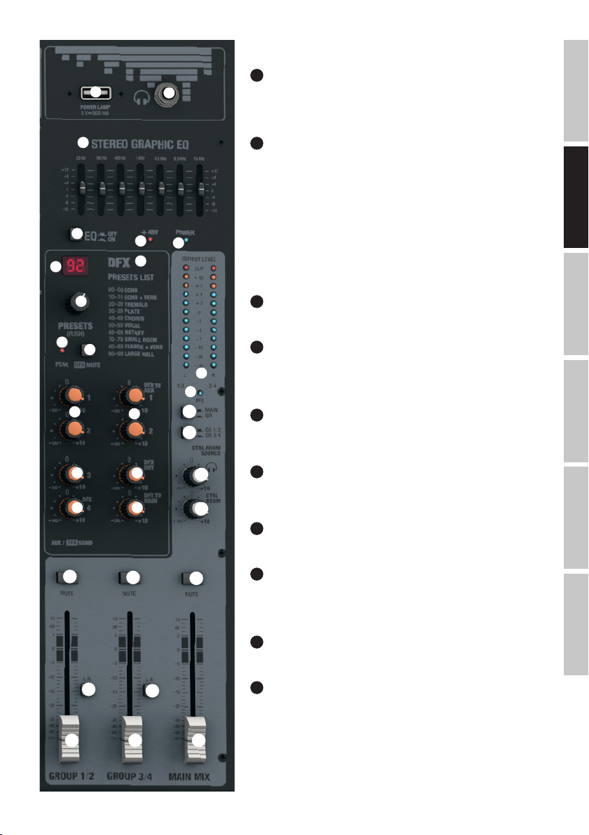
MASTER-SEKTION
81
POWER LAMP
81
82
USB-Buchse Typ A zum Anschließen einer Pult-Lampe. Achten Sie darauf, dass
die Spezifikationen des Anschlusses und der Pult-Lampe übereinstimmen (5V DC,
maximal 500mA).
83
84
87
88
90
91
92
93 95
94 97
82
KOPFHÖRERAUSGANG
6,3mm Stereo-Klinkenbuchse zum Anschließen eines Kopfhörers. Dieser Anschluss
ermöglicht das Wahlweise Abhören verschiedener Signale:
A. Schalter Nr. 100 (CTRL ROOM SOURCE MAIN/GR) nicht heruntergedrückt und kein
PFL-Schalter heruntergedrückt: Summen-Signal MAIN MIX.
B. Schalter Nr. 100 heruntergedrückt und kein PFL-Schalter heruntergedrückt:
Gruppen-Signal GROUP GR 1/2, oder GR 3/4 (Schalter Nr. 101 GR 1/2 / GR 3/4
85
86
89
beachten).
C. Einer, oder mehrere der PFL-Schalter der Eingangs-Kanäle heruntergedrückt:
Entsprechender/entsprechende Kanal/Kanäle vor dem Kanal-Pegelsteller abgegriffen
(Pre Fader Listening).
83
STEREO GRAPHIC EQ
FRANCAISDEUTSCHENGLISH
Grafischer 7-Band Equalizer für das Summen-Signal MAIN MIX.
84
EQ ON/OFF
98
99
95
100
101
103
Schalter zum Ein- und Ausschalten des Summen-Equalizers (Nr. 83).
In heruntergedrückter Position ist der Equalizer aktiviert, in nicht heruntergedrückter
Position deaktiviert.
85
ANZEIGE-LED +48V
Sobald die Phantomspeisung des Mischpults eingeschaltet wird, leuchtet die
Anzeige-LED +48V (Schalter Nr. 3 auf der Rückseite).
86
POWER-LED
Die Power-LED leuchte, sobald das Mischpult eingeschaltet und korrekt am Stromnetz
102
angeschlossen ist.
87
DISPLAY DFX PRESET
2-stelliges LED-Display zum Anzeigen der Effekt-Preset-Nummer (00 - 99).
108
105
104 106 110
109
107
111
88
DFX PRESETS (PUSH)
Dreh-Drück-Geber zum Auswählen und aktivieren der Effekt-Presets. Wählen Sie das
gewünschte Preset durch Drehen des Gebers an und aktivieren es durch Drücken auf
den Geber.
89
DFX PRESETS LIST
Liste der verfügbaren digitalen Effekte.
90
DFX PEAK-LED
Sobald die rote Peak-LED aufleuchtet, wird der Eingang des internen Effektgeräts an
der Verzerrungsgrenze betrieben. Stellen Sie den Effekt-Send-Pegelsteller DFX SEND
AUX 4 (Nr. 94) so ein, dass die Peak-LED auch bei Pegelspitzen des anliegenden
Signals nicht aufleuchtet.
ITALIANOPOLSKIESPAÑOL
33
Page 34

91
DFX MUTE
Um das interne Effektgerät stummzuschalten, drücken Sie kurz auf den DFX Mute-Taster und nochmals, um die Stummschaltung zu deaktivieren.
Ist das Effektgerät stummgeschaltet, leuchtet die Peak-LED Nr. 90 permanent.
92
SEND AUX 1 & AUX 2
ENGLISH
Pegelsteller für das Gesamt-Signal der über die AUX 1 und AUX 2 Pegelsteller ausgespielten Signale der Eingangskanäle 1 bis 23/24.
93
SEND AUX 3
Pegelsteller für das Gesamt-Signal der über die AUX 3 Pegelsteller ausgespielten Signale der Eingangskanäle 1 bis 23/24.
94
SEND AUX 4 / DFX
Pegelsteller für das Gesamt-Signal der über die AUX 4 / DFX Pegelsteller ausgespielten Signale der Eingangskanäle 1 bis 23/24 (extern, oder
DEUTSCHFRANCAIS
internes Effekgerät).
95
DFX TO AUX 1 & AUX 2
Pegelsteller für die Zumischung des Effekt-Signals des internen Effektgeräts auf die Ausspielwege AUX 1 und AUX 2.
96
DFX OUT
Pegelsteller für die Lautstärke des am Ausgang DFX OUT anliegenden Effekt-Signals.
97
DFX TO MAIN
Pegelsteller für die Zumischung des Effekt-Signals des internen Effektgeräts auf den Summen-Kanal MAIN MIX.
98
OUTPUT LEVEL
2x 12-Segment LED-Pegel-Anzeige für die Visualisierung des Pegels im Stereo-Summenkanal MAIN MIX und um eine genauere Gain-Einstellung
vornehmen zu können, da der Pegel eines Eingangs-Signals auf der LED Pegel-Anzeige angezeigt wird, sobald der PFL-Schalter des
entsprechenden Kanals gedrückt wird. Um Verzerrungen zu vermeiden, reduzieren Sie den Ausgangspegel am Pegelsteller MAIN MIX (Nr. 110), bzw.
ESPAÑOL
reduzieren Sie den Pegel des Eingangs-Signals am entsprechenden GAIN-Regler, sobald die rote CLIP-LED aufleuchtet.
99
PFL-LED
Die PFL-LED leuchtet auf, sobald einer (oder mehrere) der PFL-Schalter der Eingangs-Kanäle 1 bis 23/24 heruntergedrückt wird.
100
CTRL ROOM SOURCE MAIN / GR
Umschalter für die Wahl der Signal-Quelle für den Signal-Ausgang CTRL ROOM (Nr. 10) und den Kopfhörerausgang (Nr. 82). In nicht heruntergedrückter Position liegt das Summen-Signal MAIN MIX an, in heruntergedrückter Position das Gruppen-Signal GR1/2, oder GR3/4 (Schalter Nr. 101
GR 1/2 / GR 3/4 beachten).
101
CTRL ROOM SOURCE GR1/2 / GR3/4
Ist der Umschalter CTRL ROOM SOURCE MAIN / GR (Nr. 100) heruntergedrückt, kann als Signal-Quelle entweder das Gruppen-Signal GR1/2, oder
GR3/4 angewählt werden (Schalter nicht heruntergedrückt = GR1/2, Schalter heruntergedrückt = GR3/4)
102
CTRL ROOM LEVEL
ITALIANO POLSKI
Pegelsteller für den Stereo-Line-Ausgang CTRL ROOM (Nr. 10). Stellen Sie vor dem Einschalten eines angeschlossenen Abhör-Monitors den
Pegelsteller auf Minimum.
103
KOPFHÖRER LEVEL
Pegelsteller für den Kopfhörerausgang (Nr. 82). Verwenden Sie Kopfhörer mit einer minimalen Impedanz von 30 Ohm und achten darauf, die
Lautstärke auf einem angenehmen Pegel zu halten, um Gehörschäden durch laute Geräusche zu vermeiden. Stellen Sie vor dem Anschließen eines
Kopfhörers den Pegelsteller auf Minimum.
34
Page 35

104
GROUP 1/2
Pegelsteller für die Line-Ausgänge GROUP OUT 1 und 2 (Nr. 11) und für die Zumischung des Gruppen-Signals GROUP 1/2 zum Summen-Kanal
MAIN MIX, wenn Schalter GROUP 1/2 L-R heruntergedrückt ist (Nr. 105). Stellen Sie vor dem Einschalten einer angeschlossenen
Beschallungsanlage den Pegelsteller auf Minimum.
105
GROUP 1/2 L-R
Schalter zum Routen des Gruppen-Signals GROUP 1/2 auf den Summen-Kanal MAIN MIX (heruntergedrückte Position).
106
GROUP 3/4
Pegelsteller für die Line-Ausgänge GROUP OUT 3 und 4 (Nr. 11) und für die Zumischung des Gruppen-Signals GROUP 3/4 zum Summen-Kanal
MAIN MIX, wenn Schalter GROUP 3/4 L-R heruntergedrückt ist (Nr. 107). Stellen Sie vor dem Einschalten einer angeschlossenen
Beschallungsanlage den Pegelsteller auf Minimum.
107
GROUP 3/4 L-R
Schalter zum Routen des Gruppen-Signals GROUP 3/4 auf den Summen-Kanal MAIN MIX (heruntergedrückte Position).
108
GROUP 1/2 MUTE
Bringen Sie den Schalter in die heruntergedrückte Position, um das Gruppen-Signal GROUP 1/2 stummzuschalten. Gleichzeitig beginnt die
MUTE-LED des Schalters zu leuchten. Beim Deaktivieren der Stummschaltung erlischt die MUTE-LED.
109
GROUP 3/4 MUTE
Bringen Sie den Schalter in die heruntergedrückte Position, um das Gruppen-Signal GROUP 3/4 stummzuschalten. Gleichzeitig beginnt die
MUTE-LED des Schalters zu leuchten. Beim Deaktivieren der Stummschaltung erlischt die MUTE-LED.
110
MAIN MIX
Pegelsteller für die Stereo-Line-Ausgänge MAIN MIX OUTPUT Nr. 5 und Nr. 6. Schieben Sie den Fader-Knopf nach oben, um die Lautstärke
anzuheben und nach unten, um sie zu verringern. Stellen Sie vor dem Einschalten der angeschlossenen Beschallungsanlage den Pegelsteller auf
Minimum.
111
MAIN MIX MUTE
Bringen Sie den Schalter in die heruntergedrückte Position, um den Summen-Kanal MAIN MIX stummzuschalten. Gleichzeitig beginnt die MUTE-LED
des Schalters zu leuchten. Beim Deaktivieren der Stummschaltung erlischt die MUTE-LED.
INSTALLATION USB-SCHNITTSTELLE
Installation auf Windows Betriebssystemen (Windows XP® oder neuer):
Für die Installation sind keine Treiber-Downloads oder Treiber auf externen Speichermedien notwendig. Schließen Sie das Mischpult mit Hilfe des
mitgelieferten USB-Kabels an einer USB 2.0 Schnittstelle Ihres Computers an. Die Softwareinstallation erfolgt in den meisten Fällen automatisch.
Gegebenenfalls ist ein Neustart des Computers notwendig. In einigen Fällen erscheint ein Fenster (Gerätesoftwareinstallation), in dem Sie
aufgefordert werden, die Installation der USB Audio CODEC Software fertigzustellen. Folgen Sie dieser Aufforderung. Im Gerätemanager Ihres
Betriebssystems erscheint das Mischpult nun unter „Audio-, Video- und Gamecontroller“ als „USB Audio CODEC“, oder „USB-Audiogerät“ und ist
betriebsbereit. Je nach verwendeter Recording-Software kann es nötig sein, das Mischpult im Kontrollfeld „Sound“ („Systemsteuerung“→“Hard-
ware und Sound“ →“Sound“) als Aufnahme- und Wiedergabegerät auszuwählen.
Installation auf Apple Betriebssystemen (Mac OS X® 10.5 oder neuer):
Für die Installation sind keine Treiber-Downloads oder Treiber auf externen Speichermedien notwendig. Schließen Sie das Mischpult mit Hilfe des
mitgelieferten USB-Kabels an einer USB 2.0 Schnittstelle Ihres Computers an. Die Softwareinstallation erfolgt automatisch. Je nach verwendeter
Recording-Software kann es nötig sein, das Mischpult (USB Audio CODEC) im Kontrollfeld „Ton“ („Systemeinstellungen“→“Ton“) als Eingabe- und
Ausgabegerät auszuwählen.
FRANCAISDEUTSCHENGLISH
ITALIANOPOLSKIESPAÑOL
35
Page 36

TECHNISCHE DATEN
Modellbezeichnung: LDVIBZ24DC
Produktart: Analoges Mischpult
Typ: Live / Home recording
ENGLISH
Anzahl Kanäle: 24
Mono Kanäle:
Mono Mic/Line Eingangskanäle: 16
Mono Mic/Line Eingangsanschlüsse: 6,3 mm Stereoklinke, XLR
Mono Mic Eingangstyp: elektronisch symmetriert, diskreter Aufbau
Frequenzgang Mono Mic Eingang: 10 - 45.000Hz
Verstärkungsbereich Mono Mic Eingang: 50dB
Kanalübersprechung: 90 dB
DEUTSCHFRANCAIS
THD Mono Mic Eingang: 0.0058%
Impedanz Mono Mic Eingang: 4kOhm
S/N Ratio Mono Mic Eingang: 113dB
Mono Line Eingangstyp: elektronisch symmetriert, diskreter Aufbau
Verstärkungsbereich Mono Line Eingang: 50dB
THD Mono Line Eingang: 0.0045%
Impedanz Mono Line Eingang: 21k Ohm
S/N Ratio Mono Line Eingang: 116dB
Mono Kanal Equalizer Höhen: +/- 15dB @ 12kHz
Mono Kanal Equalizer Mitten: +/- 15dB @ 200Hz - 8kHz
Mono Kanal Equalizer Bässe: +/- 15dB @ 80Hz
Kanal-Insert: Kanal 1 - 8
Kanal-Insert Anschlüsse: 6,3 mm Stereoklinke (TIP= send / RING= return)
Phantomspeisung: +48V DC schaltbar auf XLR Inputs
ESPAÑOL
Low Cut: 95Hz
Hi-Z: Klinken-Eingang Kanal 1 - 4 schaltbar (>50kOhm)
Compressor: Kanal 1 - 8
Bedienelemente Kanal 1 - 16: Gain, Low Cut, High-Z (Kanäle 1 - 4), Compressor (Kanäle 1 - 8), EQ Hi, EQ Mid, EQ
Mid Freq, EQ Low, EQ on/off, DFX, AUX Send 1-2 pre (AUX2 pre/post switchable), AUX
Send 3-4 post, Channel Mute, Fader Routing switch (Group 1/2, Group 3/4, Main L+R),
Pan/Bal, Kanal-Fader, PFL switch
ITALIANO POLSKI
36
Page 37

Stereo Kanäle:
Stereo Line Eingangskanäle: 4
Stereo Line Eingangsanschlüsse: 2x 6,3 mm Stereoklinke (L mono, R) 2x RCA (Chinch)
Stereo Line Eingangstyp: Unbalanced
USB In/Out -Anschluß: USB-type B (Kanal 21/22)
Frequenzgang Stereo Line Eingang: 10 - 45.000Hz
Verstärkungsbereich Stereo Line Eingang: 50dB
Kanalübersprechung: 62 dB
THD Stereo Line Eingang: 0.0045%
Impedanz Stereo Line Eingang: 3,7kOhm
S/N Ratio Stereo Line Eingang: 116dB
Stereo Kanal Equalizer Höhen: +/- 15dB @ 12kHz
Stereo Kanal Equalizer hohe Mitten: +/- 15dB @ 3kHz
Stereo Kanal Equalizer tiefe Mitten: +/- 15dB @ 500Hz
Stereo Kanal Equalizer Bässe: +/- 15dB @ 80Hz
Bedienelemente Kanal 17/18 - 23/24: Gain, LINE/USB -switch (Kanal 21/22), EQ Hi, EQ Mid, EQ Mid Freq, EQ Low, EQ on/off,
Master-Sektion:
AUX/Effekt Send Kanäle: 4
AUX/Effekt Send Anschlüsse: 4x 6,3 mm Stereoklinke Unbalanced
Symmetrische Stereo Main-Ausgänge: 2
Symmetrische/unsymmetrische Stereo
Main-Ausgangsanschlüsse:
Impedanz symmetrische Stereo Main-Ausgänge: 120 Ohm
Max. Pegel symmetrische (unsymmetrische)
Stereo Main-Ausgänge:
Stereo Control Room Ausgänge: 1
Stereo Control Room Ausgangsanschlüsse: 2x 6,3 mm Klinke
Gruppen Ausgänge (GR OUT): 4
Gruppen Ausgangsanschlüsse: 4x 6,3 mm Klinke
Kopfhörerausgang: 1
Kopfhörerausgangsanschlüsse: 6,3 mm Stereoklinke
Minimale Kopfhörer-Impedanz: 30 Ohm
Digitaler Effektprozessor: Ja
Anzahl Presets: 100
Fußtasteranschluss DFX Mute: 6,3 mm Klinke (Fußtaster optional)
Bedienelemente Master-Sektion: 7-band graphic EQ, EQ On/Off, DFX Presets, DFX Mute, AUX/DFX Send 1 - 4, DFX to
DFX, AUX Send 1-2 pre (AUX2 pre/post switchable), AUX Send 3-4 post, Channel Mute,
Fader Routing switch (Group 1/2, Group 3/4, Main L+R), Bal, Kanal-Fader, PFL switch
2x 6,3 mm Stereoklinke, 2x XLR male
22dBu (20dBV)
Main, DFX to Aux, Phones, CTRL, GROUP to Main -switch, Phantom Power +48V, Main
Mix Fader, Group Fader, Power, CTRL Room Source MAIN/GR, GR1/2 - GR3/4, Group
Mute, Main Mute
FRANCAISDEUTSCHENGLISH
ITALIANOPOLSKIESPAÑOL
37
Page 38

Generelle Spezifikationen:
Anzeigeelemente: Kanal-CLIP, Kanal-Signal, Kanal-PFL, Effekt-CLIP, DFX LED-Display, Power, Phantom
Anschluss für Pultlampe: USB-A Buchse, 5VDC, max. 500mA
USB In/Out: USB 2.0, 16 Bit Delta-Sigma
ENGLISH
Stromversorgungsanschluss: IEC Netzbuchse
Betriebsspannung: 100 - 240 VAC 50/60Hz
Leistungsaufnahme (max.): 70W
Sicherung: T1,6AL / 250V
Nutzungstemperaturbereich: 0°C to +45°C
Nutzungsfeuchtigkeitsbereich: 10%rel - 80%rel, nicht kondesierend
DEUTSCHFRANCAIS
Breite: 712mm
Höhe: 80mm
Tiefe: 425mm
Gewicht: 9,36kg
Power, 2x 12-Segment Pegel-Anzeige, Mute-LEDs
DA: 32kHz, 44,1kHz, 48kHz
AD: 8kHz, 11,025kHz, 16kHz, 22,05kHz, 32kHz, 44,1kHz, 48kHz
HERSTELLERERKLÄRUNGEN
HERSTELLERGARANTIE & HAFTUNGSBESCHRÄNKUNG
Unsere aktuellen Garantiebedingungen und Haftungsbeschränkung finden Sie unter: http://www.adamhall.com/media/shop/downloads/
documents/manufacturersdeclarations.pdf. Im Service Fall wenden Sie sich bitte an Adam Hall GmbH, Daimlerstraße 9, 61267 Neu Anspach
/ E-Mail Info@adamhall.com / +49 (0)6081 / 9419-0. Die aktuelle Konformitätserklärung können Sie unter info@adamhall.com anfragen.
KORREKTE ENTSORGUNG DIESES PRODUKTS
(Gültig in der Europäischen Union und anderen europäischen Ländern mit Mülltrennung) Dieses Symbol auf dem Produkt oder
dazugehörigen Dokumenten weist darauf hin, dass das Gerät am Ende der Produktlebenszeit nicht zusammen mit dem normalen
Hausmüll entsorgt werden darf, um Umwelt- oder Personenschäden durch unkontrollierte Abfallentsorgung zu vermeiden. Bitte entsorgen
Sie dieses Produkt getrennt von anderen Abfällen und führen es zur Förderung nachhaltiger Wirtschaftskreisläufe dem Recycling zu. Als
ESPAÑOL
Privatkunde erhalten Sie Informationen zu umweltfreundlichen Entsorgungsmöglichkeiten über den Händler, bei dem das Produkt erworben
wurde, oder über die entsprechenden regionalen Behörden. Als gewerblicher Nutzer kontaktieren Sie bitte Ihren Lieferanten und prüfen
die ggf. vertraglich vereinbarten Konditionen zur Entsorgung der Geräte. Dieses Produkt darf nicht zusammen mit anderen gewerblichen
Abfällen entsorgt werden.
ITALIANO POLSKI
38
Page 39

FRANCAIS
VOUS AVEZ FAIT LE BON CHOIX!
Cet appareil a été développé et fabriqué en appliquant des exigences de qualité très élevées : il garantit des années de fonctionnement sans
problème. Grâce à de nombreuses années d‘expérience, LD Systems est un nom connu dans le domaine des produits audio haut de gamme. Veuillez lire attentivement ce Manuel Utilisateur : vous apprendrez rapidement à utiliser votre appareil LD Systems de façon optimale.
Pour plus d‘informations sur LD Systems, visitez notre site Web, WWW.LD-SYSTEMS.COM
MESURES PRÉVENTIVES
1. Veuillez lire attentivement ce manuel.
2. Rangez tous les documents d‘information et d‘instructions en lieu sûr.
3. Veuillez suivre toutes les instructions
4. Observez tous les messages d‘avertissement N‘enlevez pas de l‘appareil les étiquettes de sécurité ou autres informations.
5. N‘utilisez l‘appareil que pour des applications et de la façon appropriées.
6. Utilisez exclusivement des pieds et des dispositifs de fixation stables et adaptés lorsque l‘appareil est utilisé en installation fixe. Assurez-vous
que les fixations murales ont été montées correctement, et qu‘elles sont sécurisées. Vérifiez que l‘appareil est installé en toute sécurité, et qu‘il ne
peut pas tomber.
7. Lors de l‘installation, observez les règlementations de sécurité en vigueur dans votre pays.
8. N‘installez et n‘utilisez pas l‘appareil à proximité de radiateurs, d‘accumulateurs de chaleur, de fours ou de toute autre source de chaleur.
Vérifiez que l‘appareil est installé de façon à bénéficier en permanence d‘un refroidissement efficace et qu‘il ne peut pas chauffer de façon
excessive.
9. Ne placez aucune source de flamme sur l‘appareil – par exemple, une bougie allumée.
10. Ne bloquez pas les ouïes d‘aération.
11. Cet appareil a été exclusivement conçu pour une utilisation en intérieur. N‘utilisez pas l‘appareil à proximité immédiate d‘eau (à moins
qu‘il ne s‘agisse d‘un appareil conçu pour une utilisation en extérieur – dans ce cas, respectez les instructions correspondantes ci après) Ne
mettez pas l‘appareil en contact avec des matériaux, des liquides ou des gaz inflammables.
13. Vérifiez qu‘aucun petit objet ne puisse tomber à l‘intérieur de l‘appareil.
14. N‘utilisez avec cet appareil que des accessoires recommandés et approuvés par le fabricant.
15. N‘ouvrez pas l‘appareil, et n‘essayez pas de le modifier.
16. Lors du branchement de l‘appareil, sécurisez le passage du câble secteur, afin d‘éviter tout dommage ou accident, par exemple quelqu‘un qui trébuche sur le câble.
17. Lors du transport, vérifiez que l‘appareil ne peut tomber, ce qui pourrait provoquer des dommages matériels et/ou corporels.
18. Si votre appareil ne fonctionne plus correctement, que de l‘eau ou des objets ont pénétré à l‘intérieur, ou qu‘il a été endommagé de
quelque façon que ce soit, éteignez-le immédiatement et débranchez sa prise secteur (s‘il s‘agit d‘un appareil alimenté). Cet appareil ne
doit être réparé que par un personnel autorisé.
19. Pour le nettoyage de l‘appareil, utilisez un chiffon sec/
20. Observez toutes les réglementations en vigueur dans votre pays pour mettre l‘appareil au rebut. Lorsque vous jetez l‘emballage de
l‘appareil, veuillez séparer plastique, papier et carton.
21. Les films plastique doivent être mis hors de portée des enfants.
APPAREILS RELIÉS AU SECTEUR :
22. ATTENTION : Si le câble de l‘appareil est muni d‘un fil de terre, il doit être relié à une prise murale avec terre. Ne désactivez jamais la
mise à la terre d‘un appareil.
23. N‘allumez pas l‘appareil immédiatement s‘il a subi une grande différence de température ambiante (par exemple, lors du transport).
L‘humidité et la condensation pourraient l‘endommager. Ne mettez l‘appareil sous tension que lorsqu‘il est parvenu à la température de la
pièce.
24. Avant de relier l‘appareil à la prise murale, vérifiez que la valeur et la fréquence de tension secteur sur laquelle il est réglé
correspondent bien à la valeur et à la fréquence de la tension secteur locale. Si l‘appareil possède un sélecteur de tension, ne le branchez
sur la prise murale qu‘après avoir vérifié que la valeur réglée correspond à la valeur effective de la tension secteur. Si la fiche du cordon
secteur ou du bloc adaptateur livré avec votre appareil ne correspond pas au format de votre prise murale, veuillez consulter un électricien.
25. Ne piétinez pas le câble secteur. Assurez-vous que le câble secteur n‘est pas trop pincé, notamment au niveau de l‘arrière de l‘appareil
(ou de son adaptateur secteur) et de la prise murale.
26. Lors du branchement de l‘appareil, vérifiez que l‘accès au câble secteur ou au bloc adaptateur reste facile. Sortez la fiche secteur de la
prise murale dès que vous n‘utilisez pas l‘appareil pendant un certain temps, ou si vous désirez nettoyer l‘appareil. Pour ce faire, tirez toujours
sur la fiche elle-même, ou sur le bloc secteur lui-même ; ne tirez jamais sur le câble. Ne manipulez jamais le câble secteur ou l‘adaptateur
secteur avec des mains mouillées.
27. N‘éteignez/rallumez pas l‘appareil rapidement plusieurs fois de suite : vosu risquez de réduire la longévité de ses composants internes.
28. CONSEIL IMPORTANT : Ne remplacez le fusible que par un fusible de même type et du même calibre. Si le fusible fond de façon répétée,
veuillez consulter un centre de réparations agréé.
29. Pour séparer complètement l‘appareil du secteur, débranchez le cordon secteur ou l‘adaptateur de la prise murale.
30. Si votre appareil est muni d‘un connecteur secteur verrouillable (Volex), il faut d‘abord déverrouiller le mécanisme avant d‘enlever le
cordon secteur. Attention, lorsque vous retirez le câble secteur, à ne pas faire bouger l‘appareil, ce qui pourrait se traduire par un risque de
chute, de blesser quelqu‘un, ou tout autre dommage. Manipulez toujours le cordon secteur avec soin.
31. Débranchez la fiche secteur ou l‘adaptateur de la prise murale en cas d‘orage, ou si vous n‘utilisez pas l‘appareil pendant une longue
période.
FRANCAISDEUTSCHENGLISH
ITALIANOPOLSKIESPAÑOL
39
Page 40

32. L‘appareil ne doit pas être alimenté lors de son installation (cordon secteur non relié à la prise murale).
33. Poussière et autres dépôts à l‘intérieur de l‘appareil sont susceptibles de l‘endommager. Si les conditions environnementales sont
difficiles (présence de poussière, de nicotine, de gouttelettes d‘eau...), il est recommandé de le confier à un personnel spécialisé pour
entretien et nettoyage (non pris en charge par la garantie), afin d‘éviter toute surchauffe et défaillance.
34. Respectez une distance minimale de 0,5m par rapport à des matériaux inflammables.
35. Si vous désirez alimenter plusieurs projecteurs simultanément, les conducteurs du câble secteur doivent posséder une section minimale
ENGLISH
de 1,5 mm². Dans l’Union Européenne, les câbles électriques doivent être de type H05VV-F ou équivalent. Adam Hall propose des câbles
secteur adaptés. De tels câbles permettent d’alimenter plusieurs appareils par renvoi secteur de l’un à l’autre, Power Out vers Power In.
Assurez-vous que la consommation totale de tous les appareils connectés ne dépasse pas la valeur correspondante en ampères (A)
indiquée sur l’appareil. Essayez de maintenir les câbles secteur aussi courts que possible.
ATTENTION :
Ne démontez jamais le couvercle de l‘appareil, vous risquez de recevoir un choc électrique.
L‘appareil ne renferme aucune pièce ni composant réparable ou remplaçable par l‘utilisateur. Ne
confiez l‘entretien et la réparation qu‘à un personnel qualifié.
DEUTSCHFRANCAIS
ATTENTION ! NIVEAUX SONORES ÉLEVÉS SUR LES PRODUITS AUDIO
Cet appareil a été conçu en vue d‘une utilisation professionnelle. L‘utilisation commerciale de cet appareil est soumise aux réglementations
et directives en vigueur dans votre pays en matière de prévention d‘accident. En tant que fabricant, Adam Hall est tenu de vous avertir
formellement des risques relatifs à la santé. Risques provoqués par une exposition prolongée à des niveaux sonores élevés : Lors de
l‘utilisation de ce produit, il est possible d‘atteindre des niveaux de pression sonore (exprimés en dB SPL) élevés, susceptibles de provoquer
des dommages auditifs irréparables chez les artistes, les techniciens et le public. Évitez toute exposition prolongée à des niveaux de
pression sonore élevés (supérieurs à 90 dB SPL).
ESPAÑOL
ATTENTION ! CONSEILS IMPORTANTS POUR LES PRODUITS D‘ÉCLAIRAGE
1. Ce produit est conçu pour une utilisation professionnelle dans le domaine du spectacle vivant : il n‘est pas prévu pour une utilisation en
éclairage domestique.
2. Ne regardez jamais directement le faisceau lumineux, même brièvement.
3. Ne regardez jamais le faisceau lumineux par l‘intermédiaire d‘un appareil optique grossissant (jumelles par exemple).
4. Dans certaines circonstances, les effets Stroboscope sont susceptibles de provoquer des crises d‘épilepsie auprès de personnes
sensibles. Il est donc conseillé aux personnes épileptiques d‘éviter les lieux où sont installés des stroboscopes.
Le pictogramme en forme de triangle équilatéral contenant un éclair terminé d‘une flèche avertit l‘utilisateur de la présence
d‘une tension dangereuse à l‘intérieur de l‘appareil, tension susceptible de provoquer un choc électrique.
Le pictogramme en forme de triangle équilatéral renfermant un point d‘exclamation signale à l‘utilisateur la présence
d‘instructions importantes concernant l‘utilisation ou l‘entretien de l‘appareil.
ATTENTION ! Ce symbole correspond à des surfaces chaudes. En cours de fonctionnement, certaines parties de l’appareil
peuvent devenir chaudes. Après utilisation, ne manipulez ou ne transportez l’appareil qu’au bout de 10 minutes de
refroidissement.
INTRODUCTION
LDVIBZ24DC - Table de mixage 24 canaux avec multieffet numérique et compresseur
La VIBZ 24DC est une table de mixage d’une grande polyvalence, équipée de 16 entrées micro symétriques intégrant des préamplis de
haute qualité, un filtre passe-haut (Low-Cut), un égaliseur 3 bandes efficace avec médium semi-paramétrique et une alimentation fantôme
commutable. Deux autres peuvent aussi servir d’entrée stéréo au niveau ligne.
8 des voies micro possèdent un compresseur intégré, permettant de maîtriser la dynamique avec précision, pour un son plus efficace. Les
voies stéréo sont munies d’égaliseurs 4 bandes.
La section Master de la table de mixage gère notamment 2 départs/retours effets, et possède des sorties symétriques sur XLR, des sorties
ITALIANO POLSKI
Groupe et Monitor ainsi qu’une prise casque. La console VIBZ 24 DC possède de plus un port USB recevant des données audio depuis un
ordinateur, un multieffet numérique avec 100 presets et un connecteur pour lampe 5 volts.
Grâce à des détails d’équipement importants, comme la fonction PFL ou les touches Mute, et un son naturel et transparent, la VIBZ 24 DC
constitue un choix parfait pour les applications Live, l’installation fixe et les utilisations en home studio de haut niveau.
40
Page 41

GUIDE DE PRISE EN MAIN RAPIDE AVEC EXEMPLE DE CÂBLAGE
1. Vérifiez que la table de mixage et tous les appareils à lui connecter sont éteints.
2. Connectez les appareils à la table de mixage, à l’aide de câbles adaptés.
3. Réglez les préamplis de toutes les voies, ainsi que les réglages de volume des voies 1 à 23/24 et MAIN MIX à la valeur minimale. Réglez tous les
potentiomètres d’égaliseurs en position médiane (crantée). Réglez le niveau (volume sonore) au minimum sur les enceintes actives. N’activez la
tension fantôme (+48V) de la console de mixage que si vous utilisez un micro statique.
4. Allumez les appareils de votre installation selon l’ordre suivant : Microphone et claviers (ou autres sources audio), puis console de mixage, et
enfin les enceintes actives.
5. Réglez le potentiomètre Gain des voies mono de façon à ce que la LED Clip de la voie ne s’allume qu’occasionnellement sur les crêtes de signal.
Si la LED Clip s’allume de façon continue, réduisez le gain sur le préampli d’entrée.
6. Placez la touche L-R des voies utilisées en position enfoncée, et la touche MUTE en position non enfoncée, y compris la touche MUTE des
généraux MAIN MIX.
7. Amenez les faders (réglages de gain) des voies que vous utilisez et celui des généraux (MAIN MIX) jusqu’en position repérée «0 dB».
8. En présence des signaux audio (voix, chant, claviers...), montez le volume sur les enceintes actives jusqu’à obtenir le niveau sonore désiré.
9. Vous pouvez à présent, en fonction des signaux d’entrée, procéder au réglage fin du volume de chaque voie, des égaliseurs, des compresseurs et
des effets selon vos goûts.
CONSEIL: Pour éteindre les appareils de votre installation, procédez selon l’ordre suivant : Réglez tout d’abord le volume des enceintes actives au
minimum, puis éteignez-les ; vous pouvez ensuite éteindre la console de mixage puis les appareils qui lui sont connectés.
FRANCAISDEUTSCHENGLISH
Enceinte active Enceinte active
Retour actif
ITALIANOPOLSKIESPAÑOL
41
Page 42

CONNECTEURS, CONTRÔLES ET INDICATEURS
ENGLISH
Embase secteur au format IEC, avec porte-fusible intégré. Le câble secteur correspondant est livré.
CONSEIL IMPORTANT : Remplacez exclusivement le fusible par un fusible neuf du même format et du même calibre (valeurs indiquées sur le
panneau arrière de l’appareil). Si le fusible fond de façon répétée, veuillez consulter un centre de réparations agréé.
DEUTSCHFRANCAIS
Interrupteur On/Off pour la tension d’alimentation de l’appareil (ON = sous tension).
Tension d’alimentation fantôme 48 volts continue, permettant d’utiliser des microphones statiques haut de gamme. Placez le sélecteur en position
ON (la LED rouge n°85 s’allume) pour activer la tension d’alimentation fantôme sur les entrées micro XLR ; en position OFF (non enfoncée) pour la
désactiver (la LED rouge s’éteint). N’activez l’alimentation fantôme qu’après avoir branché le microphone, et désactivez-la avant de le débrancher.
Lors de ces phases, baissez à fond les faders des voies.
Port USB-B, pour connexion à un ordinateur sous macOS ou Windows (Windows XP à Windows 10, macOS, USB 2.0 en enregistrement et en
lecture)
ESPAÑOL
Sortie stéréo symétrique au niveau ligne, sur connecteurs XLR 3 points, pour connexion d’un système de sonorisation actif. Application : restitution
du signal mixé sur la console.
Sortie stéréo asymétrique au niveau ligne sur connecteurs jack 6,35 mm, pour connexion d’un système de sonorisation actif. Application : restitution
du signal mixé sur la console.
1
3
2
4
EMBASE SECTEUR ET PORTE-FUSIBLE
1
POWER ON/OFF
2
+48 V ON / OFF
3
USB IN/OUT
4
SORTIE MAIN MIX (BAL)
5
SORTIE MAIN MIX (UNBAL)
6
5
8
6 7
9
12
11
10
13
MAIN INSERT
7
Point d’insertion sur connecteur jack 6,35 mm 3 points, permettant de traiter le signal des généraux par l’intermédiaire d’un processeur externe
(compresseur, noise gate, égaliseur etc.). La connexion de cet appareil externe s’effectue via un câble spécifique, dit «en Y» (jack TRS vers 2 x jacks
mono ou 2 XLR). L’assignation des points du jack est la suivante : pointe = départ signal, anneau = retour signal, corps = masse.
DFX OUT
8
Jack 6,35 mm 3 points pour récupération du signal du multieffet
ITALIANO POLSKI
ENTRÉE FOOTSWITCH DFX MUTE
9
Jack 6,35 mm pour connexion d’une pédale de Footswitch (sélecteur au pied), afin de télécommander la fonction Mute du multieffet interne
(activation/désactivation).
CTRL ROOM
10
Sortie stéréo asymétrique au niveau ligne sur connecteurs jack 6,35 mm pour branchement d’enceintes actives etc. Sortie du signal des généraux,
ou des groupes 1-2 ou 3-4 de la console, ou du signal du bus d’écoute PFL (commutable).
42
Page 43
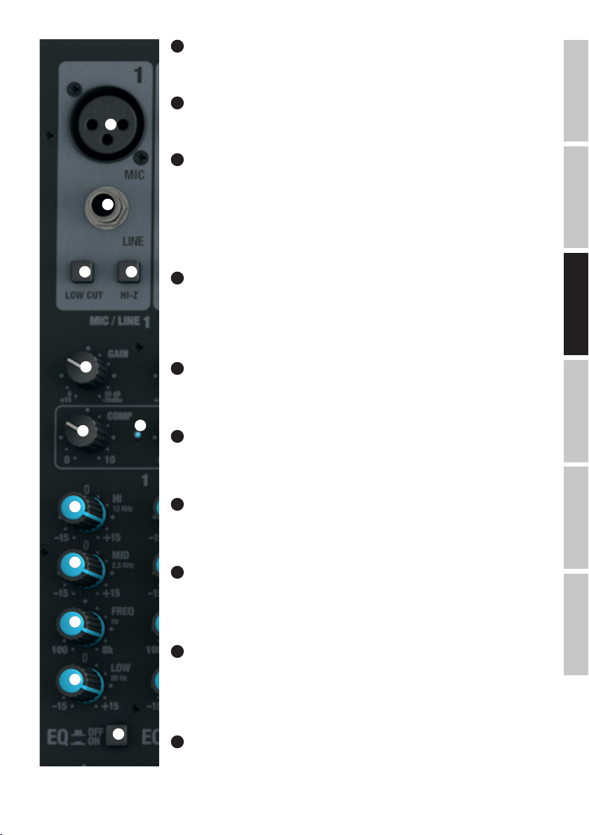
14
15
16 17
GROUP OUT 1-4
11
Sortie stéréo/double mono (groupes 1 et 2) asymétrique au niveau ligne sur connecteurs jack 6,35 mm, pour
connexion de retours de scène actifs etc. Sortie des signaux des groupes 1 à 4 de la console de mixage.
AUX SEND 1-4
12
Sorties mono ligne asymétriques sur jacks 6,35 mm pour connexion d’un multieffet externe (POST Fader) ou
de retours de scène actifs (PRE Fader).
INSERT CH1 - CH8
13
Point d’insertion sur connecteur jack 6,35 mm 3 points, permettant de traiter le signal de la voie correspondante 1 à 8 par l’intermédiaire d’un processeur externe (compresseur, noise gate, etc.). La connexion de cet
appareil externe s’effectue via un câble spécifique, dit «en Y» (jack TRS vers 2 x jacks mono ou 2 XLR).
L’assignation des points du jack est la suivante : pointe = départ signal, anneau = retour signal, corps =
masse.
ENTRÉES MONO 1-16
VOIES MICRO 1-16
14
Entrées mono symétriques pour les canaux 1 à 16, sur embases XLR 3 points pour connexion d’un
microphone. Une alimentation fantôme 48 volts est disponible pour utilisation de micros statiques ; elle
s’applique aux embases XLR simultanément (touche n°3). Avant de brancher/débrancher les microphones,
veuillez régler le potentiomètre Gain (n°18) au minimum, en le tournant à fond à gauche. Activez la tension
fantôme après connexion, et désactivez-la avant déconnexion.
FRANCAISDEUTSCHENGLISH
18
19
21
22
23
24
20
25
ENTRÉES LIGNE VOIE 1-16
15
Entrées mono symétriques pour les canaux 1 à 16, sur embase jack 6,35 mm, pour connexion d’une source
audio au niveau ligne. Avant de brancher/débrancher le câble jack, veuillez régler le potentiomètre Gain (n°18)
au minimum, en le tournant à fond à gauche.
FILTRE LOW CUT VOIES 1-16
16
Filtre passe-haut, atténuant les fréquences graves du signal. Le filtre LOW CUT s’utilise sur les voix parlées ou
chantées : une fois activé (touche enfoncée), il atténue les éventuels parasites dans le grave, ce qui améliore
l’intelligibilité. La fréquence charnière est de 95 Hz.
ENTRÉES HI-Z VOIES 1-4
17
Cette touche permet de faire passer individuellement les entrées jack des voies 1-4 en mode haute
impédance (touche enfoncée). Ce mode permet de connecter directement, sans boîtier de direct, une basse
ou une guitare électrique par exemple.
GAIN VOIES 1-16
18
Réglage de préamplification de l’entrée micro, gain de 0 à 50 dB, ou de la sensibilité de l’entrée ligne, de +15
à -35 dBu. Réglez le potentiomètre de gain de façon à ce que la LED Peak de la voie ne clignote
qu’occasionnellement. Évitez d’allumer la LED Peak de façon continue. Pour ce faire, réduisez le gain sur le
préampli micro (ou la sensibilité de l’entrée ligne).
COMP VOIES 1-8
19
Compresseur réglable, sur les voies 1 à 8. Selon le réglage, la dynamique du signal se trouve plus ou moins
réduite, ce qui améliore son «efficacité». Si le potentiomètre se trouve réglé à fond à gauche, le compresseur
est désactivé ; à fond à droite, l’intensité de la compression est maximale. À mesure que la compression
devient plus intense, une fonction de rattrapage compense automatiquement la réduction de niveau. Utilisez
le compresseur pour, par exemple, aider à «faire passer» une voix dans un mix.
LED COMP
20
Dès que le compresseur fonctionne, l’indicateur COMP s’allume.
ITALIANOPOLSKIESPAÑOL
43
Page 44

ENGLISH
DEUTSCHFRANCAIS
ESPAÑOL
21
ÉGALISEUR HI VOIES 1-16
Égaliseur d’aigus pour les voies 1 à 16 (fréquence centrale 12 kHz, +/-15 dB). Tourner vers la gauche pour
baisser les aigus, vers la droite pour les monter. En position centrale (crantée), le correcteur est inactif.
ÉGALISEUR MID VOIES 1-16
26
27
28
29
30
31
22
Égaliseur de médiums pour les voies 1 à 16 (fréquence centrale réglable, +/-15 dB). Tourner vers la gauche
pour baisser les médiums, vers la droite pour les monter. En position centrale (crantée), le correcteur est
inactif.
POTENTIOMÈTRE MID FREQ VOIES 1-16
23
Réglage de la fréquence centrale d’intervention de la bande médium. Ce potentiomètre permet de régler la
fréquence d’intervention sur la bande médium, entre 200 Hz et 8 kHz.
ÉGALISEUR LOW VOIES 1-16
24
Égaliseur de graves pour les voies 1 à 16 (fréquence centrale 80 Hz, +/-15 dB). Tourner le potentiomètre vers
la gauche pour baisser les graves, vers la droite pour les monter. En position centrale (crantée), le correcteur
est inactif.
EQ ON / OFF VOIES 1-16
25
Cette touche permet d’activer/désactiver l’égaliseur (bandes HI, MID et LOW simultanément). Lorsque la
touche est enfoncée, l’égaliseur est actif ; lorsqu’elle n’est pas enfoncée, l’égaliseur est inactif.
DÉPARTS AUX 1 + AUX 2 VOIES 1-16
26
Réglage de niveau du signal prélevé sur les voies 1 à 16 pour envoi vers un multieffet externe (départ effet,
sélecteur 27 en position POST) ou pour mixage de retours sur scène (départ Monitor, sélecteur 27 en position
34
PRE). Le signal de départ des bus auxiliaires est disponible sur les sorties ligne AUX SEND 1 et 2 (n°12).
33
AUX 1 + AUX 2 PRE/POST VOIES 1-16
27
Si vous désirez utiliser le départ AUX 1 ou 2 pour alimenter un multieffet externe, le sélecteur doit se trouver
en position POST (touche enfoncée). Dans ce cas, le signal de départ auxiliaire est prélevé après son passage
par le fader (n°32) de la voie : il est donc dépendant de sa position. Si vous désirez alimenter des retours
de scène, le sélecteur doit se trouver en position PRE (touche enfoncée). Dans ce cas, le signal de départ
auxiliaire est prélevé avant son passage par le fader (n°32) de la voie : il est donc indépendant de sa position.
ITALIANO POLSKI
44
35
36
37
38
32
AUX 3 POST VOIES 1-16
28
Réglage de niveau du départ effet, signal prélevé sur les voies 1 à 16, envoyé sur le multieffet interne (post
fader). Le signal du bus de départ auxiliaire est disponible sur la sortie ligne AUX SEND 3 (n°12).
LEVEL DFX / AUX 4 POST VOIES 1-16
29
Réglage de niveau du départ effet, signal prélevé sur les voies 1 à 16, envoyé sur le multieffet numérique
interne (post fader). Si vous utilisez un multieffet externe, reliez-le à la sortie ligne AUX SEND 4 (n°12). Dès
que vous insérez un jack dans la sortie jack AUX SEND 4, le multieffet interne est coupé automatiquement : il
n’est donc pas utilisable.
PAN VOIES 1-16
30
Ce potentiomètre de panoramique permet de placer le signal de la voie correspondante où vous le désirez
dans l’image stéréo (en position centrale, le signal est envoyé à part égale sur le côté gauche et le côté droit).
MUTE VOIES 1-16
31
Pour couper le signal d’une voie (fonction Mute), appuyez sur sa touche MUTE (position enfoncée).
L’indicateur LED MUTE de la voie s’allume alors. Appuyez de nouveau sur la touche MUTE pour désactiver la
fonction Mute : l’indicateur LED MUTE s’éteint.
Page 45

FADERS VOIES 1-16
32
Réglage de volume pour les voies d’entrée 1 à 16. Montez le fader pour augmenter le niveau sur la voie désirée, baissez le fader pour le réduire.
LED SIGNAL VOIES 1-16
33
La LED SIGNAL s’allume dès qu’un signal audio est présent dans la voie correspondante (selon le niveau d’entrée et la position du potentiomètre
GAIN de gain de préamplification ou de sensibilité d’entrée).
LED CLIP VOIES 1-16
34
Dès que la LED rouge CLIP s’allume, c’est que l’entrée de la voie approche la limite de la distorsion. Réglez le potentiomètre Gain (n°18) de façon à
ce que la LED Peak ne clignote qu’occasionnellement sur les crêtes du signal audio. Évitez d’allumer la LED Peak de façon continue. Pour ce faire,
réduisez le gain sur le préampli micro (ou la sensibilité de l’entrée ligne).
GR 1/2 VOIES1-16
35
La touche GR 1/2 permet d’assigner le signal de la voie aux groupes 1 et 2, selon la position du potentiomètre de panoramique : si PAN est tourné à
fond à gauche, le signal de la voie ne part que sur le Groupe 1 ; s’il est tourné à fond à droite, sur le Groupe 2 ; s’il est centré, le signal part à niveau
égal sur les Groupes 1 et 2. Le signal collecté sur les groupes 1/2 est disponible sur la sortie au niveau ligne GROUP OUT 1/2. Le niveau global
du signal des groupes 1 et 2 se règle par l’intermédiaire du fader GROUP 1/2 (n°104) ; si vous désirez affecter le signal audio des groupes aux
généraux MAIN MIX, appuyez sur la touche L-R (n°105).
GR 3/4 VOIES 1-16
36
La touche GR 3/4 permet d’assigner le signal de la voie aux groupes 3 et 4, selon la position du potentiomètre de panoramique : si PAN est tourné à
fond à gauche, le signal de la voie ne part que sur le Groupe 3 ; s’il est tourné à fond à droite, sur le Groupe 4 ; s’il est centré, le signal part à niveau
égal sur les Groupes 3 et 4. Le signal collecté sur les groupes 3/4 est disponible sur la sortie au niveau ligne GROUP OUT 3/4. Le niveau global
du signal des groupes 3 et 4 se règle par l’intermédiaire du fader GROUP 3/4 (n°106) ; si vous désirez affecter le signal audio des groupes aux
généraux MAIN MIX, appuyez sur la touche L-R (n°107).
L-R VOIES 1-16
37
Lorsque cette touche est enfoncée, le signal audio de la voie (1 à 16) est envoyé sur les généraux MAIN MIX de la console.
PFL VOIES 1-16
38
La touche PFL (Pre Fader Listening), activant l’écoute directe du signal de la voie avant passage par le fader, s’utilise dans deux cas : 1) pour vérifier le signal de la voie correspondante indépendamment de la position du fader (n°32), en écoutant sur un casque branché sur la sortie PHONES
(n°82) ; 2) pour régler plus précisément le gain d’entrée de la voie, puisque le niveau du signal d’entrée est alors visualisé sur le vumètre à 12 LED
des généraux MAIN MIX. Lorsque vous enfoncez la touche PFL d’une voie, son indicateur LED PFL s’allume, ainsi que celui situé sous le vumètre
des généraux MAIN MIX. Dès que la touche PFL n’est plus enfoncée, les LED PFL s’éteignent.
FRANCAISDEUTSCHENGLISH
45
ITALIANOPOLSKIESPAÑOL
Page 46

ENGLISH
DEUTSCHFRANCAIS
ESPAÑOL
VOIES STÉRÉO 17/18 ET 19/20
VOIES MICRO 17/18 & 19/20
39
Entrées symétriques pour les canaux 17/18 et 19/20, sur embases XLR 3 points pour connexion de
microphones. Les voies 17/18 et 19/20 s’utilisent aussi bien en mono qu’en stéréo (XLR ou jack L IN seul =
mono / XLR ou jacks L et R IN = stéréo). Une alimentation fantôme 48 volts est disponible pour utilisation de
39
40
41
micros statiques ; elle s’applique à toutes les embases XLR simultanément (sélecteur n°3). Avant de brancher/débrancher les microphones, veuillez régler le potentiomètre Gain (n°41) au minimum, en le tournant à
fond à gauche. Activez la tension fantôme après connexion, et désactivez-la avant déconnexion.
ENTRÉES LIGNE VOIES 17/18 & 19/20
40
Entrées asymétriques pour les voies stéréo 17/18 et 19/20, sur jack 6,35 mm, pour connexion de sources
de signal au niveau ligne (par exemple, clavier électronique). Si vous n’utilisez que le connecteur du canal
gauche (L), la voie est commutée en mono.
GAIN VOIES 17/18 & 19/20
41
Réglage de préamplification de l’entrée micro, gain de 0 à 50 dB, ou de la sensibilité de l’entrée ligne, de +15
à -35 dBu. Réglez le potentiomètre de gain de façon à ce que la LED Clip de la voie ne clignote
qu’occasionnellement. Évitez d’allumer la LED Clip de façon continue. Pour ce faire, réduisez le gain sur le
préampli micro (ou la sensibilité de l’entrée ligne).
ÉGALISEUR HI VOIES 17/18 & 19/20
42
Égaliseur d’aigus pour les voies 17/18 et 19/20 (fréquence centrale 12 kHz, +/-15 dB). Tourner vers la gauche
pour baisser les aigus, vers la droite pour les monter. En position centrale (crantée), le correcteur est inactif.
ÉGALISEUR MID HI VOIES 17/18 & 19/20
43
Égaliseur de haut-médiums pour les voies 1718 et 19/20 (fréquence centrale 3 kHz, +/-15 dB). Tourner vers
la gauche pour baisser les haut-médiums, vers la droite pour les monter. En position centrale (crantée), le
correcteur est inactif.
ITALIANO POLSKI
46
ÉGALISEUR MID LOW VOIES 17/18 & 19/20
44
Égaliseur de médiums pour les voies 17 à 19/20 (fréquence centrale 500 Hz, +/-15 dB). Tourner vers la
gauche pour baisser les bas-médiums, vers la droite pour les monter. En position centrale (crantée), le
42
43
44
45
46
correcteur est inactif.
ÉGALISEUR LOW VOIES 17/18 & 19/20
45
Égaliseur de graves pour les voies 17/18 et 19/20 (fréquence centrale 80 Hz, +/-15 dB). Tourner le
potentiomètre vers la gauche pour baisser les graves, vers la droite pour les monter. En position centrale
(crantée), le correcteur est inactif.
EQ ON / OFF VOIES17/18 & 19/20
46
Activation/désactivation globale de l’égaliseur (bandes HI, MID HI, MID LOW et LOW). Quand la touche est
enfoncée, l’égaliseur est activé ; il est désactivé sinon.
DÉPARTS AUX 1 + AUX 2 VOIES 17/18 & 19/20
47
Réglage de niveau du signal prélevé sur les voies 18 à 19/20 pour envoi vers un multieffet externe (départ
effet, sélecteur 48 POST) ou pour mixage de retours sur scène (départ Monitor, sélecteur 48 PRE). Le signal
de départ auxiliaire global est disponible sur la sortie ligne AUX SEND 1 (n°50).
AUX 1 + AUX 2 PRE/POST VOIES 17/18 & 19/20
48
Si vous désirez utiliser le départ AUX 1 ou 2 pour alimenter un multieffet externe, le sélecteur doit se trouver
en position POST (touche enfoncée). Dans ce cas, le signal de départ auxiliaire est prélevé après son passage
par le fader de la voie (n°53) : il est donc dépendant de la position du fader. Si vous désirez utiliser le départ
AUX 1 ou 2 pour alimenter des retours de scène, le sélecteur doit se trouver en position PRE (touche non
enfoncée). Dans ce cas, le signal de départ auxiliaire est prélevé avant son passage par le fader de la voie
(n°53) : il est donc indépendant de la position du fader.
Page 47
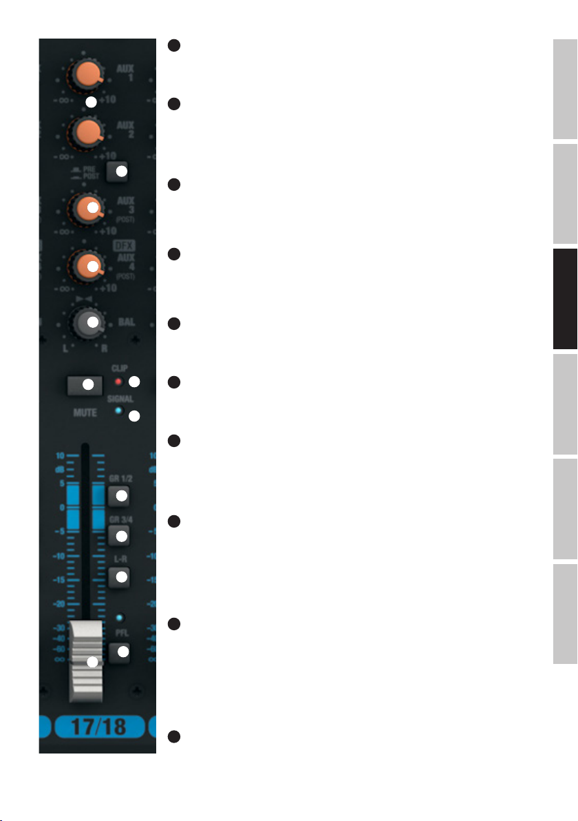
AUX 3 POST VOIES 17/18 & 19/20
49
Réglage de niveau du départ effet, signal prélevé sur les voies 17/18 et 19/20, envoyé sur le multieffet
externe (post fader). Le signal de départ auxiliaire global est disponible sur la sortie ligne AUX SEND 3 (n°12).
47
48
49
50
51
52
55
54
56
LEVEL DFX / AUX 4 POST VOIES 17/18 & 19/20
50
Réglage de niveau du départ effet, signal prélevé sur les voies 17/18 et 19/20, envoyé sur le multieffet numérique interne (post fader). Si vous utilisez un multieffet externe, reliez-le à la sortie ligne AUX SEND 4 (n°12).
Dès que vous insérez un jack dans la sortie jack AUX SEND 4, le multieffet interne est coupé automatiquement : il n’est donc pas utilisable.
BAL VOIES 17/18 & 19/20
51
Le potentiomètre Balance permet de modifier l’équilibre entre le canal gauche et le canal droit de la source
stéréo. Lorsque seul le connecteur du canal gauche (XLR ou jack) d’une entrée stéréo est utilisé (mode
MONO), le potentiomètre BAL devient un potentiomètre PAN.
MUTE VOIES 17/18 & 19/20
52
Pour couper le signal d’une voie (fonction Mute), appuyez sur sa touche MUTE (position enfoncée). L’indicateur LED MUTE de la voie s’allume alors. Appuyez de nouveau sur la touche MUTE pour désactiver la fonction
Mute : l’indicateur LED MUTE s’éteint.
FADERS VOIES 17/18 & 19/20
53
Réglage de volume pour les voies d’entrée 17/18 et 19/20. Montez le fader pour augmenter le niveau sur la
voie désirée, baissez le fader pour le réduire.
LED SIGNAL VOIES 17/18 & 19/20
54
La LED SIGNAL s’allume dès qu’un signal audio est présent sur la voie correspondante (selon le niveau de ce
signal d’entrée et le réglage du préampli ou de la sensibilité d’entrée - GAIN).
LED CLIP VOIES 17/18 & 19/20
55
Dès que la LED rouge Clip s’allume, c’est que l’entrée de la voie approche la limite de la distorsion. Réglez le
potentiomètre Gain (n°41) de façon à ce que la LED Clip ne clignote qu’occasionnellement. Évitez d’allumer la
LED Clip de façon continue. Pour ce faire, réduisez le gain sur le préampli micro (ou la sensibilité de l’entrée
ligne).
FRANCAISDEUTSCHENGLISH
GR 1/2 VOIES 17/18 & 19/20
56
57
58
59
53
La touche GR 1/2 permet d’assigner le signal de la voie aux groupes 1 et 2, en tenant compte de la position
du potentiomètre de panoramique : si PAN/BAL est tourné à fond à gauche, le signal de la voie ne part que sur
le Groupe 1 ; s’il est tourné à fond à droite, sur le Groupe 2 ; s’il est centré, le signal part à niveau égal sur les
Groupes 1 et 2. Le signal collecté sur les groupes 1/2 est disponible sur la sortie au niveau ligne GROUP OUT
1/2. Le niveau global du signal des groupes 1 et 2 se règle par l’intermédiaire du fader GROUP 1/2 (n°104) ; si
vous désirez affecter le signal audio des groupes aux généraux MAIN MIX, appuyez sur la touche L-R (n°105)
GR 3/4 VOIES 17/18 & 19/20
57
La touche GR 3/4 permet d’assigner le signal de la voie aux groupes 3 et 4, en tenant compte de la position
du potentiomètre de panoramique : si PAN est tourné à fond à gauche, le signal de la voie ne part que sur le
Groupe 3 ; s’il est tourné à fond à droite, sur le Groupe 4 ; s’il est centré, le signal part à niveau égal sur les
Groupes 3 et 4. Le signal collecté sur les groupes 3/4 est disponible sur la sortie au niveau ligne GROUP OUT
3/4 Le niveau du signal des bus des groupes 3 et 4 se règle par l’intermédiaire du fader GROUP 3/4 (n°106)
; si vous désirez affecter le signal audio des groupes aux généraux MAIN MIX, appuyez sur la touche L-R
(n°107).
58
L-R VOIES 17/18 & 19/20
Lorsque cette touche est enfoncée, le signal audio des voies 17/18 et 19-20) est envoyé sur les généraux
MAIN MIX de la console.
ITALIANOPOLSKIESPAÑOL
47
Page 48
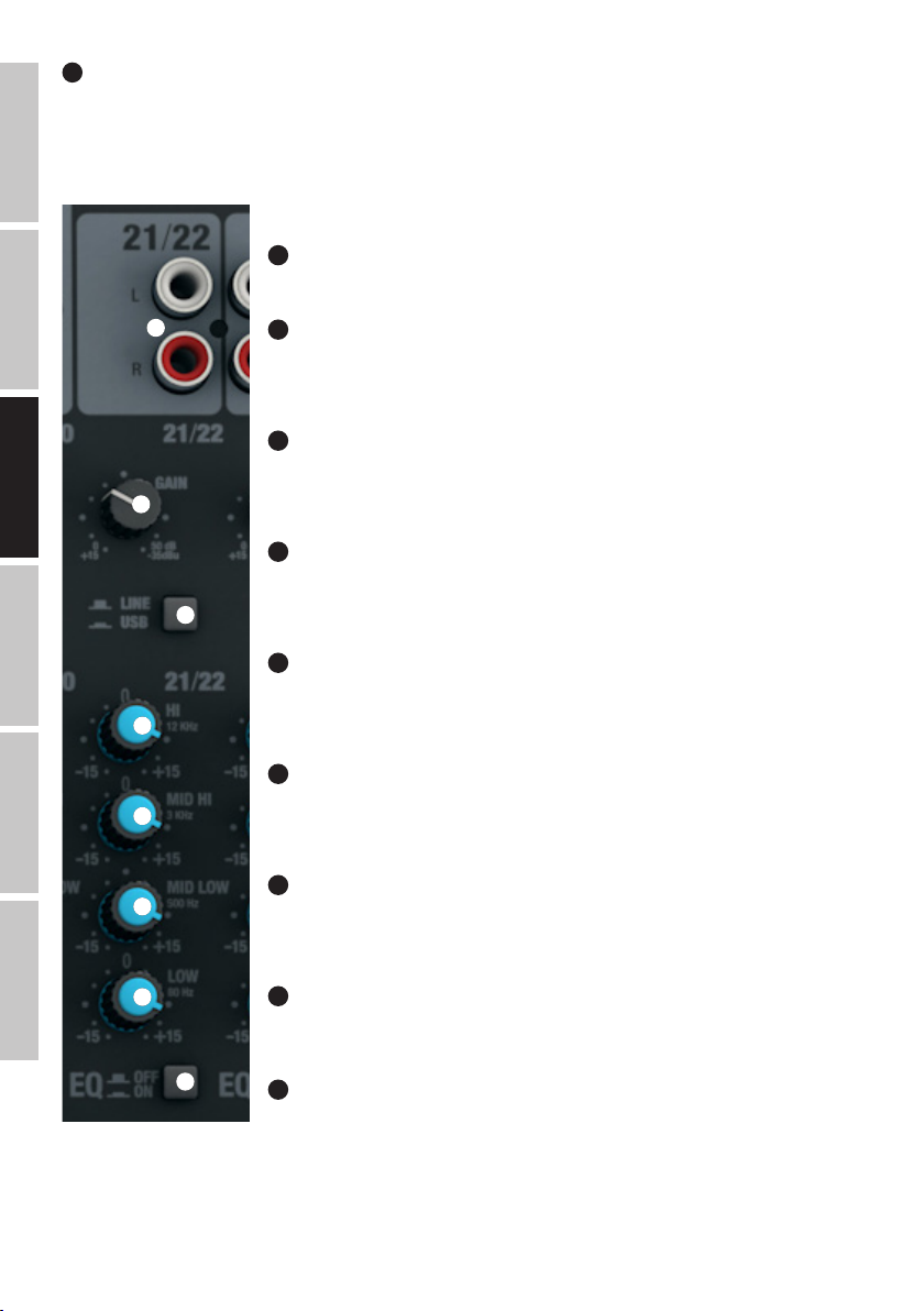
PFL VOIES 17/18 & 19/20
59
La touche PFL (Pre Fader Listening), activant l’écoute directe du signal de la voie avant passage par le fader, s’utilise dans deux cas : 1)
pour vérifier le signal de la voie correspondante indépendamment de la position du fader (n°53), en écoutant sur un casque branché sur la sortie
PHONES (n°82) ; 2) pour régler plus précisément le gain d’entrée de la voie, puisque le niveau du signal d’entrée est alors visualisé sur le vumètre
à 12 LED des généraux MAIN MIX. Lorsque vous enfoncez la touche PFL d’une voie, son indicateur LED PFL s’allume, ainsi que celui situé sous le
vumètre des généraux MAIN MIX. Dès que la touche PFL n’est plus enfoncée, les LED PFL s’éteignent.
ENGLISH
VOIES STÉRÉO 21/22 ET 23/24
LINE IN L/R VOIES 21/22 & 23/24
60
Entrées ligne asymétriques sur connecteurs cinch/RCA L et R.
DEUTSCHFRANCAIS
ESPAÑOL
60
61
62
63
64
65
61
GAIN VOIES 21/22 & 23/24
Réglage de sensibilité de l’entrée ligne, de +15 à -35 dBu. Réglez le potentiomètre de gain de façon à ce que
la LED Clip de la voie ne clignote qu’occasionnellement. Évitez d’allumer la LED Clip de façon continue. Pour
ce faire, réduisez la sensibilité de l’entrée ligne ou le volume de sortie de la source audio.
62
LINE/USB 21/22
Sélecteur de source de signal pour la voie stéréo 21/22. En position non enfoncée, ce sont les connecteurs
cinch/RCA qui sont la source du signal ; en position enfoncée, c’est le port USB, situé sur le panneau arrière
de la console.
63
ÉGALISEUR HI VOIES 21/22 & 23/24
Égaliseur d’aigus pour les voies 21/22 ou 23/24 (fréquence centrale 12 kHz, +/-15 dB). Tourner vers la
gauche pour baisser les aigus, vers la droite pour les monter. En position centrale (crantée), le correcteur est
inactif.
64
ÉGALISEUR MID HI VOIES 21/22 & 23/24
Égaliseur de hauts-médiums pour les voies 21/22 ou 23/24 (fréquence centrale 3 kHz, +/-15 dB). Tourner
vers la gauche pour baisser les hauts-médiums, vers la droite pour les monter. En position centrale (crantée),
le correcteur est inactif.
65
ÉGALISEUR MID LOW VOIES 21/22 & 23/24
Égaliseur de bas-médiums pour les voies 21/22 ou 23/24 (fréquence centrale 500 Hz, +/-15 dB). Tourner
vers la gauche pour baisser les bas médiums, vers la droite pour les monter. En position centrale (crantée), le
correcteur est inactif.
66
ÉGALISEUR LOW VOIES 21/22 & 23/24
Égaliseur de graves pour les voies 21/22 ou 23/24 (fréquence centrale 80 Hz, +/-15 dB). Tourner le
potentiomètre vers la gauche pour baisser les graves, vers la droite pour les monter. En position centrale
(crantée), le correcteur est inactif.
ITALIANO POLSKI
48
66
67
67
EQ ON/OFF VOIES 21/22 & 23/24
Touche d’activation/désactivation des 4 bandes d’égaliseur (HI, MID HI, MID LOW et LOW). Lorsque la touche
est enfoncée, l’égaliseur est activé ; il est désactivé lorsqu’il n’est pas enfoncé.
68
AUX 1 + AUX 2 VOIES 21/22 & 23/24
Réglage de niveau du signal prélevé sur les voies 21/22 et 23/24 pour envoi vers un multieffet externe (départ
effet, sélecteur n°69 en position POST) ou pour mixage de retours sur scène (départ Monitor, sélecteur n°69
en position PRE). Les signaux des bus de départ auxiliaires sont disponibles sur les sorties ligne AUX SEND 1
et 2 (n°12).
Page 49
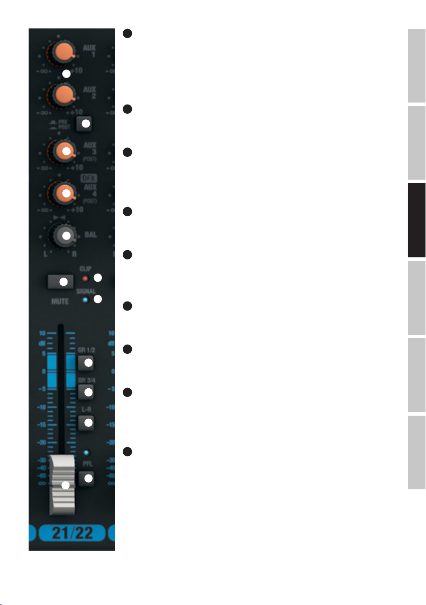
69
AUX 1 + AUX 2 PRE/POST VOIES 21/22 & 23/24
Si vous désirez utiliser les départs AUX 1 et 2 pour alimenter un multieffet externe, le sélecteur doit se trouver
en position POST (touche enfoncée). Dans ce cas, le signal de départ auxiliaire est prélevé après son passage
par le fader (n°74) de la voie : il est donc dépendant de la position du fader . Pour alimenter des retours de
68
69
scène, le sélecteur doit se trouver en position PRE (touche non enfoncée). Dans ce cas, le signal de départ
auxiliaire est prélevé avant son passage par le fader (n°74) de la voie : il est donc indépendant de la position
du fader.
70
AUX 3 POST VOIES 21/22 & 23/24
Réglage de niveau du départ effet, signal prélevé sur les voies 21/22 et 23/24, envoyé sur le multieffet interne
(post fader). Le signal du bus de départ auxiliaire est disponible sur la sortie ligne AUX SEND 3 (n°12).
70
71
72
73
77
78
79
71
LEVEL DFX / AUX 4 POST VOIES 21/22 & 23/24
Réglage de niveau du départ effet, signal prélevé sur les voies 21/22 à 23/24, envoyé sur le multieffet interne
(post fader). Si vous utilisez un multieffet externe, reliez-le à la sortie ligne AUX SEND 4 (n°12). Dès que vous
insérez un jack dans la sortie jack AUX SEND 4, le multieffet interne est coupé automatiquement : il n’est
donc pas utilisable.
72
BAL VOIES 21/22 & 23/24
Le potentiomètre Balance permet de modifier l’équilibre entre le canal gauche et le canal droit de la source
stéréo.
73
MUTE VOIES 21/22 & 23/24
Pour couper le signal d’une voie (fonction Mute), appuyez sur sa touche MUTE (position enfoncée). L’indicateur LED MUTE de la voie s’allume alors. Appuyez de nouveau sur la touche MUTE pour désactiver la fonction
76
Mute : l’indicateur LED MUTE s’éteint.
75
74
FADERS VOIES 21/22 & 23/24
Réglage de volume pour les voies d’entrée 21/22 et 23/24. Montez le fader pour augmenter le niveau sur la
voie désirée, baissez le fader pour le réduire.
75
LED SIGNAL VOIES 21/22 & 23/24
La LED SIGNAL s’allume dès qu’un signal audio est présent sur la voie correspondante (selon le niveau de ce
signal d’entrée et le réglage du préampli ou de la sensibilité d’entrée - GAIN).
76
LED CLIP VOIES 21/22 & 23/24
Dès que la LED rouge Clip s’allume, c’est que l’entrée de la voie approche la limite de la distorsion. Réglez le
potentiomètre Gain (n°61) de façon à ce que la LED Clip ne clignote qu’occasionnellement.. Évitez d’allumer
la LED Clip de façon continue. Pour ce faire, réduisez la sensibilité de l’entrée ligne ou baissez le volume de
sortie de la source de signal.
FRANCAISDEUTSCHENGLISH
ITALIANOPOLSKIESPAÑOL
77
GR 1/2 VOIES 21/22 & 23/24
La touche GR 1/2 permet d’assigner le signal de la voie aux groupes 1 et 2, selon la position du potentiomètre
80
74
de panoramique : si le potentiomètre BAL est tourné à fond à gauche, le signal de la voie ne part que sur le
Groupe 1 ; s’il est tourné à fond à droite, sur le Groupe 2 ; s’il est centré, le signal part à niveau égal sur les
Groupes 1 et 2. Le signal collecté sur les groupes 1/2 est disponible sur la sortie au niveau ligne GROUP OUT
1/2. Le niveau global du signal des groupes 1 et 2 se règle par l’intermédiaire du fader GROUP 1/2 (n°104) ; si
vous désirez affecter le signal audio des groupes aux généraux MAIN MIX, appuyez sur la touche L-R (n°105)
49
Page 50

ENGLISH
DEUTSCHFRANCAIS
87
90
ESPAÑOL
GR 3/4 VOIES 21/22 & 23/24
78
La touche GR 3/4 permet d’assigner le signal de la voie aux groupes 3 et 4, en tenant
compte de la position du potentiomètre de panoramique : si le potentiomètre BAL est
81
83
84
88
91
92
82
85
86
89
98
99
95
100
101
tourné à fond à gauche, le signal de la voie ne part que sur le Groupe 3 ; s’il est tourné
à fond à droite, sur le Groupe 4 ; s’il est centré, le signal part à niveau égal sur les
Groupes 1 et 2. Le signal collecté sur les groupes 3/4 est disponible sur la sortie au
niveau ligne GROUP OUT 3/4 Le niveau global du signal des bus des groupes 3 et 4 se
règle par l’intermédiaire du fader GROUP 3/4 (n°106) ; si vous désirez affecter le signal
audio des groupes aux généraux MAIN MIX, appuyez sur la touche L-R (n°107).
79
TOUCHE L-R VOIES 21/22 & 23/24
Lorsque cette touche est enfoncée, le signal audio de la voie (21/22 et 23/24) est
envoyé sur les généraux MAIN MIX de la console.
80
PFL VOIES 21/22 & 23/24
La touche PFL (Pre Fader Listening), activant l’écoute directe du signal de la voie
avant passage par le fader, s’utilise dans deux cas : 1) pour vérifier le signal de la
voie correspondante indépendamment de la position du fader (n°74), en écoutant sur
un casque branché sur la sortie PHONES (n°82) ; 2) pour régler plus précisément le
gain d’entrée de la voie, puisque le niveau du signal d’entrée est alors visualisé sur
le vumètre à 12 LED des généraux MAIN MIX. Lorsque vous enfoncez la touche PFL
d’une voie, son indicateur LED PFL s’allume, ainsi que celui situé sous le vumètre
des généraux MAIN MIX. Dès que la touche PFL n’est plus enfoncée, les LED PFL
s’éteignent.
SECTION MASTER
81
CONNECTEUR POUR LAMPE
Port USB de Type A pour branchement d’une lampe de console. Attention à ce que
les caractéristiques du port et de la lampe connectée concordent (tension continue 5
volts, intensité maximale 500 mA).
ITALIANO POLSKI
50
93 95
94 97
108
105
104 106 110
109
111
107
103
102
82
SORTIE CASQUE
Sortie jack 6,35 mm stéréo pour branchement d’un casque. Ce connecteur permet de
choisir le signal écouté :
A. Touche n°100 (CTRL ROOM SOURCE MAIN/GR) non enfoncée et aucune touche PFL
enfoncée : Signal des généraux MAIN MIX.
B. Touche n°100 enfoncée et aucune touche PFL enfoncée : Signaux des groupes
GROUP GR 1/2, ou GR 3/4 (selon la position de la touche n°101 GR 1/2 / GR 3/4).
C. Une ou plusieurs touches PFL enfoncées sur les entrées : Écoute directe des
signaux d’entrée de la voie ou des voies correspondantes (écoute avant fader, Pre
Fader Listening).
83
STEREO GRAPHIC EQ
Égaliseur graphique 7 bandes sur généraux MAIN MIX
84
EQ ON/OFF
Touche d’activation/désactivation de l’égaliseur graphique des généraux (n°83).
L’égaliseur est activé quand la touche est enfoncée ; il est désactive sinon.
85
INDICATEUR LED +48V
Dès que l’alimentation fantôme de la console est activée (touche n°3 sur le panneau
arrière), l’indicateur LED +48V s’allume.
Page 51

86
LED POWER
La LED POWER s’allume dès que la console est correctement reliée au secteur et allumée.
87
AFFICHEUR PRESETS DFX
Afficheur LED à 2 caractères indiquant le numéro du preset d’effets (00 - 99).
88
PRESETS DFX
Encodeur/sélecteur pour choix et activation du preset d’effets. Sélectionnez le preset désiré en tournant l’encodeur, et activez-le en appuyant sur
l’encodeur.
89
LISTE PRESETS DFX
Liste des effets numériques disponibles.
90
LED PEAK DFX
Dès que la LED rouge s’allume, c’est que l’entrée du multieffet interne est à la limite de la distorsion. Dans ce cas, baissez le niveau du bus de
départ effet DFX SEND AUX 4 (n°94) de façon à ce que la LED Peak ne s’allume qu’occasionnellement sur les crêtes de signal.
91
DFX MUTE
Pour couper la sortie du multieffet interne, appuyez brièvement sur la touche DFX Mute ; pour désactiver la fonction Mute, appuyez de nouveau sur
la touche. Lorsque la fonction Mute est activée sur le multieffet, la LED Peak (n°90) reste allumée en permanence.
92
SEND AUX 1 & AUX 2
Ce potentiomètre permet de régler le niveau global du bus DFX/AUX2, recueillant les signaux prélevés sur chacune des voies 1 à 23/2 via le
potentiomètre DFX/AUX2
93
AUX SEND 3
Potentiomètre de réglage de niveau du bus AUX 3, prélevé via les départs des voies d’entrée 1 à 23/24.
FRANCAISDEUTSCHENGLISH
94
SEND AUX 4 / DFX
Potentiomètre de réglage de niveau du bus AUX1, prélevé via les départs (n°10) des voies d’entrée 1 à 23/24.
95
DFX TO AUX 1 & AUX 2
Réglage de niveau du retour du multieffet intégré sur les bus AUX 1 et AUX 2.
96
DFX OUT
Réglage de niveau de la sortie stéréo GR OUT (n°48)
97
DFX TO MAIN
Ce fader permet de doser le signal de retour effet du multieffet interne sur les généraux MAIN MIX.
98
OUTPUT LEVEL
Indicateur de niveau sur 2x12 segments LED, pour visualisation du niveau du signal stéréo des généraux (MAIN MIX) ou du signal d’entrée d’une
voie d’entrée sur laquelle la touche PFL est enfoncée – autorisant ainsi un réglage plus précis du gain d’entrée. Afin d’éviter toute distorsion,
réduisez le niveau de sortie sur les généraux MAIN MIX (n°110), ou réduisez les niveaux des signaux d’entrée via les potentiomètres GAIN correspondants dès que la LED rouge CLIP s’allume.
99
LED PFL
La LED PFL s’allume dès qu’une ou plusieurs touches PFL sont enfoncées sur les voies d’entrée.
ITALIANOPOLSKIESPAÑOL
51
Page 52

100
CTRL ROOM SOURCE MAIN / GR
Sélecteur de source permettant de choisir le signal envoyé sur la sortie CTRL ROOM (n°10) et sur la sortie casque (n°82). Lorsque la touche n’est
pas enfoncée, le signal des généraux (MAIN MIX) est envoyé ; lorsque la touche est enfoncée, c’est le signal des groupes GR1/2 ou GR3/4 (selon la
position du sélecteur n°101, GR 1/2 / GR 3/4)
ENGLISH
101
CTRL ROOM SOURCE GR1/2 / GR3/4
Si la touche CTRL ROOM SOURCE MAIN / GR (n°100) est enfoncée, cette touche permet de choisir les groupes 1/2 ou 3/4 comme source de signal
pour la Control Room (touche non enfoncée : GR1/2, touche enfoncée = GR3/4).
102
CTRL ROOM LEVEL
Réglage de niveau pour la sortie ligne CTRL ROOM (n°10). Avant mise sous tension du système d’écoute ou de la sonorisation connectée, réglez le
volume au minimum.
DEUTSCHFRANCAIS
103
NIVEAU CASQUE
Réglage de volume pour la sortie casque (n°82). Utilisez un casque d’une impédance d’au moins 30 ohms, et veillez à ne pas dépasser un niveau
d’écoute confortable, afin d’éviter tout dommage auditif. Avant de brancher votre casque, réglez le volume au minimum.
104
GROUP 1/2
Réglage de volume du signal sur les sorties ligne GROUP OUT 1 et 2 (n°11) et de la réinjection du signal des groupes 1/2 sur les généraux (MAIN
MIX) lorsque la touche GROUP 1/2 L-R est enfoncée. Avant mise sous tension de la sonorisation connectée, réglez le volume au minimum (fader
baissé).
105
GROUP 1/2 L-R
Touche d’assignation du signal des groupes GROUP 1/2 aux généraux MAIN MIX.
106
GROUP 3/4
Réglage de volume du signal sur les sorties ligne GROUP OUT 3 et 4 (n°11) et de la réinjection du signal des groupes 3/4 sur les généraux (MAIN
ESPAÑOL
MIX) lorsque la touche GROUP 3/4 L-R est enfoncée. Avant mise sous tension de la sonorisation connectée, réglez le volume au minimum (fader
baissé).
107
GROUP 3/4 L-R
Touche d’assignation du signal des groupes GROUP 3/4 aux généraux MAIN MIX.
108
GROUP 1/2 MUTE
Enfoncez la touche pour couper le signal des groupes GROUP 1/2. L’indicateur LED MUTE de la voie s’allume alors. Appuyez de nouveau sur la
touche MUTE pour désactiver la fonction Mute : l’indicateur LED MUTE s’éteint.
109
GROUP 3/4 MUTE
Enfoncez la touche pour couper le signal des groupes GROUP 3/4. L’indicateur LED MUTE de la voie s’allume alors. Appuyez de nouveau sur la
touche MUTE pour désactiver la fonction Mute : l’indicateur LED MUTE s’éteint.
ITALIANO POLSKI
110
MAIN MIX
Réglage de niveau du signal des sorties stéréo MAIN MIX OUTPUT (n°5 et n°6). Levez le fader pour augmenter le volume sonore, baissez-le pour le
réduire. Avant mise sous tension de la sonorisation connectée, réglez le volume au minimum (fader baissé).
111
MAIN MIX MUTE
Enfoncez la touche pour couper le signal des généraux MAIN MIX. L’indicateur LED MUTE de la voie s’allume alors. Appuyez de nouveau sur la
touche MUTE pour désactiver la fonction Mute : l’indicateur LED MUTE s’éteint.
52
Page 53

INSTALLATION PORT USB
Installation sous Windows (Windows XP® ou ultérieur) :
Il n'est pas nécessaire d'installer des pilotes spécifiques, par téléchargement ou depuis un support de masse externe, pour pouvoir utiliser la
console. Reliez la console, via le câble USB livré, à l'un des ports USB 2.0 de votre ordinateur. Dans la plupart des cas, l'installation du pilote logiciel
nécessaire se lance alors automatiquement. Après cette installation, il faut redémarrer l'ordinateur. Dans certains cas, une fenêtre apparaît, vous
invitant à procéder à l'installation du logiciel USB Audio CODEC. Suivez alors les instructions. Dans le Gestionnaire de Périphériques de Windows,
la console apparaît ensuite sous "Contrôleurs audio, vidéo et jeu" en tant qu'élément "USB Audio CODEC" ou "Périphérique Audio USB" ; elle est
alors prête à l'emploi. Selon le logiciel d'enregistrement que vous utilisez, il peut être nécessaire de sélectionner la console en tant que périphérique
d'enregistrement et de lecture dans la fenêtre "Son" ("Démarrer"→"Panneaux de Configuration"→"Son").
Installation sous Mac OS X (Mac OS X® 10.5 ou ultérieur) :
Il n'est pas nécessaire d'installer des pilotes spécifiques, par téléchargement ou depuis un support de masse externe, pour pouvoir utiliser la
console. Reliez la console, via le câble USB livré, à l'un des ports USB 2.0 de votre ordinateur. L'installation du pilote logiciel nécessaire se lance
alors automatiquement. Selon le logiciel d'enregistrement que vous utilisez, il peut être nécessaire de sélectionner la console (USB Audio CODEC) en
tant que périphérique d'enregistrement et de lecture dans le tableau de bord "Son" ("Préférences Système"→"Son").
CARACTÉRISTIQUES TECHNIQUES
Référence Modèle : LDVIBZ24DC
Type de Produit : Table de mixage analogique
Utilisation : compatible sonorisation ou enregistrement
Nombre de Canaux : 24
Canaux mono :
Voies Micro/Ligne Mono : 16
Connecteurs Entrée Micro/Ligne Mono : jack 6,35 mm TRS, XLR
Type d'entrée mono : symétrie électronique, composants discrets
Réponse en Fréquence Entrée Micro Mono : 10 Hz - 45 kHz
Gain d'Entrée sur Entrée Micro Mono : 50 dB
Séparation des Canaux : 90 dB
THD sur Entrée Micro Mono : 0,0058%
Impédance d'Entrée Micro Mono : 4 kohms
Rapport Signal/Bruit Entrée Micro Mono : 113 dB
Type d'entrée Ligne mono : Symétrie électronique, composants discrets
Gain d'Entrée sur Entrée Ligne Mono : 50 dB
THD sur Entrée Ligne Mono : 0,0045%
Impédance Entrée Ligne Mono : 21 kohms
Rapport Signal/Bruit Entrée Ligne Mono : 116 dB
Égaliseur Aigus Voie Mono : +/- 15 dB à 12 kHz
Égaliseur Médiums Voie Mono : +/- 15 dB, fréquence réglable entre 200 Hz et 8 kHz
Égaliseur Graves Voie Mono : +/- 15 dB à 80 Hz
Points d'Insertion : Sur voies 1 - 8
Connecteurs Points d'Insertion : jack 6,35 mm TRS (pointe = départ, anneau = retour)
Alimentation Fantôme : Tension continue 48 volts commutable sur entrées XLR
Filtre passe-haut (Low Cut) : 95 Hz
Hi-Z (haute impédance) : Commutateur sur voies d’entrée 1 à 4 (> 50 kohms)
Compresseur : Sur voies 1 - 8 :
Contrôles sur voies mono 1 - 16 : Gain, Low Cut, High-Z (voies 1 - 4), Compressor (voies 1 - 8), EQ Hi, EQ Mid, EQ
Mid Freq, EQ Low, EQ on/off, DFX, AUX Send 1-2 pre (AUX2 commutable pre/post),
AUX Send 3-4 post, Channel Mute, sélecteur d’assignation des faders (Groupes 1/2,
Groupes 3/4, généraux Main L+R), Pan/Bal, fader de voie, touche PFL
FRANCAISDEUTSCHENGLISH
ITALIANOPOLSKIESPAÑOL
53
Page 54

Voies Stéréo :
Nombre de Voies d'Entrée Ligne Stéréo : 4
Connecteurs Entrée Ligne Stéréo : 2 x jack TRS 6,35 mm (L compatible mono, R), 2 x RCA/cinch
Type Entrée Ligne Stéréo : asymétrique
Port d’entrée/sortie USB : USB-type B (assigné aux voies 21/22)
ENGLISH
Réponse en Fréquence Entrée Ligne Stéréo : 10 Hz - 45 kHz
Gain d'Entrée sur Entrée Ligne Stéréo : 50 dB
Séparation des Canaux : 62 dB
THD sur Entrée Ligne Stéréo : 0,0045%
Impédance d'Entrée Ligne Stéréo : 3,7 kohms
Rapport S/B Entrée Ligne Stéréo : 116 dB
Égaliseur Aigus Voie Stéréo : +/- 15 dB à 12 kHz
DEUTSCHFRANCAIS
Égaliseur Haut-Médium Voie Stéréo : +/- 15 dB à 3 kHz
Égaliseur Bas-Médium Voie Stéréo : +/- 15 dB à 500 Hz
Égaliseur Graves Voie Stéréo : +/- 15 dB à 80 Hz
Contrôles sur voies 17/18 - 23/24 : Gain, sélecteur LINE/USB (voies 21/22), EQ Hi, EQ Mid, EQ Mid Freq, EQ Low, EQ on/
Section Master :
Nombre de Départs AUX/Effet : 4
Connecteurs Départ AUX/Effet : 4 x jacks 6,35 mm 3 points, câblés en asymétrique
Sortie Stéréo Généraux Symétrique : 2
Connecteur Sortie Généraux Symétrique : 2 x jack 6,35 mm TRS, 2 x XLR mâles
Impédance Sortie Généraux Symétrique : 120 ohms
ESPAÑOL
Niveau Maximal Sortie Généraux Symétrique
(Asymétrique) :
Nombre de Sorties Stéréo Control Room : 1
Connecteurs Sortie Stéréo Control Room : 2 x jack 6,35 mm
Nombre de Sorties Groupe (GR OUT) : 4
Connecteurs de Sorties Groupe : 4 x jack 6,35 mm
Sortie Casque : 1
Connecteur Sortie Casque : jack stéréo 6,35 mm
Impédance minimale casque : 30 ohms
Processeur d'Effet Numérique Intégré : oui
Nombre de Presets : 100
Entrée Sélecteur au Pied DFX Mute : jack 6,35 mm (pédale Footswitch en option)
Contrôleurs sur Section Master : Égaliseur graphique 7 bandes, EQ On/Off, DFX Presets, DFX Mute, AUX/DFX Send 1 - 4,
ITALIANO POLSKI
off, DFX, AUX Send 1-2 pre (AUX2 commutable pre/post), AUX Send 3-4 post, Channel
Mute, sélecteur d’assignation du Fader (Groupes 1/2, Groupes 3/4, généraux Main
L+R), Bal, fader de voie, touche PFL
+22 dBu (+20 dBV)
DFX to Main, DFX to Aux, Phones, CTRL, sélecteur GROUP to Main, touche alimentation
fantôme +48V, Fader de généraux (Main Mix), Faders Group, Power, CTRL Room
Source MAIN/GR, GR1/2 - GR3/4, Group Mute, Main Mute
54
Page 55
Caractéristiques Générales :
Indicateurs : CLIP (écrêtage sur la voie), Signal (présence d'un signal sur la voie), CLIP Effet,
Afficheur LED DFX, Power, alimentation fantôme, échelle 2 x 12 LED pour visualisation
niveau généraux, LED Mute
Connecteur pour lampe console : Port USB-A, tension continue 5 volts, intensité maxi 500 mA
Entrée/Sortie audio via USB : Protocole USB 2.0, convertisseurs 16 bits Delta-Sigma
N/A : 32 kHz, 44,1 kHz, 48 kHz
A/N : 8 kHz, 11,025 kHz, 16 kHz, 22,05 kHz, 32 kHz, 44,1 kHz, 48 kHz
Branchement Secteur : Embase Format IEC
Tension Secteur : 100 à 240 volts 50/60 Hz
Consommation Électrique (maxi) : 70 W
Fusible : T1,6AL / 250 V
Température d'Utilisation : 0°C à +45°C
Taux d'hygrométrie ambiante : 10 à 80% (relative)
Largeur : 712 mm
Hauteur : 80 mm
Profondeur : 425 mm
Masse : 9,36 kg
DECLARATIONS
GARANTIE FABRICANT & LIMITATION DE RESPONSABILITÉ
Nos conditions actuelles de garantie et de limitation de responsabilité sont disponibles à l‘adresse suivante :http://www.adamhall.com/media/shop/downloads/documents/manufacturersdeclarations.pdf. Pour les réparations, veuillez contacter Adam Hall GmbH, Daimlerstraße 9,
61267 Neu Anspach / E-Mail Info@adamhall.com / +49 (0)6081 / 9419-0. Vous pouvez nous demander la déclaration de conformité actuelle à l’adresse info@adamhall.com.
TRI ET MISE AUX DÉCHETS CORRECTE DE CE PRODUIT
(Applicable dans l‘Union Européenne et les autres pays européens pratiquant le tri des déchets) La présence de ce symbole sur le
produit ou sur la documentation correspondante indique qu‘en fin de vie, le produit ne doit pas être jeté avec les déchets normaux,
afin d‘éviter tout dommage à l‘environnement ou aux personnes consécutive à une élimination non contrôlée des déchets. Séparez-le des
autres types de déchets et recyclez-le, afin de promouvoir la réutilisation durable des ressources naturelles. Nous conseillons aux
utilisateurs non professionnels de contacter le revendeur chez qui ils ont acheté le produit, ou un représentant gouvernemental local, pour
plus de détails sur le lieu de collecte et la façon de recycler cet appareil dans le meilleur respect de l‘environnement possible.. Nous invitons
les utilisateurs professionnels à contacter leur fournisseur et à vérifier les termes et conditions de leur contrat d‘achat. Ce produit ne doit
pas être mélangé à d‘autres déchets commerciaux lors de la collecte.
FRANCAISDEUTSCHENGLISH
55
ITALIANOPOLSKIESPAÑOL
Page 56

ESPAÑOL
¡GRACIAS POR ELEGIR LD-SYSTEMS!
Este equipo está diseñado y fabricado con los estándares de calidad más exigentes, para garantizar un correcto funcionamiento durante
muchos años. Los productos de LD-Systems se caracterizan por su gran calidad, avalada por el prestigio de la marca y una dilatada experiencia como fabricante. Lea atentamente este manual de usuario para poder aprovechar rápidamente toda la funcionalidad de su nuevo
ENGLISH
producto de LD Systems.
Si desea obtener información sobre LD-SYSTEMS, visite nuestro sitio web WWW.LD-SYSTEMS.COM
MEDIDAS DE SEGURIDAD
1. Lea atentamente las instrucciones de este manual.
2. Guarde toda la información en un lugar seguro para futuras consultas.
3. Siga las instrucciones indicadas.
4. Siga todas las advertencias. No quite las instrucciones de seguridad ni cualquier otra información indicada en el equipo.
5. Utilice el equipo únicamente según la finalidad prevista.
6. Utilice solo soportes y fijaciones que sean robustos y adecuados cuando instale el equipo en instalaciones fijas. Asegúrese de que los
DEUTSCHFRANCAIS
soportes de pared están correctamente instalados y firmemente fijados. Asegúrese de que el equipo está sólidamente instalado y no se
puede caer.
7. Al instalar el equipo, respete las normas de seguridad aplicables en su país.
8. Evite instalar el equipo cerca de radiadores, acumuladores de calor, estufas o cualquier otra fuente de calor. Asegúrese de que el equipo esté
instalado en un lugar con ventilación suficiente para evitar cualquier sobrecalentamiento.
9. No coloque sobre el equipo fuentes de llamas sin protección, por ejemplo, velas encendidas.
10. Evite bloquear las rejillas de ventilación.
11. El equipo está diseñado para uso en interiores; no lo utilice cerca del agua (excepto los equipos específicamente diseñados para uso
en exterior, en cuyo caso tenga en cuenta las indicaciones mencionadas a continuación). No exponga este equipo a materiales, líquidos o
gases inflamables.
12. Evite exponer el equipo a gotas o salpicaduras que puedan caer dentro del mismo. No coloque recipientes llenos de líquido, como
floreros o vasos, sobre el equipo.
13. Asegúrese de no dejar caer ningún objeto dentro del equipo.
14. Emplee el equipo únicamente con los accesorios recomendados por el fabricante.
15. No abra el equipo ni intente modificarlo.
16. Una vez conectado el equipo, compruebe que en toda la longitud del cableado no hay peligro de que provoque una caída, por ejemplo.
17. Durante el transporte, asegúrese de que el equipo no se caiga y pueda causar daños personales o materiales.
18. Si el equipo no funciona correctamente, o si se ha vertido líquido sobre él, o si un objeto ha caído en su interior o si ha sufrido algún
desperfecto, apague inmediatamente el equipo y desenchufe el cable eléctrico (si se trata de un equipo activo). Únicamente un técnico
ESPAÑOL
especialista debe reparar el equipo.
19. Para limpiar el equipo utilice un paño seco.
20. Procure seguir las normas vigentes en su país sobre reciclaje de desechos. Separe los componentes de plástico, papel y cartón del
paquete para reciclarlos en sus contenedores respectivos.
21. No deje las bolsas de plástico al alcance de los niños.
PARA LOS EQUIPOS CON TOMA ELÉCTRICA:
22. ADVERTENCIA: Si el cable eléctrico está provisto de un contacto de protección, debe conectarse a una toma eléctrica con conexión a
tierra. No desactivar nunca esta conexión de protección a tierra del cable eléctrico.
23. Si el equipo ha estado expuesto a un cambio brusco de temperatura (por ejemplo, después del transporte), no lo encienda
inmediatamente. La condensación o la humedad podrían dañar el equipo. Deje que el equipo alcance la temperatura ambiente antes de
encenderlo.
24. Antes de conectar el cable eléctrico a la toma de corriente, compruebe si la tensión y la frecuencia del suministro eléctrico coinciden
con las especificaciones de este equipo. Si el equipo dispone de un selector de tensión, antes de enchufarlo a la red eléctrica, asegúrese de
que el valor seleccionado coincide con la tensión de suministro. Si el enchufe o el adaptador de corriente no encajan en la toma eléctrica,
consulte a un electricista.
25. Asegúrese de que el cable eléctrico no está pinzado. Evite que el cable resulte pellizcado, sobre todo en los extremos de conexión al
equipo y en la toma eléctrica.
26. Al conectar el equipo, asegúrese de que el cable eléctrico o el adaptador de corriente estén siempre accesibles. Desconecte el equipo
ITALIANO POLSKI
de la toma de corriente cuando no esté en uso o antes de limpiarlo. Para ello, desconecte el cable eléctrico y el adaptador de corriente del
conector del equipo en vez de desenchufar el cable de la toma eléctrica. No tocar el cable eléctrico ni el adaptador de corriente con las
manos húmedas.
27. No encienda y apague el equipo en cortos intervalos de tiempo, ya que se reduce así la vida útil del sistema.
28. NOTA IMPORTANTE: Sustituya los fusibles únicamente por otros del mismo tipo y de las mismas características. Si el fusible se funde
continuamente, póngase en contacto con un servicio técnico autorizado.
29. Para desconectar completamente el equipo de la tensión eléctrica, desenchufe el cable eléctrico o el adaptador de corriente de la toma
eléctrica.
30. Si el equipo dispone de un enchufe eléctrico Volex, deberá desbloquearse el Volex del equipo para desenchufarlo. Esto implica que un
tirón en el cable eléctrico puede desplazar el equipo y provocar daños personales o materiales. Por tanto, asegúrese de instalar los cables
con sumo cuidado.
31. Si es probable que caiga un rayo por una tormenta eléctrica o si no va a emplear el equipo durante mucho tiempo, desenchufe el cable
56
Page 57
eléctrico y el adaptador de corriente.
32. Al montar el equipo, asegúrese de que no está alimentado eléctricamente (el enchufe no debe estar conectado a la red eléctrica).
33. La acumulación de polvo y otras partículas en el interior del equipo puede causar daños. Dependiendo de las condiciones ambientales
(polvo, nicotina, niebla, etc.), deberá realizarse periódicamente el mantenimiento o la limpieza del equipo por personal especializado, para
evitar cualquier sobrecalentamiento o fallo de funcionamiento (mantenimiento y limpieza no cubiertos por la garantía).
34. Asimismo, deberá dejarse una distancia mínima de 0,5 metros con cualquier material inflamable.
35. Los cables eléctricos que sirven para alimentar a varios equipos deben tener una sección mínima de 1,5mm². En la Unión Europa debe
emplearse un cable de tipo H05VV-F, o similar. Adam Hall dispone de cables adecuados. Con estos cables podrá alimentar eléctricamente
varios equipos conectando el enchufe de salida POWER OUT de un equipo al de entrada POWER IN de otro equipo. Asegúrese de que el
consumo total de todos los equipos conectados no supere los amperios especificados del equipo (serigrafiado en el equipo). Además,
procure que las tiradas de cable sean lo más cortas posible.
ATENCIÓN:
Para evitar el riesgo de descarga eléctrica, no retire la tapa. El equipo no contiene elementos que
el usuario pueda reparar o sustituir. Para cualquier tarea de mantenimiento o reparación, acuda a
un técnico cualificado.
El símbolo de rayo dentro de un triángulo equilátero advierte al usuario de la presencia de tensiones peligrosas sin aislamiento
dentro del equipo que pueden causar una descarga eléctrica.
El símbolo de exclamación dentro de un triángulo equilátero advierte al usuario de la existencia de importantes instrucciones
de uso y mantenimiento.
¡Advertencia! Este símbolo indica la presencia de superficies calientes. Durante el funcionamiento, algunas partes de la
carcasa pueden llegar a calentarse bastante. Por ello, una vez apagado el equipo, espere al menos 10 minutos antes de
manipularlo o transportarlo.
¡ADVERTENCIA: ALTO VOLUMEN!
Este equipo se destina a un uso profesional. Por consiguiente, si se aplica a un uso comercial, estará sujeto a las normas y reglamentos
de la Asociación para la prevención de accidentes de su sector profesional. Como fabricante, Adam Hall tiene la obligación de informar
formalmente a los usuarios de la existencia de posibles riesgos para la salud. Daños auditivos por exposición prolongada a un nivel SPL
alto: este equipo puede generar fácilmente un nivel de presión sonora (SPL) lo suficientemente elevado como para causar daños auditivos
permanentes a los artistas, el personal de producción y el público. Deben tomarse precauciones para evitar la exposición prolongada a un
SPL de más de 90dB.
¡ATENCIÓN: INFORMACIÓN IMPORTANTE SOBRE LOS PRODUCTOS DE ILUMINACIÓN!
1. Este producto ha sido desarrollado para uso profesional en el sector de eventos y no está diseñado para la iluminación doméstica.
2. No mire directamente el haz de luz, ni siquiera momentáneamente.
3. No mire directamente el haz de luz con instrumentos ópticos, como lentes de aumento.
4. ¡Los efectos estroboscópicos pueden a veces causar convulsiones en personas fotosensibles! Las personas con epilepsia deben evitar los
lugares en los que se usan luces estroboscópicas.
INTRODUCCIÓN
LDVIBZ24DC - Mesa de mezclas de 24 canales con sección de efectos digitales y compresor
La VIBZ24DC es una mesa de mezclas versátil de 16entradas de micrófono balanceadas, con previos de alta calidad, filtro paso altos,
ecualizador de 3bandas con semiparamétrico de medios y alimentación fantasma conmutable, y otras 2entradas más se pueden utilizar
como canales de línea estéreo.
8canales de micrófono se pueden ajustar de forma independiente con el compresor integrado para conseguir un control eficaz de dinámica.
Los canales estéreo están equipados con ecualizador de 4bandas.
La sección master de la mesa de mezclas dispone de 2bucles de efectos, salidas XLR balanceadas, salidas de grupos y de monitorado, así
como conexión para auriculares. La mesa VIBZ 24 DC también dispone de un puerto USB para grabación directa de sonido en un ordenador,
una sección digital de efectos con 100presets y un conector para una lámpara de 5V.
Con importantes funciones como el PFL o los botones de silencio y su sonido natural y transparente, la mesa VIBZ24DC es la elección
perfecta para directos, instalaciones fijas y grabaciones caseras exigentes.
FRANCAISDEUTSCHENGLISH
ITALIANOPOLSKIESPAÑOL
57
Page 58
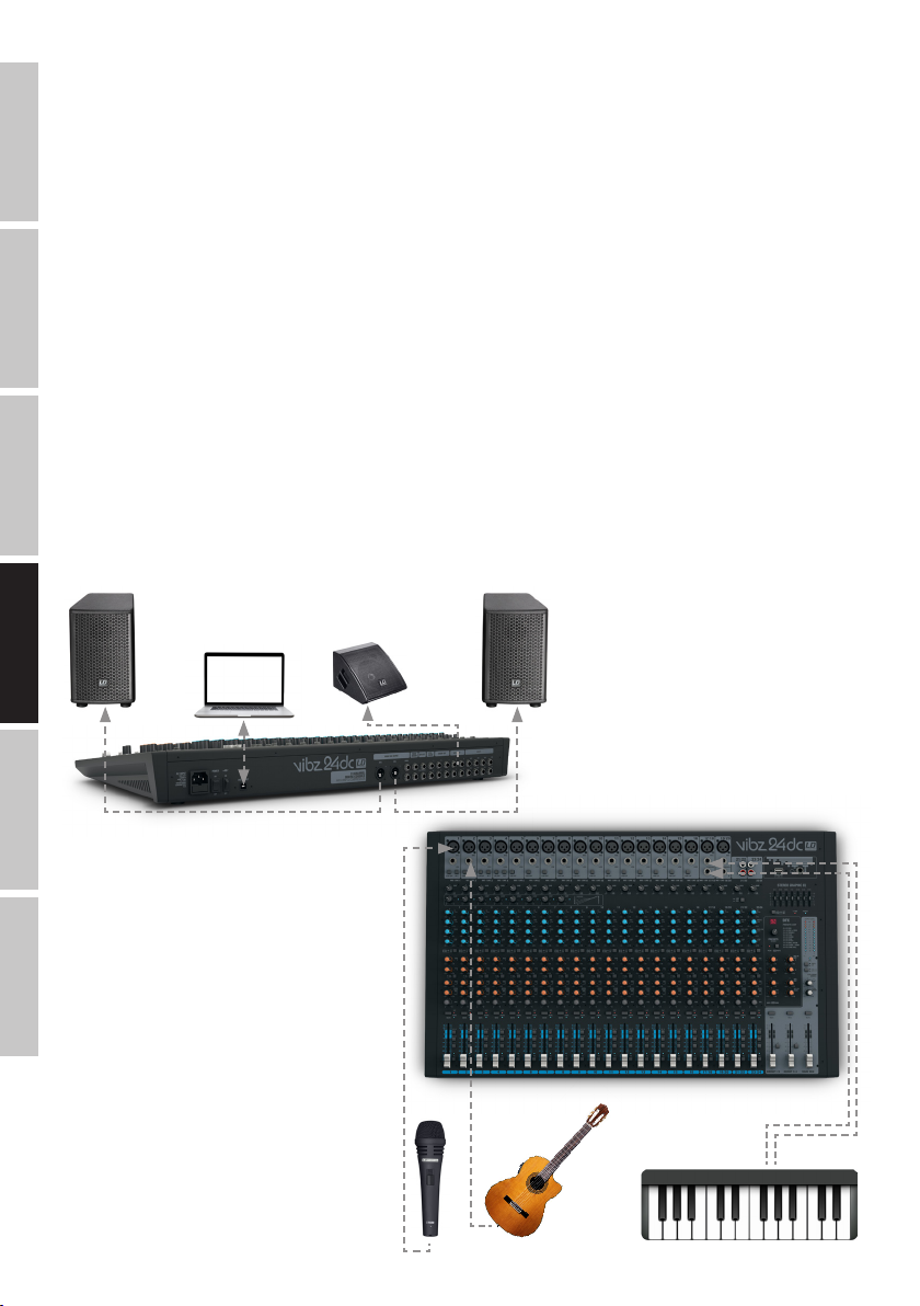
GUÍA RÁPIDA DE CABLEADO
1. Asegúrese de que están apagados la mesa de mezclas y todos los equipos conectados a la mesa de mezclas.
2. Conecte el equipo mediante los cables adecuados a la mesa de mezclas.
ENGLISH
3. Ajuste al mínimo la ganancia de entrada de todos canales y todos los faders de los canales1 a 23/24 y MAIN MIX. Sitúe todos los controles de
ecualización en la posición media (se siente un clic). Ajuste al mínimo el control de volumen de los altavoces activos. Active la alimentación
fantasma de +48V de la mesa de mezclas solo cuando emplee un micrófono de condensador.
4. Encienda los equipos en el orden siguiente: el micrófono y el teclado (u otros instrumentos o equipos reproductores), la mesa de mezclas y, por
último, los altavoces activos.
5. Ajuste el control de ganancia de los canales de tal forma que el LED CLIP del canal correspondiente solo se ilumine brevemente en los picos de la
señal entrante. Para que el LED CLIP no esté encendido de forma fija, disminuya la ganancia (GAIN).
DEUTSCHFRANCAIS
6. En los canales utilizados, sitúe el botón L-R en la posición pulsada y el botón MUTE en la posición sin pulsar (lo mismo para el botón MUTE del
canal MAIN MIX).
7. Sitúe el control de nivel (fader) de los canales utilizados y el canal de mezcla MAIN MIX a 0dB, aproximadamente.
8. Suba la señal aplicada (voz, canto, teclado) hasta que el volumen de los altavoces activos consiga el nivel deseado.
9. Ahora puede realizar el ajuste fino mediante los controles de nivel de los canales y utilizando los ecualizadores, compresores y el procesador de
efectos.
NOTA: Al apagar el equipo, tenga en cuenta que debe situar al mínimo el volumen de los altavoces activos antes de apagarlos; solo después puede
apagar la mesa de mezclas y los equipos conectados.
ESPAÑOL
ITALIANO POLSKI
Altavoz activo Altavoz activo
Monitor activo
58
Page 59

CONEXIONES, CONTROLES E INDICADORES
8
1
3
2
4
1
TOMA ELÉCTRICA Y PORTAFUSIBLES
Toma IEC con portafusibles integrado. Se suministra con el cable eléctrico apropiado.
NOTA IMPORTANTE: Sustituya el fusible únicamente por otro del mismo tipo y características serigrafiadas en el equipo. Si el fusible se fundiera
continuamente, póngase en contacto con un servicio técnico autorizado.
2
POWER ON/OFF
Interruptor de encendido/apagado del equipo (ON = encendido).
3
+48 V ON/OFF
Alimentación fantasma de +48 V para micrófonos de condensador sin polarización. Sitúe el conmutador en la posición ON para aplicar la
alimentación fantasma por el XLR de las entradas de micrófono (el LED85 se iluminará); sitúelo en la posición sin pulsar OFF para no aplicarla (el
LED rojo se apagará). Active la alimentación fantasma después de conectar un micrófono; antes de desconectar el micro, desactive la alimentación
fantasma; antes de realizar ningún cambio, ponga al mínimo el control de nivel de los canales de micrófono.
4
USB IN/OUT
Conector USB tipo B para conectar un ordenador con sistema operativo Windows o Mac (Windows XP, Windows 10, Mac OS X, con conector
USB2.0 para grabación y reproducción).
5
MAIN MIX OUTPUT (BAL)
Salida de línea estéreo balanceada con XLR de 3pines para conectar a un sistema de refuerzo sonoro. Toma de la señal de mezcla del equipo.
6
MAIN MIX OUTPUT (UNBAL)
Salida de línea estéreo no balanceada con jacks de 6,3mm para conectar a un sistema de refuerzo sonoro. Toma de la señal de mezcla del equipo.
7
MAIN INSERT
2 jacks estéreo de 6,3mm para insertar la señal de un procesador externo de señal (compresor, puerta de ruido, ecualizador, etc.) en el canal
estéreo de mezcla. Es necesario usar un cable especial (cable en Y, 1jack estéreo a 2jacks mono o XLR). La asignación de pines es: punta= envío,
anillo= retorno,malla = masa.
6 7
5
11
10
9
13
12
FRANCAISDEUTSCHENGLISH
8
DFX OUT
Jack estéreo de 6,3mm para enviar la señal de efectos.
9
FOOT SW (DFX MUTE)
Jack de 6,3mm para la conexión de un pedal (pulsador de pie) para silenciar o no el procesador interno de efectos de forma remota (el pedal es un
accesorio opcional).
10
CTRL ROOM
Salida de línea no balanceada con jacks de 6,3mm para conectar un monitor activo, por ejemplo. Es la señal de mezcla, o la señal de grupos1-2 o
3-4 de la mesa de mezclas, o la señal PFL (seleccionable).
11
GROUP OUT 1-4
Salida de línea no balanceada con jacks de 6,3mm para conectar a un sistema de refuerzo sonoro, por ejemplo. Es la señal de grupos1 a 4 de la
mesa de mezclas.
ITALIANOPOLSKIESPAÑOL
59
Page 60
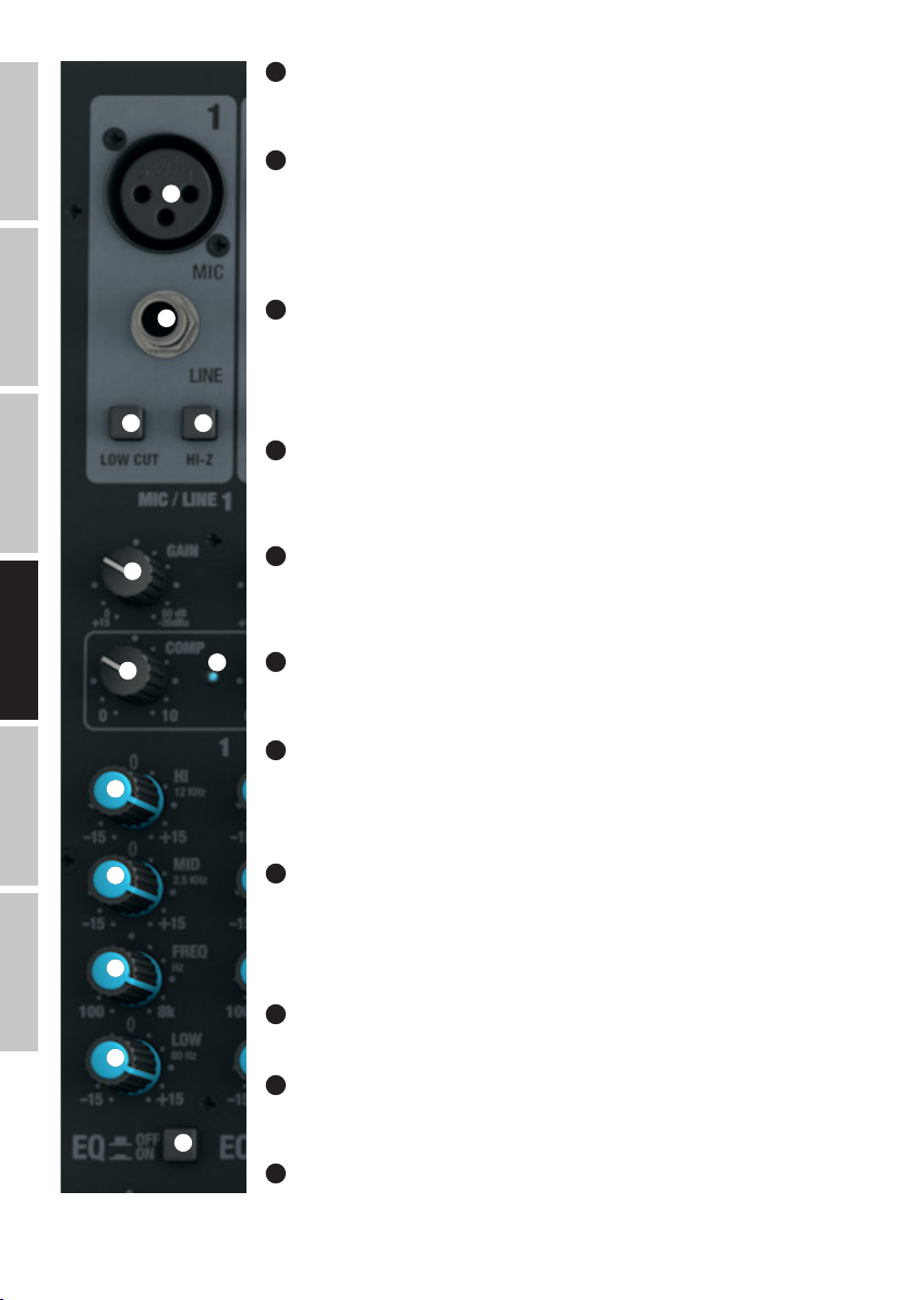
ENGLISH
DEUTSCHFRANCAIS
ESPAÑOL
14
15
16 17
18
19
12
AUX SEND 1-4
Salida de línea mono no balanceada con jacks de 6,3mm para enviar la señal a un procesador de efectos
externo (POST fader) o un monitor activo de escenario (PRE fader).
13
INSERT CH1 - CH8
Jacks estéreo de 6,3mm para insertar un equipo externo que procese la señal (compresor, puerta de ruido,
etc.) en uno de los canales1 a 8. Es necesario usar un cable especial (cable en Y, 1jack estéreo a 2jacks
mono o XLR). La asignación de pines es: punta= envío, anillo= retorno,malla = masa.
CANALES MONO 1-16
14
MIC (CANALES 1-16)
Entradas balanceadas de los canales1 a 16 con XLR hembra de 3pines para la conexión de micrófonos.
Para los micrófonos de condensador se puede aplicar una alimentación fantasma de 48V en el pin central
de los XLR (3). Antes de conectar o desconectar un micrófono, sitúe al mínimo el control de ganancia (18)
(girado completamente a la izquierda) y active la alimentación fantasma después de conectar un micrófono, o
desactívela antes de desconectarlo.
15
ENTRADA DE LÍNEA LINE (CANALES 1-16)
Entradas balanceadas de los canales mono1 a 16 con jack de 6,3mm para la conexión de equipos reproductores de nivel de línea. Antes de conectar o desconectar el jack, sitúe al mínimo el control de ganancia
(18) (girado completamente a la izquierda).
16
LOW CUT (CANALES 1-16)
Filtro paso altos para eliminar las señales de baja frecuencia no deseadas. Sobre todo con la voz y el canto,
al activar la función LOW CUT (botón pulsado) es posible disminuir el ruido de baja frecuencia y así mejorar la
inteligibilidad. La frecuencia de corte es 95Hz.
17
20
HI-Z (CANALES 1-4)
Al pulsar este botón, los jacks de entrada de los canales1 a 4 (CH1) pasan a alta impedancia. Esto permite
emplearlo como canal de instrumentos para una guitarra o un bajo eléctrico, por ejemplo.
ITALIANO POLSKI
60
18
GAIN (CANALES 1-16)
21
22
23
24
25
Permite ajustar la preamplificación de la entrada de micrófono entre 0 y 50dB, y la sensibilidad de la
entrada de línea entre +15 y −35dBu. Ajuste el control de ganancia de tal forma que el LED CLIP del canal
correspondiente solo se ilumine brevemente en los picos de la señal entrante. Para que el LED CLIP no esté
encendido de forma fija, disminuya la preamplificación o sensibilidad de entrada.
19
COMP (CANALES 1-8)
Compresor ajustable de forma continua de los canales1 a 8. En función del ajuste, la señal se comprime más
o menos, es decir, se reduce la dinámica de la señal (control girado completamente a la izquierda=
compresor desactivado; control girado completamente a la derecha = máxima compresión). Al ir aumentando
la compresión, el compresor va compensando automáticamente la pérdida de nivel. Por ejemplo, el
compresor puede mejorar la señal vocal en la señal de mezcla.
20
LED COMP
El LED se ilumina al activar el compresor.
21
ECUALIZADOR HI (CANALES 1-16)
Control de agudos de los canales1 a 16 (12kHz, +/-15dB). Girar a la izquierda para disminuir los agudos y a
la derecha para realzarlos. En la posición central de reposo, el control está inactivo.
22
ECUALIZADOR MID (CANALES 1-16)
Controles de medios de los canales1 a 16 (frecuencia ajustable, +/-15dB). Girar a la izquierda para disminuir
los medios y a la derecha para realzarlos. En la posición central de reposo, el control está inactivo.
Page 61
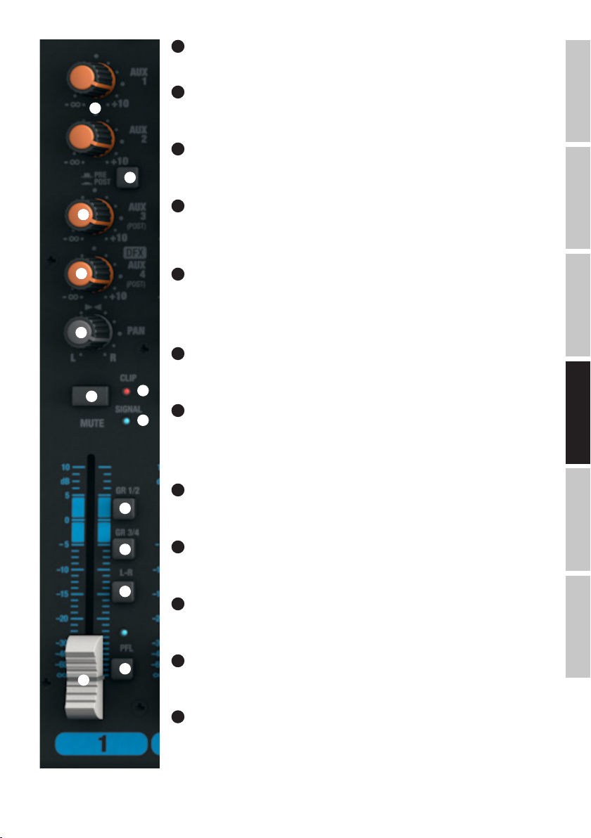
23
ECUALIZADOR MID FREQ (CANALES 1-16)
Frecuencia de la banda de medios. Ajuste la frecuencia de 200Hz a 8kHz.
24
ECUALIZADOR LOW (CANALES 1-16)
26
27
28
Controles de graves de los canales1 a 16 (80Hz, +/-15dB). Girar a la izquierda para disminuir los graves y a
la derecha para realzarlos. En la posición central de reposo, el control está inactivo.
25
EQ ON/OFF (CANALES 1-16)
Botón para activar o desactivar el ecualizador (HI, MID y LOW). Si el botón está pulsado, se activará el
ecualizador; en la posición sin pulsar, se desactivará el ecualizador.
26
AUX 1 + AUX 2 (CANALES 1-16)
Control de mezcla de la señal de los canales1 a 16 con la de un procesador de efectos externo (envío de
efecto, botón27 en POST), o para enviar la señal a un monitor activo de escenario (envío a monitor, botón27
en PRE). Use las salidas de línea AUX SEND1 y 2 (12) para enviar la señal.
29
30
31
35
36
37
38
32
27
AUX 1 + AUX 2 PRE/POST (CANALES 1-16)
Si está utilizando AUX1 o AUX2 para enviar la señal a un procesador de efectos externo, sitúe el botón en la
posición pulsada POST. La señal dependerá ahora del fader de canal (32). Para enviar la señal al monitor de
escenario, sitúe el botón en la posición PRE (sin pulsar). La señal no dependerá ahora del fader de canal (32)
y el volumen del monitor de escenario se podrá ajustar independientemente del nivel del canal.
28
AUX 3 POST (CANALES 1-16)
Control para mezclar la señal de los canales1 a 16 con el procesador de efectos externo (envío de efecto
postfader). Use la salida de línea AUX SEND3 (12) para enviar la señal.
34
29
33
NIVEL DFX / AUX 4 POST (CANALES 1-16)
Control para mezclar la señal de los canales1 a 16 con el procesador digital integrado (envío de efecto
postfader). Use la salida de línea AUX SEND4 (12) para enviar la señal a un procesador externo de efectos. Al
ocupar el jack AUX SEND4, se desactiva automáticamente el procesador interno de efectos y, por tanto, no
se puede utilizar.
30
PAN (CANALES 1-16)
El control Panorama permite posicionar la señal de cada canal en el campo estéreo de la señal de mezcla
(posición central= la señal se percibe en el centro del campo estéreo).
31
MUTE (CANALES 1-16)
Para silenciar un canal, pulse el botón MUTE del canal correspondiente. Al mismo tiempo, se iluminará el LED
MUTE del botón. Al desactivar la función de silencio, el LED MUTE se apagará.
32
FADER (CANALES 1-16)
Fader de los canales1 a 16. Deslice el fader hacia arriba para aumentar el nivel del canal, y hacia abajo para
disminuirlo.
33
LED DE SEÑAL (CANALES 1-16)
El LED se ilumina si hay señal de audio en la entrada del canal (depende del nivel de entrada y de la
preamplificación o sensibilidad de entrada GAIN).
FRANCAISDEUTSCHENGLISH
ITALIANOPOLSKIESPAÑOL
34
LED CLIP (CANALES 1-16)
Si el LED CLIP de una entrada se ilumina de color rojo, el canal está saturando. Ajuste el control de ganancia
(18) de tal forma que el LED CLIP solo se ilumine brevemente en los picos de la señal entrante. Para que el
LED CLIP no esté encendido de forma fija, disminuya la preamplificación o sensibilidad de entrada, y si es
necesario, baje el nivel del equipo reproductor.
61
Page 62

35
GR 1/2 (CANALES 1-16)
Sitúe en la posición pulsada el botón GR 1/2 de un canal para añadirlo al grupo1 de canales (PAN girado completamente a la izquierda), al grupo2
de canales (PAN girado completamente a la derecha), o para enviar la misma señal a los grupos1 y 2 a la vez (PAN en la posición intermedia).
Además, se envía la señal de un grupo de canales a la salida de línea GROUP OUT 1/2. El nivel global de los grupos se ajusta mediante el fader
GROUP1/2 (104); si desea enviar la señal de audio del grupo al canal de mezcla MAIN MIX, deje pulsado el botón L-R (105).
ENGLISH
36
GR 3/4 (CANALES 1-16)
Sitúe en la posición pulsada el botón GR 3/4 de un canal para añadirlo al grupo3 de canales (PAN girado completamente a la izquierda), al grupo4
de canales (PAN girado completamente a la derecha), o para enviar la misma señal a los grupos3 y 4 a la vez (PAN en la posición intermedia).
Además, se envía la señal de un grupo de canales a la salida de línea GROUP OUT 3/4. El nivel global de los grupos se ajusta mediante el fader
GROUP3/4 (106); si desea enviar la señal de audio del grupo al canal de mezcla MAIN MIX, deje pulsado el botón L-R (107).
37
L-R (CANALES 1-16)
DEUTSCHFRANCAIS
Para enviar directamente un canal de entrada (canales1 a 16) al canal de mezcla MAIN MIX, deje pulsado el botón de L-R del canal.
38
PFL (CANALES 1-16)
Pulse el botón PFL (Pre Fader Listen) de un canal, primero, para que a través de los cascos conectados a la salida de auriculares PHONES (82), nos
llegue la señal de dicho canal independientemente de la posición del fader de canal (32) y, segundo, para realizar un ajuste preciso de la ganancia,
ya que el nivel de la señal de entrada se mostrará en el vúmetro de 12LED del canal de mezcla MAIN MIX. Al mismo tiempo, se iluminarán los LED
PFL del canal y PFL del canal de mezcla MAIN MIX. Cuando el botón PFL vuelve a su posición original (sin pulsar), los LED PFL se apagarán.
ESPAÑOL
ITALIANO POLSKI
62
Page 63

CANALES ESTÉREO 17/18 Y 19/20
39
MIC (CANALES 17/18 + 19/20)
Entradas balanceadas de los canales17/18 y 19/20 con XLR hembra de 3pines para la conexión de
micrófonos. Los canales17/18 y 19/20 pueden emplearse como mono o como estéreo (XLR y jack L=
entrada mono; jack L y R= entrada estéreo). Para los micrófonos de condensador se puede aplicar una
39
alimentación fantasma de 48V en el pin central de los XLR (3). Antes de conectar o desconectar un
micrófono, sitúe al mínimo el control de ganancia (41) (girado completamente a la izquierda) y active la
alimentación fantasma después de conectar un micrófono, o desactívela antes de desconectarlo.
40
ENTRADA DE LÍNEA L/R (CANALES 17/18 + 19/20)
Entradas no balanceadas de los canales estéreo17/18 y 19/20 con jack de 6,3mm para la conexión de
equipos reproductores de nivel de línea, como un teclado. Si solo se ocupa la entrada izquierda (L), el canal
funcionará en mono.
40
41
42
43
44
41
GAIN (CANALES 17/18 + 19/20)
Permite ajustar la preamplificación de la entrada de micrófono entre 0 y 50dB, y la sensibilidad de la
entrada de línea entre +15 y −35dBu. Ajuste el control de ganancia de tal forma que el LED CLIP del canal
correspondiente solo se ilumine brevemente en los picos de la señal entrante. Para que el LED CLIP no esté
encendido de forma fija, disminuya la preamplificación o sensibilidad de entrada, y si es necesario, baje el
nivel del equipo reproductor.
42
ECUALIZADOR HI (CANALES 17/18 + 19/20)
Control de agudos de los canales17/18 y 19/20 (12kHz, +/-15dB). Girar a la izquierda para disminuir los
agudos y a la derecha para realzarlos. En la posición central de reposo, el control está inactivo.
42
ECUALIZADOR HI (CANALES 17/18 + 19/20)
Control de agudos de los canales17/18 y 19/20 (12kHz, +/-15dB). Girar a la izquierda para disminuir los
agudos y a la derecha para realzarlos. En la posición central de reposo, el control está inactivo.
43
ECUALIZADOR MID HI (CANALES 17/18 + 19/20)
Controles de medios altos de los canales17/18 y 19/20 (3kHz, +/-15dB). Girar a la izquierda para disminuir
los medios altos y a la derecha para realzarlos. En la posición central de reposo, el control está inactivo.
44
ECUALIZADOR MID LOW (CANALES 17/18 + 19/20)
Controles de medios bajos de los canales17/18 y 19/20 (500Hz, +/-15dB). Girar a la izquierda para
disminuir los medios bajos y a la derecha para realzarlos. En la posición central de reposo, el control está
inactivo.
45
ECUALIZADOR LOW (CANALES 17/18 + 19/20)
Control de graves de los canales17/18 y 19/20 (80Hz, +/-15dB). Girar a la izquierda para disminuir los
graves y a la derecha para realzarlos. En la posición central de reposo, el control está inactivo.
46
EQ ON/OFF (CANALES 17/18 + 19/20)
Botón para activar o desactivar el ecualizador (HI, MID HI, MID LOW y LOW). Si el botón está pulsado, se
activará el ecualizador; en la posición sin pulsar, se desactivará el ecualizador.
FRANCAISDEUTSCHENGLISH
ITALIANOPOLSKIESPAÑOL
45
46
47
AUX 1 + AUX 2 (CANALES 17/18 + 19/20)
Control de mezcla de la señal de los canales17/18 y 19/20 con la de un procesador de efectos externo
(envío de efecto, botón48 en POST), o para enviar la señal a un monitor activo de escenario (envío a monitor,
botón48 en PRE). Use las salidas de línea AUX SEND1 y 2 (12) para enviar la señal.
63
Page 64

ENGLISH
DEUTSCHFRANCAIS
48
AUX 1 + AUX 2 PRE/POST (CANALES 17/18 + 19/20)
Si está utilizando AUX1 o AUX2 para enviar la señal a un procesador de efectos externo, sitúe el botón en la
posición pulsada POST. La señal dependerá ahora del fader de canal (53). Para enviar la señal al monitor de
escenario, sitúe el botón en la posición PRE (sin pulsar). La señal no dependerá ahora del fader de canal (53)
47
48
49
50
y el volumen del monitor de escenario se podrá ajustar independientemente del nivel del canal.
49
AUX 3 POST (CANALES 17/18 + 19/20)
Control para mezclar la señal de los canales17/18 y 19/20 con el procesador de efectos externo (envío de
efecto postfader). Use la salida de línea AUX SEND3 (12) para enviar la señal.
50
NIVEL DFX / AUX 4 POST (CANALES 17/18 + 19/20)
Control para mezclar la señal de los canales17/18 y 19/20 con el procesador digital integrado (envío de
efecto postfader). Use la salida de línea AUX SEND4 (12) para enviar la señal a un procesador externo de
efectos. Al ocupar el jack AUX SEND4, se desactiva automáticamente el procesador interno de efectos y, por
tanto, no se puede utilizar.
51
BAL (CANALES 17/18 + 19/20)
Este control BALANCE ajusta el balance de nivel entre los canales izquierdo y derecho de la señal estéreo. Si
solo se ocupa el XLR o el jack izquierdo L (MONO) de la entrada de línea de los canales17/18 y 19/20, este
control funcionará como un Panorama.
ESPAÑOL
ITALIANO POLSKI
51
52
56
57
58
59
53
52
MUTE (CANALES 17/18 + 19/20)
Para silenciar un canal, pulse el botón MUTE del canal correspondiente. Al mismo tiempo, se iluminará el LED
MUTE del botón. Al desactivar la función de silencio, el LED MUTE se apagará.
53
55
54
FADER (CANALES 17/18 + 19/20)
Fader de los canales17/18 y 19/20. Deslice el fader hacia arriba para aumentar el nivel del canal, y hacia
abajo para disminuirlo.
54
LED DE SEÑAL (CANALES 17/18 + 19/20)
El LED se ilumina si hay señal de audio en la entrada del canal (depende del nivel de entrada y de la
preamplificación o sensibilidad de entrada GAIN).
55
LED CLIP (CANALES 17/18 + 19/20)
Si el LED CLIP de una entrada se ilumina de color rojo, el canal está saturando. Ajuste el control de ganancia
(41) de tal forma que el LED CLIP solo se ilumine brevemente en los picos de la señal entrante. Para que el
LED CLIP no esté encendido de forma fija, disminuya la preamplificación o sensibilidad de entrada, y si es
necesario, baje el nivel del equipo reproductor.
56
GR 1/2 (CANALES 17/18 + 19/20)
Sitúe en la posición pulsada el botón GR 1/2 de un canal para añadirlo al grupo1 de canales (BAL girado
completamente a la izquierda), al grupo2 de canales (BAL girado completamente a la derecha), o para enviar
la misma señal a los grupos1 y 2 a la vez (BAL en la posición intermedia). Además, se envía la señal de un
grupo de canales a la salida de línea GROUP OUT 1/2. El nivel global de los grupos se ajusta mediante el fader
GROUP1/2 (104); si desea enviar la señal de audio del grupo al canal de mezcla MAIN MIX, deje pulsado el
botón L-R (105).
57
GR 3/4 (CANALES 17/18 + 19/20)
Sitúe en la posición pulsada el botón GR 3/4 de un canal para añadirlo al grupo3 de canales (BAL girado
completamente a la izquierda), al grupo4 de canales (BAL girado completamente a la derecha), o para enviar
la misma señal a los grupos3 y 4 a la vez (BAL en la posición intermedia). Además, se envía la señal de un
grupo de canales a la salida de línea GROUP OUT 3/4. El nivel global de los grupos se ajusta mediante el fader
GROUP3/4 (106); si desea enviar la señal de audio del grupo al canal de mezcla MAIN MIX, deje pulsado el
botón L-R (107).
64
Page 65

58
L-R (CANALES 17/18 + 19/20)
Para enviar directamente un canal de entrada (canales17/18 y 19/20) al canal de mezcla MAIN MIX, deje
pulsado el botón de L-R del canal.
59
PFL (CANALES 17/18 + 19/20)
60
Pulse el botón PFL (Pre Fader Listen) de un canal, primero, para que a través de los cascos conectados a la
salida de auriculares PHONES (82), nos llegue la señal de dicho canal independientemente de la posición del
fader de canal (53) y, segundo, para realizar un ajuste preciso del a ganancia, ya que el nivel de la señal de
entrada se mostrará en el vúmetro de 12LED del canal de mezcla MAIN MIX. Al mismo tiempo, se iluminarán
los LED PFL del canal y PFL del canal de mezcla MAIN MIX. Cuando el botón PFL vuelve a su posición original
(sin pulsar), los LED PFL se apagarán.
CANALES ESTÉREO 21/22 Y 23/24
61
60
ENTRADA DE LÍNEA L/R (CANALES 21/22 + 23/24)
Entrada de línea no balanceada L y R por RCA.
61
GAIN (CANALES 21/22 + 23/24)
62
63
64
65
66
67
Permite ajustar la ganancia de la entrada de línea, de +15 a −35dBu. Ajuste el control de ganancia de tal forma que el LED CLIP del canal correspondiente solo se ilumine brevemente en los picos de la señal entrante.
Para que el LED CLIP no esté encendido de forma fija, disminuya la sensibilidad de entrada y, si es necesario,
baje el nivel del equipo reproductor.
62
LINE/USB 21/22
Conmuta la fuente de señal para el canal estéreo 21/22. En la posición sin pulsar se seleccionan los conectores RCA como fuente de señal, mientras que en la posición pulsada se selecciona el puerto USB del panel
posterior de la mesa de mezclas.
63
ECUALIZADOR HI (CANALES 21/22 + 23/24)
Control de agudos de los canales21/22 y 23/24 (12kHz, +/-15dB). Girar a la izquierda para disminuir los
agudos y a la derecha para realzarlos. En la posición central de reposo, el control está inactivo.
64
ECUALIZADOR MID HI (CANALES 21/22 + 23/24)
Controles de medios altos de los canales21/22 y 23/24 (3kHz, +/-15dB). Girar a la izquierda para disminuir
los medios altos y a la derecha para realzarlos. En la posición central de reposo, el control está inactivo.
65
ECUALIZADOR MID LOW (CANALES 21/22 + 23/24)
Controles de medios bajos de los canales21/22 y 23/24 (500Hz, +/-15dB). Girar a la izquierda para disminuir los medios bajos y a la derecha para realzarlos. En la posición central de reposo, el control está inactivo.
66
ECUALIZADOR LOW (CANALES 21/22 + 23/24)
Control de graves de los canales21/22 y 23/24 (80Hz, +/-15dB). Girar a la izquierda para disminuir los
graves y a la derecha para realzarlos. En la posición central de reposo, el control está inactivo.
67
EQ ON/OFF (CANALES 21/22 + 23/24)
Botón para activar o desactivar el ecualizador (HI, MID HI, MID LOW y LOW). Si el botón está pulsado, se
activará el ecualizador; en la posición sin pulsar, se desactivará el ecualizador.
FRANCAISDEUTSCHENGLISH
ITALIANOPOLSKIESPAÑOL
68
AUX 1 + AUX 2 (CANALES 21/22 + 23/24)
Control de mezcla de la señal de los canales21/22 y 23/24 con la de un procesador de efectos externo
(envío de efecto, botón69 en POST), o para enviar la señal a un monitor activo de escenario (envío a monitor,
botón69 en PRE). Use las salidas de línea AUX SEND1 y 2 (12) para enviar la señal.
65
Page 66
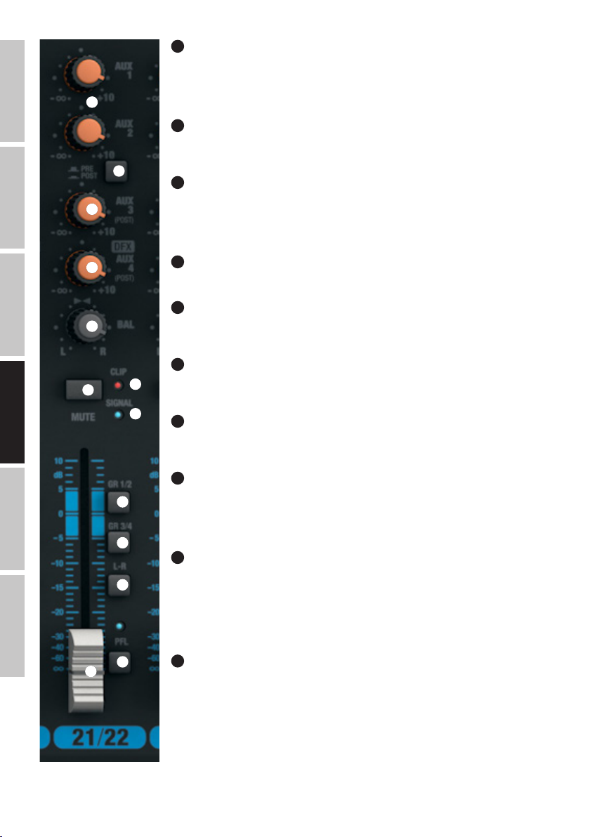
ENGLISH
DEUTSCHFRANCAIS
ESPAÑOL
69
AUX 1 + AUX 2 PRE/POST (CANALES 21/22 + 23/24)
Si está utilizando AUX1 o AUX2 para enviar la señal a un procesador de efectos externo, sitúe el botón en la
posición pulsada POST. La señal dependerá ahora del fader de canal (74). Para enviar la señal al monitor de
escenario, sitúe el botón en la posición PRE (sin pulsar). La señal no dependerá ahora del fader de canal (74)
68
69
70
71
72
73
y el volumen del monitor de escenario se podrá ajustar independientemente del nivel del canal.
70
AUX 3 POST (CANALES 21/22 + 23/24)
Control para mezclar la señal de los canales21/22 y 23/24 con el procesador de efectos externo (envío de
efecto postfader). Use la salida de línea AUX SEND3 (12) para enviar la señal.
71
NIVEL DFX / AUX 4 POST (CANALES 21/22 + 23/24)
Control para mezclar la señal de los canales21/22 y 23/24 con el procesador digital integrado (envío de
efecto postfader). Use la salida de línea AUX SEND4 (12) para enviar la señal a un procesador externo de
efectos. Al ocupar el jack AUX SEND4, se desactiva automáticamente el procesador interno de efectos y, por
tanto, no se puede utilizar.
72
BAL (CANALES 21/22 + 23/24)
Este control BALANCE ajusta el balance de nivel entre los canales izquierdo y derecho de la señal estéreo.
73
MUTE (CANALES 21/22 + 23/24)
Para silenciar un canal, pulse el botón MUTE del canal correspondiente. Al mismo tiempo, se iluminará el LED
MUTE del botón. Al desactivar la función de silencio, el LED MUTE se apagará.
74
FADER (CANALES 21/22 + 23/24)
Fader de los canales21/22 y 23/24. Deslice el fader hacia arriba para aumentar el nivel del canal, y hacia
76
abajo para disminuirlo.
75
75
LED DE SEÑAL (CANALES 21/22 + 23/24)
El LED se ilumina si hay señal de audio en la entrada del canal (depende del nivel de entrada y de la
preamplificación o sensibilidad de entrada GAIN).
ITALIANO POLSKI
66
76
LED CLIP (CANALES 21/22 + 23/24)
77
78
79
80
74
Si el LED CLIP de una entrada se ilumina de color rojo, el canal está saturando. Ajuste el control de ganancia
(61) de tal forma que el LED CLIP solo se ilumine brevemente en los picos de la señal entrante. Para que el
LED CLIP no esté encendido de forma fija, disminuya la preamplificación o sensibilidad de entrada, y si es
necesario, baje el nivel del equipo reproductor.
77
GR 1/2 (CANALES 21/22 + 23/24)
Sitúe en la posición pulsada el botón GR 1/2 de un canal para añadirlo al grupo1 de canales (BAL girado
completamente a la izquierda), al grupo2 de canales (BAL girado completamente a la derecha), o para enviar
la misma señal a los grupos1 y 2 a la vez (BAL en la posición intermedia). Además, se envía la señal de un
grupo de canales a la salida de línea GROUP OUT 1/2. El nivel global de los grupos se ajusta mediante el fader
GROUP1/2 (104); si desea enviar la señal de audio del grupo al canal de mezcla MAIN MIX, deje pulsado el
botón L-R (105).
GR 3/4 (CANALES 21/22 + 23/24)
78
Sitúe en la posición pulsada el botón GR 3/4 de un canal para añadirlo al grupo3 de canales (BAL girado
completamente a la izquierda), al grupo4 de canales (BAL girado completamente a la derecha), o para enviar
la misma señal a los grupos3 y 4 a la vez (BAL en la posición intermedia). Además, se envía la señal de un
grupo de canales a la salida de línea GROUP OUT 3/4. El nivel global de los grupos se ajusta mediante el fader
GROUP3/4 (106); si desea enviar la señal de audio del grupo al canal de mezcla MAIN MIX, deje pulsado el
botón L-R (107).
Page 67

79
L-R (CANALES 21/22 + 23/24)
Para enviar directamente un canal de entrada (canales21/22 y 23/24) al canal de
mezcla MAIN MIX, deje pulsado el botón de L-R del canal.
81
83
82
80
PFL (CANALES 21/22 + 23/24)
Pulse el botón PFL (Pre Fader Listen) de un canal, primero, para que a través de los
cascos conectados a la salida de auriculares PHONES (82) nos llegue la señal de dicho
canal independientemente de la posición del fader de canal (74) y, segundo, para
realizar un ajuste preciso de la ganancia, ya que el nivel de la señal de entrada se
mostrará en el vúmetro de 12LED del canal de mezcla MAIN MIX (mediante el control
GAIN correspondiente, reduzca el nivel de la señal de entrada cuando se ilumine el
LED CLIP). Al mismo tiempo, se iluminarán los LED PFL del canal y PFL del canal de
mezcla MAIN MIX. Cuando el botón PFL vuelve a su posición original (sin pulsar), los
LED PFL se apagarán.
84
87
88
90
91
92
93 95
94 97
108
109
85
86
89
98
99
95
100
101
103
102
111
SECCIÓN MASTER
81
POWER LAMP
Conector USB de tipo A para conectar una lámpara. Asegúrese de que coinciden las
especificaciones del conector y la lámpara (5VDC, 500mA máximo).
82
SALIDA DE AURICULARES
Jack estéreo de 6,3mm para conectar los auriculares. En este conector se pueden
monitorar varias señales:
A. Botón100 (CTRL ROOM SOURCE MAIN/GR) sin pulsar y botón PFL sin pulsar: señal
de mezcla MAIN MIX.
B. Botón100 pulsado y botón PFL sin pulsar: señal de grupos GROUP GR1/2 o GR3/4
(según el botón101 GR1/2 / GR3/4).
C. Uno o varios botones PFL pulsados de los canales de entrada: escucha prefader del
o los canales correspondientes con toma antes del fader de canal.
83
STEREO GRAPHIC EQ
Ecualizador gráfico de 7 bandas del canal de mezcla MAIN MIX.
84
EQ ON/OFF
Botón para activar o desactivar el ecualizador (83). Si el botón está pulsado, se
activará el ecualizador; en la posición sin pulsar, se desactivará el ecualizador.
85
LED +48V
Si está activada la alimentación fantasma de la mesa de mezclas, se iluminará el LED
+48V (conmutador3 del panel posterior).
86
LED POWER
El LED POWER se ilumina cuando la mesa de mezclas está encendida y enchufada
correctamente a la red eléctrica.
FRANCAISDEUTSCHENGLISH
ITALIANOPOLSKIESPAÑOL
105
104 106 110
107
87
PANTALLA DFX PRESETS
Pantalla LED de 2 dígitos que indica el número de preset (00 - 99).
88
DFX PRESETS (PUSH)
Control giratorio para seleccionar y activar los presets. Gire el control para seleccionar
un preset y pulse el control para activarlo.
67
Page 68

89
DFX PRESETS LIST
Lista de los efectos digitales disponibles.
90
LED PEAK DFX
Si el LED PEAK de una entrada se ilumina de color rojo, la entrada del procesador interno de efectos está saturando. Ajuste el control de nivel de
ENGLISH
envío de efecto DFX SEND AUX4 (94) de tal forma que el LED PEAK solo se ilumine brevemente en los picos de la señal entrante.
91
DFX MUTE
Para silenciar el procesador interno de efectos, pulse brevemente el botón MUTE DFX; pulse de nuevo para desactivar la función de silencio. Si el
procesador de efectos está desactivado, el LED PEAK (90) se iluminará de forma continua.
92
SEND AUX 1 + AUX 2
DEUTSCHFRANCAIS
Control de nivel general de la señal regulada por los controles AUX1 y AUX2 de los canales de entrada 1 a 23/24.
93
SEND AUX 3
Control de nivel general de la señal regulada por los controles AUX3 de los canales de entrada 1 a 23/24.
94
SEND AUX 4 / DFX
Control de nivel general de la señal regulada por los controles AUX4 / DFX de los canales de entrada 1 a 23/24 (procesador interno o externo de
efectos).
95
DFX TO AUX 1 + AUX 2
Control de nivel para mezclar la señal de efecto del procesador interno de efectos con los buses AUX1 y AUX2.
96
DFX OUT
Control de nivel de la señal de envío en las salidas DFX OUT.
ESPAÑOL
97
DFX TO MAIN
Control de nivel para mezclar la señal de efecto del procesador interno de efectos con el canal de mezcla MAIN MIX.
98
OUTPUT LEVEL
Doble vúmetro LED de 12segmentos que muestra el nivel del canal estéreo de mezcla MAIN MIX y que permite realizar un ajuste preciso de la
ganancia, ya que el nivel de la señal de entrada se monitoriza en el vúmetro de LED cuando se pulsa el botón PFL del canal correspondiente. Para
evitar distorsiones, en cuanto se ilumine el LED CLIP de color rojo, reduzca el nivel de salida con el fader MAIN MIX (110), o bien, reduzca el nivel de
la señal de entrada mediante el control de ganancia GAIN correspondiente.
99
LED PFL
El LED PFL se ilumina cuando hay pulsados uno o varios botones PFL de los canales de entrada1 a 23/24.
100
MAIN / GR (CTRL ROOM SOURCE)
Botón para seleccionar la fuente de señal para la salida de monitorado de sala CTRL ROOM (10) y de auriculares (82). En la posición sin pulsar, se
envía la señal de mezcla MAIN MIX, mientras que en la posición pulsada se envía la señal de grupos GR1/2 o GR3/4, en función del botón GR1/2
ITALIANO POLSKI
/ GR3/4 (101).
101
GR1/2 / GR3/4 (CTRL ROOM SOURCE)
Si el botón MAIN / GR de la sección CTRL ROOM SOURCE (100) está pulsado, se elige si se envía la señal de grupos GR1/2 o la GR3/4 (con el
botón sin pulsar= GR1/2, botón pulsado= GR3/4).
102
NIVEL CTRL ROOM
Control de volumen para la salida de línea estéreo de monitorado de sala CTRL ROOM (10). Antes de encender el altavoz de monitorado que haya
conectado, sitúe este control al mínimo.
68
Page 69

103
NIVEL DE AURICULARES
Control de volumen para los auriculares (82). Emplee unos auriculares con una impedancia mínima de 30ohmios y asegúrese de mantener el volumen en un nivel adecuado que evite daños auditivos debido a niveles sonoros altos. Antes de conectar los auriculares, sitúe este control al mínimo.
104
GROUP 1/2
Fader para las salidas de línea GROUP OUT1 y 2 (11) y, si el botón GROUP1/2 L-R está pulsado (105), para la mezcla de la señal de grupos
GROUP1/2 con el canal de mezcla MAIN MIX. Antes de encender el sistema de refuerzo sonoro que haya conectado, sitúe este fader al mínimo.
105
L-R (GROUP 1/2)
Botón para enviar la señal de grupos GROUP1/2 al canal de mezcla MAIN MIX (posición pulsada).
106
GROUP 3/4
Fader para la salidas de línea GROUP OUT3 y 4 (11) y, si el botón GROUP3/4 L-R está pulsado (107), para la mezcla de la señal de grupos
GROUP3/4 con el canal de mezcla MAIN MIX. Antes de encender el sistema de refuerzo sonoro que haya conectado, sitúe este fader al mínimo.
107
L-R (GROUP 3/4)
Botón para enviar la señal de grupos GROUP3/4 al canal de mezcla MAIN MIX (posición pulsada).
108
MUTE (GROUP 1/2)
Para silenciar la señal de grupos GROUP1/2, deje pulsado este botón. Al mismo tiempo, se iluminará el LED MUTE del botón. Al desactivar la
función de silencio, el LED MUTE se apagará.
109
MUTE (GROUP 3/4)
Para silenciar la señal de grupos GROUP3/4, deje pulsado este botón. Al mismo tiempo, se iluminará el LED MUTE del botón. Al desactivar la
función de silencio, el LED MUTE se apagará.
110
MAIN MIX
Fader para las salidas de línea estéreo MAIN MIX OUTPUT (5) y (6). Deslice el fader hacia arriba para aumentar el nivel, y hacia abajo para
disminuirlo. Antes de encender el sistema de refuerzo sonoro que haya conectado, sitúe este fader al mínimo.
FRANCAISDEUTSCHENGLISH
111
MUTE (MAIN MIX)
Para silenciar la señal de mezcla MAIN MIX, deje pulsado este botón. Al mismo tiempo, se iluminará el LED MUTE del botón. Al desactivar la función
de silencio, el LED MUTE se apagará.
ITALIANOPOLSKIESPAÑOL
69
Page 70

INSTALACIÓN DEL PUERTO USB
Instalación en sistemas operativos Windows (Windows XP® o superior):
Para la instalación no es necesario descargar ningún controlador en una unidad de almacenamiento externo. Conecte la mesa de mezclas
mediante el cable USB suministrado a un puerto USB2.0 del ordenador. Casi siempre, la instalación del software se realizará automáticamente. Si
ENGLISH
es necesario, reinicie el ordenador. Es posible que se abra un cuadro de diálogo (Instalación de software del dispositivo) solicitándole que instale
el software USB Audio CODEC. Acepte dicho cuadro de diálogo. En el «Administrador de dispositivos» de su sistema operativo, el mezclador se
mostrará en la rama «Controladoras de sonido y vídeo y dispositivos de juego» como «USB Audio CODEC» o «Dispositivo de audio USB», y ya podrá
usarlo. Dependiendo del software de grabación empleado, puede ser necesario seleccionar el mezclador en el panel de control «Sonido» («Panel de
control»→«Hardware y sonido»→«Sonido») como un dispositivo de grabación o reproducción.
Instalación en sistemas operativos Apple (Mac OS X® 10.5 o superior):
Para la instalación no es necesario descargar ningún controlador en una unidad de almacenamiento externo. Conecte la mesa de mezclas mediante
el cable USB suministrado a un puerto USB2.0 del ordenador. La instalación del software se realizará automáticamente. Dependiendo del software
DEUTSCHFRANCAIS
de grabación empleado, puede ser necesario seleccionar el mezclador (USB Audio CODEC) en el panel de control «Sonido» («Preferencias del
sistema»→«Sonido») como un dispositivo de entrada o salida.
CARACTERÍSTICAS TÉCNICAS
Nombre del modelo: LDVIBZ24DC
Tipo de producto: Mesa de mezclas analógica
Tipo: Grabación en directos/casa
Número de canales: 24
Canales mono:
Canales de entrada mono de micro/línea: 16
Conectores de entrada mono de micro/línea: Jack estéreo de 6,3 mm, XLR
Tipo de entrada mono de micro: Balanceada electrónicamente, tecnología discreta
Respuesta en frecuencia de la entrada mono
ESPAÑOL
de micro:
Ganancia de la entrada mono de micro: 50 dB
Diafonía entre canales: 90 dB
THD de la entrada mono de micro: 0,0058%
Impedancia de la entrada mono de micro: 4 Kohmios
Relación señal/ruido de la entrada mono de
micro:
Tipo de entrada mono de línea: Balanceada electrónicamente, tecnología discreta
Ganancia de la entrada mono de línea: 50 dB
THD de la entrada mono de línea: 0,0045%
Impedancia de la entrada mono de línea: 21 Kohmios
Relación señal/ruido de la entrada mono de línea: 116 dB
Ecualizador de agudos del canal mono: +/-15 dB a 12 kHz
Ecualizador de medios del canal mono: +/-15 dB (200 Hz - 8 kHz)
Ecualizador de graves del canal mono: +/-15 dB a 80 Hz
ITALIANO POLSKI
Canal Insert: Canales 1 a 8
Conectores del canal Insert: Jack estéreo de 6,3 mm (PUNTA = envío, ANILLO = retorno)
Alimentación fantasma: +48 VDC conmutables en XLR de entrada
Filtro paso altos: 95 Hz
Hi-Z: Jack de los canales de entrada 1 - 4, conmutables (> 50 Kohmios)
Compresor: Canales 1 a 8
Controles de canales 1 - 16: Gain, Low Cut, High-Z (canales1 - 4), compresor (canales1 - 8), EQ Hi, EQ Mid, EQ
10 - 45.000 Hz
113 dB
Mid Freq, EQ Low, EQ on/off, DFX, AUX Send1-2 pre (AUX2 conmutable pre/post), AUX
Send3-4 post, Mute de canal, botones de envío de fader (Group1/2, Group3/4, Main
L+R), Pan/Bal, fader de canales, botón PFL
70
Page 71

Canales estéreo:
Canales de entrada estéreo de línea: 4
Conectores de entrada estéreo de línea: 2 jacks estéreo de 6,3 mm (L mono, R), 2 RCA (Cinch)
Tipo de entrada estéreo de línea: No balanceada
Conector de USB IN/OUT: USB tipo B (canales 21/22)
Respuesta en frecuencia de la entrada estéreo
de línea:
Ganancia de la entrada estéreo de línea: 50 dB
Diafonía entre canales: 62 dB
THD de la entrada estéreo de línea: 0,0045%
Impedancia de la entrada estéreo de línea: 3,7 Kohmios
Relación señal/ruido de la entrada estéreo de
línea:
Ecualizador de agudos del canal estéreo: +/-15 dB a 12 kHz
Ecualizador de medios altos del canal estéreo: +/-15 dB a 3 kHz
Ecualizador de medios bajos del canal estéreo: +/-15 dB a 500 Hz
Ecualizador de graves del canal estéreo: +/-15 dB a 80 Hz
Controles de canales 17/18 - 23/24: Gain, botón LINE/USB (canales21/22), EQ Hi, EQ Mid, EQ Mid Freq, EQ Low, EQ on/
Sección master:
Canales de envío de efecto/AUX: 4
Conectores de envío de efecto/AUX: 4 jacks estéreo de 6,3 mm, no balanceado
Salidas estéreo principales balanceadas: 2
Conectores de salida estéreo principal balancea-
da/no balanceada:
Impedancia de la salida estéreo principal
balanceada:
Nivel máximo de la salida estéreo principal
balanceada (no balanceada):
Salidas estéreo de monitorado: 1
Conectores de salida estéreo de monitorado: 2 jacks de 6,3 mm
Salidas de grupos (GR OUT): 4
Conectores de salida de grupos: 4 jacks de 6,3 mm
Salida de auriculares: 1
Conectores de salida para auriculares: Jack estéreo de 6,3 mm
Impedancia mínima de auriculares: 30 ohmios
Procesador de efectos digital: Sí
Efectos preprogramados: 100
Conector para pedal DFX MUTE: Jack de 6,3mm (el pedal es un accesorio opcional)
Controles de la sección master: Ecualizador gráfico de 7bandas, EQ On/Off, DFX Presets, DFX Mute, AUX/DFX Send1
10 - 45.000 Hz
116 dB
off, DFX, AUX Send1-2 pre (AUX2 conmutable pre/post), AUX Send3-4 post, Mute
de canal, botones de envío de fader (Group1/2, Group3/4, Main L+R), Bal, fader de
canales, botón PFL
2 jacks estéreo de 6,3 mm, 2 XLR macho
120 ohmios
22 dBu (20 dBV)
- 4, DFX to Main, DFX to Aux, Phones, CTRL, botón GROUP to Main, alimentación fantasma de +48V, fader MAIN MIX, fader Group, LED Power, CTRL Room Source MAIN/
GR, GR1/2 - GR3/4, Group Mute, Main Mute
FRANCAISDEUTSCHENGLISH
ITALIANOPOLSKIESPAÑOL
71
Page 72
Especificaciones generales:
Indicadores: LED de picos, señal y PFL en cada canal, picos en la sección de efectos, encendido,
Conector para la lámpara: USB-A, 5 VDC, 500 mA máx.
USB IN/OUT: USB 2.0, conversor Delta-Sigma de 16 bits
ENGLISH
Conexión de alimentación eléctrica: IEC
Alimentación eléctrica: 100 - 240 VAC, 50/60 Hz
Consumo (máx.): 70 W
Fusible: T1,6AL / 250V
Rango de temperatura operativa: 0 a +45 °C
Rango de humedad operativa: 10% - 80% relativa, sin condensación
DEUTSCHFRANCAIS
Ancho: 712 mm
Altura: 80 mm
Fondo: 425 mm
Peso: 9,36 kg
alimentación fantasma, Mute, pantalla LED DFX, vúmetro doble de 12segmentos
D/A: 32 kHz, 44,1 kHz, 48 kHz
A/D: 8 kHz, 11,025 kHz, 16 kHz, 22,05 kHz, 32 kHz, 44,1 kHz, 48 kHz
DECLARACIÓN DEL FABRICANTE
GARANTÍA DEL FABRICANTE Y LIMITACIÓN DE RESPONSABILIDAD
Consulte nuestras condiciones de garantía y limitaciones de responsabilidad en: http://www.adamhall.com/media/shop/downloads/documents/
manufacturersdeclarations.pdf. En caso de necesitar servicio técnico, póngase en contacto con Adam Hall GmbH, Daimlerstraße 9, 61267 Neu
Anspach (Alemania); correo electrónico Info@adamhall.com; +49 (0)6081 / 9419-0. Puede solicitar la declaración de conformidad enviando un
mensaje a info@adamhall.com.
ELIMINACIÓN CORRECTA DE ESTE PRODUCTO
(Aplicable en la Unión Europea y en los países europeos que dispongan de un sistema de recogida selectiva) El símbolo que aparece
sobre el producto o en la documentación adjunta indica que al final de la vida útil del equipo, no deberá desecharlo con los demás
residuos domésticos, con el fin de evitar posibles efectos negativos en el medio ambiente y en la salud humana debidos al vertido
ESPAÑOL
incontrolado de desechos. La recogida selectiva ayuda a su posterior reciclaje y fomenta la reutilización sostenible de los componentes de
este equipo. Si es un particular, póngase en contacto con el distribuidor donde adquirió este producto, o con el ayuntamiento, para
informarse sobre el reciclaje adecuado de este equipo. Si es una empresa, póngase en contacto con su proveedor para informarse sobre los
términos y condiciones de su contrato de compra-venta. Este producto no debe mezclarse con otros residuos industriales.
ITALIANO POLSKI
72
Page 73

POLSKI
GRATULUJEMY WYBORU!
To urządzenie zostało zaprojektowane i wyprodukowane przy zastosowaniu najwyższych kryteriów jakościowych w celu zapewnienia wieloletniej bezawaryjnej eksploatacji. Firma LD Systems gwarantuje to swoją marką i wieloletnim doświadczeniem w wytwarzaniu wysokiej
jakości produktów audio. Proszę starannie przeczytać niniejszą instrukcję obsługi, aby móc jak najszybciej zacząć użytkować ten produkt
marki LD Systems.
Dalsze informacje na temat firmy LD SYSTEMS dostępne są na naszej stronie internetowej WWW.LD-SYSTEMS.COM
ŚRODKI OSTROŻNOŚCI
1. Należy dokładnie przeczytać niniejszą instrukcję.
2. Wszystkie informacje i instrukcje przechowywać w bezpiecznym miejscu.
3. Należy przestrzegać zaleceń.
4. Należy przestrzegać wszystkich wskazówek ostrzegawczych. Nie wolno usuwać wskazówek bezpieczeństwa ani innych informacji
znajdujących się na urządzeniu.
5. Używać urządzenia wyłącznie w sposób zgodny z jego przeznaczeniem.
6. Stosować wyłącznie stabilne i pasujące statywy, ew. elementy mocujące (w przypadku instalacji stałych). Należy zadbać o prawidłową
instalację uchwytów ściennych i ich odpowiednie zabezpieczenie. Zapewnić bezpieczną instalację urządzenia i upewnić się, że urządzenie
nie spadnie.
7. Podczas instalacji przestrzegać obowiązujących w danym kraju przepisów bezpieczeństwa.
8. Urządzenie instalować i eksploatować z dala od grzejników, zasobników ciepła, pieców i innych źródeł ciepła. Zadbać o zainstalowanie urządzenia w
taki sposób, aby zawsze było ono wystarczająco chłodzone i nie mogło ulec przegrzaniu.
9. Nie umieszczać na urządzeniu źródeł zapłonu, takich jak np. palące się świece.
10. Nie wolno blokować szczelin wentylacyjnych.
11. Urządzenie zostało zaprojektowane wyłącznie do użytku w pomieszczeniach. Nie używać urządzenia w bezpośrednim sąsiedztwie wody
(nie dotyczy specjalnych urządzeń do stosowania na zewnątrz – w takim przypadku należy przestrzegać podanych poniżej wskazówek
specjalnych). Urządzenie nie może mieć kontaktu z palnymi materiałami, płynami ani gazami.
12. Zabezpieczyć urządzenie przed wniknięciem kapiącej lub pryskającej wody. Nie wolno stawiać na urządzeniu pojemników napełnionych
płynami, takich jak wazony czy naczynia z piciem.
13. Należy zadbać o to, aby do urządzenia nie wpadały żadne przedmioty.
14. Urządzenie można eksploatować tylko przy użyciu akcesoriów zalecanych i przewidzianych przez producenta.
15. Nie otwierać urządzenia ani nie dokonywać w nim zmian.
16. Po podłączeniu urządzenia sprawdzić wszystkie ciągi kablowe, aby zapobiec szkodom lub wypadkom np. w wyniku potknięcia.
17. Podczas transportu zadbać o to, aby urządzenie nie upadło, gdyż może to spowodować uszkodzenie mienia i obrażenia ciała.
18. Jeśli urządzenie nie działa prawidłowo, do jego wnętrza dostały się płyny lub przedmioty lub jeśli urządzenie zostało uszkodzone w inny
sposób, należy je natychmiast wyłączyć i odłączyć od gniazda sieciowego (jeśli urządzenie jest aktywne). Naprawę takiego urządzenia może
wykonać tylko autoryzowany personel specjalistyczny.
19. Do czyszczenia urządzenia stosować suchą ściereczkę.
20. Przestrzegać obowiązujących w danym kraju przepisów dotyczących usuwania odpadów. Podczas utylizacji opakowania oddzielić
tworzywo sztuczne od papieru i tektury.
21. Worki z tworzywa sztucznego należy przechowywać w miejscu niedostępnym dla dzieci.
DOTYCZY URZĄDZEŃ Z ZASILANIEM SIECIOWYM:
22. UWAGA: jeśli kabel sieciowy urządzenia jest wyposażony w zestyk ochronny, należy go podłączyć do gniazda z przewodem uziemiającym. Nigdy nie wolno dezaktywować przewodu uziemiającego kabla sieciowego.
23. Nie włączać urządzenia bezpośrednio po narażeniu go na silne wahania temperatury (np. po transporcie). Wilgoć i skropliny mogą uszkodzić
urządzenie. Włączyć urządzenie dopiero wtedy, gdy osiągnie temperaturę pokojową.
24. Przed podłączeniem urządzenia do gniazda elektrycznego należy sprawdzić, czy napięcie i częstotliwość sieci elektrycznej odpowiada wartościom podanym na urządzeniu. Jeśli urządzenie jest wyposażone w przełącznik napięcia, należy podłączyć je do gniazda tylko
wówczas, gdy wartości urządzenia odpowiadają wartościom sieci elektrycznej. Jeśli dołączony kabel sieciowy lub dołączony adapter
sieciowy nie pasuje do gniazda elektrycznego, należy skontaktować się z elektrykiem.
25. Nie stawać na kablu sieciowym. Należy zadbać o to, aby kable przewodzące napięcie nie były zagięte przy gnieździe sieciowym, przy
adapterze sieciowym ani przy gnieździe urządzenia.
26. Przy podłączaniu urządzenia zawsze należy zadbać o to, aby kabel sieciowy lub adapter sieciowy był zawsze łatwo dostępny. Odłączyć
urządzenie od źródła zasilania, gdy nie jest ono używane lub gdy ma zostać poddane czyszczeniu. Zawsze należy wyjmować kabel sieciowy
i adapter sieciowy z gniazda, chwytając za wtyczkę lub adapter, a nie za kabel. Nigdy nie dotykać kabla sieciowego i adaptera sieciowego
mokrymi dłońmi.
9. W miarę możliwości nie włączać i wyłączać urządzenia w krótkich odstępach czasu, gdyż może to mieć negatywny wpływ na jego
żywotność.
28. WAŻNA INFORMACJA: bezpieczniki należy wymieniać wyłącznie na bezpieczniki tego samego typu i o takich samych wartościach. Jeśli bezpiecznik
stale się przepala, należy skontaktować się z autoryzowanym centrum serwisowym.
29. Aby całkowicie odłączyć urządzenie od sieci, należy wyjąć kabel sieciowy lub adapter sieciowy z gniazda.
30. Jeśli urządzenie jest wyposażone w przyłącze sieciowe Volex, konieczne jest odblokowanie odpowiedniej wtyczki urządzenia Volex,
zanim będzie możliwe jej odłączenie. Oznacza to także, iż w wyniku pociągnięcia za kabel urządzenie może się przesunąć i spaść, co może
spowodować obrażenia ciała i/lub inne szkody, dlatego ważne jest, aby przewody były odpowiednio poprowadzone.
31. W przypadku zagrożenia uderzeniem pioruna lub jeśli urządzenie przez dłuższy czas nie jest używane, należy wyjąć kabel sieciowy i
FRANCAISDEUTSCHENGLISH
ITALIANOPOLSKIESPAÑOL
73
Page 74
adapter sieciowy z gniazda.
32. Instalacja urządzenia powinna odbywać się, gdy urządzenie nie jest podłączone do źródła zasilania (należy wyjąć wtyczkę z gniazda).
33. Kurz i inne osady wewnątrz urządzenia mogą je uszkodzić. W zależności od warunków otoczenia (kurz, nikotyna, opary itp.) urządzenie
powinno być konserwowane lub czyszczone przez wykwalifikowanego specjalistę (usługa nieobjęta gwarancją), aby zapobiec przegrzaniu i
nieprawidłowemu działaniu.
34: Odstęp od materiałów łatwopalnych musi wynosić co najmniej 0,5 m.
ENGLISH
35. Powierzchnia przekroju poprzecznego przewodów zasilających większą liczbę urządzeń musi wynosić co najmniej 1,5 mm². W krajach
Unii Europejskiej przewody muszą spełniać wymagania normy H05VV-F lub podobne wytyczne. Adam Hall oferuje odpowiednie przewody.
Używając tych przewodów można podłączyć większą liczbę urządzeń przez złącze Power out i Power in kolejnego urządzenia. Należy upewnić się, że całkowity pobór mocy wszystkich podłączonych urządzeń nie przekracza wartości podanej w amperach na urządzeniu. Należy
dopilnować, aby kable łączące poszczególne urządzenia były możliwie jak najkrótsze.
UWAGA:
Nigdy nie zdejmować pokrywy, gdyż grozi to porażeniem prądem. We wnętrzu urządzenia nie ma
żadnych części, które mogłyby zostać naprawione bądź poddane czynnościom konserwacyjnym przez
DEUTSCHFRANCAIS
Trójkąt równoboczny z symbolem błyskawicy sygnalizuje nieizolowane, niebezpieczne napięcie we wnętrzu urządzenia, które
może spowodować porażenie prądem.
Trójkąt równoboczny z wykrzyknikiem oznacza ważne wskazówki dotyczące obsługi i konserwacji.
Ostrzeżenie! Ten symbol ostrzega przed gorącymi powierzchniami. Podczas użytkowania niektóre elementy mogą się nagrzać.
Urządzenie można dotykać lub transportować dopiero po jego ostygnięciu (po odczekaniu co najmniej 10 minut).
UWAGA! WYSOKI POZIOM GŁOŚNOŚCI PRODUKTÓW AUDIO!
To urządzenie przewidziane jest do zastosowań profesjonalnych. Komercyjne stosowanie tego urządzenia podlega obowiązującym w danym
kraju przepisom i wytycznym dotyczącym zapobiegania wypadkom. Firma Adam Hall jest jako producent zobowiązana do wyraźnego
informowania o potencjalnym zagrożeniu dla zdrowia. Utrata słuchu w wyniku wysokiego poziomu głośności i długotrwałego narażenia: podczas stosowania tego produktu może powstać wysoki poziom ciśnienia akustycznego (SPL), który może doprowadzić do nieodwracalnego
uszkodzenia słuchu u artystów, pracowników i widzów. Należy unikać długotrwałego narażenia na wysoki poziom głośności powyżej 90 dB.
ESPAÑOL
OSTROŻNIE! WAŻNE WSKAZÓWKI DOTYCZĄCE PRODUKTÓW OŚWIETLENIOWYCH!
1. Produkt przeznaczony jest do zastosowań profesjonalnych podczas organizacji imprez i nie nadaje się do oświetlania pomieszczeń w
gospodarstwie domowym.
2. Nigdy nie spoglądać bezpośrednio w stronę promienia świetlnego, nawet przez krótką chwilę.
3. Nigdy nie spoglądać w stronę promienia świetlnego przy pomocy urządzeń optycznych, takich jak np. szkło powiększające.
4. Efekty stroboskopowe mogą wywołać ataki epilepsji u osób wrażliwych na pulsujące światło! Dlatego osoby chorujące na epilepsję
powinny unikać miejsc, w których stosowane są stroboskopy.
użytkownika. Czynności konserwacyjne i naprawy może przeprowadzać wyłącznie wykwalifikowany
personel serwisowy.
INTRODUCTION
LDVIBZ24DC – 24-kanałowy mikser z cyfrową sekcją efektów i kompresorem
VIBZ 24 DC jest mikserem o wszechstronnych zastosowaniach, który został wyposażony w szesnaście symetrycznych wejść mikrofonowych
z wysokiej jakości przedwzmacniaczami, filtrami dolnozaporowymi, skutecznie działającymi 3-pasmowymi korektorami dźwięku z półparametrycznymi tonami średnimi oraz włączanym jednym przyciskiem zasilaniem phantom. Dwa kolejne mogą zostać użyte alternatywnie jako
kanały liniowe stereo.
Osiem kanałów mikrofonowych z wbudowanym kompresorem może być oddzielnie obsługiwanych w celu skutecznej regulacji dynamiki.
Kanały stereofoniczne zostały wyposażone w 4-pasmowe korektory dźwięku.
ITALIANO POLSKI
Sekcja Master miksera oferuje m.in. dwie pętle efektów, symetryczne wyjścia XLR, wyjścia grup kanałów i monitorowe (dla głośników
monitorowych), a także gniazdo słuchawkowe. Urządzenie VIBZ 24 DC posiada interfejs USB służący do nagrywania dźwięku bezpośrednio
na komputerze, cyfrową sekcję efektów ze 100 ustawieniami predefiniowanymi i złącze do oświetlenia pulpitu 5 V.
Niezwykle ważne funkcje miksera, takie jak PFL (podsłuchiwanie sygnału przed tłumikiem nastawnym), przyciski wyciszania oraz naturalny
i przejrzysty dźwięk, czynią urządzenie VIBZ 24 DC idealnym wyborem do zastosowań podczas pracy „na żywo”, do systemów, a także
wymagających zastosowań nagraniowych w domu.
74
Page 75

INSTRUKCJA SZYBKIEGO URUCHAMIANIA Z PRZYKŁADOWYM OKABLOWANIEM
1. Upewnić się, że pulpit mikserski i wszystkie urządzenia, które mają zostać do niego podłączone, są wyłączone.
2. Podłączyć urządzenia do pulpitu mikserskiego za pomocą odpowiednich kabli.
3. Ustawić wstępne wzmocnienie wszystkich kanałów i wszystkich regulatorów poziomów sygnału kanałów od 1 do 23/24 i MAIN MIX na
minimum. Ustawić regulatory wszystkich korektorów dźwięku w pozycjach środkowych (kliknięcie). Przestawić regulatory głośności aktywnych
głośników na minimum. Zasilanie phantom (+48 V) pulpitu mikserskiego należy włączyć tylko wtedy, gdy używany jest mikrofon pojemnościowy.
4. Włączyć urządzenia w następującej kolejności: mikrofon i keyboard (lub inne instrumenty/zewnętrzne urządzenia wejściowe), pulpit mikserski i na
końcu aktywne głośniki.
5. Ustawić regulatory wzmocnienia (GAIN) kanałów tak, aby dioda wartości szczytowej (Clip) odpowiedniego kanału zapalała się na krótko wyłącznie
dla szczytowych poziomów przekazywanego sygnału. Unikać ciągłego świecenia się diody wartości szczytowej poprzez obniżenie wstępnego
wzmocnienia wejścia (GAIN).
6. Umieścić przycisk L-R używanych kanałów we wciśniętej pozycji oraz przycisk MUTE w pozycji niewciśniętej, podobnie jak przycisk sumy
kanałów MAIN MIX.
7. Ustawić regulatory poziomów (Fader/tłumiki nastawne) używanych kanałów oraz sumy kanałów (MAIN MIX) mniej więcej na pozycję 0 dB.
8. Zwiększyć teraz głośność aktywnego głośnika dla przekazywanego sygnału (np. mowa, śpiew, keyboard) do żądanego poziomu.
9. Od tego momentu możliwe jest przeprowadzenie precyzyjnego dostrojenia poprzez ustawienie stosunków głośności kanałów oraz zastosowanie
korektora dźwięku, kompresorów i efektu. Ustawienia te można dobrać według własnego uznania.
WSKAZÓWKA: przed wyłączeniem urządzenia należy wykonać następujące czynności: najpierw ustawić głośność aktywnych głośników na minimum i wyłączyć je. Następnie można wyłączyć pulpit mikserski i podłączone do niego urządzenia.
FRANCAISDEUTSCHENGLISH
Aktywny głośnik Aktywny głośnik
Aktywny monitor sceniczny
ITALIANOPOLSKIESPAÑOL
75
Page 76
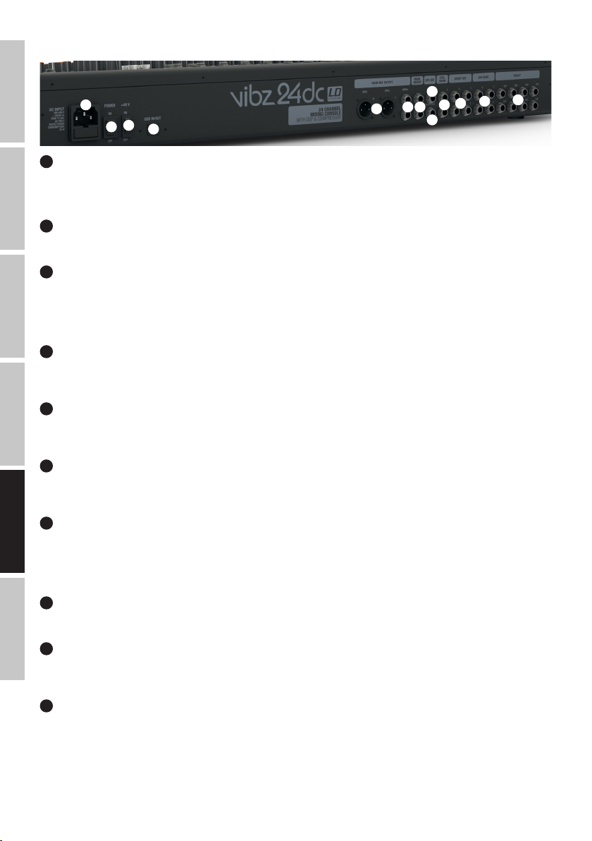
PRZYŁĄCZA, ELEMENTY OBSŁUGI I WSKAŹNIKI
ENGLISH
Gniazdo sieciowe IEC ze zintegrowaną podstawą bezpiecznika. W zestawie znajduje się odpowiedni kabel sieciowy.
WAŻNA INFORMACJA: bezpiecznik należy wymieniać wyłącznie na bezpiecznik tego samego typu i o takich samych parametrach, zgodnie z
nadrukiem na urządzeniu. Jeżeli bezpiecznik stale się przepala, należy skontaktować się z autoryzowanym centrum serwisowym.
DEUTSCHFRANCAIS
Włącznik/Wyłącznik dopływu zasilania do urządzenia (ON = włączony).
Zasilanie phantom (+48 V) umożliwiające pracę z mikrofonami pojemnościowymi nieposiadającymi własnego zasilania. Przestawić przełącznik w
pozycję ON (przycisk wciśnięty, dioda sygnalizacyjna świeci – nr 85), aby włączyć zasilanie phantom dla wejść mikrofonowych XLR, lub w pozycję
OFF, aby je wyłączyć (przycisk niewciśnięty, czerwona dioda sygnalizacyjna nie świeci). Zasilanie phantom należy włączyć/wyłączyć po/przed
podłączaniu/odłączeniem mikrofonu. Ponadto przed włączeniem regulatory poziomów kanałów mikrofonowych należy ustawić na minimum.
Gniazdo USB typu B służące do połączenia z komputerem z zainstalowanym systemem Windows lub MAC (Windows XP–Windows 10, MAC OS X,
USB 2.0, nagrywanie i playback).
Symetryczne stereofoniczne wyjście liniowe wyposażone w 3-stykowe gniazda XLR do podłączenia aktywnego systemu nagłośnienia.
ESPAÑOL
Wyprowadzenie sumy sygnałów pulpitu mikserskiego.
Niesymetryczne stereofoniczne wyjście liniowe wyposażone w gniazda jack 6,3 mm do podłączenia aktywnego systemu nagłośnienia.
Wyprowadzenie sumy sygnałów pulpitu mikserskiego.
1
3
2
1
GNIAZDO SIECIOWE I UCHWYT BEZPIECZNIKOWY
2
POWER ON/OFF
3
+48 V ON/OFF
4
USB IN/OUT
5
MAIN MIX OUTPUT (BAL)
6
MAIN MIX OUTPUT (UNBAL)
4
5
8
6 7
9
12
11
10
13
7
MAIN INSERT
Dwa 3-stykowe gniazda jack 6,3 mm do włączania zewnętrznego urządzenia przetwarzającego sygnał (kompresora, bramki szumów, korektora
dźwięku itd.) na sumę kanałów stereo. Do podłączenia wymagany jest specjalny kabel Insert (kabel Y, zakończony jednym wtykiem jack stereo i
dwoma wtykami jack mono lub XLR). Przyporządkowanie styków gniazda jest następujące: TIP (nasadka) = Send (wysyłka sygnału), RING
(pierścień) = Return (powrót sygnału), SLEEVE (tuleja) = masa (uziemienie).
8
DFX OUT
3-stykowe gniazda jack 6,3 mm do emitowania sygnału efektu.
9
ITALIANO POLSKI
FOOT SW (DFX MUTE)
Gniazdo jack 6,3 mm do podłączenia przełącznika nożnego (zestyku zwiernego) służącego do zdalnego włączania/wyłączania funkcji wyciszenia
wewnętrznego efektu (przełącznik nożny opcjonalny).
10
CTRL ROOM
Niesymetryczne wyjścia liniowe wyposażone w gniazda jack 6,3 mm do podłączenia aktywnych monitorów itd. Emitowanie sumy kanałów lub
sygnałów grupowych 1–2 lub 3–4 z pulpitu mikserskiego lub sygnału PFL (przełączany).
76
Page 77
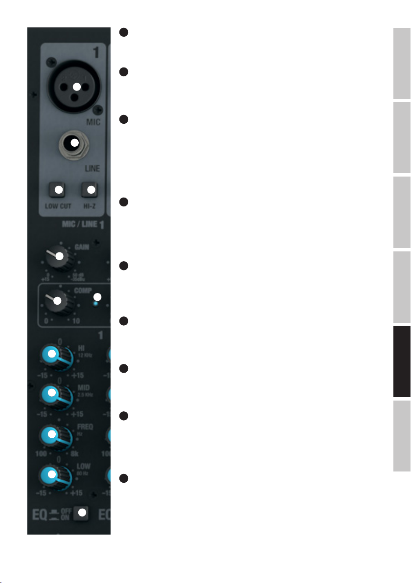
11
GROUP OUT 1–4
Niesymetryczne wyjścia liniowe wyposażone w gniazda jack 6,3 mm do podłączenia aktywnych systemów
nagłośniających itd. Emitowanie grupy sygnałów od 1 do 4 z pulpitu mikserskiego.
12
AUX SEND 1–4
14
15
Niesymetryczne monofoniczne wyjścia liniowe wyposażone w gniazda jack 6,3 mm do sterowania
zewnętrznymi efektami w trybie (POST Fader) lub wyprowadzenia sygnału do aktywnych monitorów
scenicznych w trybie (PRE Fader).
13
INSERT CH1–CH8
3-stykowe gniazda jack 6,3 mm do włączania zewnętrznego urządzenia przetwarzającego sygnał (kompresora, bramki szumów) do odpowiedniego kanału od 1 do 8. Do podłączenia wymagany jest specjalny kabel
Insert (kabel Y, zakończony jednym wtykiem jack stereo i dwoma wtykami jack mono lub XLR).
Przyporządkowanie styków gniazda jest następujące: TIP (nasadka) = Send (wysyłka sygnału), RING
(pierścień) = Return (powrót sygnału), SLEEVE (tuleja) = masa (uziemienie).
16 17
18
19
21
22
23
24
KANAŁY MONO 1–16
14
MIC KANAL 1–16
Symetryczne wejścia kanałów 1–16 wyposażone w 3-stykowe gniazda XLR do podłączenia mikrofonów. Aby
umożliwić pracę z mikrofonami pojemnościowymi, urządzenie zostało wyposażone w 48 V zasilanie phantom,
które po włączeniu jest dostępne bezpośrednio z gniazd XLR (nr 3). Przed podłączeniem/odłączeniem mikrofonów należy ustawić regulator wzmocnienia (nr 18) na minimum (maksymalny obrót w lewo), a zasilanie
phantom włączyć/wyłączyć po/przed podłączeniu/odłączeniem mikrofonu.
LINE IN KANAL 1–16
15
Symetryczne wejścia kanałów mono od 1 do 16 wyposażone w gniazda jack 6,3 mm do podłączenia
zewnętrznych urządzeń wejściowych o liniowym poziomie sygnału. Przed podłączeniem/odłączeniem kabla
zakończonego złączem jack 6,3 mm należy ustawić regulator wzmocnienia (nr 18) na minimum
20
(maksymalny obrót w lewo).
LOW CUT KANAL 1–16
16
Odcięcie tonów niskich w celu stłumienia dolnej części pasma. Głównie w przypadku transmisji głosu i wokalu włączony filtr dolnozaporowy (przycisk LOW CUT wciśnięty) może zmniejszyć ilość zakłócających tonów
niskich, poprawiając w ten sposób zrozumiałość tekstu. Częstotliwość graniczna to 95 Hz.
HI-Z KANAL 1–4
17
Za pomocą tego przycisku wejścia jack kanałów od 1 do 4 mogą zostać oddzielnie włączone (w celu aktywowania wcisnąć przycisk). Dzięki temu możliwe jest użycie kanałów pod instrumenty, np. gitary akustyczne
lub basowe.
GAIN KANAL 1–16
18
Regulowanie wstępnego wzmocnienia wejścia mikrofonowego w zakresie od 0 do 50 dB lub czułości
wejścia liniowego w zakresie od +15 do -35 dBu. Ustawić regulator wzmocnienia tak, aby dioda Clip-LED
odpowiedniego kanału zapalała się na krótko wyłącznie dla szczytowych poziomów przekazywanego sygnału.
Unikać ciągłego świecenia się diody Clip-LED poprzez obniżenie wstępnego wzmocnienia wejścia lub
czułości wejścia.
19
COMP KANAL 1–8
Bezstopniowo regulowany kompresor dla kanałów od 1 do 8. W zależności od ustawienia przekazywany
sygnał zostanie mniej lub bardziej skompresowany, tj. dynamika sygnału zostanie zmniejszona (maksymalny
25
obrót regulatora w lewo = kompresor wyłączony, maksymalny obrót w prawo = maksymalna kompresja).
Zmniejszanie się poziomu sygnału spowodowane zwiększaniem stopnia kompresji jest automatycznie
kompensowane przez urządzenie kompresujące (kompresor). Zastosowanie kompresora może okazać się
przydatne na przykład w celu uwydatnienia (wysunięcia na pierwszy plan) wokalu w miksie.
FRANCAISDEUTSCHENGLISH
ITALIANOPOLSKIESPAÑOL
77
Page 78
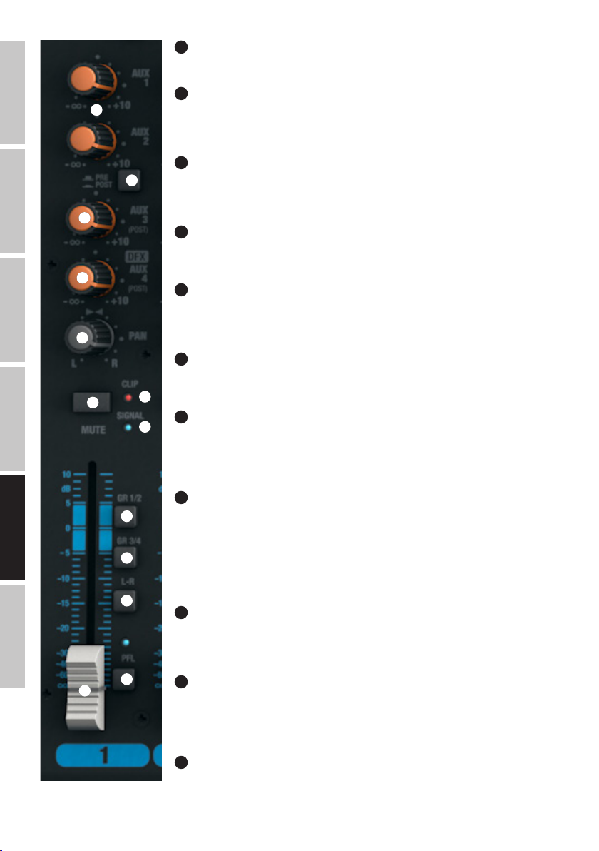
ENGLISH
DEUTSCHFRANCAIS
ESPAÑOL
20
COMP LED
Wskaźnik LED świeci się tak długo, jak aktywny jest kompresor.
21
EQUALIZER HI KANAL 1–16
26
27
28
29
30
31
Korektor dźwięku tonów wysokich kanałów od 1 do 16 (12 kHz, +/−15 dB). Obrót w lewo powoduje
zmniejszenie poziomu tonów wysokich, a obrót w prawo jego zwiększenie. W pozycji środkowej (kliknięcie)
korektor jest nieaktywny.
22
EQUALIZER MID KANAL 1–16
Korektor dźwięku tonów średnich kanałów od 1 do 16 (ustawiana częstotliwość +/−15 dB). Obrót w lewo
powoduje zmniejszenie poziomu tonów średnich, a obrót w prawo jego zwiększenie. W pozycji środkowej
(kliknięcie) korektor jest nieaktywny.
23
EQUALIZER MID FREQ KANAL 1–16
Częstotliwość tonów średnich. Ustawić częstotliwość, która ma być zwiększona lub zmniejszona za pomocą
tego regulatora od 200 Hz do 8 kHz.
24
EQUALIZER LOW KANAL 1–16
Korektor dźwięku tonów niskich kanałów od 1 do 16 (80 Hz, +/−15 dB). Obrót w lewo powoduje zmniejszenie
poziomu tonów niskich, a obrót w prawo jego zwiększenie. W pozycji środkowej (kliknięcie) korektor jest
nieaktywny.
25
EQ ON /OFF KANAL 1–16
Przycisk do włączania i wyłączania korektora dźwięku (HI, MID oraz LOW). Korektor dźwięku jest włączony we
wciśniętej pozycji i wyłączony w niewciśniętej pozycji.
34
26
33
AUX 1 + AUX 2 KANAL 1–16
Regulatory poziomów sygnałów służące do dodawania sygnałów kanałów od 1 do 16 na zewnętrzne efekty
(wysyłka do efektu, przycisk nr 27 – POST) lub wyprowadzenia sygnału do monitorów scenicznych (wysyłka
do monitora, przycisk nr 27 – PRE). Skorzystać z wyjść liniowych AUX SEND 1 i 2 (nr 12) w celu wyprowadzenia sygnału.
ITALIANO POLSKI
78
27
AUX 1 + AUX 2 PRE/POST KANAL 1–16
35
36
37
38
32
Jeżeli sygnał wyprowadzany jest do zewnętrznego efektu za pomocą wyjścia AUX 1 lub AUX 2, należy
upewnić się, że przycisk znajduje się we wciśniętej pozycji POST. Wyprowadzany w ten sposób sygnał będzie
przechodził teraz przez regulator poziomu kanału (nr 32), w związku z czym jego poziom będzie zależny od
ustawienia regulatora. W celu wyprowadzenia sygnału do monitorów scenicznych należy upewnić się, że
przycisk znajduje się w niewciśniętej pozycji PRE. Wyprowadzany w ten sposób sygnał nie będzie przechodził
teraz przez regulator poziomu kanału (nr 32), w związku z czym głośność monitora scenicznego może zostać
ustawiona niezależnie od głośności kanału.
28
AUX 3 POST KANAL 1–16
Regulator poziomu sygnału służący do dodawania sygnału kanałów od 1 do 16 na zewnętrzne efekty (wysyłka do efektu w trybie post fader). Skorzystać z wyjścia liniowego AUX SEND 3 (nr 12) w celu wyprowadzenia
sygnału.
29
LEVEL DFX/AUX 4 POST KANAL 1–16
Regulatory poziomów sygnałów służące do dodawania sygnałów kanałów od 1 do 16 na wewnętrzny cyfrowy
efekt (wysyłka do efektu w trybie post fader). Skorzystać z wyjścia liniowego AUX SEND 4 (nr 12) w celu
sterowania zewnętrznym efektem. W przypadku wykorzystania gniazda jack AUX SEND 4 nastąpi
automatyczne pominięcie wewnętrznego efektu, w związku z czym nie będzie można z niego korzystać.
30
PAN KANAL 1–16
Za pomocą regulatora panoramy można ustawić pozycję sygnału odpowiedniego kanału w polu stereo
sygnału całkowitego (ustawienie centralne oznacza odbiór sygnału w centrum pola stereo).
Page 79

31
MUTE KANAL 1–16
W celu wyciszenia danego kanału należy upewnić się, że przycisk wyciszania MUTE odpowiedniego kanału znajduje się we wciśniętej pozycji. Po
naciśnięciu przycisku wyciszania MUTE zapali się znajdująca się obok niego dioda. Po ponownym naciśnięciu dioda zgaśnie, sygnalizując
dezaktywowanie wyciszenia.
32
FADER KANAL 1–16
Regulatory poziomów kanałów od 1 do 16. Przestawić suwak tłumika nastawnego w górę, aby zwiększyć głośność danego kanału, lub w dół, aby
ją zmniejszyć.
33
SIGNAL-LED KANAL 1–16
Dioda LED sygnału świeci, jak długo dochodzi sygnał audio do odpowiedniego kanału (w zależności od wejściowego poziomu i ustawienia
wstępnego wzmocnienia lub czułości wejścia – GAIN).
34
CLIP-LED KANAL 1–16
Gdy zapali się czerwona dioda Clip-LED, oznacza to, że wejście danego kanału pracuje na granicy zniekształceń. Ustawić regulator wzmocnienia
(GAIN, nr 18) tak, aby dioda Clip-LED zapalała się na krótko wyłącznie dla szczytowych poziomów przekazywanego sygnału. Unikać ciągłego
świecenia się diody Clip-LED poprzez obniżenie wstępnego wzmocnienia wejścia lub czułości wejścia, ew. zmniejszyć głośność podłączonego
urządzenia.
35
GR 1/2 KANAL 1–16
W celu przypisania danego kanału do grupy kanałów 1 (regulatory PAN/BAL obrócone maksymalnie w lewo), grupy kanałów 2 (regulator PAN
obrócony maksymalnie w prawo) lub równomiernego przydzielenia sygnału do obu grup kanałów 1 i 2 (regulator PAN w ustawieniu centralnym)
należy nacisnąć przycisk GR 1/2 (pozycja wciśnięta). Naciśnięcie przycisku spowoduje przetrasowanie sygnałów kanałów przypisanych do jednej
grupy na odpowiednie wyjścia liniowe GROUP OUT 1/2. Głośność całkowitą utworzonej w ten sposób grupy można regulować za pomocą regulatora
głośności GROUP 1/2 (nr 104). Jeżeli sygnały audio mają być przetrasowywane na sumę kanałów MAIN MIX, należy nacisnąć przycisk L-R (nr 105)
– pozycja wciśnięta.
36
GR 3/4 KANAL 1–16
W celu przypisania danego kanału do grupy kanałów 3 (regulatory PAN/BAL obrócone maksymalnie w lewo), grupy kanałów 4 (regulator PAN
obrócony maksymalnie w prawo) lub równomiernego przydzielenia sygnału do obu grup kanałów 3 i 4 (regulator PAN w ustawieniu centralnym)
należy nacisnąć przycisk GR 3/4 (pozycja wciśnięta). Naciśnięcie przycisku spowoduje przetrasowanie sygnałów kanałów przypisanych do jednej
grupy na odpowiednie wyjścia liniowe GROUP OUT 3/4. Głośność całkowitą utworzonej w ten sposób grupy można regulować za pomocą regulatora
głośności GROUP 3/4 (nr 106). Jeżeli sygnały audio mają być przetrasowywane na sumę kanałów MAIN MIX, należy nacisnąć przycisk L-R (nr 107)
– pozycja wciśnięta.
FRANCAISDEUTSCHENGLISH
37
L-R KANAL 1–16
W celu przetrasowania kanału wejściowego (kanał 1–16) bezpośrednio na sumę kanałów MAIN MIX należy nacisnąć przycisk L–R odpowiedniego
kanału (pozycja wciśnięta).
38
PFL KANAL 1–16
W celu, po pierwsze, przeprowadzenia niezależnego od ustawienia regulatora poziomu kanału (nr 32) – odsłuchu kontrolnego sygnału danego
kanału za pomocą słuchawek podłączonych do wyjścia słuchawkowego PHONES (nr 82), po drugie, dokładniejszego ustawienia wzmocnienia
(Gain), gdyż sygnał wejściowy jest wskazywany na 12-segmentowym wskaźniku LED sumy kanałów MAIN MIX, należy upewnić się, że przycisk PFL
(Pre Fader Listen) znajduje się we wciśniętej pozycji. Jednocześnie zapalają się dioda LED PFL odpowiedniego kanału i dioda LED PFL w ramach
wskaźnika poziomu sumy kanałów MAIN MIX. Po ponownym naciśnięciu przycisku PFL (pozycja wyjściowa) diody LED PFL zgasną.
ITALIANOPOLSKIESPAÑOL
79
Page 80
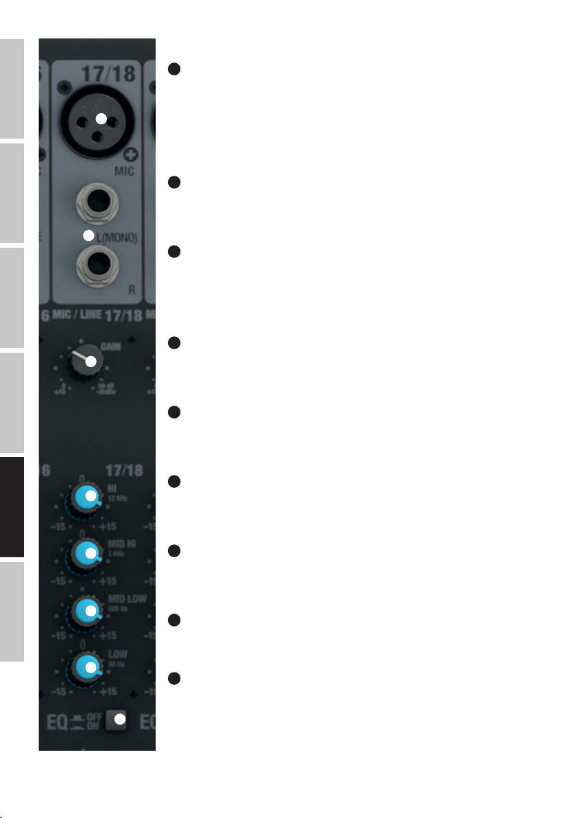
ENGLISH
DEUTSCHFRANCAIS
ESPAÑOL
KANAŁY STEREO 17/18 I 19/20
39
MIC KANAL 17/18 & 19/20
Symetryczne wejścia kanałów 17/18 i 19/20 wyposażone w 3-stykowe gniazda XLR do podłączenia
mikrofonów. Kanały 17/18 i 19/20 mogą pełnić funkcję zarówno kanałów mono, jak i stereo, w zależności
od podłączonych urządzeń (XLR i gniazdo jack L IN = mono/gniazdo jack L i R IN = stereo). Aby umożliwić
39
40
41
pracę z mikrofonami pojemnościowymi, urządzenie zostało wyposażone w 48 V zasilanie phantom, które po
włączeniu jest dostępne bezpośrednio z gniazd XLR (nr 3). Przed podłączeniem/odłączeniem mikrofonów
należy ustawić regulator wzmocnienia (nr 41) na minimum (maksymalny obrót w lewo), a zasilanie phantom
włączyć/wyłączyć po/przed podłączeniu/odłączeniem mikrofonu.
40
LINE IN L/R KANAL 17/18 & 19/20
Niesymetryczne wejścia kanałów stereo 17/18 oraz 19/20 wyposażone w gniazda jack 6,3 mm do
podłączenia zewnętrznych urządzeń wejściowych o liniowym poziomie sygnału (np. keyboardu). W przypadku
wykorzystania tylko lewego (L) gniazda wejściowego kanał będzie pracował w trybie mono.
41
GAIN KANAL 17/18 & 19/20
Regulowanie wstępnego wzmocnienia wejścia mikrofonowego w zakresie od 0 do 50 dB lub czułości wejścia
liniowego w zakresie od +15 do -35 dBu. Ustawić regulator wzmocnienia tak, aby dioda Clip-LED
odpowiedniego kanału zapalała się na krótko wyłącznie dla szczytowych poziomów przekazywanego sygnału.
Unikać ciągłego świecenia się diody Clip-LED poprzez obniżenie wstępnego wzmocnienia wejścia lub
czułości wejścia, ew. zmniejszyć głośność podłączonego urządzenia.
42
EQUALIZER HI KANAL 17/18 & 19/20
Korektor dźwięku tonów wysokich kanałów 17/18 oraz 19/20 (12 kHz, +/−15 dB). Obrót w lewo powoduje
zmniejszenie poziomu tonów wysokich, a obrót w prawo jego zwiększenie. W pozycji środkowej (kliknięcie)
korektor jest nieaktywny.
43
EQUALIZER MID HI KANAL 17/18 & 19/20
Korektor dźwięku tonów średnich kanałów 17/18 oraz 19/20 (3 kHz, +/−15 dB). Obrót w lewo powoduje
zmniejszenie poziomu tonów średnich, a obrót w prawo jego zwiększenie. W pozycji środkowej (kliknięcie)
korektor jest nieaktywny.
ITALIANO POLSKI
80
44
42
43
44
45
46
EQUALIZER MID LOW KANAL 17/18 & 19/20
Korektor dźwięku tonów niskich kanałów 17/18 oraz 19/20 (500Hz, +/−15 dB). Obrót w lewo powoduje
zmniejszenie poziomu tonów niskich, a obrót w prawo jego zwiększenie. W pozycji środkowej (kliknięcie)
korektor jest nieaktywny.
45
EQUALIZER LOW KANAL 17/18 & 19/20
Korektor dźwięku basów kanałów 17/18 oraz 19/20 (80 Hz, +/−15 dB). Obrót w lewo powoduje zmniejszenie
poziomu tonów niskich, a obrót w prawo jego zwiększenie. W pozycji środkowej (kliknięcie) korektor jest
nieaktywny.
46
EQ ON/OFF KANAL 17/18 & 19/20
Przycisk do włączania i wyłączania korektora dźwięku (HI, MID HI, MID LOW oraz LOW). Korektor dźwięku jest
włączony we wciśniętej pozycji i wyłączony w niewciśniętej pozycji.
47
AUX 1 + AUX 2 KANAL 17/18 & 19/20
Regulatory poziomów sygnałów służące do dodawania sygnałów kanałów 17/18 i 19/20 na zewnętrzne
efekty (wysyłka do efektu, przycisk nr 48 – POST) lub wyprowadzenia sygnału do monitorów scenicznych
(wysyłka do monitora, przycisk nr 48 – PRE). Skorzystać z wyjść liniowych AUX SEND 1 i 2 (nr 12) w celu
wyprowadzenia sygnału.
Page 81
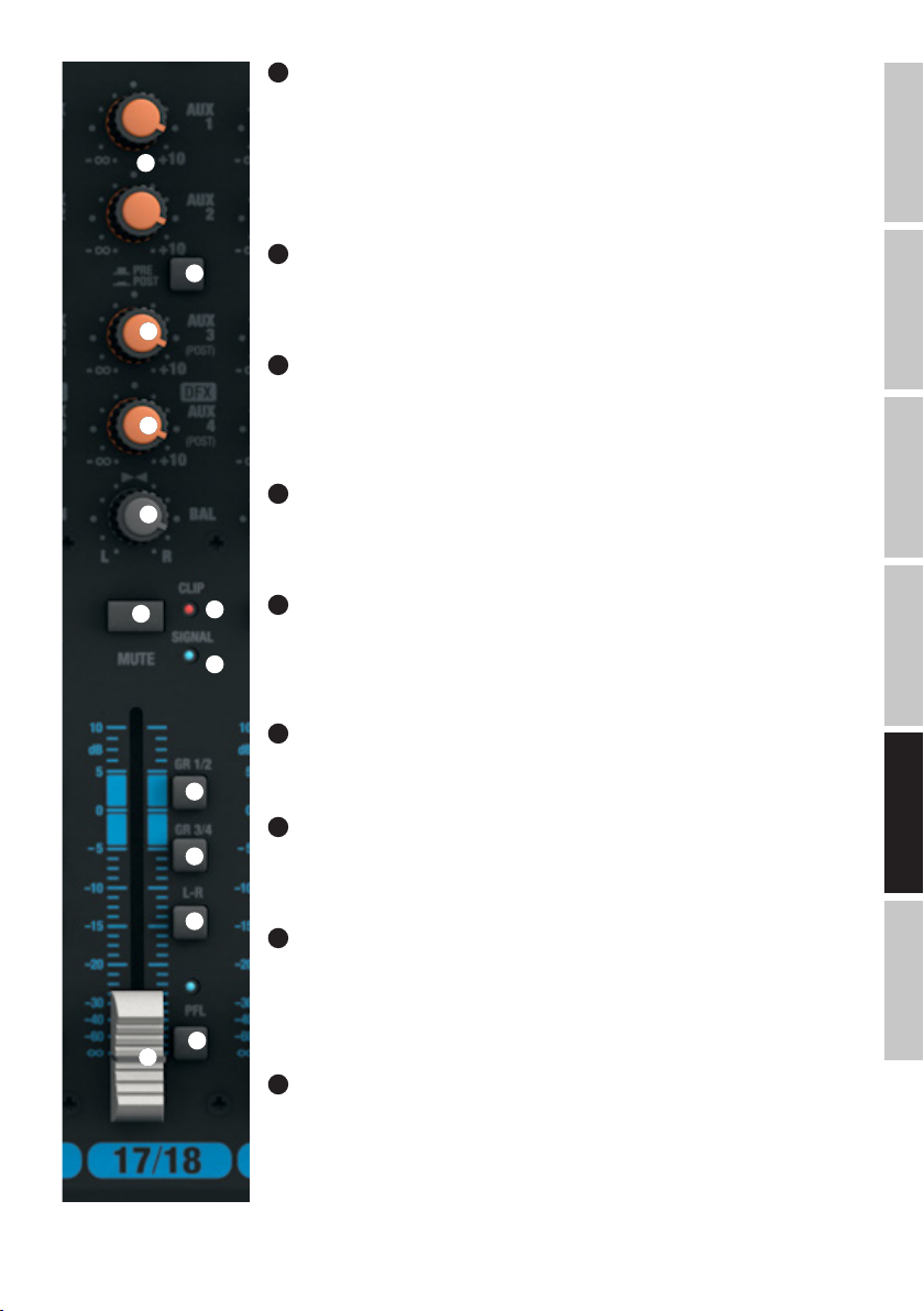
48
AUX 1 + AUX 2 PRE/POST KANAL 17/18 & 19/20
Jeżeli sygnał wyprowadzany jest do zewnętrznego efektu za pomocą wyjścia AUX 1 lub AUX 2, należy
upewnić się, że przycisk znajduje się we wciśniętej pozycji POST. Wyprowadzany w ten sposób sygnał będzie
przechodził teraz przez regulator poziomu kanału (nr 53), w związku z czym jego poziom będzie zależny od
47
48
49
50
51
52
ustawienia regulatora. W celu wyprowadzenia sygnału do monitorów scenicznych należy upewnić się, że
przycisk znajduje się w niewciśniętej pozycji PRE. Wyprowadzany w ten sposób sygnał nie będzie przechodził
teraz przez regulator poziomu kanału (nr 53), w związku z czym głośność monitora scenicznego może zostać
ustawiona niezależnie od głośności kanału.
49
AUX 3 POST KANAL 17/18 & 19/20
Regulator poziomu sygnału służący do dodawania sygnału kanałów 17/18 i 19/20 na zewnętrzne efekty
(wysyłka do efektu w trybie post fader). Skorzystać z wyjścia liniowego AUX SEND 3 (nr 12) w celu wyprowadzenia sygnału.
50
LEVEL DFX / AUX 4 POST KANAL 17/18 & 19/20
Regulatory poziomów sygnałów służące do dodawania sygnałów kanałów 17/18 i 19/20 na wewnętrzny
cyfrowy efekt (wysyłka do efektu w trybie post fader). Skorzystać z wyjścia liniowego AUX SEND 4 (nr 12)
w celu sterowania zewnętrznym efektem. W przypadku wykorzystania gniazda jack AUX SEND 4 nastąpi
automatyczne pominięcie wewnętrznego efektu, w związku z czym nie będzie można z niego korzystać.
51
BAL KANAL 17/18 & 19/20
Za pomocą regulatora balansu można ustawić stosunek głośności między lewym a prawym kanałem przekazywanego sygnału stereo. Po podłączeniu wtyczki XLR lub wtyku jack tylko do lewego gniazda L (MONO)
wejścia liniowego kanałów 17/18 i 19/20 regulator będzie pełnił funkcję regulatora panoramy.
52
55
54
MUTE KANAL 17/18 & 19/20
W celu wyciszenia danego kanału należy upewnić się, że przycisk wyciszania MUTE odpowiedniego kanału
znajduje się we wciśniętej pozycji. Po naciśnięciu przycisku wyciszania MUTE zapali się znajdująca się obok
niego dioda. Po ponownym naciśnięciu dioda zgaśnie, sygnalizując
dezaktywowanie wyciszenia.
FRANCAISDEUTSCHENGLISH
53
FADER KANAL 17/18 & 19/20
Regulator poziomu kanałów 17/18 oraz 19/20. Przestawić suwak tłumika nastawnego w górę, aby zwiększyć
56
57
58
59
53
głośność danego kanału lub w dół, aby ją zmniejszyć.
54
SIGNAL-LED KANAL 17/18 & 19/20
Dioda LED sygnału świeci, jak długo dochodzi sygnał audio do odpowiedniego kanału (w zależności od
wejściowego poziomu i ustawienia
wstępnego wzmocnienia lub czułości wejścia – GAIN).
55
CLIP-LED KANAL 17/18 & 19/20
Gdy zapali się czerwona dioda Clip-LED, oznacza to, że wejście danego kanału pracuje na granicy zniekształceń. Ustawić regulator wzmocnienia (GAIN, nr 41) tak, aby dioda Clip-LED zapalała się na krótko wyłącznie
dla szczytowych poziomów przekazywanego sygnału. Unikać ciągłego świecenia się diody Clip-LED poprzez
obniżenie wstępnego wzmocnienia wejścia lub czułości wejścia, ew. zmniejszyć głośność podłączonego
urządzenia.
56
GR 1/2 KANAL 17/18 & 19/20
W celu przypisania danego kanału do grupy kanałów 1 (regulatory BAL obrócone maksymalnie w lewo), grupy
kanałów 2 (regulator BAL obrócony maksymalnie w prawo) lub równomiernego przydzielenia sygnału do
obu grup kanałów 1 i 2 (regulator BAL w ustawieniu centralnym) należy nacisnąć przycisk GR 1/2 (pozycja
wciśnięta). Naciśnięcie przycisku spowoduje przetrasowanie sygnałów kanałów przypisanych do jednej grupy
na odpowiednie wyjścia liniowe GROUP OUT 1/2. Głośność całkowitą utworzonej w ten sposób grupy można
regulować za pomocą regulatora głośności GROUP 1/2 (nr 104). Jeżeli sygnały audio mają być przetrasowywane na sumę kanałów MAIN MIX, należy nacisnąć przycisk L-R (nr 105) – pozycja wciśnięta.
ITALIANOPOLSKIESPAÑOL
81
Page 82
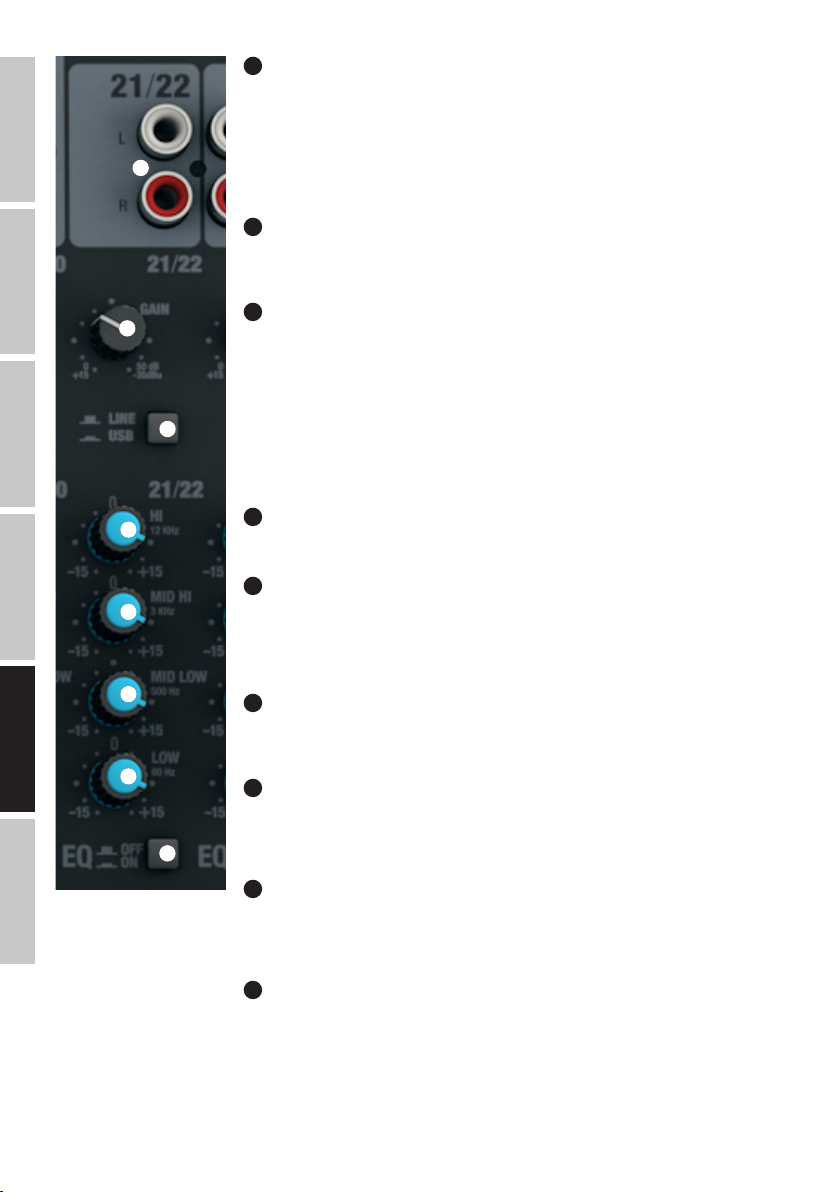
ENGLISH
57
GR 3/4 KANAL 17/18 & 19/20
W celu przypisania danego kanału do grupy kanałów 3 (regulatory BAL obrócone maksymalnie w lewo), grupy
kanałów 4 (regulator BAL obrócony maksymalnie w prawo) lub równomiernego przydzielenia sygnału do
obu grup kanałów 3 i 4 (regulator BAL w ustawieniu centralnym) należy nacisnąć przycisk GR 3/4 (pozycja
wciśnięta). Naciśnięcie przycisku spowoduje przetrasowanie sygnałów kanałów przypisanych do jednej grupy
60
na odpowiednie wyjścia liniowe GROUP OUT 3/4. Głośność całkowitą utworzonej w ten sposób grupy można
regulować za pomocą regulatora głośności GROUP 3/4 (nr 106). Jeżeli sygnały audio mają być przetrasowywane na sumę kanałów MAIN MIX, należy nacisnąć przycisk L-R (nr 107) – pozycja wciśnięta.
58
L-R KANAL 17/18 & 19/20
W celu przetrasowania kanału wejściowego (kanał 17/18 i 19/20) bezpośrednio na sumę kanałów MAIN MIX
należy nacisnąć przycisk L–R odpowiedniego kanału (pozycja wciśnięta).
DEUTSCHFRANCAIS
ESPAÑOL
ITALIANO POLSKI
59
61
62
PFL KANAL 17/18 & 19/20
W celu, po pierwsze, przeprowadzenia niezależnego od ustawienia regulatora poziomu kanału (nr 53) – odsłuchu kontrolnego sygnału danego kanału za pomocą słuchawek podłączonych do wyjścia słuchawkowego
PHONES (nr 82), po drugie, dokładniejszego ustawienia wzmocnienia (Gain), gdyż sygnał wejściowy jest
wskazywany na 12-segmentowym wskaźniku LED sumy kanałów MAIN MIX, należy upewnić się, że przycisk
PFL (Pre Fader Listen) znajduje się we wciśniętej pozycji. Jednocześnie zapalają się dioda LED PFL odpowiedniego kanału i dioda LED PFL w ramach wskaźnika poziomu sumy kanałów MAIN MIX. Po ponownym
naciśnięciu przycisku PFL (pozycja wyjściowa) diody LED PFL zgasną.
KANAŁY STEREO 21/22 I 23/24
60
63
64
65
66
67
LINE IN L/R KANAL 21/22 & 23/24
Niesymetryczne wejścia liniowe z gniazdami cinch L i R.
61
GAIN KANAL 21/22 & 23/24
Regulowanie czułości wejścia liniowego od +15 do -35 dBu. Ustawić regulator wzmocnienia tak, aby dioda
Clip-LED odpowiedniego kanału zapalała się na krótko wyłącznie dla szczytowych poziomów przekazywanego sygnału. Unikać ciągłego świecenia się diody Clip-LED poprzez obniżenie czułości wejścia, ew. zmniejszyć
głośność podłączonego urządzenia.
62
LINE/USB 21/22
Przełączenie źródła sygnału na kanał stereo 21/22. Gniazda cinch są aktywne jako źródło sygnału w niewciśniętej pozycji, a w pozycji wciśniętej jest nim interfejs USB na tylnej ścianie pulpitu mikserskiego.
63
EQUALIZER HI KANAL 21/22 & 23/24
Korektor dźwięku tonów wysokich kanałów 21/22 oraz 23/24 (12 kHz, +/−15 dB). Obrót w lewo powoduje
zmniejszenie poziomu tonów wysokich, a obrót w prawo jego zwiększenie. W pozycji środkowej (kliknięcie)
korektor jest nieaktywny.
64
EQUALIZER MID HI KANAL 21/22 & 23/24
Korektor dźwięku tonów średnich kanałów 21/22 oraz 23/24 (3 kHz, +/−15 dB). Obrót w lewo powoduje
zmniejszenie poziomu tonów średnich, a obrót w prawo jego zwiększenie. W pozycji środkowej (kliknięcie)
korektor jest nieaktywny.
82
65
EQUALIZER MID LOW KANAL 21/22 & 23/24
Korektor dźwięku tonów niskich kanałów 21/22 oraz 23/24 (500 Hz, +/−15 dB). Obrót w lewo powoduje
zmniejszenie poziomu tonów niskich, a obrót w prawo jego zwiększenie. W pozycji środkowej (kliknięcie)
korektor jest nieaktywny.
Page 83

66
EQUALIZER LOW KANAL 21/22 & 23/24
Korektor dźwięku basów kanałów 21/22 oraz 23/24 (80 Hz, +/−15 dB). Obrót w lewo powoduje zmniejszenie
poziomu tonów niskich, a obrót w prawo jego zwiększenie. W pozycji środkowej (kliknięcie) korektor jest
nieaktywny.
68
67
EQ ON/OFF KANAL 21/22 & 23/24
Przycisk do włączania i wyłączania korektora dźwięku (HI, MID HI, MID LOW oraz LOW). Korektor dźwięku jest
włączony we wciśniętej pozycji i wyłączony w niewciśniętej pozycji.
69
70
71
72
73
77
68
AUX 1 + AUX 2 KANAL 21/22 & 23/24
Regulatory poziomów sygnałów służące do dodawania sygnałów kanałów 21/22 i 23/24 na zewnętrzne
efekty (wysyłka do efektu, przycisk nr 69 – POST) lub wyprowadzenia sygnału do monitorów scenicznych
(wysyłka do monitora, przycisk nr 69 – PRE). Skorzystać z wyjść liniowych AUX SEND 1 i 2 (nr 12) w celu
wyprowadzenia sygnału.
69
AUX 1 + AUX 2 PRE/POST KANAL 21/22 & 23/24
Jeżeli sygnał wyprowadzany jest do zewnętrznego efektu za pomocą wyjścia AUX 1 lub AUX 2, należy
upewnić się, że przycisk znajduje się we wciśniętej pozycji POST. Wyprowadzany w ten sposób sygnał będzie
przechodził teraz przez regulator poziomu kanału (nr 74), w związku z czym jego poziom będzie zależny od
ustawienia regulatora. W celu wyprowadzenia sygnału do monitorów scenicznych należy upewnić się, że
przycisk znajduje się w niewciśniętej pozycji PRE. Wyprowadzany w ten sposób sygnał nie będzie przechodził
teraz przez regulator poziomu kanału (nr 74), w związku z czym głośność monitora scenicznego może zostać
ustawiona niezależnie od głośności kanału.
70
76
75
AUX 3 POST KANAL 21/22 & 23/24
Regulator poziomu sygnału służący do dodawania sygnału kanałów 21/22 i 23/24 na zewnętrzne efekty
(wysyłka do efektu w trybie post fader). Skorzystać z wyjścia liniowego AUX SEND 3 (nr 12) w celu wyprowadzenia sygnału.
71
LEVEL DFX/AUX 4 POST KANAL 21/22 & 23/24
Regulatory poziomów sygnałów służące do dodawania sygnałów kanałów 21/22 i 23/24 na wewnętrzny
cyfrowy efekt (wysyłka do efektu w trybie post fader). Skorzystać z wyjścia liniowego AUX SEND 4 (nr 12)
w celu sterowania zewnętrznym efektem. W przypadku wykorzystania gniazda jack AUX SEND 4 nastąpi
automatyczne pominięcie wewnętrznego efektu, w związku z czym nie będzie można z niego korzystać.
FRANCAISDEUTSCHENGLISH
72
78
79
80
74
BAL KANAL 21/22 & 23/24
Za pomocą regulatora balansu można ustawić stosunek głośności między lewym a prawym kanałem
przekazywanego sygnału stereo.
73
MUTE KANAL 21/22 & 23/24
W celu wyciszenia danego kanału należy upewnić się, że przycisk wyciszania MUTE odpowiedniego kanału
znajduje się we wciśniętej pozycji. Po naciśnięciu przycisku wyciszania MUTE zapali się znajdująca się obok
niego dioda. Po ponownym naciśnięciu dioda zgaśnie, sygnalizując
dezaktywowanie wyciszenia.
74
FADER KANAL 21/22 & 23/24
Regulator poziomu kanałów 21/22 oraz 23/24. Przestawić suwak tłumika nastawnego w górę, aby zwiększyć
głośność danego kanału lub w dół, aby ją zmniejszyć.
75
SIGNAL-LED KANAL 21/22 & 23/24
Dioda LED sygnału świeci, jak długo dochodzi sygnał audio do odpowiedniego kanału (w zależności od
wejściowego poziomu i ustawienia
wstępnego wzmocnienia lub czułości wejścia – GAIN).
ITALIANOPOLSKIESPAÑOL
83
Page 84

76
CLIP-LED KANAL 21/22 & 23/24
Gdy zapali się czerwona dioda Clip-LED, oznacza to, że wejście danego kanału pracuje na granicy zniekształceń. Ustawić regulator wzmocnienia
(GAIN, nr 61) tak, aby dioda Clip-LED zapalała się na krótko wyłącznie dla szczytowych poziomów przekazywanego sygnału. Unikać ciągłego
świecenia się diody Clip-LED poprzez obniżenie wstępnego wzmocnienia wejścia lub czułości wejścia, ew. zmniejszyć głośność podłączonego
urządzenia.
ENGLISH
77
GR 1/2 KANAL 21/22 & 23/24
W celu przypisania danego kanału do grupy kanałów 1 (regulatory BAL obrócone maksymalnie w lewo), grupy kanałów 2 (regulator BAL obrócony
maksymalnie w prawo) lub równomiernego przydzielenia sygnału do obu grup kanałów 1 i 2 (regulator BAL w ustawieniu centralnym) należy
nacisnąć przycisk GR 1/2 (pozycja wciśnięta). Naciśnięcie przycisku spowoduje przetrasowanie sygnałów kanałów przypisanych do jednej grupy
na odpowiednie wyjścia liniowe GROUP OUT 1/2. Głośność całkowitą utworzonej w ten sposób grupy można regulować za pomocą regulatora
głośności GROUP 1/2 (nr 104). Jeżeli sygnały audio mają być przetrasowywane na sumę kanałów MAIN MIX, należy nacisnąć przycisk L-R (nr 105)
– pozycja wciśnięta.
DEUTSCHFRANCAIS
GR 3/4 KANAL 21/22 & 23/24
78
W celu przypisania danego kanału do grupy kanałów 3 (regulatory BAL obrócone
maksymalnie w lewo), grupy kanałów 4 (regulator BAL obrócony maksymalnie w prawo) lub równomiernego przydzielenia sygnału do obu grup
kanałów 3 i 4 (regulator BAL w ustawieniu centralnym) należy nacisnąć przycisk GR 3/4 (pozycja wciśnięta). Naciśnięcie przycisku spowoduje
przetrasowanie sygnałów kanałów przypisanych do jednej grupy na odpowiednie wyjścia liniowe GROUP OUT 3/4. Głośność całkowitą utworzonej w
ten sposób grupy można regulować za pomocą regulatora głośności GROUP 3/4 (nr 106). Jeżeli sygnały audio mają być przetrasowywane na sumę
kanałów MAIN MIX, należy nacisnąć przycisk L-R (nr 107) – pozycja wciśnięta.
79
L-R KANAL 21/22 & 23/24
W celu przetrasowania kanału wejściowego (kanał 21/22 i 23/24) bezpośrednio na sumę kanałów MAIN MIX należy nacisnąć przycisk L–R odpowiedniego kanału (pozycja wciśnięta).
80
PFL KANAL 21/22 & 23/24
W celu, po pierwsze, przeprowadzenia niezależnego od ustawienia regulatora poziomu kanału (nr 74) – odsłuchu kontrolnego sygnału danego
kanału za pomocą słuchawek podłączonych do wyjścia słuchawkowego PHONES (nr 82), po drugie, dokładniejszego ustawienia wzmocnienia
ESPAÑOL
(Gain), gdyż sygnał wejściowy jest
wskazywany na 12-segmentowym wskaźniku LED sumy kanałów MAIN MIX
(zmniejszenie poziomu sygnału wejściowego przy zapalającej się diodzie CLIP-LED odpowiedniego regulatora GAIN), należy upewnić się, że przycisk
PFL (Pre Fader Listen) znajduje się we wciśniętej pozycji. Jednocześnie zapalają się dioda LED PFL odpowiedniego kanału i dioda LED PFL w
ramach wskaźnika poziomu sumy kanałów MAIN MIX. Po ponownym naciśnięciu przycisku PFL (pozycja wyjściowa) diody LED PFL zgasną.
SEKCJA MASTER
81
POWER LAMP
Gniazdo USB typu A do podłączenia lampy do pulpitu. Należy zwrócić uwagę, aby specyfikacja złącza pokrywała się ze specyfikacją lampy do
pulpitu (5 V DC, maks. 500 mA).
82
WYJŚCIE SŁUCHAWKOWE
Gniazdo jack 6,3 mm stereo do podłączenia słuchawek. To złącze służy do odsłuchu wybranych sygnałów:
A. Przycisk nr 100 (CTRL ROOM SOURCE MAIN/GR) niewciśnięty i brak wciśniętego przycisku PFL: suma sygnałów MAIN MIX.
ITALIANO POLSKI
B. Przycisk nr 100 wciśnięty i brak wciśniętego przycisku PFL: sygnał grupowy GROUP GR 1/2 lub GR 3/4 (zwrócić uwagę na przycisk nr 101 GR 1/2
/ GR 3/4).
C. Jeden lub kilka przycisków PFL kanałów wejściowych znajduje się we wciśniętej pozycji: Odpowiedni/odpowiednie kanał/kanały jest/są przechwytywany/e przed regulatorem poziomów sygnałów (Pre Fader Listening).
83
STEREO GRAPHIC EQ
Graficzny, 7-pasmowy korektor dźwięku sumy kanałów MAIN MIX.
84
Page 85
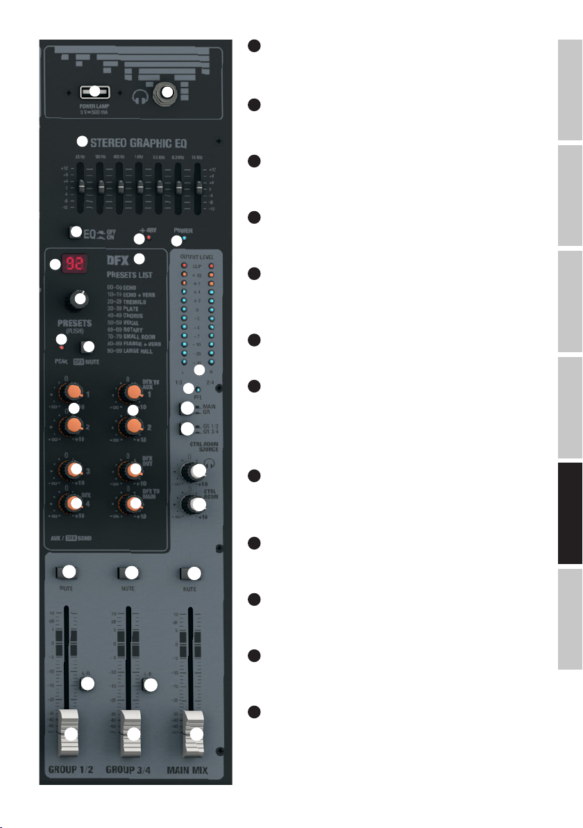
84
EQ ON/OFF
Przycisk do włączania i wyłączania korektora dźwięku sumy kanałów (nr 83). Korektor
dźwięku jest włączony we wciśniętej pozycji i wyłączony w niewciśniętej pozycji.
81
82
85
WSKAŹNIK LED +48 V
Dopóki zasilanie phantom pulpitu mikserskiego jest włączone, wskaźnik LED +48 V
83
świeci (przycisk nr 3 na tylnej ścianie).
86
POWER-LED
Dioda zasilania świeci, gdy system jest włączony i prawidłowo podłączony do sieci
elektrycznej.
87
84
87
88
85
86
89
DISPLAY DFX PRESET
Dwuznakowy wyświetlacz LED do wskazywania numeru ustawień predefiniowanych
danego efektu (00–99).
88
DFX PRESETS (PUSH)
Pokrętło-przycisk służący do wyboru i włączenia ustawień predefiniowanych danego
efektu. Należy wybrać żądane ustawienie predefiniowane poprzez ruchy pokrętłem i
FRANCAISDEUTSCHENGLISH
włączyć je poprzez naciśnięcie pokrętło-przycisku.
90
91
92
93 95
94 97
108
105
104 106 110
95
109
107
100
101
89
DFX PRESETS LIST
Lista dostępnych efektów cyfrowych.
98
90
99
DFX PEAK-LED
Gdy zapali się czerwona dioda wartości szczytowej efektów DFX, oznacza to, że
wejście wewnętrznego efektu pracuje na granicy zniekształceń. Ustawić regulator
poziomu wysyłki sygnału do efektu DFX SEND AUX 4 (nr 94) tak, aby dioda wartości
szczytowej nie zapalała się nawet w chwilach szczytowych poziomów przekazywanego sygnału.
103
91
DFX MUTE
Nacisnąć krótko przycisk MUTE w celu wyciszenia wewnętrznego efektu z efektami
102
DFX. Ponowne naciśnięcie przycisku spowoduje wyłączenie wyciszenia. Jeżeli efekt
jest wyciszony, dioda wartości szczytowej nr 90 świeci ciągle.
92
SEND AUX 1 & AUX 2
Regulator poziomu sygnału całkowitego składającego się z sygnałów regulowanych
111
pokrętłami poziomów AUX 1 i AUX 2 kanałów wejściowych od 1 do 23/24
93
SEND AUX 3
ITALIANOPOLSKIESPAÑOL
Regulator poziomu sygnału całkowitego składającego się z sygnałów regulowanych
pokrętłami poziomów AUX 3 kanałów wejściowych od 1 do 23/24.
94
SEND AUX 4/DFX
Regulator poziomu sygnału całkowitego składającego się z sygnałów regulowanych
pokrętłami poziomów AUX 4/DFX kanałów wejściowych od 1 do 23/24.
95
DFX TO AUX 1 & AUX 2
Regulator dodawania sygnału z efektami wewnętrznego efektu do sygnału wyprowadzanego z wyjść AUX 1 i AUX 2.
85
Page 86

96
DFX OUT
Regulator poziomu głośności sygnału efektu podłączonego do wyjścia DFX OUT.
97
DFX TO MAIN
Regulator dodawania sygnału z efektami wewnętrznego efektu na sumę kanałów MAIN MIX.
ENGLISH
98
OUTPUT LEVEL
2 x 12-segmentowy wskaźnik poziomu LED do wizualizacji poziomu sumy kanałów MAIN MIX i służący do dokładniejszego ustawienia wzmocnienia
(Gain), gdyż poziom sygnału wejściowego jest sygnalizowany na wskaźniku poziomu LED, gdy przycisk PFL odpowiedniego kanału jest wciśnięty. W
celu zminimalizowania zniekształceń dźwięku należy zmniejszyć poziom wyjściowy za pomocą regulatora poziomu MAIN MIX (nr 110) lub
zmniejszyć poziom sygnału wejściowego odpowiednim regulatorem wzmocnienia (GAIN) w momencie, gdy zapala się czerwona dioda CLIP-LED.
99
PFL-LED
DEUTSCHFRANCAIS
Dioda LED PFL zapala się, gdy jeden (lub więcej) przycisk PFL kanałów wejściowych od 1 do 23/24 zostanie wciśnięty.
100
CTRL ROOM SOURCE MAIN/GR
Przycisk wyboru źródła sygnału dotyczący sygnału wyjściowego CTRL ROOM (nr 10) wyjścia na słuchawki (nr 82). W pozycji niewciśniętej dochodzi
sygnał sumy kanałów MAIN MIX, a w pozycji wciśniętej sygnał grupowy GR1/2 lub GR3/4 (przycisk nr 101 GR 1/2 / GR 3/4).
101
CTRL ROOM SOURCE GR1/2 / GR3/4
Jeżeli przycisk CTRL ROOM SOURCE MAIN/GR (nr 100) jest wciśnięty, jako sygnał źródłowy można wybrać sygnał grupowy GR1/2 lub GR3/4
(przycisk niewciśnięty = GR1/2, przycisk wciśnięty = GR3/4).
102
CTRL ROOM LEVEL
Regulator poziomu stereofonicznego wyjścia liniowego CTRL ROOM (nr 10). Przed włączeniem podłączonego monitora odsłuchowego należy
ustawić regulator poziomu na minimum.
103
ESPAÑOL
POZIOM GŁOŚNOŚCI SŁUCHAWEK
Regulator poziomu głośności słuchawek (nr 82). Używać słuchawek o minimalnej impedancji 30 Ω, uważając, aby poziom głośności nie był zbyt
wysoki, co pozwoli uniknąć uszkodzenia słuchu spowodowanego dźwiękami o dużym natężeniu. Przed podłączeniem słuchawek należy ustawić
regulator poziomu na minimum.
104
GROUP 1/2
Regulator poziomu wyjść liniowych GROUP OUT 1 i 2 (nr 11) oraz do dodawania sygnału grupowego GROUP 1/2 do sumy kanałów MAIN MIX, gdy
przycisk GROUP 1/2 L-R znajduje się w pozycji wciśniętej (nr 105). Przed włączeniem podłączonego systemu nagłośnienia należy ustawić regulator
na minimum.
105
GROUP 1/2 L-R
Przycisk służący do przetrasowania sygnału grupowego GROUP 1/2 na sumę kanałów MAIN MIX (pozycja wciśnięta).
106
GROUP 3/4
Regulator poziomu wyjść liniowych GROUP OUT 3 i 4 (nr 11) oraz do dodawania sygnału grupowego GROUP 3/4 do sumy kanałów MAIN MIX, gdy
przycisk GROUP 3/4 L-R znajduje się w pozycji wciśniętej (nr 107). Przed włączeniem podłączonego systemu nagłośnienia należy ustawić regulator
ITALIANO POLSKI
na minimum.
107
GROUP 3/4 L-R
Przycisk służący do przetrasowania sygnału grupowego GROUP 3/4 na sumę kanałów MAIN MIX (pozycja wciśnięta).
108
GROUP 1/2 MUTE
Wcisnąć przycisk, aby wyciszyć sygnał grupowy GROUP 1/2. Po naciśnięciu przycisku wyciszania MUTE zapali się znajdująca się obok niego dioda.
Po ponownym naciśnięciu dioda zgaśnie, sygnalizując dezaktywowanie wyciszenia.
86
Page 87

109
GROUP 3/4 MUTE
Wcisnąć przycisk, aby wyciszyć sygnał grupowy GROUP 3/4. Po naciśnięciu przycisku wyciszania MUTE zapali się znajdująca się obok niego dioda.
Po ponownym naciśnięciu dioda zgaśnie, sygnalizując dezaktywowanie wyciszenia.
110
MAIN MIX
Regulator poziomu stereofonicznych wyjść liniowych MAIN MIX OUTPUT nr 5 i 6. Przestawić suwak tłumika nastawnego w górę, aby zwiększyć
głośność, lub w dół, aby ją zmniejszyć. Przed włączeniem podłączonego systemu nagłośnienia regulator należy ustawić na minimum.
111
MAIN MIX MUTE
Wcisnąć przycisk, aby wyciszyć sumę kanałów MAIN MIX. Po naciśnięciu przycisku wyciszania MUTE zapali się znajdująca się obok niego dioda. Po
ponownym naciśnięciu dioda zgaśnie, sygnalizując dezaktywowanie wyciszenia.
INSTALACJA INTERFEJSU USB
Instalacja w systemach operacyjnych Windows (Windows XP® lub nowszy):
Instalacja nie wymaga pobierania sterowników z Internetu ani stosowania sterowników znajdujących się na zewnętrznych nośnikach
pamięci. Pulpit mikserski podłączyć za pomocą dołączonego kabla USB do interfejsu USB 2.0 w komputerze. W większości przypadków
instalacja programu odbywa się automatycznie. W razie potrzeby należy ponownie uruchomić komputer. W niektórych przypadkach może
wyświetlić się okno (instalacja oprogramowania) z poleceniem zakończenia instalacji programu USB Audio CODEC. Polecenie to należy
wykonać. W menedżerze urządzeń systemu operacyjnego, w folderze „Kontrolery dźwięku, wideo i gier” pulpit mikserski pojawi się jako
„USB Audio CODEC” lub „Urządzenie audio USB” i będzie gotowy do pracy. W zależności od używanego programu do nagrywania może
okazać się konieczne wybranie pulpitu mikserskiego w oknie dialogowym „Dźwięk” („Panel sterowania” → „Sprzęt i dźwięk” → „Dźwięk”)
jako urządzenia rejestrującego i odtwarzającego.
Instalacja w systemach operacyjnych Apple (Mac OS X® 10.5 lub nowszy):
Instalacja nie wymaga pobierania sterowników z Internetu ani stosowania sterowników znajdujących się na zewnętrznych nośnikach
pamięci. Pulpit mikserski podłączyć za pomocą dołączonego kabla USB do interfejsu USB 2.0 w komputerze. Instalacja programu następuje
automatycznie. W zależności od używanego programu do nagrywania może okazać się konieczne wybranie pulpitu mikserskiego (USB Audio
CODEC) w oknie dialogowym „Dźwięk” („Ustawienia systemowe” → „Dźwięk”) jako urządzenia rejestrującego i odtwarzającego.
FRANCAISDEUTSCHENGLISH
87
ITALIANOPOLSKIESPAÑOL
Page 88

PRZYŁĄCZA, WYMIARY I MONTAŻ
Oznaczenie modelu: LDVIBZ24DC
Rodzaj produktu: analogowy pulpit mikserski
Typ: nagrywanie „na żywo”/w domu
ENGLISH
Liczba kanałów: 24
Kanały monofoniczne:
Monofoniczne wejściowe kanały mikrofonowe/
liniowe:
Monofoniczne wejściowe złącza mikrofonowe/
liniowe:
Typ monofonicznego wejścia mikrofonowego: elektronicznie symetryzowane, wykonanie niezależne
Charakterystyka częstotliwościowa monofonicz-
DEUTSCHFRANCAIS
nego wejścia mikrofonowego:
Zakres wzmocnienia monofonicznego wejścia
mikrofonowego:
Przesłuch kanałów: 90 dB
THD monofonicznego wejścia mikrofonowego: 0,0058%
Impedancja monofonicznego wejścia mikrofo-
nowego:
SNR monofonicznego wejścia mikrofonowego: 113 dB
Typ monofonicznego wejścia liniowego: elektronicznie symetryzowane, wykonanie niezależne
Zakres wzmocnienia monofonicznego wejścia
liniowego:
THD monofonicznego wejścia liniowego: 0,0045%
Impedancja monofonicznego wejścia liniowego: 21 kΩ
SNR monofonicznego wejścia liniowego: 116 dB
Korektor dźwięku kanału monofonicznego (tony
wysokie):
ESPAÑOL
Korektor dźwięku kanału monofonicznego (tony
średnie):
Korektor dźwięku kanału monofonicznego (tony
niskie):
Rozcięcie kanału (Insert): kanały 1 i 8
Złącza rozcięcia kanału (Insert): gniazdo jack stereo 6,3 mm (TIP (nasadka) = Send (wysyłka sygnału)/RING (pier-
Zasilanie phantom: napięcie +48 V DC, podawane na gniazda wejściowe XLR
Filtr dolnozaporowy (Low Cut): 95 Hz
Hi-Z: wejście jack kanałów 1–4, włączane (>50 kΩ)
Kompresor: kanały 1–8
Elementy obsługi (kanały 1–16): Gain, Low Cut, High-Z (kanały 1–4), Compressor (kanały 1–8), EQ Hi, EQ Mid, EQ Mid
16
gniazdo jack stereo 6,3 mm, XLR
10–45 000 Hz
50 dB
4 kΩ
50 dB
+/- 15 dB przy 12 kHz
+/-15 dB przy 8 kHz
+/- 15 dB przy 80 Hz
ścień) = Return (powrót sygnału)
Freq, EQ Low, EQ on/off, DFX, AUX Send 1-2 pre (AUX2 pre/post switchable), AUX
Send 3-4 post, Channel Mute, Fader Routing switch (Group 1/2, Group 3/4, Main
L+R), Pan/Bal, Kanal-Fader, PFL switch
ITALIANO POLSKI
88
Page 89

Kanały stereofoniczne:
Stereofoniczne liniowe kanały wejściowe: 4
Stereofoniczne liniowe złącza wejściowe: 2 x jack stereo 6,3 mm (L mono, R) 2 x RCA (cinch)
Typ stereofonicznego wejścia liniowego: niesymetryczne
Złącze USB In/Out: USB typu B (kanał 21/22)
Charakterystyka częstotliwościowa stereofonicz-
nego wejścia liniowego:
Zakres wzmocnienia stereofonicznego wejścia
liniowego:
Przesłuch kanałów: 62dB
THD stereofonicznego wejścia liniowego: 0,0045%
Impedancja stereofonicznego wejścia liniowego: 3,7 kΩ
SNR stereofonicznego wejścia liniowego: 116 dB
Korektor dźwięku kanału stereofonicznego (tony
wysokie):
Korektor dźwięku kanału stereofonicznego (tony
średnie):
Korektor dźwięku kanału stereofonicznego (tony
średnie):
Korektor dźwięku kanału stereofonicznego (tony
niskie):
Elementy obsługi (kanały 17/18–23/24): Gain, LINE/USB -switch (Kanal 21/22), EQ Hi, EQ Mid, EQ Mid Freq, EQ Low, EQ on/off,
Sekcja Master:
Kanały AUX/Send (wysyłka do efektu): 4
Złącza AUX/Send (wysyłka do efektu): 4 x niesymetryczne gniazdo jack stereo 6,3 mm
Symetryczne stereofoniczne wyjścia Main
(główne):
Symetryczne/niesymetryczne stereofoniczne
złącza wyjściowe Main (główne):
Impedancja symetrycznych stereofonicznych
wyjść Main (głównych):
Maksymalny poziom symetrycznych (niesy-
metrycznych) stereofonicznych wyjść Main
(głównych):
Stereofoniczne wyjścia Control Room: 1
Stereofoniczne złącza wyjściowe Control Room: 2 x gniazdo jack 6,3 mm
Stereofoniczne wyjścia grupowe (GR OUT): 4
Złącza wyjść grupowych: 4 x jack 6,3 mm
Wyjście słuchawkowe: 1
Wyjściowe złącza słuchawkowe: jack stereo 6,3 mm
Minimalna impedancja słuchawek: 30Ω
Cyfrowy procesor efektów tak
Liczba programów efektów: 100
Złącze przełącznika nożnego DFX Mute: gniazdo jack 6,3 mm (przełącznik nożny opcjonalny)
Elementy obsługi sekcji Master: 7-band graphic EQ, EQ On/Off, DFX Presets, DFX Mute, AUX/DFX Send 1–4, DFX to
10–45 000 Hz
50 dB
+/- 15 dB przy 12 kHz
+/- 15 dB przy 3 kHz
+/- 15 dB przy 500 Hz
+/- 15 dB przy 80 Hz
DFX, AUX Send 1-2 pre (AUX2 pre/post switchable), AUX Send 3-4 post, Channel Mute,
Fader Routing switch (Group 1/2, Group 3/4, Main L + R), Bal, Kanal-Fader, PFL switch
2
2 x jack stereo 6,3 mm, 2 x XLR (męskie)
120Ω
22 dBu (20 dBV)
Main, DFX to Aux, Phones, CTRL, GROUP to Main -switch, Phantom Power +48 V, Main
Mix Fader, Group Fader, Power, CTRL Room Source MAIN/GR, GR1/2 - GR3/4, Group
Mute, Main Mute
FRANCAISDEUTSCHENGLISH
ITALIANOPOLSKIESPAÑOL
89
Page 90
Specyfikacja ogólna:
Wskaźniki: CLIP kanału, Sygnał kanału, PFL kanału, CLIP efekt, DFX wyświetlacz LED, Zasilanie,
Złącze lampy do pulpitu: gniazdo USB typu A, 5 V DC, maks. 500 mA
USB In/Out: USB 2.0, 16 Bit Delta-Sigma
ENGLISH
Złącze zasilania: gniazdo sieciowe IEC
Napięcie robocze: 100–240 V AC 50/60 Hz
Pobór mocy (maks.): 70 W
Bezpiecznik: T1,6AL/250 V
Zakres temperatury roboczej: od 0°C do +45°C
Zakres wilgotności roboczej: od 10% (względna) do 80% (względna), bez kondensacji
DEUTSCHFRANCAIS
Szerokość: 712 mm
Wysokość: 80 mm
Głębokość: 425 mm
Waga: 9,36 kg
Zasilanie Phantom, 2 x 12-segmentowy wskaźnik poziomu, Diody LED wyciszenia
DA: 32 kHz, 44,1 kHz, 48 kHz
AD: 8 kHz, 11,025 kHz, 16 kHz, 22,05 kHz, 32 kHz, 44,1 kHz, 48 kHz
DEKLARACJE PRODUCENTA
GWARANCJA PRODUCENTA I OGRANICZENIE ODPOWIEDZIALNOŚCI
Nasze aktualne warunki gwarancji i informacje dotyczące ograniczenia odpowiedzialności znajdą Państwo na stronie: http://www.adamhall.
com/media/shop/downloads/documents/manufacturersdeclarations.pdf. W razie konieczności skorzystania z serwisu proszę skontaktować
się z firmą Adam Hall GmbH, Daimlerstraße 9, 61267 Neu Anspach / e-mail Info@adamhall.com / +49 (0)6081 / 9419-0. W celu uzyskania
aktualnej wersji deklaracji zgodności proszę zwrócić się z zapytaniem na e-mail: info@adamhall.com.
PRAWIDŁOWA UTYLIZACJA NINIEJSZEGO PRODUKTU
(Obowiązuje w Unii Europejskiej i innych krajach europejskich stosujących system sortowania odpadów) Niniejszy symbol na produk-
ESPAÑOL
cie lub związanych z nim dokumentach wskazuje, iż urządzenie po zakończeniu okresu użytkowania nie może być utylizowane razem
ze standardowymi odpadami domowymi, aby uniknąć szkód w środowisku lub szkód na osobie powstałych w wyniku niekontrolowanego
usuwania odpadów. Niniejszy produkt należy utylizować oddzielnie od innych odpadów i przekazać do punktu recyklingu w celu ponownego
wykorzystania użytych w nim materiałów w ramach idei zrównoważonego rozwoju. Klienci prywatni otrzymują informacje w zakresie przyjaznych dla środowiska możliwości usuwania odpadów od sprzedawcy, u którego produkt został zakupiony, lub w odpowiednich placówkach
regionalnych. Użytkownicy będący przedsiębiorcami proszeni są o kontakt ze swoimi dostawcami i ewentualne sprawdzenie uzgodnionych
umownie warunków utylizacji urządzeń. Niniejszy produkt nie może być utylizowany razem z innymi odpadami przemysłowymi.
ITALIANO POLSKI
90
Page 91

ITALIANO
Avete fatto la scelta giusta!
Quest‘apparecchio è stato sviluppato e prodotto secondo elevati standard qualitativi che garantiscono un funzionamento regolare per molti anni.
Per questo motivo LD Systems, con il suo nome e la pluriennale esperienza, rappresenta un‘azienda produttrice di prodotti audio di qualità. Leggete
attentamente questo manuale d‘uso per utilizzare al meglio il vostro nuovo prodotto LD Systems.
Per maggiori informazioni su LD SYSTEMS, consultate la nostra pagina web WWW.LD-SYSTEMS.COM
MISURE PRECAUZIONALI
1. Lesen S1. Leggere attentamente il presente manuale di istruzioni.
2. Conservare tutte le indicazioni e le istruzioni in un luogo sicuro.
3. Seguire le istruzioni.
4. Rispettare tutte le avvertenze. Non rimuovere dal dispositivo le indicazioni sulla sicurezza o altre informazioni.
5. Utilizzare il dispositivo solo nei modi previsti dal manuale.
6. Utilizzare esclusivamente stativi e fissaggi stabili e adatti (per installazioni fisse). Verificare che i supporti a parete siano installati e fissati a
regola d‘arte. Verificare che il dispositivo sia installato in modo stabile e non possa cadere.
7. Durante l‘installazione, osservare le normative sulla sicurezza in vigore nel proprio Paese.
8. Non installare né azionare il dispositivo in prossimità di radiatori, accumulatori termici, stufe o altre fonti di calore. Accertarsi che il dispositivo sia
sempre installato in modo che venga raffreddato a sufficienza e non possa surriscaldarsi.
9. Non appoggiare sul dispositivo fonti di combustione, quali candele accese.
10. Le fessure di areazione non devono essere bloccate.
11. Il dispositivo è destinato all‘impiego esclusivamente in ambienti chiusi; non deve essere utilizzato nelle immediate vicinanze di acqua
(questo punto non interessa i dispositivi specifici per l‘esterno, per i quali valgono le indicazioni speciali riportate di seguito). Non portare
mai il dispositivo a contatto con materiali, liquidi o gas infiammabili.
12. Accertarsi che all‘interno del dispositivo non possa penetrare acqua per gocciolamento o spruzzo. Non collocare sul dispositivo oggetti
contenenti liquidi, quali vasi, tazze o bicchieri.
13. Assicurarsi che non sia possibile la caduta di oggetti nel dispositivo.
14. Azionare il dispositivo esclusivamente con gli accessori appositamente consigliati e previsti dal produttore.
15. Non aprire né modificare il dispositivo.
16. Una volta collegato il dispositivo, verificare tutti i cavi per evitare danni o incidenti, ad esempio per inciampo.
17. Durante il trasporto, assicurarsi che il dispositivo non possa cadere e causare possibili danni a cose e/o persone.
18. Se il dispositivo non funzionasse più correttamente, vi fosse caduto sopra del liquido o un oggetto o fosse stato danneggiato in altro
modo, spegnerlo immediatamente e staccare la spina (se si tratta di un dispositivo attivo). La riparazione del dispositivo deve essere affidata
esclusivamente a personale qualificato autorizzato.
19. Per la pulizia del dispositivo utilizzare un panno pulito.
20. Rispettare le leggi sullo smaltimento in vigore nel Paese di installazione. Al momento di smaltire l‘imballo, separare la plastica dalla
carta e dal cartone.
21. I sacchetti di plastica devono essere tenuti lontani dalla portata dei bambini.
DISPOSITIVI CON ALLACCIAMENTO DI RETE:
22. ATTENZIONE: se il cavo di rete è dotato di contatto di protezione, deve essere collegato a una presa di rete con messa a terra. Non
disattivare mai la connessione di messa a terra di un cavo di rete.
23. Non accendere il dispositivo subito dopo essere stato sottoposto a forti variazioni di temperatura (ad esempio dopo il trasporto). Umidità
e condensa potrebbero danneggiare il dispositivo. Accendere il dispositivo solo dopo che ha raggiunto la temperatura ambiente.
24. Prima di collegare il dispositivo alla presa, controllare innanzitutto se la tensione e la frequenza della rete elettrica coincidono con i
valori indicati sul dispositivo stesso. Nel caso di dispositivo munito di selettore di tensione, collegarlo alla presa unicamente se i valori del
dispositivo coincidono con quelli della rete elettrica. Se il cavo di rete o l‘adattatore di rete forniti in dotazione non sono compatibili con la
presa, rivolgersi a un elettricista.
25. Non calpestare il cavo di rete. Accertarsi che i cavi sotto tensione, in particolare della presa di rete o dell‘adattatore di rete, non vengano
pizzicati.
26. Durante il cablaggio del dispositivo, verificare sempre che il cavo di rete e l‘adattatore di rete siano costantemente accessibili. Staccare
sempre il dispositivo dall‘alimentazione di rete quando non è utilizzato o durante la pulizia. Per staccare dalla presa il cavo di rete e l‘adattatore di rete, tirare sempre dalla spina o dall‘adattatore e non dal cavo. Non toccare mai il cavo di alimentazione e l’alimentatore con le mani
umide.
27. Evitare per quanto possibile di accendere e spegnere velocemente il dispositivo per non pregiudicarne la durata.
28. NOTA IMPORTANTE: Sostituire i fusibili esclusivamente con fusibili dello stesso tipo e valore. Se un fusibile continua a saltare, rivolgersi a
un centro di assistenza autorizzato.
29. Per staccare completamente il dispositivo dalla rete elettrica, rimuovere il cavo di rete o l‘adattatore di rete dalla presa.
30. Per staccare un dispositivo provvisto di presa Volex, è prima necessario sbloccare la relativa spina Volex del dispositivo stesso. Tirando il
cavo di rete, però, il dispositivo potrebbe spostarsi e cadere, provocando danni alle persone o di altro genere. Prestare quindi la più
scrupolosa attenzione durante la posa dei cavi.
31. In caso di pericolo di caduta di fulmine, o se il dispositivo rimane inutilizzato a lungo, staccare sempre il cavo di rete e l‘adattatore di rete dalla
presa.
32. L‘installazione del dispositivo deve essere realizzata unicamente in assenza di tensione (staccare la spina dalla rete elettrica).
33. Polvere e depositi di altra natura all‘interno del dispositivo possono danneggiarlo. A seconda delle condizioni ambientali (polvere,
nicotina, nebbia ecc.) il dispositivo deve essere sottoposto a regolari interventi di manutenzione e pulizia da parte di personale specializzato
FRANCAISDEUTSCHENGLISH
ITALIANOPOLSKIESPAÑOL
91
Page 92

(senza garanzia, interventi a carico del proprietario) per evitare surriscaldamento e malfunzionamenti.
34. La distanza dai materiali infiammabili deve essere di almeno 0,5 m
35. I cavi di rete utilizzati per l’alimentazione elettrica di più dispositivi devono avere una sezione di almeno 1,5mm². I cavi impiegati
nell’Unione Europea devono essere di tipo H05VV-F o simile. Adam Hall offre cavi idonei. Tali cavi consentono di collegare più dispositivi
dalla presa di uscita POWER OUT di un apparecchio alla presa POWER IN di un altro dispositivo. La potenza assorbita complessivamente da
tutti i dispositivi non deve superare il valore indicato (v.stampigliatura sul dispositivo stesso). Aver cura di mantenere i cavi di rete quanto
ENGLISH
più possibile corti.
ATTENZIONE:
non togliere mai il coperchio di protezione perché sussiste il pericolo di scosse elettriche.
L‘interno del dispositivo non contiene parti che possono essere riparate o sottoposte a
esclusivamente a personale qualificato.
Il triangolo equilatero con il simbolo del lampo segnala la presenza di tensioni pericolose non isolate all‘interno
DEUTSCHFRANCAIS
ATTENZIONE! PRODOTTI AUDIO con LIVELLI SONORI ELEVATI!
Questo dispositivo è destinato a uso professionale. Il suo utilizzo in ambito commerciale è soggetto alle normative e alle direttive nazionali
vigenti in materia di prevenzione di infortuni. In qualità di produttore, Adam Hall è tenuto per legge a informare espressamente gli utenti
degli eventuali rischi per la salute. Danni all‘udito provocati da un’esposizione prolungata a un livello sonoro elevato: l‘utilizzo di questo
prodotto può generare elevati livelli di pressione sonora (SPL) che possono provocare danni irreparabili all‘udito di artisti, collaboratori e
spettatori. Evitare l‘esposizione prolungata a livelli sonori elevati, superiori a 90dB.
ATTENZIONE! INDICAZIONI IMPORTANTI RELATIVE AI PRODOTTI DI ILLUMINAZIONE!
1. Il prodotto è stato sviluppato per un uso professionale nel settore della tecnologia applicata a spettacoli e non è idoneo all‘impiego
ESPAÑOL
nell‘illuminazione domestica.
2. Non fissare mai direttamente il fascio di luce, nemmeno per brevi istanti.
3. Non guardare mai il fascio di luce con dispositivi ottici quali le lenti d‘ingrandimento.
4. In alcuni casi, in persone sensibili gli effetti stroboscopici possono causare attacchi epilettici! Le persone affette da epilessia devono
perciò assolutamente evitare luoghi in cui vengono impiegati effetti stroboscopici.
dell‘apparecchio che possono causare scosse elettriche.
Il triangolo equilatero con punto esclamativo segnala la presenza di importanti informazioni relative all’uso e alla
manutenzione.
Avvertimento! Questo simbolo indica superfici calde. Alcune parti della cassa potrebbero scaldarsi durante l‘impiego. Dopo aver
usato l‘apparecchiatura, lasciarla raffreddare per almeno 10 minuti prima di toccarla o trasportarla.
manutenzione da parte dell‘utente. Per gli interventi di manutenzione e di riparazione rivolgersi
INTRODUZIONE
LDVIBZ24DC - Mixer a 24 canali con sezione di effetti digitali e compressori
Il VIBZ24DC è un mixer di impiego versatile con 16ingressi microfono bilanciati provvisti di preamplificatori di qualità, filtri passa alto,
efficace equalizzatore a 3bande con medi semiparametrici e alimentazione phantom collegabile, mentre altri due possono essere utilizzati
in alternativa come canali della linea stereo.
Il compressore integrato consente di regolare in modo individuale otto canali microfono per ottenere un controllo efficace della dinamica. I
canali stereo sono dotati di equalizzatori a 4bande.
La sezione master del mixer comprende tra l’altro 2loop effetti, uscite XLR bilanciate, uscite di gruppo e di monitor, nonché una
connessione per le cuffie. Il mixer VIBZ24DC dispone anche di un’interfaccia USB per la riproduzione dei toni direttamente sul calcolatore,
di una sezione digitale di effetti con 100preset e di un raccordo per l’illuminazione da 5V del mixer.
Con funzioni importanti come il PFL, i tasti di silenziamento e il suono naturale e trasparente, il mixer VIBZ24DC è la scelta perfetta per
ITALIANO POLSKI
spettacoli dal vivo, impianti fissi e applicazioni per registrazioni amatoriali di alto livello.
92
Page 93
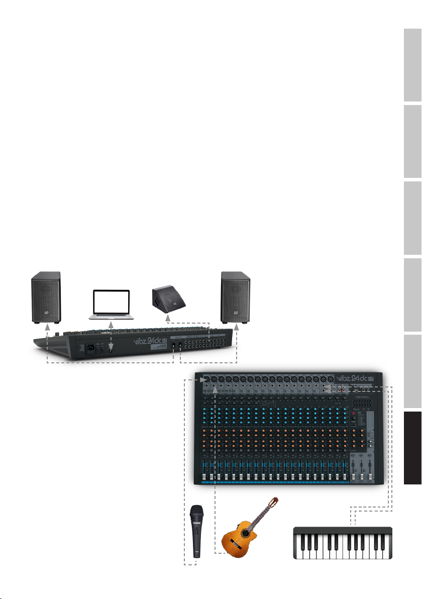
GUIDA ALL'AVVIO RAPIDO CON ESEMPIO DI CABLAGGIO
1. Verificare che il mixer e tutti i dispositivi da collegare siano spenti.
2. Collegare i dispositivi al mixer utilizzando i cavi adatti.
3. Posizionare al minimo la preamplificazione di tutti i canali, tutti i fader dei canali da 1 a 23/24 e MAIN MIX. Portare i regolatori di tutti gli
equalizzatori in posizione intermedia (si sente un clic). Posizionare al minimo i regolatori del volume dell’altoparlante attivo. Attivare l’alimentazione
phantom +48V del mixer solo se si utilizza un microfono a condensatore.
4. Accendere i dispositivi nel seguente ordine: Microfono e tastiera (o altri strumenti/dispositivi di riproduzione), mixer e per ultimi gli altoparlanti
attivi.
5. Posizionare i regolatori di guadagno dei canali in modo che il LED CLIP del canale corrispondente si accenda brevemente solo se il segnale
presente raggiunge picchi di livello. Per evitare che il LED CLIP rimanga acceso, ridurre la preamplificazione d’ingresso (GAIN).
6. Lasciare premuto l’interruttore L-R dei canali utilizzati e non premuto l’interruttore MUTE; lasciare non premuto anche l’interruttore MUTE del
canale di missaggio MAIN MIX.
7. Portare il regolatore di livello (fader) dei canali utilizzati e del canale di missaggio (MAIN MIX) approssimativamente sull’indicazione 0dB.
8. Con segnale presente (ad esempio lingua, canto, tastiera) aumentare ora il volume degli altoparlanti attivi portandolo al livello desiderato.
9. Ora è possibile eseguire la regolazione fine desiderata impostando i rapporti di volume dei canali e utilizzando gli equalizzatori, i compressori e il
dispositivo effetti.
NOTA: per spegnere i dispositivi, ricordare che occorre innanzitutto impostare al minimo il volume degli altoparlanti attivi, spegnerli e
successivamente spegnere il mixer e i dispositivi collegati.
FRANCAISDEUTSCHENGLISH
Altoparlante attivo Altoparlante attivo
Motore attivo
ITALIANOPOLSKIESPAÑOL
93
Page 94

CONNESSIONI, COMANDI E INDICATORI
ENGLISH
Presa di rete IEC con portafusibili integrato. In dotazione viene fornito un cavo di alimentazione idoneo.
NOTA IMPORTANTE: sostituire il fusibile unicamente con un fusibile dello stesso tipo e avente gli stessi valori serigrafati sul dispositivo. Se il fusibile
continua a saltare, rivolgersi a un centro di assistenza autorizzato.
DEUTSCHFRANCAIS
Interruttore di accensione/spegnimento dell’alimentazione elettrica del dispositivo (ON= acceso).
Alimentazione phantom +48V per i microfoni a condensatore senza polarizzazione. Per attivare l’alimentazione phantom degli ingressi di microfono
XLR, portare l’interruttore in posizione ON (il LED85 si accende); per disattivarla portarlo su OFF (posizione non premuta, il LED rosso si spegne).
Attivare l’alimentazione phantom solo dopo aver collegato un microfono e disattivarla prima di scollegarlo; prima di effettuare qualsiasi
cambiamento, posizionare al minimo i regolatori di volume dei canali microfono.
Presa di collegamento USB-B per la connessione a un computer con sistema operativo Windows o MAC (da Windows XP a Windows 10, MAC OS X,
registrazione e riproduzione USB 2.0).
Uscita di linea stereo bilanciata con XLR a 3poli per il collegamento di un impianto di diffusione acustica. Uscita del segnale di missaggio del mixer.
1
3
2
1
PRESA DI RETE E PORTAFUSIBILI
2
POWER ON/OFF
3
+48 V ON/OFF
4
USB IN/OUT
5
MAIN MIX OUTPUT (BAL)
4
5
8
6 7
9
12
11
10
ESPAÑOL
6
MAIN MIX OUTPUT (UNBAL)
Uscita di linea stereo non bilanciata con prese jack da 6,3mm per il collegamento di un impianto di diffusione acustica. Uscita del segnale di
missaggio del mixer.
13
7
MAIN INSERT
Due jack stereo a 3poli da 6,3mm per l’inserimento di un dispositivo esterno che elabora il segnale (compressore, porta, equalizzatore ecc.) nel
relativo canale di missaggio stereo. Per il collegamento è necessario un cavo a inserto speciale (cavo a Y, 1jack stereo su 2jack mono o XLR). La
presa è configurata nel seguente modo: PUNTA= invio, ANELLO= ritorno, MANICA= massa.
8
DFX OUT
Jack stereo a 3poli da 6,3mm per l’emissione del segnale effetti.
9
FOOT SW (DFX MUTE)
Presa jack da 6,3mm per la connessione di un interruttore a pedale che consente di attivare e disattivare a distanza la funzione di silenziamento del
ITALIANO POLSKI
dispositivo effetti (pedale opzionale).
10
CTRL ROOM
Uscite di linea non bilanciate con prese jack da 6,3mm per il collegamento di monitor di intercettazione ecc. Emissione del segnale di missaggio dei
segnali di gruppo1-2 o 3-4 del mixer, oppure del segnale PFL (commutabile).
11
GROUP OUT 1-4
Uscite di linea non bilanciate con prese jack da 6,3mm per il collegamento di impianti di diffusione ecc. Emissione dei segnali di gruppo da 1 a 4
del mixer.
94
Page 95

14
15
16 17
12
AUX SEND 1-4
Uscite di linea mono non bilanciate con presa jack da 6,3mm per l’invio del segnale a dispositivi effetti
esterni (POST fader) o a monitor da palcoscenico attivi (PRE fader).
13
INSERT CH1-CH8
Jack stereo a 3poli da 6,3mm per l’inserimento di dispositivi esterni che elaborano il segnale (compressore,
porta, ecc.) nei relativi canali da 1 a 8. Per il collegamento è necessario un cavo a inserto speciale (cavo a Y,
1jack stereo su 2jack mono o XLR). La presa è configurata nel seguente modo: PUNTA= invio, ANELLO=
ritorno, MANICA= massa.
CANALI MONO 1-16
14
MIC, CANALI 1-16
Ingressi bilanciati dei canali da 1 a 16 con prese XLR a 3poli per il collegamento di microfoni. Per azionare
i microfoni a condensatore è possibile applicare un’alimentazione phantom 48V sul pin centrale delle prese
XLR (3). Prima di inserire o disinserire i microfoni, impostare al minimo (tutto a sinistra) il regolatore di
guadagno (18) e attivare l’alimentazione phantom solo dopo aver collegato un microfono o disattivarla prima
di disinserirlo.
15
LINE IN, CANALI 1-16
Ingressi bilanciati dei canali mono da 1 a 16 con presa jack da 6,3mm per collegare un dispositivo di
riproduzione con livello di linea. Prima di collegare o scollegare i cavi della presa, posizionare al minimo (tutto
a sinistra) il regolatore del guadagno (18).
FRANCAISDEUTSCHENGLISH
18
19
21
22
23
24
25
16
LOW CUT, CANALI 1-16
Filtro passa alto per eliminare i segnali di bassa frequenza indesiderati. Soprattutto durante la trasmissione
di voce e canto, attivando la funzione LOW CUT (interruttore premuto) si possono ridurre le basse frequenze
indesiderate e aumentare così l’intelligibilità del testo. La frequenza limite è 95Hz.
20
17
CANALE HI-Z 1-4
Premendo questo pulsante, i singoli ingressi jack dei canali da 1 a 4 passano ad alta impedenza. In questo
modo si abilita l’utilizzo come canali per strumenti, ad esempio per chitarre o bassi.
18
GAIN, CANALI 1-16
Regolazione della preamplificazione dell’ingresso del microfono da 0 a 50dB e la sensibilità dell’ingresso di
linea da +15 a −35dBu. Posizionare il regolatore di guadagno in modo che il LED CLIP del canale corrispondente si accenda brevemente solo se il segnale presente raggiunge picchi di livello. Per evitare che il LED
CLIP rimanga acceso, ridurre la preamplificazione d’ingresso ovvero la sensibilità d’ingresso.
19
CANALE COMP 1-8
Compressore a regolazione continua per i canali da 1 a 8. In funzione dell’impostazione, il segnale presente
viene più o meno compresso, ovvero si limita la dinamica del segnale (regolatore tutto a sinistra=
compressore disattivato, tutto a destra= compressione massima). Con l’aumentare della compressione, il
compressore compensa automaticamente la perdita di livello. Il compressore può migliorare ad esempio la
voce di canto del segnale mixer.
20
COMP LED
Non appena il compressore è attivo, il LED della spia si accende.
21
EQ HI, CANALI 1-16
Equalizzatore acuti dei canali da 1 a 16 (12kHz, +/-15dB). Ruotare a sinistra per abbassare gli alti e a destra
per alzarli. In posizione intermedia (si sente un clic), l’equalizzatore è disattivato.
ITALIANOPOLSKIESPAÑOL
95
Page 96
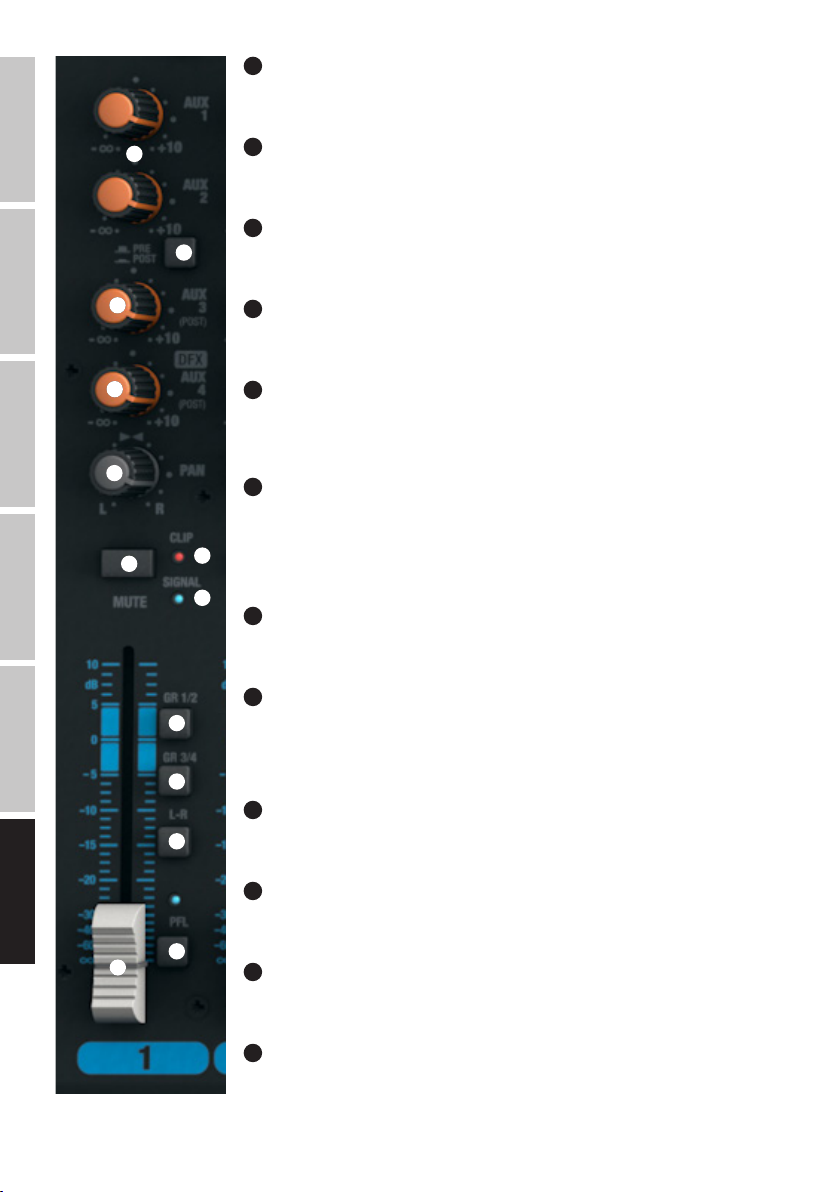
ENGLISH
22
EQ MID, CANALI 1-16
Equalizzatore medi dei canali da 1 a 16 (frequenza regolabile, +/-15dB). Ruotare a sinistra per abbassare i
medi e a destra per alzarli. In posizione intermedia (si sente un clic), l’equalizzatore è disattivato.
23
26
27
EQ MID FREQ, CANALI 1-16
Frequenza Medi. Questo regolatore consente di impostare la frequenza da aumentare o abbassare su un
valore compreso tra 200Hz a 8kHz.
24
EQ LOW, CANALI 1-16
Equalizzatore bassi dei canali da 1 a 16 (80 Hz, +/-15dB). Ruotare a sinistra per abbassare i bassi e a destra
per alzarli. In posizione intermedia (si sente un clic), l’equalizzatore è disattivato.
DEUTSCHFRANCAIS
ESPAÑOL
28
29
30
31
35
36
37
25
EQ ON/OFF, CANALI 1-16
Interruttore per l’accensione e lo spegnimento dell’equalizzatore (HI, MID e LOW). Se premuto, l’equalizzatore
è attivato altrimenti è disattivato.
26
AUX 1 + AUX 2, CANALI 1-16
Regolatore di livello del missaggio del segnale dei canali da 1 a 16 su dispositivi effetti esterni (invio effetti,
interruttore27 POST) o per l’invio di un segnale ai monitor da palcoscenico attivi (invio a monitor,
interruttore27 PRE). Utilizzare le uscita di linea AUX SEND 1 e 2 (12) per inviare il segnale.
27
AUX 1 + AUX 2 PRE/POST, CANALI 1-16
Se si sta utilizzando AUX 1 o AUX 2 per inviare il segnale a un dispositivo effetti esterno, lasciare l’interruttore
in posizione premuta POST. Il segnale verrà ora misurato dopo il fader del canale (32), dal quale pertanto
dipende. Per inviare il segnale al monitor da palcoscenico, lasciare l’interruttore in posizione PRE, non
34
premuto. Il segnale verrà ora misurato prima del fader del canale (32) e il volume del monitor da palcoscenico
potrà essere regolato indipendentemente dal livello del canale.
33
28
AUX 3 POST, CANALI 1-16
Controllo di livello del missaggio del segnale dei canali da 1 a 16 su un dispositivo effetti digitale esterno (invio
effetti, post-fader). Utilizzare l’uscita di linea AUX SEND 3 (12) per inviare il segnale.
29
LIVELLO DFX/AUX 4 POST, CANALI 1-16
Controllo di livello del missaggio del segnale del canale da 1 a 16 del dispositivo effetti digitale interno (invio
effetti post-fader). Utilizzare l’uscita di linea AUX SEND4 (12) per inviare il segnale a un dispositivo effetti
esterno. Utilizzando la presa jack AUX SEND4, il dispositivo effetti interno si disattiva automaticamente e
quindi non è utilizzabile.
30
PAN, CANALI 1-16
Utilizzare il regolatore Panorama per impostare il segnale del canale corrispondente nel campo stereo del
segnale generale (posizione centrale= percezione del segnale al centro del campo stereo).
ITALIANO POLSKI
96
31
MUTE, CANALI 1-16
Per silenziare un canale, premere l’interruttore MUTE del canale corrispondente. Al tempo stesso, il LED MUTE
dell’interruttore si accende. Disattivando la funzione di silenzio, il LED MUTE si spegne.
38
32
32
FADER, CANALI 1-16
Fader per i canali da 1 a 16. Spingere in su il fader per aumentare il volume del canale corrispondente e in
giù per ridurlo.
33
LED SEGNALE, CANALI 1-16
Il LED di segnale si accende non appena sul canale corrispondente appare un segnale audio (in base al livello
d’ingresso e all’impostazione della preamplificazione o della sensibilità d’ingresso - GAIN).
Page 97

34
LED CLIP, CANALI 1-16
Se il LED CLIP si accende in rosso, l’ingresso del canale corrispondente funziona al limite di distorsione. Posizionare il regolatore di guadagno (18)
in modo che il LED CLIP si accenda brevemente solo se il segnale presente raggiunge picchi di livello. Per evitare che il LED CLIP rimanga acceso,
ridurre la preamplificazione d’ingresso ovvero la sensibilità d’ingresso ed eventualmente il volume di un dispositivo di riproduzione.
35
GR 1/2, CANALI 1-16
Lasciare premuto l’interruttore GR 1/2 per aggiungere il canale corrispondente al gruppo di canali1 (PAN tutto a sinistra), al gruppo canali2 (PAN
tutto a destra) o con lo stesso segnale per i due gruppi di canali1 e 2 (PAN al centro). Nel contempo, i segnali di un gruppo di canali vengono
disposti sulla relativa uscita di linea GROUP OUT 1/2. Il volume globale del gruppo così costituito si imposta tramite il fader GROUP1/2 (104); se si
intende instradare i segnali audio del gruppo al canale di missaggio MAIN MIX, lasciare premuto l’interruttore L-R (105).
36
GR 3/4, CANALI 1-16
Lasciare premuto l’interruttore GR 3/4 per aggiungere il canale corrispondente al gruppo di canali3 (PAN tutto a sinistra), al gruppo canali4 (PAN
tutto a destra) o con lo stesso segnale per i due gruppi di canali3 e 4 (PAN al centro). Nel contempo, i segnali di un gruppo di canali vengono
disposti sulla relativa uscita di linea GROUP OUT 3/4. Il volume globale del gruppo così costituito si imposta tramite il fader GROUP3/4 (106); se si
intende instradare i segnali audio del gruppo al canale di missaggio MAIN MIX, lasciare premuto l’interruttore L-R (107).
37
L-R, CANALI 1-16
Per inviare direttamente un canale di ingresso (canali da 1 a 16) al canale di missaggio MAIN MIX, lasciare premuto l’interruttore L-R del canale.
38
PFL, CANALI 1-16
Premere l’interruttore PFL (Pre Fader Listening) di un canale innanzitutto per poter monitorare separatamente il segnale del canale corrispondente
utilizzando cuffie collegate all’apposita uscita PHONES (82) e indipendentemente dal fader del canale (32); in secondo luogo per poter effettuare
un’impostazione del guadagno più precisa, dal momento che il livello del segnale d’ingresso ora è indicato sulla spia di livello LED a 12segmenti del
canale di missaggio MAIN MIX. Nel contempo il LED PFL del canale corrispondente e il LED PFL sotto la spia di livello del canale di missaggio MAIN
MIX si accende. Se l’interruttore PFL torna alla sua posizione originale i LED PFL si spengono.
FRANCAISDEUTSCHENGLISH
97
ITALIANOPOLSKIESPAÑOL
Page 98

ENGLISH
DEUTSCHFRANCAIS
ESPAÑOL
CANALI STEREO 17/18 E 19/20
39
MIC, CANALI 17/18 E 19/20
Ingressi bilanciati dei canali 17/18 e 19/20 con prese XLR a 3poli per il collegamento di microfoni. I
canali17/18 e 19/20 si possono utilizzare come canali mono o stereo (XLR e jack L IN= mono / jack L e R
IN= stereo). Per azionare i microfoni a condensatore è possibile applicare un’alimentazione phantom 48V sul
39
40
41
pin centrale delle prese XLR (3). Prima di inserire o disinserire i microfoni, impostare al minimo (tutto a
sinistra) il regolatore di guadagno (41) e attivare l’alimentazione phantom solo dopo aver collegato un
microfono o disattivarla prima di disinserirlo.
40
LINE IN L/R, CANALI 17/18 E 19/20
Ingressi non bilanciati dei canali stereo17/18 e 19/20 con prese jack da 6,3mm per collegare dispositivi di
riproduzione con livello di linea (ad esempio tastiera). Se viene occupata unicamente la presa d’ingresso a
sinistra (L), il canale funziona come mono.
41
GAIN, CANALI 17/18 E 19/20
Regolazione della preamplificazione dell’ingresso del microfono da 0 a 50dB e la sensibilità dell’ingresso di
linea da +15 a −35dBu. Posizionare il regolatore di guadagno in modo che il LED CLIP del canale
corrispondente si accenda brevemente solo se il segnale presente raggiunge picchi di livello. Per evitare
che il LED CLIP rimanga acceso, ridurre la preamplificazione d’ingresso ovvero la sensibilità d’ingresso ed
eventualmente il volume del dispositivo di riproduzione.
42
EQ HI, CANALI 17/18 E 19/20
Equalizzatore acuti dei canali 17/18 e 19/20 (12kHz, +/-15dB). Ruotare a sinistra per abbassare gli alti e a
destra per alzarli. In posizione intermedia (si sente un clic), l’equalizzatore è disattivato.
43
EQ MID HI, CANALI 17/18 E 19/20
EQ MID HI, CANALI 17/18 E 19/20 (3kHz, +/-15dB). Ruotare a sinistra per abbassare i medi alti e a destra
per alzarli. In posizione intermedia (si sente un clic), l’equalizzatore è disattivato.
ITALIANO POLSKI
98
44
EQ MID LOW, CANALI 17/18 E 19/20
EQ MID LOW, CANALI 17/18 E 19/20 (500Hz, +/-15dB). Ruotare a sinistra per abbassare i medi bassi e a
destra per alzarli. In posizione intermedia (si sente un clic), l’equalizzatore è disattivato.
42
43
44
45
46
45
EQ LOW, CANALI 17/18 E 19/20
Equalizzatore bassi dei canali 17/18 e 19/20 (80Hz, +/-15dB). Ruotare a sinistra per abbassare i bassi e a
destra per alzarli. In posizione intermedia (si sente un clic), l’equalizzatore è disattivato.
46
EQ ON/OFF, CANALI 17/18 E 19/20
Interruttore per l’accensione e lo spegnimento dell’equalizzatore (HI, MID HI, MID LOW e LOW). Se premuto,
l’equalizzatore è attivato altrimenti è disattivato.
47
AUX 1 E AUX 2, CANALI 17/18 E 19/20
Regolatore di livello del missaggio del segnale dei canali da 17/18 e 19/20 su dispositivi effetti esterni (invio
effetti, interruttore48 POST) o per l’invio di un segnale ai monitor da palcoscenico attivi (invio a monitor,
interruttore48 PRE). Utilizzare le uscita di linea AUX SEND 1 e 2 (12) per inviare il segnale.
48
AUX 1 E AUX 2 PRE/POST, CANALI 17/18 E 19/20
Se si sta utilizzando AUX 1 o AUX 2 per inviare il segnale a un dispositivo effetti esterno, lasciare l’interruttore
in posizione premuta POST. Il segnale verrà ora misurato dopo il fader del canale (53), dal quale pertanto
dipende. Per inviare il segnale al monitor da palcoscenico, lasciare l’interruttore in posizione PRE, non
premuto. Il segnale verrà ora misurato prima del fader del canale (53) e il volume del monitor da palcoscenico
potrà essere regolato indipendentemente dal volume del canale.
Page 99
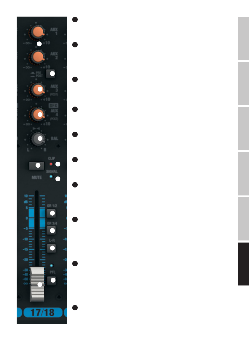
49
AUX 3 POST, CANALI 17/18 E 19/20
Regolatore di livello del missaggio del segnale dei canali da 17/18 e 19/20 su un dispositivo effetti esterno
(invio effetti, post-fader). Utilizzare l’uscita di linea AUX SEND 3 (12) per inviare il segnale.
47
48
49
50
51
52
56
57
58
50
LIVELLO DFX/AUX 4 POST, CANALI 17/18 E 19/20
Regolatore di livello del missaggio del segnale dei canali17/18 e 19/20 sul dispositivo effetti digitale interno
(invio effetti, post-fader). Utilizzare l’uscita di linea AUX SEND4 (12) per inviare il segnale a un dispositivo
effetti esterno. Utilizzando la presa jack AUX SEND4, il dispositivo effetti interno si disattiva automaticamente
e quindi non è utilizzabile.
51
BAL, CANALI 17/18 E 19/20
Il controllo BALANCE consente di impostare il rapporto del volume tra la percentuale sinistra e destra del
segnale stereo presente. Se la presa XLR o solo la presa sinistra L (MONO) dell’ingresso di linea dei canali17/18 e 19/20 è occupata, il regolatore funge da regolatore Panorama.
52
MUTE, CANALI 17/18 E 19/20
Per silenziare un canale, premere l’interruttore MUTE del canale corrispondente. Al tempo stesso, il LED MUTE
dell’interruttore si accende. Disattivando la funzione di silenzio, il LED MUTE si spegne.
53
FADER, CANALI 17/18 E 19/20
Fader per i canali 17/18 e 19/20. Spingere in su il fader per aumentare il volume del canale corrispondente e
in giù per ridurlo.
54
55
54
LED SEGNALE, CANALI 17/18 E 19/20
Il LED di segnale si accende non appena sul canale corrispondente appare un segnale audio (in base al livello
d’ingresso e all’impostazione della preamplificazione o della sensibilità d’ingresso - GAIN).
55
LED CLIP, CANALI 17/18 E 19/20
Se il LED CLIP si accende in rosso, l’ingresso del canale corrispondente funziona al limite di distorsione.
Posizionare il regolatore di guadagno (41) in modo che il LED CLIP si accenda brevemente solo se il segnale
presente raggiunge picchi di livello. Per evitare che il LED CLIP rimanga acceso, ridurre la preamplificazione
d’ingresso ovvero la sensibilità d’ingresso ed eventualmente il volume di un dispositivo di riproduzione.
56
GR 1/2, CANALI 17/18 E 19/20
Lasciare premuto l’interruttore GR 1/2 per aggiungere il canale corrispondente al gruppo di canali1 (BAL
tutto a sinistra), al gruppo canali2 (BAL tutto a destra) o con lo stesso segnale per i due gruppi di canali1 e
2 (BAL al centro). Nel contempo, i segnali di un gruppo di canali vengono disposti sulla relativa uscita di linea
GROUP OUT 1/2. Il volume globale del gruppo così costituito si imposta tramite il fader GROUP1/2 (104); se si
intende instradare i segnali audio del gruppo al canale di missaggio MAIN MIX, lasciare premuto l’interruttore
L-R (105).
FRANCAISDEUTSCHENGLISH
ITALIANOPOLSKIESPAÑOL
57
GR 3/4, CANALI 17/18 E 19/20
Lasciare premuto l’interruttore GR 3/4 per aggiungere il canale corrispondente al gruppo di canali3 (BAL
tutto a sinistra), al gruppo canali4 (BAL tutto a destra) o con lo stesso segnale per i due gruppi di canali3 e
59
53
4 (BAL al centro). Nel contempo, i segnali di un gruppo di canali vengono disposti sulla relativa uscita di linea
GROUP OUT 3/4. Il volume globale del gruppo così costituito si imposta tramite il fader GROUP3/4 (106); se si
intende instradare i segnali audio del gruppo al canale di missaggio MAIN MIX, lasciare premuto l’interruttore
L-R (107).
58
L-R, CANALI 17/18 E 19/20
Per instradare direttamente un canale d’ingresso (canali17/18 e 19/20) al canale di missaggio MAIN MIX,
lasciare premuto l’interruttore L-R del canale corrispondente.
99
Page 100

59
PFL, CANALI 17/18 E 19/20
Premere l’interruttore PFL (Pre Fader Listening) di un canale innanzitutto per poter monitorare separatamente il segnale del canale corrispondente
utilizzando cuffie collegate all’apposita uscita PHONES (82) e indipendentemente dal fader del canale (53); in secondo luogo per poter effettuare
un’impostazione del guadagno più precisa, dal momento che il livello del segnale d’ingresso ora è indicato sulla spia di livello LED a 12segmenti del
canale di missaggio MAIN MIX. Nel contempo il LED PFL del canale corrispondente e il LED PFL sotto la spia di livello del canale di missaggio MAIN
MIX si accende. Se l’interruttore PFL torna alla sua posizione originale i LED PFL si spengono.
ENGLISH
CANALI STEREO 21/22 E 23/24
60
LINE IN, CANALI 21/22 E 23/24
Ingressi di linea non bilanciati con prese RCA L ed R.
DEUTSCHFRANCAIS
ESPAÑOL
ITALIANO POLSKI
60
61
62
63
64
65
66
67
61
GAIN, CANALI 21/22 E 23/24
Regolazione della sensibilità dell’ingresso di linea da +15 a −35dBu. Posizionare il regolatore di guadagno in
modo che il LED CLIP del canale corrispondente si accenda brevemente solo se il segnale presente raggiunge
picchi di livello. Per evitare che il LED CLIP rimanga acceso, ridurre la preamplificazione d’ingresso ed
eventualmente il volume del dispositivo di riproduzione.
62
LINE/USB 21/22
Commutazione della sorgente del segnale per il canale stereo 21/22. Se non è premuto, sono attive come
sorgente di segnale le prese RCA, mentre in posizione non premuta è attiva l’interfaccia USB sul pannello
posteriore del mixer.
63
EQ HI, CANALI 21/22 E 23/24
Equalizzatore acuti dei canali 21/22 e 23/24 (12kHz, +/-15dB). Ruotare a sinistra per abbassare gli alti e a
destra per alzarli. In posizione intermedia (si sente un clic), l’equalizzatore è disattivato.
64
EQ MID HI, CANALI 21/22 E 23/24
Equalizzatore dei medi HIGH per i canali 21/22 e 23/24 (3kHz, +/-15dB). Ruotare a sinistra per abbassare i
medi alti e a destra per alzarli. In posizione intermedia (si sente un clic), l’equalizzatore è disattivato.
65
EQ MID LOW, CANALI 21/22 E 23/24
Equalizzatore dei medi LOW per i canali 21/22 e 23/24 (500Hz, +/-15dB). Ruotare a sinistra per abbassare i
medi bassi e a destra per alzarli. In posizione intermedia (si sente un clic), l’equalizzatore è disattivato.
66
EQ LOW, CANALI 21/22 E 23/24
Equalizzatore bassi dei canali 21/22 e 23/24 (80Hz, +/-15dB). Ruotare a sinistra per abbassare i bassi e a
destra per alzarli. In posizione intermedia (si sente un clic), l’equalizzatore è disattivato.
67
EQ ON/OFF, CANALI 21/22 E 23/24
Interruttore per l’accensione e lo spegnimento dell’equalizzatore (HI, MID HI, MID LOW e LOW). Se premuto,
l’equalizzatore è attivato altrimenti è disattivato.
68
AUX 1 E AUX 2, CANALI 21/22 E 23/24
Regolatore di livello del missaggio del segnale dei canali da 21/22 e 23/24 su dispositivi effetti esterni (invio
effetti, interruttore69 POST) o per l’invio di un segnale ai monitor da palcoscenico attivi (invio a monitor,
interruttore69 PRE). Utilizzare le uscita di linea AUX SEND 1 e 2 (12) per inviare il segnale.
100
69
AUX 1 E AUX 2 PRE/POST, CANALI 21/22 E 23/24
Se si sta utilizzando AUX 1 o AUX 2 per inviare il segnale a un dispositivo effetti esterno, lasciare l’interruttore
in posizione premuta POST. Il segnale verrà ora misurato dopo il fader del canale (74), dal quale pertanto dipende. Per inviare il segnale al monitor da palcoscenico, lasciare l’interruttore in posizione PRE, non premuto.
Il segnale verrà ora misurato prima del fader del canale (74) e il volume del monitor da palcoscenico potrà
essere regolato indipendentemente dal livello del canale.
 Loading...