

Page 1
USER´S MANUAL
BEDIENUNGSANLEITUNG
MANUEL D‘UTILISATION
LD PREMIUM VUE-LINE
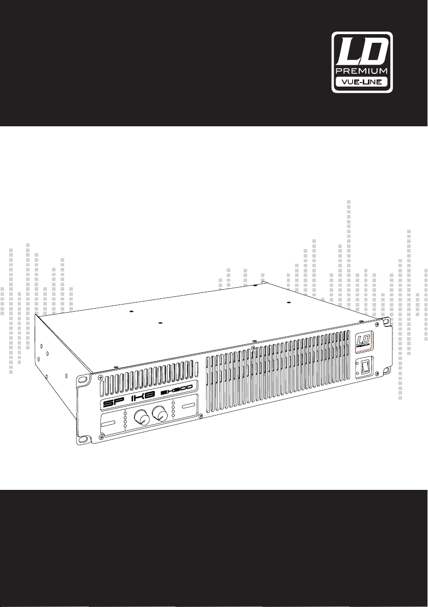
PROFESSIONAL POWER AMPLIFIER
SP1K8 / SP2K4 / SP4K / SP6K / SP44K / SP46K
Page 2

2
Thank you for choosing LD-PREMIUM!
We have designed this product to operate reliably over many years. Therefore LD-Premium guarantees for high
quality products with its name and many years of experience as a producer.
Please, take a few moments to read these instructions carefully, as we want you to enjoy your new LD-Premium
ENGLISHDEUTSCHFRANCAIS
products quickly and to the fullest.
For information about LD-Premium check out our website WWW.LD-PREMIUM.COM
Page 3
3
LD PREMIUM VUE-LINE
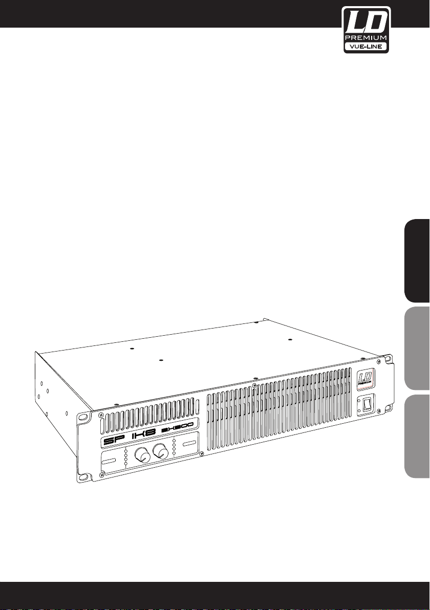
PROFESSIONAL POWER AMPLIFIER
SP1K8 / SP2K4 / SP4K / SP6K / SP44K / SP46K
ENGLISHDEUTSCHFRANCAIS
Page 4
4
PREVENTIVE MEASURES:
1. Please read the attached safety instructions as well as the following instructions carefully.
2. Please keep all the instructions.
3. Please use the device only as intended.
4. Please respect the valid waste management rules. Please deliver the packaging divided into plastic and
paper/ cardboard to the recycling management.
5. Please refer all servicing to qualified personel only, if the device is damaged, exposed to liquid/rain or if it does
not operate normally.
6. Please, do not expose to any kind of heat such as ovens, radiators, or any other devices (incl. amplifiers).
Please check for enough distance between amplifiers and walls, racks, etc. to prevent overheating.
7. After connection please check the wiring to prevent any kind of accident or damage.
Please never use any kind of damaged cable and wiring.
8. Only use authorized and stable stands, brackets, shelfs, tables etc.. for installations. Please check for
adequate stability against collapse.
ENGLISHDEUTSCHFRANCAIS
CAUTION:
To reduce the risk of electric shock, do not remove cover (or back). No user serviceable parts inside. Refer
servicing to qualified personnel.
The lightning flash with arrowhead symbol within an equilateral triangle is intended to alert the
user to the presence of uninsulated “dangerous voltage” within the product´s enclosure that may be
of sufficient magnitude to constitute a risk to persons.
The exclamation mark within an equilateral triangle is intended to alert the user to the presence of
important operating and maintenance (servicing) instructions in the literature accompanying the
appliance.
CAUTION
RISK OF ELECTRIC SHOCK
DO NOT OPEN
Page 5
5
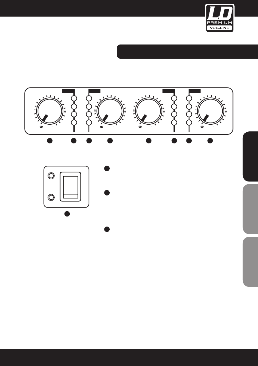
FRONT PANEL:
CH-A CH-B
-6
-9
-3
-1
-
0dB
LEVEL
1 1 1 12 2 22
ON
STBY
POWER
3
CH-A CH-B
-6
ICL
PMS
-2
TEMP
SGNL
-9
-12
-
LEVEL
1
ON
Permit independent control of each channel’s attenuation
(21 steps).
2
-3
-2
-1
0dB
SIGNAL ATTENUATION LEVEL CONTROL KNOBS
SIGNAL - This LED indicates presence of signal at the inputs.
-6
-9
-12
-
0dB
LEVEL
ICL
-3
PMS
-2
TEMP
-1
SGNL
-6
-9
-3
-2
-1
-
0dB
LEVEL
ENGLISHDEUTSCHFRANCAIS
TEMP - This LED shows temperature protection is active.
PMS - LED indicating PMS in operation (see page 13).
ICL - LED indicating Intelligent Clip Limiter in operation
(see page 13 ).
3
MAIN POWER SWITCH
Position I: Connects the amplifier‘s current feed. (Blue LED on).
Position O disconnects the Power.
Position II (optional): Stand-by Mode. The Amp‘s Power is
activated remotely via Ethernet. (Amber LED).
Page 6
6
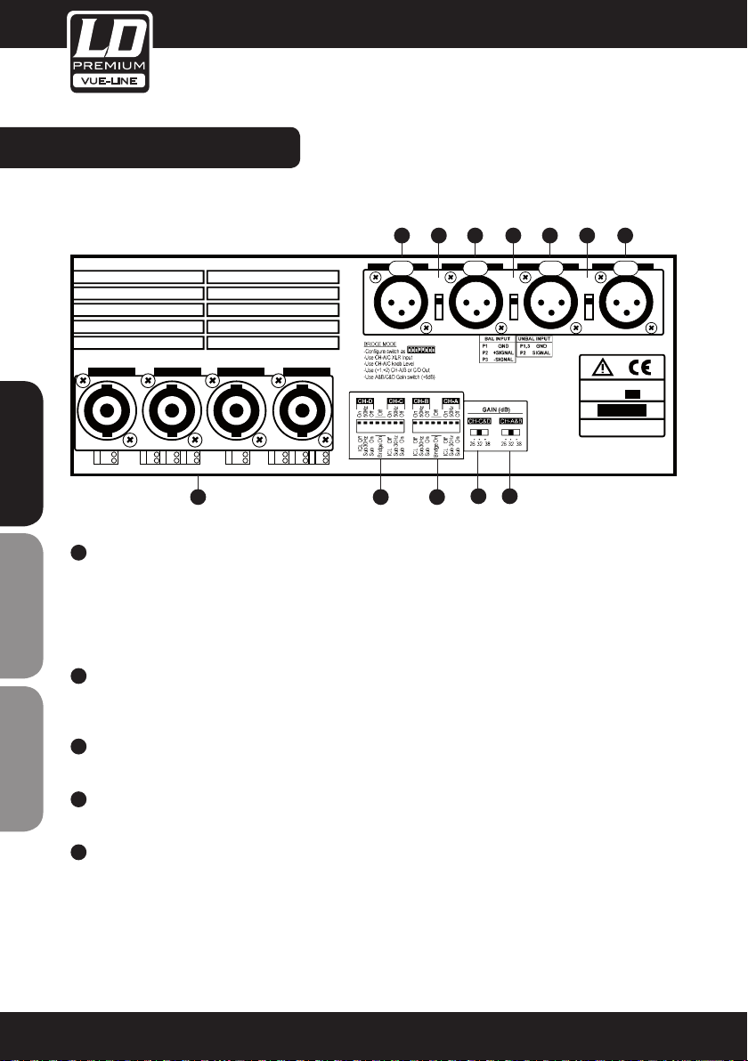
REAR PANEL:
1 2 1 2 1 2 1
IN CH-C INCH-D IN CH-B IN CH-A IN
Dual
Dual
Dual
ENGLISHDEUTSCHFRANCAIS
1
SIGNAL INPUT
OUT CH-D OUT CH-C/D OUT CH-B OUT CH-A/B
+
+
+1
-1
-
CH-B
+
+1
+2
+1
-1
-2
+2
-
-
CH-C
CH-D
BRD
+
+
CH-B
+
+1
-1
-
+
+1
+2
-1
-2
-
-
CH-A
CH-B
5 4 4
Link
D-C
+
+1
+2
-
BRD
3 3
Link
C-B
Female Neutrik® XLR Connectors for the amplifier’s signal input.
SIGNAL LINK
Signal Link: (2 channels models only) Male Neutrik® XLR Connectors for daisy chaining input signal to other
amplifiers (parallel connected to female input connectors).
2
LINK / DUAL SWITCH
In Link mode you can Link an Input to another adjacent input to use the same input signal. In Dual mode each
channel has an independent Input.
3
GAIN SELECTION SWITCH
Three position for 26, 32 or 38dB Gain, (Default setting 32dB).
4
CONFIGURATION SWITCH
Sub sonic filter, ICL and Bridge
Link
B-A
220V/2140V
50Hz/ 60Hz
SN
Fuse Inside
AT
5
SPEAKER CONNECTORS
Neutrik® Speakon to connect the speakers.
Page 7
7
INSTALLATION & OPERATING:
CONNECTIONS
The Power switch must always be on the “Off” position before plugging the amp to a properly earthed mains
socket (220-240V AC / 110V-120V AC).
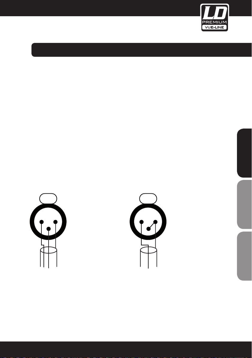
The input signal fed to the amplifier can be either balanced or un-balanced. The drawing below describes both
ways to wire an XLR connector for the purpose.
Balanced Signal: Connect pin 1 to Ground, pin 2 to Signal + (hot) and pin 3 to Signal - (cold).
Unbalanced Signal: Connect Pin 1 to Ground, pin 2 to Signal and pin 3 to Ground.
Important!: If a connection is done with a un-balanced line and pin 3 on the XLR is not connected to ground, a
6 dB loss occurs in the line and only a quarter of the amplifier power is produced.
The two channel amplifier models provides, for each channel, a female XLR Connector (Signal Input) parallelled to
a male XLR to daisy chain several amplifiers with the same signal line (LINK).
BALANCED WIRING
12
3
1- Ground
2- Signal +
3- Signal -
12
3
UNBALANCED WIRING
1- Ground
2- Signal
3- Ground
ENGLISHDEUTSCHFRANCAIS
Page 8

8
INSTALLATION & OPERATING:
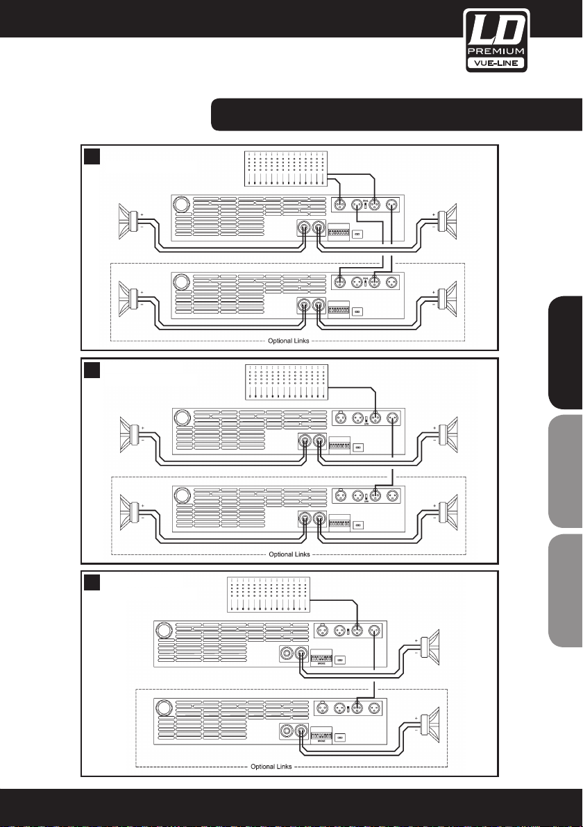
The amplifier can operate on three different configurations: DUAL, LINK or BRIDGE. The connections for the three
modes are different.
DUAL CHANNEL MODE
See Figure 3
- Switch “Off” the amp.
- Set the Mode Switch on the rear panel to “DUAL”.
- Select the chosen Gain on the back panel Switch (Default setting 32dB).
- Connect the signal lines to the female XLR connectors on all channels.
- Connect the speakers’ lines to the corresponding Speakon on the amp respecting the polarity.
- Switch “On” the amp.
- Use the level control knob on the front panel to adjust each channel independently.
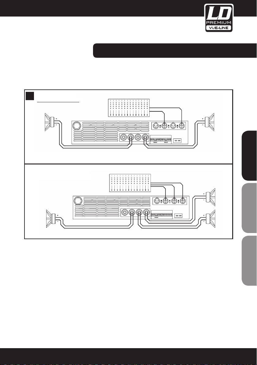
- Switch “Off” the amp.
- Set the configuration switch on the rear panel to “BRIDGE” (see page 9).
ENGLISHDEUTSCHFRANCAIS
- Select the chosen Gain on the back panel Switch (Default setting 32dB +6dB).
- Connect a signal line to input female XLR Channel “A” (or Ch-C in 4 channel models).
- Connect the speaker line to the Channel A Speakon (or Ch-C in 4 channel models) wired to +1 and +2.
In this way pin +1 is positive.
WARNING!
SP6K, SP44K and SP46K models in BRIDGE mode, have a particular connection: the speaker has to
be wired to pin +1 and -2 (pin +1 is positive). The “-“ pins in these models, do not have to be Ground!
- Switch “On” the amp.
- Use Channel-A (or Ch-C in 4 channel modes) control knob to adjust the amp’s output.
- The signalling LED groups will show the single channel status.
Page 9
9
3
4
5
Link Inputs
Bridge Mode
Dual Channel
2 CHANNEL MODELS:
ENGLISHDEUTSCHFRANCAIS
Page 10

10
4 CHANNEL MODELS:
3
4
Dual Channel
4 Channel models
Link Inputs
ENGLISHDEUTSCHFRANCAIS
Page 11
11
3
4
Dual Channel
4 Channel models
5
Link Inputs
Bridge Mode
Bridge + Dual Mode
4 CHANNEL MODELS:
ENGLISHDEUTSCHFRANCAIS
Page 12
12
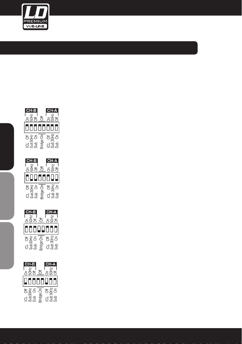
CONFIgURATION:
The amplifier has an ensemble of minidips on the back panel, which allow for the following configurations: the
highpass subsonic filter, the ICL deactivation and the bridge mode. All these configurations can be cross-set in any
way, independently from the others. The basic configuration possibilities are as follows:
STANDARD CONFIGURATION
the amplifier works without high pass subsonic filter,
Clip Limiter ICL enabled and no Bridge mode.
ENGLISHDEUTSCHFRANCAIS
SUB-SONIC FILTER ENABLED
the amplifier works with high pass subsonic filter (30Hz in this case), Clip Limiter ICL
enabled and no Bridge mode.
BRIDGE MODE
the amplifier works without high pass subsonic filter, Clip Limiter ICL enabled and
Bridge mode.
ICL CLIP LIMITER DISABLED
the amplifier works without high pass subsonic filter,
Clip Limiter ICL disabled and no Bridge mode.
Page 13
13
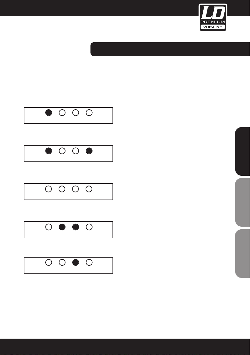
TROUBLESHOOTING:
ICLPMSTEMPSGNL
ICLPMSTEMPSGNL
ICLPMSTEMPSGNL
ICLPMSTEMPSGNL
ICLPMSTEMPSGNL
In the event of incorrect connection or misfunctioning, the amp will activate one or more of its LED to warn about
the problem.
CORRECT FUNCTION
SGNL lights to indicate signal presence.
ICL
The Intelligent Clip Limiter is operating (see page 10).
NO SIGNAL
No Input Signal is reaching the amp.
OVERHEATING
The amplifier has reached the maximum operational
temperature. Most common cause is: the normal air flow
is blocked, accumulated dirt, dust or object leaning against
the grill. Check and clean periodically.
ENGLISHDEUTSCHFRANCAIS
PMS
Several causes can trigger this LED, most common are:
- The amplifier is in power-on sequence,
where output is inhibited until the amp
circuits are ready to operate.
- The internal temperatures rise to near
thermal shutdown point due to unfavourable
operating conditions.
- Excessive mains current consumption.
Page 14
14
PROTECTION SYSTEMS:
PMS™ - POWER MANAGEMENT SYSTEM
This is a complete set of protections that monitors the main amp parameters (load status, signal input, temperature, current, etc.) in order to draw from the power supply only the precise amount of current required to maintain
safe operation during hazardous or extreme working conditions.
This system controls the amount of power that the amp delivers under three basic circumstances:
1.- The power-on sequence, where output is inhibited until the amp circuits are ready to operate. This routine is
repeated at every restart, not just when the power switch is activated.
2.- When internal temperatures rise to near thermal shutdown point due to unfavourable
operating conditions. Here the system takes control, restricting current so as to maintain operational continuity at
the precise power level which the amp is capable of withstanding at that particular moment.
3.- Excessive mains current consumption.
ENGLISHDEUTSCHFRANCAIS
This event only occurs either under laboratory conditions (long term sinusoidal signal testing with dummy loads) or,
for example, in field applications in conditions of prolonged acoustic howl-round. Here PMS takes control to avoid
any damage to the speakers and to prevent the mains breaker from tripping or the fuses blowing.
ICL2™ - INTELLIGENT CLIP LIMITER
The LD PREMIUM ICL2 is an anticlip system to avoid speaker failure and provide more acceptable sound quality
even when clipping occurs. With the ICL2 system you don‘t lose the music “punch” but the speakers are kept
under control.
SSP™ - SOA SENTRY PROTECTION
SOA Sentry protection effectively limiting the power that the amp could deliver into an incorrect load or to a direct
short-circuit. This avoids power transistor failure.
Page 15
15
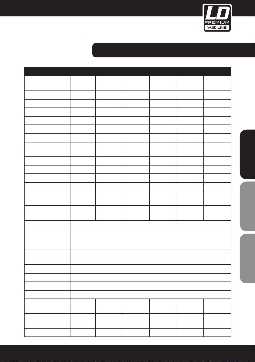
SPECIFICATIONS:
Model Name: SP1K8 SP2K4 SP4K SP6K SP44K SP46K
Output Power
@1 kHz
2 Ω 2 x 880 W 2 x 1190 W 2 x 1950 W 2 x 2950 W 4 x 980 W 4 x 1440 W
4 Ω 2 x 575 W 2 x 790 W 2 x 1380 W 2 x 2025 W 4 x 670 W 4 x 1000 W
8 Ω 2 x 325 W 2 x 460 W 2 x 810 W 2 x 1250 W 4 x 430 W 4 x 620 W
Bridge 4 Ω 1760 W 2380 W 3900 W 5900 W 2 x 1960 W 2 x 2880 W
Bridge 8 Ω 1150 W 1580 W 2760 W 4050 W 2 x 1340 W 2 x 2000 W
Output Circuity: Class H Class H Class H Class H Class H Class H
Frequenzy Range: 20 Hz - 20
kHz
THD: < 0.05 % < 0.05 % < 0.05 % < 0.05 % < 0.05 % < 0.05 %
S/N Ratio: 112 dB 113 dB 116 dB 118 dB 113 dB 116 dB
Damping Factor: > 500 > 500 > 500 > 500 > 500 > 500
Crosstalk: > 75 dB > 75 dB > 75 dB > 75 dB > 75 dB > 75 dB
Voltage Gain: 26 / 32 /
38 dB
Input Sensitivity: 2.6 / 1.3 /
0.6 V
Input Impedance: 20k ohm (balanced) / 10k ohm (unbalanced)
Protection: Soft-start, Turn-off transients, Muting at turn-on, Over-heating, DC, RF, Short-
circuit, Open or mismatched loads, Overloaded power supply, ICL Clip Limiter,
PMS, SSP
Controls: On/Off, Volume, Voltage Gain, Dual / Link switchable, Bridge/Stereo configuration
switch
Indicators: Signal, Temp, PMS (Power Management System), ICL (Intelligent Clip Limiting)
Connectors: Input: XLR / Output: Neutrik Speakon
Cooling System: 2 x continuously variable speed fan, rear to front
Power Supply: AC ~ 230V / 50 Hz
Power Consumption
@ Full Load:
Dimension
(W x H x D):
Weight (kg): 8 8 8,5 8,6 8,5 8,6
7,2 A 9,1 A 13,5 A 19 A 13,5 A 19 A
483 x 89 x
310 mm
20 Hz - 20
kHz
26 / 32 /
38 dB
3.0 / 1.5 /
0.8 V
483 x 89 x
310 mm
20 Hz - 20
kHz
26 / 32 /
38 dB
4.0 / 2.0 /
1.0 V
483 x 89 x
310 mm
20 Hz - 20
kHz
26 / 32 /
38 dB
5.0 / 2.5 /
1.3 V
483 x 89 x
310 mm
20 Hz - 20
kHz
26 / 32 /
38 dB
3.0 / 1.5 /
0.8 V
483 x 89 x
310 mm
20 Hz - 20
kHz
26 / 32 /
38 dB
3.5 / 1.8 /
0.9 V
483 x 89 x
310 mm
ENGLISHDEUTSCHFRANCAIS
Page 16

16
MANUFACTURER´S DECLARATIONS:
LIMITED wARRANTy
This Limited Warranty applies to the Adam Hall, LD Systems, Defender, Palmer and Eminence branded products.
The statutory warranty rights towards the seller are not affected by this guarantee. In fact, it justifies, additional
independent warranty claims towards Adam Hall.
Adam Hall warrants that the Adam Hall product you have purchased from Adam Hall or from an Adam Hall authorized
reseller is free from defects in materials or workmanship under normal use for a period of 2 or 3 years from the
date of purchase.
The Limited Warranty Period starts on the date of purchase. In order to receive warranty services you are required to
provide proof of the purchase date. Your dated sales or delivery receipt, showing the date of purchase, is your proof
of the purchase date. Should products of the brands named above be in need of repair within the limited warranty
period, you are entitled to warranty services according to the terms and conditions stated in this document.
ENGLISHDEUTSCHFRANCAIS
This Limited Warranty extends only to the original purchaser of this Adam Hall branded product and is not transferable to anyone, who obtains ownership of the Adam Hall branded product from the original purchaser. During the Limited Warranty Period, Adam Hall will repair or replace the defective component parts or the product. All component
parts or hardware products removed under this Limited Warranty become the property of Adam Hall.
In the unlikely event that your Adam Hall product has a recurring failure, Adam Hall, at its discretion, may elect to
provide you with a replacement unit of Adam Hall´s choice that is at least equivalent to your Adam Hall branded
product in hardware performance.
Adam Hall does not warrant that the operation of this product will be uninterrupted or error-free. Adam Hall is not
responsible for damage that occurs as a result of your failure to follow the instructions included with the Adam Hall
branded product.
This Limited Warranty does not apply,
- to wear parts (e.g. accumulator)
- to any product from which the serial number has been removed or that has been damaged or rendered defective
as the result of an accident
- in case of, misuse, abuse, or other external causes
- by operation outside the usage parameters stated in the user´s documentation shipped with the product
- by use of spare parts not manufactured or sold by Adam Hall
- by modification or service by anyone other than Adam Hall
These terms and conditions constitute the complete and exclusive warranty agreement between you and Adam Hall
regarding the Adam Hall branded product you have purchased.
Page 17
17
LIMITATION OF LIABILITy
If your Adam Hall branded hardware product fails to work as warranted above, your sole and exclusive remedy
shall be repair or replacement. Adam Halls’ maximum liability under this limited warranty is expressly limited to the
lesser of the price you have paid for the product or the cost of repair or replacement of any hardware components
that malfunction in conditions of normal use.
Adam Hall is not liable for any damages caused by the product or the failure of the product, including any lost
profits or savings or special, incidental, or consequential damages. Adam Hall is not liable for any claim made by a
third party or made by you for a third party.
This limitation of liability applies whether damages are sought, or claims are made, under this Limited Warranty or
as a tort claim (including negligence and strict product liability), a contract claim, or any other claim. This limitation
of liability cannot be waived or amended by any person. This limitation of liability will be effective even if you
have advised Adam Hall of an authorized representative of Adam Hall of the possibility of any such damages. This
limitation of liability however, will not apply to claims for personal injury.
This Limited Warranty gives you specific legal rights. You may also have other rights that may vary from state to
state or from country to country. You are advised to consult applicable state or country laws for a full determination
of your rights.
REQUESTING wARRANTy-SERVICE
To request warranty service for the product, contact Adam Hall or the Adam Hall authorized reseller from which you
purchased the product.
Eg-DECLARATION OF CONFIRMITY
These products meet the essential requirements as well as the further standards of the EU Directives 199/5/EU,
89/336/EU.
CORRECT DISPOSAL OF THIS PRODUCT (ELECTRICAL WASTE)
(Applicable in the European Union and other European countries with separate collection systems)
This marking shown on the product or its literature, indicates that it should not be disposed with other household
wastes at the end of its working life. To prevent possible harm to the environment or human health from uncontrolled
waste disposal, please separate this from other types of wastes and recycle it responsibly to promote the sustainable
reuse of material resources.
Household users should contact either the retailer where they purchased this product, or their local government
office, for details on where and how they can recycle this item in an enviromentally friendly manner.
Business users should contact their supplier and check the terms and conditions of the purchase contract. This
product should not be mixed with other commercial wastes for disposal
ENGLISHDEUTSCHFRANCAIS
Page 18

18
wEEE-DECLARATION
Your LD-Systems product was developed and manufactured with high quality materials and components wich can
be recycled and/or reused. This symbol indicates that electrical and electronic equipment must be disposed of
separately from normal waste at the end of its operational lifetime.
Please dispose of this product by bringing it to your local collection point or recycling centre for such equipment.
This will help to protect the environment in which we all live.
BATTERIES AND ACCUMULATORS
The supplied batteries or rechargeable batteries can be recycled. Please dispose of them as special waste or return
them to your specialist dealer. In order to protect the environment, only dispose exhausted batteries.
ENGLISHDEUTSCHFRANCAIS
Adam Hall GmbH, all rights reserved. The technical data and the functional product characteristics can be subject
to modifications. The photocopying, the translation, and all other forms of copying of fragments or of the integrality
of this user’s manual is prohibited.
Page 19

19
ENGLISHDEUTSCHFRANCAIS
Page 20

20
Sie haben die richtige Wahl getroffen!
Diese LD-Premium Produkte werden Sie lange Jahre durch Zuverlässigkeit, Wirtschaftlichkeit und einfaches
Handling überzeugen. Dafür garantiert LD-Premium mit seinem Namen und seiner in vielen Jahren erworbenen
Kompetenz als Hersteller hochwertiger Geräte.
Nehmen Sie sich nun ein paar Minuten Zeit, diese Anleitung zu lesen. Wir möchten, dass Sie einfach
ENGLISHDEUTSCHFRANCAIS
und schnell in den Genuss dieser Technik kommen.
Mehr Informationen zu LD-SYSTEMS finden Sie auf unserer Internetseite WWW.LD-PREMIUM.COM
Page 21

21
LD PREMIUM VUE-LINE
PROFESSIONAL POWER AMPLIFIER
SP1K8 / SP2K4 / SP4K / SP6K / SP44K / SP46K
ENGLISHDEUTSCHFRANCAIS
Page 22

22
VORSICHTSMASSNAHMEN:
1. Bitte beachten Sie die Sicherheitshinweise und studieren Sie diese Anleitung sorgfältig.
2. Bewahren Sie alle Hinweise und Anleitungen sicher auf.
3. Verwenden Sie das Gerät nur in der vorgesehenen Art und Weise.
4. Beachten Sie die in Ihrem Land geltenden Entsorgungsgesetze. Trennen Sie bei der Entsorgung bitte Plastik und
Papier bzw. Kartonagen von einander.
5. Sollte Ihr Gerät nicht mehr ordnungsgemäß funktionieren, Flüssigkeiten ausgesetzt worden oder auf sonstige Art
und Weise beschädigt sein, überlassen Sie bitte jegliche Reparaturen ausschließlich autorisiertem Fachpersonal.
6. Halten Sie das Gerät von Hitzequellen wie z.B. Ofen, Heizkörper, oder sonstige Quellen (auch Verstärker) fern.
Sorgen Sie dafür dass das Gerät immer so installiert ist, dass es ausreichend gekühlt wird und nicht überhitzt.
7. Überprüfen Sie alle Verbindungen nach dem Sie das Gerät angeschlossen haben, um Schäden oder Unfälle zu
vermeiden.
8. Verwenden Sie ausschließlich stabile und passende Stative bzw. Befestigungen, wenn das Gerät fest installiert
wird. Stellen Sie sicher, dass das Gerät sicher installiert ist und nicht herunterfallen kann.
ENGLISHDEUTSCHFRANCAIS
ENGLISHDEUTSCHFRANCAIS
ACHTUNG:
Entfernen Sie niemals die Abdeckung, da sonst die Gefahr eines elektrischen Schocks besteht.
Im Inneren des Gerätes befinden sich keine Teile, die vom Bediener gewartet oder repariert werden können.
Lassen Sie Reparaturen ausschließlich von qualifiziertem Servicepersonal durchführen.
Dieses Symbol warnt vor nichtisolierten, gefährlichen Spannungen im Geräteinneren,
die einen gefährlichen Schlag verursachen können.
Dieses Symbol kennzeichnet wichtige Bedienungs- und Wartungshinweise.
CAUTION
RISK OF ELECTRIC SHOCK
DO NOT OPEN
Page 23

23
FRONTPLATTE:
CH-A CH-B
-6
-9
-3
-1
-
0dB
LEVEL
1 1 1 12 2 22
ON
STBY
POWER
3
CH-A CH-B
-6
ICL
PMS
-2
TEMP
SGNL
-9
-12
-
LEVEL
1
ON
Diese ermöglichen die Signalstärke am Ausgang in 21 Stufen zu
regeln.
2
-3
-2
-1
0dB
LAUTSTÄRKEREGLER
SIGNAL: Wachanzeige des eingehenden Signals.
LED-Anzeige leuchtet wenn der Schutz vor Überwär
TEMP:
-6
-9
-12
-
0dB
LEVEL
ICL
-3
PMS
-2
TEMP
-1
SGNL
-6
-9
-3
-2
-1
-
0dB
LEVEL
ENGLISHDEUTSCHFRANCAIS
mung eingeschaltet ist.
Die LED zeigt an, dass das PMS in Betrieb ist (siehe Seite 31)
PMS:
Die LED zeigt an, dass der Intelligent Cliplimiter arbeitet
ICL:
(siehe Seite 31).
3
HAUPTSTROMSCHALTER
Position I: Schaltet die Endstufe ein. (Blaue LED leuchtet).
Position O Schaltet die Endstufe aus.
Position II (optional): Stand-by Modus. Die Endstufe kann über
Ethernet eingeschaltet werden. (Gelbe LED).
Page 24

24
RÜCKPLATTE:
1 2 1 2 1 2 1
IN CH-C INCH-D IN CH-B IN CH-A IN
Dual
Dual
Dual
ENGLISHDEUTSCHFRANCAIS
1
EINGANGSSIGNAL
OUT CH-D OUT CH-C/D OUT CH-B OUT CH-A/B
+
+
+1
-1
-
CH-B
+
+1
+2
+1
-1
-2
+2
-
-
CH-C
CH-D
BRD
+
+
CH-B
+
+1
-1
-
+
+1
+2
-1
-2
-
-
CH-A
CH-B
5 4 4
Link
D-C
+
+1
+2
-
BRD
3 3
Link
C-B
Neutrik®-XLR Buchsen für den Signaleingang
SIGNAL LINK
Parallele XLR-Ausgänge zur Zusammenschaltung der Eingangssignale mehrerer Endstufen
(nur bei 2- Kanalmodellen).
2
LINK / DUAL SWITCH
Im Linkmodus kann ein Signaleingang mit einem anliegenden Eingang verbunden werden. Im Dualmodus hat
jeder Kanal einen eigenen Signaleingang.
3
WÄHLBARE EINGANGSPEGELWERTE
Drei Stufen für die folgenden Pegelwerte 26, 32 oder 38dB, (Werkseitige Einstellung 32dB).
4
KONFIGURATIONSSCHALTER
Subsonicfilter, ICL und Bridge (Siehe Seite 30).
Link
B-A
220V/2140V
50Hz/ 60Hz
SN
Fuse Inside
AT
5
LAUTSPRECHERANSCHLUSS
Neutrik® Speakon to connect the speakers.
Page 25

25
ANSCHLUSS & INBETRIEBNAHME:
ANSCHLÜSSE
Bevor Sie diese Einheit an eine SHUKO-Steckdose anschließen, schalten Sie den Hautstromschalter aus.
Das Eingangssignal kann entweder symmetrisch oder unsymmetrisch sein. Für den Anschluss siehe Zeichnung.
Symmetrisches Signal: Die Belegung der XLR Pins ist wie folgt: 1-Masse, 2- Positives Signal (hot), 3-Negatives
Signal (cold).
Asymetrisches Signal: Die Belegung der XLR Pins ist wie folgt: 1-Masse, 2- Signal, 3-Masse.
Achtung!: Wenn Sie ein asymetrisches Signal anschließen und Pin 3 nicht an Masse anschließen, erzeugt dies
einen Verlust von 6dB (1/4 der Leistung de Endstufe) am Ausgangssignal.
Die 2-Kanal-Endstufe verfügt über eine parallele XLR-Buchse für die Zusammenschaltung mehrerer
Endstufen.
ENGLISHDEUTSCHFRANCAIS
BALANCED WIRING
12
3
1- Ground
2- Signal +
3- Signal -
12
3
UNBALANCED WIRING
1- Ground
2- Signal
3- Ground
Page 26

26
ANSCHLUSS & INBETRIEBNAHME:
Es gibt drei Funktionsmöglichkeiten dieser Endstufe: Dual, Link und Bridge. Die Anschlüsse sind in den drei Fällen
unterschiedlich.
DUAL KANAL MODUS
Siehe Fig. 3
- Schalten Sie die Endstufe aus.
- Stellen Sie den Modusschalter auf der Rückseite auf die Position “Dual”.
- Bitte wählen Sie den Eingangspegelwert auf dem Schalter (WerkseinstellungS 32 dB).
- Schließen Sie alle Eingangssignale an ihre entsprechenden XLR-Buchsen.
- Schließen Sie die Lautsprecher an die entsprechenden Speakon an, bitte die Polarität ist beachten.
- Schalten Sie die Endstufen ein.
- Benutzen Sie die Lautstärkeregelung der entsprechenden Kanäle um den gewünschten Lautstärkepegel zu
erreichen.
- Die LED-Anzeigen geben den Status der beiden Kanäle an.
ENGLISHDEUTSCHFRANCAIS
LINK KANALMODUS
See Figure 4
- Gehen Sie wie im Dual-Channel-Modus vor, wobei das Eingangssignal mit einem angrenzenden Kanal verbunden ist.
BRIDGE KANALMODUS
Siehe Fig. 5
- Schalten Sie die Endstufe aus.
- Setzen Sie den Konfigurationsschalter auf der Rückseite auf die Position “BRIDGE” (Siehe Seite 9).
- Wählen Sie den Einganspegelwert auf dem Schalter (Werkseinstellung 32 dB).
- Schließen Sie das Eingangssignal an die XLR-Buchse “A” an (oder Kanal C bei 4-Kanalmodellen).
- Schließen Sie den Lautsprecher an den Kanal “A” Speakon (oder Kanal C bei 4-Kanalmodellen) verkabelt mit +1
und +2 (+1 ist positiv).
WARNING!
SP6K, SP44K und SP46K: Schließen Sie den Lautsprecher an den Kanal Speakon verkabelt mit +1 und -2 (+1 ist
positiv).
- Switch “On” the amp.
- Schalten Sie die Endstufen ein.
- Benutzen Sie Kanal A (oder Kanal C bei 4-Kanalmodellen) Potentiometer für die Regulierung des Endstufenaus ganges.
- Die LED-Anzeigen werden den Status des Ausgangkanals angeben.
Page 27

27
3
4
5
Link Inputs
Bridge Mode
Dual Channel
2 KANAL MODELLE:
ENGLISHDEUTSCHFRANCAIS
Page 28

28
4 KANAL MODELLE:
3
4
Dual Channel
4 Channel models
Link Inputs
ENGLISHDEUTSCHFRANCAIS
Page 29

29
3
4
Dual Channel
4 Channel models
5
Link Inputs
Bridge Mode
Bridge + Dual Mode
4 KANAL MODELLE:
ENGLISHDEUTSCHFRANCAIS
Page 30

30
KONFIgURATION:
Das Mini-dip-Ensemble auf der Rückplatte der Endstufe ermöglicht folgende Konfigurationen: der SubsonicHochpassfilter, die Aktivierung des ICL und den Bridgemodus. Diese Konfigurationen lassen sich, unabhängig
von den übrigen, in jeglicher Weise kombinieren. Die Basiskonfigurationsmöglichkeiten sind wie folgt:
STANDARD KONFIGURATION
Die Endstufe arbeitet ohne Subsonic-Hochpassfilter, Cliplimiter ICL ist eingeschaltet und
ohne Bridgemodus.
ENGLISHDEUTSCHFRANCAIS
SUBSONICFILTER EINGESCHALTET
Die Endstufe arbeitet mit Subsonic-Hochpassfilter (30Hz in diesem Fall) Cliplimiter ICL
eingeschaltet und ohne Bridgemodus.
BRIDGEMODUS
Die Endstufe arbeitet ohne Subsonic-Hochpassfilter, Cliplimiter ist eingeschaltet und
Bridgemodus.
ICL CLIPLIMITER
Die Endstufe arbeitet ohne Subsonic-Hochpassfilter, Cliplimiter ICL ist ausgeschaltet
und ohne Bridgemodus.
Page 31

31
PROBLEMLÖSUNG:
ICLPMSTEMPSGNL
ICLPMSTEMPSGNL
ICLPMSTEMPSGNL
ICLPMSTEMPSGNL
ICLPMSTEMPSGNL
Sollte sich eine Fehlfunktion ergeben, wird diese durch die LED-Anzeigen auf der Frontplatte angezeigt. Es gibt
folgende Möglichkeiten:
KORREKTES ARBEITEN
SGNL leuchtet wenn Eingangssignal vorhanden ist.
ICL
Der Intelligent Clip Limiter ist in Betrieb (Siehe Seite 10).
KEIN EINGANGSSIGNAL
Kein Eingangssignal vorhanden.
ENGLISHDEUTSCHFRANCAIS
ÜBERHITZUNG
Die Endstufe hat die maximale Arbeitstemperatur erreicht.
Die häufigste Ursache ist Verschmutzung oder Blockierung
der Luftein- und Austritte. Es ist ratsam diese regelmäßig
zu säubern.
PMS
Mehrere Ursachen können dieses LED auslösen, die
häufigsten sind:
- Die Endstufe befindet sich im Anschaltevorgang, das
Ausgangssignal wird so lange gehemmt bis die Enstufe
voll funktionsbereit ist.
- Die Innentemperatur steigt aufgrund ungünstiger
Arbeitsbedingungen nahe des Grenzwertes bei dem die
automatische Ausschaltefunktion aktiviert wird um eine
Überhitzung des Systems zu vermeiden.
- Überhöhter Netzstromverbrauch.
Page 32

SCHUTZSCHALTUNGSSYSTEME:
PMS™ - POWER MANAGEMENT SYSTEM
Vollständiges Set von Schutzfunktionen das die wichtigsten Endstufenparameter überwacht (Auslastung, Signaleingang, Temperatur und Stomstärke) um vom Netzanschluss nur die Menge Strom zu beziehen, die für den betriebssicheren Arbeitsablauf notwendig ist. Dieses System reguliert die von der Endstufe abgegebenen Leistung in 3
Fällen:
1.- Anschaltevorgang: Der Ausgang wird gehemmt bis die Endstufe voll funktionsbereit ist. Dieser Vorgang wiederholt sich bei jedem Neustart, nicht nur wenn der Leistungsschalter aktiviert wurde.
2.- Wenn die Innentemperatur aufgrund ungünstiger Arbeitsbedingungen nahe des Grenzwertes steigt, bei dem die
automatische Ausschaltefunktion aktiviert würde, um eine Überhitzung des Systems zu vermeiden.
In diesem Fall übernimmt das System die Kontrolle und reduziert die Stromzufuhr auf ein Niveau, dass die Endstufe
in dieser Situation aushalten kann.
3.- Überhöhter Stromverbrauch: Diese Situation stellt sich ausschließlich unter Laborbedingungen ein (in sinusförmigen Langzeitsignaltests mit Dummylasten oder in langanhaltenden akustischen Feedback Bedingungen. Hier
ENGLISHDEUTSCHFRANCAIS
greift das PMS System ein um eine Schädigung der Lautsprecher zu vermeiden und um zu verhindern dass der
Hauptunterbrecher ausgelöst wird oder die elektrischen Sicherungen durchbrennen.
ICL2™ - INTELLIGENT CLIP LIMITER
The LD PREMIUM ICL2 is an anticlip system to avoid speaker failure and provide more acceptable sound quality
even when clipping occurs. With the ICL2 system you don‘t lose the music “punch” but the speakers are kept
under control.
SSP™ - SOA SENTRY PROTECTION
SOA Sentry protection effectively limiting the power that the amp could deliver into an incorrect load or to a direct
short-circuit. This avoids power transistor failure.
32
Page 33

33
SPEZIFIKATIONEN:
Model Name: SP1K8 SP2K4 SP4K SP6K SP44K SP46K
Output Power
@1 kHz
2 Ω 2 x 880 W 2 x 1190 W 2 x 1950 W 2 x 2950 W 4 x 980 W 4 x 1440 W
4 Ω 2 x 575 W 2 x 790 W 2 x 1380 W 2 x 2025 W 4 x 670 W 4 x 1000 W
8 Ω 2 x 325 W 2 x 460 W 2 x 810 W 2 x 1250 W 4 x 430 W 4 x 620 W
Bridge 4 Ω 1760 W 2380 W 3900 W 5900 W 2 x 1960 W 2 x 2880 W
Bridge 8 Ω 1150 W 1580 W 2760 W 4050 W 2 x 1340 W 2 x 2000 W
Output Circuity: Class H Class H Class H Class H Class H Class H
Frequenzy Range: 20 Hz-20
kHz
THD: < 0.05 % < 0.05 % < 0.05 % < 0.05 % < 0.05 % < 0.05 %
S/N Ratio: 112 dB 113 dB 116 dB 118 dB 113 dB 116 dB
Damping Factor: > 500 > 500 > 500 > 500 > 500 > 500
Crosstalk: > 75 dB > 75 dB > 75 dB > 75 dB > 75 dB > 75 dB
Voltage Gain: 26 / 32 /
38 dB
Input Sensitivity: 2.6 / 1.3 /
0.6 V
Input Impedance: 20k ohm (balanced) / 10k ohm (unbalanced)
Protection: Soft-start, Turn-off transients, Muting at turn-on, Over-heating, DC, RF, Short-
circuit, Open or mismatched loads, Overloaded power supply, ICL Clip Limiter,
PMS, SSP
Controls: On/Off, Volume, Voltage Gain, Dual / Link switchable, Bridge/Stereo configuration
switch
Indicators: Signal, Temp, PMS (Power Management System), ICL (Intelligent Clip Limiting)
Connectors: Input: XLR / Output: Neutrik Speakon
Cooling System: 2 x continuously variable speed fan, rear to front
Power Supply: AC ~ 230V / 50 Hz
Power Consumption
@ Full Load:
Dimension
(W x H x D):
Weight (kg): 8 8 8,5 8,6 8,5 8,6
7,2 A 9,1 A 13,5 A 19 A 13,5 A 19 A
483 x 89 x
310 mm
20 Hz-20
kHz
26 / 32 /
38 dB
3.0 / 1.5 /
0.8 V
483 x 89 x
310 mm
20 Hz-20
kHz
26 / 32 /
38 dB
4.0 / 2.0 /
1.0 V
483 x 89 x
310 mm
20 Hz-20
kHz
26 / 32 /
38 dB
5.0 / 2.5 /
1.3 V
483 x 89 x
310 mm
20 Hz-20
kHz
26 / 32 /
38 dB
3.0 / 1.5 /
0.8 V
483 x 89 x
310 mm
20 Hz-20
kHz
26 / 32 /
38 dB
3.5 / 1.8 /
0.9 V
483 x 89 x
310 mm
ENGLISHDEUTSCHFRANCAIS
Page 34

34
HERSTELLERERKLÄRUNGEN:
gARANTIEBESTIMMUNGEN
Diese Garantie erstreckt sich auf die Marken Adam Hall, LD Systems, Defender, Palmer und Eminence.
Die gesetzlichen Gewährleistungsrechte gegenüber dem Verkäufer werden von dieser Garantie nicht berührt. Vielmehr begründet diese Garantie zusätzliche selbständige Ansprüche gegenüber Adam Hall.
Mit dieser Garantie stellt Adam Hall sicher, dass das von Ihnen bei Adam Hall oder einem Adam Hall Partner
erworbene Produkt bei normalem Gebrauch während des Zeitraums von 2 bzw. 5 Jahren ab Kaufdatum frei von
Material- oder Verarbeitungsfehlern ist.
Der Garantiezeitraum beginnt mit dem Datum des Kaufs.
Der Geltendmachung eines Anspruchs auf Garantieleistungen erforderliche Nachweis des Kaufdatums, erfolgt
durch die mit dem Kaufdatum versehene Quittung oder den mit dem Kaufdatum versehenen Lieferschein. Sie haben Anspruch auf den Garantieservice zu den in diesem Dokument aufgeführten Bedingungen und Bestimmungen,
falls eine Reparatur der unter den oben genanten Marken vertriebenen Produkte innerhalb des Garantiezeitraums
ENGLISHDEUTSCHFRANCAIS
erforderlich ist.
Diese Garantie gilt nur für den ursprünglichen Käufer des von Adam Hall vertriebenen Produkts und ist nicht an
Personen übertragbar, denen vom ursprünglichen Käufer das Eigentum am Adam Hall Produkt übertragen wird.
Innerhalb des Garantiezeitraums werden die fehlerhaften Komponenten oder das Produkt von Adam Hall repariert
oder ersetzt. Alle im Rahmen dieser Garantie entfernten Komponenten und Hardware-Produkte gehen in das Eigentum von Adam Hall über.
In dem unwahrscheinlichen Fall, dass bei dem von Ihnen erworbenen Adam Hall Produkt ein Fehler wiederholt auftritt, kann Adam Hall nach eigenem Ermessen entscheiden, Ihnen dieses Produkt durch ein vergleichbares Produkt
mit mindestens derselben Leistung zu ersetzen.
Adam Hall übernimmt keine Garantie für einen störungs- oder fehlerfreien Betrieb dieses Produkts. Adam Hall
übernimmt keine Verantwortung für auf eine inkorrekte Befolgung der im Lieferumfang des Adam Hall erhaltenen
Anweisungen zurückzuführende Schäden.
Diese Garantie erstreckt sich nicht auf
-Verschleißteile (z.B. Akkumulator).
-Geräte deren Seriennummer entfernt wurde oder die beschädigt oder fehlerhaft wurden als folge eines Unfalls
-nicht sachgerechter oder missbräuchlicher Verwendung oder anderer missbräuchlicher Verwendung oder anderer
äußerer Ursachen,
-Geräte die nicht entsprechend den Betriebsparametern betrieben wurden, die in den im Lieferumfang des Produkts enthaltenen Benutzerunterlagen festgelegt sind
-Geräte die aufgrund der Verwendung nicht von Adam Hall hergestellter oder vertriebener Teile repariert wurde
- Geräte die durch Änderung oder Wartung durch jemand anderen als Adam Hall getätigt wurde.
Diese Bestimmungen und Bedingungen stellen die vollständige und ausschließliche Garantievereinbarung zwischen Ihnen und Adam Hall für das von Ihnen erworbene Adam Hall Produkt dar.
Page 35

35
HAFTUNgSBESCHRÄNKUNG
Wenn das unter der Marke Adam Hall vertriebene Produkt nicht entsprechend der obigen Garantie funktioniert,
besteht Ihr alleiniger und ausschließlicher Anspruch aus dieser Garantie in der Reparatur oder dem Ersatz.
Weitergehende Gewährleistungsansprüche bleiben hiervon unberührt. Die maximale Haftung von Adam Hall im
Rahmen dieser Garantie ist ausdrückliche beschränkt auf den jeweils niedrigeren Betrag, der sich entweder aus
dem Kaufpreis für das Produkt oder aus den Reparatur- bzw. Ersatzkosten von Hardware-Komponenten, die bei
normalem Gebrauch nicht Ordnungsgemäß funktionieren, ergibt.
Adam Hall haftet aus dieser Garantie nicht für durch das Produkt oder sein versagen verursachte Schäden, einschließlich entgangener Gewinne, unterbliebener Einsparungen oder besonderer, indirekter oder Folgeschäden.
Adam Hall haftet zudem nicht für von Dritten oder von ihnen für Dritte geltend gemachte Ansprüche.
Diese Haftungsbeschränkung gilt unabhängig davon, ob Schäden gerichtlich verfolgt werden, ob Schadensersatzansprüche im Rahmen dieser Garantie oder aufgrund unerlaubter Handlungen (Einschließlich Fahrlässigkeit
und Gefährdungshaftung) oder aufgrund vertraglicher bzw. sonstiger Ansprüche gestellt werden. Diese Haftungsbeschränkung kann von keiner Person aufgehoben oder ergänzt werden. Diese Haftungsbeschränkung gilt auch
dann, wenn sie Adam Hall über die Möglichkeit derartiger Schäden informiert haben. Sie gilt jedoch nicht für
Ansprüche aus Personenschäden.
Aus dieser Garantie ergeben sich für Sie bestimmte Rechte. Möglicherweise haben Sie weitere Rechte, die Ihnen
von Staat zu Staat und von Land zu Land unterschiedlich sein können. Es ist ratsam, die entsprechenden Gesetze
des Staates bzw. Landes heranzuziehen, um Ihre Rechte umfassend zu ermitteln.
INANSPRUCHNAHME DES REPARATURSERVICE
Um den Garantieservice bzw. Reparaturservice für das Produkt in Anspruch zu nehmen, wenden Sie sich bitte an
Adam Hall oder an einen Adam Hall Partner, bei dem Sie das Produkt erworben haben.
Eg-KONFORMITÄTSERKLÄRUNg
Diese Geräte entsprechen den grundlegenden Anforderungen und den weiteren Vorgaben der Richtlinien 1999/5/
EU, 89/336/EU und 73/23/EU.
ENGLISHDEUTSCHFRANCAIS
KORREKTE ENTSORgUNg DIESES PRODUKTES
(Gültig in der Europäischen Union)
Dieses Symbol (entweder auf dem Gerät oder dem dazugehörigen Handbuch) weist darauf hin, dass das Gerät
nicht mit dem normalen Hausmüll entsorgt werden darf. Um mögliche Schäden an der Umwelt und an Personen zu
verhindern, entsorgen Sie dieses Gerät bitte fachgerecht bei einer entsprechenden Stelle für Elektromüll.
Als Privatkunde Informieren Sie sich bitte beim Hersteller oder bei Ihrer Gemeinde über die
Möglichkeiten der korrekten Entsorgung.
Als Geschäftskunde kontaktieren Sie bitte Ihren Lieferanten und prüfen Sie die Konditionen
zur Entsorgung der Geräte. Dieses Produkt sollte nicht mit anderem gewerblichen Abfall entsorgt werden.
Page 36

36
wEEE-DEKLARATION
Ihr LD-Systems Produkt wurde unter der Verwendung hochwertiger Materialien und Komponenten die wiederverwertet oder wieder verwendet werden können hergestellt. Dieses Symbol weist darauf hin, dass elektronische
Geräte nicht im normalen Hausmüll entsorgt werden dürfen. Entsorgen Sie dieses Gerät bitte fachgerecht bei
einer entsprechenden Stelle für Elektromüll und helfen Sie dabei unsere Umwelt zu schützen.
BATTERIEN UND AKKUS
Die mitgelieferten Batterien können wiederverwertet werden. Werfen Sie die Batterien daher nicht in den normalen Hausmüll sondern in gesonderte dafür vorgesehene Container. Helfen Sie, unsere Umwelt sauber zu halten.
ENGLISHDEUTSCHFRANCAIS
NOTES:
Adam Hall GmbH, alle Rechte vorbehalten. Änderungen der Technischen Daten und Produktmerkmale vorbehalten. Das Erstellen von Fotokopien, Übersetzungen und anderen Reproduktionen dieser Bedienungsanleitung
oder Teilen derselben ohne vorherige Genehmigung ist untersagt.
Page 37

37
Page 38

38
Merci d’avoir choisi LD-PREMIUM!
Nous avons conçu ce produit afin de vous offrir un matériel fiable, qui vous accompagnera durant de longues
années. En achetant l’un des produits de la marque LD-Premium vous bénéficiez de notre compétence reconnue et
de nos nombreuses années d’expérience en tant que fabricant. Notre nom est notre garantie.
ENGLISHDEUTSCHFRANCAIS
Veuillez s’il-vous-plait prendre quelques minutes pour lire attentivement ces instructions d’utilisation car nous
souhaitons que vous puissiez profiter pleinement et au plus vite de votre matériel LD-Premium.
Pour plus d’informations sur LD-Premium venez visiter notre site WWW.LD-PREMIUM.COM
Page 39

39
LD PREMIUM VUE-LINE
AMPLIFICATEUR DE PUISSANCE PROFESSIONNEL
SP1K8 / SP2K4 / SP4K / SP6K / SP44K / SP46K
ENGLISHDEUTSCHFRANCAIS
Page 40

40
PRÉCAUTIONS D’UTILISATION:
1. Veuillez lire attentivement les précautions d’utilisation et les instructions suivantes.
2. Veuillez conserver ce manuel d’utilisation.
3. Veuillez utiliser cet appareil uniquement conformément à son but d’utilisation initial.
4. Veuillez respecter les règles de traitement des déchets. Veuillez s’il-vous-plait séparer les déchets plastiques
des déchets papiers et les déposer dans un bac à ordures adéquat.
5. En cas de panne, de dommage, d’exposition de l’appareil à la pluie ou autres liquides, veuillez contacter une
personne qualifiée pour le service après-vente de nos produits.
6. Veuillez ne pas exposer ce produit à des sources de chaleur, telles que les fours, les radiateurs ou tout autre
appareil produisant de la chaleur (notamment les amplificateurs de puissance). Pour éviter les risques de
surchauffe veillez à ce que l’appareil ne soit pas placé trop près d’un mur, ou enfermé dans un boitier, pour
que la circulation de l’air ne soit pas obstruée.
7. Après avoir connecté votre appareil veuillez inspecter le câblage pour éviter les risques d’accident ou
d’avarie. Veuillez ne jamais utiliser de câbles endommagés.
8. Veuillez utiliser uniquement les accessoires et supports de fixation fournis ou recommandés par le
constructeur. Assurez vous de la stabilité de votre installation avant d’utiliser votre matériel, vous éviterez les
risques de chutes et donc de dommages de l’appareil.
ENGLISHDEUTSCHFRANCAIS
CAUTION
RISK OF ELECTRIC SHOCK
DANGER:
Pour réduire les risques de choc électrique veuillez ne pas retirer le couvercle (ou la face arrière) de l’appareil.
Les pièces situées à l’intérieur de l’appareil ne doivent pas être manipulées par l’utilisateur. Veuillez contacter
exclusivement une personne qualifiée pour le service après-vente de nos produits.
L’éclair finissant par une flèche, entouré d’un triangle équilatéral vous indique la présence à
l’intérieur du boîtier de pièces non isolées, représentant un risque de “haute tension électrique” et
pouvant par conséquent blesser les personnes.
DO NOT OPEN
Le point d’exclamation, entouré d’un triangle équilatéral, vous indique la présence d’instructions
importantes quant-à l’utilisation et à l’entretien dans la brochure fournie avec le produit.
Page 41

41
PANNEAU AVANT:
CH-A CH-B
-6
-9
-3
-1
-
0dB
LEVEL
1 1 1 12 2 22
ON
STBY
POWER
3
CH-A CH-B
-6
ICL
PMS
-2
TEMP
SGNL
-9
-12
-
LEVEL
1
ON
Réglage du niveau d’entrée indépendant sur chaque canal.
2
-3
-2
-1
0dB
ATTÉNUATEURS DE SIGNAL D’ENTRÉE CRANTÉS:
SIGNAL: indique la présence de signaux d’entrée.
signalisation par LED de temperature excessive.
TEMP:
signalisation par LED du fonctionnement du système
PMS:
-6
-9
-12
-
0dB
LEVEL
ICL
-3
PMS
-2
TEMP
-1
SGNL
-6
-9
-3
-2
-1
-
0dB
LEVEL
ENGLISHDEUTSCHFRANCAIS
PMS (voir page 45).
signalisation par LED du fonctionnement du système
ICL:
ICL (voir page 45).
3
POWER
Position I: Connecte l‘appareil au courant, (LED Bleue allumée).
Position O: Interruption de la mise sous tension.
Position II (en option): Mode stand-by, la mise sous tension
s‘effectue à distance via Ethernet, (LED Orange allumée).
Page 42

42
PANNEAU ARRIÈRE:
1 2 1 2 1 2 1
IN CH-C INCH-D IN CH-B IN CH-A IN
Dual
Dual
Dual
ENGLISHDEUTSCHFRANCAIS
1
CONNECTEURS NEUTRIK® XLR (FEMELLE)
OUT CH-D OUT CH-C/D OUT CH-B OUT CH-A/B
+
+
+1
-1
-
CH-B
+
+1
+2
+1
-1
-2
+2
-
-
CH-C
CH-D
BRD
+
+
CH-B
+
+1
-1
-
+
+1
+2
-1
-2
-
-
CH-A
CH-B
5 4 4
Link
D-C
+
+1
+2
-
BRD
3 3
Link
C-B
d’entrée des signaux de modulation.
Connecteurs Neutrik® XLR (mâle)
(pour modèles 2 canaux) sortie des signaux d’entrée pour la mise en parallèle d’autres amplis.
2
COMUTATEUR LINK / DUAL:
en position Link le signal d‘une entrée peut se connecter à un canal adjacent et le même signal s‘amplifie sur
deux cannaux. En position Dual, chaque canal a son propre signal indépendant.
3
COMUTATEUR DE SELECTION DE LA SENSIBILITÉ
a trois positions: 26,32 ou 38dB, (réglage usine 32dB).
4
CONFIGURATION SWITCH
filtre passe-haut / subsonique, ICL et ponté (bridge) (voir page 44).
5
SPEAKON DE SORTIE
pour le branchement des HP.
Link
B-A
220V/2140V
50Hz/ 60Hz
SN
Fuse Inside
AT
Page 43

43
INSTALLATION & MISE EN SERVICE:
BRANCHEMENT
Veillez à ce que l’interrupteur de mise en service soit en position “Off” avant de brancher l’appareil sur une prise
secteur avec mise à la terre (220V-240V AC / 110V-120V AC).
L’appareil peut fonctionner avec des signaux symétriques ou asymétriques.
La figure ci-dessous indique le câblage des connecteurs XLR pour les deux cas.
Câblage Symétrique: souder la broche 1 à la masse, la broche 2 au point chaud (+), et la broche 3 au point froid (-).
Câblage Asymétrique: souder les broches 1 et 3 à la masse, et la broche 2 au signal.
Important: Si on effectue le branchement d’un signal asymetrique sur le connecteur XLR sans relier la broche 3
à la masse, une perte de 6dB sera constatée , ce qui se traduira par une perte de 75% de la puissance de sortie.
Les amplificateurs à 2 canaux sont munis des connecteurs XLR mâle pour la mise en parallèle de plusieurs amplificateurs avec les mêmes signaux d’entrée.
ENGLISHDEUTSCHFRANCAIS
CÂBLAGE SYMÉ-
12
3
TRIQUE
1- Masse
2- Chaud
3- Froid
12
3
CÂBLAGE ASYMÉTRIQUE
1- Masse
2- Signal
3- Masse
Page 44

44
INSTALLATION & MISE EN SERVICE:
L‘amplificateur dispose de 3 modes de fonctionnement différents: STÉRÉO, PONTÉ (BRIDGE) ou LINK. Les connexions à effectuer varient d‘un mode à l‘autre.
MODE STÉRÉO
Voir Fig. 3
- Commuter l’interrupteur de mise en service sur position “Off”.
- Sélectionner le mode “DUAL” sur le panneau arrière de l’appareil.
- Selectionnez la sensibilité désirée (réglage usine 32dB).
- Brancher les signaux d’entrée aux fiches XLR femelles de tous les canaux.
- Brancher les haut-parleurs sur les Speakon en respectant les polarités.
- Commuter l’interrupteur de mise en service sur position “On”.
- Utiliser les atténuateurs d’entrée sur la face avant pour régler le niveau de sortie de chaque canal.
- Les indicateurs LED afficheront le stade de chaque canal.
MODE LINK
ENGLISHDEUTSCHFRANCAIS
Voir Fig. 4
- Utiliser l‘ampli comme en mode Dual mais avec l‘entrée de signal “linked” reliée au canal consécutif.
MODE PONTÉ (BRIDGE)
Voir Fig. 5
- Commuter l’interrupteur de mise en service sur la position “Off”.
- Sélectionner le mode BRIDGE sur le panneau arrière de l’appareil (voir page 9).
- Selectionnez la sensibilité désirée (réglage usine 32dB +6dB)
- Brancher le signal modulation sur le connecteur XLR (femelle) du canal “A”. (ou canal “C” pour les modèles 4
canaux).
- Brancher les HP sur les connecteurs Speakons (+1, +2) de sortie du canal A ou C. +1 est la borne positif dans ce
mode de fonctionnement.
AVERTISSEMENT!
Les modèles SP6K, SP44K et SP46K en mode Ponté, requièrent un branchement particulier:
brancher les HP sur les Speakons +1 et -2 (le +1 est la borne positif). Le “-“ dans ces modèles n‘est pas la masse!
- Commuter l’interrupteur de mise en service sur la position “On”.
- Utiliser les atténuateur d’entrée du Canal A (ou C pour les modèles 4 canaux) pour ajuster le signal de sortie.
- Les rangées de LED afficheront le niveau de sortie.
Page 45

45
3
4
5
Mode Link
Mode ponté
Mode stéréo
MODÈLES 2 CANAUX:
ENGLISHDEUTSCHFRANCAIS
Page 46

46
MODÈLES 4 CANAUX:
ENGLISHDEUTSCHFRANCAIS
Page 47

47
3
4
Mode Stéréo
Modèles 4 canaux
5
Mode Link
Mode ponté
Mode ponté et stéréo
MODÈLES 4 CANAUX:
ENGLISHDEUTSCHFRANCAIS
Page 48

48
CONFIgURATION:
L‘amplificateur a un ensemble d‘interrupteurs sur la face arrière qui permettent la configuration des éléments
suivants: filtre passe-hauts-subsonique, désactivation du systeme anti-écrêtage (ICL) et ponté des canaux, (bridge
mode). Toutes ces configurations peuvent s‘ajuster individuellement, de façon indépendante. Les possibilités
basiques de ces configurations peuvent être:
CONFIGURATION STANDARD
l‘amplificateur travaille sans le filtre passe-hauts/subsonique, le limiteur d‘écrêtage ICL
est activé et la configuration ponté désactivée.
ENGLISHDEUTSCHFRANCAIS
FILTRE SUBSONIQUE ACTIVÉ:
le filtre passe-hauts/subsonique est activé, le limiteur d‘écrêtage ICL est activé et la
configuration ponté désactivée.
PONTÉ ACTIVÉ:
le filtre passe-hauts/subsonique est désactivée, le limiteur d‘écrêtage ICL est activé et
la configuration ponté activée.
ICL DEACTIVÉ:
le filtre passe-hauts/subsonique est désactivée, le limiteur d‘écrêtage ICL est désactivée et la configuration ponté désactivée.
Page 49

49
DySFONCTIONNEMENTS ÉVENTUELS:
ICLPMSTEMPSGNL
ICLPMSTEMPSGNL
ICLPMSTEMPSGNL
ICLPMSTEMPSGNL
ICLPMSTEMPSGNL
En cas d’utilisation incorrecte ou de dysfonctionnement, une ou plusieurs LED seront allumées pour indiquer la
nature du problème.
FONCTIONNEMENT CORRECT:
SGNL Diode Verte allumée
ICL
Fonctionnement du limiteur intelligent d‘écretage
(voir page 10).
AUCUN SIGNAL N’ARRIVE À L’AMPLI.
ENGLISHDEUTSCHFRANCAIS
SURCHAUFFE
l’amplificateur a atteint sa plus haute température interne
admissible. Le plus souvent ceci est dû à un blocage ou à
l’obturation des voies de ventilation.
PMS
PMS Diode Orange allumée. Plusieurs anomalies peuvent
déclencher cet affichage. Les plus courantes sont:
- L‘ampli se trouve en situation de mise sous tension et
les sorties se trouvent inhabilitées jusqu‘à ce que tous les
circuits soient prêts a fonctionner.
- L‘ensemble de la température interne de l‘ampli
s‘approche du point de mise en attente à cause de conditions de fonctionnement défavorables.
- Consommation de courant excessif.
Page 50

50
CIRCUITS DE PROTECTION:
PMS™ - POWER MANAGEMENT SYSTEM
Ceci est un ensemble complet de protections qui surveillent les paramètres principaux de l‘ampli: état de
l‘impédance (charge), signal d‘entrée, température, courant, etc. pour obtenir de l‘alimentation la quantité
précise minimum de courant et ainsi permettre à l‘ampli de continuer à fonctionner en sécurité dans des conditions extrêmes, ou voire dangereuses au maintien de son intégrité électronique. Ce système contrôle la quantité de
courant que l‘ampli peut utiliser dans les circonstances suivantes:
1.- Lors de la mise sous tension, la sortie est coupée jusqu‘a ce que l‘ampli soit prêt à 100% dans tous ses
circuits. Ce processus est repeté, non seulement a la mise en marche, mais chaque fois que l‘ampli se remet en
fonctionnement.
2.- Quand la température interne de l‘ampli est proche de la coupure automatique de sécurité, (thermal shutdown), dans des conditions de fonctionnement adverses. Dans ce cas, le système prend le contrôle, et oblige
l‘alimentation a ne délivrer que le courant nécessaire à maintenir le fonctionnement, au niveau que l‘ampli est
capable de maintenir à ce moment précis, dans des conditions données.
3.- Dans le cas de consommation excessive de courant. Cette éventualité ne se présente que dans des conditions
ENGLISHDEUTSCHFRANCAIS
de laboratoire lors de tests prolongés avec des signaux sinusoïdaux ou dans les cas de réalimentation acoustique
prolongée sur la scène. Ici le PMS prend le contrôle pour éviter d‘endommager les haut-parleurs, de faire sauter
les systèmes de protection
ICL™ - LIMITEUR INTELLIGENT D‘ÉCRÊTAGE
Le ICL2 de LD PREMIUM est un système anti-écrêtage qui permet un rendement des haut-parleurs optimisé et
offre un meilleur résultat auditif quand l‘écrêtage est présent. Le ICL2 permet à la musique de garder son punch
mais sauvegarde les haut-parleurs.
SSP™ - SOA SENTRY PROTECTION
Le SOA est un système sentinelle qui limite de manière efficace le courant que l‘ampli peut donner sous une
charge inadéquate ou sous court-circuit direct. Ce système protége les transistors de sortie.
Page 51

51
CARACTÉRISTIQUES DES SYSTÈMES
Model Name: SP1K8 SP2K4 SP4K SP6K SP44K SP46K
Output Power
@1 kHz
2 Ω 2 x 880 W 2 x 1190 W 2 x 1950 W 2 x 2950 W 4 x 980 W 4 x 1440 W
4 Ω 2 x 575 W 2 x 790 W 2 x 1380 W 2 x 2025 W 4 x 670 W 4 x 1000 W
8 Ω 2 x 325 W 2 x 460 W 2 x 810 W 2 x 1250 W 4 x 430 W 4 x 620 W
Bridge 4 Ω 1760 W 2380 W 3900 W 5900 W 2 x 1960 W 2 x 2880 W
Bridge 8 Ω 1150 W 1580 W 2760 W 4050 W 2 x 1340 W 2 x 2000 W
Output Circuity: Class H Class H Class H Class H Class H Class H
Frequenzy Range: 20 Hz-20
kHz
THD: < 0.05 % < 0.05 % < 0.05 % < 0.05 % < 0.05 % < 0.05 %
S/N Ratio: 112 dB 113 dB 116 dB 118 dB 113 dB 116 dB
Damping Factor: > 500 > 500 > 500 > 500 > 500 > 500
Crosstalk: > 75 dB > 75 dB > 75 dB > 75 dB > 75 dB > 75 dB
Voltage Gain: 26 / 32 /
38 dB
Input Sensitivity: 2.6 / 1.3 /
0.6 V
Input Impedance: 20k ohm (balanced) / 10k ohm (unbalanced)
Protection: Soft-start, Turn-off transients, Muting at turn-on, Over-heating, DC, RF, Short-
circuit, Open or mismatched loads, Overloaded power supply, ICL Clip Limiter,
PMS, SSP
Controls: On/Off, Volume, Voltage Gain, Dual / Link switchable, Bridge/Stereo configuration
switch
Indicators: Signal, Temp, PMS (Power Management System), ICL (Intelligent Clip Limiting)
Connectors: Input: XLR / Output: Neutrik Speakon
Cooling System: 2 x continuously variable speed fan, rear to front
Power Supply: AC ~ 230V / 50 Hz
Power Consumption
@ Full Load:
Dimension
(W x H x D):
Weight (kg): 8 8 8,5 8,6 8,5 8,6
7,2 A 9,1 A 13,5 A 19 A 13,5 A 19 A
483 x 89 x
310 mm
20 Hz-20
kHz
26 / 32 /
38 dB
3.0 / 1.5 /
0.8 V
483 x 89 x
310 mm
20 Hz-20
kHz
26 / 32 /
38 dB
4.0 / 2.0 /
1.0 V
483 x 89 x
310 mm
20 Hz-20
kHz
26 / 32 /
38 dB
5.0 / 2.5 /
1.3 V
483 x 89 x
310 mm
20 Hz-20
kHz
26 / 32 /
38 dB
3.0 / 1.5 /
0.8 V
483 x 89 x
310 mm
20 Hz-20
kHz
26 / 32 /
38 dB
3.5 / 1.8 /
0.9 V
483 x 89 x
310 mm
ENGLISHDEUTSCHFRANCAIS
Page 52

52
DÉCLARATIONS DU FABRICANT:
gARANTIE LIMITÉE:
Cette garantie limitée s’applique aux produits de la marque Adam Hall, LD Systems, Defender, Palmer et Eminence.
Les droits inhérents à la garantie légale vis-à-vis du revendeur ne sont pas affectés par cette garantie. En fait elle
justifie d’une garantie supplémentaire indépendante auprès de la société Adam Hall.
La société Adam Hall garantit que le produit que vous avez acheté Adam Hall ou à l’un de ses revendeurs officiels,
est exempt de défaut matériel et d’usinage pour une durée de 2 ans (ou 5 ans pour les produits Palmer) à partir de
la date d’achat, lorsqu’il est utilisé dans des conditions normales.
La période de garantie limitée débute le jour de l’achat du produit. Pour bénéficier de cette garantie vous devez
produire une preuve d’achat sur laquelle figure la date d’achat du produit (ex : ticket de caisse daté, bon de livraison
daté…). Si un produit d´une des marques citées ci-dessus venait à nécessiter une réparation durant la période de
garantie limitée, vous aurez alors le droit de bénéficier des services de la garantie selon les termes et conditions
mentionnés par ce document.
ENGLISHDEUTSCHFRANCAIS
Cette garantie limitée ne s’applique qu’à l’acheteur initial de ce produit Adam Hall et ne peut être en aucun cas transférée à un tiers devenu propriétaire du produit. Durant la période de garantie limitée, Adam Hall s‘engage à réparer
ou remplacer les pièces défectueuses du produit. Toutes les pièces ou éléments démontés lors d‘une réparation par
Adam Hall deviennent la propriété d‘Adam Hall.
Dans le cas improbable d´un défaut récurrent, Adam Hall peut, à sa discrétion, décider de vous fournir un produit
de remplacement de son choix, dont les capacités techniques sont au moins équivalentes à celles de votre produit
initial.
Adam Hall ne garantit pas que le fonctionnement de ce produit sera exempt d‘erreur ou ininterrompu. Adam Hall ne
peut pas être rendu responsable des dégâts résultant de votre manquement à suivre les instructions d‘utilisation
fournies avec votre produit.
Cette garantie limitée ne s‘applique pas,
- aux pièces d‘usure (ex: piles)
- aux produits dont le numéro de série a été effacé ou aux produits endommagés ou rendus défectueux par
accident
- dans le cas d‘une utilisation non conforme aux conditions normales d‘utilisation, dans le cas d‘abus ou
toute autre cause externe
- dans le cas d‘un usage du produit en dehors des paramètres d‘utilisation stipulés dans la documentation
fournie avec le produit
- dans le cas de l‘usage de pièces de remplacement n‘étant pas fabriquées ou vendues par Adam Hall
- dans le cas d‘une modification du produit ou d‘une réparation par quiconque autre qu‘Adam Hall
Ces termes et conditions constituent l‘accord de garantie complet et exclusif entre vous et Adam Hall concernant le
produit de la marque Adam Hall que vous vous êtes procuré.
Page 53

53
LIMITATION DE RESPONSABILITÉ
Si votre produit Adam Hall devait ne pas fonctionner correctement, votre seul et unique dédommagement sera la
réparation du produit ou son remplacement. La responsabilité maximale imputable à Adam Hall dans le cadre de
cette garantie limitée se limite au montant le plus bas. Ce montant découle du prix d’achat du produit ou bien du
coût de la réparation ou des pièces de remplacement qui sont tombés en panne dans des conditions d’utilisation
normales.
Adam Hall n’est pas responsable des dommages causés par le produit ou par un dysfonctionnement du produit,
y compris les pertes de profits, les pertes d’épargne, et les conséquences inhérentes à ces dommages. La responsabilité d’Adam Hall ne peut pas être engagée dans le cas d’une réclamation par un tiers ou dans le cas d’une
réclamation émanant de l’acheteur initial pour le compte d’un tiers.
Cette limitation de responsabilité est valable indépendamment du fait que les dommages commis fassent l’objet
de poursuites judiciaires, qu’ils fassent l’objet de réclamation (y compris pour négligence), de réclamations
contractuelles ou tout autre réclamation. Cette limitation de responsabilité ne peut être amendée ou dérogée
par quiconque. Elle est effective même si vous aviez avisé Adam Hall ou l’un de ses représentants officiels de la
possibilité d’un tel dommage. Toutefois cette limitation de responsabilité est sans effet dans le cas de réclamations
pour dommages corporels.
Cette garantie limitée vous confère des droits légaux spécifiques. Selon votre pays, ou l’État dans lequel vous vous
trouvez, il est possible que vous disposiez d’autres droits. Veuillez consulter les lois applicables dans votre pays ou
votre État pour déterminer l’ensemble de vos droits.
FAIRE FONCTIONNER LA gARANTIE
Pour faire fonctionner la garantie sur ce produit, veuillez contacter Adam Hall ou le revendeur agréé auquel vous
avez acheté le produit.
UE-DÉCLARATION DE CONFORMITÉ
Ces produits sont conformes aux exigences essentielles des directives européennes 1999/5/EU,
89/336/EU ainsi qu’à leurs clauses additionnelles.
ENGLISHDEUTSCHFRANCAIS
ÉLIMINATION CORRECTE DES DÉCHETS (DÉCHETS ÉLECTROMÉNAGERS)
(Applicable dans l’Union Européenne et dans les autres pays européens disposant d’un système de tri des déchets)
Ce signe figurant sur le produit, ou dans la brochure jointe au produit, indique qu’il ne doit pas être jeté dans le même
bac à ordures que les déchets ménagers classiques lorsqu’il arrive en fin de vie. Pour écarter les risques de pollution
de l’environnement ou les risques d’intoxication humaine dûes à un mauvais traitement des déchets, veuillez séparer
ce produit des autres types de déchets. Il sera ainsi inséré dans la boucle du recyclage et ces composants pourront
être traités puis éventuellement réutilisés.
Nous recommandons aux particuliers de contacter leur revendeur local ou les autorités locales pour s’informer de la
meilleure façon de traiter les déchets électroménagers.
Les professionnels doivent contacter leur fournisseur et examiner avec lui les termes et conditions de leur contrat
d’achat. Ce produit ne doit pas être mélangé aux déchets industriels.
Page 54

54
DÉCLARATION DEEE
Votre produit LD-Systems a été développé et fabriqué avec des matériaux et des composants de haute qualité qui
peuvent être recyclés voire réutilisés. Ce signe figurant sur le produit ou dans la brochure jointe au produit indique
qu’il ne doit pas être jeté dans le même bac à ordures que les déchets ménagers classiques lorsqu’il arrive en fin
de vie.
Veuillez s’il-vous-plait disposer de ce produit auprès d’un point de collecte officiel des déchets ou d’un centre de
recyclage pour les produits de ce type.
En agissant ainsi vous participez à la préservation de l’environnement dans lequel nous vivons tous.
PILES ET BATTERIES
Les piles ou les piles rechargeables fournies avec ce produit peuvent être recyclées. Veuillez les jeter dans un
bac spécialement dédié aux déchets de ce type, ou bien retournez les à un revendeur spécialisé. Pour protéger
l’environnement, ne jetez que les piles vides.
ENGLISHDEUTSCHFRANCAIS
Adam Hall GmbH, tous droits réservés. Les données techniques et les caractéristiques fonctionnelles du produit
peuvent être sujettes à modification. La photocopie, la traduction ainsi que toutes autres formes de copies, de tout
ou partie, de ce manuel d’utilisation sont prohibées.
Page 55

55
ENGLISHDEUTSCHFRANCAIS
Page 56

WWW.LD-PREMIUM.COM
Adam Hall gmbH | Daimlerstrasse 9 | 61267 Neu-Anspach | Germany
Tel. +49(0)6081/9419-0 | Fax +49(0)6081/9419-1000
web : www.adamhall.com | e-mail : mail@adamhall.com
 Loading...