

Page 1
c
WWW.LD-SYSTEMS.COM
USERS’ MANUAL
LAX 5
5-CHANNEL MIXER
Tel: (+49) 6081 / 9419-0 Fax: (+49) 6081 / 43280
All rights reserved to Adam Hall. All features and content might be changed
without prior notice. Photocopying, translation, or reproduction of any part of this
manual without written permission is forbidden. Copyright 2007 Adam Hall GmbH
Adam Hall GmbH
www.adamhall.com
LAX 5
www.ld-systems.com
USERS’ MANUAL
Page 2

NOTES:
LD-Systems
IMPORTANT!
Please read this manual carefully before operating
this unit for the first time.
All rights reserved to Adam Hall GmbH. All features and content might be changed
without prior notice. Photocopying, translation, or reproduction of any part of
this manual without written permission is forbidden.
Page 2
LD-Systems
Page 15
Page 3

NOTES:
SAFETY RELA TED SYMBOLS
CAUTION
RISK OF ELECTRIC SHOCK
DO NOT OPEN
This symbol, wherever used, alerts you to the presence of un-insulated and dangerous voltages within the product enclosure. These are voltages that
may be sufficient to constitute the risk of electric
shock or death.
This symbol, wherever used, alerts you to important operating and maintenance instructions.
Please read.
- Fuse
To prevent fire and damage to the product, only use
the recommended fuse type as indicated in this
manual. Do not short-circuit the fuse holder. Before
replacing the fuse, make sure that the product is
OFF and disconnected from the AC outlet.
- Protective Ground
Before turning the product ON, make sure that it is
connected to Ground. This is to prevent the risk of
electric shock.
Never cut internal or external Ground wires. Likewise,
never remove Ground wiring from the Protective
Ground Terminal.
LD-Systems
Page 14
Protective Ground Terminal
AC mains (Alternating Current)
~
Hazardous Live Terminal
ON: Denotes the product is turned on.
OFF: Denotes the product is turned off.
WARNING
Describes precautions that should be observed to
prevent the possibility of death or injury to the user.
CAUTION
Describes precautions that should be observed to
prevent damage to the product.
This product should not be disposed in
municipal waste and should be collected
separately.
WARNING
- Power Supply
Ensure that the mains source voltage (AC outlet)
matches the voltage rating of the product. Failure
to do so could result in damage to the product and
possibly the user.
Unplug the product before electrical storms occur
and when unused for long periods of time to reduce
the risk of electric shock or fire.
- External Connection
Always use proper ready-made insulated mains
cabling (power cord). Failure to do so could result
in shock/death or fire. If in doubt, seek advice from
a qualified electrician.
- Do Not Remove Any Covers
There are areas within the product where high
voltages may be present. To reduce the risk of
electric shock do not remove any covers unless
the AC mains power cord is removed.
Covers should be removed by qualified service
personnel only.
No user serviceable parts inside.
LD-Systems
- Operating Conditions
Always install in accordance with the manufacturer's
instructions.
To avoid the risk of electric shock and damage, do
not subject this product to any liquid/rain or moisture.
Do not use this product when in close proximity to
water.
Do not install this product near any direct heat source.
Do not block areas of ventilation. Failure to do so
could result in fire.
Keep product away from naked flames.
IMPORT ANT SAFETY INSTRUCTIONS
Read these instructions
Follow all instructions
Keep these instructions. Do not discard.
Heed all warnings.
Only use attachments/accessories specified by the
manufacturer.
- Power Cord and Plug
Do not tamper with the power cord or plug. These are
designed for your safety.
Do not remove Ground connections!
If the plug does not fit your AC outlet seek advice from
a qualified electrician.
Protect the power cord and plug from any physical
stress to avoid risk of electric shock.
Do not place heavy objects on the power cord. This
could cause electric shock or fire.
- Cleaning
When required, either blow off dust from the product
or use a dry cloth.
Do not use any solvents such as Benzol or Alcohol.
For safety reasons, keep product clean and free
from dust.
- Servicing
Refer all servicing to qualified service personnel only.
Do not perform any servicing other than the instruc-
tions contained within this Manual.
Page 3
Page 4

TABLE OF CONTENTS
1. INTRODUCTION
7. TECHNICAL SPECIFICATIONS
2. FEATURES
3. GETTING STARTED
4. CONTROL ELEMENTS
5. INSTALLATION AND CONNECTION
6. BLOCK DIAGRAMM
7. TECHNICAL SPECIFICATIOS
Frequency Response
Distortion
Noise
CMRR
Crosstalk
Equalization
Mixer Rated Output
Maximum Input Levels
Mic Input to any Output (Trim at 0 dB)
+0, -1 dB
-3 dB
THD and SMPTE IMD
Mic Input to Main Output
20 Hz to 20 kHz BW (150 Ohm source impedance)
Equivalent Input Noise (EIN)
Residual Output Noise
Main, Phones
Mic In
Adjacent Inputs or Input to Output
Input Gain Conrol Range
High
Low
Maximum Rated Output
Mic Input
Line Input
Tape Input
10 Hz to 150 kHz
10 Hz to 200 kHz
20 Hz to 20 kHz
<0.005% @+4 dBu output
-129 dBu
-106 dBu
60 dB@1 kHz, Gain@ maximum
-90 dB@1 kHz
0 dB to 50 dB
+/-15 dB@12 kHz
+/-15 dB@80 Hz
+22 dBu
+12 dBu, Gain @+10 dB
+30 dBu, Gain @+10 dB
+22 dBu
Input Impedance
Output Impedance
VU Meters
AC Power Requirements
Physical
Mic Input
Line Input
CD/Tape In
Main
Phones Output
Tape Output
Main Left and Right (4-segment)
External Power Supply Ourput 18.5 VAC¡2@150 mA (3-pin AC power connection
External Power Supply AC Input
U.S. 120 VAC, 60 Hz
Europe 240 VAC, 50 Hz
Japan 100 VAC, 50/60 Hz
Korea 220 VAC, 60 Hz
Dimensions ( W H x x D)
2.6 k , balancedOhms
20 k , balancedOhms
24 k , unbalancedOhms
240 , balanced; 120 , unbalancedOhms Ohms
25 Ohms
1 kOhm
Clip (+18), +6, 0, -20 (0 LED=0 dBu)
41 x 133 x 203 mm
LD-Systems
Page 4
LD-Systems
Page 13
Page 5
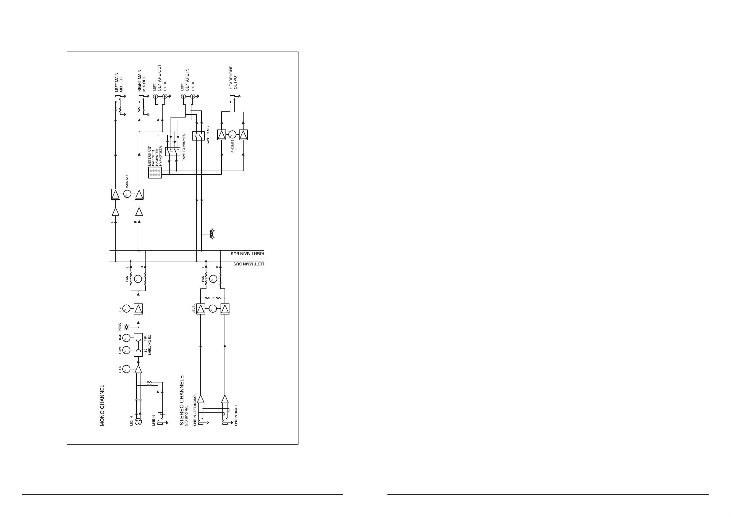
6. BLOCK DIAGRAMM
1. INTRODUCTION
Thank you for expressing your confi dence in our products by buying the LAX5 mixer . The LAX5 is a
compact mixer for professional use. Its smooth, accurate and natural sounding sound characteristics make it ideal for smaller events, recordings or installations.
The LAX5 Mixer is extermely easy to use. We nonetheless advise you to study this manual carefully ,
this way you will get the most out of your LAX5 mixer.
2. FEATURES
The LAX5 mixer provides the following features
- One mono input with XLR and TRS inputs
- Two Stereo inputs with balanced TRS sockets
- A 2-Band EQ for the mono input
- 2 track in- and outputs
- Balanced output with TRS sockets
3. GETTING STARTED
3.1 Please check the AC voltage available in your country before connecting your LAX5 to the AC
socket.
3.2 Be sure that the main power switch is turned off before connecting the mixer to the AC socket.
You should also make sure that all input and output controls are turned down. This will avoid damage to your speakers and avoid excessive noise.
3.3 If you have an amplifi er connected to the main outputs of the LAX5, make sure to fi rst turn on the
LAX5 and then the amplifi er. When fi nished working, fi rst turn off the amplifi er and then the LAX5.
3.4 Before disconnecting the LAX5 always turn-off the power switch.
3.5 Do not use solvents to clean your LAX5. A dry and clean cloth is suffi cient..
LD-Systems
Page 12
LD-Systems
Page 5
Page 6
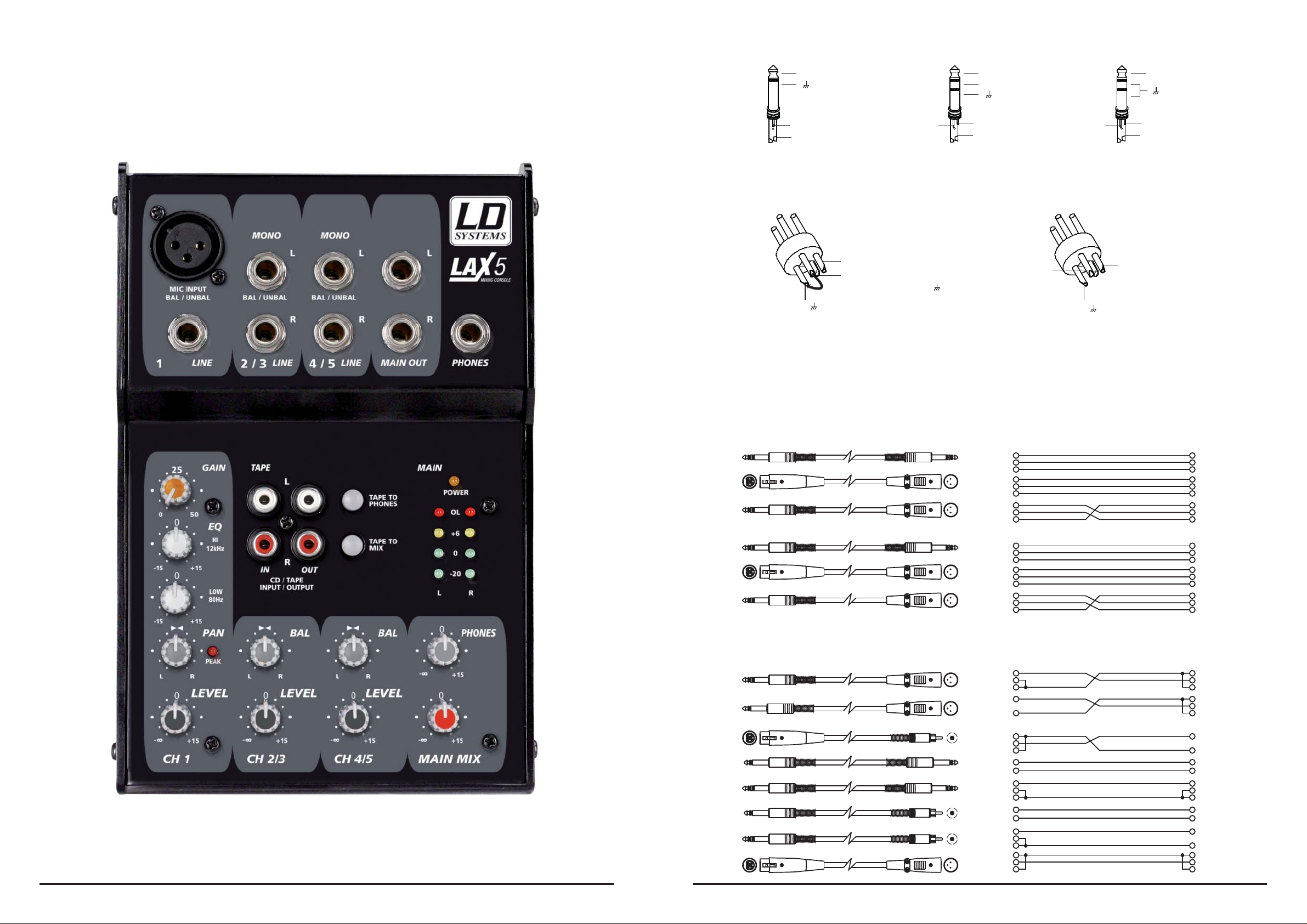
4. CONTROL ELEMENTS - LAX5
- For XLR connector
- In-line Connection
- For 1/4” Phone jack
+
+
+
-
Tip
Sleeve
Ring
Tip
Sleeve
TRS Type Unbalanced
Pin2 (+)
Pin3 (-)
(Linked to Pin1 manually, )
Pin1 ( )
TRS Type Balanced
Pin3 (-)
XLR Type Unbalanced XLR Type alanced B
Ring
TRS Type Unbalanced
Pin1 ( )
Tip
Sleeve
Pin2 (+)
For these applications the unit provides 1/4" TRS and XLR connectors to easily interface with most
professional audio devices. Follow the configuration examples below for your particular connection.
Balanced
TIP RING SLEEVE
1
3
2
TIP RING SLEEVE
TIP RING SLEEVE
1
3
2
TIP RING SLEEVE
Unbalanced
TIP RING SLEEVE
TIP SLEEVE
SLEEVE RING TIP
3
3
SLEEVE RING TIP
3
3
3
3
12
12
12
12
12
12
Ring
Sleeve
Ring
Sleeve
Ring
Sleeve
Ring
Sleeve
Ring
Sleeve
Sleeve
Tip
1
2
3
Tip
Tip
1
2
3
Tip
Tip
Tip
Tip
Ring
Sleeve
1
2
3
1
2
3
Tip
Ring
Sleeve
1
2
3
1
2
3
1
2
3
1
2
3
LD-Systems
Page 6
LD-Systems
3
21
TIP SLEEVE
TIP RING SLEEVE
TIP SLEEVE
TIP RING SLEEVE
3
21
SLEEVE TIP
SLEEVE RING TIP
3
12
Sleeve
Ring
Sleeve
Sleeve
Ring
Sleeve
1
2
3
Tip
Tip
Tip
Tip
1
2
3
Cent er
Screen
Tip
Sleeve
Tip
Ring
Sleeve
Cent er
Screen
Centre
Screen
1
2
3
Page 11
Page 7
5. INSTALLATION AND CONNECTION
Now that you have a rough idea of the mixers functions you should be able to operate it. However,
we strongly recommend you read the following section carefully as it contains a number of useful
tips on how to operate the mixer correctly.
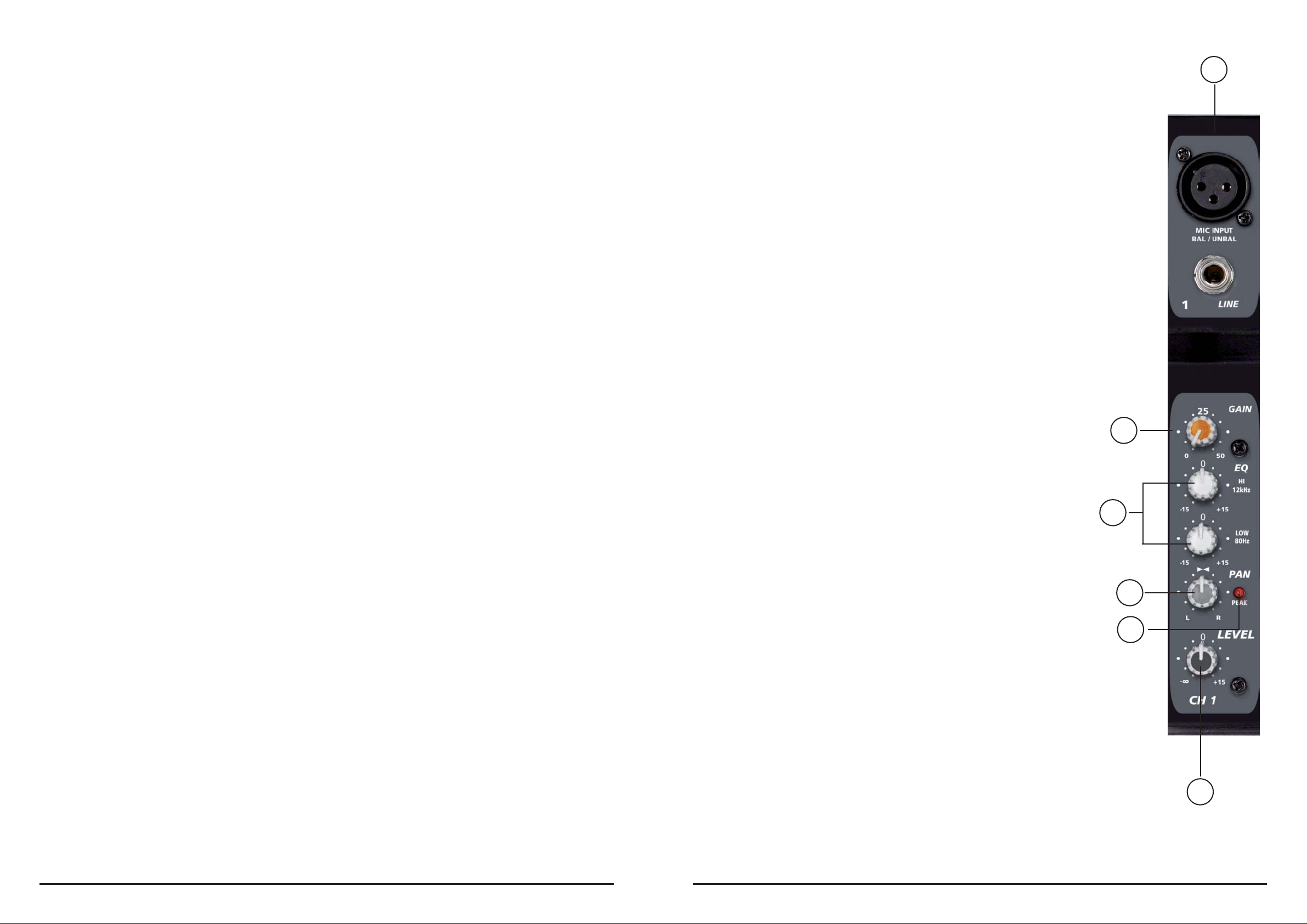
4.1 - THE MONO CHANNEL
You can connect balanced low impedance mirophones or a low
level signal to the XLR socket. On the 1/4” line jack you can connect line level instruments such as drum computers, synthesizers,
effects processors or any other line level devices.
1
- Make sure the input- and master levels of the LAX5 are turned down before you connect microphones and instruments to the inputs.
- Properly connect all external devices such as mics, power amplifi ers, speakers, effects processor
etc.
- Be sure to lay the cables safely to avoid injury or damage to your equipment.
- Set the output level of your mixer or the connected power amplifi er to no more than 75%.
- Set the PHONES level to no more than 50%.
- Position HI and LOW EQ controls on middle position.
- Position the panorama and balance (PAN/BAL) controls in center position.
- While speaking/singing into the mic (or playing the instrument), adjust the channel Level control so
that the channel PEAK LED (in the case of the fi rst channel) will blink occasionally, in this way you
will maintain good headroom and an ideal dynamic range.
- You can shape the tone of each channel by adjusting the equalizer controls as desired.
- Now repeat the same sequence for all other input channels. Keep an eye on the main LED chain
and make sure it does not move up too far into the red section.
Note: It is not possible to use both inputs simultaneously
4.2 - ADJUSTING THE INPUT LEVEL (GAIN)
Adust this level so that the peak LED lights up occasionally, the
peak LED should not be lit constantly, in this case your signal may
be distorted.
4.3 - 2-BAND EQ
The fi rst channel of the mixer is equipped with a simple 2 Band EQ
for adjusting the sound.
HI
This is the Treble control. It can be used to eliminate unwanted high
frequencies or to give your signal mor brilliance and presence. It
ranges from -15dB to +15dB with a center frequency of 12kHz.
LOW
This is the bass control. It can be used to boost a male voice, a kickdrum or a bass guitar. The gain ranges from -15dB to +15dB with a
center frequency at 80Hz.
2
5.1 AUDIO CONNECTIONS
For maximum fl exibility both XLR and 1/4 “ TRS connectors are available on this unit. There are a
number of ways to connect your equipment. Read the following chapter to learn more.
Wiring confi guration
Either the 1/4” TRS phone jack or XLR connectors can be wired in balanced and unbalanced modes,
depending on the equipment used. Please see the following examples on how to wire up your system:
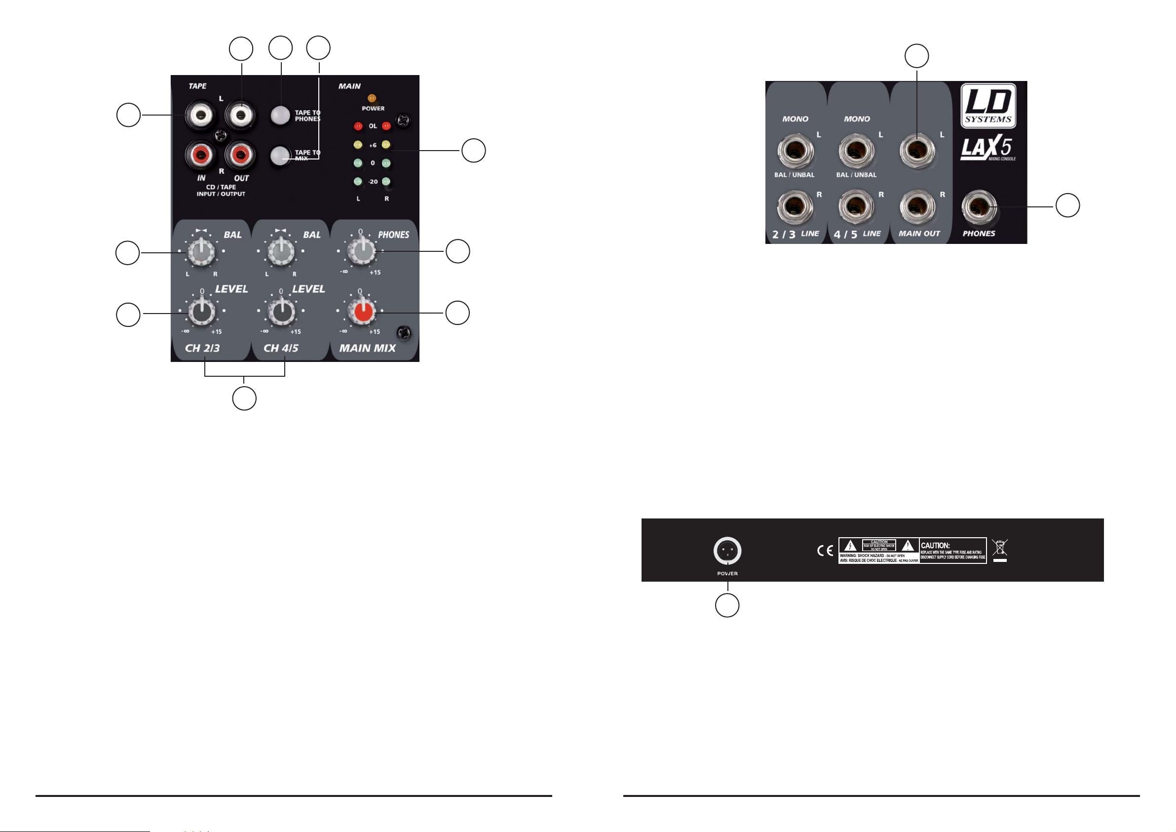
4.4 - PAN / BAL
The fi rst channel of the LAX5 has a PAN control wheras the other
two stereo cahnnels have a balance control. Both controls are used
to to distribute the incomming signal across the left and right channel of the main output.
4.5 - PEAK-LED
The fi rst channel of the LAX5 is equipped with a peak LED. It lights
up, when the signal is about to distort (6 dB below actually distorting). When this LED is lit it means, that the maximal level has been
reached.
4.6 - LEVEL
Here you can adjust the volume of the cannel and consequently the
level of the signal which is passed on to the main mix.
4.7 - THE STEREO CHANNELS
The stereo channels are counfi gured as stereo pairs with TRS jack
inputs. Connect mono signals to the left input.
4.8 - MAIN MIX
Herewith you can adjust the overall level of the signal that is sent to
the main outputs and to the tape output.
3
4
5
6
LD-Systems
Page 10
LD-Systems
Page 7
Page 8
11
12
13 14
16
10
15
4
6
9
8
7
4.9 - PHONES
Here you can adjust the level of the signal sent to the phones output
4.10 - LED-METER
This 4-segment display helps you monitor the overall level of the main mix. The red OL LEDs should
only light up occasionally.
4.11- CD/TAPE INPUT
This unbalanced cinch input can be used to connect a CD player of other stereo devices. You can
route the incomming signal to the main mix or to the headphones.
4.15 PHONES
Connect headphones to this socket in order to monitor the main mix
4.16 MAIN MIX OUTPUT
These are the output connectors for the Main Mix. Connect this output to an amplifi er or active PA
system
4.17 POWER CONNECTION (REAR)
This is the power connector for the LAX5, please only use the supplied adaptor with the LAX5
LAX5
4.12 CD/TAPE OUTPUT
Here you can connect a stereo recording device such as a tape deck in order to record the mix. The
signal is the same as that of the main mix.
4.13 - TAPE TO PHONES SWITCH
Pressing this switch will route the CD/TAPE INPUT signal to the headphones.
4.14 - TAPE TO MIX SWITCH
Pressing this switch will route the CD/TAPE INPUT signal to the Main Mix.
LD-Systems
Page 8
LD-Systems
17
Page 9
 Loading...