

Page 1
Model LPC-19-G & LPC-31-G
GAS CONVEYOR OVEN
INSTALLATION, SERVICE & PARTS MANUAL
POST THIS MANUAL IN A PROMINENT LOCATION ALONG WITH INSTRUCTIONS TO
BE FOLLOWED IN THE EVENT THE USER SMELLS GAS. THIS INFORMATION SHALL BE
OBTAINED BY CONSULTING YOUR LOCAL GAS SUPPLIER.
RETAIN THIS MANUAL FOR FUTURE REFERENCE.
LBC BAKERY EQUIPMENT, INC.
6026 31st Ave NE
Marysville, WA 98271, USA
Phone: 888-RACKOVN (888-722-5686)
Email: service@lbcbakery.com
Website: www.lbcbakery.com REV D 8/2016
Page 2
2
READ FIRST T
READ, UNDERSTAND AND FOLLOW THE INSTRUCTIONS AND WARNINGS CONTAINED IN THIS
MANUAL. IT IS THE RESPONSIBILITY OF THE OWNER/OPERATORS OF THIS APPLIANCE TO TRAIN,
SUPERVISE AND AUTHORIZE ANY PERSON DESIGNATED AS AN OPERATOR. ALL OPERATORS MUST
READ AND UNDERSTAND THIS MANUAL.
Your LBC Conveyor Oven was manufactured to rigid standards. The appliance has been tested and is listed by Intertek
Testing Services (ETL Semko) and meets applicable safety and sanitation standards.
A. The responsibility of the manufacturer is to supply suitable, comprehensive instructions and recommendations for
proper operation and maintenance.
B. All operations, maintenance and repair of this or any appliance must be performed by properly trained and qualified
personnel, and all such operations, maintenance and repair must be performed in a diligent manner. It is the
responsibility of the owner/operator to ensure proper training and diligence of any person coming into contact with
either the subject units or the output (product, fumes or otherwise) of the subject units. It is the responsibility of the
owner/operator to ensure that the subject units are installed and operated in accordance with OSHA Standard
1910.263.
C. A regular periodic program of cleaning, inspection and maintenance must be established and comprehensive
maintenance records maintained. It is the sole responsibility of the owner/operator to establish, schedule and
enforce the frequency and scope of these programs in keeping with recommended practice and with due consideration
given to actual operating conditions.
D. The appliance must be operated within limits which will not exceed its working limits. It is the responsibility of the
user to operate this appliance in accordance with the rules and limits described in this manual and the published
product specification sheet, and in accordance with the directions and instructions of the owner/operator of the
appliance or employer, and in accordance with applicable federal, state and local laws and ordinances.
C A U T I O N
W A R N I N G
DO NOT STORE OR USE GASOLINE
OR OTHER FLAMMABLE VAPORS OR
LIQUIDS IN THE VICINITY OF THIS OR
ANY OTHER APPLIANCE.
D A N G E R
W A R N I N G
IMPROPER INSTALLATION, ADJUSTMENT, SERVICE OR MAINTENANCE
CAN CAUSE PROPERTY DAMAGE,
INJURY OR DEATH. READ THE
INSTALLATION, OPERATING AND
MAINTENANCE INSTRUCTIONS
THOROUGHLY BEFORE INSTALLING
OR SERVICING THIS EQUIPMENT.
C A U T I O N
ALWAYS KEEP THE AREA NEAR
THE APPLIANCE FREE FROM
COMBUSTIBLE MATERIALS.
DO NOT OBSTRUCT FLOW OF COMBUSTION AND VENTILATION AIR.
Page 3

3
TABLE OF CONTENTS T
CHAPTER PAGE
Read First . . . . . . . . . . . . . . . . . . . . . . . . . . . . . . . . . . . . . . . . . . . . . . . . . . . . . . . . . . . . . . . . . . . . . 2
Specifications . . . . . . . . . . . . . . . . . . . . . . . . . . . . . . . . . . . . . . . . . . . . . . . . . . . . . . . . . . . . . . . . . 4
Clearance Requirements . . . . . . . . . . . . . . . . . . . . . . . . . . . . . . . . . . . . . . . . . . . . . . . . . . . . . . . . 5
Conditions of Installation . . . . . . . . . . . . . . . . . . . . . . . . . . . . . . . . . . . . . . . . . . . . . . . . . . . . . . . . . 6
Receiving and Unpacking . . . . . . . . . . . . . . . . . . . . . . . . . . . . . . . . . . . . . . . . . . . . . . . . . . . . . . . . . 6
Installation . . . . . . . . . . . . . . . . . . . . . . . . . . . . . . . . . . . . . . . . . . . . . . . . . . . . . . . . . . . . . . . . . . . . 7
Reversing Conveyor Belt Direction . . . . . . . . . . . . . . . . . . . . . . . . . . . . . . . . . . . . . . . . . . . . . . . . 14
Gas Type Conversion . . . . . . . . . . . . . . . . . . . . . . . . . . . . . . . . . . . . . . . . . . . . . . . . . . . . . . . . . . . . 14
Gas Safety Procedures . . . . . . . . . . . . . . . . . . . . . . . . . . . . . . . . . . . . . . . . . . . . . . . . . . . . . . . . . . 15
Servicing / Preventive Maintenance . . . . . . . . . . . . . . . . . . . . . . . . . . . . . . . . . . . . . . . . . . . . . . . 16
Control Operation . . . . . . . . . . . . . . . . . . . . . . . . . . . . . . . . . . . . . . . . . . . . . . . . . . . . . . . . . . . . . . 17
Parts List . . . . . . . . . . . . . . . . . . . . . . . . . . . . . . . . . . . . . . . . . . . . . . . . . . . . . . . . . . . . . . . . . . . . . 18
Wiring Diagram . . . . . . . . . . . . . . . . . . . . . . . . . . . . . . . . . . . . . . . . . . . . . . . . . . . . . . . . . . . . . . . 26
Warranty . . . . . . . . . . . . . . . . . . . . . . . . . . . . . . . . . . . . . . . . . . . . . . . . . . . . . . . . . . . . . . . . . . . . . 28
Page 4
4
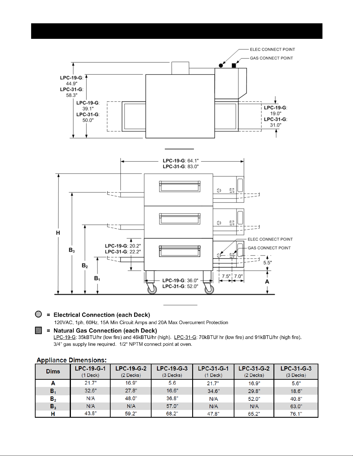
SPECIFICATIONS S
Top View
Front View
Page 5
5
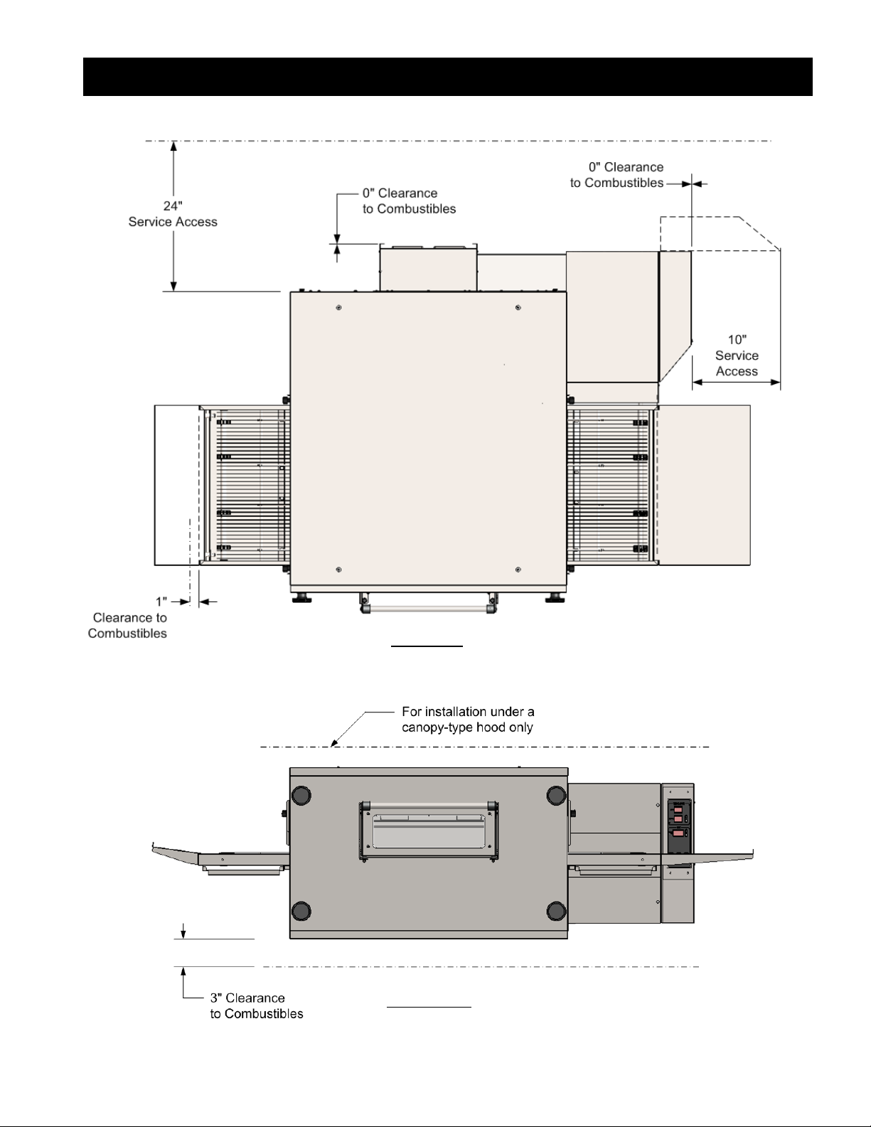
CLEARANCE REQUIREMENTS .
Top View
Front View
Page 6
6
CONDITIONS of INSTALLATION I
LBC Bakery Equipment shall, for a fee contingent on site location and provided that the conditions of installation are met,
provide a factory-authorized service agency to install the LBC Rotisserie. The job site must be ready for installation before
LBC Bakery Equipment or its authorized agent arrives. If the installation site is not properly prepared or if there are
construction delays, the customer shall be responsible for all expenses incurred during this delay. All expenses resulting from
job delay or extension, for reasons beyond the control of LBC Bakery Equipment, shall be the responsibility of the customer.
Installation shall be conducted during normal business hours. This installation is for a single trip. Start-up and training are
not included.
THE INSTALLATION MUST CONFORM WITH LOCAL CODES, OR IN THE ABSENCE OF LOCAL CODES, WITH THE National Fuel
Gas Code, ANSI Z223.1/NFPA 54, OR The National Gas and Propane Installation Code, CSA B149.1, AS APPLICABLE.
It is the responsibility of the owner/operator to do the following:
A. Secure all required permits and meet all local code requirements.
B. Ensure the installation site is cleared and ready for installation before the authorized installer arrives on site. The site
shall be smooth and level.
C. Provide electric & gas utilities within five (5) feet of installation location per specifications provided by LBC Bakery
Equipment
D. Provide licensed trades person to make the final electrical and water connections.
E. Provide adequate ventilation, including vented hoods and associated roof penetrations.
F. Remove all packing materials, crates, etc. resulting from the installation.
G. Provide any sheet metal work required by local codes or otherwise to bridge gaps between appliance and adjacent walls
or other building structures.
RECEIVING and UNPACKING I
Receiving
Upon receiving the appliance, immediately check for damage (both visible and concealed) and loss. Visible damage must be
noted on the freight bill at the time of delivery and signed by the carrier’s agent. Concealed damage or loss means damage
or loss which does not become apparent until the merchandise has been unpacked. If concealed damage or loss is discovered
upon unpacking, make a written request for inspection by the carrier’s agent within 15 days of delivery. All packing material
should be kept for the inspection. DO NOT return damaged merchandise to LBC Bakery Equipment; you must file your claim
with carrier.
Unpacking
Prior to unpacking, move the appliance as near to its intended location as practical. Existing packaging will help protect the
oven from physical damage normally associated with moving it through hallways and doorways. The appliance will arrive
inside a wood frame and affixed to a pallet. Remove the wood frame and strapping bands before lifting the unit from the
pallet and placing in its intended location.
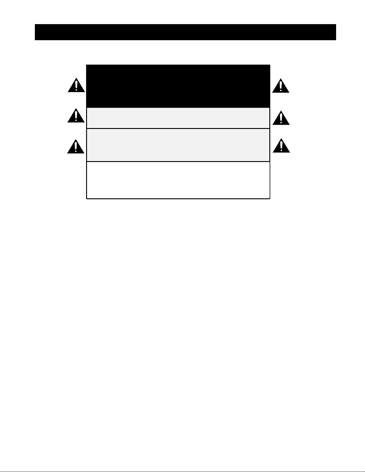
C A U T I O N
SHIPPING STRAPS ARE UNDER TENSION AND CAN
SNAP BACK WHEN CUT.
C A U T I O N
THIS APPLIANCE WEIGHS UP TO 1225 LBS. FOR
SAFE HANDLING, INSTALLER SHOULD OBTAIN
HELP AS NEEDED OR EMPLOY APPROPRIATE
MATERIAL-HANDLING EQUIPMENT (SUCH AS A
FORKLIFT, DOLLY OR PALLET JACK) TO REMOVE
THE UNIT FROM ITS PACKING MATERIALS AND
TO MOVE IT TO THE PLACE OF INSTALLATION.
Page 7
7
INSTALLATION (Part 1 of 8) 0
THE INSTALLATION MUST CONFORM WITH LOCAL CODES, OR IN THE ABSENCE OF LOCAL CODES, WITH THE National Fuel
Gas Code, ANSI Z223.1/NFPA 54, OR The National Gas and Propane Installation Code, CSA B149.1, AS APPLICABLE.
Clearances
Refer to Clearance Requirements section of this manual for spacing from combustible construction and clearances required
for servicing or inspecting components.
Ventilation and Exhaust
VENTILATION AND EXHAUST REQUIREMENTS MUST COMPLY WITH THE NATIONAL FIRE PROTECTION ASSOCIATION
STANDARD, NFPA 96, AS WELL AS ANY AND ALL LOCAL AND STATE CODES.
The conveyor oven must be installed under a ventilation hood. Hood must have adequate overhangs and exhaust rates to
completely capture byproducts of combustion discharged from oven.
C A U T I O N
EACH OVEN MAY WEIGH UP TO 400 LBS. FOR SAFE
HANDLING, INSTALLER SHOULD OBTAIN HELP AS
NEEDED OR EMPLOY APPROPRIATE MATERIALHANDLING EQUIPMENT SUCH AS A FORKLIFT, DOLLY
OR PALLET JACK.
C A U T I O N
ALL ELECTRICAL, MECHANICAL, GAS, VENTILATION
AND EXHAUST CONNECTIONS MUST MEET ALL
FEDERAL, STATE AND LOCAL CODES OR ORDINANCES.
INSTALLATION OF THIS APPLIANCE MUST BE
DONE BY PERSONNEL QUALIFIED TO WORK
WITH ELECTRICITY AND GAS. IMPROPER
INSTALLATION CAN CAUSE INJURY TO
PERSONNEL AND/OR DAMAGE TO
EQUIPMENT.
W A R N I N G
N O T I C E
During the first few hours of operation , you
may notice a small amount of smoke coming
from the rotisserie and /or a faint odor. This is
normal in a new oven and will disappear after a
few hours of use.
Page 8
8
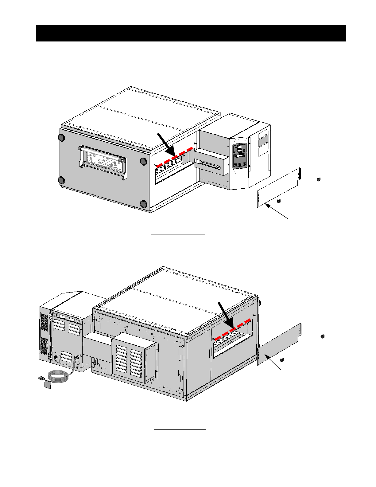
INSTALLATION (Part 2 of 8) 0
Lifting Individual Ovens
Note safe lifting zones indicated by dashed lines on illustrations below. Do not attempt to lift oven by edges not marked
with a dashed line. Refer to these illustrations when moving oven(s) as called out in following installation steps.
Remove
Adjustable
Panel
Remove
Adjustable
Panel
Front View of Oven
Rear View of Oven
Page 9
9
INSTALLATION (Part 3 of 8) 0
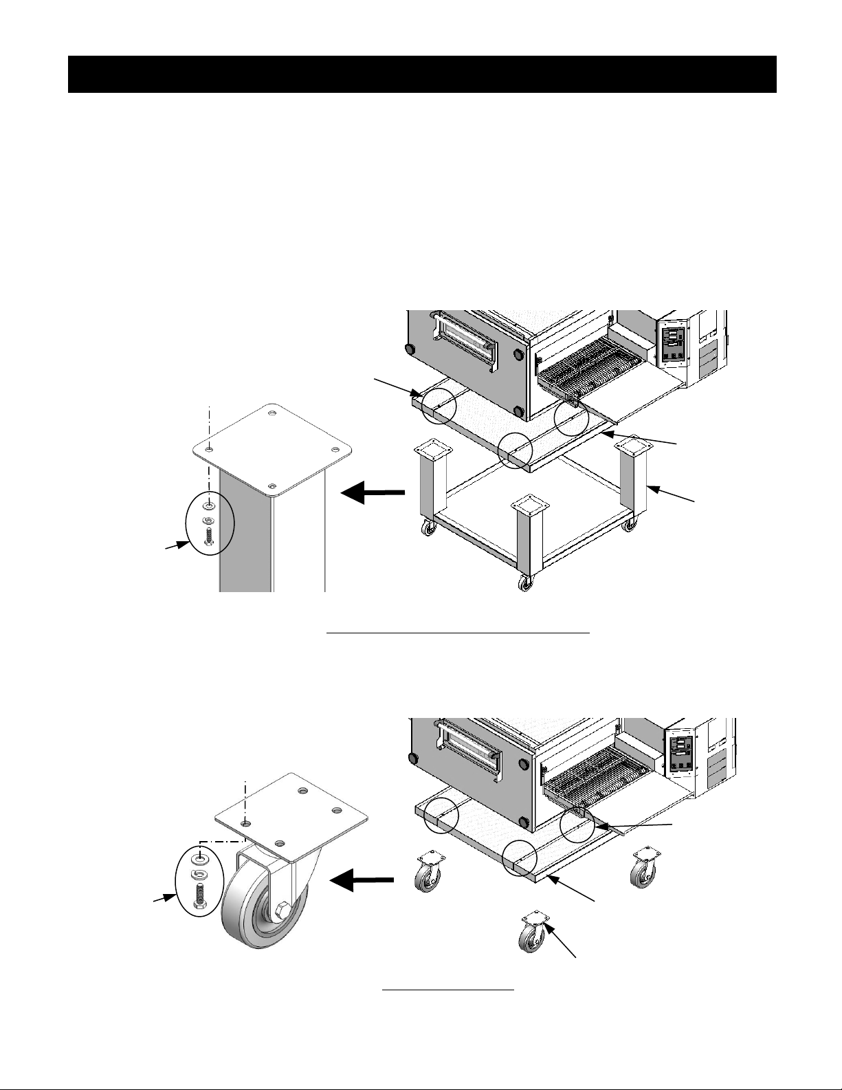
Base and Casters
Depending upon model, appliance will be supplied with either a base with swivel casters or swivel casters only. (Singlestacked and double-stacked ovens are installed on base with casters; triple-stacked ovens are installed on casters only.)
Locate base panel and secure base or casters to underside of it as shown below. Use 16 each M8 X 20mm hex bolts, M8
plain washers and M8 lock washers provided. Once this is done, lift the oven onto the base panel sub-assembly. Remove
oven front panel and rear panel and secure oven to base panel (4 places LPC-19-G, 8 places LPC-31-G) through the oven
cook chamber floor. Use M6 X 20mm long truss head screws, 6mm flat washers and 6mm lock washers provided.
Base
Base Panel
First: Secure
Base to
Base Panel
Base Panel
Caster
Single-Stacked and Double-Stacked Ovens
Triple-Stacked Ovens
Second: Secure Oven
to Base Panel at
circled areas
First: Secure
Casters to
Base Panel
Second: Secure
Oven to Base
Panel at circled
areas
Page 10

10
INSTALLATION (Part 4 of 8) 0
Leveling
Once assembled, move oven to desired location and check level. If oven is not level, loosen bolts at leg or caster mount
plates and shim between plates and underside of oven with washers as needed. Once level, re-tighten hex bolts.
Stacking (For single ovens, skip to next step)
Lift stacked oven onto bottom oven. Place hands only in safe lifting zones as noted previously in this section. Align top
oven bottom flange over bottom oven and gently lower into place. Bottom flange of top oven should slide over bottom
oven as shown below. Repeat this step for triple stacked ovens.
Remove front and rear oven panels of stacked oven(s). Do not remove panels of bottom oven. Locate 4 each holes in
bottom flanged panel of each oven. Secure each pair of ovens together through these holes with 4 each M6 X 20mm truss
head screws, plain washers and lock washers provided.
Install Top Panel
Secure Top Panel to top of top oven. For LPC-19-G, use 4 each M6 X 20mm truss head screws provided. For
LPC-31-G, use 8 each M6 X 50mm truss head screws provided.
Oven
Oven
Oven
Oven
Bottom
Flange
Top Panel
Page 11

11
INSTALLATION (Part 5 of 8) 0
Conveyor Belt Installation
Remove chain cover attached to side of control compartment (see Illustration 1), exposing driver sprocket. From control side
of cook chamber, place end of conveyor belt onto oven opening with pre-installed driven sprocket on belt oriented toward
driver sprocket (Illustration 2) and slide belt assembly into cook chamber until end of conveyor extends through far side oven
opening. Install chain provided between driver sprocket and driven sprocket. Lift and slide conveyor belt into cook chamber
to minimize distance between driver and driven sprockets and loop chain over both sprockets (Illustration 3). Once chain is
correctly engaged on both sprockets, pull belt assembly toward control end of bake chamber until chain is taut and conveyor
frame is properly seated. Lastly, reinstall chain cover.
C A U T I O N
THE CONVEYOR BELT ASSEMBLY IS HEAVY.
FOR SAFE HANDLING, OBTAIN HELP AS
NEEDED OR EMPLOY MATERIAL-HANDLING
EQUIPMENT TO PERFORM THIS STEP.
Chain Cover
Driven
Sprocket
Driver
Sprocket
Illustration 1
Illustration 3
Illustration 2
Belt Assembly Frame
Page 12

12
INSTALLATION (Part 6 of 8) 0
Conveyor Belt Tension Adjustment
Lift conveyor belt and measure distance from belt to top of conveyor frame (Illustration 1). Distance should be between
2” and 3”. To adjust tension, turn belt tension-adjustment knobs at corners of conveyor frame opposite sprocket end
(Illustration 2). NOTE: Conveyor must be cool when adjusting belt.
Illustration 1 Illustration 2
Electrical Connection
APPLIANCE, WHEN INSTALLED, MUST BE ELECTRICALLY GROUNDED IN ACCORDANCE WITH LOCAL CODES, OR IN THE
ABSENCE OF LOCAL CODES, WITH THE National Electric Code, ANSI/NFPA 70, OR The Canadian Electrical Code, CSA C22.2,
AS APPLICABLE.
Connect 120VAC cord(s) to a power source. One cord is supplied for each oven. Cords are 8’ long and connected at backside
of control compartment. For dimensional locations of cord connect points, refer to Specifications section of this manual.
Functional Check (Also refer to Controller Operation section of this manual)
Turn wall breaker on to energize oven and verify:
Oven controller Power button LED is on
Turn oven on at Power button and verify:
All controller displays illuminate
Press Conveyor button to turn conveyor on and verify:
Belt consistently engages center sprockets without slipping off teeth
All adjacent center sprockets engage the same belt link
2
"
3
"
W A R N I N G
THIS APPLIANCE IS EQUIPPED WITH A THREEPRONG (GROUNDING) PLUG FOR YOUR
PROTECTION AGAINST SHOCK HAZARD AND
SHOULD BE PLUGGED DIRECTLY INTO A
PROPERLY GROUNDED THREE-PRONG
RECEPTACLE. DO NOT CUT OR REMOVE THE
GROUNDING PRONG FROM THIS PLUG.
Belt TensionAdjustment
Knobs
Center
Sprockets
Page 13

13
INSTALLATION (Part 7 of 8) 0
Press Fan button to turn fan on and verify:
Heat-circulation fan turns on
Fan button LED illuminates
Gas Connection
INSTALLATION MUST CONFORM WITH LOCAL CODES, OR IN THE ABSENCE OF LOCAL CODES, WITH THE National Fuel Gas
Code, ANSI Z223.1/NFPA 54, OR The National Gas and Propane Installation Code, CSA B149.1, AS APPLICABLE.
Read Emergency Shut-Down section of this manual before proceeding with this stage.
Turn off all electric power to appliance.
Connect gas supply to 1/2”NPTF inlet on gas valve located at right rear of each oven. One flexible gas hose is required for
each gas connect point. The hose(s) must be of sufficient length to allow appliance to be moved for periodic cleaning after
installation. For dimensional locations of connect points, refer to Specifications section. Install a pressure regulator (by
others) before oven gas valve(s). Ensure that pipes are clear of dirt or other obstructions. Verify gas supply type matches gas
type required for appliance. Gas supply line must at least be the equivalent of 3/4” iron pipe. Verify that gas supply pressure
is between 5”and 11”wc. Leak test all joints and fittings with soapy water; do not leak test using an open flame. Before
proceeding to next step, smell around the appliance area for gas. Be sure to smell next to the floor because some gas is
heavier and will settle on the floor. IF YOU SMELL GAS, FOLLOW GAS SAFETY PROCEDURES OF THIS MANUAL AND
APPLIANCE-OWNER’S EMERGENCY SHUT-DOWN PROCEDURE.
Gas Startup
This appliance is equipped with an ignitor which lights the burners automatically. Do not try to light the burner by hand.
Turn burner on. Ensure gas VALVE control switch is set to “ON.” Turn on electric power to appliance. Turn on control and
adjust Set Point to desired temperature. Press fan button to turn burner on. Verify ignition from sight port on burner.
Check O2 (oxygen) and CO (monoxide) levels. To do this, turn conveyor belt off at control and place flue gas analyzer tube
on belt with end of tube inside oven.
Calibrate Oven Temperature, if required. Insert a thermocouple inside the cook chamber and place on the conveyor belt.
Route the probe wire out of the loading door opening and adjust the oven set point to 350oF. Allow the oven to reach the
set point and stabilize for at least 90 minutes. If the thermocouple reading and the controller actual temperature differ by
more than a couple degrees, the control must be calibrated. To begin, make a note of the temperature difference between
the thermocouple and the controller actual temperature, then turn the control power button off an d hold the fan off/on
button for 3 seconds until a value appears in the set point display. Use the set point up or down arrow to add or subtract the
difference in temperature. (EXAMPLE: If the thermocouple is 10o higher than the actual temperature, add 10. If the
thermocouple is 10o lower than the actual temperature, subtract 10.) Turn the control button on and re-check the
thermocouple against the controller actual temperature. Repeat this procedure until the two temperatures match.
Conveyor Inspection
Verify belt speed. Use Conveyor Speed up or down arrow to set time of 05m:00s. Place object on belt at entrance of cook
chamber and, using a watch with a second hand, time how long it takes the object to travel to exit of cook chamber. If time
C A U T I O N
GAS SUPPLY CONNECTIONS AND ANY PIPE
JOINT COMPOUND MUST BE RESISTANT
TO THE ACTION OF PROPANE GASES.
Page 14

14
INSTALLATION (Part 8 of 8) 0
is correct, proceed to next stage. If otherwise, note the difference in actual time verses set time (in seconds) and calibrate
belt speed per the following paragraph.
Reverse belt direction, if required. Belt direction switch can be found at backside of control box. Set to desired position.
Chain Restraint Kit
Secure the appliance to a building structure with a chain restraint. Affix one end of restraint to rear panel of oven. Two holes
must be drilled to affix 2-hole plate located on either end of restraint. A drill bit and mounting hardware are provided in chain
restraint kit.
Final Inspection
Verify the following:
All screws and connections are tight
Gas connections are tight and do not leak
Sandwich door opens and closes easily and remains closed while in vertical position
Fingerprints, dirt and sticker residue have been cleaned from oven
GAS TYPE CONVERSION 0
If required to change from natural gas to LP gas or vice versa, perform the following steps:
Disable power and gas supply to the appliance.
Remove existing gas orifice at the end of the gas supply line and replace with orifice provided. If the appliance is
stacked, remove orifices from each oven. Discard orifices removed during this step.
Enable power and gas supply to the appliance.
Turn the appliance on and allow gas to fire.
Remove high- and low-fire plastic pressure-adjustment caps and plastic pressure-adjustment screws. Do not discard
these parts.
While burner is on, check the valve pressure while in high fire and low fire. Adjust high and low valve pressures to
match the values shown on the oven’s data plate.
Reinstall high- and low-fire plastic caps.
Page 15

15
GAS SAFETY PROCEDURES )
FOR YOUR SAFETY, READ BEFORE OPERATING
A. This appliance is equipped with an ignition device which automatically lights the burner. DO NOT try to light the burner
by hand.
B. BEFORE OPERATING, smell around the appliance for gas. Be sure to smell next to the floor, because some gas is heavier
than air and will settle on the floor.
FOR YOUR SAFETY
WHAT TO DO IF YOU SMELL GAS
Do not light any appliance.
Do not touch any electrical switch.
Do not use any phone in your building.
Immediately call your gas supplier from a phone outside of your building. Follow the gas supplier’s instructions. If
you cannot reach your gas supplier, call the fire department.
To Turn ON Gas to Appliance
1. STOP! Read the safety information above.
2. Ensure external gas valve is set to ON position.
3. Turn on power to appliance and turn on appliance at Power button.
4. Press fan button on control to turn on fan and burner.
5. If appliance begins to heat up, proceed to next step. If appliance does not heat up, turn off power to appliance and wait
five minutes to clear out any gas. If, after five minutes, you smell gas, STOP! Follow safety instructions above. If you do
not smell gas, repeat steps 2 and 3. If appliance does not heat up after three attempts, call your service technician.
6. Set control Set point to desired temperature.
To Turn OFF gas to appliance
1. Turn off appliance at Power button.
2. Turn external gas valve(s) to OFF position.
WARNING
IF YOU DO NOT FOLLOW THESE INSTRUCTIONS
EXACTLY, A FIRE OR EXPLOSION MAY RESULT,
CAUSING PROPERTY DAMAGE, PERSONAL
INJURY OR LOSS OF LIFE.
Page 16

16
SERVICING / PREVENTIVE MAINTENANCE )
SERVICE WORK MUST CONFORM WITH LOCAL CODES, OR IN THE ABSENCE OF LOCAL CODES, WITH THE National Fuel
Gas Code, ANSI Z223.1/NFPA 54, OR The National Gas and Propane Installation Code, CSA B149.1, AS APPLICABLE.
Clearances
Refer to Clearance Requirements section of this manual for spacing from combustible construction and clearances required
for servicing or inspecting components.
Gas Supply
Before servicing, locate gas valve(s) and turn off. If appliance is to be moved for servicing, inspect gas supply line(s). Ensure
connections will not be turned or pulled when appliance is moved. If necessary, disconnect gas line(s) at union nearest to
oven. Reconnect gas line(s) when servicing is complete and after appliance has been returned to originally-installed position.
Turn gas on at valves. Check gas supply connections with soap-water solution to verify that connections are tight and do
not leak.
Electrical
Before servicing, disable power supply to oven. Disconnect plug(s) from electrical outlet(s). If oven has been installed with
a junction-box, disable power at wall breaker and lock-out/tag-out per customer’s procedures. Check all electrical terminal
screws in control compartment and tighten as needed. After servicing is complete and after appliance has been returned
to its originally-installed position, reconnect power and/or turn breaker back on.
Chain Restraint
The oven has been supplied with a chain restraint. If disconnection of restraint is necessary for servicing, reconnect restraint
after servicing is complete and after appliance has been returned to its originally-installed position.
Main Motor
Check main motor cooling vents for accumulations of lint or other debris and clean as required. NOTE: Main motor bearings
are fully enclosed and do not require lubrication.
Cooling Fan
Check cooling fan for accumulations of lint or other debris and clean as required.
D A N G E R
C A U T I O N
THIS APPLIANCE AND ITS INDIVIDUAL SHUTOFF VALVE
MUST BE DISCONNECTED FROM THE GAS SUPPLY
PIPING SYSTEM DURING ANY PRESSURE TESTING OF
THAT SYSTEM AT TEST PRESSURES IN EXCESS OF ½ psi
[3.5 kPa].
C A U T I O N
THIS APPLIANCE MUST BE ISOLATED FROM THE GAS
SUPPLY PIPING SYSTEM BY CLOSING ITS INDIVIDUAL
MANUAL SHUTOFF VALVE DURING ANY PRESSURE
TESTING OF THAT SYSTEM AT TEST PRESSURES EQUAL
TO OR LESS THAN ½ psi [3.5 kPa].
N O T I C E
Service on this or any other LBC appliance must
be performed by qualified personnel. For an
approved service representative in your area,
visit our website at www.lbcbakery.com or call
our factory toll free at 1-888-722-5686.
Page 17

17
CONTROL OPERATION L
N O T I C E
During the first few hours of operation, you may
notice a small amount of smoke and/or a faint
odor coming from the appliance. This is normal
in new equipment and will disappear after a few
hours of use.
Actual Temp Display
This is the actual temp
inside cook chamber.
Conveyor Speed Buttons
Use to change the conveyor
belt speed.
Set Point Buttons
Use to set temp.
Change Temperature Scale
Simultaneously press-andhold both arrows for 3 sec
to change from oF to oC and
back.
Set Point Display
Use Set Point arrows to
set temp. Set temp will
appear in this display.
Conveyor Belt On/Off
Button
Use to turn the conveyor
Conveyor Speed Display
Use Conveyor Speed arrows
to set desired belt speed.
Belt speed will appear in
this display in minutes and
seconds.
Fan On/Off Button
Use to turn the heat
circulation fans on
and off.
Heat On Light
This light illuminates
when heaters are on.
CooL
Cool-Down Feature
On shutdown, if cook
chamber temp is ≥200oF
[93oC], heaters will turn
off while heater fans
continue to run. When
chamber temp drops
below 200oF [93oC], fans
will stop and control will
turn off. “CooL” will
appear in Conveyor Speed
display whenever CoolDown Feature is active.
Page 18

18
PARTS LIST (Part 1 of 8) W
To order any of the optional parts or accessories listed below, visit our website at www.lbcbakery.com. You may also
call our factory toll free at 1-888-722-5686, or email us at service@lbcbakery.com.
N O T I C E
Service on this or any other LBC appliance must
be performed by qualified personnel. For an
approved service representative in your area,
visit our website at www.lbcbakery.com or call
our factory toll free at 1-888-722-5686.
C A U T I O N
USE OF ANY REPLACEMENT PARTS OTHER THAN
THOSE SUPPLIED BY LBC OR THEIR AUTHORIZED
DISTRIBUTORS CAN CAUSE BODILY INJURY TO
THE OPERATOR AND/OR DAMAGE TO THE
APPLIANCE AND WILL VOID ALL WARRANTIES.
BOTH HIGH AND LOW VOLTAGES ARE
PRESENT INSIDE OF THIS APPLIANCE WHEN
THE UNIT IS PLUGGED/WIRED INTO A LIVE
RECEPTACLE. BEFORE REPLACING ANY PARTS,
DISCONNECT THE UNIT FROM THE ELECTRIC
POWER SUPPLY.
W A R N I N G
Main Assembly
Page 19

19
PARTS LIST (Part 2 of 8) W
Forward Control Compartment Parts
Forward Control Compartment Parts (Continued)
Page 20

20
PARTS LIST (Part 3 of 8) W
Main Motor Parts
Heat Circulation Fan
Horizontal Duct Parts
Page 21

21
PARTS LIST (Part 4 of 8) W
Conveyor Parts
* See 89 for complete Conveyor Assembly
Page 22

22
PARTS LIST (Part 5 of 8) W
Rear Control Compartment Parts
Burner Parts
* See 123 for complete Burner Assembly
Page 23

23
PARTS LIST (Part 6 of 8) W
Item No.
Part Description
Quantity
Per Oven
Part No.
Usage
1
Shelf Extender – Entrance (6”)
1
190-189
LPC-19 only
190-189-1
LPC-31 only
2
Knob, Adjustable Door
4
190-372
3
Adjustable Door
2
190-143-3
LPC-19 only
190-143-1
LPC-31 only
4
Shelf Extender – Exit (12”)
1
190-188
LPC-19 only
190-188-1
LPC-31 only
5
Base with Casters
1
190-787
LPC-19, 1-stack only
190-787-1
LPC-19, 2-stack only
190-797
LPC-31, 1-stack only
190-797-1
LPC-31, 2-stack only
6
Caster
4
72901-25
All 3-stacks only
7
Sandwich Door
1
190-777
8
Front Panel
1
190-770
LPC-19 only
190-770-1
LPC-31 only
9
Knob, Front Panel
4
190-778-1
20
Power Cord
1
31110-25
21
Bracket, Control Mount
1
190-145
22
Control Panel + Control Label
1
190-153 + 190-154
23
Main Control
1
40102-79
30
Tube – Air Switch
1
190-159
LPC-19 only
190-159-1
LPC-31 only
31
Pressure Switch
1
30808-05
32
High Limit
1
30401-33
33
Axial Fan
1
30200-45
34
Flexible Hose - Gas
1
74000-53
35
Gas Valve
1
80505-17
36
Motor, Belt
1
30200-70
37
Gear Reducer
1
30200-78
50
Rear Panel
1
190-761-1
LPC-19 only
190-761-3
LPC-31 only
51
Angle – Motor Mount
2
190-315
LPC-19 only
190-315-2
LPC-31 only
52
Left Side, Motor Cover
1
190-339
LPC-19 only
190-339-4
LPC-31 only
53
Body, Motor Cover
1
190-338
LPC-19 only
190-338-2
LPC-31 only
54
Right Side, Motor Cover
1
190-339-1
LPC-19 only
190-339-3
LPC-31 only
55
Cover, Wireway
1
190-368
LPC-19 only
190-368-2
LPC-31 only
Page 24

24
PARTS LIST (Part 7 of 8) W
Item No.
Part Description
Quantity
Per Oven
Part No.
Usage
56
Motor – 3/4 hp
1
30200-84
LPC-19 only
Motor – 1 hp
30200-85
LPC-31 only
57
Band, Motor
1
71700-03
58
Body, Motor Mount
1
190-316
LPC-19 only
190-316-1
LPC-31 only
60
Fan, Heat Circulation
1
71500-16
LPC-19 only
71500-17
LPC-31 only
70
Body, Upper Duct
2
190-324
LPC-19 only
190-415
LPC-31 only
71
Plate, Duct
5
190-232-2
LPC-19 only
190-414
LPC-31 only
73
Body, Lower Duct
3
190-325
LPC-19 only
190-416
LPC-31 only
80
Knob, Belt Tensioner
2
190-297
81
Belt Tensioner
2
190-743
82
Sprocket, Belt
8
SP636-80-1
LPC-19 only
10
SP636-80-1
LPC-31 only
83
Shaft, Conveyor
1
SP636-70-3
LPC-19 only
SP636-70-4
190-267
LPC-31 only
190-268
84
Sprocket, Drive
1
73000-07
85a
Chain
1
73100-08
85b
Connecting Link for item 85a
1
73100-07
86
Sprocket, Driven
1
SP636-80-5
87
Belt, Conveyor
1
SP636-70-6
LPC-19 only
SP636-70-7
LPC-31 only
88
Crumb Tray
2
190-180-70-15
LPC-19 only
190-263
LPC-31 only
89
Conveyor Belt Assembly
1
190-180-70
LPC-19 only
190-1780-70-1
LPC-31 only
100
Ignition Module
1
80300-23
101
Transformer
1
31400-26
102
Relay
1
30701-05
Page 25

25
PARTS LIST (Part 8 of 8) W
Item No.
Part Description
Quantity
Per Oven
Part No.
Usage
103
Ground Connector
1
31200-08
104
Power Distribution Block
1
30500-01
105
Cover, Control Compartment - Rear
1
190-354
106
Switch, Belt Direction
1
30303-06
120
Flame Sensor Rod
1
41100-36-1
121
Hot Surface Ignitor
1
80302-12
122
Shutter, Air – Burner
1
190-330-1
123
Burner Assembly
1
190-764
LPC-19 only
190-764-3
LPC-31 only
Page 26

26
WIRING DIAGRAM (Part 1 of 2) W
Wiring diagrams are also located on the inside of the control compartment cover.
Page 27

27
WIRING DIAGRAM (Part 2 of 2) W
Wiring diagrams are also located on the inside of the control compartment cover.
Page 28

28
 Loading...