

Page 1
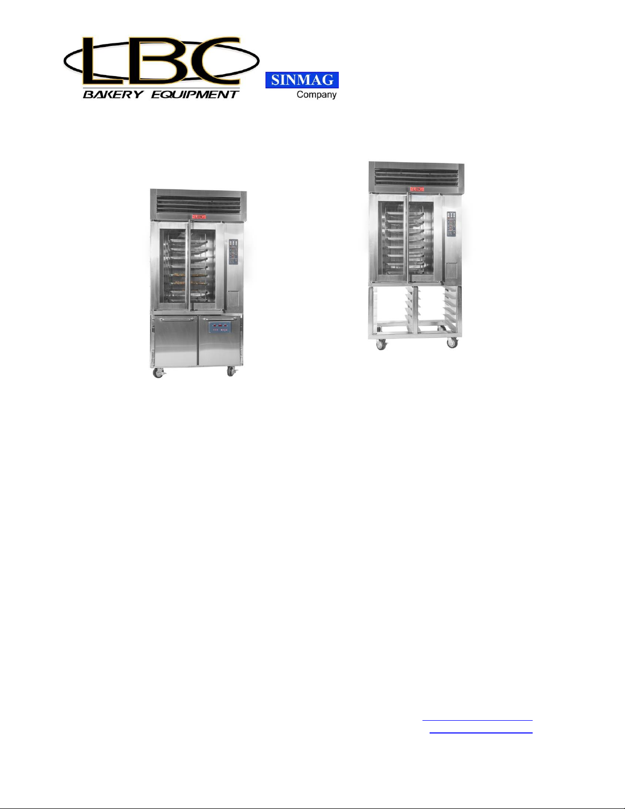
Installation, Operations and Maintenance Manual for LBC Models LMO-G and
LMO-E gas and electric “Mini” Rotating Rack Ovens
Rev.013 July 2013
LBC Bakery Equipment, Inc.
5901 23rd Drive West
Suite 105
Everett, WA 98203
Toll Free: 888-722-5686
Fax: 425-642-8305
E-mail; sales@lbcbakery.com
www.lbcbakery.com
LBC Bakery Equipment, Inc. 1
Page 2

IMPORTANT FOR YOUR SAFETY
WARNING: IMPROPER INSTALLATION, ADJUSTMENT,
ALTERATION, SERVICE OR MAINTENANCE CAN CAUSE PROPERTY
DAMAGE, INJURY OR DEATH. READ THE INSTRUCTION,
OPERATING AND MAINTENANCE INSTRUCTONS THOROUGHLY
BEFORE INSTALLING OR SERVICE THIS EQUIPMENT.
THIS MANUAL HAS BEEN PREPARED FOR PERSONNEL
QUALIFIED TO INSTALL GAS EQUIPMENT, WHO SHOULD
PERFORM THE INITIAL FIELD START-UP AND ADJUSTMENTS OF
THE EQUIPMENT COVERED BY THIS MANUAL
POST IN A PROMINENT LOCATION, THE INSTRUCTIONS TO BE
FOLLOWED IN THE EVENT THE SMELL OF GAS IS DETECTED.
THIS INFORMATION CAN BE OBTAINED FROM THE LOCAL GAS
SUPPLIER
IMPORTANT
IN THE EVENT A GAS ODOR IS DETECTED, SHUT DOWN UNIT AT
MAIN SHUTOFF VALVE AND CONTACT THE LOCAL GAS
COMPANY OR GAS SUPPLIER FOR SERVICE
FOR YOUR SAFETY
DO NOT STORE OR USE GASOLINE OR OTHER FLAMMABLE VAPORS
OR LIQUIDS IN THE VICINITY OF THIS OR ANY OTHER APPLIANCE
IN THE EVENT OF A POWER FAILURE, DO NOT ATTEMPT TO
OPERATE THIS DEVICE.
KEEP AREA AROUND THE OVEN CLEAR OF COMBUSTIBLES. DO
NOT OBSTRUCT COMBUSTION AND VENTILATION OPENINGS
ON THE OVEN.
Keep this manual for future reference.
Electrical schematic is located behind the side access cover.
LBC Bakery Equipment, Inc. 2
Page 3

Lighting Instructions
After Long-term shut-down:
1. Turn on the gas supply to the oven.
2. Lift the gas valve access door located below the control
panel. Switch the gas valve “ON.”
Daily use:
3. Press the “Power” button to turn the oven on. Close the
oven door.
4. Set the oven temperature to the desired operating
temperature by pressing the up or down arrow buttons
next to the “Set Temperature” display.
Shut-Down Instructions
Daily Use:
1. Press the “Power” button to turn the oven off.
Long-term shut-down:
2. Lift the gas valve access door located below the control
panel. Switch the gas valve to “OFF.”
3. Turn off the gas supply to the oven.
LBC Bakery Equipment, Inc. 3
Page 4

Table of Contents
Page 5 Inspect and Uncrate
Installation Codes
Model Designations
Page 6 Utility Connection Points
Page 7 Installation
Install Caster
Installation location
Page 8 1: Gas Connections – Propane/Natural gas conversion
2: Venting
Page 9 Venting Illustration
Safety Considerations
Page 10 3: Plumbing Connections
Water Supply
Drain Connections
4: Electrical Connections
Gas Models
Electric Models
Page 11 Electrical Connection Illustration
Page 12 Shutter Settings
Page 13-14 Installation and Start-up Procedures
Page15 Controls Operation
Page16-20 Wiring Diagrams
Page 21-28 Illustrated Parts List
Page 29 Standard Warranty
Page 30-32 Intentionally Blank
LBC Bakery Equipment, Inc. 4
Page 5

Installation of this equipment must be
performed by an authorized service
representative. Prior to installation
verify that all electrical and gas
supplies coincide with the
manufacturers data label located on
the right side below the service panel.
Inspection and Un-crating
Upon receipt of shipments, all
packages should be inspected, and all
visible or concealed damages noted
and signed for on the bill of lading.
Any other damages should be reported
to the carrier within 10 days. Freight
damages are the responsibility of the
consignee.
All orders for replacement products
resulting in freight damages will be
processed under LBC’s standard terms.
Any reimbursement or credit is the
responsibility of the freight carrier
Carefully unpack the oven and place it
in a work area as near to the final
installation position as possible.
The LMO oven ships with the following
items please inspect your shipment to
ensure that these items were included.
LMO Oven Rack
Decorative hood front, sides
and back pieces
If moving the oven trough a 36” door
opening it will be necessary to remove
the oven door, door latch, door hinges
decorative valance and the rear panel.
Location
This appliance is not intended for
outdoor use. This appliance is not
appliance is intended for commercial
use in locations suitable for use as
listed in this manual.
Clearances to combustible and none
combustible construction:
0” back, sides and top.
This appliance is suitable for
installation on combustible floors.
Installation Codes
For US Installation
The LMO oven must be installed in
accordance with all State and local
codes and:
National Fuel Gas Code, ANSI-Z2231/NFPA 54 (latest edition)
National Electrical Code, ANSI/NFPA70 (latest edition)
For Canadian installation
The LMO oven must be installed in
accordance with all local codes and;
CAN/CGA-B149.1 National Gas
Installation Code
The appliance and its individual shutoff
valve must be disconnected form the
gas supply piping system during any
pressure testing of that system at
pressures in excess of ½ psi (3.5kPa).
The appliance must be isolated from
gas supply piping system by closing its
individual manual shutoff valve during
any pressure testing of the gas supply
piping system at test pressures equal
to or less than ½ psi (3.5 kPa).
intended for residential use. This
Note: The decorative trim is not intended for use as an exhaust hood.
Model Number Coding LMO followed by G (gas models) or E (electric model)
followed by followed by N (for natural gas) or LP for (Propane gas) or 208, 240 or
480 (for electric models) followed by 6 (6-pan rack) 0r 8 (8-pan rack) followed by S
(for stand) or P (for proofer base)
Sample Model Number: LMO-E8-480-P: This is a 480 Volt electric oven with an 8
pan rack and a proofer base.
LBC Bakery Equipment, Inc. 5
Page 6
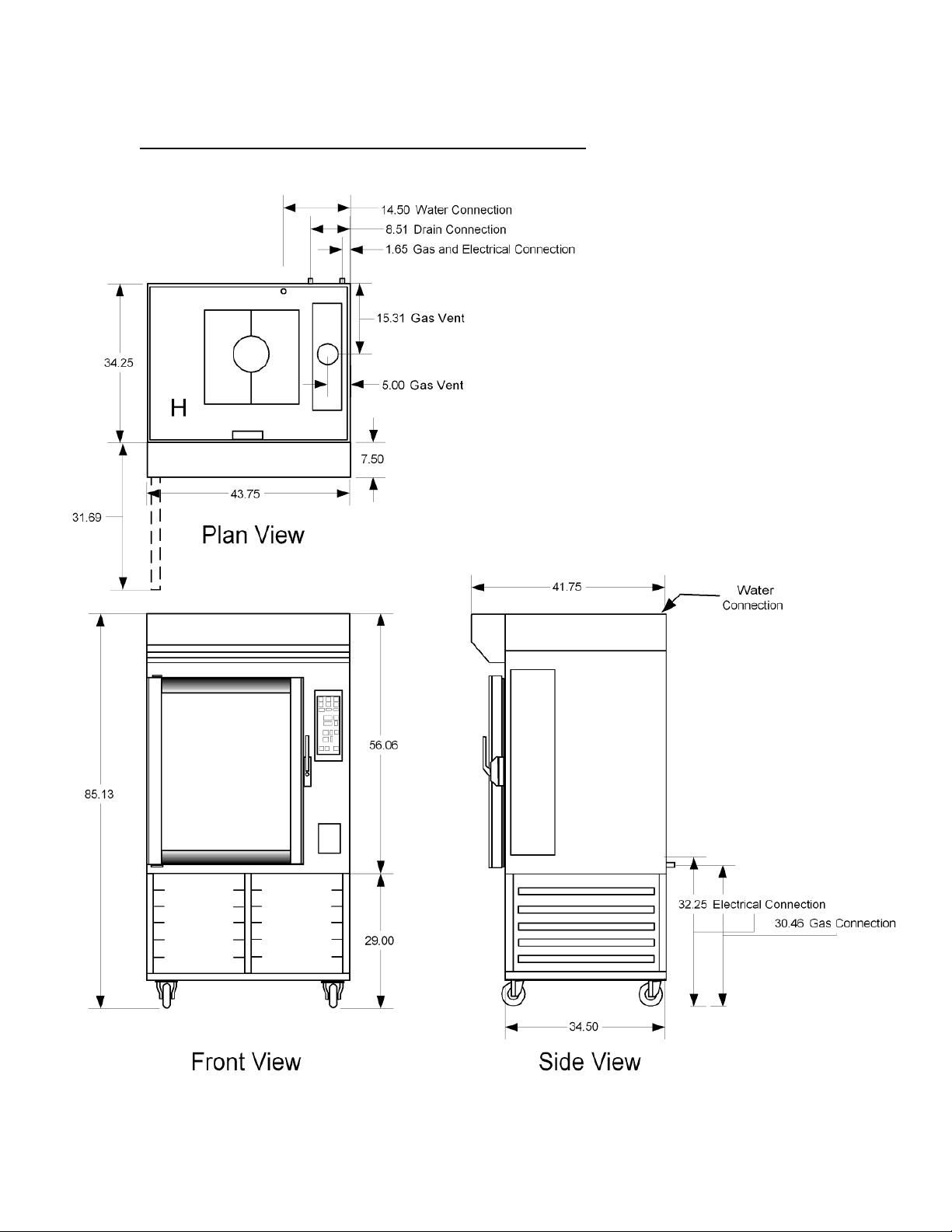
Utility Connection Points and Dimensional Drawing
LBC Bakery Equipment, Inc. 6
Page 7
Installation
Pick Points: Use adequate
material handling equipment to lift
the oven into place, oven weight is
1,100 lbs.
The LMO oven must be installed on the ovens stand using the supplied fasteners or installed
on any non-combustible surface adequate to support the weight of the appliance.
Ovens shipped with a stand must have the casters installed.
With the oven still on the shipping pallet slide the oven and stand forward and install the two
front locking casters.
Move the oven and stand forward onto a pallet truck, lift the oven and stand off of the pallet
and install the two rear casters.
IMPORTANT:
Gas ovens can not be mounted directly to a solid surface as the combustion air intake is from
the bottom side of the oven.
ALL GAS MODELS MUST BE MOUNTED ON OVEN STAND OR PROOFER BASE
Secure the oven to the stand or proofer base with the supplied self-tapping fasteners.
Gas ovens mounted on the oven stand with casters must utilize the following…
A connector that complies with the Standard for Connectors for Movable Gas Appliances, ANZI
Z21.69
Or Connectors for Movable Gas Appliances, CAN/CGA-6.16
A quick disconnect device that complies with the Standard for Quick-Disconnect Devices for
Use With Gas Fuel, ANZI Z21.41
Or Quick Disconnect Devices for Use with Gas Fuel, CAN1-6.9
Adequate means must be provided to limit the movement of the appliance.
Select a location that has a smooth level surface and has adequate room to operate the
appliance (see Illustration – 1 for oven dimensions and utility connection points)
Ensure that the oven is installed on a level surface. If the unit is mounted on the movable
oven stand, loosen the caster bolt and place shims under the base until level, re-tighten the
caster bolts.
LBC Bakery Equipment, Inc. 7
Page 8

1: Gas Connections
CAUTION: Gas supply connections and any
pipe joint compound must be resistant to the
action of propane gases.
The LMO-G is an indirect gas fired oven
consisting of a heat exchanger that consists of
15 (fifteen) in-shot burners and tubes totaling
90,000 BTU/HR.
Verify that the gas supply matched the type
listed on the data label. If the incoming
pressure exceeds ½ psig (3.45kPa) 14” W.C.
install a pressure regulator before the oven’s
gas valve.
Codes require installation of a gas shutoff
valve in the gas line ahead of the oven. The
gas supply line must be at least the equivalent
of ¾” iron pipe. Corrugated lines should not
be used.
Connect the gas supply line to the ¾” NPT
incoming gas connection located at the rear of
the oven. Ensure that the pipes are free and
clear of any dirt or obstruction. If the oven is
supplied with a flexible gas line, secure it to
the oven and wall per the manufacturers
instructions.
2: Ventilation
Ventilation requirements vary with each
installation and must comply with applicable
portions of the National Fire Protection
Association Standard 96 as well as any and
all State and local codes.
Exhaust Fan Interlock
A connection point (5 AMPS Max.) is provided
for indirect vent (Exhaust Hood) or optional
direct vent (Draft Hood). It is located in the
electrical connection box at the right rear
side of the oven. Consult local codes for vent
interlock requirements.
Indirect Vent (Installed under an
exhaust hood) – Standard installation
configuration.
Locate the oven under an exhaust hood with
adequate overhangs and exhaust rates to
completely capture the byproducts of
combustion discharged from the flue. From
Verify that the line pressure before the gas
valves stays between 5” and 14” W.C. for
natural gas or 11” and 14” for W.C. for
propane gas – both with and without the
burner firing.
For conversion to Propane Gas or to
Natural Gas:
1. Shut off the gas supply to the oven.
Remove the bottom burner cover and the
side access cover.
2. Disconnect the gas line at the top of the
gas valve. Remove the four extended
nuts at the bottom of the turner
assembly. Lower the burner out of the
oven.
3. Remove the 15 orifices and replace with
the orifices listed on the burner/heat
exchanger parts list in this manual. Use
approved Teflon tape to seal the orifices.
4. Replace the burner. Reconnect the gas
line, replace the covers. Check for leaks.
5. Operate the burner. Adjust the gas
pressure to the correct pressure listed in
the burner/heat exchanger parts list in
this manual.
6. Apply proper labeling to indicate the
correct gas and pressure on the data plate
and at the gas connection point.
the termination of the flue to the filters of the
hood venting system a clearance of 18” must
be maintained. The exhaust hood fan can be
directly interlocked to the oven (consult the
wiring diagram for terminal location*).
Direct Vent (Draft Hood) – Optional
configuration
Move the oven into position and attached the
customer supplied exhaust ducting and draft
diverter.
Verify that the air is being drawn into the
bottom of the draft diverter while the burner
is firing, using a draft gauge or smoke test.
Using a draft gauge, verify that a draft of
between 0.03” – 0.11” W.C. is maintained at
a point 6” above the draft diverter’s upper
collar. Any exhaust fan or draft inducer used
to maintain system suction must be operating
when the oven is turned on. (See exhaust fan
interlock.)
LBC Bakery Equipment, Inc. 8
Page 9
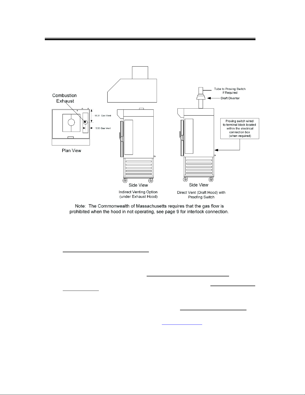
Sample Installation
SAFETY CONSIDERATIONS:
Your LBC BAKERY oven was manufactured to rigid standards. The oven is ETL listed as a unit,
and meets applicable safety standards.
A) The responsibility of the manufacturer is to supply suitable, comprehensive instructions and
recommendations for the operation and maintenance of the subject units.
B) All operations, maintenance and repair of the subject units must be performed by properly
trained and qualified personnel, and all such operations, maintenance and repair must be
performed in a diligent manner. It is the responsibility of the owner/operator to insure
proper training and diligence of any person coming into contact with either the subject units or
the output (product, exhaust or otherwise) of the subject units. It is the responsibility of the
owner/operator to ensure that the subject units are installed and operated in accordance with
OSHA Standard 1910.263.
C) A regular periodic program of cleaning, inspection and maintenance must be established and
comprehensive maintenance records maintained. It is the sole responsibility of the user to
establish, schedule and enforce the frequency and scope of these programs in keeping with
recommended practice and with due consideration given to actual operating conditions. For
suggested cleaning schedule visit our Website @ www.lbcbakery.com First click on Manuals, then
click on Equipment Cleaning under Operation and Programming Manuals, or call LBC @ 1-888722-5686 to have one faxed.
D) The units must be operated within limits, which will not exceed the working limits of any
component.
LBC Bakery Equipment, Inc. 9
Page 10

Volts
Phase
Kw
Amps
Max
Breaker
Min
Circuit
L1
L2
L3
208
3
12.5
39
26
39
60
50
240
3
12.5
30
30
30
50
40
480
3
12.5
15
15
15
30
20
3: Plumbing Connections
WARNING: PLUMBING CONNECTIONS
MUST COMPLY WITH APPLICABLE
SANITARY, SAFETY AND PLUMBING
CODES.
Water Supply
Oven water supply should have a hardness
of 4-6 grains per gallon, pH of 6.5 to 8.0
and chlorides of less than 30 PPM. Water
conditions outside of these parameters
may void the warranty. Please consult
your local water company and or water
condition dealer before installing the ovens
water supply.
4: Electrical Connections
WARNING: ELECTRICAL AND
GROUNDING CONNECTIONS MUST
COMPLY WITH THE APPLICABLE PORTIONS
OF THE NATIONAL ELECTRICAL CODE AND
ALL STATE AND LOCAL CODES.
WARNING: DO NOT CONNECT THE LMOG GAS MODEL OVEN TO ELECTRICAL
SUPPLY UNTIL AFTER GAS CONNECTIONS
HAVE BEEN MADE
Connect the cold water supply to the ½”
NPT fitting located at the rear of the oven
with a 6’-00” flexible water line.
Drain Connections
Connect a ½” drain line to the ½” NPT
drain connector located at the rear of the
oven. Route the drain line to a floor drain
allowing a minimum 1” air gap between
the drain line outlet and the floor drain.
If the oven is being used with a proofer
insert it is recommended that separate
drain and water lines are provided.
LMO-G Gas Models
A 6-ft power supply cord is supplied; it
requires a dedicated 20-Amp110/120 volt
60 Hz single phase supply with ground.
LMO-E Electrical Models
All electric models require a 110/120 volt
60 Hz 20 Amp power supply as well as one
of the following supplies.
Ensure that the electrical supply matched
the voltage listed on the ovens data label.
Attention: This appliance, when installed, must be electrically grounded in
accordance with local codes, or in the absence of local codes, with National Electrical
Code, ANSI/NFPA 70 or the Canadian Electrical Code, CSA C22.2, as applicable.
LBC Bakery Equipment, Inc. 10
Page 11

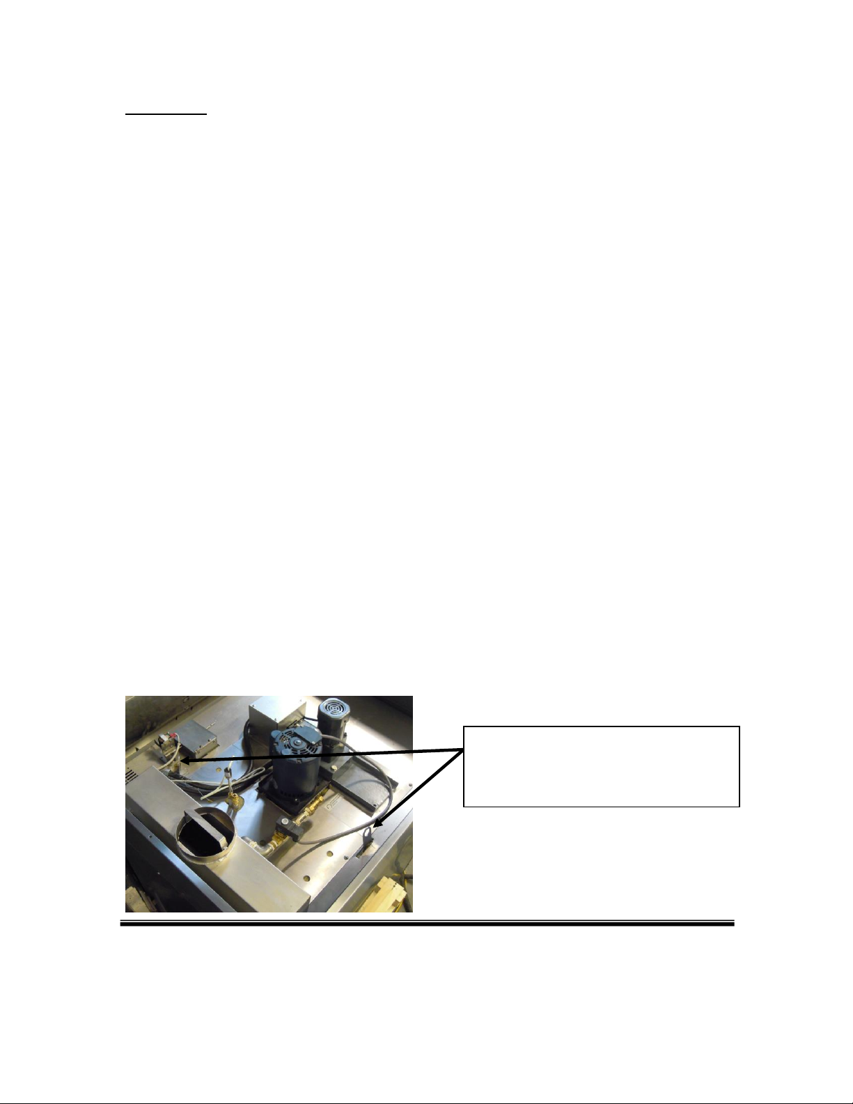
Route the electrical supply through the knock-out at the rear of the oven.
Connect the supply voltage to the terminal block located within the electrical control
compartment at the right rear side of the oven (see the illustrations below).
LBC Bakery Equipment Inc. 10
Page 12

LBC Bakery Equipment Inc. 11
Page 13

Model
Procedure
Standard or Specification
All
Ventilation Requirements
Ventilation requirements will vary with each
installation and must comply with applicable
portions of the NFPA Standard 96
All
Indirect Venting (installation under a hood)
Requires adequate overhang and exhaust
rates to capture byproducts of combustion.
Requires 18" clearance from the top of the
oven flue to the underside of the hood filters
Vapor Removal from Cooking Equipment,
NFPA No. 96
Gas
Direct Venting (Draft Hood)
Direct vent using 6" "B" vent.
All
Exhaust fan interlock
A connection point (5 amps max.) is provided
for indirect or direct vent. It is located within
the rear electrical compartment (terminal TB1).
Consult local codes for vent interlock
requirements
All
Verify supply voltage matched data plate
120
V
208 V
240 V
480 V
1 PH
1PH
3PH
1PH
3PH
1PH
3PH
All
Ensure oven is level
If mounted on a stand with casters, loosen
caster bolts and shim base plate with washers
as necessary to level oven, re-tighten bolts.
All
Seal oven to stand
If oven is installed on a stand it must be sealed
in place using an NSF approved sealant
All
Clearances for operation, to combustibles and
hood clearances
Front
Allow adequate room to operate appliance
Bottom Gas Oven
Gas ovens must be mounted on the oven
stand or on 6" legs. Combustion air is supplied
from the underside of the oven. Never block
the underside of the oven
Sides
Back
Top
0"
0"
18"
Installation and start-up procedures and check list
LBC Bakery Equipment Inc. 12
Page 14

Model
Procedure
Standard or Specification
Gas
Only
Connect oven to gas supply
Connectors in accordance with the Standard for Movable
Gas Appliances ANZI Z21.69 or CAN/CGA-6.16; QuickDisconnect Devices for Use With Gas Fuel, ANZI Z21.41
or CAN1-6.9
Manual gas shut-off valve is required in line ahead of the
oven.
If Required, verify pressure regulator is installed
If incoming pressure is greater than 1/2" psig 14" W.C
If gas oven is on a stand with casters ensure
that the oven has approved restraints
Adequate means must be used to limit the movement of
the appliance
All
Connect oven to water supply
Flexible Lines are acceptable
All
Connect drain line
1/2" Vented Copper Lines
All
Check all connections for leaks
Use soapy water to inspect for leaks
Gas
Only
Connect amp meter to incoming power supply
120 Volts 7 Amp.
Electric
Only
Check Amp Draw Per Line
208 V 3PH
240 V 3PH
480 V 3PH
L1
L2
L3
L1
L2
L3
L1
L2
L3
39
26
39
30
30
30
15
15
15
Gas
Connect manometer to supply side of regulator
verify incoming pressure
Natural Gas
Liquid Propane
Between 5" 14"W.C At All
Times
Between 11" - 14" W.C. At All
Times
All
Press the ON/OFF key at the controls
Interior oven lights come on, rack begins to rotate and
convection blower starts
Set control temperature at 400 Degrees F and allow
oven to complete two full cycles
Verify amperage draw and or gas pressure readings.
All
Open the oven door and ensure the rack stops
at the center of the door opening
If necessary, adjust rotation cam located at the top of the
oven to set the rack stop position
All
Enter a bake time of 30 minutes and a steam
time of 15 seconds
Verify that the oven produces steam, during the steam
time the convection blower stops operating.
Verify that the drain is free and clear
Verify that there are no water leaks
All
Press the Vent key until the open LED is
illuminated
Verify that the vent opens freely
All
Set the bake time for 15-20 minutes with NO
STEAM time and the vent CLOSED
Load parchment covered 18" x 26" sheet pans with
frozen sugar cookie dough placed 3 x 3
Fill every pan slide with a loaded sheet pan
All
Inspect bake for evenness
Adjust shutter apertures and angle as necessary to
achieve an even bake.
LBC Bakery Equipment Inc. 13
Page 15

LBC Bakery Equipment Inc. 14
Page 16

LBC Bakery Equipment Inc. 15
Page 17

LBC Bakery Equipment Inc. 16
Page 18

LBC Bakery Equipment Inc. 17
Page 19

Wiring Diagram:
LBC Bakery Equipment Inc. 18
Page 20

LBC Bakery Equipment Inc. 19
Page 21

Oven Chamber Vent and
PN: 30401-28 Solenoid
Thermocouple PN: 41100-42 and
High Limit Well.
High Limit PN: 30401-28
Unison Opening Doors: Turnbuckle Assembly and Magnetic Door Switch Assembly.
LBC Bakery Equipment Inc. 20
Page 22

LBC Bakery Equipment Inc. 21
Page 23

LBC Bakery Equipment Inc. 22
Page 24

LBC Bakery Equipment Inc. 23
Page 25

LBC Bakery Equipment Inc. 24
Page 26

LBC Bakery Equipment Inc. 25
Page 27

LBC Bakery Equipment Inc. 26
Page 28

LBC Bakery Equipment Inc. 27
Page 29

LBC Limited Warranty
LBC Bakery Equipment (“LBC Equipment”) has been skillfully manufactured, carefully
inspected and packaged to meet rigid standards of excellence. LBC Bakery Equipment
Company (LBC) warrants products produced and sold by LBC and its duly authorized agents,
against defects in materials and workmanship within the following limitations:
What is provided:
Limited replacement parts as specified below,
including standard ground shipping from LBC
or service parts center when required.
Limited labor for repair as specified below,
including authorized service agent’s
transportation, portal to portal, up to one
hundred (100) miles round trip and two (2)
hours travel time.
LBC, or an authorized service representative,
will repair or replace, at LBC’s sole discretion,
any LBC equipment, including but not limited
to the listed exclusions.
Coverage Period:
Extending from the date of shipment from LBC or
its duly authorized dealer/distributor for the
specified period.
LRO and LMO Model Rack Ovens, LRP Model
Rack Proofers and LRPR Model Retarder
Proofers for a period of one (1) year limited
parts and labor.
Replacement parts shall be warranted for a
period of ninety (90) days after installation by
an authorized LBC service agent.
Conditions:
Covered equipment must have been properly
installed and according to the requirements of
the installation manual and all applicable local
codes.
The equipment shall not have been abused,
misused or neglected or used for purposes
other than intended by LBC.
Water connected to the appliance shall have
been in compliance with the following
requirements:
o Cold water, 30 to 80 PSI
o pH between 7 and 7.5
o Conductivity less than 1/500,000 Ω
per inch
o Total dissolved solids less than 100
ppm
o Hardness from 6.3 to 8.8 grains per
gallon
o Maximum Salinity and Ion content:
Chlorides: < 30 ppm
Sulfates: < 40 ppm
Iron: < 0.1 ppm
Copper: < 0.05 ppm
Manganese: < 0.05 ppm
Conditions (cont):
It is the responsibility of the purchaser to
install and maintain the water supply to the
appliance. Failure to provide satisfactory water
quality of the appliance in accordance with the
operating manual requirements can cause
damage to internal components and will VOID
the warranty.
All repair work is to be performed by an LBC
authorized service agent.
Equipment must be at the installation location
of the original purchaser/user and shall not
have been resold or reclaimed by another
party.
LBC equipment is for commercial use only. If
sold as a component of another (OEM)
manufacturer’s equipment, or if used as a
consumer product, such equipment is sold AS
IS and without any warranty.
Conditions of sale of the equipment shall have
been met in full.
The request for repair shall be made within the
limited period of the warranty.
Failure to meet the above conditions will void
this warranty
Exclusions:
This warranty does not cover the following:
Routine general maintenance, or periodic
adjustment
Thermostat calibration after the first 30 days of
use
Lamps, Gaskets, Oven Racks and other
consumable parts
Air and gas burner adjustments
Fuse replacement
Cleaning and adjusting burners and pilot
burners
Rack oven shutter adjustments
Repairs adjustments and corrections in the
refrigeration portion of retarder/proofers
resulting from the improper installation
Retightening of screws and fasteners
Failures caused by erratic or inadequate
electrical, water, ventilation or gas service
Unauthorized repairs
Premature rusting, corrosion, or mineral build
up caused by incoming water
Attached water treatment systems
Expedited freight on replacement parts other
than standard ground shipments
Ordinary wear and tear
Use of the equipment for purposes other than
those intended including non-commercial use
such as residential or domestic
Appliances installed outside the contiguous
U.S., including Alaska and Hawaii, and Canada
Incidental costs, charges, loss of business and
damages as incurred by the user or others as a
result of the use or failure of the equipment
Work and workmanship of the authorized
service agent or others in the repair of the
equipment
Other failures that are beyond the reasonable
scope of this warranty
Damage caused during shipment is to be
reported to the carrier, is not covered under
this warranty, and is the sole responsibility of
the purchaser/user
Natural disaster
LBC Bakery Equipment Inc. 28
Page 30

This Page Intentionally
Blank
LBC Bakery Equipment Inc. 29
Page 31

This Page Intentionally
Blank
LBC Bakery Equipment Inc. 30
Page 32

This Page Intentionally
Blank
LBC Bakery Equipment Inc. 31
Page 33

LBC Bakery Equipment, Inc.
5901 23rd Drive West
Suite 105
Everett, WA 98203
Toll Free: 888-722-5686
Fax: 425-642-8310
E-mail: service@lbcbakery.com
Web: www.lbcbakery.com
LBC Bakery Equipment Inc. 32
 Loading...